
1
IEEE PES Workshop on Energy Systems
Simulation and Modeling
Turbine and Boiler Modeling Impact on Generator's Performance
February 10 2010
Mickael MIDOUDaniel BOUSKELA
EDF R&D STEP Department
Why study Plant Performance ?

2
EDF R&D : Créer de la valeur et préparer l’avenir
Why study Plant Performance ?
Plant - System interaction law
Unbalance between power production and electrical consumption ⇒ frequency variation
Objective : to control the grid frequency by acting on the mechanical torque
Two main issues:Electrical and mechanical variables have different dynamics must be taken into account for control system designTurbine must be protected from system operation faults may be handled using a global control loop
em CCdt
dJ −=Ω
Turbogenerator group rotational inertia
Turbogenerator group rotational velocity
Mechanical torque
Electrical load demand/torque
EDF R&D : Créer de la valeur et préparer l’avenir
Why study Plant Performance ?
Two main categories of power plants:
Electrical production can be adjusted to the grid demand
Nuclear Fossil fuel Combined cycle Hydraulic
Electrical production cannot be adjusted to the grid demand
Renewable Distributed production …
⇒ various characteristics (constraints and benefits)
3D view of the EPR
Thermal energy
Mechanical energy
Electrical energy
Turbine Generator
Grid
Process
Primary energy

3
EDF R&D : Créer de la valeur et préparer l’avenir
Nuclear – PWR
Global view of Nuclear Power Plant and its control loops
Control loop of primary circuit
Steam Generator control loop
Control loop of secondary circuit
Coolant temperature
control
∆P controlSG water level control
Feedwater control
Flashover control
Feed tank level controlTurbine inlet
control
EDF R&D : Créer de la valeur et préparer l’avenir
NPPPrinciple : At each instant time, the delivered electrical power is practically equal to the nuclear power (almost no energy storage)Primary coolant system (RCS)
Complex behavior : complex physics (radioactivity decay, xenon oscillations…)
With many operating constraints : fuel cycle, safety rules… Two main control means : control rods, boron concentration
Secondary coolant system : interface between RCS and gridGRE : multiple functional control loop
Rotational speed turbine shaft control
Electrical power control High pressure turbine stage control
Thresholds for safety control Grid demand automatic adjustment

4
EDF R&D : Créer de la valeur et préparer l’avenir
NPP operation constraints
Power plant limitations to the grid demandAlmost no energy reserve grid load variation impacts directly the RCS (no damping between the two systems)
Leads to frequent control rods movements
Impact of grid operation faults on the NPPHow to maintain the electrical supply to the auxiliaries ? Is the auxiliaries operation compatible with electrical perturbations ?
What happens in case of islanding (rapid separation of the plant from the grid) ? In this case, how to rapidly evacuate the excess thermal power ?
EDF R&D : Créer de la valeur et préparer l’avenir
NPP: Electrical load step
Electrical load:
0 200 400 600 800 1000
900
800
700
600
MW
s
Step -10% of electric load

5
EDF R&D : Créer de la valeur et préparer l’avenir
NPP: Electrical load step
Primary coolant temperature:
0 200 400 600 800 1000
°C
s
306
304
302
300
P1>P2 primary coolant temperature ↑
Tm
Tref
Control rods insertion
End of control rods insertion
EDF R&D : Créer de la valeur et préparer l’avenir
0 200 400 600 800 1000
Deviation Tm-Tref:
°C
s
3
2
1
0
NPP: Electrical load step

6
EDF R&D : Créer de la valeur et préparer l’avenir
Steam pressure:
s
NPP: Electrical load step
Inlet HP
HP outlet
Inlet LP
0 200 400 600 800 1000
61
60
59
58
bar
Primary temperature ↓(control rods action) SG pressure ↓
Tm
Steam pressure
Steam flow ↓ pressure ↑
SG pressure stabilization (Tm/Tv at 90%Pn)
EDF R&D : Créer de la valeur et préparer l’avenir
0 200 400 600 800 1000
Water – steam flows:
1800
1600
1400
1200
t/h
s
Actuator closure steam flow ↓
Steam flow
Water flow
NPP: Electrical load step
SG pressure ↑ water flow ↓
∆Pwater/steam control loop action limitation of water flow ↓(control of SG shrink/swell)

7
EDF R&D : Créer de la valeur et préparer l’avenir
0 200 400 600 800 1000
SG water level:
0.2
0
-0.2
m
s
Qwater>Qsteam SG water level rises
SG water level
SG water level control loop Feedwater actuator closure
NPP: Electrical load step
Σ
NGVFI 30s
reference
mea
sure
me
nt
Σ
Σ
QE
QV
Boucle ouverte
ANG/ARE actuator
P2
SG water level shrink
EDF R&D : Créer de la valeur et préparer l’avenir
0 200 400 600 800 1000
Nuclear power:
MW
s
2800
2700
2600
2500
Nuclear power
Tm
Control rods insertion + primary coolant temperature ↑ nuclear power ↓ (αm<0).
NPP: Electrical load step
Primary coolant temperature ↓
lower nuclear power ↓
When Tm=Tref+0,8°C, control rods stop nuclear power ↑ and primary coolant temperature ↓
8
EDF R&D : Créer de la valeur et préparer l’avenir
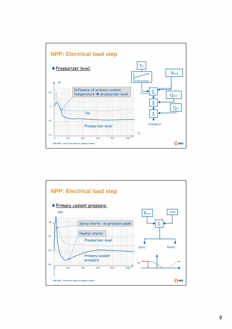
Pressurizer level:
0 200 400 600 800 1000
m
s
0.5
0
-0.5
-1.0
Pressurizer level
Tm
Influence of primary coolant temperature pressurizer level
Tm
Σ
NPZR
reference
measurement
Σ
Σ
actuators
Qdéch
Qch
NPP: Electrical load step
EDF R&D : Créer de la valeur et préparer l’avenir
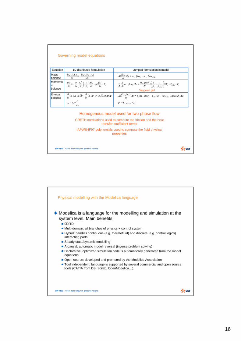
Primary coolant pressure:
PRCP
Σ
155b
Spray Heater
NPP: Electrical load step
0 200 400 600 800 1000
bar
s
159
157
155
153
Primary coolant pressure
Pressurizer level
Spray starts : no pressure peak
Heater starts

9
EDF R&D : Créer de la valeur et préparer l’avenir
Fossil/conventional Power Plant
Principle: load demand = boiler power productionBoiler
Different kinds: drum, once-through…Different fuels: coal, oil, gas…
Impact of coal grinding, oil preheating… on the plant dynamic behavior
Operation constraintsGrid demand
Better steam reserve compared to NPP (drums…): direct coupling between the drum boilers and the generator
Grid operation faultsHow to efficiently operate the plant auxiliaries: coal grinder, pumps… ?How to rapidly evacuate the excess thermal power (steam) ?
EDF R&D : Créer de la valeur et préparer l’avenir
Fossil/conventional Power Plant
Two operating modes for drum boiler:Overriding turbine mode
Overriding boiler mode
1
2
3
4
12
3
4

10
EDF R&D : Créer de la valeur et préparer l’avenir
Fossil/conventional Power Plant
No drum = no steam reserve Need of more efficient feedwater control strategy
Advanced plant control strategyBoiler-turbine coordinated control strategy : all actuators are directly controlled from the load
variation Some optimized anticipations with k∆f variations (ancillary services)
EDF R&D : Créer de la valeur et préparer l’avenir
Why study Plant Performance ?
Performances are heterogeneous depending on the plant typeNuclearFossil fuelCombined cycleHydraulic…
But only one plant performance rule : UCTE (TSO) rules !Regulation compliance for the plant dynamic behaviorPerformance regulation are different for primary and secondary reserves

11
Transfer Function Modelling
EDF R&D : Créer de la valeur et préparer l’avenir
Power plant step response: primary reserve
Moyen de production
Transfert fréquence – puissance
Tranche nucléaire normale
0
01
15
1
f
P
Ss nucléaire+
Tranche nucléaire à GV encrassé
0
01
110
1
f
P
Ss nucléaire+
Tranche charbon à ballon
( )f
f
P
Sss
s
ff
P
Sss
ss
charbon
charbon
∆
++
+
=∆++++
0
02
0
02
2
1
180
1
180
80
1
11606400
1806400
Tranche charbon sans ballon
( )f
f
P
Sss
s
ff
P
Sss
ss
charbon
charbon
∆
++
+
=∆++++
0
02
0
02
2
1
180
1
180
40
1
11606400
1403200
Tranche fioul
( )f
f
P
Sss
s
f
P
Ssss
sss
charbon
fioul
∆
++
+
=++++++
0
02
0
023
23
1
150
1
180
80
1
118010500200000
11608000200000
Centrale hydraulique 0
01
140
19
f
P
Ss
s
ehydrauliqu++−
Frequency Load transfer functionsPower plant
Optimal PWR
Fouling SG PWR
Drum equipped coal plant
No drum equipped coal
plant
Oil plant
Hydraulic plant

12
EDF R&D : Créer de la valeur et préparer l’avenir
Power plant ramp response: primary reserve
EDF R&D : Créer de la valeur et préparer l’avenir
Power plant step response : secondary reserve
The grid remote control signal is not directly applied to the high pressure valve actuators
Moyen de production Transfert fréquence – puissance
Tranche nucléaire normale rP
s 15
1
+
Tranche nucléaire à GV encrassé rP
s 110
1
+
Tranche charbon avec ou sans ballon ( ) rr P
sP
ss 22 180
1
11606400
1
+=
++
Tranche fioul
( ) rr Ps
Pss 22 150
1
11002500
1
+=
++
Centrale hydraulique rP
s
s
140
19
++−
Power plantFrequency Load transfer
functions
Optimal PWR
Fouling SG PWR
Coal plant
Oil plant
Hydraulic plant

13
EDF R&D : Créer de la valeur et préparer l’avenir
Power plant ramp response: secondary reserve
MISTRAL : Simplified Power Plant Modelling

14
EDF R&D : Créer de la valeur et préparer l’avenir
MISTRAL models
Simplified models (transfer functions) of plant dynamic behavior, developed: by R&D/STEP/P1B with Matlab/Simulink for the EDF fleet, for dynamic performance enhancement studies and new control design.
A good trade-off between easy implementation and accurate physical representation
Functional modular architecture: Physical process modules: major physical phenomena (non linear mass, momentum and energy conservation laws) Control loop modules : filters, thresholds, hysteresis…
Validated with measurements data
Scope: steady state and normal transients Ancillary services, all kind of normal operation modes (upper than 20% Pn), major grid operation faults
EDF R&D : Créer de la valeur et préparer l’avenir
MISTRAL models

15
EDF R&D : Créer de la valeur et préparer l’avenir
MISTRAL models
Important variables (reference variable / actuator variable)
Physical Modelling
16
EDF R&D : Créer de la valeur et préparer l’avenir
Governing model equationsGoverning model equations
Energy balance
Momentum balance
Mass balance
Lumped formulation in model1D distributed formulationEquation
x
Av
t
A xxxxx
∂⋅⋅∂−=
∂⋅∂ )()( ρρ
Homogenous model used for two-phase flow
GRETH correlations used to compute the friction and the heat transfer coefficient terms
IAPWS-IF97 polynomials used to compute the fluid physical properties
xxx
x
xx Fx
zg
x
Pv
xt
v −∂∂⋅−
∂∂⋅−
∂∂−=
∂∂
ρ1
2
2
xxxx flowmflowmx
dt
dA ∆+−=∆⋅⋅ __
ρ
xxxxxxx
xx FPP
A
flowmxflowm
dt
d
A
L −−+
−⋅=∆⋅⋅ ∆+
∆+ρρ11_
_2
2
Staggered grid
( ) ( ) xxxxxxxx DAvhx
uAt
ϕπρρ ⋅⋅+⋅⋅⋅∂∂−=⋅⋅
∂∂
x
xxx
Phu
ρ−=
xDflowmhflowmhxdt
udA xxxxxxx
xx ∆⋅⋅⋅+⋅−⋅=∆⋅⋅⋅ ∆+∆+ ϕπρ__
)(
)( , xxwxx TTh −⋅=ϕ
EDF R&D : Créer de la valeur et préparer l’avenir
Physical modelling with the Modelica languagePhysical modelling with the Modelica language
Modelica is a language for the modelling and simulation at the system level. Main benefits:
0D/1D Multi-domain: all branches of physics + control system
Hybrid: handles continuous (e.g. thermofluid) and discrete (e.g. control logics) interacting partsSteady state/dynamic modelling
A-causal: automatic model reversal (inverse problem solving)Declarative: optimized simulation code is automatically generated from the model equations
Open source: developed and promoted by the Modelica AssociationTool independent: language is supported by several commercial and open source tools (CATIA from DS, Scilab, OpenModelica…).

17
EDF R&D : Créer de la valeur et préparer l’avenir
ThermoSysPro libraryThermoSysPro library
Modelica library for static and dynamic power plant modellingDeveloped in the framework of the ITEA 2 EUROSYSLIB projectWill be released as an open source library with two significant test-cases (concentrated solar power plant and combined cycle power plant)
EDF R&D : Créer de la valeur et préparer l’avenir
Dynamic simulation of the islanding of the 1300 MWe NPP (P4) Dynamic simulation of the islanding of the 1300 MWe NPP (P4)
G control rods position R control rods position

18
Modeling of Steam Generators of Nuclear Power Plants to assess TSP blockage Phenomena and Performance
EDF R&D STEPMickaël MidouDaniel Bouskela Julien Ninet Jean-Mélaine Favennec Baligh El-Hefni
in collaboration withVincent Chip (École Polytechnique)Aurélien Gay (École Polytechnique)
EDF R&D : Créer de la valeur et préparer l’avenir
What is a PWR steam generator ?
Important component:Barrier between the primary and secondary loops : 2nd safety barrierCool the fission reactor and produce steam for the turbine-generatorWorks as a complex counter-current and co-current flow heat exchanger
Feedwater
Between 4 and 5
Circulation ratio = total flow / steam flow
99.75 %Steam quality at outlet
1 800 t/h15 900 t/hMass flow
55 bar155 barMean pressure
270°C284°CTemperature at outlet
220°C322°CTemperature at inlet
Secondary loop
Primary loop
Steam to turbine
Primary water inlet Primary water outlet
WaterSteam
Downcomer
Riser(Boiler)
Separators
Tube support plates (8)
U shaped tubes(3600)
Large Range Water Level

19
EDF R&D : Créer de la valeur et préparer l’avenir
What is the TSP blockage phenomena and its consequence ?
Deposits of iron oxide particles:On the U-tubes outer walls
Impacts the heat exchange capacity
On the quatrefoil sections of the U-tubes support platesReduces the flow rate through the sections
Problem:Reduce cooling efficiency
May lead to safety issues
Tube
Tube Support Plate
Clean foil
Fouled foil
Tube Tube Support Plate
Fouling
EDF R&D : Créer de la valeur et préparer l’avenir
What is the TSP blockage phenomena and its consequence ?
Impact on SG behavior during transient: oscillation of water levelIRSN article (ICONE 16 – May 2008)
EDF-SEPTEN safety study simulation
Surry 2 (1994) measurements

20
EDF R&D : Créer de la valeur et préparer l’avenir
New method to assess TSP blockage
Proposed new methodBased on the analysis of the response of the SG to a particular transient: the periodic testing of the control rods that leads to a 60% power derate in 20 minutes (EP RGL 4)Can be performed between two yearly outages (in comparison with local inspections such as eddy current measurements or camera inspections)Produces a global estimator (instead of local estimators)
Measured data
Simulated data
Profile + (P, H, Q) constraints
Curves identification
TSP blockage rate estimation
EDF R&D : Créer de la valeur et préparer l’avenir
Cold legHot leg
SG model: Modelica model
Control system
Network of connected Modelica components
U-shaped tubes:One equivalent distributed pipeHeat transfer (Dittus-Boelter)
Riser:Dissymmetry between hot and cold legEach leg modelled as a distributed pipeFriction coef. to represent the singular pressure losses due to blockage (Chisholm 1983)Heat transfer from U-tubes (Jens&Lottes)Two-phase flow model (Chisholm 1973)
Downcomer:Each leg modelled as one simple adiabatic pipe to represent the effect of gravity
Separators:Pressure losses (simple pipes)Two-phase cavity
Control system:Water level controlFollow-up of primary mass flow temporal profile during EP RGL4 transient

21
EDF R&D : Créer de la valeur et préparer l’avenir
Results and conclusion
It is possible to compute a global estimator of the TSP blockage rate. This indicator is very useful for the planning of the yearly maintenance operations.
This global estimator is obtained using a dynamic model of the SG written in the object-oriented Modelica language.It is important to know how PWR components are for ancillary services : reserves must be available at any time
New Advanced Controller at Cordemais 5 (France)

22
EDF R&D : Créer de la valeur et préparer l’avenir
Q600 coal power plantQ600 coal power plant
Matlab / Simulink Model
EDF R&D : Créer de la valeur et préparer l’avenir
Advanced control methodology
On-site open loop testsPI in manual modeSteps applied to the process (actuators)
Modelling, identification algorithmsDesign
Advanced controller synthesis (H∞ controller)Simulation in closed loop (comparisons between advanced and conventional controller)
Implementation & on-site validation tests

23
EDF R&D : Créer de la valeur et préparer l’avenir
Primary criteria Secondary criteria
Advanced controller for ancillary services
Response simulation
EDF R&D : Créer de la valeur et préparer l’avenir
Advanced controller for ancillary services
Load follow-up under normal operation: ref Peb = P0 + K.∆f + N.Pr
NAC
Classical PID controller
On site validation tests

24
EDF R&D : Créer de la valeur et préparer l’avenir
Advanced controller for ancillary services
The Model Base Anticipation (MBA) added value
Open-loop anticipation on Actuators and References
Enhancement of dynamic performance must be taken into account for system studies.
Primary reserve Secondary reserve
ReferenceNAC
PID controller


