Technical Data
IEC Push Button SpecificationsBulletin Numbers 800F, 800FC, 800FD, 800B, 800MB, and 800MR
Additional ResourcesThese documents contain additional information concerning related products from Rockwell Automation.
You can view or download publications at http://www.rockwellautomation.com/literature/. To order paper copies of technical documentation, contact your local Allen-Bradley distributor or Rockwell Automation sales representative.
Topic Page Topic Page
800F 22.5 mm Push Buttons 800FD 22.5 mm Monolithic Push Buttons
Specifications 3 Momentary Push Button Operators 49
Momentary Push Buttons 6 Pilot Light Devices 50
Pilot Lights 10 Selector Switch Operators 51
Selector Switches 11 Push-Pull/Twist-to-Release Mushroom Operators 51
Key-Operated Selector Switches 16 Specifications 52
Push-Pull Operators 18 Approximate Dimensions 53
Momentary Mushroom Push Buttons 22 800B 16 mm Push Buttons
Momentary Multi-Operators 23 Specifications 54
Reset Operators 26 Operator Assembly Sequence/Target Table and Operator Position 55
Selector Push Button Operators 27 Approximate Dimensions 56
Toggle Switch Operators 28 800MR/800MB IEC Oiltight Operators
Back-of-Panel Components 29 800MR Momentary Contact Push Buttons 57
Assembled Stations with DeviceNet 31 800MR Push-Pull Operators 59
Legend Plates/Caps 32 800MR Selector Switches 61
Approximate Dimensions 33 800MR Pilot Lights & Wobble Sticks 66
Assembled Station Pinout Chart 39 800MB Momentary Contact Push Buttons 67
598 General Purpose Push Button Enclosures 40 800MB Pilot Lights 70
800FC 22.5 mm Configured Pendant Stations 800MB/MR Specifications 71
Operator Mounting/Sequence 41 800MB/MR Approximate Dimensions 72
1-, 2-, and 3-Speed Operators 42
Configured Pendant Stations 43
Specifications 45
Approximate Dimensions 47
Resource Description
Industrial Automation Wiring and Grounding Guidelines, publication 1770-4.1 Provides general guidelines for installing a Rockwell Automation industrial system.
Product Certifications website, http://www.ab.com Provides declarations of conformity, certificates, and other certification details.

IP65/66, Type 4/4X/13 Engineering grade thermoplastics Chemical-resistant for harsh environments
Bul. 800FP PlasticOperators Bul. 800FM Die-Cast Metal
Operators
IP65/66, Type 4/13 Die-cast metal construction Chrome-plated
Plastic Latch with Contact Block
Rugged snap-fit design for plastic or metal latch Stackable contact blocks Rotating collar for easy one-hand latch removal Color-coded contact block plungers for contact identification
Metal Latch with Contact Block
Legend Plate (Optional)
Operator
Mounting Ring (Included with Operator)
Latch
Contact Block(s) and/orPower Modules
800F 22.5 mm Push Buttons IEC Push Button Specifications
Rockwell Automation Publication 800-TD008A-EN-P2
Assembly Overview3-Across x 2-Deep Back-of-Panel (6 Circuits Max.)
Bulletin 800FM Metal OperatorsBulletin 800FP Plastic Operators
IEC Push Button Specifications 800F 22.5 mm Push Buttons
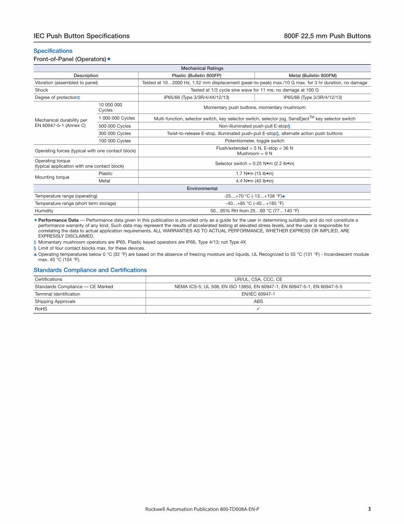
Mechanical Ratings
Description Plastic (Bulletin 800FP) Metal (Bulletin 800FM)
Vibration (assembled to panel) Tested at 10…2000 Hz, 1.52 mm displacement (peak-to-peak) max./10 G max. for 3 hr duration, no damage
Shock Tested at 1/2 cycle sine wave for 11 ms; no damage at 100 G
Degree of protection‡ IP65/66 (Type 3/3R/4/4X/12/13) IP65/66 (Type 3/3R/4/12/13)
Mechanical durability perEN 60947-5-1 (Annex C)
10 000 000Cycles Momentary push buttons, momentary mushroom
1 000 000 Cycles Multi-function, selector switch, key selector switch, selector jog, SensEjectTM key selector switch
500 000 Cycles Non-illuminated push-pull E-stop§
300 000 Cycles Twist-to-release E-stop, illuminated push-pull E-stop§, alternate action push buttons
100 000 Cycles Potentiometer, toggle switch
Operating forces (typical with one contact block) Flush/extended = 5 N, E-stop = 36 NMushroom = 9 N
Operating torque(typical application with one contact block) Selector switch = 0.25 N•m (2.2 lb•in)
Mounting torquePlastic 1.7 N•m (15 lb•in)
Metal 4.4 N•m (40 lb•in)
Environmental
Temperature range (operating) -25…+70 °C (-13…+158 °F)♣Temperature range (short term storage) -40…+85 °C (-40…+185 °F)
Humidity 50…95% RH from 25…60 °C (77…140 °F)
Performance Data — Performance data given in this publication is provided only as a guide for the user in determining suitability and do not constitute aperformance warranty of any kind. Such data may represent the results of accelerated testing at elevated stress levels, and the user is responsible forcorrelating the data to actual application requirements. ALL WARRANTIES AS TO ACTUAL PERFORMANCE, WHETHER EXPRESS OR IMPLIED, AREEXPRESSLY DISCLAIMED.
‡ Momentary mushroom operators are IP65. Plastic keyed operators are IP66, Type 4/13; not Type 4X.§ Limit of four contact blocks max. for these devices.♣ Operating temperatures below 0 °C (32 °F) are based on the absence of freezing moisture and liquids, UL Recognized to 55 °C (131 °F) - Incandescent module
max. 40 °C (104 °F).
Rockwell Automation Publication 800-TD008A-EN-P 3
Standards Compliance and Certifications
Certifications UR/UL, CSA, CCC, CE
Standards Compliance — CE Marked NEMA ICS-5; UL 508, EN ISO 13850, EN 60947-1, EN 60947-5-1, EN 60947-5-5
Terminal Identification EN/IEC 60947-1
Shipping Approvals ABS
RoHS
Front-of-Panel (Operators)Specifications

Electrical Ratings
Standard contact block ratings
Screw Termination Spring Clamp Termination
A600, Q600600V AC
A300, Q300300V AC
AC 15, DC 13 to IEC/EN 60947-5-1 and UL 508, 17V, 5 mA min.
Low voltage contact block ratings‡ 5V, 1 mA DC min.C300, R150, AC 15, DC 13 to EN 60947-5-1 and UL 508
Nominal Voltage Range Current Draw Frequency
LED Module Ratings
24…120V AC/DC24V AC24V DC120V AC240V AC
20…132V AC/DC10…29V AC10…30V DC
102…132V AC204…264V AC
15 mA (AC), 12 mA (DC)31 mA24 mA6 mA6 mA
50/60 Hz, DC50/60 Hz
DC50/60 Hz50/60 Hz
Thermal current 10 A max. enclosed (40 °C ambient) to UL508, EN 60947-5-1
Insulation voltage (Ui) Screw terminal = 690V, spring-clamp = 300V
Wire capacity (screw terminal)§ #18…12 AWG (0.75…2.5 mm2)Max. (2) #14 AWG or (1) #12 AWG
Wire capacity (spring-clamp terminal) #18…14 AWG (0.75…1.5 mm2) One per spring clamp, two spring clamps per terminal
Recommended tightening torque on screw terminals 0.7…0.9 N•m (6…8 lb•in)
Dielectric strength (minimum) 2500V for one minute
External short circuit protectionStandard blocks 10 A type gL/gG cartridge fuse to EN 60269-2-1 or
gN (Class J to UL 248-8 or Class C to UL 248-4)
Low voltage contact blocks 6 A type gL/gG cartridge fuse to EN 60269-2-1 orgN (Class J to UL 248-8 or Class C to UL 248-4)
Electrical shock protection Finger-safe conforming to IP2X
Mechanical Ratings
Vibration (assembled to panel) Tested at 10…2000 Hz, 1.52 mm displacement (peak-to-peak) max./10 G max. 6 hr
Shock Tested at 1/2 cycle sine wave for 11 ms and no damage at 100 G max.
Contact durability per EN 60947-5-1 (Annex C) 10 000 000 cycles
Contact operation
N.O. Slow double make and break
N.C. & S.M.C.B.
Slow double make and break — positive opening
→N.O.E.M. Double break / double make, early make
N.C.L.B.
Double break / double make, late break — positive opening
→
N.C.E.B.
Double break / double make, early break — positive opening
→
Push button travel to change electrical stateN.C. and N.O.E.M. 1.5 mm (0.060 in.)
N.O. and N.C.L.B. 2.5 mm (0.1 in.)
Operating forces (typical)Single circuit contact block 3.4 N
Dual circuit contact block 5…6.5 N
Illumination
LED Dominant WavelengthGreenRedWhite
525 nm629 nm
—
LED Luminous IntensityGreenRedWhite
780 mcd780 mcd360 mcd
Incandescent maximum wattage 2.6 W
Materials
Springs Stainless steel and zinc coated music wire
Electrical contactsStandard Silver-nickel
Low voltage Gold-plated over silver
TerminalsScrew Brass
Spring-clamp Silver-plated brass
Performance Data — see note on page 3.‡ Low voltage contacts are recommended for applications below 17V, 5 mA.
§ Wires less than #18 AWG (0.75 mm2) may not hold in terminal securely.
800F 22.5 mm Push Buttons IEC Push Button Specifications
Rockwell Automation Publication 800-TD008A-EN-P4
Back-of-Panel Components

IEC Push Button Specifications 800F 22.5 mm Push Buttons
Component For Use with Material Used
Panel gasket All operators Nitrile, TPE
Diaphragm seal Illuminated push button, non-illuminated push button Automotive industry acceptablesilicone
K-seal Selector switch, key selector switch, push/twist-to-release E-stop, key E-stop,push/pull mushroom Nitrile
Diaphragm retainer, return spring I Illuminated push button, non-illuminated push button, momentary mushroom Stainless steel
Return spring II Reset, selector switch, key selector switch, alternate action, push/twist-to-releaseE-stop, key E-stop, push/pull mushroom Zinc-coated music wire
Button cap/mushroom head Non-illuminated push button, momentary mushroom, reset, push/twist-to-releaseE-stop, key E-stop, push/pull mushroom, multi-function PBT/polycarbonate blend
2-color molded button cap Non-illuminated push button PBT/polycarbonate blend
Lens Multi-function Acetal
Lens, knob Illuminated push button, illuminated momentary mushroom, illuminated selector switch Polyamide
Knob Non-illuminated selector switch Glass-filled polyamide
Plastic bezel/bushing INon-illuminated push button, illuminated push button, momentary mushroom, selectorswitch, key selector switch, push/twist-to-release E-stop, key E-stop, push/pullmushroom, multi-function, reset
Glass-filled polyamide
Plastic bezel/bushing II, jam nut Pilot light, reset jam nut, reset pushers Glass-filled PBT
Metal bezel/bushing All metal operators Zinc
Diffuser Illuminated push button, pilot light Polycarbonate
Legend frames — Glass-filled polyamide
Plastic mounting ring All plastic operators Glass-filled polyamide
Metal mounting ring All metal operators Chromated zinc
Plastic latch — Glass-filled polyamide
Metal latch — Chromated zinc + stainless steel
Plastic enclosure — PBT/polycarbonate blend
Metal enclosure — Aluminum
Terminal screws LED module, incandescent module, contact blocks Zinc-plated steel with chromate
Terminals LED module, incandescent module, contact blocks Brass with silver-nickel contacts
Spring clamps LED module, incandescent module, contact blocks Stainless steel
Lamp socket Incandescent module Brass
Housing Incandescent module, LED module Glass-filled polyamide
Low-voltage terminals Contact blocks Gold-plated silver-nickelcontacts
Low-voltage spanner Contact blocks Gold-plated silver-nickelcontacts
Spanner Contact blocks Brass with silver-nickel contacts
Boot Toggle Switch, illuminated push button, non-illuminated push button, multi-functionilluminated and non-illuminated
Automotive industry acceptablesilicone
Rockwell Automation Publication 800-TD008A-EN-P 5
Material Listing
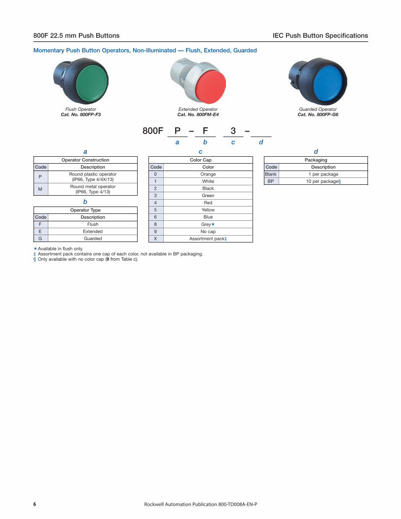
Flush OperatorCat. No. 800FP-F3
Extended OperatorCat. No. 800FM-E4
Guarded OperatorCat. No. 800FP-G6
800F P – F 3 –a b c d
aOperator Construction
Code Description
P Round plastic operator(IP66, Type 4/4X/13)
M Round metal operator(IP66, Type 4/13)
bOperator Type
Code Description
F Flush
E Extended
G Guarded
cColor Cap
Code Color
0 Orange
1 White
2 Black
3 Green
4 Red
5 Yellow
6 Blue
8 Grey
9 No cap
X Assortment pack‡
dPackaging
Code Description
Blank 1 per package
BP 10 per package§
800F 22.5 mm Push Buttons IEC Push Button Specifications
Rockwell Automation Publication 800-TD008A-EN-P6
Available in flush only.‡ Assortment pack contains one cap of each color, not available in BP packaging.§ Only available with no color cap (9 from Table c).
Momentary Push Button Operators, Non-Illuminated — Flush, Extended, Guarded
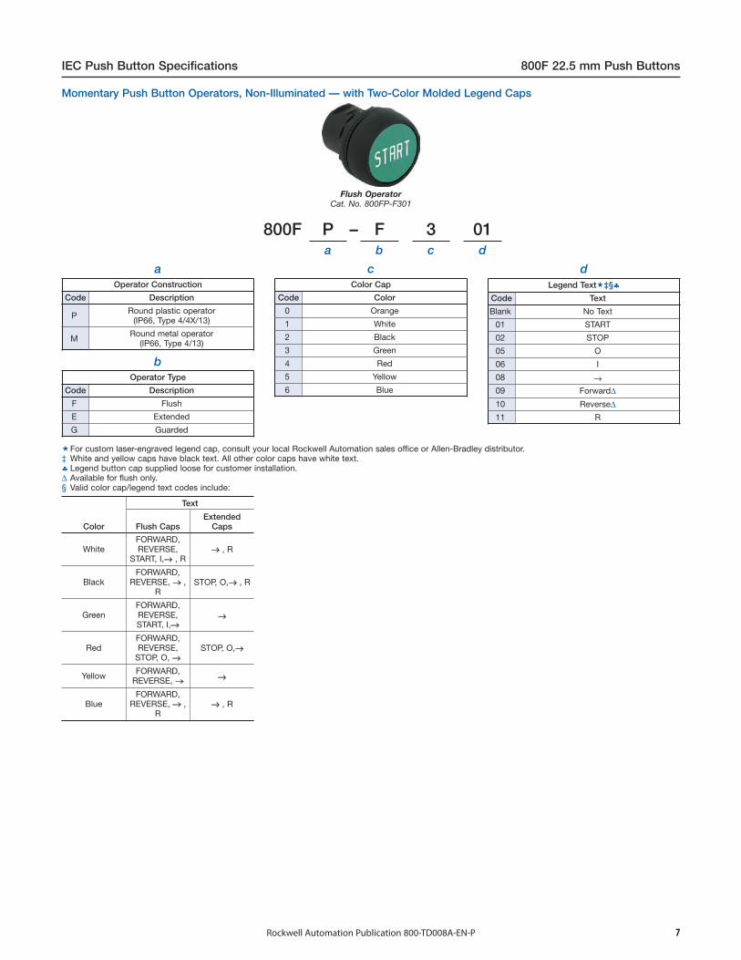
800F P – F 3 01a b c d
aOperator Construction
Code Description
P Round plastic operator(IP66, Type 4/4X/13)
M Round metal operator(IP66, Type 4/13)
bOperator Type
Code Description
F Flush
E Extended
G Guarded
cColor Cap
Code Color
0 Orange
1 White
2 Black
3 Green
4 Red
5 Yellow
6 Blue
dLegend Text‡§♣
Code Text
Blank No Text
01 START
02 STOP
05 O
06 I
08 →09 Forward∆10 Reverse∆11 R
Flush OperatorCat. No. 800FP-F301
Color
Text
Flush CapsExtended
Caps
WhiteFORWARD,REVERSE,
START, I,→ , R→ , R
BlackFORWARD,
REVERSE, → ,R
STOP, O,→ , R
GreenFORWARD,REVERSE,START, I,→
→
RedFORWARD,REVERSE,
STOP, O, →STOP, O,→
Yellow FORWARD,REVERSE, → →
BlueFORWARD,
REVERSE, → ,R
→ , R
IEC Push Button Specifications 800F 22.5 mm Push Buttons
Rockwell Automation Publication 800-TD008A-EN-P 7
Momentary Push Button Operators, Non-Illuminated — with Two-Color Molded Legend Caps
For custom laser-engraved legend cap, consult your local Rockwell Automation sales office or Allen-Bradley distributor.‡ White and yellow caps have black text. All other color caps have white text.♣ Legend button cap supplied loose for customer installation.∆ Available for flush only.§ Valid color cap/legend text codes include:
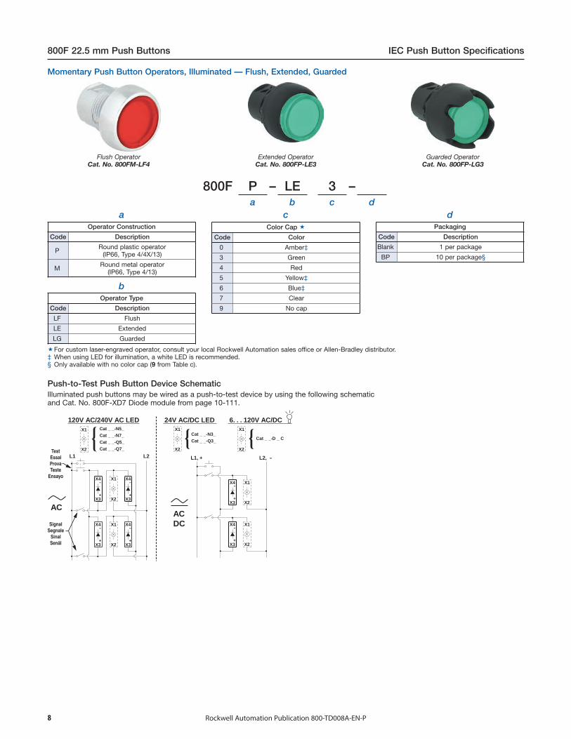
Flush OperatorCat. No. 800FM-LF4
Extended OperatorCat. No. 800FP-LE3
Guarded OperatorCat. No. 800FP-LG3
800F P – LE 3 –a b c d
aOperator Construction
Code Description
P Round plastic operator(IP66, Type 4/4X/13)
M Round metal operator(IP66, Type 4/13)
bOperator Type
Code Description
LF Flush
LE Extended
LG Guarded
cColor Cap
Code Color
0 Amber‡
3 Green
4 Red
5 Yellow‡
6 Blue‡
7 Clear
9 No cap
dPackaging
Code Description
Blank 1 per package
BP 10 per package§
800F 22.5 mm Push Buttons IEC Push Button Specifications
Rockwell Automation Publication 800-TD008A-EN-P8
Illuminated push buttons may be wired as a push-to-test device by using the following schematicand Cat. No. 800F-XD7 Diode module from page 10-111.
Push-to-Test Push Button Device Schematic
For custom laser-engraved operator, consult your local Rockwell Automation sales office or Allen-Bradley distributor.‡ When using LED for illumination, a white LED is recommended.§ Only available with no color cap (9 from Table c).
Momentary Push Button Operators, Illuminated — Flush, Extended, Guarded
X4
L1
AC
L2 L1, + L2, -
X1
X3 X2
-
+
X4
X3
-
+
X4 X1
X3 X2
-
+
X4
X3
-
+
X4
X3
-
+
X1
X2
X1
X2
X1
X2
X4
X3
-
+
Cat _ _-N5_
Cat _ _-N7_
Cat _ _-Q5_
Cat _ _-Q7_
Cat _ _-N3_
Cat _ _-Q3_
X1
X2
X1
X2
AC DC
120V AC/240V AC LED 24V AC/DC LED
Cat _ _-D _ C
6. . . 120V AC/DC
Test Essai Prova Teste
Ensayo
Signal Segnale
Sinal Senãl

800F M – FA 3a b c
aOperator Construction
Code Description
P Round plastic operator(IP66, Type 4/4X/13)
M Round metal operator(IP66, Type 4/13)
bOperator Type
Code Description
FA Non-illuminated, flush, alternate action
cColor Cap‡
Code Color
0 Orange
1 White
2 Black
3 Green
4 Red
5 Yellow
6 Blue
9 No cap
X Assortment pack
800F P – LFA 3a b c
aOperator Construction
Code Description
P Round plastic operator(IP66, Type 4/4X/13)
M Round metal operator(IP66, Type 4/13)
bOperator Type♣∆
Code Description
LFA Illuminated, flush, alternate action
IEC Push Button Specifications 800F 22.5 mm Push Buttons
Rockwell Automation Publication 800-TD008A-EN-P
cColor Cap♦
Code Color
0 Amber♠3 Green
4 Red
5 Yellow♠6 Blue♠7 Clear
9 No lens
9
Cat. No. 800FM-FA3
Cat. No. 800FP-LFA3
♣ Must use N.O.E.M. or N.C. contacts.∆ LED module required for illumination, can not use incandescent module.♦ For custom laser-engraved operator, consult your local Rockwell Automation sales office or
Allen-Bradley distributor..♠ Use of a white LED is recommended.
Alternate Action Operators — Illuminated
Must use N.O.E.M. or N.C. contacts.‡ For custom laser-engraved legend cap, consult your local Rockwell Automation sales office or
Allen-Bradley distributor.
Alternate Action Operators — Non-Illuminated
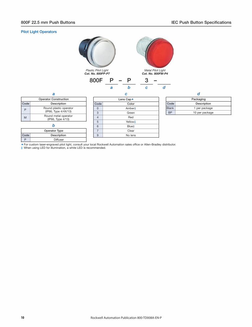
800F P – P 3 –a b c d
aOperator Construction
Code Description
P Round plastic operator(IP66, Type 4/4X/13)
M Round metal operator(IP66, Type 4/13)
bOperator Type
Code Description
P Diffuser
cLens Cap
Code Color
0 Amber‡
3 Green
4 Red
5 Yellow‡
6 Blue‡
7 Clear
9 No lens
dPackaging
Code Description
Blank 1 per package
BP 10 per package
800F 22.5 mm Push Buttons IEC Push Button Specifications
Rockwell Automation Publication 800-TD008A-EN-P10
Plastic Pilot LightCat. No. 800FP-P7
Metal Pilot LightCat. No. 800FM-P4
For custom laser-engraved pilot light, consult your local Rockwell Automation sales office or Allen-Bradley distributor.‡ When using LED for illumination, a white LED is recommended.
Pilot Light Operators

800F P – S M2 2 –a b c d e f
aOperator Construction
Code Description
P Round plastic operator(IP66, Type 4/4X/13)
M Round metal operator(IP66, Type 4/13)
bOperator Type
Code Description
S Standard knob
H Knob lever‡
dKnob/Insert Color
Code Knob Color Insert Color
2 Black White
eOrientation
Code Description
Blank Standard
N 90° offset§
IEC Push Button Specifications 800F 22.5 mm Push Buttons
Rockwell Automation Publication 800-TD008A-EN-P 11
fPackaging
Code Description
Blank 1 per package
BP 10 per package∆
Standard KnobCat. No. 800FP-SM22
Knob LeverCat. No. 800FP-HM22
Target Table and Operator Position
Contact Type♣N.O. O X
N.C. X O
Note: X = Closed/O = OpenTarget table for spring return from left is reversed from what is shown in the table.♣ Contact selection is limited to the following options, consult your local Rockwell Automation sales office
or Allen-Bradley distributor for other options.
cOperator Function
Code Type
M2Maintained (60° switching angle)
L2
Spring return from left(60° switching angle)
R2
Spring return from right(60° switching angle)
Switching Angle
2-Position Selector Switch Operators, Non-Illuminated
‡ 30 mm hole spacing will not work if knob lever is used. See page 38 for recommended operator panel spacing.§ For use in vertical mount Bul. 800F enclosures.∆ Not available with 90° offset orientation.

800F P – LS M2 3a b c d e
aOperator Construction
Code Description‡
P Round plastic operator(IP66, Type 4/4X/13)
M Round metal operator(IP66, Type 4/13)
bOperator Type
Code Description
LS Standard knob
LH Knob lever∆
dKnob/Insert Color
Code Knob Color Insert Color
0 Amber♦ White
3 Green White
4 Red White
5 Yellow♦ Black
6 Blue♦ White
7 Clear Black
eOrientation
Code Description
Blank Standard
N 90° offset§
800F 22.5 mm Push Buttons IEC Push Button Specifications
Rockwell Automation Publication 800-TD008A-EN-P12
Standard KnobCat. No. 800FP-LSM26
Target Table and Operator Position
Contact Type♦N.O. O X
N.C. X O
Note: X = Closed/O = OpenTarget table for spring return from left is reversed from what is shown in the table.♦ Contact selection is limited to the following options, consult your local Rockwell Automation sales office
or Allen-Bradley distributor for other options.
cOperator Function
Code Type
M2Maintained (60° switching angle)
L2
Spring return from left(60° switching angle)
R2
Spring return from right(60° switching angle)
‡ LED module required for illumination, can not use incandescent module.§ For use in vertical mount enclosures.♣ Crevices may exist on product that may be unsuitable for certain applications. Please consult your local
Rockwell Automation sales office or Allen-Bradley distributor.∆ Only available in clear.♦ Use of a white LED is recommended.
Switching Angle
2-Position Selector Switch Operators, Illuminated ♣

800F P – S M3 2a b c d e f
aOperator Construction
Code Description
P Round plastic operator(IP66, Type 4/4X/13)
M Round metal operator(IP66, Type 4/13)
bOperator Type
Code Description
S Standard knob
H Knob lever
dKnob/Insert Color
Code Knob Color Insert Color
2 Black White
eOrientation
Code Description
Blank Standard
N 90° offset‡
IEC Push Button Specifications 800F 22.5 mm Push Buttons
Rockwell Automation Publication 800-TD008A-EN-P 13
fOperation
Code Description
Blank Standard
CL Center left§
CR Center right§
Standard KnobCat. No. 800FP-SM32
Knob LeverCat. No. 800FM-HM32
Target Table and Operator Position (60° Switching Angle)
Contact Type∆Position on
Mounting Latch
N.O.
Left X O O
Right O O X
Center X O X
Center CL§ X O O
Center CR§ O O X
N.C.
Left O X X
Right X X O
Center O X O
Center CL§ O X X
Center CR§ X X O
Note: X = Closed/O = Open∆ Contact selection is limited to the following options, consult your local Rockwell Automation sales office
or Allen-Bradley distributor for other options.
cOperator Function
Code Type
M3Maintained
L3Spring return from left
R3Spring return from right
B3Spring return from left and right
30 mm hole spacing will not work if knob lever is used. See page 38 for recommended operatorpanel spacing.
‡ For use in vertical mount enclosures.§ The center contact block can have the same target output as the left or right contact block, by
specifying center left (CL) or center right (CR) option.
Switching Angle
3-Position Selector Switch Operators, Non-Illuminated
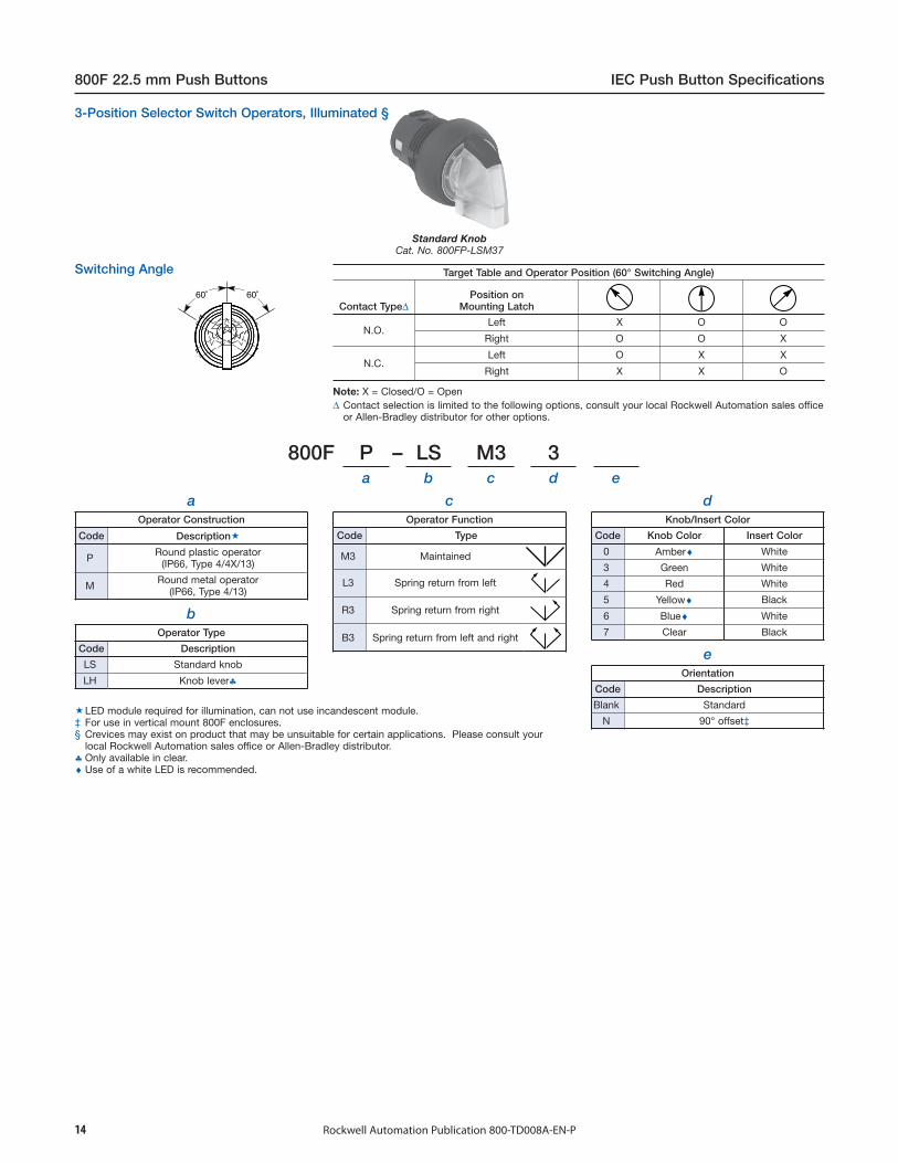
800F P – LS M3 3a b c d e
aOperator Construction
Code Description
P Round plastic operator(IP66, Type 4/4X/13)
M Round metal operator(IP66, Type 4/13)
bOperator Type
Code Description
LS Standard knob
LH Knob lever♣
dKnob/Insert Color
Code Knob Color Insert Color
0 Amber♦ White
3 Green White
4 Red White
5 Yellow♦ Black
6 Blue♦ White
7 Clear Black
eOrientation
Code Description
Blank Standard
N 90° offset‡
800F 22.5 mm Push Buttons IEC Push Button Specifications
Rockwell Automation Publication 800-TD008A-EN-P14
Standard KnobCat. No. 800FP-LSM37
Target Table and Operator Position (60° Switching Angle)
Contact Type∆Position on
Mounting Latch
N.O.Left X O O
Right O O X
N.C.Left O X X
Right X X O
Note: X = Closed/O = Open∆ Contact selection is limited to the following options, consult your local Rockwell Automation sales office
or Allen-Bradley distributor for other options.
cOperator Function
Code Type
M3 Maintained
L3 Spring return from left
R3 Spring return from right
B3 Spring return from left and right
3-Position Selector Switch Operators, Illuminated §
LED module required for illumination, can not use incandescent module.‡ For use in vertical mount 800F enclosures.§ Crevices may exist on product that may be unsuitable for certain applications. Please consult your
local Rockwell Automation sales office or Allen-Bradley distributor.♣ Only available in clear.♦ Use of a white LED is recommended.
Switching Angle
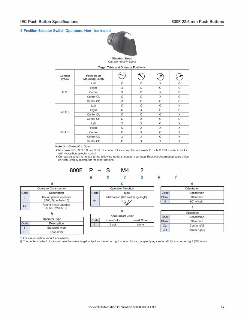
800F P – S M4 2a b c d e f
aOperator Construction
Code Description
P Round plastic operator(IP66, Type 4/4X/13)
M Round metal operator(IP66, Type 4/13)
dKnob/Insert Colorb
Operator Type
Code Description
S Standard knob
H Knob lever
Code Knob Color Insert Color
2 Black White
eOrientation
Code Description
Blank Standard
N 90° offset‡
IEC Push Button Specifications 800F 22.5 mm Push Buttons
fOperation
Code Description
Blank Standard
CL Center left§
CR Center right§
Rockwell Automation Publication 800-TD008A-EN-P 15
Standard KnobCat. No. 800FP-SM42
Target Table and Operator Position
ContactType♣
Position onMounting Latch
N.O.
Left O O X O
Right X O O O
Center X O X O
Center CL O O X O
Center CR X O O O
N.C.E.B.
Left O O O X
Right O X O O
Center CL O O O X
Center CR O X O O
N.C.L.B.
Left X X O X
Right O X X X
Center O X O X
Center CL X X O X
Center CR O X X X
Note: X = Closed/O = OpenMust use N.O., N.C.E.B., or N.C.L.B. contact blocks only. Cannot use N.C. or N.O.E.M. contact blocks
with 4-position selector switch.♣ Contact selection is limited to the following options, consult your local Rockwell Automation sales office
or Allen-Bradley distributor for other options.
cOperator Function
Code Type
M4Maintained (45° switching angle)
4-Position Selector Switch Operators, Non-Illuminated
‡ For use in vertical mount enclosures.§ The center contact block can have the same target output as the left or right contact block, by specifying center left (CL) or center right (CR) option.

800F M – KM2 1a b c d
aOperator Construction
Code Description
P Round plastic operator(IP66, Type 4/13)
M Round metal operator(IP66, Type 4/13)
dRonis Key Lock§♣∆
Code Key No.
Blank 3825 (Standard)
R 455
01R 3801
02R 3802
03R 3803
04R 3804
05R 3805
06R 3806
27R 4001
28R 4002
29R 4003
30R 4004
31R 4005
32R 4006
33R 4007
800F 22.5 mm Push Buttons IEC Push Button Specifications
Rockwell Automation Publication 800-TD008A-EN-P16
Key Selector SwitchCat. No. 800FP-KM21R
Target Table and Operator Position
Contact Type♦N.O. O X
N.C. X O
Note: X = Closed/O = OpenTarget table for spring return from left is reversed from what is shown in the table.♦ Contact selection is limited to the following options, consult your local Rockwell Automation sales office
or Allen-Bradley distributor for other options.
bOperator Type
Code Type
KM2 Maintained(60° switching angle)
KL2 Spring return from left(60° switching angle)
KR2 Spring return from right(60° switching angle)
cKey Removal Position‡
Code Position
1 Left
2 Right
3 Both
Master Key System Key Code
No Master Key
‡ Key removal in maintained positions only.§ Keyed operators are IP66, Type 4/13.♣ Not intended for high security applications. Interoperability is possible with certain key/cylinder lock combinations. Consult your local Rockwell Automation
sales office or Allen-Bradley distributor for interoperability information.∆ For replacement Ronis keys, see Accessories, consult your local Rockwell Automation sales office or Allen-Bradley distributor.
Switching Angle
2-Position Key-Operated Selector Switches, Non-Illuminated
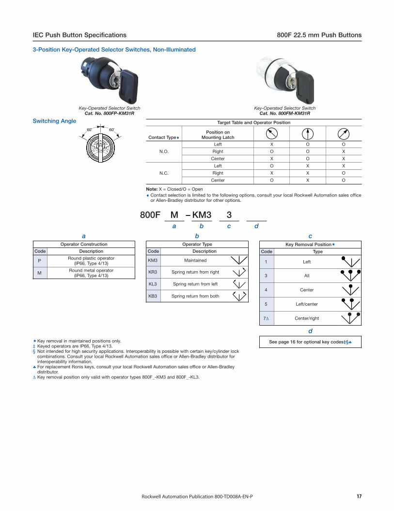
800F M – KM3 3a b c d
aOperator Construction
Code Description
P Round plastic operator(IP66, Type 4/13)
M Round metal operator(IP66, Type 4/13)
IEC Push Button Specifications 800F 22.5 mm Push Buttons
Rockwell Automation Publication 800-TD008A-EN-P 17
d
See page 16 for optional key codes‡§♣
Key-Operated Selector SwitchCat. No. 800FP-KM31R
Key-Operated Selector SwitchCat. No. 800FM-KM31R
Target Table and Operator Position
Contact Type♦Position on
Mounting Latch
N.O.
Left X O O
Right O O X
Center X O X
N.C.
Left O X X
Right X X O
Center O X O
Note: X = Closed/O = Open♦ Contact selection is limited to the following options, consult your local Rockwell Automation sales office
or Allen-Bradley distributor for other options.
bOperator Type
Code Description
KM3 Maintained
KR3 Spring return from right
KL3 Spring return from left
KB3 Spring return from both
cKey Removal Position
Code Type
1 Left
3 All
4 Center
5 Left/center
7∆ Center/right
Key removal in maintained positions only.‡ Keyed operators are IP66, Type 4/13.§ Not intended for high security applications. Interoperability is possible with certain key/cylinder lock
combinations. Consult your local Rockwell Automation sales office or Allen-Bradley distributor forinteroperability information.
♣ For replacement Ronis keys, consult your local Rockwell Automation sales office or Allen-Bradleydistributor.
∆ Key removal position only valid with operator types 800F_-KM3 and 800F_-KL3.
Switching Angle
3-Position Key-Operated Selector Switches, Non-Illuminated
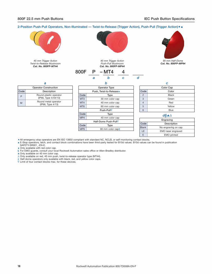
800F P – MT4 4a b c d
aOperator Construction
Code Description
P Round plastic operator(IP66, Type 4/4X/13)
M Round metal operator(IP66, Type 4/13)
bOperator Type
Push, Twist-to-Release♦Code Type
MT3 30 mm color cap
MT4 40 mm color cap
MT6 60 mm color cap
Push-Pull∇Code Type
MP4 40 mm color cap
Half-Dome Push-Pull∇Code Type
MP9 90 mm color cap‡
cColor Cap
Code Color
2 Black
3 Green
4 Red
5 Yellow
6 Blue
d§♣∆Engraving
Code Description
Blank No engraving on cap
LE EMO laser engraved
E EMO printed
800F 22.5 mm Push Buttons IEC Push Button Specifications
Rockwell Automation Publication 800-TD008A-EN-P18
40 mm Trigger ActionTwist-to-Release Mushroom
Cat. No. 800FP-MT44
40 mm Trigger ActionPush-Pull Mushroom
Cat. No. 800FP-MP44
90 mm Half-DomeCat. No. 800FP-MP94
All emergency stop operators are EN ISO 13850 compliant with standard NC, NCLB, or self-monitoring contact blocks.♠ E-Stop operators, latch, and contact block combinations have been third-party tested for B10d values. B10d values can be found in publication
SAFETY-SR001_-EN-E.♦ Only available with red color cap.§ For EMO guards, consult your local Rockwell Automation sales office or Allen-Bradley distributor.♣ Only available on 40 mm color cap.∆ Only available on red, 40 mm push, twist-to-release operator type (MT44).‡ Half-dome operators only available with black, red, and yellow color caps.∇ Limit of four contact blocks max. for these devices.
2-Position Push-Pull Operators, Non-Illuminated — Twist-to-Release (Trigger Action), Push-Pull (Trigger Action)♠

800F P – LMP4 3a b c
aOperator Construction
Code Description
P Round plastic operator(IP66, Type 4/4X/13)
M Round metal operator(IP66, Type 4/13)
bOperator Type
Push, Twist-to-Release§♣Code Type
LMT4 40 mm color cap
LMT6 60 mm color cap
Push-Pull&Code Type
LMP3 30 mm color cap
LMP4 40 mm color cap
LMP6 60 mm color cap
Half-Dome Push-Pull&Code Type
LMP9 90 mm color cap♠
IEC Push Button Specifications 800F 22.5 mm Push Buttons
Rockwell Automation Publication 800-TD008A-EN-P
cLens Cap Color
Code Color
3 Green
4 Red
5 Yellow♦6 Blue∆♦
19
40 mm Illuminated Twist-to-ReleaseCat. No. 800FP-LMT44
40 mm Mushroom Push/PullCat. No. 800FM-LMP44
90 mm Half-DomeCat. No. 800FP-LMP94
LED module required for illumination, can not use incandescent module.‡ All emergency stop operators are EN ISO 13850 compliant with standard NC, NCLB, or self-monitoring contact blocks.∇ E-Stop operators, latch, and contact block combinations have been third-party tested for B10d values. B10d values can be found in publication
SAFETY-SR001_-EN-E.§ Only available with red color cap.♣ 60 mm version has black arrows; 30 and 40 mm versions have white arrows.♦ Use of a white LED is recommended.∆ Only available with 40 mm Push-Pull color cap (LMP4 from Table b).♠ Half-dome operators only available with red and yellow lens cap colors.& Limit of four contact blocks max. for these devices.
2-Position Push-Pull Operators, Illuminated — Twist-to-Release (Trigger Action), Push-Pull (Trigger Action)‡∇

800F P – MK4 4a b c d
aOperator Construction
Code Description
P Round plastic operator(IP66, Type 4/13)
M Round metal operator(IP66, Type 4/13)
bOperator Type
Key Release Mushroom
Code Type
MK4 40 mm
cLens Cap Color
Code Color
4 Red
dRonis Key Lock‡§♣
Code Key No.
Blank 3825 (Standard)
R 455
01R 3801
02R 3802
03R 3803
04R 3804
05R 3805
06R 3806
27R 4001
28R 4002
29R 4003
30R 4004
31R 4005
32R 4006
33R 4007
800F 22.5 mm Push Buttons IEC Push Button Specifications
Rockwell Automation Publication 800-TD008A-EN-P20
40 mm Key Release MushroomCat. No. 800FP-MK44
All emergency stop operators are EN ISO 13850 compliant with standard NC, NCLB, or self-monitoringcontact blocks.
∆ E-Stop operators, latch, and contact block combinations have been third-party tested for B10d values.B10d values can be found in publication SAFETY-SR001_-EN-E.
‡ Keyed operators are IP66, Type 4/13.§ Not intended for high security applications. Interoperability is possible with certain key/cylinder lock
combinations. Consult your local Rockwell Automation sales office or Allen-Bradley distributor forinteroperability information.
♣ For replacement Ronis keys, consult your local Rockwell Automation sales office or Allen-Bradleydistributor.
2-Position Non-Illuminated Operators — Mushroom, Key Release (Trigger Action)∆

800F M – L MM 4 4 E3a b c d e f
aOperator Construction
Code Description
M Round metal operator(IP66, Type 4/13)
bOperator Type
Code Description
Blank Non-illuminated
L Illuminated‡
cOperator Function
Code Description
MMMomentary out,
Maintained center,Momentary in
MPMomentary out,
Maintained center,Maintained in
dCap Size
Code Description
4 40 mm plastic
eCap Color
Code Description
0 Amber§♠2 Black♣3 Green
4 Red
6 Blue§♠7 Clear§♠
IEC Push Button Specifications 800F 22.5 mm Push Buttons
Rockwell Automation Publication 800-TD008A-EN-P
fPositions
Code Description
E3 3-position
21
Illuminated 3-Position Push-PullCat. No. 800FM-LMP44E3
Target Table and Operator Position
Contact Type∇ Out Center In
N.O. O O X
N.C.E.B. X O O
N.C.L.B. X X O
Note: X = Closed/O = OpenMust use N.O., N.C.E.B., or N.C.L.B. contact blocks only. Cannot use N.C. or N.O.E.M. contact blocks
with 3-position push-pull operators.∇ Contact selection is limited to the following options, consult your local Rockwell Automation sales office
or Allen-Bradley distributor for other options.
∆ Sold as stand-alone operator only. Not available as a composite catalog number.‡ LED module required for illumination. Cannot use incandescent module.§ Available in illuminated only.♠ Use of white LED is recommended.♣ Available in non-illuminated only.
3-Position Push-Pull Operators, Illuminated & Non-Illuminated — Mushroom∆
22 Rockwell Automation Publication 800-TD008A-EN-P
800F 22.5 mm Push Buttons IEC Push Button Specifications
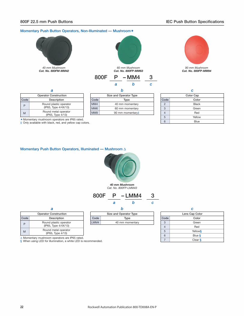
800F P – MM4 3a b c
aOperator Construction
Code Description
P Round plastic operator(IP65, Type 4/4X/13)
M Round metal operator(IP65, Type 4/13)
bSize and Operator Type
Code Type
MM4 40 mm momentary
MM6 60 mm momentary
MM9 90 mm momentary‡
cColor Cap
Code Color
2 Black
3 Green
4 Red
5 Yellow
6 Blue
800F P – LMM4 3a b c
aOperator Construction
Code Description
P Round plastic operator(IP65, Type 4/4X/13)
M Round metal operator(IP65, Type 4/13)
bSize and Operator Type
Code Type
LMM4 40 mm momentary
cLens Cap Color
Code Color
3 Green
4 Red
5 Yellow§
6 Blue §
7 Clear §
40 mm MushroomCat. No. 800FM-MM42
60 mm MushroomCat. No. 800FP-MM63
90 mm MushroomCat. No. 800FP-MM94
40 mm MushroomCat. No. 800FP-LMM43
∆ Momentary mushroom operators are IP65 rated.§ When using LED for illumination, a white LED is recommended.
Momentary Push Button Operators, Illuminated — Mushroom ∆
Momentary mushroom operators are IP65 rated.‡ Only available with black, red, and yellow cap colors.
Momentary Push Button Operators, Non-Illuminated — Mushroom

23Rockwell Automation Publication 800-TD008A-EN-P
IEC Push Button Specifications 800F 22.5 mm Push Buttons
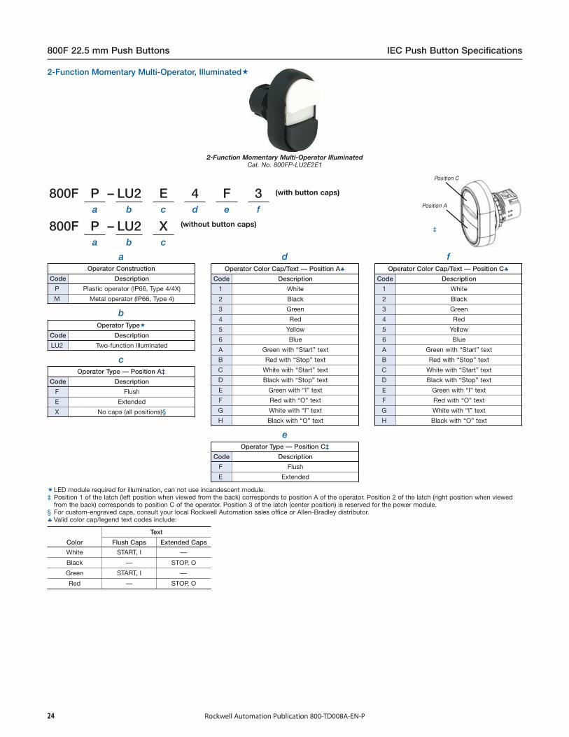
800F P – U2 E 4 F 3a b c d e f
(with button caps)
800F P – U2 Xa b c
(without button caps)
aOperator Construction
Code Description
P Plastic operator (IP66, Type 4/4X)
M Metal operator (IP66, Type 4)
bOperator Type
Code Description
U2 Two-function
cOperator Type — Position A
Code Description
F Flush
E Extended
X No caps (all positions)‡
dOperator Color Cap/Text — Position A§
Code Description
1 White
2 Black
3 Green
4 Red
5 Yellow
6 Blue
A Green with “Start” text
B Red with “Stop” text
C White with “Start” text
D Black with “Stop” text
E Green with “I” text
F Red with “O” text
G White with “I” text
H Black with “O” text
eOperator Type — Position C
Code Description
F Flush
E Extended
fOperator Color Cap/Text — Position C§
Code Description
1 White
2 Black
3 Green
4 Red
5 Yellow
6 Blue
A Green with “Start” text
B Red with “Stop” text
C White with “Start” text
D Black with “Stop” text
E Green with “I” text
F Red with “O” text
G White with “I” text
H Black with “O” text
Color
Text
Flush Caps Extended Caps
White START, I —
Black — STOP, O
Green START, I —
Red — STOP, O
2-Function Momentary Multi-Operator Non-IlluminatedCat. No. 800FP-U2E4F3
2-Function Momentary Multi-Operator, Non-Illuminated
Position 1 of the latch (left position when viewed from the back) corresponds to position A of the operator. Position 2 of the latch (right position when viewedfrom the back) corresponds to position C of the operator.
‡ For custom-engraved caps, consult your local Rockwell Automation sales office or Allen-Bradley distributor.§ Valid color cap/legend text codes include:
800F P – LU2 E 4 F 3a b c d e f
a
800F P – LU2 Xa b c
Operator Construction
Code Description
P Plastic operator (IP66, Type 4/4X)
M Metal operator (IP66, Type 4)
bOperator Type
Code Description
LU2 Two-function Illuminated
cOperator Type — Position A‡
Code Description
F Flush
E Extended
X No caps (all positions)§
dOperator Color Cap/Text — Position A♣
Code Description
1 White
2 Black
3 Green
4 Red
5 Yellow
6 Blue
A Green with “Start” text
B Red with “Stop” text
C White with “Start” text
D Black with “Stop” text
E Green with “I” text
F Red with “O” text
G White with “I” text
H Black with “O” text
eOperator Type — Position C‡
Code Description
F Flush
E Extended
fOperator Color Cap/Text — Position C♣
Code Description
1 White
2 Black
3 Green
4 Red
5 Yellow
6 Blue
A Green with “Start” text
B Red with “Stop” text
C White with “Start” text
D Black with “Stop” text
E Green with “I” text
F Red with “O” text
G White with “I” text
H Black with “O” text
Color
Text
Flush Caps Extended Caps
White START, I —
Black — STOP, O
Green START, I —
Red — STOP, O
800F 22.5 mm Push Buttons IEC Push Button Specifications
Rockwell Automation Publication 800-TD008A-EN-P24
2-Function Momentary Multi-Operator IlluminatedCat. No. 800FP-LU2E2E1
‡
2-Function Momentary Multi-Operator, Illuminated
LED module required for illumination, can not use incandescent module.‡ Position 1 of the latch (left position when viewed from the back) corresponds to position A of the operator. Position 2 of the latch (right position when viewed
from the back) corresponds to position C of the operator. Position 3 of the latch (center position) is reserved for the power module.§ For custom-engraved caps, consult your local Rockwell Automation sales office or Allen-Bradley distributor.♣ Valid color cap/legend text codes include:
(without button caps)
(with button caps)

800F P – U3 E 4 F 3 4a b c d e f g
aOperator Construction
Code
800F P – U3 Xa b c
Description
P Plastic operator (IP66, Type 4/4X)
M Metal operator (IP66, Type 4)
bOperator Type
Code Description
U3 Three-function
cOperator Type — Position A
Code Description
F Flush
E Extended
X No caps (all positions)‡§
dOperator Color Cap/Text — Position A♣
Code Description
1 White
2 Black
3 Green
4 Red
5 Yellow
6 Blue
d (cont'd)Operator Color Cap/Text — Position A♣
Code Description
A Green with “Start” text
B Red with “Stop” text
C White with “Start” text
D Black with “Stop” text
E Green with “I” text
F Red with “O” text
G White with “I” text
H Black with “O” text
eOperator Type — Position C
Code Description
F Flush
E Extended
fOperator Color Cap/Text — Position C♣
Code Description
1 White
2 Black
3 Green
4 Red
5 Yellow
6 Blue
f (cont'd)Operator Color Cap/Text — Position C♣
Code Description
A Green with “Start” text
B Red with “Stop” text
C White with “Start” text
D Black with “Stop” text
E Green with “I” text
F Red with “O” text
G White with “I” text
H Black with “O” text
gOperator Color Cap/Text — Position B§
Code Description
4 Red
B Red with “Stop” text
F Red with “O” text
IEC Push Button Specifications 800F 22.5 mm Push Buttons
Color
Text
Flush Caps Extended Caps
White START, I —
Black — STOP, O
Green START, I —
Red — STOP, O
Rockwell Automation Publication 800-TD008A-EN-P 25
3-Function Momentary Multi-Operator Non-IlluminatedCat. No. 800FP-U3E4F34
3-Function Momentary Multi-Operator, Non-Illuminated
Position 1 of the latch (left position when viewed from the back) corresponds to position A of the operator. Position 2 of the latch (right position when viewedfrom the back) corresponds to position C of the operator. Position 3 of the latch (center position) corresponds to position B of the operator.
‡ For custom-engraved caps, consult your local Rockwell Automation sales office or Allen-Bradley distributor.§ For “no caps” option, (position B) center cap available as red, no text only.♣ Valid color cap/legend text codes include:
(without button caps)
(with button caps)
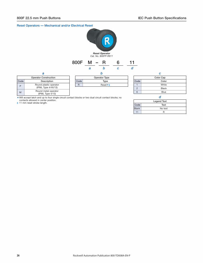
800F M – R 6 11a b c d
aOperator Construction
Code Description
P Round plastic operator(IP66, Type 4/4X/13)
M Round metal operator(IP66, Type 4/13)
bOperator Type
Code Type
R Reset‡
cColor Cap
Code Color
1 White
2 Black
6 Blue
dLegend Text
Code Text
Blank No text
11 R
800F 22.5 mm Push Buttons IEC Push Button Specifications
Rockwell Automation Publication 800-TD008A-EN-P26
Reset OperatorCat. No. 800FP-R611
Reset Operators — Mechanical and/or Electrical Reset
Will accept latch and up to four single circuit contact blocks or two dual circuit contact blocks; nocontacts allowed in center position.
‡ 11 mm reset stroke length.
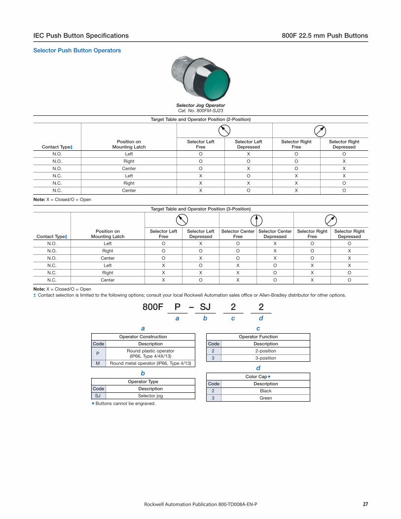
800F P – SJ 2 2a b c d
aOperator Construction
Code Description
P Round plastic operator(IP66, Type 4/4X/13)
M Round metal operator (IP66, Type 4/13)
bOperator Type
Code Description
SJ Selector jog
cOperator Function
Code Description
2 2-position
3 3-position
IEC Push Button Specifications 800F 22.5 mm Push Buttons
Rockwell Automation Publication 800-TD008A-EN-P
dColor Cap
Code Description
2 Black
3 Green
27
Selector Jog OperatorCat. No. 800FM-SJ23
Target Table and Operator Position (2-Position)
Contact Type‡Position on
Mounting LatchSelector Left
FreeSelector LeftDepressed
Selector RightFree
Selector RightDepressed
N.O. Left O X O O
N.O. Right O O O X
N.O. Center O X O X
N.C. Left X O X X
N.C. Right X X X O
N.C. Center X O X O
Note: X = Closed/O = Open
Target Table and Operator Position (3-Position)
Contact Type‡Position on
Mounting LatchSelector Left
FreeSelector LeftDepressed
Selector CenterFree
Selector CenterDepressed
Selector RightFree
Selector RightDepressed
N.O. Left O X O X O O
N.O. Right O O O X O X
N.O. Center O X O X O X
N.C. Left X O X O X X
N.C. Right X X X O X O
N.C. Center X O X O X O
Note: X = Closed/O = Open‡ Contact selection is limited to the following options; consult your local Rockwell Automation sales office or Allen-Bradley distributor for other options.
Selector Push Button Operators
Buttons cannot be engraved.

800F M – J M2a b c
aOperator Construction
Code Description
M Round metal operator (IP66, Type 4/13)
bOperator Type
Code Description
J Toggle switch‡
cOperator Function
Code Description
M2 2-position, maintained
R2 2-position, momentary
M4 4-position, maintained
R4 4-position, momentary
800F 22.5 mm Push Buttons IEC Push Button Specifications
Rockwell Automation Publication 800-TD008A-EN-P28
Toggle Switch OperatorCat. No. 800FM-JM2
Target Table and Operator Position (2-Position)
Contact Type♣Position on
Mounting Latch Toggle Left Center Toggle Right
N.O. Left O O X
N.O. Right X O O
N.O. Center X O X
N.C. Left X X O
N.C. Right O X X
N.C. Center O X O
Note: X = Closed/O = Open
Target Table and Operator Position (4-Position)§
Contact Type♣Position on
Mounting Latch Toggle Up Toggle Left Center Toggle Right Toggle Down
N.O. Left X O O O O
N.O. Right O X O O O
N.O. Center X X O O O
N.C.L.B. Left O X X X X
N.C.L.B. Right X O X X X
N.C.L.B. Center O O X X X
N.C.E.B. Left O O O O X
N.C.E.B. Right O O O X O
Note: X = Closed/O = Open♣ Contact selection is limited to the following options, consult your local Rockwell Automation sales office or Allen-Bradley distributor for other options.§ Must use N.O., N.C.E.B., or N.C.L.B. contact blocks only. Cannot use N.C. or N.O.E.M. contact blocks with 4-position toggle switch.
Use legend plates 800F-34_ and 800F-35_.‡ Silicone boot comes standard with toggle switch, consult your local Rockwell Automation sales office or
Allen-Bradley distributor for replacement boots.
Toggle Switch Operators
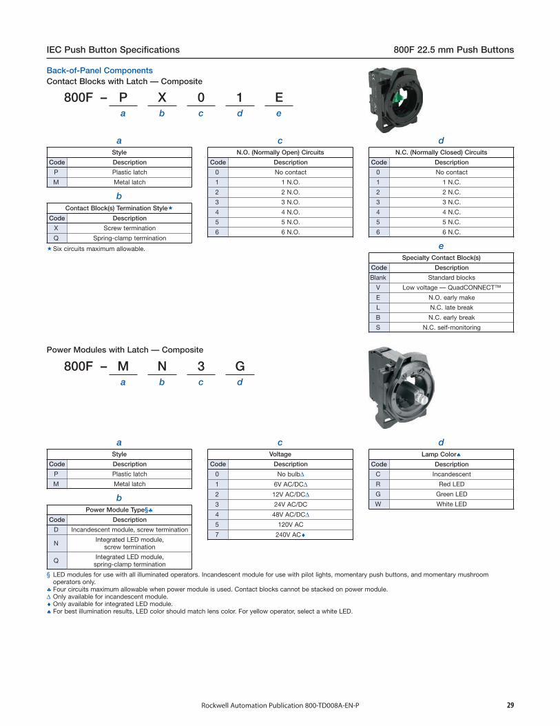
800F – P X 0 1 Ea b c d e
aStyle
Code Description
P Plastic latch
M Metal latch
bContact Block(s) Termination Style
Code Description
X Screw termination
Q Spring-clamp termination
cN.O. (Normally Open) Circuits
Code Description
0 No contact
1 1 N.O.
2 2 N.O.
3 3 N.O.
4 4 N.O.
5 5 N.O.
6 6 N.O.
dN.C. (Normally Closed) Circuits
Code Description
0 No contact
1 1 N.C.
2 2 N.C.
3 3 N.C.
4 4 N.C.
5 5 N.C.
6 6 N.C.
eSpecialty Contact Block(s)
Code Description
Blank Standard blocks
V Low voltage — QuadCONNECT™
E N.O. early make
L N.C. late break
B N.C. early break
S N.C. self-monitoring
800F – M N 3 Ga b c d
aStyle
Code Description
P Plastic latch
M Metal latch
bPower Module Type§♣
Code Description
D Incandescent module, screw termination
N Integrated LED module,screw termination
Q Integrated LED module,spring-clamp termination
cVoltage
Code Description
0 No bulb∆1 6V AC/DC∆2 12V AC/DC∆3 24V AC/DC
4 48V AC/DC∆5 120V AC
7 240V AC♦
IEC Push Button Specifications 800F 22.5 mm Push Buttons
Rockwell Automation Publication 800-TD008A-EN-P 29
dLamp Color♠
Code Description
C Incandescent
R Red LED
G Green LED
W White LED
§ LED modules for use with all illuminated operators. Incandescent module for use with pilot lights, momentary push buttons, and momentary mushroomoperators only.
♣ Four circuits maximum allowable when power module is used. Contact blocks cannot be stacked on power module.∆ Only available for incandescent module.♦ Only available for integrated LED module.♠ For best illumination results, LED color should match lens color. For yellow operator, select a white LED.
Power Modules with Latch — Composite
Six circuits maximum allowable.
Contact Blocks with Latch — CompositeBack-of-Panel Components
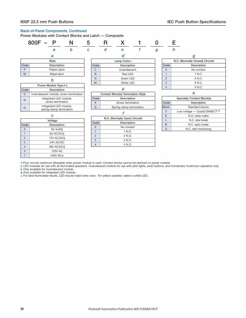
800F – P N 5 R X 1 0 Ea b c d e f g h
aStyle
Code Description
P Plastic latch
M Metal latch
bPower Module Type‡
Code Description
D Incandescent module, screw termination
N Integrated LED module,screw termination
Q Integrated LED module,spring-clamp termination
cVoltage
Code Description
0 No bulb§
1 6V AC/DC§
2 12V AC/DC§
3 24V AC/DC
4 48V AC/DC§
5 120V AC
7 240V AC♣
dLamp Color∆
Code Description
C Incandescent
R Red LED
G Green LED
W White LED
eContact Block(s) Termination Style
Code Description
X Screw termination
Q Spring-clamp termination
fN.O. (Normally Open) Circuits
Code Description
0 No contact
1 1 N.O.
2 2 N.O.
3 3 N.O.
4 4 N.O.
gN.C. (Normally Closed) Circuits
Code Description
0 No contact
1 1 N.C.
2 2 N.C.
3 3 N.C.
4 4 N.C.
hSpecialty Contact Block(s)
Code Description
Blank Standard blocks
V Low voltage — QuadCONNECT™
E N.O. early make
L N.C. late break
B N.C. early break
S N.C. self-monitoring
800F 22.5 mm Push Buttons IEC Push Button Specifications
Rockwell Automation Publication 800-TD008A-EN-P30
Four circuits maximum allowable when power module is used. Contact blocks cannot be stacked on power module.‡ LED modules for use with all illuminated operators. Incandescent module for use with pilot lights, push buttons, and momentary mushroom operators only.§ Only available for incandescent module.♣ Only available for integrated LED module.∆ For best illuminated results, LED should match lens color. For yellow operator, select a white LED.
Power Modules with Contact Blocks and Latch — CompositeBack-of-Panel Components, Continued

800F –a b c d c d e
(Hole 1 c+d) (Hole 2 c+d)
800F –a b c d c d c d e
(Hole 1 c+d) (Hole 2 c+d) (Hole 3 c+d)
800F –a b c d c d c d c d e
(Hole 1 c+d) (Hole 2 c+d) (Hole 3 c+d) (Hole 4 c+d)
aMounting Orientation
Code Description
V Vertical
H Horizontal
bEnclosure Style/Legends
Code Description
A 2-hole/legend frames
B 3-hole/legend frames
C 4-hole/legend frames
D 2-hole/no legend frames
E 3-hole/no legend frames
F 4-hole/no legend frames
H 2-hole/E-stop only no legend frames‡
cOperator Types
Code Description
A Non-illuminated flush button
B Non-illuminated extended button
C Non-illuminated guarded button
D Illuminated flush button ∇E Illuminated extended button ∇F Illuminated guarded button ∇G Non-illuminated 2-pos. selector switch
H Non-illuminated 3-pos. selector switch
J Pilot light (diffused)
K Hole plug &L Non-illuminated TTR E-stop §&M Non-illuminated push pull §&N 2-pos. key selector switch
P 3-pos. key selector switch
R Non-illuminated 40 mm mushroom
T E-stop key release §&U Potentiometer ♣&W Illuminated push pull
X Illuminated 2-pos. maintained selectorswitch
Y Illuminated 3-pos. maintained selectorswitch
Z Illuminated 40 mm mushroom
dColor/Text
Code Description
1 White
2 Black
3 Green
4 Red
5 Yellow
6 Blue
7 Clear
8 Grey ∆9 No cap
0 Amber
A Green with "Start" text
B Red with "Stop" text
C Black with "→" symbol
D Black with "←" symbol
E Black with "↑" symbol
F Black with "↓" symbol
G Green with "I" symbol
H Red with "O" symbol
L Blue with "R" text
M Red with yellow metal guard #N Yellow with yellow metal guard #
IEC Push Button Specifications 800F 22.5 mm Push Buttons
Rockwell Automation Publication 800-TD008A-EN-P 31
eExternal I/O Version♦
Code Description
Blank No external I/O
A 1 input/1 output (sinking)
B 1 input/1 output (sourcing)
C 2 input
E 2 output (sourcing)
F 1 E-stop block ♠G 2 E-stop block ♠H 2 input/2 output
K 2 input/2 output (sourcing)
L 1 input/1 output (sinking) + 1 E-stopblock ♠
M 1 input/1 output (sourcing) + 1 E-stopblock ♠
N 1 input/1 output (sinking) + 2 E-stopblock ♠
P 1 input/1 output (sourcing) + 2 E-stopblock ♠
Q 2 input + 1 E-stop block ♠R 2 input + 2 E-stop block ♠U 2 output (sourcing) + 1 E-stop block ♠W 2 output (sourcing) + 2 E-stop block ♠X 2 input + 1 input/1 output (sinking)
Hole 4
Hole 3
Hole 2
Hole 1
Hole 1
Hole 2
4-Hole Assembled StationCat. No. 800F-VHA3A4J3J4J
Selector Switches in a vertical mount enclosure are mounted with a horizontal orientation.‡ Enclosure Style/Legend option H from Table b can only select one operator from Table c. Valid options
are L, M, and T. Also see footnote §§ Operator Types L, M, and T from Table c may be used as emergency stops. To be valid as an E-Stop,
operators must use color/text option 4 from Table d and it must be placed in the last hole position inthe enclosure, where a yellow round E-stop legend plate is provided. An E-Stop connector also mustbe chosen from Table e. Also see footnote ♠
♣ Potentiometer allowed in first hole position only.∆ Available in flush only.♦ This is an 8-in/4-out device. 2-in and 1-out are assigned to each hole position in the enclosure. If a 2-
hole enclosure is selected, 4-in and 2-out are assigned internally and up to 4 unassigned I/O points canbe assigned to external connectors. This device contains up to two physical external I/O connectors.The "+" symbol in the Description field of table e indicates that two external connectors exist. If an E-Stop connector is used, 2 unassigned I/O points can be assigned to the other connector.
♠ External I/O Versions F, L, M, Q, and U receive only one contact block for the external E-Stop string.These connectors are rated 3 A. If more than 3 A of current is needed or if there are two E-Stopstrings, use External I/O Versions G, N, P, R, and W. These versions receive two contact blocks. Thisallows for 6 A of switching or for two E-Stop strings.
∇ Cannot be ordered with "No Cap" (9 from Table d - Color/Text).& Operator Types K, L, M, T, and U from Table c are not available with legend frames.# Only available with non-illuminated push-pull operator (M from Table c).
2-Hole
4-Hole
3-Hole
Assembled Stations with DeviceNet

32 Rockwell Automation Publication 800-TD008A-EN-P
800F 22.5 mm Push Buttons IEC Push Button Specifications
800F – AF 3 01a b c
aButton Cap Type
Code Description
AF Flush
AE Extended
bColor Cap
Code Description
1 White
2 Black
3 Green
4 Red
5 Yellow
6 Blue
cLegend Text‡§
English
Code Description
01 START
02 STOP
05 O
06 I
08 →09 FORWARD
10 REVERSE
11 RColor
Text
Flush Caps Extended Caps
White FORWARD, REVERSE, START, I, →, R →, R
Black FORWARD, REVERSE, →, R STOP, O, →, R
Green FORWARD, REVERSE, START, I, → →Red FORWARD, REVERSE, STOP, O, → STOP, O, →
Yellow FORWARD, REVERSE, → →Blue FORWARD, REVERSE, →, R →, R
800F – 15YSa b
aSize/Color (Yellow)
Code Description
15Y 60 mm round(30.5 mm mounting hole)
15YS 60 mm round(22.5 mm mounting hole)♦
16Y 90 mm round(22.5 mm mounting hole)♦
bText
Code Description
Blank No text
E112 EMERGENCY STOP
F112 ARRÊT D’URGENCE♠S112 PARO DE EMERGENCIA
G112 NOT HALT
T112 ARRESTO EMERGENZA
N112 NÖDSTOPP, EMERGENCY STOP♠P112 PARADA DE EMERGENCIA
b (cont'd)Text
Code Description
W112 NØDSTOPP, EMERGENCY STOP♠A112 NØDSTOP
B112EMERGENCY STOP, ARRÊTD’URGENCE, PARADA DE
EMERGENCIA♠D112 NOODSTOP♠
M112
NOT HALT, ARRESTO EMERGENZA,ARRÊT D’URGENCE∇
EMERGENCY STOP, ARRÊTD’URGENCE, NOT HALT&
L112 NEYÐARSTOPP, NEYÐARSTOPP♠H112 NÖD-STOP, HÄTÄ-SEIS, NÖD-STOP♠
800F – A F 1 Ca b
aType
Code Description
E Push button extended cap
F Push button flush cap
FA Alternate action cap
FAU Multi-function flush cap (for position A)
EAU Multi-function extended cap (for position A)
FCU Multi-function flush cap (for position C)
ECU Multi-function extended cap (for position C)
Cat. No. 800F-15YSE112
22.5 mmmounting hole
Two-Color Molded Legend Caps — Non-Illuminated Push Buttons
Push Button, Multi-Function Caps
♣ Sold only multiples of 10. Order (quantity of) 10 to receive one package of 10 pieces.♦ Not for use with base mounted contact blocks.♠ Not available on 15YS version.∇ Text printed on the 15Y version only.& Text printed on the 15YS & 16Y versions only.
Emergency Stop Legend Plates ♣
Available in flush only.‡ White and yellow caps have black text. All other
color caps have white text.§ Valid color cap text codes include:
bColor
Code Description
0 Amber
1 White
2 Black
3 Green
4 Red
5 Yellow
6 Blue
33Rockwell Automation Publication 800-TD008A-EN-P
IEC Push Button Specifications 800F 22.5 mm Push Buttons
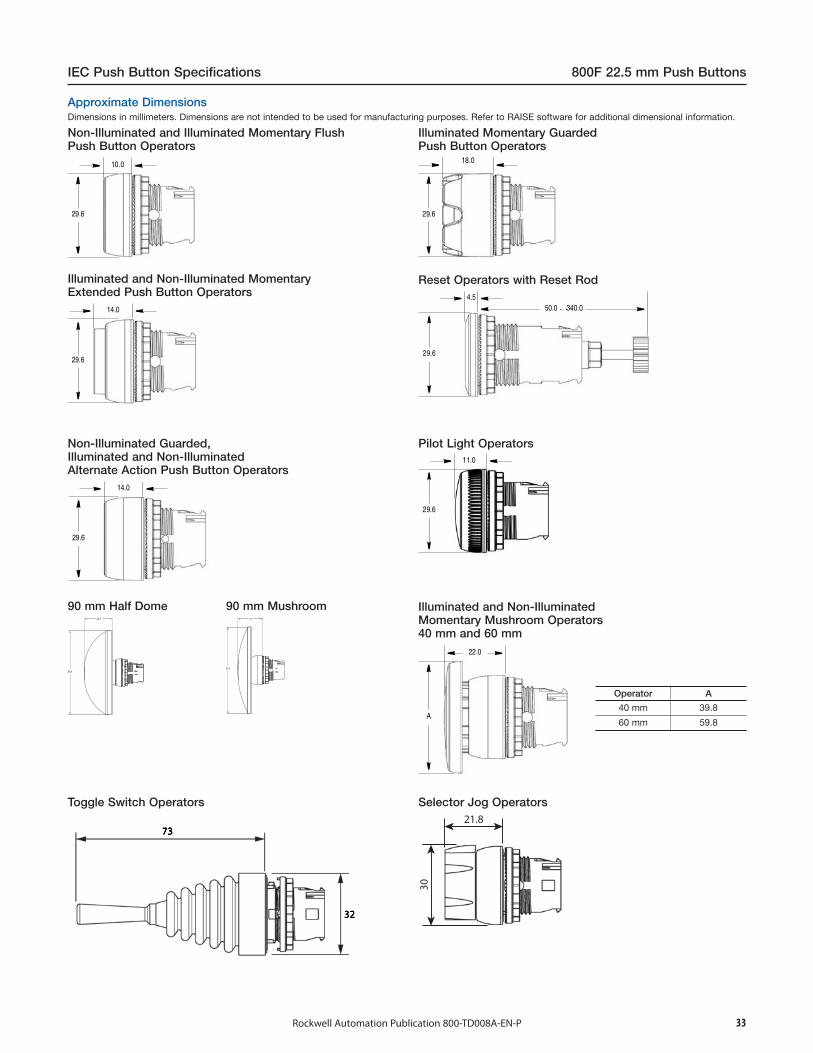
90 mm Half Dome30.1
89.9
90 mm Mushroom26
89.8
...
Operator A
40 mm 39.8
60 mm 59.8
21.8
30
Illuminated and Non-IlluminatedMomentary Mushroom Operators40 mm and 60 mm
Pilot Light Operators
Reset Operators with Reset Rod
Illuminated Momentary GuardedPush Button Operators
Non-Illuminated Guarded,Illuminated and Non-IlluminatedAlternate Action Push Button Operators
Illuminated and Non-Illuminated MomentaryExtended Push Button Operators
Non-Illuminated and Illuminated Momentary FlushPush Button Operators
Dimensions in millimeters. Dimensions are not intended to be used for manufacturing purposes. Refer to RAISE software for additional dimensional information.
Approximate Dimensions
Toggle Switch Operators Selector Jog Operators
22.5
29.6
800F 22.5 mm Push Buttons IEC Push Button Specifications
Rockwell Automation Publication 800-TD008A-EN-P34
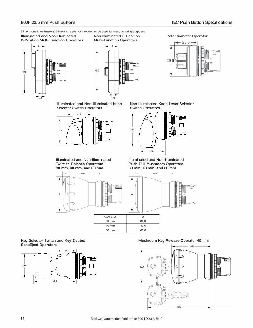
Key Selector Switch and Key EjectedSensEject Operators
Potentiometer Operator
Mushroom Key Release Operator 40 mm
Operator A
30 mm 30.0
40 mm 40.0
60 mm 60.0
Illuminated and Non-IlluminatedTwist-to-Release Operators30 mm, 40 mm, and 60 mm
Illuminated and Non-IlluminatedPush-Pull Mushroom Operators30 mm, 40 mm, and 60 mm
Illuminated and Non-Illuminated2-Position Multi-Function Operators
Non-Illuminated Knob Lever SelectorSwitch Operators
Illuminated and Non-Illuminated KnobSelector Switch Operators
Non-Illuminated 3-PositionMulti-Function Operators
Dimensions in millimeters. Dimensions are not intended to be used for manufacturing purposes.
46 23.1
40
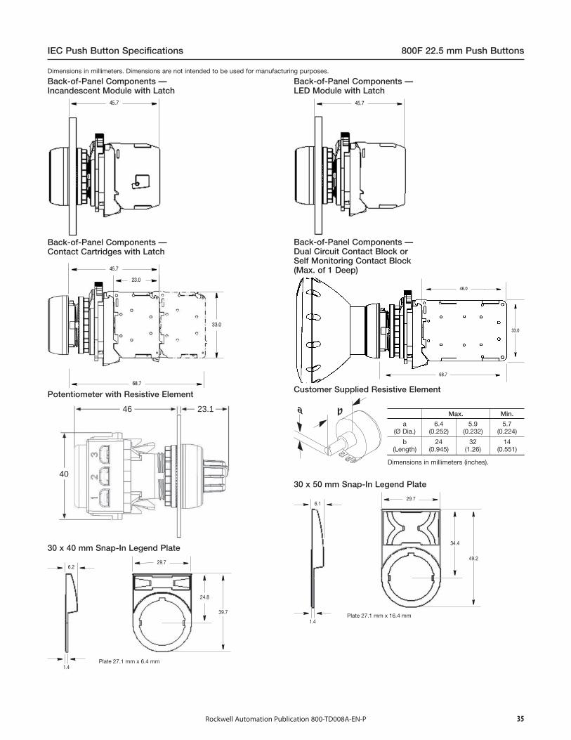
Plate 27.1 mm x 6.4 mm
baMax. Min.
a(Ø Dia.)
6.4(0.252)
5.9(0.232)
5.7(0.224)
b(Length)
24(0.945)
32(1.26)
14(0.551)
Dimensions in millimeters (inches).
Plate 27.1 mm x 16.4 mm
IEC Push Button Specifications 800F 22.5 mm Push Buttons
Rockwell Automation Publication 800-TD008A-EN-P 35
30 x 50 mm Snap-In Legend Plate
Customer Supplied Resistive Element
30 x 40 mm Snap-In Legend Plate
Potentiometer with Resistive Element
Back-of-Panel Components —Dual Circuit Contact Block orSelf Monitoring Contact Block(Max. of 1 Deep)
Back-of-Panel Components —Contact Cartridges with Latch
Back-of-Panel Components —LED Module with Latch
Back-of-Panel Components —Incandescent Module with Latch
Dimensions in millimeters. Dimensions are not intended to be used for manufacturing purposes.

Plate 27.1 mm x 16.4 mm40
66
36
1.3
29.8
3.12
29.6
800F 22.5 mm Push Buttons IEC Push Button Specifications
Rockwell Automation Publication 800-TD008A-EN-P36
Potentiometer Legend Plate(Series A)
Note: Panel thickness range is 1.0…6.0 mm maximum.Panel thickness reduced to 4 mm (standard anti-rotation washer) or 5 mm (thin anti-rotation washer) when optional legend plates areused.
Base Mount Adapter
30 mm to 22.5 mm Hole Adapter
Hole Plug
30 x 50 mm One-Piece Legend Plate
30 x 66 mm One-Piece Legend Plate
30 x 40 mm One-Piece Legend Plate
Anti-Rotation Washer
Trim Washer
Special Multi-FunctionSnap-In Legend Plate
90 mm Round Legend
60 mm Round Legend — 15YS60 mm Round Legend — 15Y 30 x 60 mmSnap-In Legend Plate
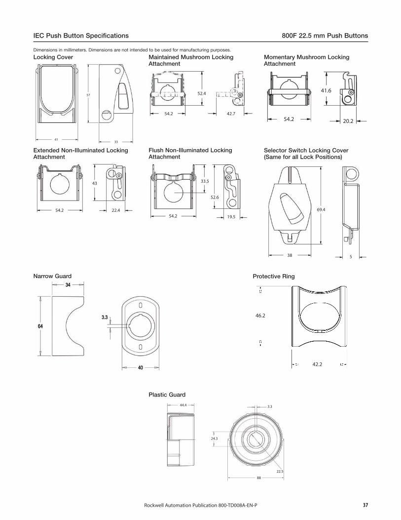
Dimensions in millimeters. Dimensions are not intended to be used for manufacturing purposes.
4133
57
54.2
52.4
42.754.2 20.2
41.6
54.2 22.4
43
54.2
33.5
52.6
19.5
38
69.4
5
46.2
42.2
44.4 3.3
24.3
88
22.5
IEC Push Button Specifications 800F 22.5 mm Push Buttons
Rockwell Automation Publication 800-TD008A-EN-P 37
Plastic Guard
Protective RingNarrow Guard
Selector Switch Locking Cover(Same for all Lock Positions)
Flush Non-Illuminated LockingAttachment
Extended Non-Illuminated LockingAttachment
Momentary Mushroom LockingAttachment
Maintained Mushroom LockingAttachment
Locking CoverDimensions in millimeters. Dimensions are not intended to be used for manufacturing purposes.
L
W
D
D
D
D
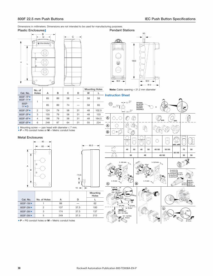
Cat. No.No. ofHoles A B C D
Mounting Holes
W L
800F-1P800F-1Y
185 89 58 — 58 59
800F-1YD 85 89 74 — 58 65
800F-2P 2 124 79 58 31 48 102.5
800F-3P 3 155 79 58 31 48 133
800F-4P 4 186 79 58 31 48 164.5
800F-6P 6 248 87 64 31 55 224
‡ Mounting screw — pan head with diameter ≤ 7 mm.P = PG conduit holes or M = Metric conduit holes
30
A
B
A B
40 50
48 40 / 6060 / 90
ø60, ø90
40 / 60 50 / 6040 50
24,1+0,4–0
22,3+0,4–0
3,2+0,2–0
mmOPTIONAL EN OPTION OPTIONAL OPCIONAL OPZIONALE
=
70 50
30 50
PLASTICPLASTIK
PLASTIQUEPLÁSTICOPLÁSTICA
METALMETALLMÉTALMETALLO
M3,5
A
2
2
23
2
1
1
1
1
3
+
,
EM
ERGENCY
S T O P
4
6
3
1
1,2 Nm10 lb-in
0,7 - 0,9 Nm6 - 8 lb-in
1,7 Nm15 lb-in
4,4 Nm40 lb-in
1- 4,8 mm
1- 6 mm
1- 2,8 mm
1- 4 mm
"Clic"
7 mm
0,75 - 1,5 mm2
(#18 - #14 AWG)
8 mm
0,6 mm 3,5 mm
0,75 - 2,5 mm2
(#18 - #12 AWG)
Ø40 Ø60
2
3
4
5"Clic"
"Clic" "Clic"5
800F 22.5 mm Push Buttons IEC Push Button Specifications
Cat. No. No. of Holes A D
MountingHoles
L
800F-1M 1 99 — 62
800F-2M 2 137 37.5 100
800F-3M 3 174 37.5 137
800F-5M 5 249 37.5 212
P = PG conduit holes or M = Metric conduit holes
Rockwell Automation Publication 800-TD008A-EN-P38
Instruction Sheet
Note: Cable opening = 21.2 mm diameter
Pendant Stations
Metal Enclosures
Plastic Enclosures‡Dimensions in millimeters. Dimensions are not intended to be used for manufacturing purposes.
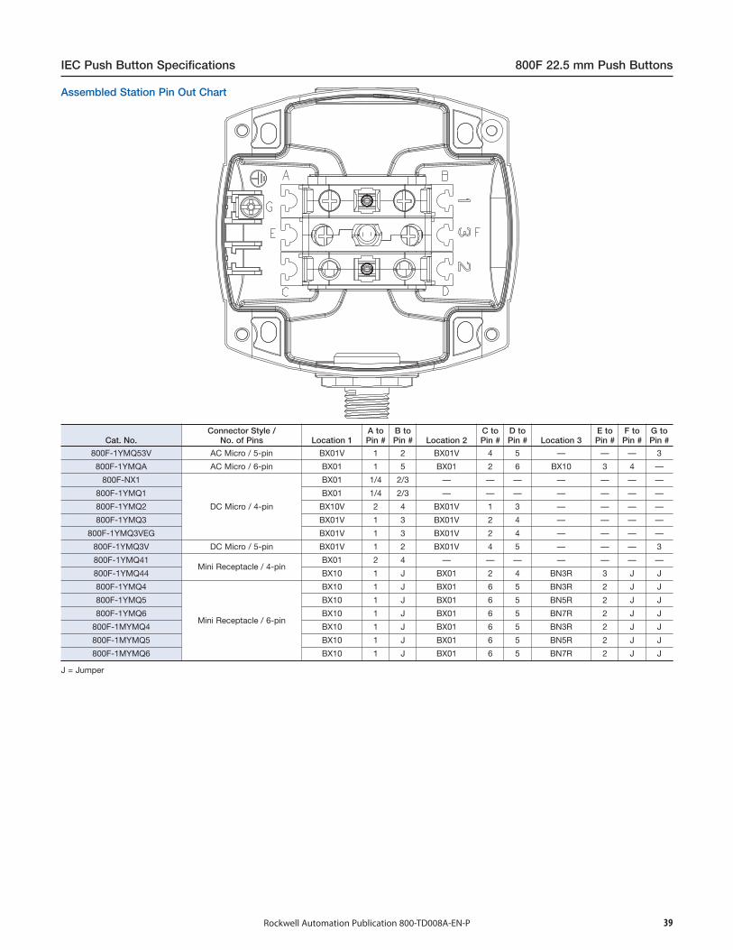
Cat. No.Connector Style /
No. of Pins Location 1A toPin #
B toPin # Location 2
C toPin #
D toPin # Location 3
E toPin #
F toPin #
G toPin #
800F-1YMQ53V AC Micro / 5-pin BX01V 1 2 BX01V 4 5 — — — 3
800F-1YMQA AC Micro / 6-pin BX01 1 5 BX01 2 6 BX10 3 4 —
800F-NX1
DC Micro / 4-pin
BX01 1/4 2/3 — — — — — — —
800F-1YMQ1 BX01 1/4 2/3 — — — — — — —
800F-1YMQ2 BX10V 2 4 BX01V 1 3 — — — —
800F-1YMQ3 BX01V 1 3 BX01V 2 4 — — — —
800F-1YMQ3VEG BX01V 1 3 BX01V 2 4 — — — —
800F-1YMQ3V DC Micro / 5-pin BX01V 1 2 BX01V 4 5 — — — 3
800F-1YMQ41Mini Receptacle / 4-pin
BX01 2 4 — — — — — — —
800F-1YMQ44 BX10 1 J BX01 2 4 BN3R 3 J J
800F-1YMQ4
Mini Receptacle / 6-pin
BX10 1 J BX01 6 5 BN3R 2 J J
800F-1YMQ5 BX10 1 J BX01 6 5 BN5R 2 J J
800F-1YMQ6 BX10 1 J BX01 6 5 BN7R 2 J J
800F-1MYMQ4 BX10 1 J BX01 6 5 BN3R 2 J J
800F-1MYMQ5 BX10 1 J BX01 6 5 BN5R 2 J J
800F-1MYMQ6 BX10 1 J BX01 6 5 BN7R 2 J J
J = Jumper
IEC Push Button Specifications 800F 22.5 mm Push Buttons
Rockwell Automation Publication 800-TD008A-EN-P 39
Assembled Station Pin Out Chart
40 Rockwell Automation Publication 800-TD008A-EN-P
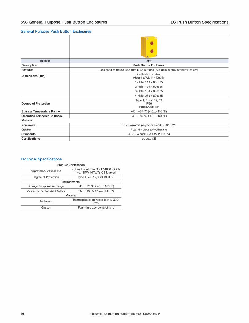
598 General Purpose Push Button Enclosures IEC Push Button Specifications
Bulletin 598
Description Push Button Enclosure
Features Designed to house 22.5 mm push buttons (available in grey or yellow colors)
Dimensions [mm] Available in 4 sizes(Height x Width x Depth)
1-Hole: 110 x 80 x 85
2-Hole: 130 x 80 x 85
3-Hole: 180 x 80 x 85
4-Hole: 250 x 80 x 85
Degree of ProtectionType 1, 4, 4X, 12, 13
IP66Indoor/Outdoor
Storage Temperature Range -40…+75 °C (-40…+158 °F)
Operating Temperature Range -40…+55 °C (-40…+131 °F)
Material
Enclosure Thermoplastic polyester blend, UL94-5VA
Gasket Foam-in-place polyutherane
Standards UL 508A and CSA C22.2, No. 14
Certifications cULus, CE
Technical Specifications
Product Certification
Approvals/Certifications cULus Listed (File No. E54866; GuideNo. NITW, NITW7), CE Marked
Degree of Protection Type 4, 4X, 12, and 13, IP66
Environmental
Storage Temperature Range -40…+75 °C (-40…+158 °F)
Operating Temperature Range -40…+55 °C (-40…+131 °F)
Material
Enclosure Thermoplastic polyester blend, UL945VA
Gasket Foam-in-place polyurethane
General Purpose Push Button Enclosures
41Rockwell Automation Publication 800-TD008A-EN-P
IEC Push Button Specifications 800FC 22.5 mm Configured Pendant Stations
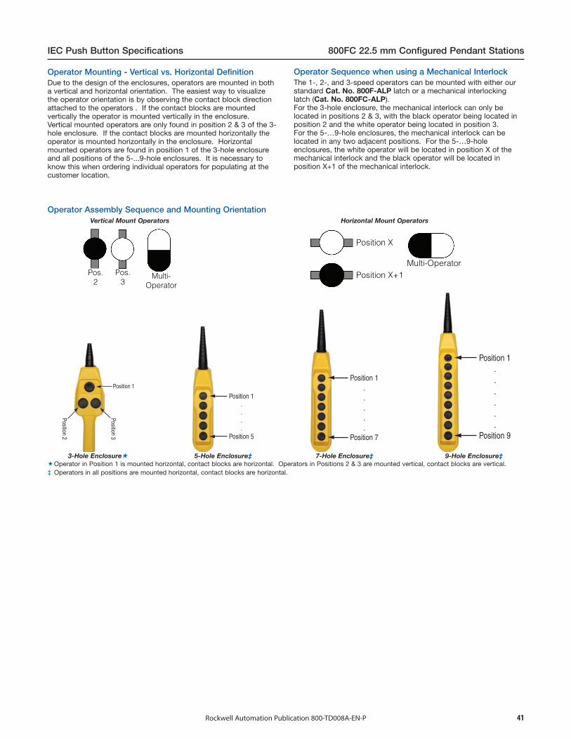
Vertical Mount Operators Horizontal Mount Operators
Pos.2
Pos.3
Multi-Operator
Position X
Position X+1Multi-Operator
Position 1
Position 3
Position 2
Position 1....
Position 5
Position 1.....
Position 7
Position 1......
Position 9
3-Hole Enclosure 5-Hole Enclosure‡ 7-Hole Enclosure‡ 9-Hole Enclosure‡Operator in Position 1 is mounted horizontal, contact blocks are horizontal. Operators in Positions 2 & 3 are mounted vertical, contact blocks are vertical.‡ Operators in all positions are mounted horizontal, contact blocks are horizontal.
Operator Assembly Sequence and Mounting Orientation
The 1-, 2-, and 3-speed operators can be mounted with either ourstandard Cat. No. 800F-ALP latch or a mechanical interlockinglatch (Cat. No. 800FC-ALP).For the 3-hole enclosure, the mechanical interlock can only belocated in positions 2 & 3, with the black operator being located inposition 2 and the white operator being located in position 3.For the 5-…9-hole enclosures, the mechanical interlock can belocated in any two adjacent positions. For the 5-…9-holeenclosures, the white operator will be located in position X of themechanical interlock and the black operator will be located inposition X+1 of the mechanical interlock.
Operator Sequence when using a Mechanical InterlockDue to the design of the enclosures, operators are mounted in botha vertical and horizontal orientation. The easiest way to visualizethe operator orientation is by observing the contact block directionattached to the operators . If the contact blocks are mountedvertically the operator is mounted vertically in the enclosure.Vertical mounted operators are only found in position 2 & 3 of the 3-hole enclosure. If the contact blocks are mounted horizontally theoperator is mounted horizontally in the enclosure. Horizontalmounted operators are found in position 1 of the 3-hole enclosureand all positions of the 5-...9-hole enclosures. It is necessary toknow this when ordering individual operators for populating at thecustomer location.
Operator Mounting - Vertical vs. Horizontal Definition
42 Rockwell Automation Publication 800-TD008A-EN-P
800FC 22.5 mm Configured Pendant Stations IEC Push Button Specifications
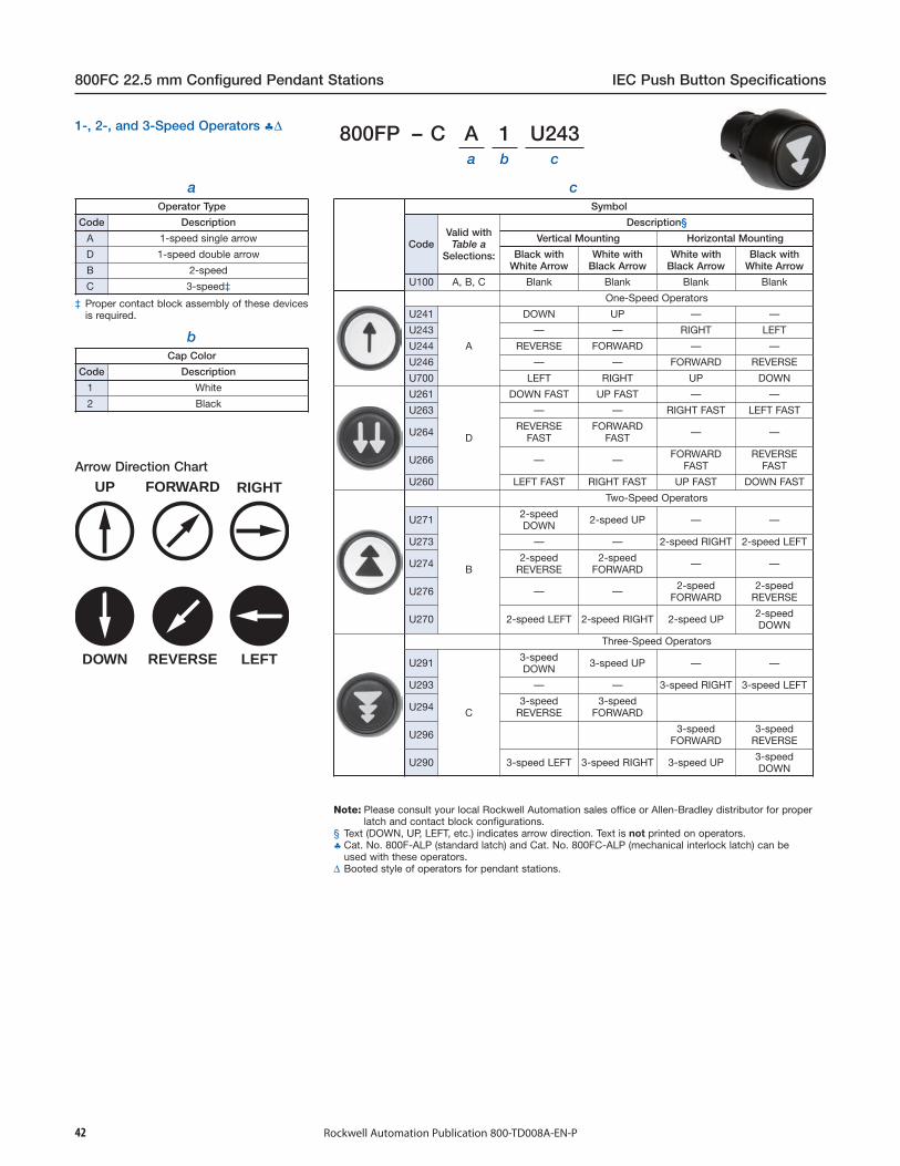
800FP – C A 1 U243a b c
aOperator Type
Code Description
A 1-speed single arrow
D 1-speed double arrow
B 2-speed
C 3-speed‡
UP FORWARD RIGHT
DOWN REVERSE LEFT
bCap Color
Code Description
1 White
2 Black
Note: Please consult your local Rockwell Automation sales office or Allen-Bradley distributor for properlatch and contact block configurations.
§ Text (DOWN, UP, LEFT, etc.) indicates arrow direction. Text is not printed on operators.♣ Cat. No. 800F-ALP (standard latch) and Cat. No. 800FC-ALP (mechanical interlock latch) can be
used with these operators.∆ Booted style of operators for pendant stations.
Arrow Direction Chart
1-, 2-, and 3-Speed Operators ♣∆
cSymbol
CodeValid withTable a
Selections:
Description§
Vertical Mounting Horizontal Mounting
Black withWhite Arrow
White withBlack Arrow
White withBlack Arrow
Black withWhite Arrow
U100 A, B, C Blank Blank Blank Blank
One-Speed Operators
U241
A
DOWN UP — —
U243 — — RIGHT LEFT
U244 REVERSE FORWARD — —
U246 — — FORWARD REVERSE
U700 LEFT RIGHT UP DOWN
U261
D
DOWN FAST UP FAST — —
U263 — — RIGHT FAST LEFT FAST
U264 REVERSEFAST
FORWARDFAST — —
U266 — — FORWARDFAST
REVERSEFAST
U260 LEFT FAST RIGHT FAST UP FAST DOWN FAST
Two-Speed Operators
U271
B
2-speedDOWN 2-speed UP — —
U273 — — 2-speed RIGHT 2-speed LEFT
U274 2-speedREVERSE
2-speedFORWARD — —
U276 — — 2-speedFORWARD
2-speedREVERSE
U270 2-speed LEFT 2-speed RIGHT 2-speed UP 2-speedDOWN
Three-Speed Operators
U291
C
3-speedDOWN 3-speed UP — —
U293 — — 3-speed RIGHT 3-speed LEFT
U294 3-speedREVERSE
3-speedFORWARD
U296 3-speedFORWARD
3-speedREVERSE
U290 3-speed LEFT 3-speed RIGHT 3-speed UP 3-speedDOWN
‡ Proper contact block assembly of these devicesis required.

43Rockwell Automation Publication 800-TD008A-EN-P
IEC Push Button Specifications 800FC 22.5 mm Configured Pendant Stations
800FC –a b b1 c c1 d d1 e e1 f f1 g g1 h h1 j j1 k k1
Pos. 1 Pos. 2 Pos. 3 Pos. 4 Pos. 5 Pos. 6 Pos. 7 Pos. 8 Pos. 93-…9-hole 5-…9-hole
aEnclosure Code
Voltage 12 LegendPlate
3-Hole 5-Hole 7-Hole 9-Hole
Code Code Code Code
24V AC/DCNo
2 4 6 8
120V AC 3 5 7 9
24V AC/DCYes
A C E G
120V AC B D F H
12 Enclosure code is always required. Voltage is used to select LEDs for illuminated operators. Standard contact blocks are used for both 24V and 120V enclosures.
Only available in position 1 of a 3-hole enclosure and in positions 1 & 2 of a5-…9-hole enclosure.
‡ Monolithic style device provided.§ For a 3-hole enclosure, when a mechanical interlock (c1 & d1 = M or B) is
selected with a 1-…3-speed operator, the black operator will be located inposition 2 of the enclosure and the opposite white operator will be placed inposition 3 of the enclosure (Example: ABMAFM or BDMBUM).For a 5-...9-hole enclosure, when a mechanical interlock (b1…k1 = M or B)is selected with a 1-…3-speed operator, the white operator will be locatedin position X of the mechanical interlock and the opposite black operatorwill be placed in position X+1 of the mechanical interlock (Example:AFMABM or BUMBDM).
♣ Interlock and/or rubber boot selection = N (no interlock, no additionalboots) is not allowed.
∆ Interlock and/or rubber boot selection = E (electrical interlock, no additionalboots) is not allowed.
♦ Interlock and/or rubber boot selection = M (mechanical interlock) is notallowed.
♠ Interlock and/or rubber boot selection = B (electrical and mechanicalinterlock) is not allowed.
∇ Interlock and/or rubber boot selection = R (no interlock, additional rubberboot) is not allowed.
& Interlock and/or rubber boot selection = S (electrical interlock, additionalrubber boot) is not allowed.
# Only available in position 1 for a 3-hole enclosure, positions 1 and/or 5 for a5-hole enclosure, positions 1 and/or 7 for a 7-hole enclosure, and positions1 and/or 9 for a 9-hole enclosure.
11 For proper installation, a trim washer or Cat. No. 800F-36_ legend platemust be installed with this operator.
b1…k1
Interlock and/or Rubber Boot
Code Description
N No interlock, no additional bootsE Electrical interlock, no additional bootsM Mechanical interlock, boots standard §B Electrical and mechanical interlock, boots standard §R No interlock, additional rubber bootS Electrical interlock, additional rubber boot
b…kOperator Type
Single Speed Operators for use with Mechanical Interlock§∇&11
Code Description Legend Plate Text(When Selected)
A2 Black operator (no text or symbol) Blank
AB Black operator with arrow(reverse — down/left) O/H CRANE, REVERSE
AD Black operator with arrow (down) LIFT, DOWNAL Black operator with arrow (left) HOIST, LEFTA1 White operator (no text or symbol) Blank
AF White operator with arrow(forward — up/right) O/H CRANE, FORWARD
AR White operator with arrow (right) HOIST, RIGHTAU White operator with arrow (up) LIFT, UP
Fast Single Speed Operators for use with Mechanical Interlock§∇&11
Code Description Legend Plate Text(When Selected)
DB Black operator with double arrow(reverse fast — down/left) O/H CRANE, REVERSE, FAST
DD Black operator with double arrow(down fast) LIFT, DOWN FAST
DL Black operator with double arrow(left fast) O/H CRANE, LEFT FAST
DF White operator with double arrow(forward fast — up/right) O/H CRANE, FORWARD, FAST
DR White operator with double arrow(right fast) O/H CRANE, RIGHT FAST
DU White operator with double arrow(up fast) LIFT, UP FAST
Two-Speed Operators for use with Mechanical Interlock§∇&11
Code Description Legend Plate Text(When Selected)
B2 Black operator (no text or symbol) Blank
BB Black operator with arrow(reverse — down/left)
1-2 SPEED, O/H CRANE,REVERSE
BD Black operator with arrow (down) 1-2 SPEED, LIFT, DOWNBL Black operator with arrow (left) 1-2 SPEED, HOIST, LEFTB1 White operator (no text or symbol) Blank
BF White operator with arrow(forward — up/right)
1-2 SPEED, O/H CRANE,FORWARD
BR White operator with arrow (right) 1-2 SPEED, HOIST, RIGHTBU White operator with arrow (up) 1-2 SPEED, LIFT, UP
Three-Speed Operators for use with Mechanical Interlock§♣∆∇&11
Code Description Legend Plate Text(When Selected)
C2 Black operator (no text or symbol) Blank
CB Black operator with arrow(reverse — down/left)
1-2-3 SPEED, O/H CRANE,REVERSE
CD Black operator with arrow (down) 1-2-3 SPEED, LIFT, DOWNCL Black operator with arrow (left) 1-2-3 SPEED, HOIST, LEFTC1 White operator (no text or symbol) Blank
CF White operator with arrow(forward — up/right)
1-2-3 SPEED, O/H CRANE,FORWARD
CR White operator with arrow (right) 1-2-3 SPEED, HOIST, RIGHTCU White operator with arrow (up) 1-2-3 SPEED, LIFT, UP
Note: A code from Tables b…k and b1…k1 must be specified for each operator to create a valid cat. no.
Configured Pendant StationsCatalog Number Explanation
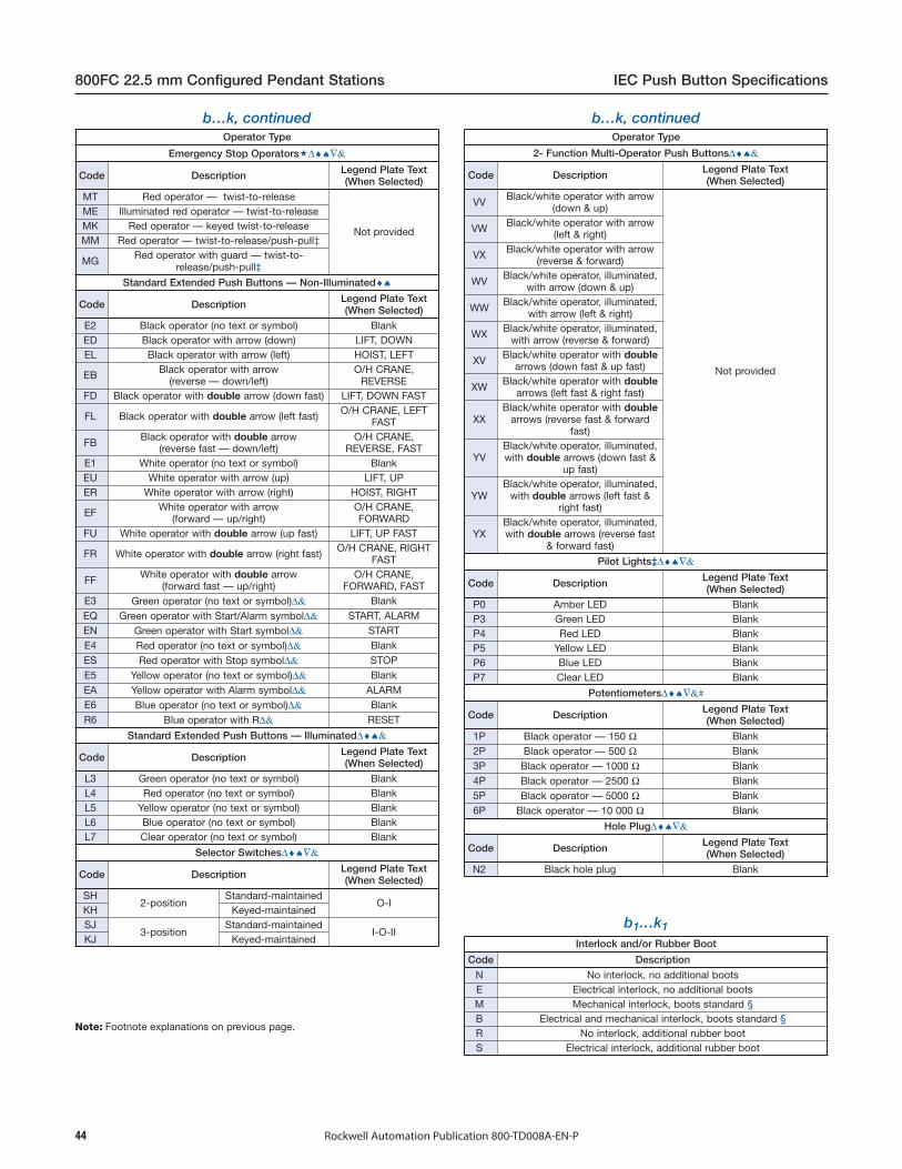
44 Rockwell Automation Publication 800-TD008A-EN-P
800FC 22.5 mm Configured Pendant Stations IEC Push Button Specifications
b…k, continuedOperator Type
Emergency Stop Operators∆♦♠∇&
Code Description Legend Plate Text(When Selected)
MT Red operator — twist-to-release
Not provided
ME Illuminated red operator — twist-to-releaseMK Red operator — keyed twist-to-releaseMM Red operator — twist-to-release/push-pull‡
MG Red operator with guard — twist-to-release/push-pull‡
Standard Extended Push Buttons — Non-Illuminated♦♠
Code Description Legend Plate Text(When Selected)
E2 Black operator (no text or symbol) BlankED Black operator with arrow (down) LIFT, DOWNEL Black operator with arrow (left) HOIST, LEFT
EB Black operator with arrow(reverse — down/left)
O/H CRANE,REVERSE
FD Black operator with double arrow (down fast) LIFT, DOWN FAST
FL Black operator with double arrow (left fast) O/H CRANE, LEFTFAST
FB Black operator with double arrow(reverse fast — down/left)
O/H CRANE,REVERSE, FAST
E1 White operator (no text or symbol) BlankEU White operator with arrow (up) LIFT, UPER White operator with arrow (right) HOIST, RIGHT
EF White operator with arrow(forward — up/right)
O/H CRANE,FORWARD
FU White operator with double arrow (up fast) LIFT, UP FAST
FR White operator with double arrow (right fast) O/H CRANE, RIGHTFAST
FF White operator with double arrow(forward fast — up/right)
O/H CRANE,FORWARD, FAST
E3 Green operator (no text or symbol)∆& BlankEQ Green operator with Start/Alarm symbol∆& START, ALARMEN Green operator with Start symbol∆& STARTE4 Red operator (no text or symbol)∆& BlankES Red operator with Stop symbol∆& STOPE5 Yellow operator (no text or symbol)∆& BlankEA Yellow operator with Alarm symbol∆& ALARME6 Blue operator (no text or symbol)∆& BlankR6 Blue operator with R∆& RESET
Standard Extended Push Buttons — Illuminated∆♦♠&
Code Description Legend Plate Text(When Selected)
L3 Green operator (no text or symbol) BlankL4 Red operator (no text or symbol) BlankL5 Yellow operator (no text or symbol) BlankL6 Blue operator (no text or symbol) BlankL7 Clear operator (no text or symbol) Blank
Selector Switches∆♦♠∇&
Code Description Legend Plate Text(When Selected)
SH2-position
Standard-maintainedO-I
KH Keyed-maintainedSJ
3-positionStandard-maintained
I-O-IIKJ Keyed-maintained
Note: Footnote explanations on previous page.
b…k, continuedOperator Type
2- Function Multi-Operator Push Buttons∆♦♠&
Code Description Legend Plate Text(When Selected)
VV Black/white operator with arrow(down & up)
Not provided
VW Black/white operator with arrow(left & right)
VX Black/white operator with arrow(reverse & forward)
WV Black/white operator, illuminated,with arrow (down & up)
WW Black/white operator, illuminated,with arrow (left & right)
WX Black/white operator, illuminated,with arrow (reverse & forward)
XV Black/white operator with doublearrows (down fast & up fast)
XW Black/white operator with doublearrows (left fast & right fast)
XXBlack/white operator with double
arrows (reverse fast & forwardfast)
YVBlack/white operator, illuminated,with double arrows (down fast &
up fast)
YWBlack/white operator, illuminated,
with double arrows (left fast &right fast)
YXBlack/white operator, illuminated,with double arrows (reverse fast
& forward fast)
Pilot Lights‡∆♦♠∇&
Code Description Legend Plate Text(When Selected)
P0 Amber LED BlankP3 Green LED BlankP4 Red LED BlankP5 Yellow LED BlankP6 Blue LED BlankP7 Clear LED Blank
Potentiometers∆♦♠∇&#
Code Description Legend Plate Text(When Selected)
1P Black operator — 150 Ω Blank2P Black operator — 500 Ω Blank3P Black operator — 1000 Ω Blank4P Black operator — 2500 Ω Blank5P Black operator — 5000 Ω Blank6P Black operator — 10 000 Ω Blank
Hole Plug∆♦♠∇&
Code Description Legend Plate Text(When Selected)
N2 Black hole plug Blank
b1…k1
Interlock and/or Rubber Boot
Code Description
N No interlock, no additional bootsE Electrical interlock, no additional bootsM Mechanical interlock, boots standard §B Electrical and mechanical interlock, boots standard §R No interlock, additional rubber bootS Electrical interlock, additional rubber boot
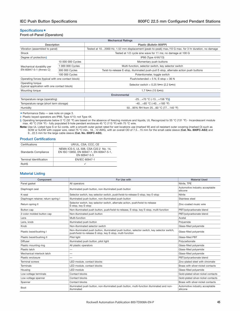
45Rockwell Automation Publication 800-TD008A-EN-P
IEC Push Button Specifications 800FC 22.5 mm Configured Pendant Stations
Mechanical Ratings
Description Plastic (Bulletin 800FP)
Vibration (assembled to panel) Tested at 10…2000 Hz, 1.52 mm displacement (peak-to-peak) max./10 G max. for 3 hr duration, no damage
Shock Tested at 1/2 cycle sine wave for 11 ms; no damage at 100 G
Degree of protection‡ IP66 (Type 4/4X/13)
Mechanical durability perEN 60947-5-1 (Annex C)
10 000 000 Cycles Momentary push buttons
1 000 000 Cycles Multi-function, selector switch, key selector switch
300 000 Cycles Twist-to-release E-stop, illuminated push-pull E-stop, alternate action push buttons
100 000 Cycles Potentiometer, toggle switch
Operating forces (typical with one contact block) Flush/extended = 5 N, E-stop = 36 N
Operating torque(typical application with one contact block) Selector switch = 0.25 N•m (2.2 lb•in)
Mounting torque 1.7 N•m (15 lb•in)
Environmental
Temperature range (operating) -25…+70 °C (-13…+158 °F)§
Temperature range (short term storage) -40…+85 °C (-40…+185 °F)
Humidity 50…95% RH from 25…60 °C (77…140 °F)
Performance Data — see note on page 3.‡ Plastic keyed operators are IP66, Type 4/13; not Type 4X.§ Operating temperatures below 0 °C (32 °F) are based on the absence of freezing moisture and liquids, UL Recognized to 55 °C (131 °F) - Incandescent module
max. 40 °C (104 °F) - fully populated 9-hole pendant enclosure 45 °C (113 °F) with 75 °C wire.Note: Use UL Listed type S or SJ cords, with a smooth outer jacket rated for wet locations use (marked W) and oil resistant outer covering (marked O) such as
SOW or SJOW with copper wire, rated 75 °C min., 18…12 AWG, with an overall OD of 7.5…15 mm for the small cable sleeve (Cat. No. 800FC-AS3) and9…22.5 mm for the large cable sleeve (Cat. No. 800FC-AS5).
Component For Use with Material Used
Panel gasket All operators Nitrile, TPE
Diaphragm seal Illuminated push button, non-illuminated push button Automotive industry acceptablesilicone
K-seal Selector switch, key selector switch, push/twist-to-release E-stop, key E-stop Nitrile
Diaphragm retainer, return spring I Illuminated push button, non-illuminated push button Stainless steel
Return spring II Selector switch, key selector switch, alternate action, push/twist-to-releaseE-stop, key E-stop Zinc-coated music wire
Button cap Non-illuminated push button, push/twist-to-release, E-stop, key E-stop, multi-function PBT/polycarbonate blend
2-color molded button cap Non-illuminated push button PBT/polycarbonate blend
Lens Multi-function Acetal
Lens, knob Illuminated push button Polyamide
Knob Non-illuminated selector switch Glass-filled polyamide
Plastic bezel/bushing I Non-illuminated push button, illuminated push button, selector switch, key selector switch,push/twist-to-release E-stop, key E-stop, multi-function Glass-filled polyamide
Plastic bezel/bushing II Pilot light Glass-filled PBT
Diffuser Illuminated push button, pilot light Polycarbonate
Plastic mounting ring All plastic operators Glass-filled polyamide
Plastic latch — Glass-filled polyamide
Mechanical interlock latch — Glass-filled polyamide
Plastic enclosure — PBT/polycarbonate blend
Terminal screws LED module, contact blocks Zinc-plated steel with chromate
Terminals LED module, contact blocks Brass with silver-nickel contacts
Housing LED module Glass-filled polyamide
Low-voltage terminals Contact blocks Gold-plated silver-nickel contacts
Low-voltage spanner Contact blocks Gold-plated silver-nickel contacts
Spanner Contact blocks Brass with silver-nickel contacts
Boot Illuminated push button, non-illuminated push button, multi-function illuminated and non-illuminated
Automotive industry acceptablesilicone
Certifications UR/UL, CSA, CCC, CE
Standards ComplianceNEMA ICS-5, UL 508, CSA C22.2 No. 14,EN ISO 13850, EN 60947-1, EN 60947-5-1,
EN 60947-5-5
Terminal Identification EN/IEC 60947-1
RoHS
Product Certifications
Material Listing
Front-of-Panel (Operators)Specifications

46 Rockwell Automation Publication 800-TD008A-EN-P
800FC 22.5 mm Configured Pendant Stations IEC Push Button Specifications
Back-of-Panel ComponentsElectrical Ratings
Standard contact block ratingsA600, Q600
600V ACAC 15, DC 13 to IEC/EN 60947-5-1 and UL 508, 17V, 5 mA min.
Low voltage contact block ratings5V, 1 mA DC min.
C300, R150, AC 15, DC 13 to EN 60947-5-1 and UL 508
Nominal Voltage Range Current Draw Frequency
LED Module Ratings
24V AC24V DC120V AC240V AC
10…29V AC10…30V DC70…132V AC
180…264V AC
31 mA24 mA25 mA22 mA
50/60 HzDC
50/60 Hz50/60 Hz
Thermal current 10 A max. enclosed (40 °C ambient) to UL508, EN 60947-5-1
Insulation voltage (Ui) Screw terminal = 690V, spring-clamp = 300V
Wire capacity (screw terminal)‡ #18…12 AWG (0.75…2.5 mm2)Max. (2) #14 AWG or (1) #12 AWG
Wire capacity (spring-clamp terminal) #18…14 AWG (0.75…1.5 mm2) One per spring clamp, two spring clamps per terminal
Recommended tightening torque on screw terminals 0.7…0.9 N•m (6…8 lb•in)
Dielectric strength (minimum) 2500V for one minute
External short circuit protectionStandard blocks 10 A type gL/gG cartridge fuse to EN 60269-2-1 or
gN (Class J to UL 248-8 or Class C to UL 248-4)
Low voltage contact blocks 6 A type gL/gG cartridge fuse to EN 60269-2-1 orgN (Class J to UL 248-8 or Class C to UL 248-4)
Electrical shock protection Finger-safe conforming to IP2X
Mechanical Ratings
Vibration (assembled to panel) Tested at 10…2000 Hz, 1.52 mm displacement (peak-to-peak) max./10 G max. 6 hr
Shock Tested at 1/2 cycle sine wave for 11 ms and no damage at 100 G max.
Contact durability per EN 60947-5-1 (Annex C) 10 000 000 cycles
Contact operation
N.O. Slow double make and break
N.C.
Slow double make and break — positive opening
→N.O.E.M. Double break / double make, early make
N.C.L.B.
Double break / double make, late break — positive opening
→
N.C.E.B.
Double break / double make, early break — positive opening
→N.O.E.E.M. Double break / double make, early early make
N.O.L.M. Double break / double make, late make
Standard push button travel to change electrical stateN.C. and N.O.E.M. 1.5 mm (0.060 in.)
N.O. and N.C.L.B. 2.5 mm (0.1 in.)
Multi-speed push button travel to change electrical state
N.O.E.E.M. 3 mm (0.12 in.)
N.C.E.B. 4 mm (0.16 in.)
N.O.L.M. 7 mm (0.28 in.)
Operating forces (typical)Single-circuit contact block 3.4 N
Dual-circuit contact block 5…6.5 N
Illumination
LED Dominant Wavelength
GreenRedYellowBlueWhite
525 nm629 nm590 nm470 nm
—
LED Luminous Intensity
GreenRedYellowBlueWhite
780 mcd780 mcd600 mcd168 mcd360 mcd
Materials
Springs Stainless steel and zinc coated music wire
Electrical contactsStandard Silver-nickel
Low voltage Gold-plated over silver
TerminalsScrew Brass
Spring-clamp Silver-plated brass
Performance Data — see note on page 3. Low voltage contacts are recommended for applications below 17V, 5 mA.‡ Wires less than #18 AWG (0.75 mm2) may not hold in terminal securely.
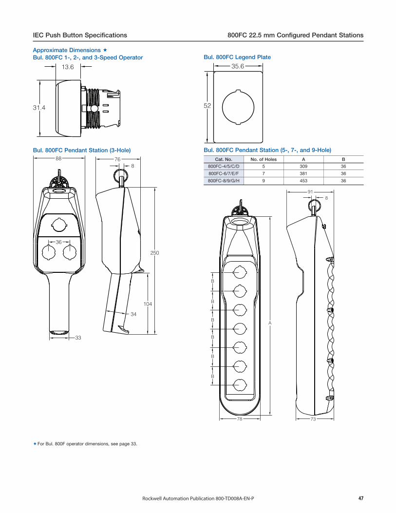
47Rockwell Automation Publication 800-TD008A-EN-P
IEC Push Button Specifications 800FC 22.5 mm Configured Pendant Stations
13.6
31.4
35.6
52
36
33
88 768
250
34
104
918
B
B
B
B
B
B
A
78 73
Cat. No. No. of Holes A B
800FC-4/5/C/D 5 309 36
800FC-6/7/E/F 7 381 36
800FC-8/9/G/H 9 453 36
For Bul. 800F operator dimensions, see page 33.
Bul. 800FC Pendant Station (5-, 7-, and 9-Hole)Bul. 800FC Pendant Station (3-Hole)
Bul. 800FC Legend PlateBul. 800FC 1-, 2-, and 3-Speed OperatorApproximate Dimensions

48 Rockwell Automation Publication 800-TD008A-EN-P
800FC 22.5 mm Configured Pendant Stations IEC Push Button Specifications
Order/Item __________________________________
Cat. No. 800F-36VE100K
Vertical Mounting
Cat. No. 800F-36HE100K
Cat. No. 800F-36HE100S
Cat. No. 800F-36HE100L
Horizontal Mounting
Cat. No. 800F-36VE100S
Cat. No. 800F-36VE100L
Custom Text Fax/Scan Sheet
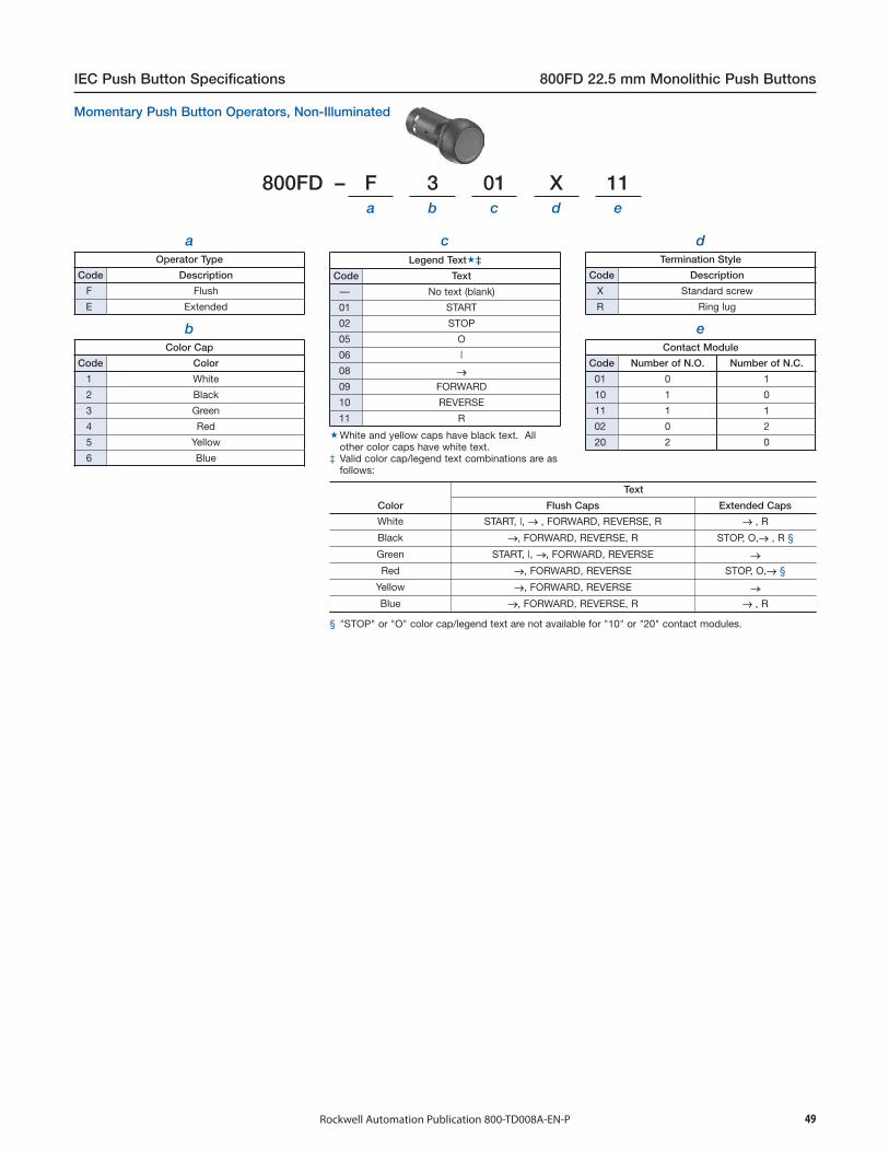
49Rockwell Automation Publication 800-TD008A-EN-P
IEC Push Button Specifications 800FD 22.5 mm Monolithic Push Buttons
800FD – F 3 01 X 11a b c d e
aOperator Type
Code Description
F Flush
E Extended
bColor Cap
Code Color
1 White
2 Black
3 Green
4 Red
5 Yellow
6 Blue
cLegend Text‡
Code Text
— No text (blank)
01 START
02 STOP
05 O
06 |
08 →09 FORWARD
10 REVERSE
11 R
dTermination Style
Code Description
X Standard screw
R Ring lug
eContact Module
Code Number of N.O. Number of N.C.
01 0 1
10 1 0
11 1 1
02 0 2
20 2 0
Color
Text
Flush Caps Extended Caps
White START, |, → , FORWARD, REVERSE, R → , R
Black →, FORWARD, REVERSE, R STOP, O,→ , R §
Green START, |, →, FORWARD, REVERSE →Red →, FORWARD, REVERSE STOP, O,→ §
Yellow →, FORWARD, REVERSE →Blue →, FORWARD, REVERSE, R → , R
§ "STOP" or "O" color cap/legend text are not available for "10" or "20" contact modules.
White and yellow caps have black text. Allother color caps have white text.
‡ Valid color cap/legend text combinations are asfollows:
Momentary Push Button Operators, Non-Illuminated
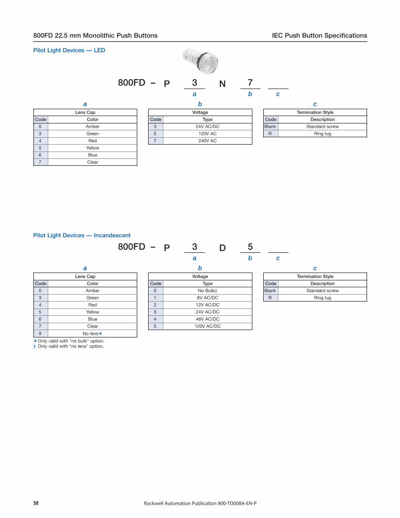
50 Rockwell Automation Publication 800-TD008A-EN-P
800FD 22.5 mm Monolithic Push Buttons IEC Push Button Specifications
800FD – P 3 N 7a b c
aLens Cap
Code Color
0 Amber
3 Green
4 Red
5 Yellow
6 Blue
7 Clear
bVoltage
Code Type
3 24V AC/DC
5 120V AC
7 240V AC
800FD – P 3
cTermination Style
Code Description
Blank Standard screw
R Ring lug
D 5a b c
aLens Cap
Code Color
0 Amber
3 Green
4 Red
5 Yellow
6 Blue
7 Clear
9 No lens
bVoltage
Code Type
0 No Bulb‡
1 6V AC/DC
2 12V AC/DC
3 24V AC/DC
4 48V AC/DC
5 120V AC/DC
Only valid with "no bulb" option.‡ Only valid with "no lens" option.
Pilot Light Devices — Incandescent
Pilot Light Devices — LED
cTermination Style
Code Description
Blank Standard screw
R Ring lug
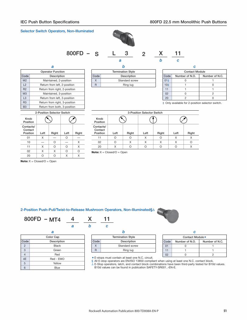
51Rockwell Automation Publication 800-TD008A-EN-P
IEC Push Button Specifications 800FD 22.5 mm Monolithic Push Buttons
800FD – S L 3 2 X 11a b c
aOperator Function
Code Description
M2 Maintained, 2-position
L2 Return from left, 2-position
R2 Return from right, 2-position
M3 Maintained, 3-position
L3 Return from left, 3-position
R3 Return from right, 3-position
B3 Return from both, 3-position
bTermination Style
Code Description
X Standard screw
R Ring lug
cContact Module
Code Number of N.O. Number of N.C.
01‡ 0 1
10‡ 1 0
11 1 1
02 0 2
20 2 0
2-Position Selector Switch
KnobPosition
Contacts/ContactPosition Left Right Left Right
01 X — O —
10 — O — X
11 X O O X
02 X X O O
20 O O X X
Note: X = Closed/O = Open
3-Position Selector Switch
KnobPosition
Contacts/ContactPosition Left Right Left Right Left Right
11 O O X O X X
02 O X X X X O
20 X O O O O X
Note: X = Closed/O = Open
800FD – MT4 4 X 11a b c
aColor Cap
Code Description
2 Black
3 Green
4 Red
4E Red - EMO
5 Yellow
6 Blue
bTermination Style
Code Description
X Standard screw
R Ring lug
cContact Module
Code Number of N.O. Number of N.C.
01 0 1
11 1 1
02 0 2E-stops must contain at least one N.C. circuit.§ All E-stop operators are EN/ISO 13850 compliant when using at least one N.C. contact block.∆ E-Stop operators, latch, and contact block combinations have been third-party tested for B10d values.
B10d values can be found in publication SAFETY-SR001_-EN-E.
2-Position Push-Pull/Twist-to-Release Mushroom Operators, Non-Illuminated§∆
‡ Only available for 2-position selector switch.
Selector Switch Operators, Non-Illuminated

52 Rockwell Automation Publication 800-TD008A-EN-P
800FD 22.5 mm Monolithic Push Buttons IEC Push Button Specifications
Mechanical Ratings
Vibration (assembled to panel) Tested at 10…2000 Hz, 1.52 mm displacement (peak-to-peak) max./10 G max. for 3 hr duration, nodamage
Shock Tested at 1/2 cycle sine wave for 11 ms; no damage at 100 G
Degree of protection IP66 (Type 3/3R/4/4X/12/13)
Mechanical durability per EN60947-5-1 (Annex C)
300 000 cyclesSelector switch
Push-pull/twist-to-release E-stop
2 000 000 cycles Momentary push buttons
Operating forces E-stop = 36 N
Operating torque(typical application with one contact block) Selector switch = 0.25 N•m
Contact operation
N.O. Slow double make and break
N.C.
Slow double make and break -positive opening
Push button travel to changeelectrical state
N.O. 2.5 mm (0.1 in.)
N.C. 1.5 mm (0.060 in.)
Environmental
Temperature range (operating) -25…+60 °C (-13…+140 °F)‡
Temperature range (short term storage) -40…+85 °C (-40…+185 °F)
Humidity 50…95% RH from 25…60 °C (77…140 °F)
Electrical Ratings
Standard contact block ratings
B300, R300AC 15, DC 13
300 VACEN/IEC 60947-5-1 and UL 508, 17V, 5 mA min.
Nominal Voltage Range Current Draw Frequency
LED module ratings
24V AC24V DC120V AC240V AC
20…26V AC18…30V DC
102…132V AC204…264V AC
32 mA24 mA22 mA22 mA
50/60 HzDC
50/60 Hz50/60 Hz
Thermal current 5 A max. enclosed (40 °C ambient) to UL 508, EN/IEC 60947-5-1
Insulation voltage (Ui) 300V
Wire capacity (screw terminal) #18…14 AWG (0.75…2.5 mm2)Max. (2) #14 AWG, uses same size wire only
Recommendations for ring lug termination option§ 6.35 mm (0.250 in.) Max. outer diameter with 3.8 mm (0.148 in.) hole diameter
Recommended tightening torque on screw terminals 0.7…0.9 N•m (6…8 lb•in)
Dielectric strength (minimum) 2500V for one minute
External short circuit protection 5 A Type gL/gG cartridge fuse to EN 60269-2-1 or gN (Class J to UL 248-8 or Class CC to UL 248-4)
Electrical shock protection Finger-safe conforming to IP2X
Illumination
LED dominant wavelength
Green 525 nm
Red 629 nm
Yellow 590 nm
Blue 470 nm
White —
LED luminous intensity
Green 780 mcd
Red 780 mcd
Yellow 600 mcd
Blue 168 mcd
White 360 mcd
Incandescent maximum wattage 2.6 W
Performance Data — see note on page 3.‡ Operating temperatures below 0 °C (32 °F) are based on the absence of freezing moisture and liquids.§ 3M MV018-R/S (#22…18 AWG) or 3M MVU14-6R/S (#16…14 AWG)
Specifications
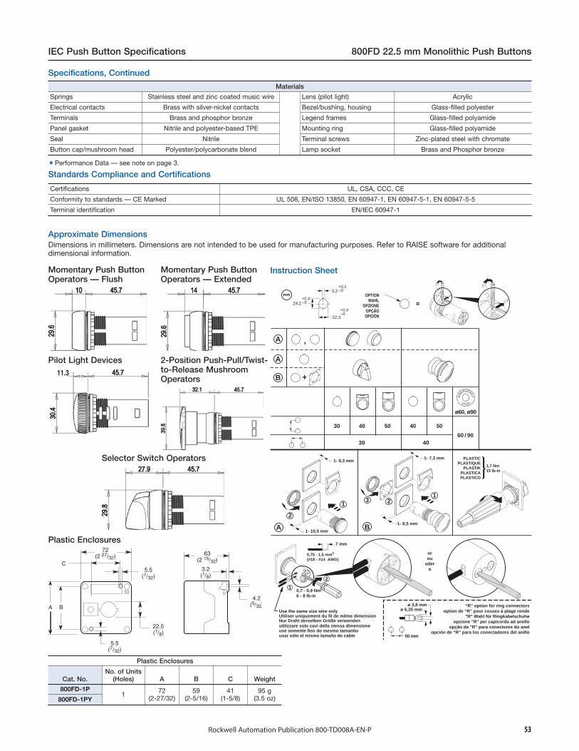
53Rockwell Automation Publication 800-TD008A-EN-P
IEC Push Button Specifications 800FD 22.5 mm Monolithic Push Buttons
Specifications, Continued
Materials
Springs Stainless steel and zinc coated music wire Lens (pilot light) Acrylic
Electrical contacts Brass with silver-nickel contacts Bezel/bushing, housing Glass-filled polyester
Terminals Brass and phosphor bronze Legend frames Glass-filled polyamide
Panel gasket Nitrile and polyester-based TPE Mounting ring Glass-filled polyamide
Seal Nitrile Terminal screws Zinc-plated steel with chromate
Button cap/mushroom head Polyester/polycarbonate blend Lamp socket Brass and Phosphor bronze
Performance Data — see note on page 3.
Certifications UL, CSA, CCC, CE
Conformity to standards — CE Marked UL 508, EN/ISO 13850, EN 60947-1, EN 60947-5-1, EN 60947-5-5
Terminal identification EN/IEC 60947-1
11.3
Plastic Enclosures
Cat. No.No. of Units
(Holes) A B C Weight
800FD-1P1 72
(2-27/32)59
(2-5/16)41
(1-5/8)95 g
(3.5 oz)800FD-1PY
30
A
B
A
4030 50
4060 / 90
ø60, ø90
40 50
24,1+0,4–0
22,3
3,2+0,2–0
+0,4–0
mm OPTIONWAHL
OPZIONEOPÇÃO
OPCIÓN
=
PLASTICPLASTIQUE
PLASTIKPLASTICAPLÁSTICO
B
A
2
3 2
2
1
1
+
,
EM
ERGENCY
S T O P
1
0,7 - 0,9 Nm6 - 8 lb-in
1,7 Nm15 lb-in
1- 10,5 mm
1- 7,3 mm1- 9,3 mm
1- 8,5 mm
7 mm
0,75 - 1,5 mm2
(#18 - #14 AWG)
ø 6,35 mm
50 mm
ø 3,8 mm “R” option for ring connectorsoption de “R” pour cosses à plage ronde
"R" Wahl für Ringkabelschuheopzione "R" per capicorda ad anello
opção de "R" para conectores do anelopción de “R” para los conectadores del anillo
Use the same size wire onlyUtiliser uniquement du fil de même dimension
usar sólo el mismo tamaño de cable
Nur Draht derselben Größe verwendenutilizzare solo cavi della stessa dimensioneuse somente fios do mesmo tamanho
orou
odero
Standards Compliance and Certifications
Dimensions in millimeters. Dimensions are not intended to be used for manufacturing purposes. Refer to RAISE software for additionaldimensional information.
Approximate Dimensions
Instruction Sheet
Plastic Enclosures
2-Position Push-Pull/Twist-to-Release MushroomOperators
Selector Switch Operators
Pilot Light Devices
Momentary Push ButtonOperators — Extended
Momentary Push ButtonOperators — Flush

54 Rockwell Automation Publication 800-TD008A-EN-P
800B 16 mm Push Buttons IEC Push Button Specifications
Mechanical Ratings
Vibration (assembled to panel) Tested at 10…2000 Hz, 1.52 mm displacement (peak-to-peak) max./10 G max. for 6 hr duration, no damage
Shock Tested at 1/2 cycle sine wave for 11 ms; no damage at 100 G
Degree of protection‡ IP66, Type 4/4X/13
Mechanical durability perEN 60947-5-1 (Annex C)
2 000 000 Cycles Push buttons – momentary
1 000 000 Cycles Push buttons – maintained
250 000 Cycles Selector switch
200 000 Cycles Key selector switch
200 000 Cycles Twist-to-release E-stop
Operating forces (typical with one contact block) Extended = 5…8 NE-stop = 14…16 N
Operating torque(typical application with one contact block) Selector switch = 0.06 N•m (0.5 lb•in)
Mounting torque 1.1 N•m (10 lb•in)
Environmental
Temperature range (operating) -25…+55 °C (-13…+131 °F)
Temperature range (short term storage) -40…+70 °C (-40…+158 °F)
Humidity 50…95% RH from 25…60 °C (77…140 °F)
‡ Keyed selector switches do not meet 4X rating.
Mechanical Ratings — Contact Blocks
Vibration (assembled to panel) Tested at 10…2000 Hz, 1.52 mm displacement (peak-to-peak) max./10 G max. 6 hr
Shock Tested at 1/2 cycle sine wave for 11 ms and no damage at 100 G max.
Contact durability 200 000 cycles (Cat. No. 800B-PS_)
Contact operation
N.O. / N.C. Snap action
N.C.
Slow make/breakpositive opening
→N.O. Slow make/break
Push button travel to change electrical state 1.4 mm (0.06 in.)
Operating forces (typical) 1 contact block = 3 N2 contact blocks = 6 N
Electrical Ratings
Standard contact block ratings AC 15, B300, 1.5 A/240V AC, 3 A/120V ACDC 13, R300, 0.1 A/250V DC, 0.22 A/125V DC
LED Module ratings
Nominal Voltage Current Frequency
12…24V AC12…24V DC120V AC
12 mA12 mA9 mA
50/60 HzDC
50/60 Hz
Thermal current Ith = 5 A (AC), Ith = 1 A (DC)
Insulation voltage (Ui) 300V
Stab termination 2.8 X 0.5 mm
Dielectric strength (minimum) 1500V 1 min.
External short circuit protection – standardblocks 6 A type gL/gG cartridge fuse to EN 60269-2-1 or gN (Class J to UL 248-8 or Class C to UL 248-4)
Electrical shock protection Finger-safe conforming to IP2X
Illumination
LED Dominant wavelengthGreenRedWhite
525 nm624 nm
—
LED Luminous intensityGreenRedWhite
500 mcd400 mcd1000 mcd
Incandescent maximum wattage 1.2 W
Materials
Springs Stainless steel and gold-plated, high-carbon steel
Electrical contacts Gold-plated silver
Stab terminals Phosphor bronze withgold or nickel plating
Lenses Polycarbonate
Standards Compliance and Certifications
Specifications
Certifications UR, CSA, CCC, CE
Standards Compliance UL 508, EN ISO 13850, EN 60947-1,EN 60947-5-1, EN 60947-5-5
Terminal Identification EN/IEC 60947-1
RoHS Compliant
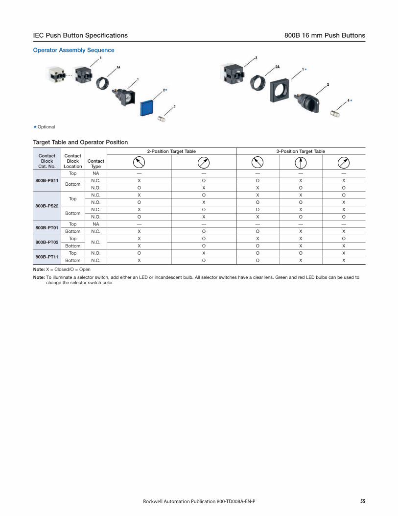
55Rockwell Automation Publication 800-TD008A-EN-P
IEC Push Button Specifications 800B 16 mm Push Buttons
ContactBlock
Cat. No.
ContactBlock
LocationContact
Type
2-Position Target Table 3-Position Target Table
800B-PS11
Top NA — — — — —
BottomN.C. X O O X X
N.O. O X X O O
800B-PS22
TopN.C. X O X X O
N.O. O X O O X
BottomN.C. X O O X X
N.O. O X X O O
800B-PT01Top NA — — — — —
Bottom N.C. X O O X X
800B-PT02Top
N.C.X O X X O
Bottom X O O X X
800B-PT11Top N.O. O X O O X
Bottom N.C. X O O X X
Note: X = Closed/O = Open
Optional
Operator Assembly Sequence
Note: To illuminate a selector switch, add either an LED or incandescent bulb. All selector switches have a clear lens. Green and red LED bulbs can be used tochange the selector switch color.
Target Table and Operator Position

56 Rockwell Automation Publication 800-TD008A-EN-P
800B 16 mm Push Buttons IEC Push Button Specifications
Round & Square Rectangle
Ø16 +0.2 -0
1.7 +0-0.1 18
15 +0.1 -0
18 24
18
Large Square Emergency Stop
24
24 40
40
Max 18.0
Max
18.
0
13.65 ±0.20
4.25 ±0.20
0.30
Max
10.
0
0.87
12.0 ±0.12
6.0 ±0.12
7.2
±0.1
2
14.4
±0.1
210 - Ø1.10
30 42.472.4
26
12.3 42.454.7
36
18
12 42.454.4
24
24
12 42.454.4
18
24
12 42.454.4
18
18
14 42.456.4
18
12 42.454.4
18
Approximate DimensionsRound
Square
Rectangle
Large Square
Emergency Stop
Hole Patterns
Printed Circuit Board Pin Socket

57Rockwell Automation Publication 800-TD008A-EN-P
IEC Push Button Specifications 800MR IEC Oiltight Operators
800MR – A 1 Aa b c d
aOperator Type
Code Description
A Flush head
B Extended head
D Mushroom head
bButton Color
Code Description
1 Green
2 Black
3 Orange
4 Grey
5 White
6 Red
7 Blue
9 Yellow
cStandard Contact Cartridges
Code Description
Blank No contacts
A 1 N.O. - 1 N.C.
A2 2 N.O.
A3 1 N.O.E.M. - 1 N.C.L.B.
A4 2 N.C.
A7 1 N.C.L.B. - 1 N.C.
B 2 N.O. - 2 N.C.
D1 1 N.O.
D2 1 N.C.
dContact Block
Termination Type‡
Code Description
Blank Stab terminals
K Large screw
Flush Head UnitCat. No. 800MR-A1B
Extended Head UnitCat. No. 800MR-B2A
Mushroom Head UnitCat. No. 800MR-D2B
Momentary Contact Push Button Units, Non-Illuminated
Guards must be orderedseparately.
‡ Logic Reed and small screwblocks can be ordered separately.
Bul. 800MR - Momentary Contact Push Buttons

58 Rockwell Automation Publication 800-TD008A-EN-P
800MR IEC Oiltight Operators IEC Push Button Specifications
800MR – PA L 24 Ra b c d e f
aOperator
Transformer
Code Description
PA Flush♦PB Extended
PMB Mushroom
Full Voltage
Code Description
QA Flush♦QB Extended
QMB Mushroom
bIllumination Options
Code Description
Blank Standard illumination as determined bypower module type
L LED§
cInput Voltage
Full Voltage
Code Description
12 12V AC/DC
24 24V AC/DC
10 120V AC♣Transformer
Code Description
16 120V AC 50/60 Hz
26 240V AC 50/60 Hz
dLens Color
Code Color
A Amber
B Blue
C Clear
G Green
R Red
W White
X No lens with contact blocks
Blank No lens without contact blocks
Flush Head UnitCat. No. 800MR-QA24GA
eStandard Contact Cartridges
Code Description
Blank No contacts
A 1 N.O. - 1 N.C.
A2 2 N.O.
A3 1 N.O.E.M. - 1 N.C.L.B.
A4 2 N.C.
A7 1 N.C.L.B. - 1 N.C.
B 2 N.O. - 2 N.C.∆D1 1 N.O.
D2 1 N.C.
fContact Block
Termination Type♠Code Description
Blank Stab terminals
K Large screw
Extended Head UnitCat. No. 800MR-PB16RA
Mushroom Head UnitCat. No. 800MR-QMB24RA
§ LEDs available in red, green, amber, blue, and white. LED color must match lens color, except clear lens supplied withwhite LED and white lens supplied with amber LED.
♣ Only available with LED Illumination option.∆ Only available with full voltage power module option and standard stab terminations.♦ Guards must be ordered separately.♠ Logic Reed and small screw blocks must be ordered separately.
Momentary Contact Push Button Units, llluminated
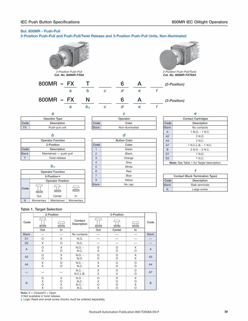
59Rockwell Automation Publication 800-TD008A-EN-P
IEC Push Button Specifications 800MR IEC Oiltight Operators
800MR – FX T 6 Aa b c d e f
800MR – FX N 6 Aa b1 c d e f
aOperator Type
Code Description
FX Push-pull unit
b1
Operator Function
3-Position
bOperator Function
2-Position
Code Description
Blank Maintained — push-pull
T Twist-release
Code
Operator Position
Out Center In
N Momentary Maintained Momentary
cOperator
Code Color
Blank Non-illuminated
dButton Color
Code Color
1 Green
2 Black
3 Orange
4 Grey
5 White
6 Red
7 Blue
9 Yellow
Blank No cap
eContact Cartridges
Code Description
Blank No contacts
A 1 N.O. - 1 N.C.
A2 2 N.O.
A4 2 N.C.
A7 1 N.C.L.B. - 1 N.C.
B 2 N.O. - 2 N.C.
D1 1 N.O.
D2 1 N.C.
Note: See Table 1 for Target description.
fContact Block Termination Type‡
Code Description
Blank Stab terminals
K Large screw
2-Position Push-PullCat. No. 800MR-FX6A
2-Position Push-Pull/TwistCat. No. 800MR-FXT6A4
Note: X = Closed/O = OpenNot available in twist release.‡ Logic Reed and small screw blocks must be ordered separately.
Code
2-Position
ContactDescription
3-Position
Code
Out In Out Center In
Blank — — No contacts — — — Blank
D1 O X N.O. — — — —
D2 X O N.C. — — — —
A OX
XO
N.O. -N.C.
OX
OO
XO A
A2 OO
XX
N.O. -N.O.
OO
OO
XX A2
A4 XX
OO
N.C. -N.C.
XX
OO
OO A4
— — — N.C. -N.C.L.B.
XX
OX
OO A7
B
OXOX
XOXO
N.O. -N.C.
N.O. -N.C.
OXOX
OOOO
XOXO
B
Table 1. Target Selection
2-Position Push-Pull and Push-Pull/Twist Release and 3-Position Push-Pull Units, Non-Illuminated
(3-Position)
(2-Position)
Bul. 800MR - Push-Pull

60 Rockwell Automation Publication 800-TD008A-EN-P
800MR IEC Oiltight Operators IEC Push Button Specifications
Illuminated 2-Position Push-PullCat. No. 800MR-FXQ24RA
Illuminated 2-Position Push-Pull/TwistCat. No. 800MR-FXTP16RA
aOperator Type
Code Description
FX Push-pull unit
bOperator Function
2-Position
Code Description
Blank Maintained
T Twist-release
cOperator Type
Code Description
P Transformer
b1
Operator Function
3-Position
Code
Operator Position
Out Center In
N Momentary Maintained Momentary
Q Full voltage
dIllumination Options
Code Description
Blank Incandescent lamp
L LED‡
eVoltage
Full Voltage
Code Description
12 12V AC/DC
24 24V AC/DC
10 120V AC§
Transformer
Code Description
16 120V AC 50/60 Hz
26 240V AC 50/60 Hz
fButton Color
Code Color
A Amber
B Blue
C Clear
G Green
R Red
W White
X No cap
gContact Cartridges
Code Description
Blank No contacts
A 1 N.O. - 1 N.C.
A2 2 N.O.
A4 2 N.C.
A7 1.N.C.L.B. - 1 N.C.
B 2 N.O. - 2 N.C.♣D1 1 N.O.
D2 1 N.C.
Note: See Table 1 for Target description.
hContact Block Termination Type∆
Code Description
Blank Stab terminals
K Large screw
Code
2-Position
ContactDescription
3-Position
Code
Out In Out Center In
Blank — — No contacts — — — Blank
D1 O X N.O. — — — —
D2 X O N.C. — — — —
A OX
XO
N.O. -N.C.
OX
OO
XO A
A2 OO
XX
N.O. -N.O.
OO
OO
XX A2
A4 XX
OO
N.C. -N.C.
XX
OO
OO A4
— — — N.C. -N.C.L.B.
XX
OX
OO A7
B
OXOX
XOXO
N.O. -N.C.
N.O. -N.C.
OXOX
OOOO
XOXO
B
800MR – FX T P 16 R Aa b c d e f g h
(3-Position)
(2-Position)
Note: X = Closed/O = OpenNot available in twist release.‡ LEDs available in red, green, amber, blue, and white. LED color must match lens color, except clear lens supplied with white LED and white lens supplied with
amber LED.§ Only available with LED Illumination option.♣ Only available with full voltage power module option and standard stab terminations.∆ Logic Reed and small screw blocks must be ordered separately.
Table 2. Target Selection
2-Position Push-Pull and Push-Pull/Twist Release and 3-Position Push-Pull Units, Illuminated
800MR – FX N P 16 R Aa b1 c d e f g h

61Rockwell Automation Publication 800-TD008A-EN-P
IEC Push Button Specifications 800MR IEC Oiltight Operators
Standard Knob OperatorCat. No. 800MR-HH2BLA
Knob Lever OperatorCat. No. 800MR-HK2BLA
bOperator Color and Type§
aOperator Positions
Code Description
H 2-position selector switch
H 2-position cylinder lock
Standard Knob
Code Description
X No knob
H Black
Knob Lever
Code Description
X No knob lever
K Black
Cylinder Lock
Code Description
Blank Key
cOperator Function
Standard Knob
Code Description
2 Maintained
4 Spring return from left
5 Spring return from right
c1
Operator Function/Locking Position
Maintained
Code Description
31 Lock in left
32 Lock in right
33 Lock in both
Spring Return From Left
Code Description
42 Lock in right
Spring Return From Right
Code Description
48 Lock in left
dCam Type
Code
c2
Key Codes‡
Code Key No. Master Key
Blank T100 (standard) 1T
02 T101 1T
03 T102 1T
04 T106 1T
05 T107 1T
07 T109 2T
08 T134 2T
09 T135 2T
10 T136 2T
14 T147 2T
Description
B B cam
eContact Cartridge Position
Code Description
Blank Both left and right
L Left
e1
Contact Cartridges
Code Description
Blank No contacts
∆ A 1 N.O. - 1 N.C.
∆ A2 2 N.O.
∆ A4 2 N.C.
♦ B 2 N.O. - 2 N.C.
∆ D1 1 N.O.
∆ D2 1 N.C.
♦ P1 3 N.O.
♦ P2 3 N.C.
♦ P3 2 N.O. - 1 N.C.
♦ P4 2 N.C. - 1 N.O.
♦ P5 4 N.O.
♦ P6 4 N.C.
♦ P7 3 N.O. - 1 N.C.
♦ P8 1 N.O. - 3 N.C.
Note: See Table 1 for Target arrangements
Cam Description (2-Position)
Target
fContact Block Termination Type♣
Code Description
Blank Stab terminals
K Large screw
Operator Function
Maintained and SpringReturned From Right
Spring ReturnedFrom Left
X O N.C. N.O.
O X N.O. N.C.
Note: X = Closed/O = OpenKey removable in locked position only.‡ If no optional key code is specified, the standard key (T100) will be supplied.§ Red, green, blue, yellow, orange, grey, and white non-illuminated selector switch knobs and lever knobs
must be ordered separately.♣ Logic Reed and small screw contact blocks must be ordered separately.∆ Contact cartridge position code (Table e) must be L.♦ Contact cartridge position code (Table e) must be --.
800MR – H H 2 B L Aa b c d e e1 f
800MR – H 31 B L Aa b c1 c2 d e e1 f
(Cylinder Lock)
(Selector Switch)
Table 1. Selector Switch Cam Targets
2-Position Selector Switch Units, Non-IlluminatedBul. 800MR - Selector Switches
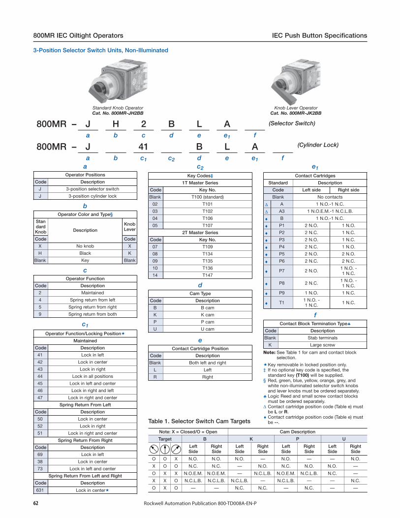
62 Rockwell Automation Publication 800-TD008A-EN-P
800MR IEC Oiltight Operators IEC Push Button Specifications
3-Position Selector Switch Units, Non-Illuminated
Standard Knob OperatorCat. No. 800MR-JH2BB
Knob Lever OperatorCat. No. 800MR-JK2BB
aOperator Positions
Code Description
J 3-position selector switch
J 3-position cylinder lock
bOperator Color and Type§
StandardKnob Description
KnobLever
Code Code
X No knob X
H Black K
Blank Key Blank
cOperator Function
Code Description
2 Maintained
4 Spring return from left
5 Spring return from right
9 Spring return from both
c1
Operator Function/Locking Position
Maintained
Code Description
41 Lock in left
42 Lock in center
43 Lock in right
44 Lock in all positions
45 Lock in left and center
46 Lock in right and left
47 Lock in right and center
Spring Return From Left
Code Description
50 Lock in center
52 Lock in right
51 Lock in right and center
Spring Return From Right
Code Description
69 Lock in left
38 Lock in center
73 Lock in left and center
Spring Return From Left and Right
Code Description
631 Lock in center
c2
Key Codes‡
1T Master Series
Code Key No.
Blank T100 (standard)
02 T101
03 T102
04 T106
05 T107
2T Master Series
Code Key No.
07 T109
08 T134
09 T135
10 T136
14 T147
e
dCam Type
Code Description
B B cam
K K cam
P P cam
U U cam
Contact Cartridge Position
Code Description
Blank Both left and right
L Left
R Right
e1
Contact Cartridges
Standard Description
Code Left side Right side
Blank No contacts
∆ A 1 N.O.-1 N.C.
∆ A3 1 N.O.E.M.-1 N.C.L.B.
♦ B 1 N.O.-1 N.C.
♦ P1 2 N.O. 1 N.O.
♦ P2 2 N.C. 1 N.C.
♦ P3 2 N.O. 1 N.C.
♦ P4 2 N.C. 1 N.O.
♦ P5 2 N.O. 2 N.O.
♦ P6 2 N.C. 2 N.C.
♦ P7 2 N.O. 1 N.O. -1 N.C.
♦ P8 2 N.C. 1 N.O. -1 N.C.
♦ P9 1 N.O. 1 N.C.
♦ T1 1 N.O. -1 N.C. 1 N.C.
fContact Block Termination Type♣
Code Description
Blank Stab terminals
K Large screw
Note: See Table 1 for cam and contact blockselection.
Key removable in locked position only.‡ If no optional key code is specified, the
standard key (T100) will be supplied.§ Red, green, blue, yellow, orange, grey, and
white non-illuminated selector switch knobsand lever knobs must be ordered separately.
♣ Logic Reed and small screw contact blocksmust be ordered separately.
∆ Contact cartridge position code (Table e) mustbe L or R.
♦ Contact cartridge position code (Table e) mustbe --.Table 1. Selector Switch Cam Targets
Note: X = Closed/O = Open Cam Description
Target B K P U
LeftSide
RightSide
LeftSide
RightSide
LeftSide
RightSide
LeftSide
RightSide
O O X N.O. N.O. N.O. — N.O. — — N.O.
X O O N.C. N.C. — N.O. N.C. N.O. N.O. —
O X X N.O.E.M. N.O.E.M. — N.C.L.B. N.O.E.M. N.C.L.B. N.C. —
X X O N.C.L.B. N.C.L.B. N.C.L.B. — N.C.L.B. — — N.C.
O X O — — N.C. N.C. — N.C. — —
800MR – J H 2 B L Aa b c d e e1 f
(Selector Switch)
800MR – J 41 B L Aa b c1 c2 d e e1 f
(Cylinder Lock)

63Rockwell Automation Publication 800-TD008A-EN-P
IEC Push Button Specifications 800MR IEC Oiltight Operators
4-Position Selector Switch Units, Non-Illuminated
Standard Knob OperatorCat. No. 800MR-NH2QB
Knob Lever OperatorCat. No. 800MR-NK2QB
aOperator Positions
Code Description
N 4-position selector
N 4-position cylinder lock
bOperator Color and Type♣
StandardKnob Description
KnobLever
Code Code
X No knob X
H Black K
Blank Key Blank
cOperator Function‡
Code Description
2 Maintained
c1
Operator Function/Locking Position
Standard Key
Code Description
31 Lock in position 1
32 Lock in position 2
33 Lock in position 3
34 Lock in position 4
41 Lock in position 1-2
42 Lock in position 1-3
43 Lock in position 1-4
44 Lock in position 2-3
45 Lock in position 2-4
46 Lock in position 3-4
51 Lock in position 1-2-3
52 Lock in position 1-2-4
53 Lock in position 1-3-4
54 Lock in position 2-3-4
61 Lock in all positions
c2
Key Codes§
Code Key No. Master Key
Blank T100 (standard) 1T
02 T101 1T
03 T102 1T
04 T106 1T
05 T107 1T
07 T109 2T
08 T134 2T
09 T135 2T
10 T136 2T
14 T147 2T
dCam Type and Target Table
Q
Target Contact Type(Rear View)
Left Right
O O O X 1 N.O. —
O O X O 1 N.C. —
O X O O — 1 N.O.
X O O O — 1 N.C.
Note: X = Closed/O = Open
eContact Cartridges
Standard Block/Stab Terminations
Code Description
Blank No contacts
B 2 N.O. - 2 N.C.
fContact Block Termination Type∆
Code Description
Blank Stab terminals
K Large screw
♣ Red, green, blue, yellow, orange, grey, andwhite non-illuminated selector switch knobsand knob levers must be ordered separately.
Key removable in locked position only.‡ Operators are maintained in all positions.§ If no optional key code is specified, the
standard key (T100) will be supplied.∆ Logic Reed and small screw contact blocks
must be ordered separately.
800MR – N H 2 Q Ba b c d e f
(Selector Switch)
800MR N 31 Q Ba b c1 c2 d e f
(Cylinder Lock)
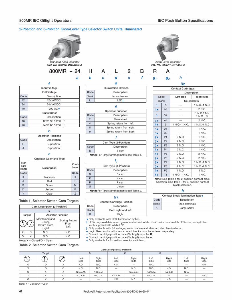
64 Rockwell Automation Publication 800-TD008A-EN-P
800MR IEC Oiltight Operators IEC Push Button Specifications
Standard Knob OperatorCat. No. 800MR-24HA2BRA
Knob Lever OperatorCat. No. 800MR-24HL2BRA
aInput Voltage
Full Voltage
Code
800MR – 24 H A L 2 B R Aa b c d e f g1 g2 h
Description
12 12V AC/DC
24 24V AC/DC
10 120V AC
Transformer
Code Description
16 120V AC 50/60 Hz
26 240V AC 50/60 Hz
bOperator Positions
Code Description
H 2-position
J 3-position
cOperator Color and Type
StandardKnob Description
KnobLever
Code Code
X No knob X
A Red L
B Green M
D Amber P
Y Clear Z
dIllumination Options
Code Description
Blank Incandescent
L LED‡
eOperator Function
Code Description
2 Maintained
4 Spring return from left
5 Spring return from right
9 Spring return from both
fCam Type (2-Position)
Code Description
B B cam
Note: For Target arrangements see Table 1.
f1Cam Type (3-Position)
Code Description
B B cam
K K cam
P P cam
U U cam
Note: For Target arrangements see Table 2.
g1
Contact Cartridge Position
Code Description
Blank Both right and left
R Right
g2
Contact Cartridges
Description
Code Left side Right side
Blank No contacts
∆ A — 1 N.O.-1 N.C.
∆♠ A2 — 2 N.O.
∆ A3 — 1 N.O.E.M.-1 N.C.L.B.
∆♠ A4 — 2 N.C.
§♦ B 1 N.O.-1 N.C. 1 N.O.-1 N.C.
∆♠ D1 — 1 N.O.
∆♠ D2 — 1 N.C.
§♦ P1 2 N.O. 1 N.O.
§♦ P2 2 N.C. 1 N.C.
§♦ P3 2 N.O. 1 N.C.
§♦ P4 2 N.C. 1 N.O.
§♦ P5 2 N.O. 2 N.O.
§♦ P6 2 N.C. 2 N.C.
§♦ P7 2 N.O. 1 N.O.-1 N.C.
§♦ P8 2 N.C. 1 N.O.-1 N.C.
§♦ P9 1 N.O. 1 N.C
§♦ T1 1 N.O.-1 N.C. 1 N.C.
Note: See Table 1 for 2-position contact blockselection. See Table 2 for 3-position contact
block selection.
hContact Block Termination Type♣
Code Description
Blank Stab terminals
K Large screw
Note: X = Closed/O = Open
Cam Description (3-Position)
Target B K P
Cam Description (2-Position)
B
Target Operator Function
Maintained andSpring
Return FromRight
Spring ReturnFromLeft
X O N.C. N.O.
O X N.O. N.C.
U
LeftSide
RightSide
LeftSide
RightSide
LeftSide
RightSide
LeftSide
RightSide
O O X N.O. N.O. N.O. — N.O. — — N.O.
X O O N.C. N.C. — N.O. N.C. N.O. N.O. —
O X X N.O.E.M. N.O.E.M. — N.C.L.B. N.O.E.M. N.C.L.B. N.C. —
X X O N.C.L.B. N.C.L.B. N.C.L.B. — N.C.L.B. — — N.C.
O X O — — N.C. N.C. — N.C. — —
Note: X = Closed/O = Open
Table 2. Selector Switch Cam Targets
Table 1. Selector Switch Cam Targets
Only available with LED Illumination option.‡ LEDs only available in red, green, amber and white. Knob color must match LED color, except clear
knob supplied with white LED.§ Only available with full voltage power module and standard stab terminations.♣ Logic Reed and small screw contact blocks must be ordered separately.∆ Contact cartridge position code (Table g1) must be R.♦ Contact cartridge position code (Table g1) must be --.♠ Only available for 2-position selector switches.
2-Position and 3-Position Knob/Lever Type Selector Switch Units, Illuminated
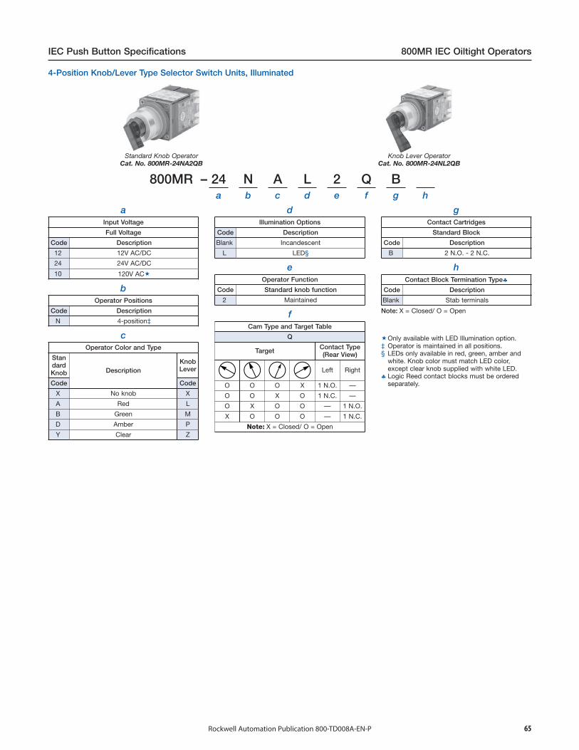
65Rockwell Automation Publication 800-TD008A-EN-P
IEC Push Button Specifications 800MR IEC Oiltight Operators
Standard Knob OperatorCat. No. 800MR-24NA2QB
Knob Lever OperatorCat. No. 800MR-24NL2QB
a
800MR – 24 N A L 2 Q Ba b c d e f g h
Input Voltage
Full Voltage
Code Description
12 12V AC/DC
24 24V AC/DC
10 120V AC
bOperator Positions
Code Description
N 4-position‡
cOperator Color and Type
StandardKnob Description
KnobLever
Code Code
X No knob X
A Red L
B Green M
D Amber P
Y Clear Z
dIllumination Options
Code Description
Blank Incandescent
L LED§
eOperator Function
Code Standard knob function
2 Maintained
fCam Type and Target Table
Q
Target Contact Type(Rear View)
Left Right
O O O X 1 N.O. —
O O X O 1 N.C. —
O X O O — 1 N.O.
X O O O — 1 N.C.
Note: X = Closed/ O = Open
gContact Cartridges
Standard Block
Code Description
B 2 N.O. - 2 N.C.
hContact Block Termination Type♣
Code Description
Blank Stab terminals
Only available with LED Illumination option.‡ Operator is maintained in all positions.§ LEDs only available in red, green, amber and
white. Knob color must match LED color,except clear knob supplied with white LED.
♣ Logic Reed contact blocks must be orderedseparately.
Note: X = Closed/ O = Open
4-Position Knob/Lever Type Selector Switch Units, Illuminated
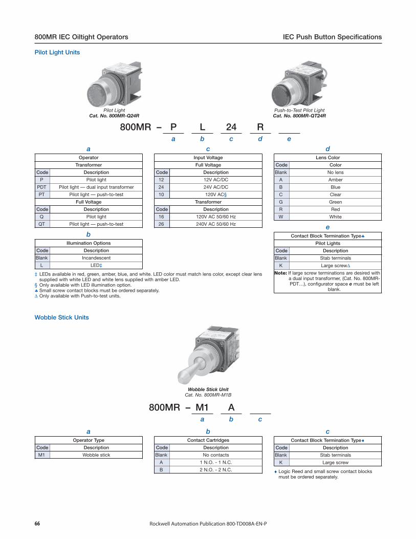
66 Rockwell Automation Publication 800-TD008A-EN-P
800MR IEC Oiltight Operators IEC Push Button Specifications
Pilot LightCat. No. 800MR-Q24R
Push-to-Test Pilot LightCat. No. 800MR-QT24R
aOperator
Transformer
Code Description
P Pilot light
PDT Pilot light — dual input transformer
PT Pilot light — push-to-test
Full Voltage
Code Description
Q Pilot light
QT Pilot light — push-to-test
bIllumination Options
Code Description
Blank Incandescent
L LED‡
cInput Voltage
Full Voltage
Code Description
12 12V AC/DC
24 24V AC/DC
10 120V AC§
Transformer
Code Description
16 120V AC 50/60 Hz
26 240V AC 50/60 Hz
dLens Color
Code Color
Blank No lens
A Amber
B Blue
C Clear
G Green
R Red
W White
Wobble Stick UnitCat. No. 800MR-M1B
eContact Block Termination Type♣
Pilot Lights
Code Description
Blank Stab terminals
K Large screw∆Note: If large screw terminations are desired with
a dual input transformer, (Cat. No. 800MR-PDT…), configurator space e must be left
blank.
800MR – P L 24 Ra b c d e
caOperator Type
Code Description
M1
800MR – M1 Aa b c
Wobble stick
Contact Block Termination Type♦Code Description
Blank Stab terminals
K
bContact Cartridges
Code Description
Blank No contacts
A 1 N.O. - 1 N.C.
B 2 N.O. - 2 N.C.
Large screw
♦ Logic Reed and small screw contact blocksmust be ordered separately.
Wobble Stick Units
‡ LEDs available in red, green, amber, blue, and white. LED color must match lens color, except clear lenssupplied with white LED and white lens supplied with amber LED.
§ Only available with LED illumination option.♣ Small screw contact blocks must be ordered separately.∆ Only available with Push-to-test units.
Pilot Light Units

67Rockwell Automation Publication 800-TD008A-EN-P
IEC Push Button Specifications 800MB IEC Oiltight Operators
Flush Head UnitCat. No. 800MB-CA1B
Extended Head UnitCat. No. 800MB-CB1B
800 MB – CA 1 Aa b c d e
aBezel Color‡
Code Color
MB Black
bOperator Type
Code Description
CA Flush head
CB Extended head
cColor Insert
Code Color
X No color insert
1 Green
3 Orange
4 Grey
5 White
6 Red
7 Blue
9 Yellow
dContact Block(s)
Standard
Code Description
Blank No contacts
D1 1 N.O.
D2 1 N.C.
A 1 N.O. - 1 N.C.
A2 2 N.O.
A4 2 N.C.
A7 1 N.C.L.B. - 1 N.C.
B 2 N.O. - 2 N.C.
eContact Block Termination Type§
Code Description
Blank Stab terminals
K Large screw
Red flush head must be ordered separately.‡ Grey bezel can be ordered separately.§ Logic Reed and small screw contact blocks must be ordered separately.
Momentary Contact Push Button Units, Non-IlluminatedBul. 800MB
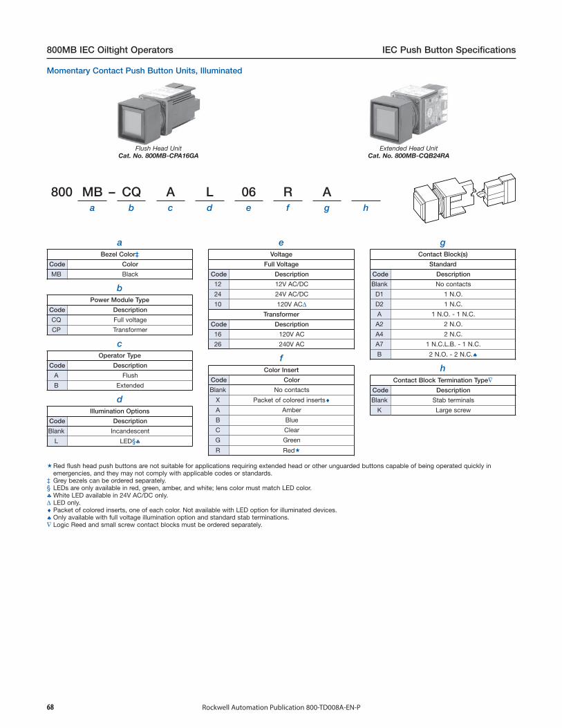
68 Rockwell Automation Publication 800-TD008A-EN-P
800MB IEC Oiltight Operators IEC Push Button Specifications
Flush Head UnitCat. No. 800MB-CPA16GA
Extended Head UnitCat. No. 800MB-CQB24RA
800 MB – CQ A L 06 R Aa b c d e f g h
aBezel Color‡
Code Color
MB Black
bPower Module Type
Code Description
CQ Full voltage
CP Transformer
cOperator Type
Code Description
A Flush
B Extended
dIllumination Options
Code Description
Blank Incandescent
L LED§♣
eVoltage
Full Voltage
Code Description
12 12V AC/DC
24 24V AC/DC
10 120V AC∆Transformer
Code Description
16 120V AC
26 240V AC
fColor Insert
Code Color
Blank No contacts
X Packet of colored inserts♦A Amber
B Blue
C Clear
G Green
R Red
gContact Block(s)
Standard
Code Description
Blank No contacts
D1 1 N.O.
D2 1 N.C.
A 1 N.O. - 1 N.C.
A2 2 N.O.
A4 2 N.C.
A7 1 N.C.L.B. - 1 N.C.
B 2 N.O. - 2 N.C.♠
Red flush head push buttons are not suitable for applications requiring extended head or other unguarded buttons capable of being operated quickly inemergencies, and they may not comply with applicable codes or standards.
‡ Grey bezels can be ordered separately.§ LEDs are only available in red, green, amber, and white; lens color must match LED color.♣ White LED available in 24V AC/DC only.∆ LED only.♦ Packet of colored inserts, one of each color. Not available with LED option for illuminated devices.♠ Only available with full voltage illumination option and standard stab terminations.∇ Logic Reed and small screw contact blocks must be ordered separately.
Momentary Contact Push Button Units, Illuminated
hContact Block Termination Type∇
Code Description
Blank Stab terminals
K Large screw

69Rockwell Automation Publication 800-TD008A-EN-P
IEC Push Button Specifications 800MB IEC Oiltight Operators
Dual Operator Black BezelCat. No. 800MB-DB16B
800 MB – DB16 Ba b c d e
aBezel Color
Code Description
MB Black
bOperator Type
Code Description
DB16Dual push button unitUpper — Flush green
Lower — Extended red
cContact Blocks
Standard
Code Description
Blank No contact
B 2 N.O. - 2 N.C.
dContact Block Termination Type‡
Code Description
Blank Stab terminals
K Large screw
eLegend Options
Code Description
Blank Upper — BlankLower— Blank
50 Upper — ONLower— OFF
64 Upper — STARTLower— STOP
Grey bezels must be ordered separately.‡ Logic Reed and small screw contact blocks must be ordered separately.
Dual Operator Momentary Contact Push Button Units, Non-Illuminated
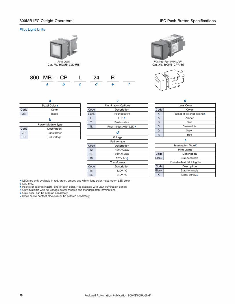
70 Rockwell Automation Publication 800-TD008A-EN-P
800MB IEC Oiltight Operators IEC Push Button Specifications
Pilot LightCat. No. 800MB-CQ24RS
Push-to-Test Pilot LightCat. No. 800MB-CPT16G
LEDs are only available in red, green, amber, and white; lens color must match LED color.§ LED only.♣ Packet of colored inserts, one of each color. Not available with LED illumination option.∆ Only available with full voltage power module and standard stab terminations.♠ Grey bezel can be ordered separately.∇ Small screw contact blocks must be ordered separately.
Pilot Light Units
800 MB – CP L 24 Ra b c d e f
aBezel Color♠
Code Color
MB Black
dVoltage
Full Voltage
Code Description
12 12V AC/DC
24 24V AC/DC
10 120V AC§
Transformer
Code Description
16 120V AC
26 240V AC
bPower Module Type
Code Description
CP Transformer
CQ Full voltage
cIllumination Options
Code Description
Blank Incandescent
L LED
T Push-to-test
TL Push-to-test with LED
eLens Color
Code Color
X Packet of colored inserts♣A Amber
B Blue
C Clear/white
G Green
R Red
fTermination Type∇
Pilot Lights
Code Description
Blank Stab terminals
Push-to-Test Pilot Lights
Code Description
Blank Stab terminals
K Large screw∆
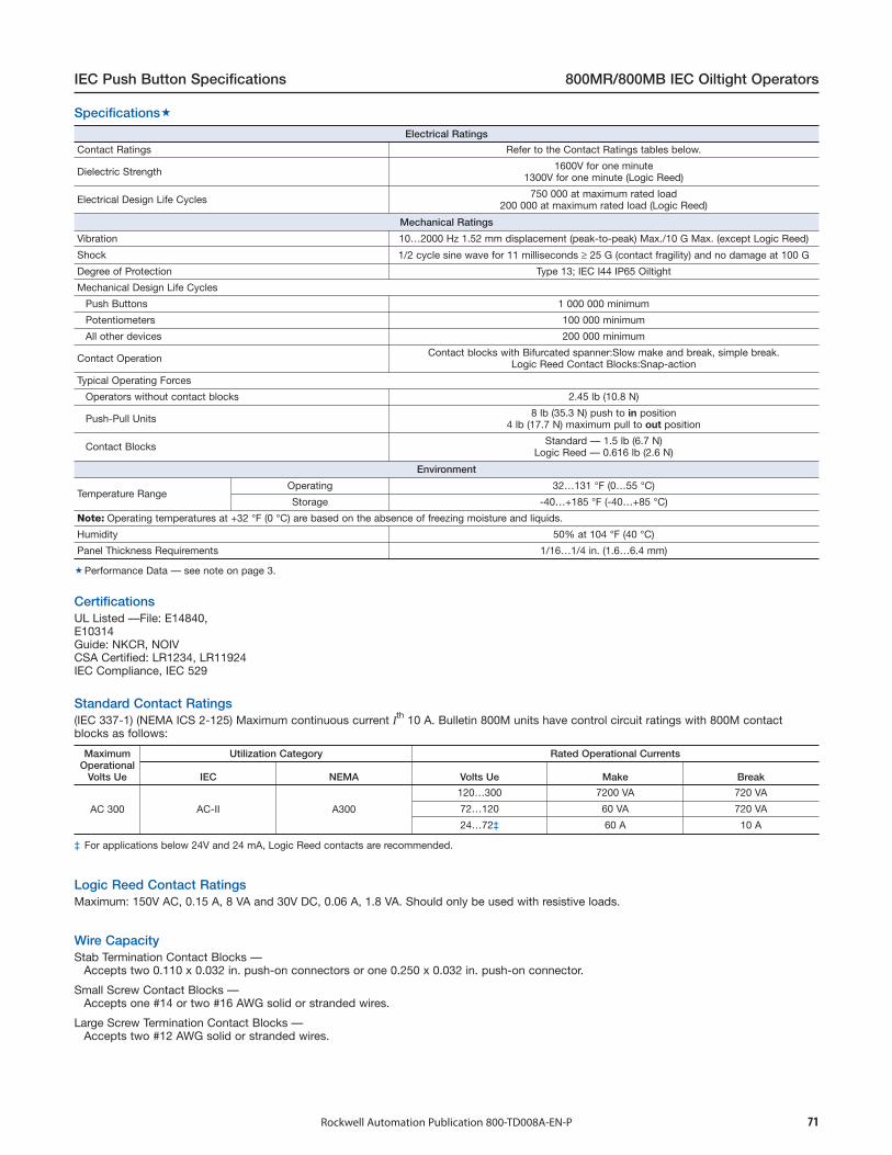
71Rockwell Automation Publication 800-TD008A-EN-P
IEC Push Button Specifications 800MR/800MB IEC Oiltight Operators
Stab Termination Contact Blocks —Accepts two 0.110 x 0.032 in. push-on connectors or one 0.250 x 0.032 in. push-on connector.
Small Screw Contact Blocks —Accepts one #14 or two #16 AWG solid or stranded wires.
Large Screw Termination Contact Blocks —Accepts two #12 AWG solid or stranded wires.
Wire Capacity
Maximum: 150V AC, 0.15 A, 8 VA and 30V DC, 0.06 A, 1.8 VA. Should only be used with resistive loads.Logic Reed Contact Ratings
(IEC 337-1) (NEMA ICS 2-125) Maximum continuous current Ith 10 A. Bulletin 800M units have control circuit ratings with 800M contactblocks as follows:
Standard Contact Ratings
Electrical Ratings
Contact Ratings Refer to the Contact Ratings tables below.
Dielectric Strength 1600V for one minute1300V for one minute (Logic Reed)
Electrical Design Life Cycles 750 000 at maximum rated load200 000 at maximum rated load (Logic Reed)
Mechanical Ratings
Vibration 10…2000 Hz 1.52 mm displacement (peak-to-peak) Max./10 G Max. (except Logic Reed)
Shock 1/2 cycle sine wave for 11 milliseconds ≥ 25 G (contact fragility) and no damage at 100 G
Degree of Protection Type 13; IEC I44 IP65 Oiltight
Mechanical Design Life Cycles
Push Buttons 1 000 000 minimum
Potentiometers 100 000 minimum
All other devices 200 000 minimum
Contact Operation Contact blocks with Bifurcated spanner:Slow make and break, simple break.Logic Reed Contact Blocks:Snap-action
Typical Operating Forces
Operators without contact blocks 2.45 lb (10.8 N)
Push-Pull Units 8 lb (35.3 N) push to in position4 lb (17.7 N) maximum pull to out position
Contact Blocks Standard — 1.5 lb (6.7 N)Logic Reed — 0.616 lb (2.6 N)
Environment
Temperature RangeOperating 32…131 °F (0…55 °C)
Storage -40…+185 °F (-40…+85 °C)
Note: Operating temperatures at +32 °F (0 °C) are based on the absence of freezing moisture and liquids.
Humidity 50% at 104 °F (40 °C)
Panel Thickness Requirements 1/16…1/4 in. (1.6…6.4 mm)
Performance Data — see note on page 3.
MaximumOperational
Volts Ue
Utilization Category Rated Operational Currents
IEC NEMA Volts Ue Make Break
AC 300 AC-II A300
120…300 7200 VA 720 VA
72…120 60 VA 720 VA
24…72‡ 60 A 10 A
‡ For applications below 24V and 24 mA, Logic Reed contacts are recommended.
Specifications
UL Listed —File: E14840,E10314Guide: NKCR, NOIVCSA Certified: LR1234, LR11924IEC Compliance, IEC 529
Certifications

72 Rockwell Automation Publication 800-TD008A-EN-P
800MR/800MB IEC Oiltight Operators IEC Push Button Specifications
ExtendeHead O
Ø Ø Ø
Round Push ButtonFlush, Extended andIlluminated Extended
Round Push ButtonIlluminated Flush
Round Push ButtonMushroom
Round Selector Switchand Potentiometerand Standard Knob
Panel WobbleStick Unit
ØØ Ø
Round Selector Switchand Potentiometer
and Wing Lever
Round Cylinder LockSelector Switch
Round Push-Pull Twist or PullRelease Units
Sq.
Guarded Bezel
Unguarded Bezel
Unit without Insertand Backlit Unit
Square Backlitwith Guarded Bezel
Square Backlitwith Unguarded Bezel
Dual Operator Unit
ExtendedHead Only
Square Push ButtonFlush and Extended
Square Push ButtonLarge Extended
Square Push ButtonDual Operator
Bul. 800MB Extension in Front of Panel
CAUTION: To avoid possible excessive heat, clusters of nine or more continuously illuminated units mounted in a small enclosure should bespaced at 1-1/2 in. (38.1 mm) minimum centers in one direction.
Bul. 800MB Front View of Square Units
Bul. 800MR Extension in Front of PanelDimensions in inches (millimeters). Dimensions are not intended to be used for manufacturing purposes.Approximate Dimensions
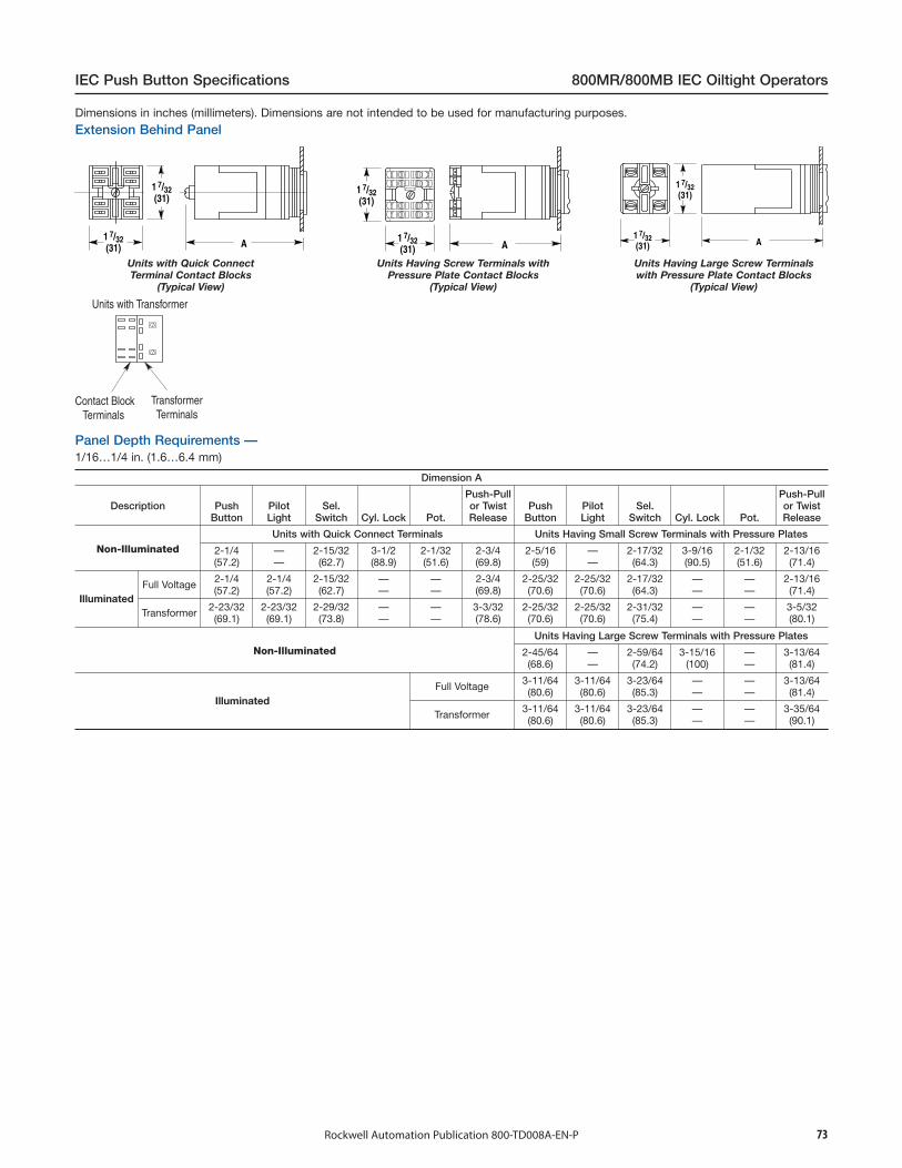
73Rockwell Automation Publication 800-TD008A-EN-P
IEC Push Button Specifications 800MR/800MB IEC Oiltight Operators
Units with Quick ConnectTerminal Contact Blocks
(Typical View)
Units Having Screw Terminals withPressure Plate Contact Blocks
(Typical View)
Units Having Large Screw Terminalswith Pressure Plate Contact Blocks
(Typical View)
Units with Transformer
Contact Block Terminals
Transformer Terminals
Dimension A
Description PushButton
PilotLight
Sel.Switch Cyl. Lock Pot.
Push-Pullor TwistRelease
PushButton
PilotLight
Sel.Switch Cyl. Lock Pot.
Push-Pullor TwistRelease
Non-IlluminatedUnits with Quick Connect Terminals Units Having Small Screw Terminals with Pressure Plates
2-1/4(57.2)
——
2-15/32(62.7)
3-1/2(88.9)
2-1/32(51.6)
2-3/4(69.8)
2-5/16(59)
——
2-17/32(64.3)
3-9/16(90.5)
2-1/32(51.6)
2-13/16(71.4)
IlluminatedFull Voltage 2-1/4
(57.2)2-1/4(57.2)
2-15/32(62.7)
——
——
2-3/4(69.8)
2-25/32(70.6)
2-25/32(70.6)
2-17/32(64.3)
——
——
2-13/16(71.4)
Transformer 2-23/32(69.1)
2-23/32(69.1)
2-29/32(73.8)
——
——
3-3/32(78.6)
2-25/32(70.6)
2-25/32(70.6)
2-31/32(75.4)
——
——
3-5/32(80.1)
Non-IlluminatedUnits Having Large Screw Terminals with Pressure Plates
2-45/64(68.6)
——
2-59/64(74.2)
3-15/16(100)
——
3-13/64(81.4)
IlluminatedFull Voltage 3-11/64
(80.6)3-11/64(80.6)
3-23/64(85.3)
——
——
3-13/64(81.4)
Transformer 3-11/64(80.6)
3-11/64(80.6)
3-23/64(85.3)
——
——
3-35/64(90.1)
1/16…1/4 in. (1.6…6.4 mm)Panel Depth Requirements —
Extension Behind PanelDimensions in inches (millimeters). Dimensions are not intended to be used for manufacturing purposes.

74 Rockwell Automation Publication 800-TD008A-EN-P
800MR/800MB IEC Oiltight Operators IEC Push Button Specifications
Preferred
Minimum VerticalSpacing
Dia.
Dia. Drill(Alternate)
Ø
Padlocking CoverCat. No. 800MR-N6
When using a padlocking cover and depending upon the types of adjacent units involved, the minimum vertical or horizontal spacing may have to be increasedfor operating clearance.
Caution: To avoid possible excessive heat, clusters of nine or more continuously illuminated units mounted in a small enclosure should be spaced at 1-1/2 in.(38.1 mm) minimum centers in one direction.
Approximate Mounting Dimensions
Shipping Weights in Ounces (kg)
Type of Unit Weight Type of Unit Weight
Push Buttons
Non-Illuminated 3-1/4 (0.09)SelectorSwitches
Non-Illuminated 4 (0.11)
IlluminatedFull Voltage 3-1/2 (0.10)
IlluminatedFull Voltage 4 (0.11)
Transformer 5 (0.14) Transformer 5-1/2 (0.16)
Pilot Lights
Pilot Light 2-1/4 (0.06)
Push-Pull Units
Non-Illuminated 4-1/2 (0.13)Push-to-Test 3 (0.09)
Pilot Light 4-1/2 (0.13)Illuminated
Full Voltage 4-1/2 (0.13)
Push-to-Test 5 (0.14) Transformer 5-1/2 (0.16)
Cylinder Lock 6 (0.17) Potentiometer Units 4 (0.11)
‡ Large screw terminal contact blocks require a minimum vertical spacing of 1-37/64 in. (40 mm); selector switches with wing lever knobs require 2-1/4 in.(57.1 mm) vertical and horizontal minimum spacing and large round legend plates require 1-1/2 in. (38.1 mm) minimum spacing.

75Rockwell Automation Publication 800-TD008A-EN-P
IEC Push Button Specifications 800MR/800MB IEC Oiltight Operators
SmallLegend Plate
LargeLegend Plate
Standard Half RoundLegend Plate
StandardLegend Plate§
Large Size‡ Round‡ Small/LargeLegend Plate
The Bulletin 800MR large half round legend plates are not recommended for use with the twist-release units because of the operator knob size. The legendplate is virtually unreadable. Push-pull units can be mounted in a 1-1/4 in. minimum horizontal spacing when no legend plate is used. Vertical spacing is1-1/2 in. when the Bulletin 800MR large half round legend plate is used.
‡ These Bulletin 800MR legend plates consist of Bulletin 800T legend plates with Cat. No. 800MR-N50 adapter rings.
Legend PlatesDimensions in inches (millimeters). Dimensions are not intended to be used for manufacturing purposes.
Allen-Bradley, Rockwell Software, Rockwell Automation, and LISTEN. THINK. SOLVE are trademarks of Rockwell Automation, Inc.
Trademarks not belonging to Rockwell Automation are property of their respective companies.
Publication 800-TD008A-EN-P - August 2014 Copyright © 2014 Rockwell Automation, Inc. All rights reserved. Printed in the U.S.A.
Important User Information
Read this document and the documents listed in the additional resources section about installation, configuration, and operation of this equipment before you install, configure, operate, or maintain this product. Users are required to familiarize themselves with installation and wiring instructions in addition to requirements of all applicable codes, laws, and standards.
Activities including installation, adjustments, putting into service, use, assembly, disassembly, and maintenance are required to be carried out by suitably trained personnel in accordance with applicable code of practice.
If this equipment is used in a manner not specified by the manufacturer, the protection provided by the equipment may be impaired.
In no event will Rockwell Automation, Inc. be responsible or liable for indirect or consequential damages resulting from the use or application of this equipment.
The examples and diagrams in this manual are included solely for illustrative purposes. Because of the many variables and requirements associated with any particular installation, Rockwell Automation, Inc. cannot assume responsibility or liability for actual use based on the examples and diagrams.
No patent liability is assumed by Rockwell Automation, Inc. with respect to use of information, circuits, equipment, or software described in this manual.
Reproduction of the contents of this manual, in whole or in part, without written permission of Rockwell Automation, Inc., is prohibited.
Documentation Feedback
Your comments will help us serve your documentation needs better. If you have any suggestions on how to improve this document, complete this form, publication RA-DU002, available at http://www.rockwellautomation.com/literature/.
Rockwell Otomasyon Ticaret A.Ş., Kar Plaza İş Merkezi E Blok Kat:6 34752 İçerenköy, İstanbul, Tel: +90 (216) 5698400


