
I am highly grateful to Coir Board (Min. of MSME) Govt. of India for financial support to carry out
the research work. Also, I am indebted to the Director, CSIR-NEIST Jorhat and the Director, CSIR-CGCRI,
Kolkata for their keen interest and necessary support to carry out the work successfully in the institutes.
My sincere thanks to Co-PIs: Dr Tridip Goswami, Dr. O P Chakrabarti, Mr. J J Bora, Dr. Nijhuma Kayal,
Technical staff and Research scholars of both the division for their help and kind co-operation for
successful completion of the project.
(Dr. Dipul Kalita) Principal Investigator
FINAL PROJECT REPORT (Period: October 2010- March, 2014)
Prepared Jointly by NEIST, Jorhat and CGCRI, Kolkata
Project Title:
Synthesis of Novel composite material using coir fiber for engineering application
A Grant in Aid project from
COIR BOARD (Ministry of Micro, Small and Medium Enterprises)
Govt. of India
Kalavoor – 688522, Alleppey
CSIR-North East Institute of Science and Technology
Jorhat-785 006, Assam, India (Principal Institute)
and
CSIR-Central Glass and Ceramic Research Institute Kolkata-700032, West Bengal, India (Collaborating Institute)
FINAL PROJECT REPORT (Period: October 2010- April, 2014)
Project Title:
Synthesis of novel composite material using coir fiber for engineering application
A Grant in Aid project from
COIR BOARD (Ministry of Micro, Small and Medium Enterprises)
Govt. of India
Kalavoor – 688522, Alleppey
CSIR-North East Institute of Science and Technology Jorhat-785 006, Assam, India
and
CSIR-Central Glass and Ceramic Research Institute Kolkata-700032, West Bengal, India
NON TECHNICAL DETAILS
1. PROJECT TITLE
Synthesis of Novel composite material using coir fiber for engineering application
2. REFERENCE
Letter No. CCRI/Res/CP-NEIST-CGCRI/2010/1601 dated 22.09.2010
3. PERIOD FOR WHICH PROGRESS REPORT IS SUBMITTED
Period: October 2010- April, 2014
4. WHETHER IT IS 1ST, 2ND, OR 3RD QUARTERLY PROGRESS REPORT
Final Project Report
5. PROJECT COORDINATOR (Name and Address)
Dr. P. G. Rao
Director (Presently Retired)
North East Institute of Science and Technology
Jorhat-785006, Assam
6. PRINCIPAL INVESTIGATOR (Name and Address)
Dr. D Kalita, Scientist
Cellulose, Pulp and Paper Division
North East Institute of Science and Technology
Jorhat-785006, Assam
6.1 CO-INVESTIGATORS (Name and Address)
i) Dr. Tridip Goswami, Principal Scientist
Cellulose, Pulp and Paper Division
North East Institute of Science and Technology
Jorhat-785006, Assam
ii) Mr. Jayanta Jyoti Bora, Principal Scientist
General Engineering Division

North East Institute of Science and Technology
Jorhat-785006, Assam
iii) Dr. Omprakash Chakrabarti, Senior Principal Scientist
Non oxide ceramics and composite Division
Central Glass and Ceramic Research Institute
196 Raja S. C. Mullick Road, Kolkata-700 032, West Bengal
iv) Dr. (Mrs.) Nijhuma Kayal, Scientist
Non oxide Ceramics and Composite Division
Central Glass and Ceramic Research Institute
196 Raja S. C. Mullick Road, Kolkata-700 032, West Bengal
CONTENTS Para Particulars Page No.
Non technical details -
Executive summary (i) – (vi)
Technical details PART A (Work done at CSIR-NEIST, Jorhat)
1 Chapter 1 – Introduction 1
2 Chapter 2 - Review of literature 3
3 Chapter 3 – Objectives and experimental outlines 10
3.1 Objectives 10
3.2 Experimental outlines 11
4 Chapter 4 – Materials and Methods 12
4.1 Collection of fiber 12
4.2 Proximate chemical analysis 12
4.3 Morphological characteristics 12
4.4 Surface modification 13
4.5 FT-IR & XRD studied of treated fiber 13
4.6 Thermogravimetric analysis 13
4.7 Scanning electron microscopic study 13
4.8 Composite board making 13
4.9 Testing of board samples 14
5 Chapter 5 – Results and Discussions 15
5.1 Chemical and morphological study of the coir fiber 15
5.2 Study on surface treatment of fiber 15
5.3 Scanning electron microscopic study of untreated and treated coir
fiber
20
5.4 Board making with the mixture of coir fiber and waste polyethylene 22
5.5 Composite board from coir fiber, low density polyethylene and SiC
powder
29
6 Chapter 6 – Conclusion 31
Technical details Part B (Work done at CSIR-CGCRI, Kolkata)
1 Chapter 1 Introduction 34
2 Chapter 2 Review of literature 36
3 Chapter 3 Objectives and Experimental Outlines 42
3.1 Objectives 42
3.2 Experimental Outlines 43

4 Chapter 4 Processing of coir fibreboard bio-precursors 45
4.1 Selection of raw coir fibers 45
4.2 Characterization of coir fibres 45
4.2.1 Determination of chemical composition of coir fibres 45
4.2.2 Examination of morphology and microstructure of coir fibre 45
4.3 Preparation of coir fibreboard as bio-precursor to ceramics 46
4.4 Characterization of coir fibreboard samples 47
4.4.1 Materials properties of coir fibreboards 47
4.4.2 Microstructure of coir fibreboards 48
5 Chapter 5 Carbon template making 50
5.1 Thermal analysis coir fiber 50
5.2 Thermal analysis of coir fibreboard bio-precursor and kinetic studies
of the thermal decomposition process 51
5.3 Preparation of carbon template by pyrolytic method 57
5.4 Characterization of carbon template 58
5.4.1 Measurement of materials properties 58
5.4.2 X-ray diffraction analysis 60
5.4.3 Microstructure examination 61
5.4.4 Mechanical property measurement 62
6 Chapter 6 Synthesis of SiC ceramic composites 65
6.1 Studies of reaction of Si with carbon of template samples 65
6.2 Synthesis of SiC ceramic composites 69
6.3 Characterization of SiC ceramic composites 70
6.3.1 Measurement of materials properties 70
6.3.2 X-ray diffraction analysis 71
6.3.3 Microstructure examination 74
6.3.4 Measurement of mechanical properties 77
6.3.4.1 Room temperature mechanical properties 77
6.3.4.2 Assessment of reliability of room temperature strength 79
6.3.4.3 Room temperature hardness 82
6.3.4.4 High temperature material properties 85
6.3.5 Oxidation behaviour of SiC ceramic composites 86
6.3.6 Comparison of properties of SiC ceramic composites synthesized
from coir fibreboard bio-precursors and ceramic powder preforms 89
6.3.7 Examination of application possibility of SiC ceramic composites
synthesized from coir fibreboard bio-precursors 93
7 Chapter 7 Technical Conclusions 99
Papers published on the project work 102
Possible futuristic work 102
Annexure 103
EXECUTIVE SUMMARY
The present research successfully explored the possibilities of utilizing coconut
coir as a source material for synthesis of composites having potential of
engineering applications. The studies undertaken in the project demonstrated
fabrication of novel composites using coir fibres and polymeric waste materials;
the project work also showed possibilities of synthesis of SiC based ceramic
composites using bio-precursors made of coconut coir.
Modification of surface of coir fiber was necessary for assuring proper contact
with the bonding materials including matrix materials used for novel composite
synthesis. Native coir fibers were treated with different chemical for surface
modification. The surfaces of the treated and untreated fibers were examined under
electron microscopy. Microstructures of the untreated fibers clearly indicated
filling up of the intercellular spaces by binder lignin and fatty material holding
firmly the unit cells of the fibers. Microstructure examination of the HCL – treated
fibers revealed presence of surface cracks and/or pits likely because of partial
removal of wax and fatty materials by the acid treatment. A large number of holes
or pits were visible on the surface of NaOH-treated fibers because of dissolution of
substances like tyloses, globular fatty deposits, etc. Nearly similar observations
were made in the surfaces of the fibers treated with other chemicals such as
alcohol benzene and acetic acid. The treatment conditions were so chosen that they
could ensure minimum surface damage.
Synthesis of novel composites was carried out using coir fibers. Polyethylene bags
(PE) of lower density ~ a domestic and industrial waste considered detrimental to
environment ~ were used as the filler or matrix materials. Processing parameters
were evaluated. Content of the PE varied from 25 to 60 % w/w. The novel
composites, so developed, showed variations of moisture content, density and
MOR in the ranges of 3.0 to 4.8%, 0.70 to 0.78 g cm-3
and 140 to 175 kg cm-2
respectively. The best properties were achieved at 50 % w/w PE addition.
Synthesis of the novel composites was also made by using low density
polyethylene (LDPE) powder and chemically treated coir fibers for surface
modification. The processing parameters were experimentally evaluated. A
variation of density from 0.83 to 0.96 g cm-3
was obtained depending on the type
of chemical treatment, which was more than the density of waste PE-coir fiber bio-
composite. The maximum tensile strength (7.28 N/mm2) was obtained in case of
novel composite made from the NaOH-treated fibers, while the strain-at-failure
was minimum (3.83%) for the composites made of HCl-treated fibers. The
compressive strength of the novel composites also showed improvement by the
surface modification of the coir fibers. Compressive strength, measured parallel to
the plane of the composite board, varied from 10.2 to 12.8 MPa for the samples
made from the fibers treated with HCl, NaOH and alcohol-benzene (1:1) treated
mixture. The novel composite made with untreated fibers, when tested under
identical conditions, exhibited a minimum compressive strength of 10 MPa. When
compressive was done along the direction perpendicular to the plane of the
composite board, the compressibility varied from 39 to 43 mm for the samples
made with the treated fibers. The value for the sample made with untreated fiber
being 39 mm only. Reinforcement of inorganic powder was also done with an aim
to achieve further improvement of properties. Ceramic powder like SiC powders
were added as reinforcement to the PE powder-coir fiber novel composites and the
processing parameters were evaluated. The variations of density and strength for
these samples were from 9.6 to 9.7 g cm-3
and 6.4 to 7.1 N/mm2
respectively. The
addition of SiC powder reinforcement, thus, was not found to have significant
effects on the properties of the novel composites.
The concept of using waste polyethylene materials for manufacture of novel
composites is unique in a sense that it gives the way of mitigating the hazards of
the materials to the environment. The processing was found to be eco-friendly as
natural rosin and cellulose acetate are natural binders which are also
environmentally safe. The properties of the novel composites, when compared to
those of the similar materials made from different PE powder-coir fiber based
compositions, exhibited suitability of their applications as engineering and
structural materials.
The present project work also demonstrated synthesis of novel SiC based ceramic
composite materials from coir fibres ~ an agricultural waste materials with
immense economic potential in a country like India. The SiC based ceramic
composites were synthesized following a three-step processing route. In the first
step, coir fibres were suitably processed to synthesize a bulk preform that acted as
the precursors (bio-precursors) to SiC ceramics. Bio-precursors were made in the
form of rectangular boards (coir fibreboards) by mixing chopped fibres of coconut
coirs with a suitable organic binder followed by pressing. In the next step
following a pyrolytic method the coir fibreboard bio-precursors were converted to
bulk carbon bodies (carbon templates) that acted as the intermediates for
formation of ceramics. In the third and final stage, the carbon templates were
silicided to produce SiC based ceramics, by a method called liquid silicon
infiltration processing (LSIP).

The raw fibres were selected from a local source (Jhorat, Assam). Physical
verification, determination of chemical composition, microstructure examination
(using electron microscopy), thermo-analytical tests (DTA/TG), etc., were done
for characterization of the fibres. The fibres were composed of three major bio-
polymers ~ around 37wt % cellulose, 18wt % hemi-cellulose and 42 wt% lignin.
Microstructure examination revealed hollow structure of the fibres with individual
filament diameter varying between 100 and 450m and cell diameter and the strut
being from 2.3 to 11.8 and 1.8 to 1.5m, respectively. The coir fibreboard bio-
precursors were characterized by measurement of linear dimensions, weight, bulk
density and examination of microstructure. The coir fibreboard samples exhibited
moderate to high scatters of linear dimensions ~ length of 129.7±10.7 mm, width
of 122.6±10.7 mm and thickness of11.9±1.6 mm. The variations in linear
dimensions were related to difference in cutting of the samples and due to uneven
flow of the fibre particles during compaction and/or uneven pressing pressure. The
recorded bulk density was 0.82±0.20 g cm3; the uneven flow of the fibre particles
during compaction, uneven pressing pressure and lack of mixing uniformity of coir
fibres might cause the high scatter of the bulk density data. Microstructure
examination of coir fibreboard samples revealed that the coir fibres were highly
piled and their distribution was not very uniform. Some void spaces were seen to
be present and they were also found to be unevenly distributed likely because of
unevenness in the pressing pressure.
The pyrolytic degradation of bio-precursors and their conversion to carbon
template samples were studied by the thermo-analytical technique. Sever thermal
degradation was observed at 250-500oC with maximum loss in weight. The
kinetics of the thermal degradation process was also studied by the non-isothermal
thermo-gravimetric technique following the well-known Coats and Redfern
method of treatment of experimental data. The most probable mechanism function
for the thermal degradation process could be best described by the kinetic
equations of nth order (Fn mechanism) and the recorded kinetic parameters such as
activation energy, pre-exponential factor and reaction order were 121.8±8.7 kJ
mol-1
, 3.2 x 10⁹
to 2.1 x 10¹¹
and 2, respectively. The experimental data of kinetic
parameters showed that thermal decomposition behavior of coir fibreboard bio-
precursors nearly matched with that of the individual constituent bio-polymers and
that the process of the thermal decomposition involved reactions occurring through
a free radical mechanism.
The bulk carbon template samples were prepared by pyrolysis of the bio-precursor
samples at 800oC under controlled atmosphere with a selected slow heating and
cooling rate and a hold of certain period at the peak temperature. The bulk carbon
samples showed prefect formability, structural integrity and shape retentivity,

despite vast pyrolytic shrinkage and mass loss (67%); nearly equal shrinkage was
observed along the length (21.9%) and width (21.8%), while thickness-wise
shrinkage was more (33%) likely due to uneven compaction of the bio-precursor
samples along the pressing direction. The bulk density of the carbon templates was
found to be around 82% of the bulk density of the coir fibreboard bio-precursor
samples and this was found to be closely matching with the value (80%) predicted
by an empirical model derived on the basis of bio-precursor density and pyrolytic
mass loss and shrinkage data. The carbon of the template samples was found to be
almost amorphous in nature and microstructure examination revealed perfect
retention of the morphology of the bio-fibres in the carbon template samples.
Carbonized coir fibres were seen to be randomly piled and they had the average
diameter of ~90 m. The fibres were seen to be hollow with interconnected
channel pores of sizes varying from 5 to 14 m and thickness of the pore wall
ranging from 2 to 3 m. Presence of pores or void spaces was also noticed and
they were seen to be formed mostly by the networking of the carbonized coir
fibres.
The reaction of silicon (Si) with the carbon (C) of the templates was studied by the
non-isothermal differential thermo-analytical (DTA) technique and using a
controlled atmosphere. The results showed that siliconization reaction was
exothermic and it started after the endothermic melting of Si (Tm= 1410oC). The
start , peak and end temperatures, the activation energy, pre-exponential factor and
order of reaction for the C+Si reaction were found to be 1475, 1485 and 1512oC,
2793 kJ mol-1
, 8.01 x 10
46- 1.83 x 10
86 sec
-1 and 1, respectively. Based on the results of the
thermo-analytical studies, SiC ceramic composites were synthesized following
reactive infiltration of Si melt into carbon templates. The reactive infiltration was
done at around 1550oC under vacuum. Vacuum was selected as a controlled
atmosphere as it is cheap compared to use of costly inert gas (argon). 1550oC was
selected as the reactive infiltration temperature because of low suitable viscosity of
the infiltrating Si melt at the siliconization temperature. The SiC ceramic
composites were characterized by measurement of materials properties (linear
dimensional changes, bulk density and bulk porosity), structural and micro-
structural examination (XRD and electron microscopy), mechanical properties
(flexural strength, Young‟s modulus by three point bending method, fracture
toughness by single etched notch beam method, hardness by micro indentation
method using diamond indenters) and oxidation resistance behavior (by isothermal
thermo-gravimetric technique). The ceramics was prepared without any structural
deformation and surface cracks. Near net shape and near net dimension processing
advantages were achieved. The ceramic samples had an average density of 2.64 g
cm-3
and porosity of around 12%, indicating that all the large pores present in the
samples were not possible to be infiltrated by the liquid Si. Structural
characterization by X-ray diffraction technique showed the presence of crystalline
phases of -SiC and Si. The ceramics were therefore duplex composites (SiSiC
ceramic composites) containing both the SiC (79 wt %) and Si (21wt%) phases.
Microstructure examination by optical and scanning electron microscopy also
revealed the composite nature of the ceramic samples and the presence of SiC and
Si phases were evident. The carbon fibres originating from the coir fibres were
converted to SiC fibres. Microstructure examination also revealed a non-uniform
distribution of the constituent phases and a fairly coarse microstructure with large
masses of SiC and some free Si occupying the remaining porosity. Some void
spaces adjacent to SiC phases were also noticed. The room temperature flexural
strength, Young‟s modulus and fracture toughness of the SiC ceramic composite
were 126 MPa, 161 GPa and 2.6 MPa√m, respectively. The scatters obtained in
the mechanical property data were related to the flaws present in the test specimen.
The reliability of the strength data was assessed by the Weibull statistical
approach. The Weibull modulus was found to be 8.13 which indicated that
distribution of flaws was not very uniform in the samples. The strength limiting
flaws were analyzed by factorgaphic method and the flaws common to the failed
specimens included pores, cracks, large grains and occasional surface preparation
defects.
The indentation hardness was found to decrease with indentation load. The load-
indentation hardness relation was explained by the effects of two factors, viz.
elastic strain recovery and the plastic deformation, acting in counter direction. The
average room temperature hardness at 1 kg load was found to be around 18 GPa.
The SiC ceramic composite materials showed around 38% increase in flexural
strength of up to 1200oC and the increase in strength with temperature was
attributed to the healing of crack tip owing to oxidation. The SiC ceramic
composite also showed 41% increase in fracture toughness up to 1200oC. This was
explained by the combined effects of increasing amount of plasticity in Si and the
possibility of crack healing as a result of oxidation at elevated temperature. The
SiC ceramic composites synthesized from the coir fibreboard bio-precursors
exhibited adequate oxidation resistance because of the formation of the protective
silica scale. The oxidation resistance behavior was studied by the isothermal
thermo-gravimetric technique. The activation energy obtained over the
temperature range from 1200 to 1350oC was found to be 163.4 kJ mol
-1, indicating
that the process of oxidation was likely governed by the diffusive transport of
molecular oxygen through the silica layer.
The materials properties like density and porosity, mechanical properties like
flexural strength, Young‟s modulus and fracture toughness and the oxidation
resistance behaviour are considered important for assessment of the application
possibilities of ceramic materials in advanced engineering areas. These properties
of the SiC ceramic composites synthesized from the coir fibreboard bio-precursors
were found to be comparable with those of the similar materials conventionally
prepared using ceramic powder preforms. The property data of the coir fibreboard
derived ceramic composites indicated their suitability for application as
engineering ceramics. The application possibility as kiln furniture of the ceramic
composites synthesized from the coir fibreboard bio-precursors was also tested.
They were tested as support plates in heating of charges in a furnace continually
for 24 h at 1300oC and satisfactorily test results were produced. The project work
thus demonstrated the utilization of coconut coir in synthesis of high temperature
SiC ceramic composites and established the possibility of using the SiC ceramic
composites as engineering materials (kiln furniture).

Part A: Work Done At CSIR-NEIST,
Jorhat, Assam
Part A : Chapter 1
Introduction
Coir is a coarse fiber obtained from the tissues surrounding the seed of the coconut
palm Cocos nucifera. The fibrous layer forms a strong, shock-absorbing mesh,
which protects the seed from mechanical damage and is water-resistant. The
individual fiber cells are narrow and hollow, with thick walls made of cellulose.
They are pale when immature but later they become hardened and yellowed when
a layer of lignin, a complex woody chemical, is deposited on their walls. Mature
brown coir fibers contain more lignin and less cellulose than fibers such as flax
and cotton and so are stronger but less flexible. White fiber is smoother and finer
than the harder brown fiber but is also weaker. The coir fiber is relatively
waterproof and is the only natural fiber resistant to damage by salt water. Brown
coir is used in brushes, doormats, mattresses and sacking. A small amount is also
made into twine, used in this country as hop strings. Pads of curled brown coir
fiber, made by 'needle-felting' are shaped and cut to fill mattresses and for use in
erosion control on riverbanks and hillsides. A major proportion of brown coir pads
are sprayed with rubber latex, which bonds the fibers together to be used as
upholstery padding for the automobile industry in Europe. The material is also
used for insulation and packaging. The major use of white coir is in rope
manufacture. Mats of woven coir fiber are made from the finer grades of bristle
and white fiber using hand or mechanical looms. There is a strong possibility of
further value addition through the utilization coir fibers in making novel
composites for application as engineering materials. In recent studies it revealed
that coir fibers could be used in combination with polymeric wastes to yield novel
composite materials with application potential as ceiling board and wall tiles. Coir
fibers are generally hydrophobic in nature. So the surfaces of the fiber are to be
properly treated to get them interacting with the polymeric matrix. The matrix
materials need to be properly selected from the unusable waste so that adequate
fiber-matrix interaction would be developed. The need of undertaking a systematic
scientific investigation in these directions has been deeply felt the findings of
which must end up with generation of new knowledge and development of new
technologies of synthesis of novel composite materials for engineering
applications.
One of the purposes of the project was to examine the possibility of synthesizing
novel composite boards using coir fibres in combination with poly waste materials
for engineering applications. This work has been done at CSIR-North East
Institute of Science and Technology, Jorhat, Assam. This part of the project report
(Part A) is related to the work done at CSIR-NEIST on synthesis of novel

composite boards in combination of poly waste material. The other purpose of the
project was to synthesize SiC based ceramic composites using coir fibres. This
work has been done at CSIR- Central Glass and Ceramic Research Institute,
Kolkata, and the report pertinent to that work is given in Part B.
The report in Part A includes a literature review in Chapter 2 to highlight the
background of the work, the objectives and experimental outlines are given in
chapter 3, materials and methods are discussed in chapter 4, results and
discussions are summarized in chapter 5 and chapter 6 contains the conclusions.
Part A : Chapter 2
Review of Literature
Fiber reinforced polymeric composites have been used for a variety of structural
applications because of their high specific strength and modulus compared to
metals. Initially developed for the aerospace industry, high-performance or
„advanced‟ composites are now found in applications from automotive parts to
circuit boards, and from building materials to specialty sporting goods. Most
composites currently available on the market are designed with long-term
durability in mind and are made using nondegradable polymeric resins, such as
epoxies and polyurethane, and high-strength fibers, such as graphite, aramids, and
glass. Many of these polymers and fibers are derived from petroleum, a non-
replenishable commodity. The push now is to use composites in place of common
plastics in consumer products to improve performance and reduce weight and cost.
At the Central Building Research Institute, Roorkee, the potential of sisal and jute
fibers as reinforcements have been systematically investigated to overcome their
well-defined problems of moisture absorption. The performance of polymer
composites made from these natural fibers and unsaturated polyester/epoxy resin
was evaluated under various humidity, hygrothermal and weathering conditions.
Various composite products such as laminates/panels, doors, roofing sheets,
shuttering and dough moulding compound have been prepared. The suitability to
these products is assessed as an alternate material according to the existing Indian
standard specifications. According to the Food and Agricultural Organization
Survey, natural fibers like jute, sisal, coir, banana, etc. are abundantly available in
developing countries such as India, Sri Lanka, Thailand, Indonesia, Bangladesh,
Philippines, Brazil, China and South African countries. Recent reports indicate
that plant fibers can be used as reinforcement in polymer composites replacing to
some extent more expensive and non-renewable synthetic fibers such as glass
especially in low pressure laminating. Notable contributions in this field are the
construction of cheap primary school buildings using jute fiber reinforced
polyester in Bangladesh under the auspices of the Cooperative of American Relief
Everywhere (CARE) and UNIDO. Subsequent efforts on the development of
prototype for low cost housing units and food grain silos in India, demonstrate the
use of appropriate technology in developing countries. Building panels and roofing
sheets made from bagasse/phenolics were installed in houses in Jamaica, Ghana
and the Philippines. In another programme, developmental work on low cost
building materials based on henequen/palm/ sisal fibers and unsaturated polyester
resin has been undertaken as a co-operative research project between Government
of Mexico and UNIDO for appropriate utilization of natural resources (Mathur,
2006).

Coir is a natural fiber obtained from coconut husk by the process of retting or
mechanical de-fibring. They are harsh and tough fibers mainly used for producing
doormats, mating, mattress etc. Utilizing coir fiber, building and furnishing
materials are made which can serve as substitutes for woods. Efforts concerning
making of boards for partition panels, ceiling boards, table tops etc. using coir with
different binding materials are becoming popular and such studies are already
documented Viswanathan & Gothandapani, 1999; Khedari, et al, 2003; Rao, et
al,2009) Still, there is sufficient scope for utilization of coir fiber for making
certain new products- coir fiber composites. Coir fiber possesses adequate
physical strength. If the fibers can be suitably reinforced into polymeric matrices,
the composite will definitely exhibit high strength and damage tolerance behavior.
Research initiative showed that coir fibers have tremendous potential as
reinforcement materials. There is a need to develop novel bio-composite by
reinforcing coir fibers in a suitable matrix of polymeric material to realize such
potential. This particular proposal envisages a research plan of using coir fibers as
cheap, renewable and unique reinforcements in advanced bio-composites for
engineering applications. The selection of matrix materials will have the aim to
bring in complete synergy in material and mechanical behavior of reinforcing coir
and matrix polymer through exhaustive examination of properties of the individual
phases and exploration of correct means of their combination into composite
morphology. The research will have a focus on developing the bio-composite
suitable for application as wall tiles. Since the tiles will be made from bio-
composite of coir fibers, they will be light-weight, unbreakable, exceptionally
strong and compressive load bearing compared to the conventional materials. The
research will further have a focus to search for suitable polymeric waste materials
to be used as matrix. The aim is to further scale down the manufacturing cost of
the product tiles through the effective utilization of waste polymers. Polymer
wastes become a hazard to the environment and its recycling and safe disposal are
key issues. So fixing the waste polymers in the form of bio-composites may open
up an easy way of their disposal. Designing of the matrix polymer is also possible
with emergence of nice appearance and decorative look.
Natural fibers already have been used the first time 3000 years ago in composite
systems in the ancient Egypt, where straw and clay were mixed together to build
walls. Over the last decade, polymer composites reinforced with natural fibers
have received ever increasing attention, both from the academic world and from
various industries. There is a wide variety of different natural fibers which can be
applied as reinforcement or fillers. Increased environmental awareness and
consciousness throughout the world has developed an increasing interest in natural
fibers and applications in various fields. Natural fibers are now considered as
important fields.
Research on natural fiber composites has existed since the early 1900‟s but has not
received much attention until late in the 1980‟s. Composites, primarily glass but
including natural reinforced composites are found in countless consumer products
including boats, skis, agricultural machinery and cars (Holbery et al., 2006;
Bledzki et al., 2006; Mohanty et al., 2000).
Plant waste fibers can be described as lignocellulosic, i.e. resources comprised
primarily of cellulose, hemicelluloses and lignin. Lignocellulosic include wood,
agricultural residues, water plants, grasses and other plant substances (Rowell et
al., 2000).The „term‟ composite in the building materials industry is often used in a
board sense to describe woody materials bonded together by adhesives covering
the entire gamut of plywood, oriented strand board, wafer board, fiber board and
other types of paneling products. Such natural fiber thermoplastic composites find
a wide array of application in the building and construction industry such as door
and window frames, decking material, railings for the parapet wall systems,
furniture sections (park benches etc.) and others. These can also cater to a number
of industrial applications. All such products are fabricated by extrusion through
properly designed dies. Thermoplastic composite is consistent and uniform in
properties due to intimate compounding of resin and natural and natural fiber/
filler. While positioned against wood, they score much better in terms of
dimensional stability, no water absorption and hence, no swelling in moist
weather, better fungal resistance, reduced thermal linear expansion etc. The
workability of the composite is also quite good in terms of its ability to be sawn
and nailed or screwed by conventional methods.
Plant waste fibers have the composition, properties and structure that make them
suitable for uses such as composite, textile and pulp and paper manufacture.
Biomass, including agricultural crops and residues, forest resources and residues,
animal and municipal wastes, is the largest source for cellulose in the world.
Organic plant waste such as oil palm, pineapple, banana and coconut fiber are
annually renewable, available in abundance and of limited value at present. These
lignocellulosic by products could be a principle source for fibers, chemicals and
other industrial products (Reddy et al., 2005). The use of natural fibers as
reinforcing materials in both thermoplastics and thermoset matrix composites
provides positive environmental benefits with respect to ultimate disposability and
best utilization of raw materials (Singha et al., 2005; Kaith et al., 2007).
Natural fiber reinforced resin matrix composites have to overcome many
challenges in order to be commonly used as engineering materials. A common
drawback of these composites is the large variability of their mechanical

properties, in many instances associated with low mean values for their properties
(Baley et al., 1997; Satyanarayan et al., 1986). These characteristics are due to the
intrinsic variability of the properties of the fibers, the susceptibility of natural
fibers against moisture and poor wetting of the fibers by the resin matrix.
Considerable work has been done to in order to improve the strength of fiber/
matrix interface (Prasad et al., 1983; Mohanty et al., 1995; Bledzki et al., 1996;
Denes et al., 1997), but much work has yet to be done in order to guarantee
reliability to natural fiber composites.
There has been much recent work devoted to the use of agricultural fibers,
particularly cellulosic fiber derived from plants in reinforcement of commodity
thermoplastics such polyethylene (PE) (Kaun et al., 2006; Colom et al., 2003;
Singleton et al., 2003) and polypropylene (PP) (Wambua et al., 2003; Cantero et
al., 2003; Jayaraman., 2003; Maldas et al., 1995). Agricultural fibers are
interesting materials to use for the reinforcement of polymer because they are
usually of lower density than inorganic fibers, environment friendly and relatively
easy to obtain (Bledzki et al., 1999). It is anticipated that the fibers would not
contribute to the wear of polymer processing equipment and may not suffer from
size reduction during processing, both of which occur when inorganic fibers or
filler are used. Although the absolute property increase when using organic fibers
is not anticipated being nearly as high as inorganic fibers, the specific properties
are anticipated to be high owing to the much lower density of the organic fibers
(Wambua et al., 2003).
Ecological concerns and the impending depletion of fossil fuels are driving the
development of new bio-based green product. Over the past few decades, the
possibility of exploiting natural fibers (bio-fibers) as load bearing constituents in
composite materials has been exposed and produced encouraging results (Sain et
al., 1994; Gassan et al., 1997; Hornsby et al., 1997; Panthapulakkal et al., 2006).
Industrial use of these natural fiber- reinforced composite is increasing due to their
relative cheapness compared to conventional materials and their potentialily to be
recycled.
New environmental legislation as well as consumer pressure has forced the
manufacturing industries to search new materials that can substitute for
conventional non- renewable reinforcing materials, such as carbon and glass fibers
etc. On account of this, in recent years, the use of natural fiber including banana,
sisal, hemp and flax, jute, coconut and oil palm have attracted scientist and
technologist for application in consumer goods, low-cost housing and other civil
structures (Justiz-Smith et al., 2008; Spinace et al., 2009; El-Taybe.,2009).
Natural fibers are very attractive for composite material because of their

advantages compared to synthetic fibers; these include good recyclability,
abundant supply, low cost, low density, high specific strength to weight ratio, non-
toxicity, lower levels of skin irritation and respiratory system during handling,
reducing tool wear during the processing and biodegrability (Spinace et al., 2009,
Gu.,2009; John., 2009).
At present time, technology is used to manufacture materials from agricultural
waste which is considered to substitute natural wood. Natural fibers are rapidly
emerging in composites applications where glass fibers (predominantly E-glass)
have been traditionally used. These natural fibers provide several benefits: low
cost, green, easy availability, lower densities and recyclable, biodegradable,
moderate mechanical properties, abundant. Their uses have found entry into booth
the thermoset and thermoplastic composites market places. Industries are rapidly
learning how to process effectively these natural resources and use them in
numerous composites applications. Typically they are used with well-recognized
thermoset resin families: polyesters, vinyl esters and epoxies. Thermoplastics resin
matrices also are those commonly seen within the commercial markets:
polypropylene, low density polyethylene (LDPE), high density polyethylene
(HDPE), polystyrene, Nylon 6 and Nylon 6, 6 systems (Backwith, 2008).
References
1. Mathur V K: Construction and Building Materials, 20, 470–477, 2006
2. R. Viswanathan, L. Gothandapani J Agric. Engng. Res., 74, 331-337, 1999.
3. J. Khedari, S. Charoenvai, J. Hirunlabh. Building and Environment, 38 435-
441, 2003.
4. P.G. Rao, D. C. Saikia, T. Goswami, D. Kalita, D. Kumar and B. Hazarika,
Final Technical Report of the project “ Utilization of coir fiber for
development of wood substitute building material in the north eastern region
of India”, sponsored by Coir Board, Ministry of Agro and Rural Industries,
Govt. of India, 31st March, 2009
5. J. Holbery, D. Houston, Journal of Materials, Vol. 11, pp. 80–86, 2006.
6. A.K. Bledzki, O. Faruk, and V.E. Sperber, Macromolecular Material
Engineering, Vol. 291, pp. 449–457, 2006.
7. A.K. Mohanty, M. Misra, and G. Hinrichsen, Macromolecular Materials and
Engineering, Vol. 276/277, pp. 1–24, 2000.
8. R.M. Rowell, J.S. Han, and J.S. Rowell, “Characterization and factors
affecting fiber properties,” in: Natural Polymers and Agrofi bres Composites.
Preparation, Properties and Applications, F. Elisabeta. L.L. Alcides, and
H.C. Mattoso, eds., Emrapa Instrumentacao Agropecuaria, Brasil, pp.115–
134, 2000.
9. N. Reddy and Y. Yang, Trends in Biotechnology, Vol. 23, Iss. 1, pp. 22–27,
2005.
10. A.S. Singha, B.S. Kaith, and S. Kumar, International Journal of Chemical
Science, Vol.2, p. 472, 2004.
11. B.S. Kaith and S. Kalia, International Journal of Polymer Analysis and
Characterization, Vol. 12, p. 401, 2007.
12. C. Baley, T. D‟Anselme, and J. Guyader, Composites, Vol. 37, p. 28, 1997.
13. K.G. Satyanarayan, K. Sukumaran, A.G. Kulkarni, S.G.K. Pillai, and P.K.
Rohatgi, Composites, Vol. 17, pp. 329–333, 1986.
14. S.V. Prasad, C. Pavithram, and P.K. Rohatgi, Journal of Material Science,
Vol. 18 p. 1443, 1983.
15. A.K. Mohanty and M. Misra, Polymer Plastic Technology & Engineering,
Vol. 34, p. 729, 1995.
16. A.K. Bledzki, S. Reihmane, and J. Gassan, Journal of Applied Polymer
Science, Vol. 59, p. 1329, 1996.
17. F. Denes, L.D. Nielsen, and R.A. Young, Lignocellulosic – Plastic
Composites, A.L. Leao, F.X. Carvalho, and E. Frollini, eds., Unesp
Publishers, Botocatu, Brazil, p. 61, 1997.
18. H.-C. Kaun, J.-M. Haung, C.-C.M. Ma, and F.-Y. Wang, Plastics Rubber and
Composites, Vol. 32, pp.122–6. 2003.
19. X. Colom, F. Carrasco, P. Pages, and J. Canavate, Composite Science and
Technology, Vol. 63, pp. 161–9, 2003.
20. A.C.N. Singleton, C.A. Baillie, P.W.R. Beaumont, and T. Peijs, Composites
Part B, Vol. 34, pp. 519–26, 2003.
21. P. Wambua, J. Ivens, and I. Verpoest, Composites Science and Technology,
Vol. 63, pp. 1259–64, 2003.
22. G. Cantero, A. Arbelaiz, F. Migika, A. Valea, and I. Mondragon, Journal of
Reinforced Plastics and Composites, Vol. 22, pp. 37–50, 2003.
23. K. Jayaraman, Composites Science and Technology, Vol. 63, pp. 367–74,
2003.
24. D. Maldas and B.V. Kokta, Th ermoplastic Composite Materials, Vol. 8, pp.
420–34, 1995.
25. A.K. Bledzki and J. Gassan, Progress in Polymer Science, Vol. 24, pp. 221–
74, 1999.
26. M.M. Sain and B.V. Kokta, Polym-Plast. Technol. Eng., Vol. 33, pp. 89–104,
1994.
27. J. Gassan and A.K. Bledzki, Compos. Part A: Appl. S., Vol. 28, Iss. 12, pp.
1001–5, 1997.
28. P.R. Hornsby, E. Hinrichsen, and K. Tarverdi, Journal of Material Science,
Vol. 32, pp. 1009–15, 1997.
29. S. Panthapulakkal, A. Zereshkian, and M. Sain, Bioresource Technology,
Vol. 97, pp. 265–72, 2006.
30. N.G. Justiz-Smith, G.J. Virgo, and V.E. Buchanan, Material
Characterization, Vol. 59, Iss. 9, pp. 1273–1278, 2008.
31. M.A.S. Spinace, C.S. Lambert, K.K.G. Fermoselli, and M.A. De Paoli,
Carbohydrate Polymer, Vol. 77, Iss. 1, pp. 47–53, 2009.
32. N.S.M. El-Taybe, Materials and Design, Vol. 30, pp. 1151–1160, 2009.
33. H. Gu, Materials and Design, Vol. 30, Iss. 9, pp. 3931–3934, 2009.
34. M.J. John, Composites: Part A, Vol. 40, Iss. 4, pp. 442–448, 2009.

35. S.W. Beckwith, SAMPE Journal, Vol. 44, pp. 64–65, 2008
Part A : Chapter 3
Objectives and experiments outlines
3.1 Objectives:
1. Feasibility study and evaluation of possible methodologies of utilizing coir
fibers in combination with poly waste materials to synthesize composite
boards and converting coir fiber derived bio-precursor to silicon carbide
(SiC) based composite ceramics.
2. Identification of methods for producing poly waste composite boards and
biomorphic SiC ceramics using coir fibers.
3. Characterization of polywaste composite boards and biomorphic SiC
ceramics synthesized using coir fibers.
4. Comparison of properties of composite boards synthesized using coir fiber
and poly waste materials and other conventional materials.
5. Comparison of properties of SiC ceramic composite synthesized using
synthetic precursor and coir fiber derived precursor.
6. Examination of application potential of novel poly waste composite boards
and biomorphic SiC composite ceramics as engineering materials.
The whole research work of the project has been conducted at CSIR-North East
Institute of Science and Technology and CSIR-Central Glass and Ceramic
Research Institute (CGCRI), Kolkata. The project activity consists of two parts–
Part A is related to the work on synthesis of novel composite material using coir
fiber and waste polyethelene/polymeric material. The work of part A was done by
the CSIR-NEIST, Jorhat, (principal institute)
Part B is related to the work on synthesis of SiC based ceramic composites using
coir fibers. The work of part B was done by CSIR-Central Glass and Ceramic
Research Institute (CGCRI), Kolkata (collaborating institute) in collaboration with
CSIR-NEIST, Jorhat, (principal institute). The principal institute has prepared the
coir fibre based bio-precursors required for synthesis of ceramic
3.2 Experiments outlines

The physic-chemical properties of coir fiber prior to making the composite with polymeric waste were evaluated as per TAPPI Standard Test Method. The fibers were suitably treated (i) chemically, (ii) mechanically and (iii) a suitably combination thereof and the effect of such treatment on properties of fiber were studied and compared with the untreated fiber. The downsizing of fiber was done mechanically to generate particles of variant sizes which was subsequently separated into different sizes (mesh sizes) by screening process (sieve shaking). The polymeric materials were selected from common type of polymeric wastes. The different sizes of polymeric materials were generated mechanically with the help of a pulvarizer. The novel composite boards were prepared by mixing of coir fiber in the form of particles with polymeric materials of different sizes under conditions of hydraulic hot pressing. The composite boards were characterized in terms of physical properties (density, water absorbency, thickness swelling etc.) and mechanical properties (MOR, tensile strength, breaking load, etc.). The process of composite board making was studied via examination of influence of different process variables (weight ratio of particle to polymer, time, temperature, pressure and binders (chemical agent)) on the properties of composite boards. The usefulness of the composite boards as ceiling tiles and wall tiles was tested as per IS Specification and a comparative study was made with the existing market products.
Part A : Chapter 4
Materials and Methods
4.1 Collection of coir fiber
Coir fibers were procured in the form of 50 kg bundles from the nearest Jorhat Town Market. After collection, the moisture content of the fibers was determined in a laboratory moisture meter. The fibers were screened and then washed properly with cold fresh water and sun dried. The dried fibers were packed in polythene bags and kept for subsequent study.
4.2 Proximate chemical analysis
Proximate chemical constituents of coir fiber, was carried out using the analytical method suggested by Technical Association of Pulp and Paper Industry (TAPPI, T-21 cm-86, T-222 om-83, USA) and standard method of biochemical analysis. The fibers were washed, dried in oven for 6-8 h at 40±50C temperatures and then powdered in a Wiley mill. The powder was then screened with 40 and 60 BSS mesh and the powder fraction passed through 40 BSS mesh and retained on 60 BSS mesh was taken for different chemical analysis.
Lignin content was determined by Technical Association of Pulp and Paper Industry (TAPPI, T-222 om-83) standard method. Cellulose and hemicelluloses content was determined by Standard Methods of Biochemical Analysis by S.R. Thimmaiah.
4.3 Morphological characteristics
For determination of morphological properties of the fibers, 20 g fiber were taken and cut into 3 cm length and then digested in 60% alkali solution for 3 h at boiling temperature. After digestion, the fibers were washed properly with cold fresh water and air-dried. The air-dried fibers were taken in a stainless steel container with sufficient distilled water and disintegrate till the fibers free from bundles. Thin bundle free fibers were taken for microscopic study for

determination of fiber dimension. Approximately fiber length and diameter were measured in two different microscopic fields and each having 25 observations and finally an average value was taken for length and width of each individual fiber.
4.4 Surface modification
Screened coir fibers were treated with15% NaOH solution at 1000C for 4 h, 1.5% HCl at 650C for 3 h, 1:1 ethanol-benzene solution at 800C for 6 h and 50% acetic acid solution at 1000C for 3 h. After the treatments, the fibers were washed properly with distilled water and dried under sunlight.
4.5 FTIR & XRD studies of treated fiber
FT-IR studies were conducted by using a Perkin-Elmer system 2000 FT-IR Spectrophotometer. Powder XRD diffractions were carried out on a Rigaku, Ultima IV X-ray diffractometer from 2-800 2θ, using CuKα source (ʎ=1.54 Ǻ). The crystallinity index (CI) was calculated using equation 1, where I002 is the maximum intensity of the I002 lattice reflection and I101 is the maximum intensity of X-ray scattering broad band, due to amorphous region of the sample. This method was developed by Segal et al. 1959 and it is widely used for the study of natural fibers.
CI (%) =I002─I101/I002×100 ..................... 1
4.6 Thermogravimetric analysis
The fiber samples were characterized for their thermal stability using a thermogravimetric analyser (TGA), TA, SDQ600. The samples were heated from 200C to 10000C at a heating rate of 100 C/min under a nitrogen environment flow of 100ml/min.
4.7 Scanning electron microscopic study
Scanning Electron Microscopy (SEM) images were analyzed with JSM-6360 (JEOL).
4.8 Composite Board making
Boards were made in the laboratory using untreated and chemically treated fiber and polyethylene waste cuttings. Polyethylene bags (PE) of lower density were considered for the present investigation. The wastes PE were first screened and after removal of dust and foreign particles, these were washed with water, dried under sunlight and cut in a chopping machine. The cut pieces obtained from the chopper were mixed with coir fiber for making the boards. The size of the particles maintained at 1-1.5 cm in length and 0.5- 0.75cm width. Approximately 500 g of coir fiber was taken and mixed with 250 g of waste polyethylene (PE) bag cuttings. These were mixed with coir fibers in such a way that the cut pieces were uniformly distributed all around the fiber mass. The mixture was put into the wooden mould size 30 × 30 cm and hot pressed at 115 ± 50 C for 20 minutes and at 50 ± 5 kg/cm2 pressure. A releasing agent was spread on both sides of the fiber mass before hot pressing. After that, the pressure was released from the hot press and the board was kept for some time in open air for conditioning. The properties of the boards made from each treated coir fiber and PE waste bag cuttings were studied.
4.9 Testing of board samples
Tensile strength of composite specimens was analyzed at 250 C and 55% RH using Universal Testing Machine (UTM) INSTRON Make, Model 5594. Ultimate tensile strength, maximum load, tensile modulus values were calculated by the software Merlin software version V22054. The values of elongation at break were calculated using equation 2.
Elongation at break (%) =Tensile Strength/Tensile Modulus× 100 ……. 2
For determination of Modulus of Rupture (MOR), 3 point flexural test attachment
was used. The MOR was then calculated and expressed in N/mm2 by equation 3:
3PL
R = ----------------- ............... 3
2bd2
Where, P - Maximum load in kg
L - Length of span in cm
b - Width of specimen in cm
d - Depth of specimen in cm
Part A : Chapter 5
Results and Discussions
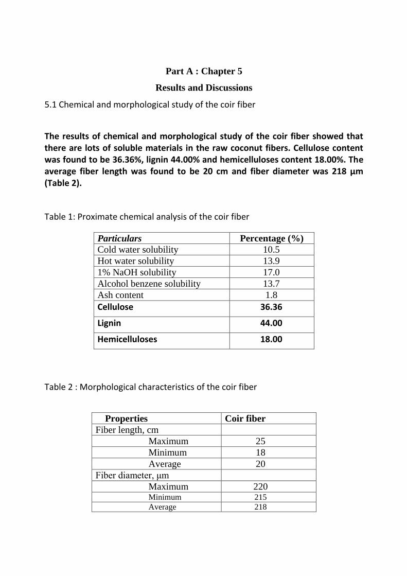
5.1 Chemical and morphological study of the coir fiber
The results of chemical and morphological study of the coir fiber showed that there are lots of soluble materials in the raw coconut fibers. Cellulose content was found to be 36.36%, lignin 44.00% and hemicelluloses content 18.00%. The average fiber length was found to be 20 cm and fiber diameter was 218 µm (Table 2).
Table 1: Proximate chemical analysis of the coir fiber
Particulars Percentage (%)
Cold water solubility 10.5
Hot water solubility 13.9
1% NaOH solubility 17.0
Alcohol benzene solubility 13.7
Ash content 1.8
Cellulose 36.36
Lignin 44.00
Hemicelluloses 18.00
Table 2 : Morphological characteristics of the coir fiber
Properties Coir fiber
Fiber length, cm
Maximum 25
Minimum 18
Average 20
Fiber diameter, μm
Maximum 220 Minimum 215
Average 218

5.2 Study on surface treatments of fiber
The surface treatment of the coir fiber was carried out by hydrochloric acid, acetic acid, ethanol-benzene and sodium hydroxide at different concentrations under controlled condition. Table 3 shows the chemical constituents of both untreated and treated coir fiber. It has been observed from the Table that the lignin content was recorded 40% for hydrochloric acid treated fiber, while 39%, 35% and 24% recorded for acetic acid, ethanol-benzene and sodium hydroxide treated fiber respectively. In case of untreated fiber lignin content was recorded 44%. The higher lignin content makes the fiber more rigid and stiff compare to other natural fiber. Lignin provides plant tissue and individual fibers with compressive strength and protects the carbohydrates from chemical and physical damage. But after treatment removal of lignin decreases rigidity and stiffens of the fiber and enhanced the surface roughnesses which will ultimately helps in compatibility of fiber to bond with the polyethylene matrix for making composites.
Table 3: Chemical constituents of untreated and treated coir fiber
Particulars
Untreated
(%)
HCl treated
(%)
CH3COOH treated
(%)
Alcohol-benzene
treated (%)
NaOH treated
(%)
Ash 2.00 5.00 4.00 3.00 4.00
Cellulose 36.36 36.53 37.21 37.50 38.53
Lignin 44.00 40.00 39.00 35.00 24.00
Hemicelluloses 18.00 8.00 15.00 13.00 6.00
Hot Water Soluble
13.9 2.35 5.84 6.78 5.4
Pentosan Content
8.74 3.82 7.65 6.56 7.25
Alcohol-benzene solubles (wax,
13.7 6.75 5.89 16.56 12.48

Table 3 represents the different constituents of coir fiber including cellulose,
lignin, hemicelluloses, pentsan content of untreated and treated fiber. In case of
untreated fiber hemicelluloses content was recorded 18%, while after chemical
treatment it was reduced and recorded 8% after hydrochloric acid treatment, 15%
after acetic acid treatment, 13% after ethanol-benzene treatment and 6% after
sodium hydroxide treatment respectively. Among all the treatments, alkali
treatments remove higher percentage of hemicellulose from the fiber and as a
result showed a greater exposure of cellulose has taken place and thereby increase
in thermal stability. Hemicellulose is strongly bound to cellulose fibrils most
probably by hydrogen bonds. Hemicellulosic polymers are branched, fully
amorphous and have a significantly lower molecular weight than cellulose.
Because of its open structure containing many hydroxyl and acetyl groups,
hemicelluloses is partly soluble in water and hygroscopic.
So also, cellulose content recorded 36.36% for untreated fiber, while 36.53%,
37.21%, 37.50% and 38.53% for hydrochloric acid, acetic acid, ethanol-benzene,
and sodium hydroxide treated respectively. Presence of hydroxyl groups of the
cellulose in coir is responsible for its inherent hydrophilic nature. Treatments were
done to reduce the number of free hydroxyl groups of cellulose. This would result
in the reduction of the polarity of cellulose molecules and in the improvement of
its compatibility with the thermosetting matrix used in composites. Among all the
treatment used for modification of surface properties of coir fiber, the alkali
treatment showed better result in terms of quality and strength. Chemical treatment
decreases the amorphous region of the fibers resulting in the increase in crystalline
portion. Because of higher crystallinity of cellulose improves the bonding property
as well as ultimate tensile strength.
After the chemical treatment, removal of impurities like wax, tannin and other
non-cellulosic polysaccharides improved the fiber properties suitable for making
composite have been observed. The fibrils get separated from each other because
of lignin, the cementing component had been removed by the action of chemical
treatment, leading to an increase of the surface area and potentially improving the
fiber-matrix adhesion in composite.
resin etc)

FIG. 1. FT-IR spectra of untreated and treated coir fiber .
The FTIR spectra (Figure1) of treated and untreated coir fiber showed a broad and
intense band centring at ~3400 cm-1
due to the hydrogen bonded O-H stretching
vibration from the cellulose. The IR band at ~2925 cm-1
for untreated fiber is
assigning to -CH2 antisymmetric stretching. This band at ~2925 cm-1
shifted to
~2900 cm-1
for treated coir fiber with decrease in intensity, which concluded that
carbon atoms attached to carbon or hydrogen (-C-C- or –C-H) decrease. The
untreated coir fiber also showed an absorption band at ~1735 cm-1
due to -C=O
stretching of the carbonyl and acetyl groups in the 4-O-methyl-glucuronoacetyl
xylan component of hemicelluloses in coir fiber. The band is disappeared for the
treated fiber indicating removal of hemicelluloses component. The treated and
untreated fiber also showed an absorption band at ~1607 cm-1
due to adsorbed
water molecule. The intensity of this band increased upon treatment under
controlled condition. The band at ~1510 cm-1
for untreated fiber due to presence of
aromatic rings of lignin which shifted to ~1498 cm-1
with decrease in intensity for
treated fiber indicating partial removal of the lignin. A band at ~1250 cm-1
was
observed for untreated coir fiber which may be attributed to -C-O-C- bond in the
cellulosic chain. This band shifted to ~1258 cm-1
for treated fiber indicating the
change in the bonding environment due to dissolution of hemicelluloses during
treatment.
FIG. 2. TGA of
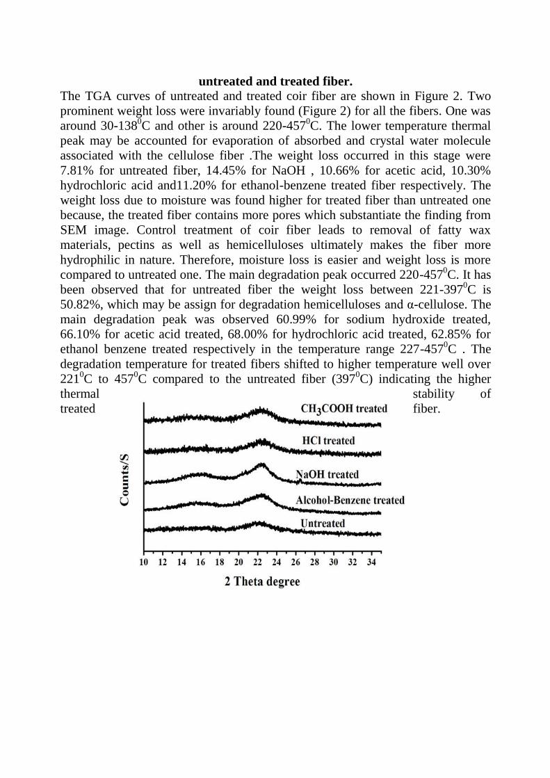
untreated and treated fiber.
The TGA curves of untreated and treated coir fiber are shown in Figure 2. Two
prominent weight loss were invariably found (Figure 2) for all the fibers. One was
around 30-1380C and other is around 220-457
0C. The lower temperature thermal
peak may be accounted for evaporation of absorbed and crystal water molecule
associated with the cellulose fiber .The weight loss occurred in this stage were
7.81% for untreated fiber, 14.45% for NaOH , 10.66% for acetic acid, 10.30%
hydrochloric acid and11.20% for ethanol-benzene treated fiber respectively. The
weight loss due to moisture was found higher for treated fiber than untreated one
because, the treated fiber contains more pores which substantiate the finding from
SEM image. Control treatment of coir fiber leads to removal of fatty wax
materials, pectins as well as hemicelluloses ultimately makes the fiber more
hydrophilic in nature. Therefore, moisture loss is easier and weight loss is more
compared to untreated one. The main degradation peak occurred 220-4570C. It has
been observed that for untreated fiber the weight loss between 221-3970C is
50.82%, which may be assign for degradation hemicelluloses and α-cellulose. The
main degradation peak was observed 60.99% for sodium hydroxide treated,
66.10% for acetic acid treated, 68.00% for hydrochloric acid treated, 62.85% for
ethanol benzene treated respectively in the temperature range 227-4570C . The
degradation temperature for treated fibers shifted to higher temperature well over
2210C to 457
0C compared to the untreated fiber (397
0C) indicating the higher
thermal stability of
treated fiber.

FIG. 3. X-ray diffraction spectra of untreated and treated coir fiber.
XRD studies of different treated and untreated fibers were carried out to
investigate the crystalline behaviour of coir fiber (Figure 3). XRD analysis showed
two main peaks representing the planes 101 and 002 at 2θ around 160 and 22.4
0
respectively, characteristic of cellulose crystalline phase of the fiber. Crystallinity
index (CI) was calculated according to equation 1, it was found 27.16 % in case of
untreated fiber whereas, it was recorded 30.07 %, 32.5 %, 28.71 % and 33.87 %,
for acetic acid, hydrochloric acid, ethanol- benzene, sodium hydroxide treatment
respectively. The higher CI of treated fiber than untreated one due to removal of
residual lignin increased the exposure of the cellulose, resulting in the crystalline
index. X-ray graph shows that the chemically treated fiber peaks were more
intense than untreated fibers i.e. treatments were able to remove part of the
amorphous material covering the fiber.
5.3 Scanning Electron Microscopic Study of the Untreated and Treated Coir
Fiber
Experiments were carried out to study the structure of both treated and untreated
coir fiber with the help of Scanning Electron Microscope (SEM). Untreated coir
fibers were properly washed with fresh water dried in an oven and made bundle
free with the help of carding machine. However the treated fibers were also made
bundle free with the help of carding machine and then washed properly with fresh
water and dried in sunlight.
(a) (b) (c)
FIG. 4. Scanning electron microphotograph of untreated coir fiber at (a) magnification x 330, (b) magnification x1000 (c) magnification x 5500)
SEM pictures of untreated coir-fiber surfaces at increasing magnifications are
shown in Figure 4. From all three pictures, it can be observed that the unit cells run
longitudinally with more or less parallel orientations. Irregular pores and
longitudinal cracks are visible on the surface of the fiber. The intercellular gaps, in
the form of shallow longitudinal cavities, can be clearly marked as the unit cells
are partially exposed. The intercellular space is filled up by the binder lignin and
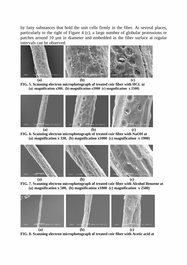
by fatty substances that hold the unit cells firmly in the fiber. At several places,
particularly to the right of Figure 4 (c), a large number of globular protrusions or
patches around 10 µm in diameter and embedded in the fiber surface at regular
intervals can be observed.
(a) (b) (c)
FIG. 5. Scanning electron microphotograph of treated coir fiber with HCL at (a) magnification x300, (b) magnification x1000 (c) magnification x 2500)
(a) (b) (c)
FIG. 6. Scanning electron microphotograph of treated coir fiber with NaOH at
(a) magnification x 330, (b) magnification x1000 (c) magnification x 1900)
(a) (b) (c)
FIG. 7. Scanning electron microphotograph of treated coir fiber with Alcohol Benzene at
(a) magnification x 500, (b) magnification x1000 (c) magnification x 2500)
(a) (b) (c)
FIG. 8. Scanning electron microphotograph of treated coir fiber with Acetic acid at

(a) magnification x 500, (b) magnification x 1500 (c) magnification x 4300)
SEM pictures of the HCL treated coir fiber at increasing magnifications are shown
in Figure 5 (a–c). In these pictures are apparent a larger number of surface cracks,
or pit formations, compared to Figure 6 (b & c). These might occur because of the
partial removal of wax and fatty substances during the treatment with HCL solvent
mixture. Very interestingly, the parallel unit cells look partially split due to the
removal of fatty materials. Micrographs with increasing magnifications of the
dilute NaOH treated, alcohol benzene, acetic acid treated fibers are shown in
Figure 6 (a-c), 7 (a-c) and 8 (a-c) respectively. The pictures show a large number
of regularly placed holes or pits on the surfaces. These may be due to the removal
of fatty-deposit tyloses on the surface. Given the large number of these pits, it can
be considered that a large number of the tyloses, globular fatty deposits, were
lying hidden inside the surfaces of the untreated fiber. These were therefore not
revealed in the untreated fiber, which were partially revealed in the alcohol
benzene and acetic acid treated fibers and largely revealed in the fiber treated with
dilute NaOH and HCL. Alkali treatment at lower concentration, thickening of the
cell walls does not occur, and hence the shrinkage of the unit cells does not take
place. This can be verified by comparing the nature of the unit cells and the
intercellular gaps for untreated and dilute alkali–treated fibers. Barring the
formation of pits, the overall surface morphology among the all four treated fiber
does not change much.
5.4 Board making from mixture of coir fiber and waste polyethylene
A series of experiments were conducted in the laboratory for making composite
board from chemically treated coir fiber and waste polyethylene cuttings. Waste
polyethylene bags (PE) of lower density were considered for the present
investigation. The waste bags were first screened and after removal of dust and
foreign particles, these were cut in a chopping machine into the size of 1-1.5 cm
length. The cut pieces obtained from the chopper were mixed with coir fiber for
making the boards. The polywaste cuttings were mixed with coir fibers in such a
way that the cut pieces were uniformly distributed all around the fiber mass. The
mixtures were then taken in a wooden mould of size 30 X 30 cm and then put
under hot press at 80±5°C for 20 min and at 130±5 kg/cm2 pressure. A releasing
agent was spreaded in the both side of the fiber mass before hot pressing. After
that, the pressure was released from the hot press and the boards were kept outside
in open air for some time for cooling and removed from the mould (the detailed
process is presented in Fig 5). A number of experiments were conducted in the
laboratory to optimize the ratio of coir fiber and PE, temperature, pressure, time
requirement to get uniform quality boards. The physical strength properties of the
boards made from treated coir fiber and PE waste cuttings were tested and the
results are presented in Table 4.
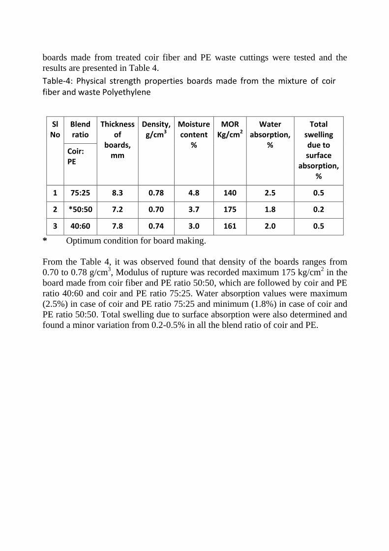
Table-4: Physical strength properties boards made from the mixture of coir fiber and waste Polyethylene
Sl No
Blend ratio
Thickness of
boards, mm
Density, g/cm3
Moisture content
%
MOR Kg/cm2
Water absorption,
%
Total swelling due to surface
absorption, %
Coir: PE
1 75:25 8.3 0.78 4.8 140 2.5 0.5
2 *50:50 7.2 0.70 3.7 175 1.8 0.2
3 40:60 7.8 0.74 3.0 161 2.0 0.5
* Optimum condition for board making.
From the Table 4, it was observed found that density of the boards ranges from
0.70 to 0.78 g/cm3, Modulus of rupture was recorded maximum 175 kg/cm
2 in the
board made from coir fiber and PE ratio 50:50, which are followed by coir and PE
ratio 40:60 and coir and PE ratio 75:25. Water absorption values were maximum
(2.5%) in case of coir and PE ratio 75:25 and minimum (1.8%) in case of coir and
PE ratio 50:50. Total swelling due to surface absorption were also determined and
found a minor variation from 0.2-0.5% in all the blend ratio of coir and PE.

Processed coir fiber Polyethylene (PE) waste
Mixer
of PE waste Placed in mould
Pressed under hydraulic Hot Press Coir-Polyethylene composite Board
FIG.5 Board making process : Composite board making from the mixture of coir fiber and low density polyethylene (LDPE)

A series of experiments were conducted in the laboratory for making composite board
with chemically treated coir fiber using low density polyethylene as binding material.
Low density polyethylene (powder) and coir fibers were procured from the local
market of Jorhat. Cleaned fibers were cut into 2-3 mm size with the help of fiber
cutting machine. The cut fibers were screened to remove the dust and over sized
particles.
For making the composite, LDPE powder were mixed with coir fibers in such a
way that it is uniformly distributed all around the fiber mass. The mixtures were
then taken in a wooden mould of the size 30 X 30 cm and later put under a
hydraulic hot press at 100±5°C for 20 min and at 130±5 kg/cm2 pressure. A
releasing agent was spreaded over both the side of the fiber mass before hot
pressing. After hot pressing, the pressure of the hydraulic hot press
was released and the boards were removed from the mould and kept outside in
open air for conditioning. A number of experiments were conducted in the
laboratory to optimize the parameters such as ratio of coir fiber and LDPE,
temperature, pressure, time requirement to get uniform quality boards. The
physical strength properties of the boards made from chemically treated coir fiber
and LDPE were tested and the results are presented in Table 3.
Table. 5: Physical strength properties composite board from treated and
untreated coir fiber and LDPE
Sample Width
(mm)
Thicknes
s
(mm)
Density
Kg/cm3
Elongati
on at
max.
load
(mm)
UTS
N/mm2
Strain
(%)
Untreated fiber
+LDPE 50 24 0.931 7.94 6.399 4.961
NaOH treated
fiber +LDPE 51 24 0.833 11.74 7.275 7.336
HCl treated
fiber +LDPE 48 24 0.945 6.12 7.223 3.826
CH3COOH
treated fiber +
LDPE
51 24 0.900 10.80 6.933 6.154
Alcohol-
benzene treated
fiber +LDPE
51 24 0.956 10.45 7.150 6.350

From the Table 5, it was found that density of the boards varies from 0.833 to
0.956 g/cm3. It has also been observed that ultimate tensile strength (UTS) of the
boards found improving after the chemical modification by different chemicals. It
was found in the study that maximum UTS (7.275 N/mm2) in case of composite
board made from the mixture of NaOH treated coir fiber and LDPE followed by HCl
treated fiber (7.223 N/mm2), Alcohol benzene treated fiber (7.150 N/mm
2) and
Acetic acid treated fiber (6.933 N/mm2). Strain (%) was minimum in case of
boards prepared from HCl treated fiber and LDPE (3.826 %) followed by acetic
acid treated fiber (6.154%), alcohol benzene treated fiber (6.350%) and NaOH
treated fiber (7.336%). Composite board made from HCl treated fiber showed less
strain (%) to that of untreated one (4.961%).
FIG 6 Tensile strength properties of treated and untreated coir composite
board
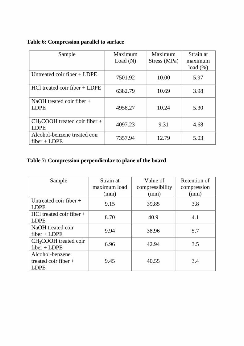
Table 6: Compression parallel to surface
Sample Maximum
Load (N)
Maximum
Stress (MPa)
Strain at
maximum
load (%)
Untreated coir fiber + LDPE
7501.92 10.00 5.97
HCl treated coir fiber + LDPE
6382.79 10.69 3.98
NaOH treated coir fiber +
LDPE
4958.27 10.24 5.30
CH3COOH treated coir fiber +
LDPE 4097.23 9.31 4.68
Alcohol-benzene treated coir
fiber + LDPE 7357.94 12.79 5.03
Table 7: Compression perpendicular to plane of the board
Sample Strain at
maximum load
(mm)
Value of
compressibility
(mm)
Retention of
compression
(mm)
Untreated coir fiber +
LDPE 9.15 39.85 3.8
HCl treated coir fiber +
LDPE 8.70 40.9 4.1
NaOH treated coir
fiber + LDPE 9.94 38.96 5.7
CH3COOH treated coir
fiber + LDPE 6.96 42.94 3.5
Alcohol-benzene
treated coir fiber +
LDPE
9.45 40.55 3.4

FIG 7 : Compression test properties of untreated and treated coir fiber with
LDPE
Compression test is the opposite of the tension with respect to the direction of
loading. In compression test the board sample is squeezed while the load
and the displacement are recorded. The highest stress value (12.79 MPa) was
recorded in case of board prepared from alcohol benzene treated fiber.
Composite board prepared from acetic acid treated fiber showed less
compressive strength to that of untreated one which may be due to the internal
deformation occurs during board making. The results for all other boards made
from treated fiber sample are almost in the similar range.
The lignin rich coconut fiber is weak compared to the cellulose rich fibers such as
sisal, jute, pineapple etc. Certain unique properties make them attractive for
using in reinforcement. Coconut fiber possesses high failure strain of 15-40% and
contains a thin continuous surface layer of an aliphatic compound, referred as
waxy layer. The waxy layer consists of long chain fatty acids and their condensation
products. The layer was found incompatible with polymer resin and removal of the
layer was necessary to have good interfacial bonding in such polar-matrix
composites. Therefore, various chemical treatments are employed to improve the
interfacial bonding between fiber and polymer matrix. Moreover, long chain
aliphatic molecules and compounds have been used as adhesion promoters in
fiber reinforced non-polar thermoplastic composites. High failure strain of the
fiber which provides a better strain compatibility between the fiber and the
matrix could also be advantageous in coir fiber LDPE composites.
Therefore, considering the environmental problems, it may be suggested that the
use of waste polyethylene material as binding material for manufacturing building
construction materials like particle/composite board may play an important role in
the development of new building and construction material substitute to wood.
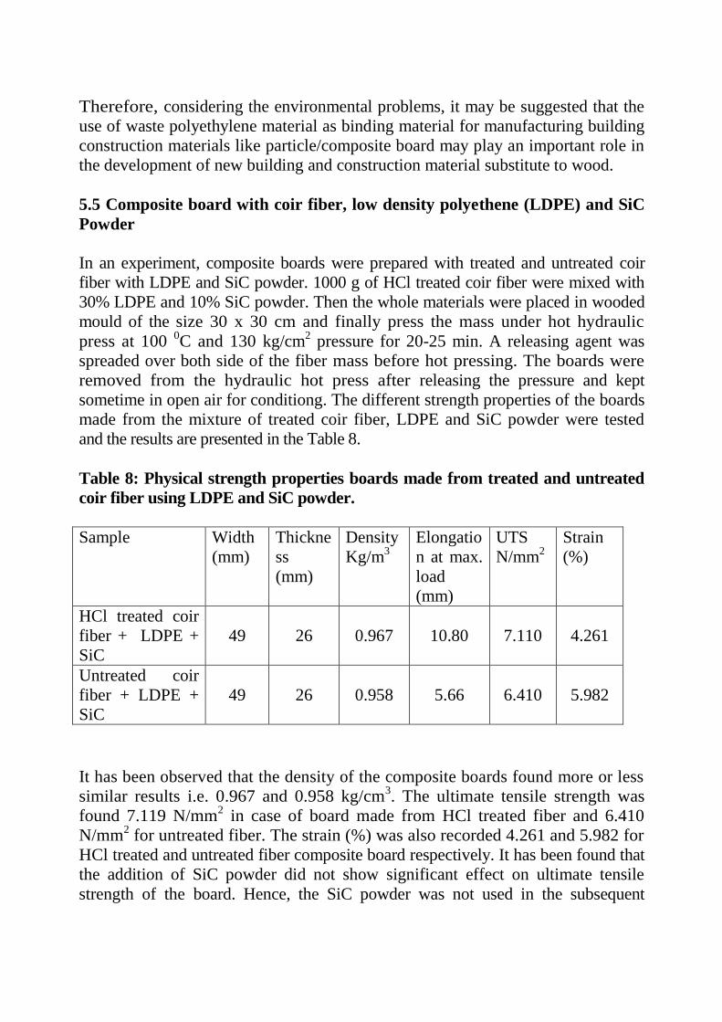
5.5 Composite board with coir fiber, low density polyethene (LDPE) and SiC
Powder
In an experiment, composite boards were prepared with treated and untreated coir
fiber with LDPE and SiC powder. 1000 g of HCl treated coir fiber were mixed with
30% LDPE and 10% SiC powder. Then the whole materials were placed in wooded
mould of the size 30 x 30 cm and finally press the mass under hot hydraulic
press at 100 0C and 130 kg/cm
2 pressure for 20-25 min. A releasing agent was
spreaded over both side of the fiber mass before hot pressing. The boards were
removed from the hydraulic hot press after releasing the pressure and kept
sometime in open air for conditiong. The different strength properties of the boards
made from the mixture of treated coir fiber, LDPE and SiC powder were tested
and the results are presented in the Table 8.
Table 8: Physical strength properties boards made from treated and untreated
coir fiber using LDPE and SiC powder.
Sample Width
(mm)
Thickne
ss
(mm)
Density
Kg/m3
Elongatio
n at max.
load
(mm)
UTS
N/mm2
Strain
(%)
HCl treated coir
fiber + LDPE +
SiC
49 26 0.967 10.80 7.110 4.261
Untreated coir
fiber + LDPE +
SiC
49 26 0.958 5.66 6.410 5.982
It has been observed that the density of the composite boards found more or less
similar results i.e. 0.967 and 0.958 kg/cm3. The ultimate tensile strength was
found 7.119 N/mm2 in case of board made from HCl treated fiber and 6.410
N/mm2 for untreated fiber. The strain (%) was also recorded 4.261 and 5.982 for
HCl treated and untreated fiber composite board respectively. It has been found that
the addition of SiC powder did not show significant effect on ultimate tensile
strength of the board. Hence, the SiC powder was not used in the subsequent

experiments.
The board samples made from the treated and untreated coir using LDPE
mixture shows satisfactory physical strength properties. The use of LDPE powder
for making coir composite board has certain advantages which not only helps in
enhancing physical strength of the boards, but also reduces the water absorption.
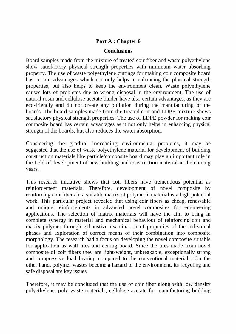
Part A : Chapter 6
Conclusions
Board samples made from the mixture of treated coir fiber and waste polyethylene
show satisfactory physical strength properties with minimum water absorbing
property. The use of waste polyethylene cuttings for making coir composite board
has certain advantages which not only helps in enhancing the physical strength
properties, but also helps to keep the environment clean. Waste polyethylene
causes lots of problems due to wrong disposal in the environment. The use of
natural rosin and cellulose acetate binder have also certain advantages, as they are
eco-friendly and do not create any pollution during the manufacturing of the
boards. The board samples made from the treated coir and LDPE mixture shows
satisfactory physical strength properties. The use of LDPE powder for making coir
composite board has certain advantages as it not only helps in enhancing physical
strength of the boards, but also reduces the water absorption.
Considering the gradual increasing environmental problems, it may be
suggested that the use of waste polyethylene material for development of building
construction materials like particle/composite board may play an important role in
the field of development of new building and construction material in the coming
years.
This research initiative shows that coir fibers have tremendous potential as
reinforcement materials. Therefore, development of novel composite by
reinforcing coir fibers in a suitable matrix of polymeric material is a high potential
work. This particular project revealed that using coir fibers as cheap, renewable
and unique reinforcements in advanced novel composites for engineering
applications. The selection of matrix materials will have the aim to bring in
complete synergy in material and mechanical behaviour of reinforcing coir and
matrix polymer through exhaustive examination of properties of the individual
phases and exploration of correct means of their combination into composite
morphology. The research had a focus on developing the novel composite suitable
for application as wall tiles and ceiling board. Since the tiles made from novel
composite of coir fibers they are light-weight, unbreakable, exceptionally strong
and compressive load bearing compared to the conventional materials. On the
other hand, polymer wastes become a hazard to the environment, its recycling and
safe disposal are key issues.
Therefore, it may be concluded that the use of coir fiber along with low density
polyethylene, poly waste materials, cellulose acetate for manufacturing building
construction materials like particle and composite board may play an important
role in development of new building and construction material in the coming
years.
Research papers*
1. “Development and Characterization of new composite materials based on
polymeric waste and modified agro-fibre” by Himadri Das, Dipanka Dutta,
Pallav Saikia, Dipul Kalita and Tridip Goswami, Proceedings of the Second
International Conferences on Advances in Materials Processing and
Characterization (AMPC 2013) Vol 1, 120-127.
2. “Effect of chemical treatment of coir fibre on quality of coir-polyethylene
waste composite board” Pallav Saikia, Dipul Kalita, Dipanka Dutta, J J
Bora and Tridip Goswami, 99th Indian science Congress, 2012 held at KIIT
University, Bhubaneswar from 3-7 January, 2012. (Abstract No MSP10)
3. “Modification of properties of coir fibre by chemical treatments for making
composite material” by Himadri Das, P K Das, Dipanka Dutta, Dipul Kalita
and Tridip Goswami, 57th
Technical Session of Assam Science Society, held
at Gauhati University, Guwahati on 16 March, 2012. (Abstract No BT-02)
*the copies of the papers are attached in the annexure
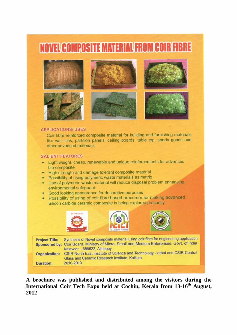
A brochure was published and distributed among the visitors during the
International Coir Tech Expo held at Cochin, Kerala from 13-16th
August,
2012

Part B: Work Done At CSIR-CGCRI,
Kolkata, West Bengal

Part B: Chapter 1
Introduction
For the last two decades there has been a tremendous initiative by the researcher
community all over the globe to synthesize novel ceramic composite materials by
replication of naturally occurring plant bio-structures. Ceramics with cellular
anatomical features typical of wood structures are possible to be produced that
exhibit unique properties ~ light weightiness, high stiffness, anisotropy, etc. Also,
the processing has certain advantages. Ceramics can be made from bio-precursors
that are less expensive than the raw powders (mostly inorganic powders); green
shape making which is a very critical step in conventional processing of ceramics
when they are prepared from powders (conventional powder route), can be
possible to be totally avoided when ceramics are made from bio-precursors
(biomimetic processing or bio-template based processing route), as any desired
shape can be easily given to woody materials. CSIR-Central Glass and Ceramic
Research Institute, has been pursuing research on this novel processing of SiC
based non-oxide ceramics since 2000.
There has been a strong possibility to synthesize novel SiC based ceramic
composite materials from coir fibres ~ an agricultural waste materials with
immense economic potential in a country like India. If this possibility can be
realized it may add more value to coir fibres. One of purposes of the project was to
examine the possibility of synthesizing SiC based ceramics using coir fibres. This
work has been done at CSIR- Central Glass and Ceramic Research Institute,
Kolkata. The other purpose of the project was to synthesize novel composite
boards using coir fibres in combination with poly waste materials. This work has
been done at CSIR-North East Institute of Science and Technology, Jorhat, Assam.
This part of the project report (Part B) is related to the work done at CSIR-CGCRI
on synthesis of SiC ceramics from coir fibres.
The report contains a brief contemporary background of research on innovative
synthesis of ceramic materials using plant bio-structures as precursors, in the form
of a literature review, in chapter 2. Chapter 3 describes with the objectives of the
project and experimental outlines briefly highlighting different stages of the
processing and characterization of materials ~ precursors, intermediate carbon
templates and end ceramics. Chapter 4 contains the description of experimental
work done on processing of bio-precursors and results of characterization of bio-
precursors, chapter 5 contains the description of experimental work done on
intermediate carbon template making and results of characterization of carbon
templates and chapter 6 gives an account of the experimental work done on
synthesis of SiC based ceramic composites and includes the results of
characterization of SiC ceramic composites. This chapter also contains the results
of the test on examination of applicability of the SiC ceramics as structural
materials. Finally technical conclusions are given in chapter 7 with indication of
future possibilities of research and an account of research publications and other
similar outputs is also included in this chapter.

Part B: Chapter 2
Review of literature
Synthesis of ceramic materials from naturally grown plant structures has received increasing interests in the past years. Plants like woods, palms or grasses are characterized by a porous microstructure and possess natural composite morphology with high mechanical strength, low density, high stiffness, elasticity and damage tolerance. Recently it has been demonstrated, that by using various plant parts, plant structures or plant derived materials as starting precursors, ceramics of different microstructures, morphologies and compositions can be produced, e.g. fibers, felts, bulk monoliths or composites, porous or dense
materials.1,2 Attempt was made to produce boron carbide (B4C)-fibers by infiltrating cellulose fibers with boric acid followed by high temperature
annealing.3
Alumina (Al2O3) and titania (TiO2) fibers were produced by infiltrating sisal, jute and hump with aluminium choloride (AlCl3) and titanium chloride
(TiCl4) and subsequent heating in air.4,5 Fibrous cotton was converted into SiC
fiber by uniformly coating it with Si3N4 and heating in argon atmosphere.6 Recent research also suggested that silicon carbide (SiC) powder or whiskers might be obtained by thermal treatment of rice husk (RH) or coconut shell, a natural
agricultural waste material.7-11 A porous titania (TiO2) ceramic with a wood-like structure was produced by infiltrating carbonized wood with titanium
tetraisopropoxide and subsequent firing to 1400oC in air.12 Similarly alumina sol infiltration into wood char followed by heating in air produced a porous
biomorphic Al2O3 ceramics13,14
, while nitridation of SiO2- or Al2O3-sol infiltrated pyrolyzed wood resulted in synthesis of Si3N4 or AlON ceramics having
microcellular structure.14 Silicon nitride ceramics were also produced from woods
and sea sponges following sol infiltration and reduction-nitridation processes.15,16
Silicon carbide (SiC) is an important engineering ceramic material with high strength that can be retained up to high temperatures, good oxidation, corrosion, erosion and thermal shock resistances, high hardness and high thermal conductivity. Single phase porous SiC ceramics were prepared by infiltration silica
sol into pyrolyzed woods followed by carbothermal reduction reaction.17-19
Dense SiC based ceramic composite materials with reinforcement of suitable phases were developed via transformation of hierarchically designed composite morphology of plants structures to ceramic structures. SiC bases ceramic composites were
manufactured using woods of various kinds20-26, charcoal21 or saw dust23 as starting precursors. The products were mainly a two-phase Si-SiC composite having

anisotropic microstructures isomorphous to the initial wood cell morphology. It has
also been possible to synthesize biomorphic Si-MoSi2-SiC ternary composite
materials using wood as the starting materials.27
The precursors of naturally grown plants have certain limitations. The parts of
plants (for example, woods) exhibit variation of properties even in a particular
species and such variation is dependent on the origin, location, age, etc. of the
natural plant. These variations are reflected in the changing microstructures of the
SiC ceramics synthesized from plant precursors causing fluctuation of properties.
Efforts were therefore made to produce SiC ceramic composites using processed
bio-structures, for example, paper28,29
, paper derived composites30
, cotton linter31
,
medium density fibreboard (MDF)32,33, wood powder-resin composite,34, bamboo
pulp fibreboard,35 etc.
There has been a strong possibility of utilization of coir fibres for synthesis of SiC
based ceramic composites. Coir is a natural fibre obtained from coconut husk by
the process of retting or mechanical defibring. They are harsh and tough fibres36
and are mostly used for producing doormats, mating, mattress, etc. Utilizing coir
fibres building and furnishing materials are made which can serve as substitutes of woods. Efforts concerning making of boards for partition panels, ceiling boards,
table tops, etc., using coir fibres are increasing becoming popular.37, 38 However, a
scan of the literature pertaining to plant bio-structure based synthesis of SiC ceramics, does not indicate a single study conducted till recently that tried to exploit the immense possibilities of coconut coir to be used for making the ceramics.
It becomes, thus, necessary to undertake a systematic scientific investigation with
intent of exploring the possibilities of coconut coir to become a precursor to SiC
ceramic composites and it acts as the motivation of undertaking the current project.
Part-by-part study of the process steps of conversion of coirs to ceramics including
examination of physical changes and chemical reactions of the conversions
processes, characterization of the process steps and materials (raw materials,
intermediates and products) of the conversion-chain, evaluation of the properties of
the novel SiC ceramic products, indication of their application possibilities, etc. are
the areas where no studies are almost conducted globally till now. Coir being a
agricultural waste material with tremendous economic potential in a country like
India, the studies undertaken in the current project are therefore highly relevant to
the global context as well as in the context of the economic need of our country.

References
1. P. Greil, „Lignocellulosics, J. Euro. Ceram. Soc., 18[14], 1961-1973 (1998)
2. H. Sieber, C. Hoffmann, A. Kaindl, P. Greil, “Biomorphic cellular ceramics”,
Adv. Eng. Mater., 2 [3] 105-109 (2000)
3. Y.Bohne, H.P.Martin and E.Muller, “ Production of boron carbide fibers
using boric acid and cellulose fibers” in „Proc. of the Eleventh International
Conference on Composite Materials, Gold Coast, Australia, July,1997, Vol.
IV (Ed. M.L.Scott), Woodhead Publisher Ltd., 1997,pp. 643-651, Cambridge,
England
4. M.Patel and B.K.Padhi, “Production of alumina fiber through jute fiber
substrate,” J.Mat.Sci., 25, 1335-1343, 1990
5. M.Patel and B.K.Padhi, “Titana fibers through jute fiber substrate”,
J.Mat.Sci.Lett, 12, 1234-1235, 1993
6. R.V.Krikrishnarao and Y.R.Mahajan, “ Preparation of silicon carbide fiber
from cotton fiber and silicon nitride”, J.Mat.Sci.Lett, 15[1-6],l 232-235, 1996
7. J.E.Lee and I.B.Cutler, “Formation of silicon carbide from rice hulls”,
Am.Ceram.Soc.Bull., 54, 195-198, 1975
8. N.K.Sharma et al., “Formation and structure of silicon carbide whiskers
from rice hulls”, J.Am.Ceram.Soc., 67, 715-720, 1984
9. M. Patel et al., “Effect of thermal and chemical treatments on the carbon and
silica contents in rice husk”, J.Mat.Sci., 22, 2457-2464, 1987
10. M.Patel and A.Karera, “SiC whiskers from rice husks: role of catalysts”,
J.Mat.Sci.Lett, 8, 955-956, 1989
11. A. Selvam et al., “Synthesis and characterization of SiC whiskers from
coconut shell”, J.Mat.Sci.Lett, 17, 57-60, 1998
12. T.Ota, “Porous titania ceramic prepared by mimicking silicified wood”,
J.Am.Ceram.Soc., 83, 1521-23, 2000
13. J. Cao, C. R. Rambo, H. Sieber, “Preparation of porous alumina ceramics by
biotemplating of wood”, J. Por. Mat. 11 (2004) 163-172.
14. C.E.Byrne and D.E.Nagle, “Cellulose derived composites- a new method for
materials processing,” Mat.Res.Innovat., 1, 137-145,1997.
15. M. Luo, J. Q. Gao, J. F. Yang, J. Z. Fang, W. Wang, “Biomorphic silicon
nitride ceramics with fibrous morphology prepared by sol infiltration and
reduction-nitridation”, J. Am. Ceram. Soc., 90 (12) (2007) 4036–4039.
16. C. R. Rambo, H. Sieber, L. A. Genova, Synthesis of porous biomorphic /
Si3N4 composite from sea sponge, J. Por. Mat. 15 (2008) 419-425.
17. T. Ota, M. Takahashi, T. Hibi, M. Ozawa, S. Suzuki, Y. Hikichi, H. Suzuki,
“Biomimetic process for producing SiC wood”, J. Am. Ceram. Soc.
78 (12) (1995) 3409–3411.
18. J. Qian, J. Wang, Z. Jin, Preparation of biomorphic SiC ceramic by
carbothermal reduction of oak wood charcoal, Mat. Sci. Eng. A 371 (1-
2) (2004) 229-235.
19. A. Herzog, R. Klingner, U. Vogt, T.Graule, Wood derived porous SiC
ceramics by sol infiltration and carbothermal reduction, J. Am. Ceram.
Soc. 87 (5) (2004) 784-793.
20. P. Greil, T. Lifka and A. Kaindl, “Biomorphic Cellular silicon carbide
ceramics from wood”, J. Euro. Ceram. Soc., 18[14], 1961-1973 (1998)
21. D. W. Shin, S. S. Park, Y. H. Choa, K. Niihara, “Silicon/silicon carbide
composites fabricated by infiltration of a silicon melt into charcoal”, J. Am.
Ceram. Soc, 82(11) (1999) 3251-3253.

22. J. Martínez-Fernández, F.M. Valera-Feria and M. Singh, “High Temperature Compressive Mechanical Behavior of Biomorphic Silicon Carbide
Ceramics,” Scripta Materialica, 43 [9], 813-818 (2000)
23. M. Singh, “Environment conscious ceramics”, Ceram. Eng. Sci. Proc.,
21[4], 39-44 (2000)
24. M. Singh and J.A. Salem, “Mechanical properties and microstructure of
biomorphic silicon carbide ceramics fabricated from wood
precursors”, J. Eur. Ceram. Soc. 22 (2002) 2709- 2717.
25. A. Hofenauer, O. Treusch, F. Tröger, G. Wegener, J. Fromm, M. Gahr, J.
Schmidt, W. Krenkel, “Dense reaction infiltrated silicon/silicon
carbide ceramics derived from wood based composites”, Adv. Eng. Mater.
5(11) 794-799 (2003).
26. O. P. Chakrabarti, H. S. Maiti, R. Majumdar, Biomimetic synthesis of
cellular SiC based ceramics from plant precursor, Bull. Mater. Sci. 27, 467-
470(2004).
27. O. P. Chakrabarti, L. Weisensel and H. Sieber, Reactive melt infiltration
processing of biomorphic Si-Mo-C ceramics from wood, J. Am. Ceram. Soc.
88[7] 1792-1798,(2005).
28. Y. Ohza, “Preparation of high temperature filter by pressure pulsed chemical
vapor infiltration of SiC into carbonized paper fiber preform”,J. Mater. Sci.,
33, 3259, 1998
29. G. Yang, Y. Liu, G. Qiao, J. Yang, H. Wang, “Preparation and R curve
properties of laminated Si/SiC ceramics from paper”, Mat. Sci. Eng. A 492,
327-332, (2008).
30. H.Seiber et al., “Ceramic light-weight structure from paper derived
composite”, Ceramic Transaction, 108,571, 2001
31. T. Xue, Z. Jin, W. Wang, “Preparation and characterization of porous SiC
`from waste cotton linter by liquid Si infiltration reaction”, Mat. Sci. Eng. A
527 (2010) 7294-7298.

32. M. A. Bautista, A. R. de Arellano-Lopez, J. Martinez-Fernandez, A. Bravo-
Leon, J. M. Lopez-Cepero, “Optimization of the fabrication process for
medium density fiber board (MDF)- based biomimetic SiC”, Int. J.
Refract. Met. Hard Mater. 27 (2009) 431-437.
33. G. Qiao, R. Ma, N. Cai, C. Zhang, Z. Jin, “Mechanical properties and
microstructure of Si/SiC materials derived from native wood”, Mater.
Sci.Eng. A 323 (2002) 301-305.
34. G. Amirthan, A. Udaykumar, V. V..Bhanu Prasad, M. Balasubramanian,
“Solid particle erosion studies on biomorphic Si/SiC ceramic composites”,
Wear 268 (1-2) (2010) 145-152.
35. A.Maity, D.Kalita, T.K.Kayal, T.Goswami, O.P.Chakrabarti, H.S.Maity and
P.G.Rao, “Synthesis of SiC ceramics from processed cellulosic bio-
precursors”, Ceram. Intl., 36, 323-331, 2010
36. K. G. Sataynarayana, C. K. S. Pillai, K. Sukumaran, S. G. K. Pillai, P. K.
Rohatgi, K.Vizayan, Structure property studies of fibers from various parts
of the coconut tree, J. Mater. Sci. 17 (1982) 2453-2462.
37. R. Viswanathan, and L. Gothandapani, “Optimum process variables for the
production of coir pith particle board”, J.Agri. Eng. Res., 74, 331-337, 1991
38. J. Khedari, S.Charoenvai, J. Hirunlabh, “New insulating particle boards from
durian peel and coconut coir”, Building and Environment, 38, 435-441,
2003
Part B: Chapter 3
3.1 Objectives:
Objectives and Experimental Outlines
The objectives of the project mentioned in the proposal are as follows:
a) Feasibility study and evaluation of process methodologies of utilizing coir fibres
in combination with poly waste materials to synthesize composite boards and
converting coir-fibre derived bio-precursors to silicon carbide (SiC) based
composite ceramics.
b) Identification of methods for producing polywaste composite boards and
biomorphic SiC ceramics using coir fibres.
c) Characterization of poly waste composite boards and biomorphic SiC ceramics
synthesized using coir fibres.
d) Comparison of properties of composite boards synthesized using coir fibre and
poly waste materials and other conventional materials.
e) Comparison of properties of SiC ceramic composite synthesized using synthetic
precursor and coir fibre derived precursor.
f) Examination of application potential of novel poly waste composite boards and
biomorphic composite ceramics as engineering materials.
The research work (Part B) of the project that has been conducted at CSIR-Central
Glass and Ceramic Research Institute (CGCRI), Kolkata, is related to the synthesis
of SiC based ceramic composites using coir fibres. The purpose of work done at
CSIR-CGCRI (Part B) has been to fulfill the project objects connected to the
synthesis of SiC ceramics. This part (part B) has been done in collaboration with
the principal institute, CSIR-North East Institute of Science and Technology,
Jorhat, Assam.
3.2 Experimental Outlines:
Based on the review of the literature published on the field of research pertaining
to the current project, the experimental work on the synthesis of SiC based ceramic
composites has been divided into three stages.
In the first stage, coir fibres were suitably processed to synthesize a bulk perform
that acted as the precursors (bio-precursors) to SiC ceramics. The raw fibres were
selected from a local source, characterized and further processed to produce the
bio-precursors. Physical verification, determination of chemical composition,
microstructure examination (using electron microscopy), thermo-analytical tests
(DTA/TG), etc., were the main tools used for characterization purpose. Bio-
precursors were made in the form of rectangular boards (coir fibreboards) using
fibre particle mixing and pressing technique. The coir fibreboard bio-precursors
were characterized by measurement of linear dimensions, weight, bulk density and
examination of microstructure.
In the second stage coir fibreboard bio-precursors were converted to bulk carbon
bodies (carbon templates) that acted as the intermediates for formation of
ceramics. Carbon templates were formed by a pyrolytic method. The process of
thermal degradation of the biopolymers of the coir fibreboard bio-precursors was
studied by non-isothermal thermo-gravimetric technique. The parameters of
pyrolytic processing of carbon templates were identified and selected. The carbon
templates were characterized by measurement of materials properties (pyrolytic
mass loss, shrinkages, bulk density, bulk porosity), mechanical properties (flexural
strength), structural and micro-structural examination (XRD and electron
microscopy).
In the third and final stage, the carbon templates were silicided to produce SiC
based ceramics. For silicidation, liquid silicon infiltration processing (LSIP) was
used. The reaction of silicon with the carbon of the templates was studied by the
non-isothermal differential thermo-analytical (DTA) technique. The parameters of
liquid silicon infiltration processing of SiC based ceramic composites were
identified and selected. The SiC ceramic composites were characterized by
measurement of materials properties (linear dimensional changes, bulk density,
bulk porosity), structural and micro-structural examination (XRD and electron
microscopy), mechanical properties (flexural strength, Young‟s modulus by three
point bending method, fracture toughness by single etched notch beam method,
hardness by micro indentation method using diamond indenters) and oxidation
resistance behavior (by isothermal thermo-gravimetric technique). Evaluation of
mechanical properties was done at elevated temperatures. The materials,
mechanical, thermo-mechanical properties and oxidation resistance properties were
considered important for assessing the suitability of the SiC composites for
application as engineering ceramics. The examination of the application of the SiC
ceramic material as a kiln furniture was done by assessing its performance after
exposure to suitably designed test conditions.
The details of the experimental procedures and results obtained were incorporated
in chapter-wise reports of the work done in the mentioned stages.
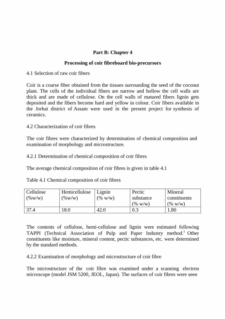
Part B: Chapter 4
Processing of coir fibreboard bio-precursors
4.1 Selection of raw coir fibers
Coir is a coarse fiber obtained from the tissues surrounding the seed of the coconut
plant. The cells of the individual fibers are narrow and hollow the cell walls are
thick and are made of cellulose. On the cell walls of matured fibers lignin gets
deposited and the fibers become hard and yellow in colour. Coir fibers available in
the Jorhat district of Assam were used in the present project for synthesis of
ceramics.
4.2 Characterization of coir fibres
The coir fibres were characterized by determination of chemical composition and
examination of morphology and microstructure.
4.2.1 Determination of chemical composition of coir fibres
The average chemical composition of coir fibres is given in table 4.1
Table 4.1 Chemical composition of coir fibres
Cellulose
(%w/w)
Hemicellulose
(%w/w)
Lignin
(% w/w)
Pectic
substance
(% w/w)
Mineral
constituents
(% w/w)
37.4 18.0 42.0 0.3 1.80
The contents of cellulose, hemi-cellulose and lignin were estimated following
TAPPI (Technical Association of Pulp and Paper Industry method.1 Other constituents like moisture, mineral content, pectic substances, etc. were determined by the standard methods.
4.2.2 Examination of morphology and microstructure of coir fibre
The microstructure of the coir fibre was examined under a scanning electron
microscope (model JSM 5200, JEOL, Japan). The surfaces of coir fibres were seen

to be very rough shallow pits were visible. The representative microstructures of
coir fibre are presented in Fig. 4.1. The average diameter of coir fibre was found to
be around 275 m, which is well within the ranges of fibre diameter (100-450 m)
Fig. 4.1 Typical scanning electron micrographs of coir fibre; cellular
morphology of a single filament of coir fibre was evident in axial (L) and in
cross sectional (R) views
reported in the published literature.2 The cellular morphology was also clearly visible in the cross-sectional view. The cell diameter and the strut were seen to be
varied from 2.3 to 11.8 and 1.8 to 1.5 m, respectively. Other authors also noticed
similar microstructures of coir fibres.2
4.3 Preparation of coir fibreboard as bio-precursor to ceramics
Coir fibres were suitably processed for preparation of rectangular boards and the coir fibreboards were used as bio-precursors to ceramics in the present work. In the fibreboard making cellulose acetate (Loba Chemicals, India) was used as the
binder. The binder was selected on the basis of the fact that no vast difference in the behavior of the binder and the coir fibre was observed during thermal analysis (discussed in the following section on carbon template making).Well matured dry
fibres were chopped to 1.0-1.5 cm of length and mixed with the binder in a way similar to powder mixing followed during processing of ceramics. 20% solution of the binder in acetone was used in order to achieve better mixing of the fibres and the binders. The mixture was then taken in a suitable mould (30 cm x 30 cm x 10
cm) and pressed in a hydraulic press at a temperature of 135oC at a pressure of
around130 kg cm-2. After the pressure was released the boards were kept in air for
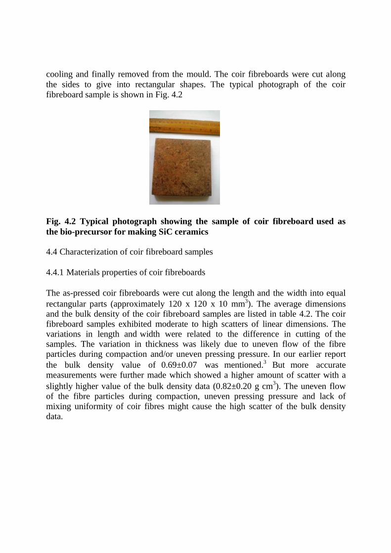
cooling and finally removed from the mould. The coir fibreboards were cut along
the sides to give into rectangular shapes. The typical photograph of the coir
fibreboard sample is shown in Fig. 4.2
Fig. 4.2 Typical photograph showing the sample of coir fibreboard used as
the bio-precursor for making SiC ceramics
4.4 Characterization of coir fibreboard samples
4.4.1 Materials properties of coir fibreboards
The as-pressed coir fibreboards were cut along the length and the width into equal
rectangular parts (approximately 120 x 120 x 10 mm3). The average dimensions and the bulk density of the coir fibreboard samples are listed in table 4.2. The coir fibreboard samples exhibited moderate to high scatters of linear dimensions. The variations in length and width were related to the difference in cutting of the samples. The variation in thickness was likely due to uneven flow of the fibre particles during compaction and/or uneven pressing pressure. In our earlier report
the bulk density value of 0.69±0.07 was mentioned.3 But more accurate measurements were further made which showed a higher amount of scatter with a
slightly higher value of the bulk density data (0.82±0.20 g cm3). The uneven flow
of the fibre particles during compaction, uneven pressing pressure and lack of mixing uniformity of coir fibres might cause the high scatter of the bulk density data.

Table 4.2. Characteristics of coir fibreboard bio-precursors used in the
present work
Dimension (mm) Bulk Density
(g cm-3) Length Width Thickness
129.7±10.7 122.6±10.7 11.9±1.6 0.82±0.20
4.4.2 Microstructure of coir fibreboards
Respective samples for microstructure examination were prepared by cutting
specimens from different sections. Coir fibreboard test specimens were taken from
the sections parallel and perpendicular to the hot pressing direction. Microstructure
of the samples was examined using scanning electron microscopy (model JSM
5200, JEOL, Japan).
Microstructure examination of coir fibreboard samples revealed that the coir fibres
were highly piled and their distribution was not very uniform. Representative SEM
micrographs are presented in Fig. 4.3. A thin layer was seen to be deposited on the
top surface of the samples and it was likely to be related to the cellulose acetate
binder phase. The cross-sectional view revealed much of the sample inner
structure. Many voids were seen to be present. The voids were of moderate to large
dimensions (100 to 450 m). The microstructure inhomogeneity observed in the
Fig. 4.3 SEM photomicrographs of coir fibreboard samples showing sectional
views- (L) along the direction perpendicular to hot-pressing axis and (R) along
the direction parallel to the hot pressing direction; in the right-handed view
the microstructure of an individual fibre is shown in the blown up portion
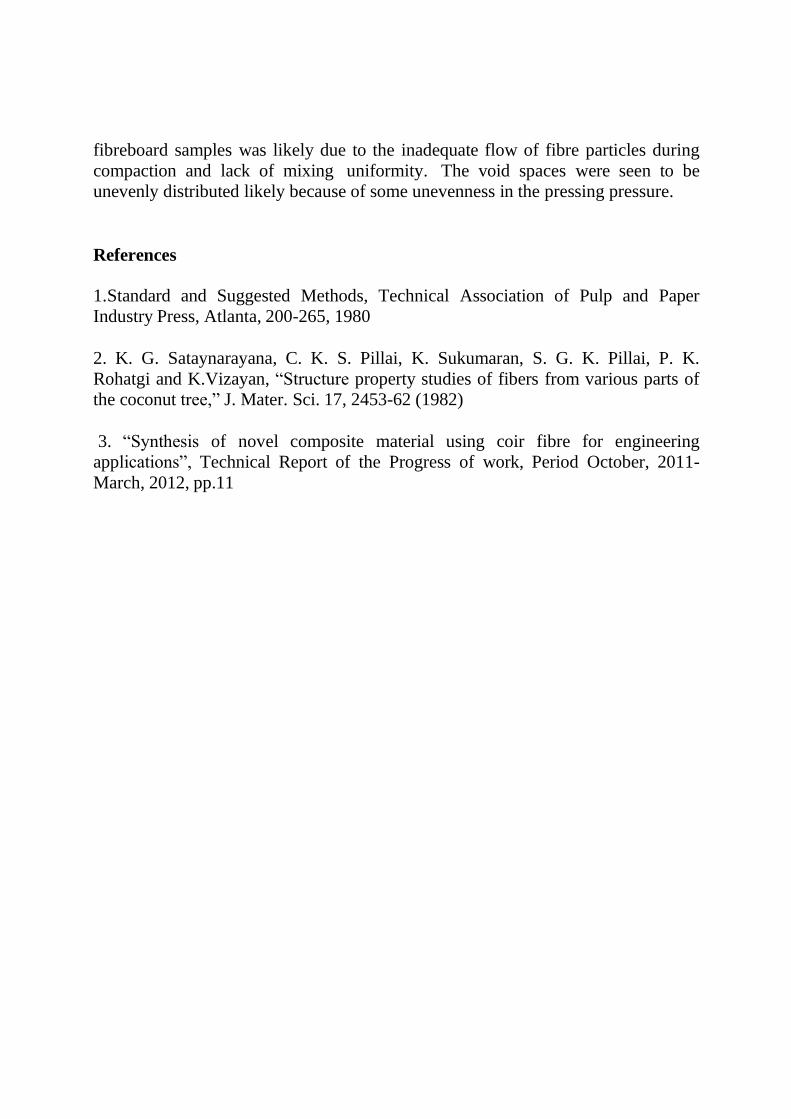
fibreboard samples was likely due to the inadequate flow of fibre particles during
compaction and lack of mixing uniformity. The void spaces were seen to be
unevenly distributed likely because of some unevenness in the pressing pressure.
References
1. Standard and Suggested Methods, Technical Association of Pulp and Paper
Industry Press, Atlanta, 200-265, 1980
2. K. G. Sataynarayana, C. K. S. Pillai, K. Sukumaran, S. G. K. Pillai, P. K.
Rohatgi and K.Vizayan, “Structure property studies of fibers from various parts of
the coconut tree,” J. Mater. Sci. 17, 2453-62 (1982)
3. “Synthesis of novel composite material using coir fibre for engineering
applications”, Technical Report of the Progress of work, Period October, 2011-
March, 2012, pp.11
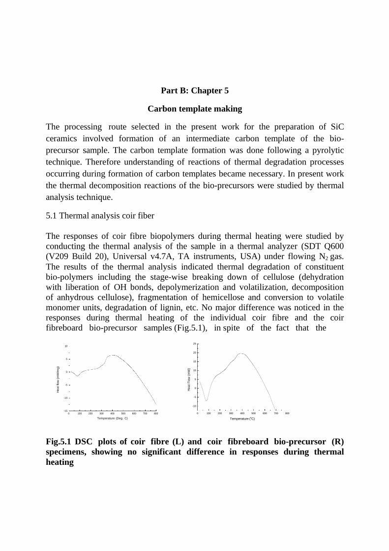
Part B: Chapter 5
Carbon template making
The processing route selected in the present work for the preparation of SiC
ceramics involved formation of an intermediate carbon template of the bio-
precursor sample. The carbon template formation was done following a pyrolytic
technique. Therefore understanding of reactions of thermal degradation processes
occurring during formation of carbon templates became necessary. In present work
the thermal decomposition reactions of the bio-precursors were studied by thermal
analysis technique.
5.1 Thermal analysis coir fiber
The responses of coir fibre biopolymers during thermal heating were studied by
conducting the thermal analysis of the sample in a thermal analyzer (SDT Q600
(V209 Build 20), Universal v4.7A, TA instruments, USA) under flowing N2 gas.
The results of the thermal analysis indicated thermal degradation of constituent
bio-polymers including the stage-wise breaking down of cellulose (dehydration
with liberation of OH bonds, depolymerization and volatilization, decomposition
of anhydrous cellulose), fragmentation of hemicellose and conversion to volatile
monomer units, degradation of lignin, etc. No major difference was noticed in the
responses during thermal heating of the individual coir fibre and the coir
fibreboard bio-precursor samples (Fig.5.1), in spite of the fact that the
10
5
0
-5
-10
-15
0 100 200 300 400 500 600 700 800
Temperature (Deg. C)
25
20
15
10
5
0
-5
-10
0 100 200 300 400 500 600 700 800
Temperature (oC)
Fig.5.1 DSC plots of coir fibre (L) and coir fibreboard bio-precursor (R)
specimens, showing no significant difference in responses during thermal
heating
Hea
t flow
(m
W/m
g)
He
at F
low
(m
W)
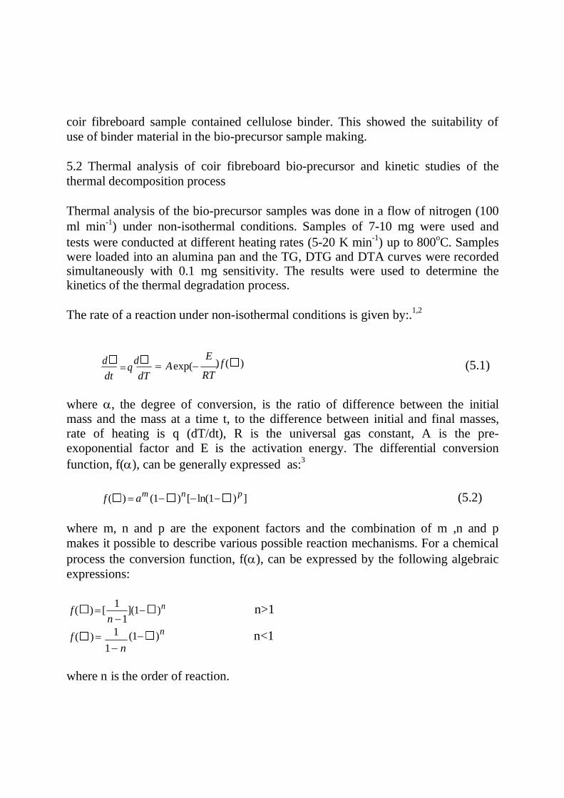
coir fibreboard sample contained cellulose binder. This showed the suitability of
use of binder material in the bio-precursor sample making.
5.2 Thermal analysis of coir fibreboard bio-precursor and kinetic studies of the
thermal decomposition process
Thermal analysis of the bio-precursor samples was done in a flow of nitrogen (100
ml min-1) under non-isothermal conditions. Samples of 7-10 mg were used and
tests were conducted at different heating rates (5-20 K min-1
) up to 800oC. Samples
were loaded into an alumina pan and the TG, DTG and DTA curves were recorded simultaneously with 0.1 mg sensitivity. The results were used to determine the kinetics of the thermal degradation process.
The rate of a reaction under non-isothermal conditions is given by:.1,2
d q
d
dt dT A exp(
E ) f ( )
RT (5.1)
where , the degree of conversion, is the ratio of difference between the initial mass and the mass at a time t, to the difference between initial and final masses, rate of heating is q (dT/dt), R is the universal gas constant, A is the pre-
exoponential factor and E is the activation energy. The differential conversion
function, f(), can be generally expressed as:3
f ( ) am (1 )n
[ln(1 ) p ] (5.2)
where m, n and p are the exponent factors and the combination of m ,n and p
makes it possible to describe various possible reaction mechanisms. For a chemical
process the conversion function, f(), can be expressed by the following algebraic
expressions:
f ( ) [
f ( )
1
n 1
1
](1 )n
(1 ) n
n>1
n<1 1 n
where n is the order of reaction.
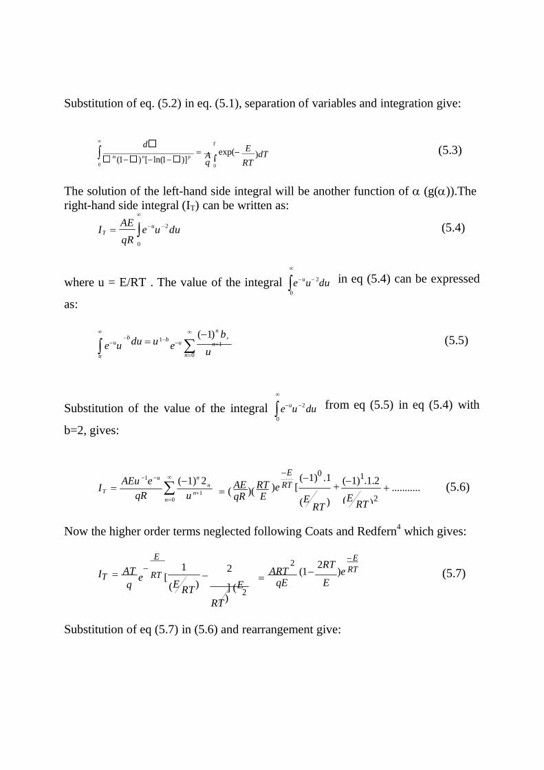
A
0
T
2
Substitution of eq. (5.2) in eq. (5.1), separation of variables and integration give:
d
m (1 ) n
[ln(1 )] p
T
exp(
q 0
E
)dT RT
(5.3)
The solution of the left-hand side integral will be another function of (g()).The
right-hand side integral (IT) can be written as:
I AE
e u
u 2
du qR
0
(5.4)
where u = E/RT . The value of the integral eu
u2
du 0
in eq (5.4) can be expressed
as:
euu
b
du u
1b
eu (1)
n b
n1
(5.5) u n0 u
Substitution of the value of the integral eu
u 2
du 0
from eq (5.5) in eq (5.4) with
b=2, gives:
IT
AEu 1e u
qR
n0
(1)n 2
u n1
( AE
)( RT
qR E
E
)e RT [
(1)0
.1
(E RT
)
(1)1.1.2
...........
(5.6)
Now the higher order terms neglected following Coats and Redfern4
which gives:
IT
E
AT e
RT [
q (E
1
RT )
2
] (E
RT )
ART
qE
E
(1 2RT
)e RT
E
(5.7)
Substitution of eq (5.7) in (5.6) and rearrangement give:
(E RT )
2
n
n
2
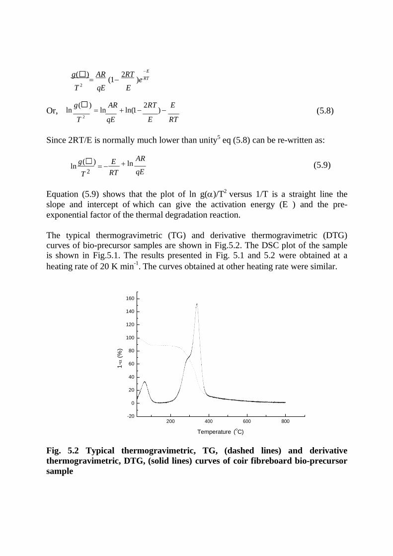
g ( ) AR 2RT E
(1 )e RT
T 2
qE E
Or, ln g( )
ln AR
ln(1 2RT
) E
(5.8) T
2 qE E RT
Since 2RT/E is normally much lower than unity5 eq (5.8) can be re-written as:
ln g( )
E
T 2 RT
ln AR
qE
(5.9)
Equation (5.9) shows that the plot of ln g()/T2 versus 1/T is a straight line the
slope and intercept of which can give the activation energy (E ) and the pre-
exponential factor of the thermal degradation reaction.
The typical thermogravimetric (TG) and derivative thermogravimetric (DTG) curves of bio-precursor samples are shown in Fig.5.2. The DSC plot of the sample is shown in Fig.5.1. The results presented in Fig. 5.1 and 5.2 were obtained at a
heating rate of 20 K min-1
. The curves obtained at other heating rate were similar.
160
140
120
100
80
60
40
20
0
-20 200 400 600 800
Temperature (oC)
Fig. 5.2 Typical thermogravimetric, TG, (dashed lines) and derivative
thermogravimetric, DTG, (solid lines) curves of coir fibreboard bio-precursor
sample
1-
(%
)
In the DSC plot (Fig. 5.1 (R)) an endothermic peak appeared at temperatures
<100oC was due to evaporation of surface water. The DTG curve of the bio-
precursor showed a peak at around 75oC for the same reason (Fig.5.2). At ~ 390 oC an exothermic peak appeared in the DSC scan. In the DTG plot a sharp peak was
observed at 340oC. The accompanying TG curve (Fig. 5.2) showed that the bio-
precursor samples exhibited maximum weight loss at 250 - 500oC and the recorded
weight loss was around 70%. The thermal decomposition behaviour of cellulose ~ one of the main constituents of the bio-precursors ~ was studied by several
researchers.6-7According to these reports cellulose breaks down in a step-wise
manner; at temperatures < 300oC dehydration is the favoured exothermic reaction
and OH bonds are liberated to form double and conjugated double bonds
stabilizing the structure. At 300-350oC endothermic depolymerisation and
volatilization of reaction products take place. At around 370oC an exothermic reaction occurs due to decomposition of anhydrous cellulose and it involves breaking of C-O and C-C bonds within the ring structure with evolution of water, CO and CO2; formation of char also takes place. Cellulose loses around 75% of its
weight at 245-475oC due to escape of volatiles like H2O, CO2 and other gaseous hydrocarbons. The thermal degradation behaviour of hemicellulose ~ another bio-
polymeric constituent of the bio-precursors ~ was reported to be slightly different.8
The decomposition of hemicellulose follows a step wise manner ~ a mild
endothermic reaction starts at 200oC and completes at 320oC and this is followed by an exothermic reaction. Hemicellulose was reported to lose around 50% of its
weight at 200-370oC due to decomposition of the polymer into soluble fragments and/or conversion into monomer units that further decompose into volatile products. As compared to cellulose, hemicellulose gives rise to more volatiles, less tar and char. The components of tar are organic acids such as acetic acid, formic acid and a few furfural derivatives. The thermal degradation process of lignin ~
also another bio-polymeric constituent of the bio-precursors ~ was reported to be
very similar to that of cellulose and hemicellulose.8,9 The step-wise decomposition
process is characterized by an endothermic reaction occurring at 100-180oC and
two exothermic reactions ~ the first one starts at 280oC and ends at 390oC and the
second one has a peak at a higher temperature of 420oC. The endothermic reaction is due to removal of water and the exothermic reactions are associated with dehydration and formation of char. The degradation of lignin is reported to end at
around 470oC. In the present work bio-precursors contain cellulose, hemicellulose
and lignin as the major constituents; the responses of the bio-precursors during heating are therefore expected to reflect the characteristics of thermal degradation of constituent biopolymers. For the bio-precursor samples the thermal decomposition associated with maximum loss in weight was a highly exothermic
process and it occurred at the temperature range of 250 to 500oC.

The kinetic parameters of the thermal degradation process (involving maximum
weight loss) of the coir fibreboard bio-precursor samples were determined by eq
(5.9).
The expression for g() was determined at different values of n, the order of
thermal degradation reaction. The values of g() at different temperature (T) and
hence, g()/T2, were determined for a given reaction order, n. g()/T
2 values were
plotted against 1/T for the given order of reaction (n) and the coefficient of linear
regression, R2, was determined, assuming the plot to be linear. The different values
of R2 were plotted against n. The plots could be described by an empirical polynomial of second order (Fig. 5.3(L)). Differentiation of the polynomial and
equating the derivative d(R2)/dn = 0, gave the value of n (order of reaction) for
which the value of R2
is maximum. Then the expression for g() was determined
for the known value of n, g()/T2 were determined at different values of T and the activation energy (E) and the pre-exponential factor (A) of the thermal degradation reaction was determined from the linear plot with the help of eq (5.9) (Fig. 5.3(R
)).
-10
0.95
-11
-12
0.90
-13
-14
-15
0.85 -16
-17
0 2 4
n
-18
0.0015 0.0016 0.0017 0.0018 0.0019 0.0020
1/T2 (1/K)
Fig.5.3 Dependence of the coefficient of linear regression R2
on the values of n
(L ) and fitting curve of ln g( )/T2 versus 1/T (R)
E, A and n of the thermal degradation reaction of the bio-precursor were
determined using different heating rates and the average values of these parameters
are presented in Table 5.1
R2= 0.99
R2
ln (
g(
) / T
2)
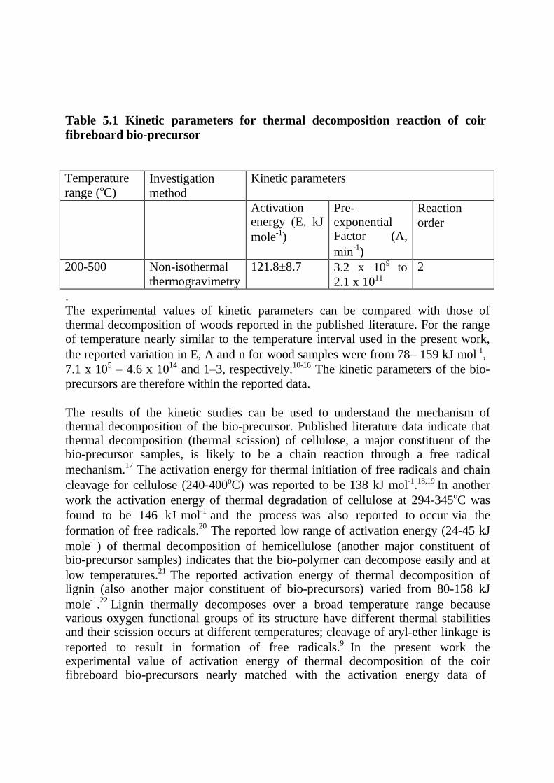
Table 5.1 Kinetic parameters for thermal decomposition reaction of coir
fibreboard bio-precursor
Temperature
range (oC) Investigation
method
Kinetic parameters
Activation energy (E, kJ
mole-1)
Pre- exponential Factor (A,
min-1
)
Reaction
order
200-500 Non-isothermal
thermogravimetry
121.8±8.7 3.2 x 10⁹ to
2.1 x 10¹¹
2
. The experimental values of kinetic parameters can be compared with those of thermal decomposition of woods reported in the published literature. For the range of temperature nearly similar to the temperature interval used in the present work,
the reported variation in E, A and n for wood samples were from 78– 159 kJ mol-1,
7.1 x 10⁵ – 4.6 x 10¹⁴ and 1–3, respectively.10-16 The kinetic parameters of the bio-
precursors are therefore within the reported data.
The results of the kinetic studies can be used to understand the mechanism of thermal decomposition of the bio-precursor. Published literature data indicate that thermal decomposition (thermal scission) of cellulose, a major constituent of the bio-precursor samples, is likely to be a chain reaction through a free radical
mechanism.17
The activation energy for thermal initiation of free radicals and chain
cleavage for cellulose (240-400oC) was reported to be 138 kJ mol-1.18,19 In another
work the activation energy of thermal degradation of cellulose at 294-345oC was
found to be 146 kJ mol-1 and the process was also reported to occur via the
formation of free radicals.20
The reported low range of activation energy (24-45 kJ
mole-1
) of thermal decomposition of hemicellulose (another major constituent of bio-precursor samples) indicates that the bio-polymer can decompose easily and at
low temperatures.21 The reported activation energy of thermal decomposition of lignin (also another major constituent of bio-precursors) varied from 80-158 kJ
mole-1
.22
Lignin thermally decomposes over a broad temperature range because various oxygen functional groups of its structure have different thermal stabilities and their scission occurs at different temperatures; cleavage of aryl-ether linkage is
reported to result in formation of free radicals.9 In the present work the experimental value of activation energy of thermal decomposition of the coir fibreboard bio-precursors nearly matched with the activation energy data of

thermal degradation of their constituent bio-polymers, indicating that the process
of thermal decomposition of the bio-precursor involved reactions occurring
through a free radical mechanism.
5.3 Preparation of carbon template by pyrolytic method
Carbon templates of the coir fibreboard bio-precursor were prepared
following the pyrolytic technique. Pyrolysis of bio-precursor samples was carried out in a controlled atmosphere furnace (Steadfast International, Kolkata, India) under flowing nitrogen gas (99.997%, Praxair India (P) Ltd., Kolkata, India) with a
flow rate of 25 ml min-1
at a pressure slightly higher than the atmospheric pressure.
The pyrolysis furnace set-up used for this purpose is shown Fig. 5.4. Pyrolysis
experiments were carried out at different heating rates and the peak temperature
was kept constant at 800oC.
Fig. 5.4 Photograph of the pyrolysis set-up used for carbon template making
Extremely slow heating and large processing time was chosen in order to minimize the severity of the decomposition reactions of bio-polymers and retention of shape
of the carbon template produced. A heating rate of 50oC h-1 was initially used up to
90oC with a dwell time of 5 h at 90
oC mainly for drying; but during the stages of
major mass loss involving different bio-polymeric degradation reactions, low heating rates were maintained to avoid structural disintegration. A heating rate of
15oC h-1 was applied from 90 to 200oC with a dwell time of 0.5 h at 200oC; this
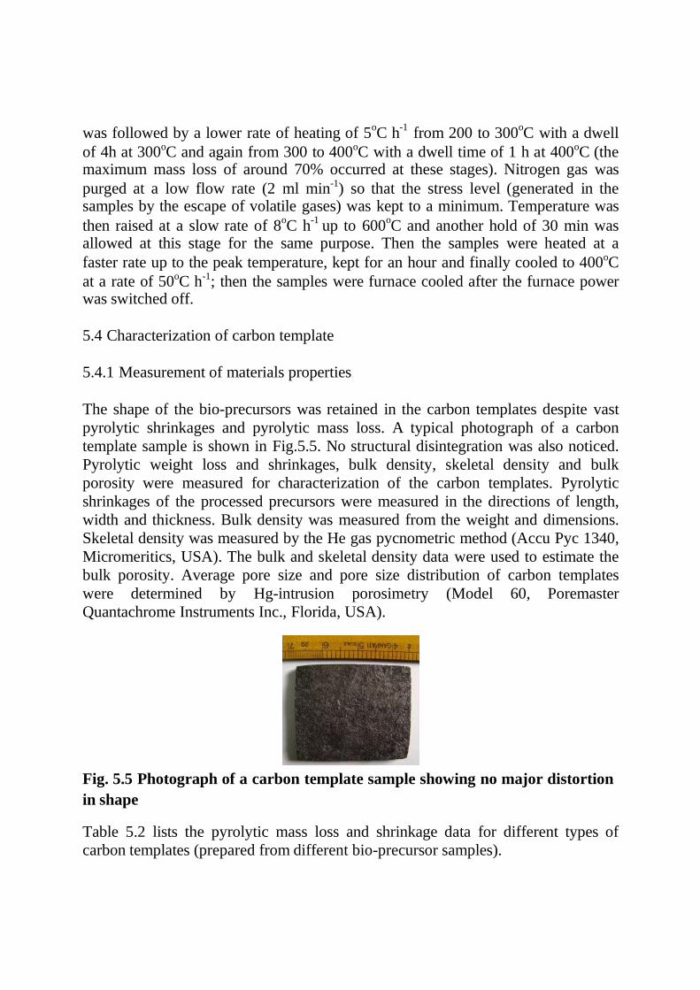
was followed by a lower rate of heating of 5oC h
-1 from 200 to 300
oC with a dwell
of 4h at 300oC and again from 300 to 400oC with a dwell time of 1 h at 400oC (the maximum mass loss of around 70% occurred at these stages). Nitrogen gas was
purged at a low flow rate (2 ml min-1) so that the stress level (generated in the samples by the escape of volatile gases) was kept to a minimum. Temperature was
then raised at a slow rate of 8oC h
-1 up to 600
oC and another hold of 30 min was
allowed at this stage for the same purpose. Then the samples were heated at a
faster rate up to the peak temperature, kept for an hour and finally cooled to 400oC
at a rate of 50oC h-1; then the samples were furnace cooled after the furnace power was switched off.
5.4 Characterization of carbon template
5.4.1 Measurement of materials properties
The shape of the bio-precursors was retained in the carbon templates despite vast
pyrolytic shrinkages and pyrolytic mass loss. A typical photograph of a carbon
template sample is shown in Fig.5.5. No structural disintegration was also noticed.
Pyrolytic weight loss and shrinkages, bulk density, skeletal density and bulk
porosity were measured for characterization of the carbon templates. Pyrolytic
shrinkages of the processed precursors were measured in the directions of length,
width and thickness. Bulk density was measured from the weight and dimensions.
Skeletal density was measured by the He gas pycnometric method (Accu Pyc 1340,
Micromeritics, USA). The bulk and skeletal density data were used to estimate the
bulk porosity. Average pore size and pore size distribution of carbon templates
were determined by Hg-intrusion porosimetry (Model 60, Poremaster
Quantachrome Instruments Inc., Florida, USA).
Fig. 5.5 Photograph of a carbon template sample showing no major distortion
in shape
Table 5.2 lists the pyrolytic mass loss and shrinkage data for different types of
carbon templates (prepared from different bio-precursor samples).
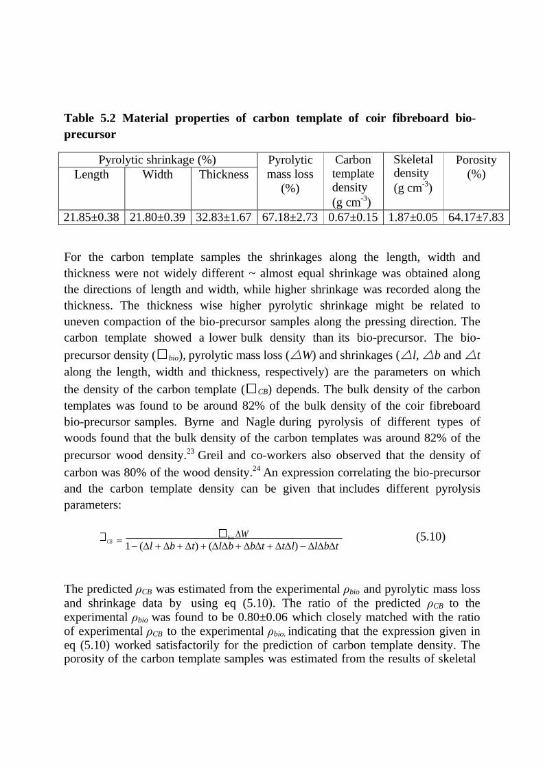
Table 5.2 Material properties of carbon template of coir fibreboard bio-
precursor
Pyrolytic shrinkage (%) Pyrolytic
mass loss
(%)
Carbon template density
(g cm-3)
Skeletal density
(g cm-3)
Porosity
(%) Length Width Thickness
21.85±0.38 21.80±0.39 32.83±1.67 67.18±2.73 0.67±0.15 1.87±0.05 64.17±7.83
For the carbon template samples the shrinkages along the length, width and
thickness were not widely different ~ almost equal shrinkage was obtained along
the directions of length and width, while higher shrinkage was recorded along the
thickness. The thickness wise higher pyrolytic shrinkage might be related to
uneven compaction of the bio-precursor samples along the pressing direction. The
carbon template showed a lower bulk density than its bio-precursor. The bio-
precursor density ( bio), pyrolytic mass loss (W) and shrinkages (l, b and t
along the length, width and thickness, respectively) are the parameters on which
the density of the carbon template ( CB) depends. The bulk density of the carbon
templates was found to be around 82% of the bulk density of the coir fibreboard
bio-precursor samples. Byrne and Nagle during pyrolysis of different types of
woods found that the bulk density of the carbon templates was around 82% of the
precursor wood density.23 Greil and co-workers also observed that the density of
carbon was 80% of the wood density.24 An expression correlating the bio-precursor
and the carbon template density can be given that includes different pyrolysis
parameters:
CB bio W
1 (l b t) (lb bt tl) lbt (5.10)
The predicted ρCB was estimated from the experimental ρbio and pyrolytic mass loss
and shrinkage data by using eq (5.10). The ratio of the predicted ρCB to the experimental ρbio was found to be 0.80±0.06 which closely matched with the ratio of experimental ρCB to the experimental ρbio, indicating that the expression given in eq (5.10) worked satisfactorily for the prediction of carbon template density. The porosity of the carbon template samples was estimated from the results of skeletal
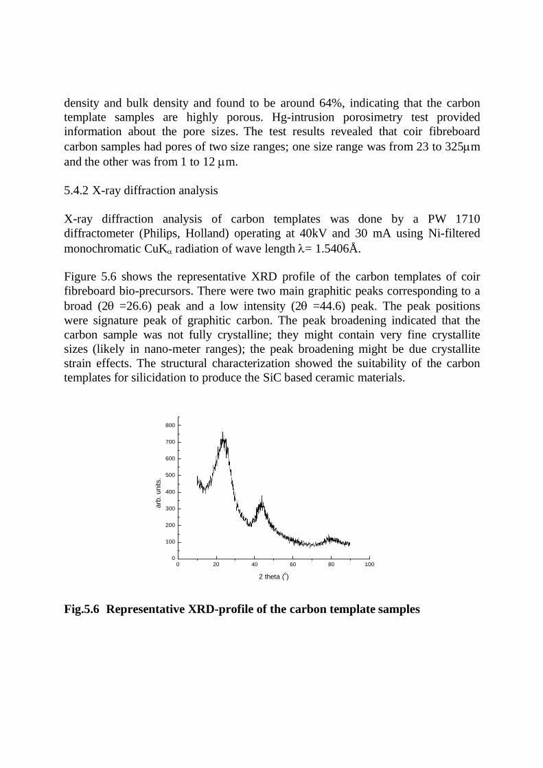
density and bulk density and found to be around 64%, indicating that the carbon
template samples are highly porous. Hg-intrusion porosimetry test provided
information about the pore sizes. The test results revealed that coir fibreboard
carbon samples had pores of two size ranges; one size range was from 23 to 325m
and the other was from 1 to 12 m.
5.4.2 X-ray diffraction analysis
X-ray diffraction analysis of carbon templates was done by a PW 1710
diffractometer (Philips, Holland) operating at 40kV and 30 mA using Ni-filtered
monochromatic CuKradiation of wave length = 1.5406Å.
Figure 5.6 shows the representative XRD profile of the carbon templates of coir
fibreboard bio-precursors. There were two main graphitic peaks corresponding to a
broad (2=26.6) peak and a low intensity (2=44.6) peak. The peak positions
were signature peak of graphitic carbon. The peak broadening indicated that the
carbon sample was not fully crystalline; they might contain very fine crystallite
sizes (likely in nano-meter ranges); the peak broadening might be due crystallite
strain effects. The structural characterization showed the suitability of the carbon
templates for silicidation to produce the SiC based ceramic materials.
800
700
600
500
400
300
200
100
0 0 20 40 60 80 100
2 theta (o)
Fig.5.6 Representative XRD-profile of the carbon template samples
arb
. u
nits.
5.4.3 Microstructure examination
Microstructure of carbon templates was examined under a scanning electron
microscope (SE 440, Leo-Cambridge, UK). Microstructure examination revealed
that the morphology of the bio-fibres was perfectly maintained in the carbon
template of coir fibreboard sample. The representative microstructure was
presented in Fig. 5.7.
.
Fig. 5.7 SEM/SE images of carbon templates of coir fibreboard showing the
microstructures of sample sections perpendicular (L) and parallel (R) to the
pressing direction. Some details of the hollow fibre structure are shown in the
inset.
Microstructural view of the section perpendicular to the pressing direction revealed
some presence of a thin coat likely to be related to the cellulose acetate binder used
during preparation of bio-precursor samples. The carbonized coir fibres were seen
to be randomly piled. Examination of the microstructure of the section parallel to
the pressing direction revealed more details of the internal structure of the samples.
Pores were seen to be formed mostly by the networking of the carbonized coir
fibres. Sizes of the pores varied from 110 to 250 m. The fibres in the carbon
templates were observed to be of varying sizes (from 45 to 214 m). The average
diameter of the carbon fibres was found to be ~90 m. The fibres were seen to be
hollow containing interconnected channel pores of sizes varying from 5 to 14 m
and with thickness of the pore wall ranging from 2 to 3 m.
5.4.4 Mechanical property measurement
Rectangular test specimens (35 x 6 x 5 mm3) were prepared from the carbon templates by cutting. One of the surfaces perpendiculars to the pressing direction was selected as the tensile face. The room temperature fracture strength was
measured in three point bending mode (span: 30 mm; loading rate 0.5 mm min-1
) in Universal Testing Machine (Model 1123, Instron Corp. Canton, MA, USA). The loaded cross section of the test sample was larger than what was commonly used (3
x 4 mm2) to account for the macroscopic non-uniformity of the cellular structure of the materials. Average values of 10 measurements were taken for flexural strength determination.
The 3 point bending strength of the carbon templates was found to be 9.2 ±0.8
MPa. The mechanical test results indicated that the carbon template samples had
sufficient handling strength to avoid any structural disintegration in the subsequent
stages of processing (ceramization).
References
1. L. Vlaev, N. Nedelchev, K. Gyurova and M. A. Zagorcheva, “Comparative
study of non-isothermal kinetics of decomposition of calcium oxalate
monohydrate,” J. Anal. Appl. Pyrolysis 81, 253-62 (2008).
2. A. Atanassov, S. Genieva and L. Vlaev, “Study of the thermooxidative
degradation kinetics of tetrafluroethelene-ethelene co-polymer filled with rice husk
ash,” Polym. Plast .Technol. Eng. 49 541-54 (2010)
3. J. Sestak and G. Berggren, “Study of the kinetics of the mechanism of solid state
reactions at increasing temperatures,” Thermochim. Acta. 3[1] 1-12 (1971)
4. A.W. Coats and J. P. Redfern, “Kinetic parameters from thermogravimetric
data,” Nature (London) 201 68-9 (1964)
5. V. Georgieva, D. Zvezdova and L. Vlaev, “Non-isothermal kinetics of thermal
degradation of chitin”, J. Therm. Anal. Calorim. 111 763-71 (2013)
6. D. F. Arseneau, “Competitive reactions in thermal decomposition of cellulose,”
Can. J. Chem. 49 632-8 (1971).
7. P. Jandura, B. Riedl and B. V. Kokta, “Thermal degradation behaviour of
cellulose fibres partially esterified with some long chain organic acids,” Polym .
Degrad. Stab.,70 387-94 (2000).
8. V. Strezov, B. Moghtaderi and J. A. Lucas, “Thermal study of decomposition of
selected biomass samples,” J. Therm. Anal. Calorim., 72(1) 1041-8 (2003).
9. M. Brebu and C. Vasile, “Thermal degradation of lignin-A review,” Cellul.
Chem. Technol., 44(9) 353-63 (2010).
10. W. L. Wang, X. Y. Ren, Y. Z. Che, J. M. Chang and J. S. Gou, “Kinetics
and FTIR characteristics of the pyrolysis process of poplar wood,” For. Sci.
Pract., 15(1) 70-5 (2013).
11. W. H. Park and K. B. Yoon, “Optimization of pyrolysis properties using TGA
and cone calorimeter test,” J. Therm. Sci., 22(2) 168-73 (2013).
12. C. Vovelle, J. L. Delfau and H. Mellottee, “Kinetics of thermal degradation of
wood and cellulose by TGA comparison of the calculation techniques,” Prepr. Pap.
Am. Chem. Soc. Div. Fuel Chem., 28(5) 291-300 (1983).
13. D. Q. Tran and C. Rai, “A kinetic model for pyrolysis of Douglas fir bark,”
Fuel, 57(5) 293-8 (1978).
14. R. Zakrzewski, “Pyrolysis kinetics of wood comparison of iso and polythermal
thermogravimetric methods,” Electr. J. Polish. Agric. Univ. Series: Wood
technology, 6(2) (2003).
15. K. Slopiecka, P. Bartocci and F. Fantozzi, “Thermogravimetric analysis and
kinetic study of poplar wood pyrolysis,” Appl. Energy, 97, 491-7 (2012).
16. R. Font, J. A. Conesa, J. Molto and M. Munoz, “Kinetics of pyrolysis and
combustion of pine needles and cones,” J. Anal. Appl. Pyrolysis, 85(1-2) 276-86
(2009).
17. M. M. Tang and R. Bacon, “Carbonization of cellulose fibers- I, low
temperature pyrolysis,” Carbon, 2, 211-20 (1964).

18. N. Grassie, E. J. Murry and P. A. Holmes, “The thermal degradation of poly (-
(D) -hydroxy butyric acid) : part 2- changes in molecular weight,” Polym.
Degrad. Stab., 6(2) 95-103 (1984).
19. J. C. Arthur and O. Hinogosa, “Thermal initiation of free radicals in cotton
cellulose,” Textile Res. J., 36, 385-7 (1966).
20. M. V. Ramiah, “Thermogravimetric and differential thermal analysis of
cellulose, hemi-cellulose and lignin,” J. Appl. Polymer Sci., 14, 1323-37 (1970).
21. H. Peng, Z. Hu, J. Zhang, Y. Liu, Y. Wan and R. Ruan, “Fractionation and
thermal characterization of hemicelluloses from bamboo (Phyllostachys Pubescens
Mazel) culm,” BioResources , 7(1) 374-90 (2012).
22. N. Marin, S. Collura, V. I. Sharypov, N. G. Beregovtsova, S. V. Baryshnikov,
B. N. Kutnetzov et al. “Copyrolysis of wood biomass and synthetic polymer
mixture part II: characterisation of the liquid phases,” J. Anal. Appl. Pyrolysis,
65(1) 41-55 (2002).
23. C. E. Byrne and D. C. Nagle, “Carbonization of wood for advanced materials
applications,” Carbon, 35(2) 259-66 (1997).
24. P. Greil, “Biomorphous ceramics from lignocellulosics,” J. Eur. Ceram. Soc.
21(2) 105-18 (2001).
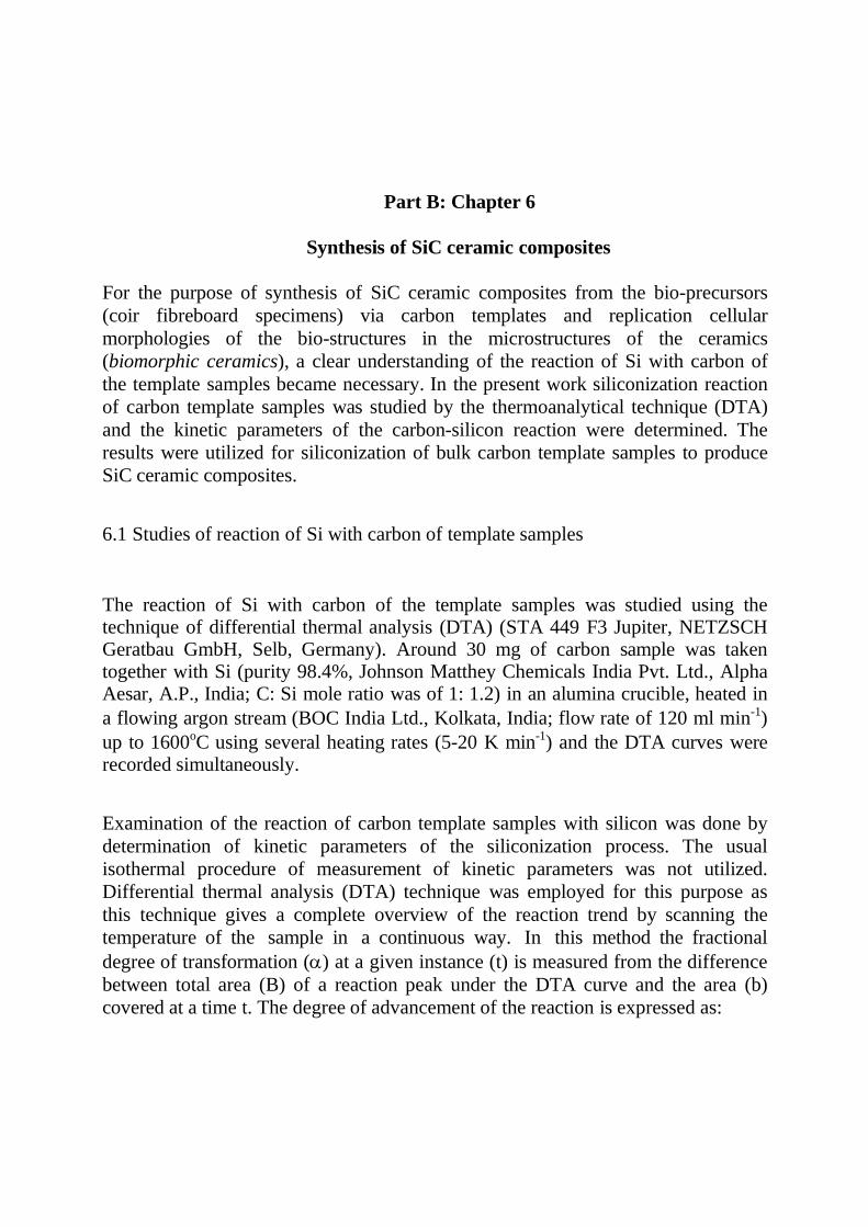
Part B: Chapter 6
Synthesis of SiC ceramic composites
For the purpose of synthesis of SiC ceramic composites from the bio-precursors
(coir fibreboard specimens) via carbon templates and replication cellular
morphologies of the bio-structures in the microstructures of the ceramics
(biomorphic ceramics), a clear understanding of the reaction of Si with carbon of
the template samples became necessary. In the present work siliconization reaction
of carbon template samples was studied by the thermoanalytical technique (DTA)
and the kinetic parameters of the carbon-silicon reaction were determined. The
results were utilized for siliconization of bulk carbon template samples to produce
SiC ceramic composites.
6.1 Studies of reaction of Si with carbon of template samples
The reaction of Si with carbon of the template samples was studied using the technique of differential thermal analysis (DTA) (STA 449 F3 Jupiter, NETZSCH Geratbau GmbH, Selb, Germany). Around 30 mg of carbon sample was taken together with Si (purity 98.4%, Johnson Matthey Chemicals India Pvt. Ltd., Alpha Aesar, A.P., India; C: Si mole ratio was of 1: 1.2) in an alumina crucible, heated in
a flowing argon stream (BOC India Ltd., Kolkata, India; flow rate of 120 ml min-1)
up to 1600oC using several heating rates (5-20 K min-1) and the DTA curves were recorded simultaneously.
Examination of the reaction of carbon template samples with silicon was done by
determination of kinetic parameters of the siliconization process. The usual
isothermal procedure of measurement of kinetic parameters was not utilized.
Differential thermal analysis (DTA) technique was employed for this purpose as
this technique gives a complete overview of the reaction trend by scanning the
temperature of the sample in a continuous way. In this method the fractional
degree of transformation () at a given instance (t) is measured from the difference
between total area (B) of a reaction peak under the DTA curve and the area (b)
covered at a time t. The degree of advancement of the reaction is expressed as:
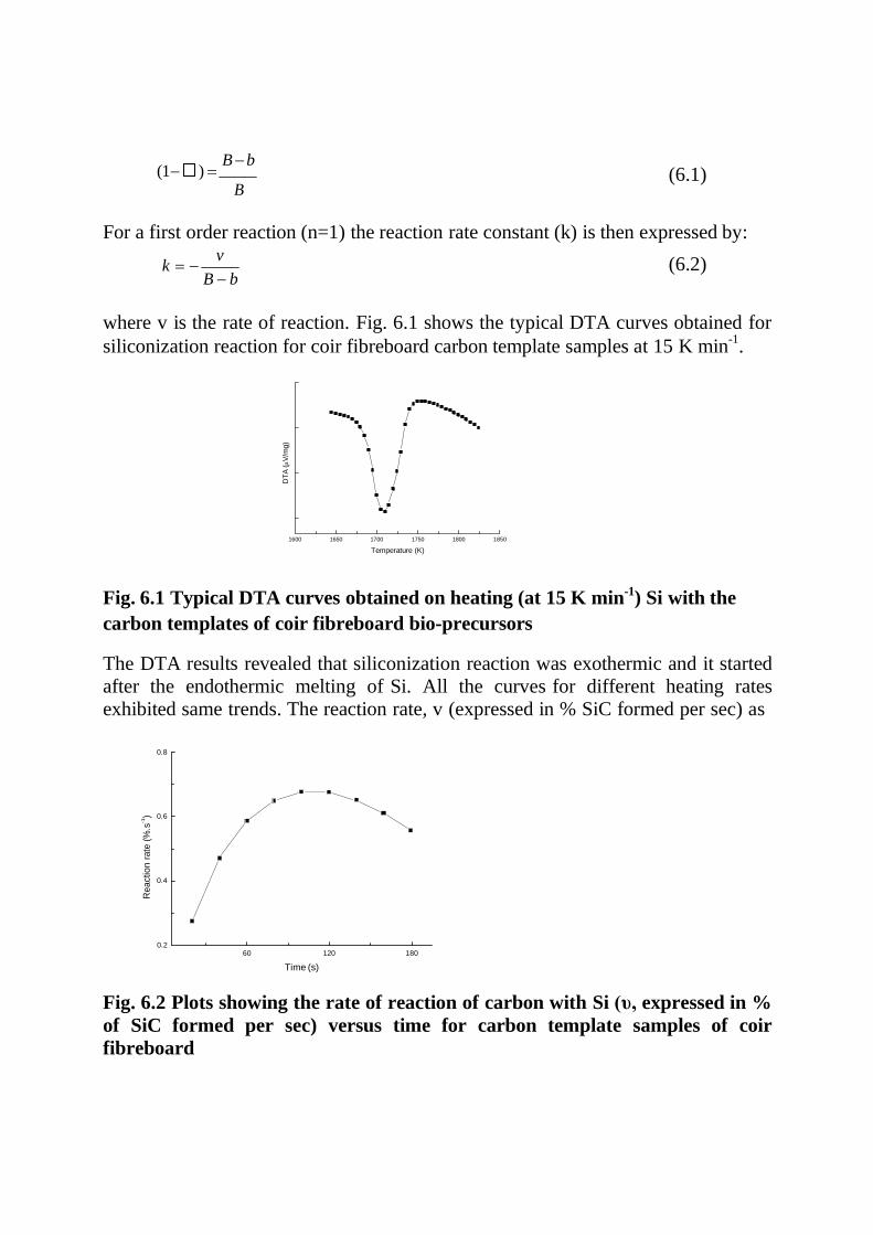
(1 ) B b
B
(6.1)
For a first order reaction (n=1) the reaction rate constant (k) is then expressed by:
k v
B b (6.2)
where v is the rate of reaction. Fig. 6.1 shows the typical DTA curves obtained for
siliconization reaction for coir fibreboard carbon template samples at 15 K min-1
.
1600 1650 1700 1750 1800 1850
Temperature (K)
Fig. 6.1 Typical DTA curves obtained on heating (at 15 K min-1) Si with the
carbon templates of coir fibreboard bio-precursors
The DTA results revealed that siliconization reaction was exothermic and it started
after the endothermic melting of Si. All the curves for different heating rates
exhibited same trends. The reaction rate, v (expressed in % SiC formed per sec) as
0.8
0.6
0.4
0.2
60 120 180
Time (s)
Fig. 6.2 Plots showing the rate of reaction of carbon with Si (υ, expressed in %
of SiC formed per sec) versus time for carbon template samples of coir
fibreboard
Re
actio
n r
ate
(%
.s-1
)
DT
A (V
/mg)
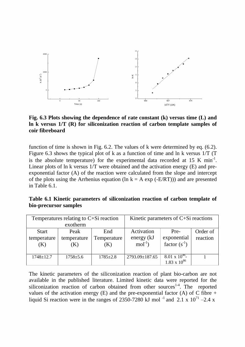
-4
4000
-3
-2
2000
-1
0
0 1
0 80 160
Time (s)
2
560 567 574
106/T (1/K)
Fig. 6.3 Plots showing the dependence of rate constant (k) versus time (L) and
ln k versus 1/T (R) for siliconization reaction of carbon template samples of
coir fibreboard
function of time is shown in Fig. 6.2. The values of k were determined by eq. (6.2). Figure 6.3 shows the typical plot of k as a function of time and ln k versus 1/T (T
is the absolute temperature) for the experimental data recorded at 15 K min-1. Linear plots of ln k versus 1/T were obtained and the activation energy (E) and pre- exponential factor (A) of the reaction were calculated from the slope and intercept
of the plots using the Arrhenius equation (ln k = A exp (-E/RT))) and are presented in Table 6.1.
Table 6.1 Kinetic parameters of siliconization reaction of carbon template of
bio-precursor samples
Temperatures relating to C+Si reaction
exotherm
Kinetic parameters of C+Si reactions
Start
temperature
(K)
Peak
temperature
(K)
End
Temperature
(K)
Activation energy (kJ
mol-1)
Pre- exponential
factor (s-1)
Order of
reaction
1748±12.7 1758±5.6 1785±2.8 2793.09±187.65 8.01 x 1046
-
1.83 x 1086
1
The kinetic parameters of the siliconization reaction of plant bio-carbon are not available in the published literature. Limited kinetic data were reported for the
siliconization reaction of carbon obtained from other sources1-4. The reported values of the activation energy (E) and the pre-exponential factor (A) of C fibre +
liquid Si reaction were in the ranges of 2350-7280 kJ mol -1 and 2.1 x 1071 –2.4 x
k.1
03
(s
-1)
ln K
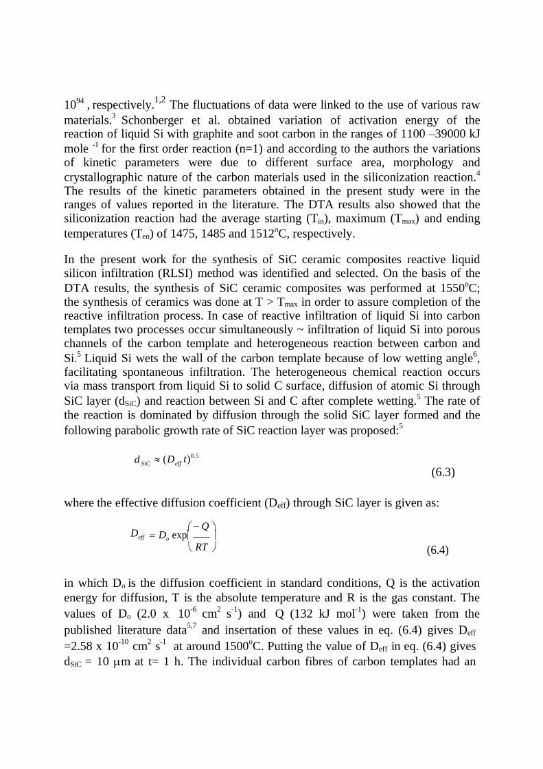
1094 , respectively.1,2
The fluctuations of data were linked to the use of various raw
materials.3
Schonberger et al. obtained variation of activation energy of the reaction of liquid Si with graphite and soot carbon in the ranges of 1100 –39000 kJ
mole -1 for the first order reaction (n=1) and according to the authors the variations of kinetic parameters were due to different surface area, morphology and
crystallographic nature of the carbon materials used in the siliconization reaction.4
The results of the kinetic parameters obtained in the present study were in the ranges of values reported in the literature. The DTA results also showed that the siliconization reaction had the average starting (Tin), maximum (Tmax) and ending
temperatures (Ten) of 1475, 1485 and 1512oC, respectively.
In the present work for the synthesis of SiC ceramic composites reactive liquid silicon infiltration (RLSI) method was identified and selected. On the basis of the
DTA results, the synthesis of SiC ceramic composites was performed at 1550oC; the synthesis of ceramics was done at T > Tmax in order to assure completion of the reactive infiltration process. In case of reactive infiltration of liquid Si into carbon templates two processes occur simultaneously ~ infiltration of liquid Si into porous channels of the carbon template and heterogeneous reaction between carbon and
Si.5 Liquid Si wets the wall of the carbon template because of low wetting angle6, facilitating spontaneous infiltration. The heterogeneous chemical reaction occurs via mass transport from liquid Si to solid C surface, diffusion of atomic Si through
SiC layer (dSiC) and reaction between Si and C after complete wetting.5 The rate of the reaction is dominated by diffusion through the solid SiC layer formed and the
following parabolic growth rate of SiC reaction layer was proposed:5
d SiC
(D
eff t)0.5
(6.3)
where the effective diffusion coefficient (Deff) through SiC layer is given as:
Q D
eff Do exp RT (6.4)
in which Do is the diffusion coefficient in standard conditions, Q is the activation
energy for diffusion, T is the absolute temperature and R is the gas constant. The
values of Do (2.0 x 10⁻⁶
cm2
s-1
) and Q (132 kJ mol-1
) were taken from the
published literature data5,7
and insertation of these values in eq. (6.4) gives Deff
=2.58 x 10⁻¹⁰
cm2
s-1
at around 1500oC. Putting the value of Deff in eq. (6.4) gives
dSiC = 10 m at t= 1 h. The individual carbon fibres of carbon templates had an

average diameter of 90 m; the fibres were hollow and the average thickness of the
pore walls of the individual carbon filaments was around 2.5 m (lower than dSiC =
10 m at t= 1 h ) and thus one hour infiltration and reaction time was sufficient for
siliconization of carbon templates.
The infiltration length (h) at time t is given by the Washburn model equation:8
h 2
r cos t
2 (6.5)
where and are the viscosity and the surface tension of liquid Si, is the wetting
angle and r is the radius of the porous channel. Using the properties of liquid Si
(= 0.7 mPa s and = 0.82 Nm-1
) at around 1500oC
9,10, the infiltration length was
derived by eq (6.5). For carbon samples the infiltration lengths are estimated to be
3 and 14 m for two kinds of porous channels of diameter of 9 and 180 m,
respectively, indicating that the pore filling can be occur in the laboratory size
samples of the present study with fractions of a second. But this time can not be
achieved in practice because of silicon diffusion is accompanied by by
simultaneous heterogeneous chemical reaction between Si and C on the outer and
inner surfaces of the porous channel.5
6.2 Synthesis of SiC ceramic composites
SiC ceramic composites were synthesized by reactive liquid silicon infiltration
(RLSI) of bulk carbon templates at 1550oC for 1h in a graphite resistance controlled atmosphere/vacuum furnace (Astro, Thermal Technologies Inc., Santa Barbara, CA,USA). The controlled atmosphere/vacuum furnace facility existing at CSIR-CGCRI was used for this purpose (Fig.6.4). The processing was done under vacuum. Vacuum was selected as it is cheaper than an inert gas (argon). The
carbon template sample of approximately 50 x 50 x 10 mm3 was taken with Si powder in a graphite crucible and loaded in the furnace. Vacuum (of the order of
approximately 3.5 x 10⁻⁴ mbar) was applied by means of a diffusion pump. The control of the furnace temperature was done by a temperature programmer and controller. The furnace temperature was also monitored by an optical pyrometer. An excess of silicon than the amount needed for stoichiometric conversion of carbon was used for ensuring complete reaction. During heating Si became liquid
(Tm,Si = 1410oC). The reaction temperature was held at 1550oC, so that the viscosity
of the liquid Si became low enough to facilitate infiltration of liquid Si through the

porous channels of the carbon template and simultaneous reaction with the carbon
pore wall for conversion to SiC. The amount of Si was so adjusted that any
residual Si could be accommodated in the remaining porosity, yielding a dense
ceramic composite product. After completion of the reaction, the furnace was
cooled to the room temperature to take out the SiC ceramic product. Any un-
reacted silicon adhered to the surfaces of the infiltrated specimen was removed by
surface grinding. The SiC products were subsequently characterized by measuring
different properties.
Fig. 6.4 Photograph of the controlled atmosphere/vacuum furnace facility of
CSIR-CGCRI used for RLSI processing of SiC ceramic composites from coir
fibreboard bio-precursors
6.3 Characterization of SiC ceramic composites
6.3.1 Measurement of materials properties
The ceramic composite samples were physically inspected; no cracks or structural
disintegration was noticed and retention of shape was observed. The representative
photograph of a SiC ceramic composite sample synthesized from the coir
fibreboard bio-precursor is shown in Fig. 6.5. Linear dimensional changes were

measured and marginal dimensional changes (< 1%) along the length, width and
thickness (compared to the dimensions of the carbon template samples) were
recorded for the ceramic samples. Bulk density and porosity of the ceramic
samples were determined by water immersion method and the data are presented in
table 6.2.
Fig. 6.5 Representative photo of the SiC ceramic composite sample
synthesized from coir fibreboard bio-precursor
Table 6.2 Material property data of SiC ceramic composite samples
synthesized from coir fibreboard bio-precursors
Liner dimensional change (%) Density
(g cm-3) Porosity
(%) Length Width Thickness
0.28±0.06 0.46±0.19 0.48±0.05 2.64±0.09 11.50±2.45
The ceramic samples had an average density of 2.64 g cm-3
and porosity of around
12%, indicating that all the large pores present in the samples were not possible to
be infiltrated by the liquid Si. Presence of some amount of porosity was also
observed by other authors during synthesis of SiC ceramics following infiltration
and reaction of carbonaceous preforms. During reactive melt infiltration processing
of ceramics, the pore wall becomes thicker by the growth of the reaction formed
SiC. Depending on the size of the channel pores, it may be possible that the porous
channels get blocked by the growing SiC layer hindering infiltration of the melt
and resulting in formation of unfilled porosity.
6.3.2 X-ray diffraction analysis
For the purpose of conducting X-ray diffraction analysis of ceramic samples thin
slices were sectioned from the infiltrated specimens by a hydraulically controlled
diamond saw (cutting machine Type 3031A, Safag A.G. Switzerland) and ground

to produce fine powders. The X-ray diffraction patterns of the powder samples
were recorded in a X‟Pert Pro MPD diffractometer (PANalytical) (PW 1710,
Philips, Holland) using X‟Celerator operating at 40 kV and 30 mA using CuK
radiation with step size of 0.05o (2) and step time of 70 sec from 15o to 80o.
Weight percentages of the crystalline phases of the samples were determined by X-
ray diffraction (XRD) line profile analysis following Rietveld refinement method
and using X‟Pert high score plus software (PANalytical).
Structural characterization of the reaction processed SiC ceramic samples was
done by X-ray diffraction technique. XRD profile analysis of the samples showed
the presence of crystalline phases of -SiC (crystal system: cubic; space group: F-
4 3 m (216); unit cell parameters: a=b=c=4.3603Å) and Si (crystal system: cubic;
space group F d-3 (227); unit cell parameters: a=b=c=5.4301Å). The ceramics
were therefore duplex composites (SiSiC ceramic composites) containing both the
SiC and Si phases. The XRD profiles were accordingly identified. The
representative XRD patterns of the SiSiC ceramic composite samples were shown
in Fig 6.6.
1400
1200
1000
800
600
400
200
0
-200 0 10 20 30 40 50 60 70 80 90
2 theta (o)
Fig. 6.6 Representative XRD profile of the SiC ceramic samples synthesized
from coir fibreboard bio-precursos showing the presence of cubic SiC and
cubic Si as the crystalline phases.
For SiC ceramics prepared from carbonaceous preforms following liquid Si
infiltration technique, the density of the ceramics depends on the carbon density11.
It is possible to derive empirical relations to predict the density of the ceramic composite samples with the help of carbon template density. Assuming that no volume change occurs during reactive liquid silicon infiltration, no un-reacted carbon remains and the ceramic product only contains SiC and Si phases, the
SiC
Si
SiC
SiC
SiC Si
Si
Si Si SiC
arb
. u
nits

ceram
theoretical density (d/
) can be predicted from the carbon template density (dCB) by the following expression:
d
/ d
M SiC (d SiC d Si ) … … … … … (6.6) ceram Si
MC d SiC
dCB
where MSiC and MC represent the molecular weight of SiC and carbon and dSiC and
dSi represent the density of SiC and Si respectively. If the ceramic sample has some
amount of porosity (Pceram), the sample density (dceram) can be obtained from the
following equation:
Pceram (1 dceram ) 100 … … … … … (6.7)
/ dceram
The density of the different ceramic composite samples can be predicted by the empirical equations (6.6) and (6.7). The predicted density of the SiC ceramic composites synthesized from the coir fibreboard bio-precursor samples was
2.65±0.15 g cm-3
and a very good agreement between the predicted and the experimental values of the density was thus obtained.
The weight percentages of SiC and Si phases were determined for SiC ceramic
composite samples from the X-ray diffraction (XRD) line profile analysis using
Rietveld method. The weight percentages of the constituent phases can be
converted to volume percentages and table 6.6 lists the compositional data. The
data in weight percentages are mentioned in brackets.
It is also possible to compute the volume fractions of SiC (VSiC) and Si (VSi) phases
from the density (dceram) and porosity (P) data by some empirical relations:
V dceram (10.01P)dSi 100 …… … … … (6.8)
SiC d SiCdSi
V d
SiC (1 0.01P) d ceram 100 … … … … (6.9) Si
d SiC
d Si
Table 6.6 Composition of SiC ceramic composites synthesized from coir
fibreboard bio-precursor, as measured by different techniques; weight
percentages of different phases are mentioned in brackets
Compositions of SiC ceramics*
measured by different techniques
Computation method in % v/v
(% w/w)
Rietveld method
(% w/w)
SEM/image analysis in
% v/v
SiC Si SiC Si SiC Si
65.12±4.59
(79.27±3.58)
23.38±3.76
(20.73±3.76)
(76.95±5.28)
(22.37±4.47)
64.66±3.07 -
The volume fractions of SiC and Si-phases of the ceramic composites were
determined by expressions (6.8) and (6.9) and are presented in Table 6.6. The
phase composition data measured by Rietveld analysis and computation method
showed good agreement.
6.3.3 Microstructure examination
For a ceramic composite material microstructure examination can provide useful
information about the morphologies of different constituent phases and their
arrangements. Properties of the ceramic composites are dependent on
microstructures.
Microstructure examination was done by optical (Model BX-51, Olympus, Japan)
and scanning electron microscopy, SEM (SE-440, Leo-Cambridge, UK). Sample
preparation for this purpose was done by slicing specimens from the infiltrated
billets followed by grinding and polishing with diamond pastes up to 1 m finish.
The polished surfaces of some samples were acid etched with HF/HNO3 mixture at
room temperature to bleach out any unreacted silicon phase and to reveal clearly
the grain structure. Quantitative phase analysis of the samples was done by an
image analyzer (Leica Q 500 MC, Cambridge, UK) using the SEM
photomicrographs.
Examination of the SiC ceramic composite samples under the optical microscope
revealed that the microstructure consisted of two main phases ~ one was dark grey
and other was bright white. A typical optical photomicrograph is seen in Fig. 6.7.
These phases were likely to be SiC and Si respectively. Metallic luster of silicon
was clearly evident. The microstructure examination revealed a non-uniform
distribution of the constituent phases and a fairly coarse microstructure with large
masses of SiC and some free Si occupying the remaining porosity. Some void
spaces adjacent to SiC phases were also noticed (inset of Fig.6.7). Microstructure
examination under a scanning electron microscope also showed the formation of a
duplex microstructure containing a bright white area and a dark grey zone, as
shown in Fig. 6.8; EDX analysis indicated that these phases were Si and SiC,
respectively. The fibrous morphology of coir was seen to be preserved in the
converted SiC structure (Fig. 6.8)). Figure 6.8 (R) shows more details of the
Fig. 6.7. Representative optical photomicrograph showing microstructural
features of the polished sample of SiC ceramic composite synthesized from
coir fibreboard bio-precursor. Dark grey and bright white phases are evident
which appear to be SiC and Si phases, respectively.

Fig. 6.8. SEM photomicrographs of SiC ceramic samples made from coir
fibreboard micrographs – unetched (L), slightly etched (M) and Si-depleted
by the action of acid etchant (R)
microstructure. The diameter of the SiC fibre ranged from 55 to 225 m - nearly
the same range of diameter obtained for the carbonized coir fibre. This indicated
that SiC formed preferentially in zones which were previously occupied by the
carbonized coir fibres. Converted SiC fibres were seen to be randomly oriented and
piling up of converted fibres was noticed. Si-unfilled fine pores in the converted
fibres were seen to be present. Because of the random orientation of the pyrolyzed
coir fibres, the hollow channels of these fibres might not always be completely
filled with infiltrating Si causing un-filled pores to be present. The microstructure
also contained Si-filled voids or pores of different sizes. Pores were also seen to
exist along the Si/SiC phase boundaries. The volume percentage of the SiC-phase
was measured by the image analysis technique from the SEM micrographs of the
acid leached samples and the value was found to be nearly matching with the
values obtained from the density and porosity data (computation method) and
Rietveld analysis (Table 6.6).
During microstructure examination of the acid-leached samples formation of
SiC grains of two distinct morphologies was observed~ well-faceted large grains of
sizes ranging approximately from 1 to 15 m and sub-micrometer grains (Fig.6.9). Formation of SiC grains of different morphologies during reaction formation of
SiC was also observed by other authors.2, 12,13 Pampuch et al. observed large -SiC
grains at the perimeter of the zone of small -SiC in siliconized carbon fibre
products ~ the initially precipitated small -SiC crystals grew to sizes of the order
of 7-8 m.2
Chiang et al. observed formation of thin polycrystalline product layer
consisting of well-faceted large -SiC crystals, on the surface of siliconized carbon

fibres.12
Zollfrank et al. observed simultaneous formation of a continuous nano-
grained -SiC layer and larger well-faceted -SiC grains (of dimensions of the
order up to 15 m) on the surface of the nano-grained SiC in the microstructure of
biomorphic SiC made from beach wood.13 The observed growth of SiC was
explained by the authors by a solution-reprecipitation mechanism. In the present
work the observed growth of the well-faceted SiC grains was within the growth of
SiC reported in the published literature. It appeared that dissolution of carbon in Si
and subsequent re-crystallization was responsible for the formation of smaller SiC
crystals at sites previously occupied by the carbon fibres. The larger SiC grains
were probably formed by a typical process of re-crystallization and growth of
small crystals by solution-reprecipitation in liquid Si.
Fig. 6.9. Scanning electron micrograph of the polished surface of the SiC
ceramic composite after removal of Si-phase by acid etching, showing
formation of polycrystalline SiC structure of two morphologies ~ coarse
grains (1 to 15 m) and sub-micrometer grains
6.3.4 Mechanical properties of SiC ceramic composites
6.3.4.1 Room temperature mechanical properties
Mechanical properties of the SiC ceramic composite synthesized from coir
fibreboard bio-precursors were measured for assessment of its suitability as an
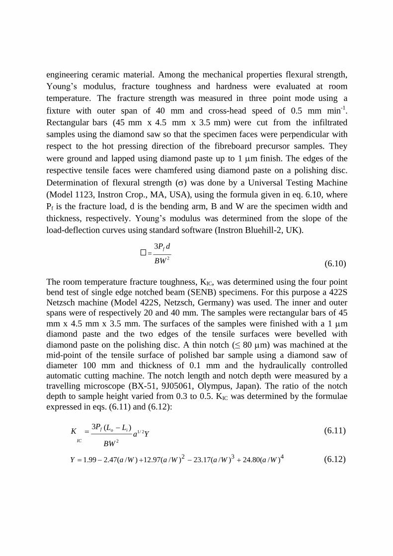
engineering ceramic material. Among the mechanical properties flexural strength,
Young‟s modulus, fracture toughness and hardness were evaluated at room
temperature. The fracture strength was measured in three point mode using a
fixture with outer span of 40 mm and cross-head speed of 0.5 mm min-1.
Rectangular bars (45 mm x 4.5 mm x 3.5 mm) were cut from the infiltrated
samples using the diamond saw so that the specimen faces were perpendicular with
respect to the hot pressing direction of the fibreboard precursor samples. They
were ground and lapped using diamond paste up to 1 m finish. The edges of the
respective tensile faces were chamfered using diamond paste on a polishing disc.
Determination of flexural strength () was done by a Universal Testing Machine
(Model 1123, Instron Crop., MA, USA), using the formula given in eq. 6.10, where
Pf is the fracture load, d is the bending arm, B and W are the specimen width and
thickness, respectively. Young‟s modulus was determined from the slope of the
load-deflection curves using standard software (Instron Bluehill-2, UK).
3Pf d
BW 2
(6.10)
The room temperature fracture toughness, KIC, was determined using the four point
bend test of single edge notched beam (SENB) specimens. For this purpose a 422S
Netzsch machine (Model 422S, Netzsch, Germany) was used. The inner and outer
spans were of respectively 20 and 40 mm. The samples were rectangular bars of 45
mm x 4.5 mm x 3.5 mm. The surfaces of the samples were finished with a 1 m
diamond paste and the two edges of the tensile surfaces were bevelled with
diamond paste on the polishing disc. A thin notch (≤ 80 m) was machined at the
mid-point of the tensile surface of polished bar sample using a diamond saw of
diameter 100 mm and thickness of 0.1 mm and the hydraulically controlled
automatic cutting machine. The notch length and notch depth were measured by a
travelling microscope (BX-51, 9J05061, Olympus, Japan). The ratio of the notch
depth to sample height varied from 0.3 to 0.5. KIC was determined by the formulae
expressed in eqs. (6.11) and (6.12):
3Pf K (Lo Li )
a1/ 2Y (6.11) IC
BW 2
Y 1.99 2.47(a /W ) 12.97(a /W )2 23.17(a /W )
3 24.80(a /W )
4 (6.12)

f
where Lo, Li are the outer and inner span, B is the specimen width, W is the
specimen height, Pf is the fracture load and a is the notch depth.
The room temperature flexural strength, Young‟s modulus and fracture toughness
of the SiC ceramic composite are presented in table 6.7. In the present study the
recorded average values of strength, Young‟s modulus and fracture toughness were
126 MPa, 161 GPa and 2.6 MPa√m, respectively. The scatters obtained in the
mechanical property data were related to the flaws present in the test specimen.
6.3.4.2 Assessment of reliability of room temperature strength
The reliability of the strength data was assessed by measuring the Weibull
modulus. In brittle solids the fracture strength is statistical in nature and depends
Table 6.7 Room temperature mechanical properties of SiC ceramic composite
samples synthesized from coir fibreboard bio-precursors.
Flexural strength (MPa) Young‟s modulus (GPa) Fracture toughness (MPa√m)
126.16±14.53 160.92±5.28 2.62±0.24
on the probability of the presence of flaw that is capable of initiating fracture at a specified applied stress. This is the main reason behind the scatter or distribution of
strength. In the Weibull approach, the failure of probability (Pf) is given by the
following equation:
P 1 exp[( )
m
]
0
(6.12)
`
where, is the flexural strength, 0 is the characteristic strength and m is a
constant related to the homogeneity of the material. This constant (m) is called the
Weibull modulus which represents the measure of the scatter of the particular mechanical property (strength). The mathematical form of the two-parameter Weibull equation is as follows:
ln ln{1/(1 Pf )} m ln const. (6.13)

If ln ln {1/(1- Pf)} is plotted against ln , the curve will be a straight line, the slope
of which will be the value of m. From the set of strength data, the probability, Pf,
was calculated as n/(N+1), where n is the order number and N is the total number
of specimen. ln ln [1/(1- Pf)] was plotted against ln , and a least square
examination of the slope of the ordered strength measurement gives the values of Weibull modulus, m. The plot the fracture strength data of the SiC ceramic composite sample made from the coir fibreboard bio-precursor on a standard
Weibull format is shown in Fig. 6.10 The Weibull modulus, which is the slope of the least square fitted line, was found to be 8.13. The Weibull modulus indicated that distribution of flaws was not very uniform in the samples.
A failure analysis was done in order to understand the sources of flaws that were
responsible for failure during strength testing. For this purpose the failed
specimens of the room temperature fracture strength test were subjected to
fractographic examination by scanning electron microscopy. The strength limiting
flaws common to the failed specimens included pores, cracks, large grains and
occasional surface preparation flaws. Porous zones were of different shapes and
MPa
100 120 140 160 180 2
1
0
-1
-2
-3
-4 4.6 4.7 4.8 4.9 5.0 5.1 5.2
ln()
Fig. 6.10. Weibull plot of flexural strength of the biomorphic SiC ceramics
synthesized from coir fibreboard.
sizes and they were found to be present either at the surface or distributed within
the volume of the samples. Clusters of small pores with sizes ranging from 10 to
lnln
(1/(
1-P
))
f
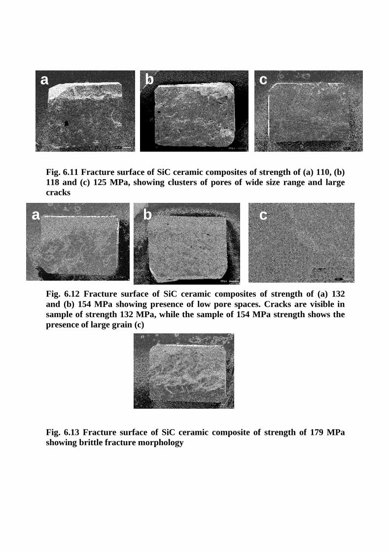
Fig. 6.11 Fracture surface of SiC ceramic composites of strength of (a) 110, (b)
118 and (c) 125 MPa, showing clusters of pores of wide size range and large
cracks
Fig. 6.12 Fracture surface of SiC ceramic composites of strength of (a) 132
and (b) 154 MPa showing presence of low pore spaces. Cracks are visible in
sample of strength 132 MPa, while the sample of 154 MPa strength shows the
presence of large grain (c)
Fig. 6.13 Fracture surface of SiC ceramic composite of strength of 179 MPa
showing brittle fracture morphology
c b a
c b a
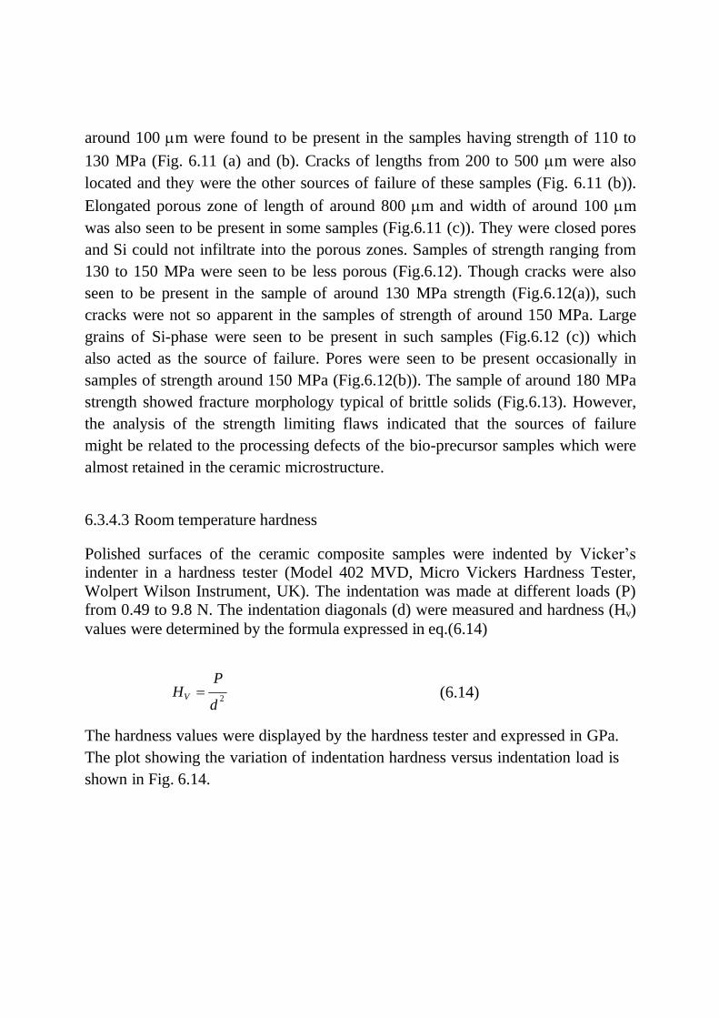
around 100 m were found to be present in the samples having strength of 110 to
130 MPa (Fig. 6.11 (a) and (b). Cracks of lengths from 200 to 500 m were also
located and they were the other sources of failure of these samples (Fig. 6.11 (b)).
Elongated porous zone of length of around 800 m and width of around 100 m
was also seen to be present in some samples (Fig.6.11 (c)). They were closed pores
and Si could not infiltrate into the porous zones. Samples of strength ranging from
130 to 150 MPa were seen to be less porous (Fig.6.12). Though cracks were also
seen to be present in the sample of around 130 MPa strength (Fig.6.12(a)), such
cracks were not so apparent in the samples of strength of around 150 MPa. Large
grains of Si-phase were seen to be present in such samples (Fig.6.12 (c)) which
also acted as the source of failure. Pores were seen to be present occasionally in
samples of strength around 150 MPa (Fig.6.12(b)). The sample of around 180 MPa
strength showed fracture morphology typical of brittle solids (Fig.6.13). However,
the analysis of the strength limiting flaws indicated that the sources of failure
might be related to the processing defects of the bio-precursor samples which were
almost retained in the ceramic microstructure.
6.3.4.3 Room temperature hardness
Polished surfaces of the ceramic composite samples were indented by Vicker‟s indenter in a hardness tester (Model 402 MVD, Micro Vickers Hardness Tester,
Wolpert Wilson Instrument, UK). The indentation was made at different loads (P) from 0.49 to 9.8 N. The indentation diagonals (d) were measured and hardness (Hv)
values were determined by the formula expressed in eq.(6.14)
P HV
2
d (6.14)
The hardness values were displayed by the hardness tester and expressed in GPa.
The plot showing the variation of indentation hardness versus indentation load is
shown in Fig. 6.14.

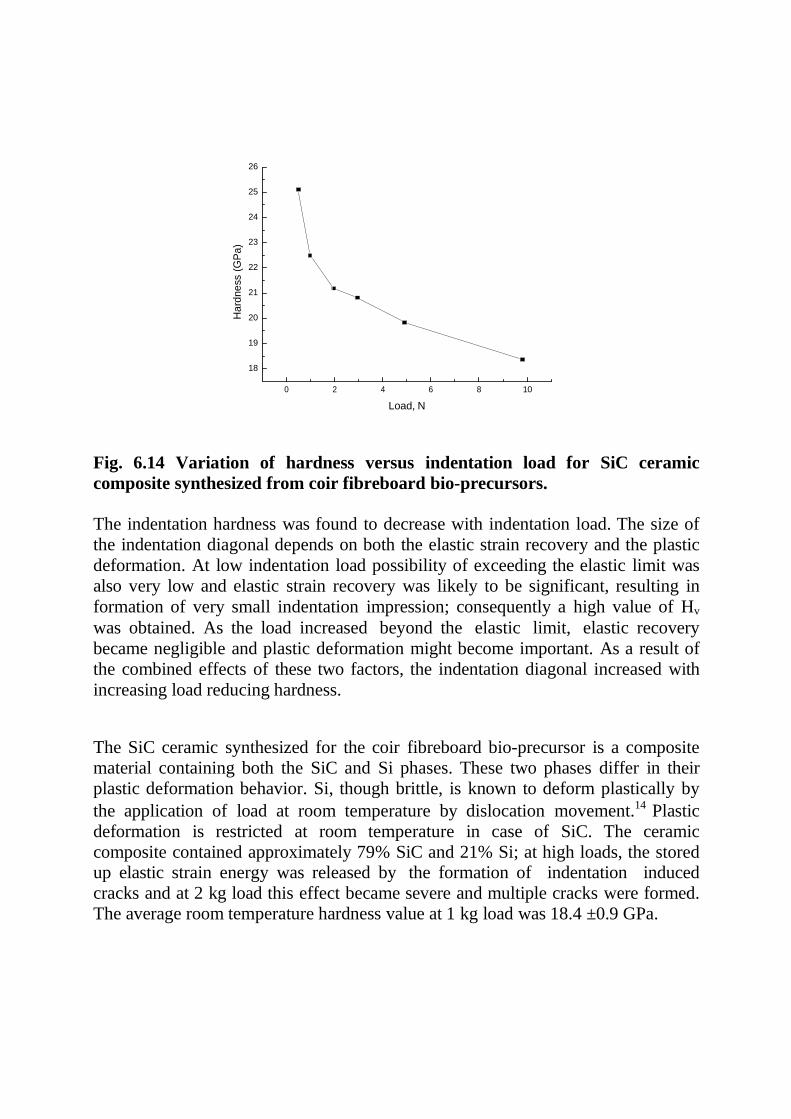
26
25
24
23
22
21
20
19
18
0 2 4 6 8 10
Load, N
Fig. 6.14 Variation of hardness versus indentation load for SiC ceramic
composite synthesized from coir fibreboard bio-precursors.
The indentation hardness was found to decrease with indentation load. The size of
the indentation diagonal depends on both the elastic strain recovery and the plastic
deformation. At low indentation load possibility of exceeding the elastic limit was
also very low and elastic strain recovery was likely to be significant, resulting in
formation of very small indentation impression; consequently a high value of Hv
was obtained. As the load increased beyond the elastic limit, elastic recovery
became negligible and plastic deformation might become important. As a result of
the combined effects of these two factors, the indentation diagonal increased with
increasing load reducing hardness.
The SiC ceramic synthesized for the coir fibreboard bio-precursor is a composite
material containing both the SiC and Si phases. These two phases differ in their
plastic deformation behavior. Si, though brittle, is known to deform plastically by
the application of load at room temperature by dislocation movement.14 Plastic
deformation is restricted at room temperature in case of SiC. The ceramic
composite contained approximately 79% SiC and 21% Si; at high loads, the stored up elastic strain energy was released by the formation of indentation induced
cracks and at 2 kg load this effect became severe and multiple cracks were formed.
The average room temperature hardness value at 1 kg load was 18.4 ±0.9 GPa.
Ha
rdn
ess (
GP
a)
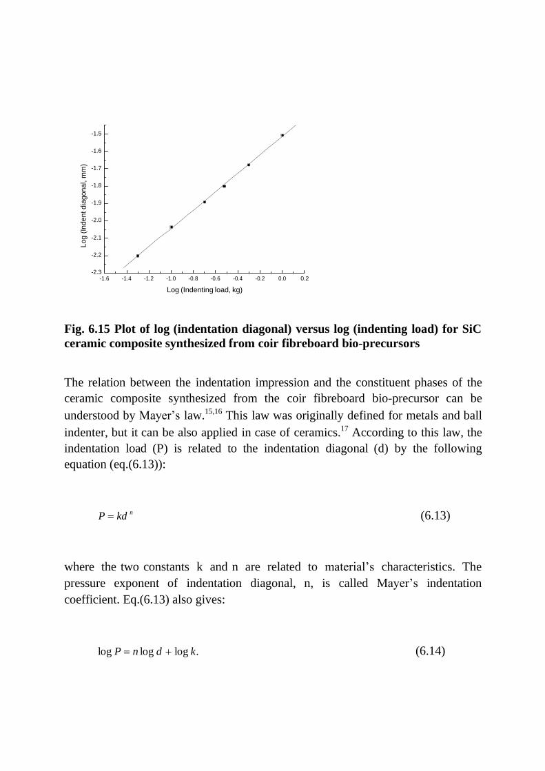
-1.5
-1.6
-1.7
-1.8
-1.9
-2.0
-2.1
-2.2
-2.3 -1.6 -1.4 -1.2 -1.0 -0.8 -0.6 -0.4 -0.2 0.0 0.2
Log (Indenting load, kg)
Fig. 6.15 Plot of log (indentation diagonal) versus log (indenting load) for SiC
ceramic composite synthesized from coir fibreboard bio-precursors
The relation between the indentation impression and the constituent phases of the
ceramic composite synthesized from the coir fibreboard bio-precursor can be
understood by Mayer‟s law.15,16 This law was originally defined for metals and ball
indenter, but it can be also applied in case of ceramics.17 According to this law, the
indentation load (P) is related to the indentation diagonal (d) by the following
equation (eq.(6.13)):
P kd n (6.13)
where the two constants k and n are related to material‟s characteristics. The
pressure exponent of indentation diagonal, n, is called Mayer‟s indentation
coefficient. Eq.(6.13) also gives:
log P n log d log k. (6.14)
Lo
g (
Ind
en
t d
iag
on
al, m
m)
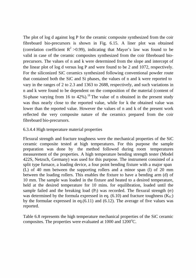
The plot of log d against log P for the ceramic composite synthesized from the coir
fibreboard bio-precursors is shown in Fig. 6.15. A liner plot was obtained
(correlation coefficient R2
>0.99), indicating that Mayer‟s law was found to be
valid in case of the ceramic composites synthesized from the coir fibreboard bio-
precursors. The values of n and k were determined from the slope and intercept of
the linear plot of log d versus log P and were found to be 2 and 1072, respectively.
For the siliconized SiC ceramics synthesized following conventional powder route
that contained both the SiC and Si phases, the values of n and k were reported to
vary in the ranges of 2 to 2.3 and 1363 to 2688, respectively, and such variations in
n and k were found to be dependent on the composition of the material (content of
Si-phase varying from 16 to 42%).18 The value of n obtained in the present study
was thus nearly close to the reported value, while for k the obtained value was
lower than the reported value. However the values of n and k of the present work
reflected the very composite nature of the ceramics prepared from the coir
fibreboard bio-precursors.
6.3.4.4 High temperature material properties
Flexural strength and fracture toughness were the mechanical properties of the SiC
ceramic composite tested at high temperatures. For this purpose the sample
preparation was done by the method followed during room temperatures
measurement of the properties. A high temperature bending strength tester (Model
422S, Netzsch, Germany) was used for this purpose. The instrument consisted of a
split type furnace, a loading device, a four point bending fixture with a major span
(L) of 40 mm between the supporting rollers and a minor span (l) of 20 mm
between the loading rollers. This enables the fixture to have a bending arm (d) of
10 mm. The sample was loaded in the fixture and heated to a desired temperature,
held at the desired temperature for 10 mins. for equilibration, loaded until the
sample failed and the breaking load (Pf) was recorded. The flexural strength ()
was determined by the formula expressed in eq. (6.10) and fracture toughness (KIC)
by the formulae expressed in eq.(6.11) and (6.12). The average of five values was
reported.
Table 6.8 represents the high temperature mechanical properties of the SiC ceramic
composites. The properties were evaluated at 1000 and 1200oC.

Table 6.8 High temperature mechanical properties of SiC ceramic composite
samples synthesized from coir fibreboard bio-precursors
Flexural strength (MPa) Fracture toughness (MPa√m
1000oC 1200
oC 1200
oC
135.75±19.08 173.83±17.06 3.70±0.22
The SiC ceramic composite materials showed an increase in flexural strength of up
to 1200oC. The increase in strength with temperature may be attributed to the
healing of crack tip owing to oxidation.19-22
The SiC ceramic composite also
showed an increase in fracture toughness at 1200oC. At elevated temperature an
increasing amount of plasticity may be expected in Si.23 This fact coupled with the possibility of crack healing as a result of oxidation likely made the notched bars stronger at high temperatures and the fracture toughness was increased. Increase in flexural strength and fracture toughness with temperature was observed in case of
siliconized SiC ceramics, the duplex composites containing SiC and Si phases.24
The results on high temperature mechanical properties of SiC ceramic composites of the present work are thus similar to the published data.
6.3.5 Oxidation behaviour of SiC ceramic composites
Oxidation plays a dominant role in influencing the mechanical properties of the
ceramic composites. It is therefore very much pertinent to study the oxidation
behavior of the ceramic composites synthesized from the coir fibreboard bio-
precursors.
Oxidation behavior was studied by thermogravimetric method (STA 409C, Netzsch-Geratebau, GmbH, Germany) in flowing dry air (P=100 kPa, flow rate =
1L/h) at different temperature from 1200 to 1350oC. Rectangular polished chips (10 mm x 10mm x 3 mm) were used for this purpose. They were heated at a
constant rate (20 K min-1
) and an isothermal hold was given for a period of 5 h at the peak temperatures and the mass variation (% mass retained) was automatically recorded as a function of time.
The weight gain recorded was converted to weight gain per unit area and was
plotted as a function of time. The plots are shown in Fig.6.16. For the entire period
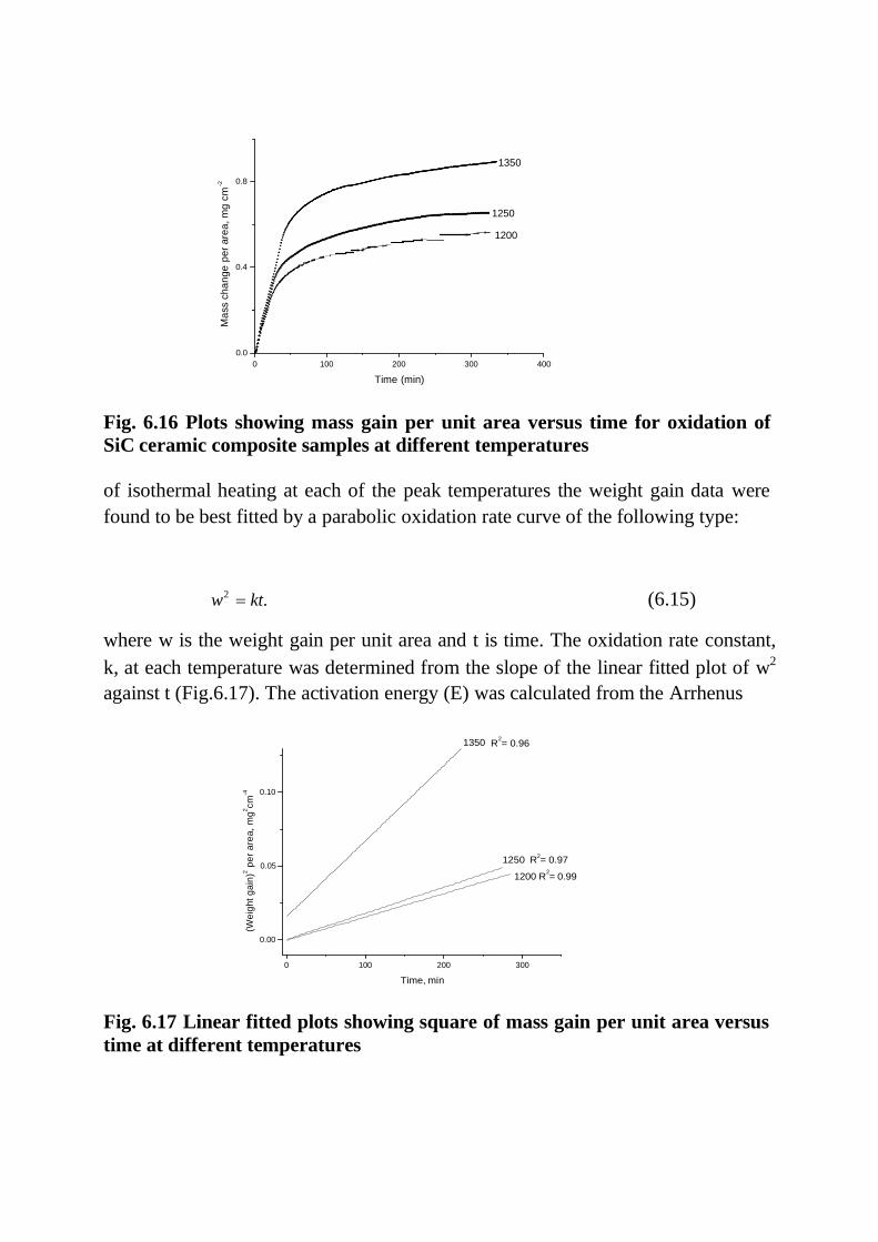
0.8
0.4
0.0
0 100 200 300 400
Time (min)
Fig. 6.16 Plots showing mass gain per unit area versus time for oxidation of
SiC ceramic composite samples at different temperatures
of isothermal heating at each of the peak temperatures the weight gain data were
found to be best fitted by a parabolic oxidation rate curve of the following type:
w2 kt. (6.15)
where w is the weight gain per unit area and t is time. The oxidation rate constant,
k, at each temperature was determined from the slope of the linear fitted plot of w2
against t (Fig.6.17). The activation energy (E) was calculated from the Arrhenus
1350 R
2= 0.96
0.10
0.05 1250 R
2= 0.97
1200 R2= 0.99
0.00
0 100 200 300
Time, min
Fig. 6.17 Linear fitted plots showing square of mass gain per unit area versus
time at different temperatures
1350
1250
1200
-2
Ma
ss c
ha
ng
e p
er
are
a, m
g c
m
(Weig
ht
ga
in)2
pe
r a
rea,
mg
2cm
-4

equation: k =Ae-E/RT
, where E is the pre-exponential factor independent of
temperature, E is the activation energy and T is the absolute temperature. The
Arrhenus plot of log k versus 1/T is shown in Fig. 6.18. Al the points
corresponding to the test temperatures fit to a straight line where the gradient of the
line gives the value of activation energy. The value o E obtained in the present
study was 163.4 kJ mol-1 (38.91 kcal mol-1).
-3.2
-3.4
-3.6
-3.8
6.3 6.6 6.9
1/T * 10^4
Fig. 6.18 Arrhenus plot of log k versus 1/T
In case of oxidation of Si it is widely accepted that the process of oxidation is
controlled by diffusion of diatomic oxygen through the growing silica film.25 The
activation energy of Si agrees well with the value of activation energy of 112.5 kJ
mol-1 for molecular diffusion of oxygen through fused silica.26 The reported values
of activation energy of SiC (sintered and hot-pressed SiC) at low temperatures
were from 133.5 to 154.4 kJ mol-1, whereas at high temperature higher values were
obtained.27,28 This suggests that inward diffusion of oxygen molecules may be
responsible for oxidation of SiC at low temperatures, similar to the process
occurring in the case of silicon. But at high temperatures, high activation energy
indicates that oxygen transport mechanism is most unlikely, and alternatively, it
has been concluded that outward desportion of CO(g) molecules from SiC/SiO2
interface is the rate controlling process. The ceramic composite material of the
R2= 0.85
Log
k

present work was duplex in nature containing both the SiC and Si phases and the
measured value of activation energy of 163.4 kJ mol-1
suggests that both SiC and
Si oxidized and the oxidation process occurred by the inward oxygen transport
mechanism.
6.3.6 Comparison of properties of SiC ceramic composites synthesized from coir
fibreboard bio-precursors and ceramic powder preforms
SiC ceramic composites containing SiC and Si phases are conventionally prepared
using ceramic powder preforms and they are popularly known as reaction bonded
silicon carbide (RBSC) or reaction sintered SiC (RSSC) or siliconized SiC
ceramics. The materials were originally developed in early sixties of the last
century and the LSI technique was first applied to prepare these materials.29 A
comparison of the properties of the SiC ceramic composites synthesized the coir
fibreboard bio-precursor and the RBSC will therefore be useful and appropriate.
The conventionally prepared materials were mostly very dense containing negligible amount of porosity. The materials prepared by the Reactor Fuel Element Laboratory, United Kingdom Atomic Energy Authority (UKAEA), Springfields,
UK, under the brand name of REFEL, had 8-10 % v/v Si phase.30-32 The same materials prepared by the Coors porcelain Co., USA, and the Norton Co., USA,
contained 10-12 % Si-phase.33,34 The materials prepared by Hillig et al. by reactive infiltration of Si melt into densely packed carbon fibre preforms contained some
amount of porosity and showed a wide variation of Si phase (15-50% v/v).35,36
Chakrabarti et al. prepared the RBSC materials using ceramic powder preforms that also exhibited negligible amount of porosity, but wide variation of Si-phase in
a range of 11-47% v/v.24 The SiC ceramic composite materials prepared from the coir fibreboard bio-precursors had around 12 % porosity and 23% v/v Si-phase. Compared to the technically manufactured products (like RBSC), presence of higher amount of porosity in the bio-precursor derived ceramic composites might be related to processing defects incorporated during the green fabrication of bio- precursor specimens. The reported room temperature strength of the
conventionally prepared material varied widely from 146 to 485 MPa.30-36 The material prepared by Chakrabarti et al. also showed strength variation from around
190 to 230 MPa.24
The strength of the duplex SiSiC ceramic composites depends on many factors, such as, starting SiC particle size, content of Si-phase, bending mode, span length of the test fixture, test temperature, atmosphere, etc. In most of the reported studies, the span length was from 16 to 18 mm; in the cases where higher span length ( ~ 38 mm) was used a low strength value of 146 MPa was obtained for the SiC ceramic composite containing ~ 10% Si-phase. In the present


work the recorded value of the room temperature flexural strength was around 126 MPa (obtained with a span length of 40 mm) for the ceramic composite. The strength of the duplex ceramic composite containing SiC and Si phases, decreases
with increase of the content of Si-phase.24 Also the strength decreases with
increase in porosity.37 Thus the strength value of 126 MPa obtained (when tested with a span length of 40 mm) for the coir fibreboard bio-precursor based SiC ceramic composites containing ~12 % porosity and ~23 % Si-phase, was no less significant and was comparable with the strength values of the conventionally prepared materials. Conventional materials exhibit increase in strength at high temperatures; increase in strength reported by many authors was from around 5 to
25% for increase of temperature up to around 1200oC.
30-36 For the reaction bonded
SiC ceramic composites prepared by Chakrabarti et al. using ceramic powder
preforms, an increase in strength of around 18% was obtained.24 In the present work the coir fibreboard bio-precursor derived SiC ceramic composite exhibited
around 38% increase in flexural strength up to 1200oC, indicating that the high
temperature strength of the materials was comparable to that of the conventional materials. Like flexural strength, the room temperature fracture toughness (KIC) of
the SiC ceramic composites synthesized from the coir fibreboard bio-precursors and the reaction bonded SiC ceramic composites conventionally prepared from the ceramic powder preforms can be compared. Carrol et al. showed that the room temperature KIC of the conventionally prepared RBSC were in the range of 2.95 to 3.73 MPa√m;38 for the same materials Chakrabarti et al. obtained the room
temperature fracture toughness from 2.7 to 3.73 MPa√m.24 The room temperature KIC value of 2.62 MPa√m of the SiC ceramic composites synthesized from the coir fibreboard bio-precursors was thus nearly comparable with the reported data. The
recorded increase in KIC up to 1200oC for the bio-precursor derived ceramic composites was around 41% and the increment was comparable with the reported
increase in KIC for the conventionally prepared materials.24,38
The studies on hardness of conventionally prepared duplex SiSiC ceramic composites are very limited. Forrest et al. examined the microhardnes of the reaction bonded SiC ceramics conventionally prepared from ceramic powder
performs and reported a room temperature hardness value of 25.7 GPa at 0.1 kg.30
the RBSC material prepared by Chakrabarti et al. exhibited a room temperature
hardness of 21.4 GPa at 1.0 kg load.39 In the present work the SiC ceramic composites synthesized from the coir fibreboard bio-precursors exhibited an average hardness of 18.4 GPa at 1.0 kg load at room temperature. Though the bio- precursor derived ceramic composites exhibited a slightly lower hardness value than their conventional counterparts prepared from the ceramic powder preforms,
the experimentally measured hardness value of 18.4 GPa was no less significant,
because the bio-precursor derived ceramic materials contained around 12 %
porosity, when their conventional counterparts were absolutely dense materials
with negligible porosity present in them.
The SiC ceramic composites synthesized from the coir fibreboard bio-precursors
exhibited adequate oxidation resistance because of the formation of the protective
silica scale; the resistance to oxidation was related to the diffusive transport of
molecular oxygen through the silica layer, a mechanism also responsible oxidation
resistance of conventionally prepared SiSiC ceramic composites.
The mechanical properties like flexural strength, Young‟s modulus and fracture
toughness are considered important for assessment of the application possibilities
of ceramic materials in advanced engineering areas. The mechanical properties of
the SiC ceramic composites synthesized from the coir fibreboard bio-precursors
and other plant precursors (woods and processed precursors of woody materials)
can also be compared. The mechanical property data of the SiC ceramics prepared
from natural and processed precursors, as investigated and reported by many
researchers, are summarized in table 6.9. Difference in materials properties of the
ceramics and the test procedures are likely to be the reasons for the wide variation
of mechanical properties recorded in these investigations. The biomorphic SiC
ceramics synthesized from artificial precursors (wood powder compacts, medium
density fibreboards (MDF), papers, cotton linters, cotton fibres, etc.) exhibited
fracture strength, Young‟s modulus and fracture toughness in the ranges of 135 to
450 MPa, 330 to 364 GPa and 0.97 to 4.10 MPa√m respectively. The reported
variations of these properties for the ceramics synthesized from the natural
precursors were in the ranges of 130 to 333 MPa, 165 to 450 GPa and 1.65 to 3.40
MP√m respectively. The mechanical property data of the SiC ceramic composites
synthesized from the coir fibreboard bio-precursors are thus within the ranges of
the mechanical properties reported for the ceramics made from the natural and the
artificial precursors.
Comparison of property data of the coir fibreboard derived ceramic composites and
their conventionally prepared counterparts, thus, indicates the suitability of the
former materials for application as engineering ceramics. The conventional
materials (duplex ceramic composites containing SiC and Si phases, like RBSC,
RSSC, SiSiC, etc.), find applications as structural ceramics in many advanced
engineering areas, for example, cladding elements for nuclear reactor fuel, burner
nozzles, spraying nozzles, rocket nozzles, ceramic heat exchangers, recuperators
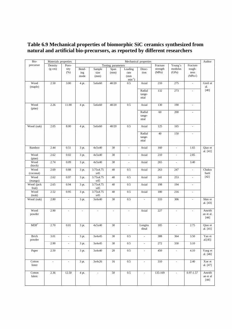
Table 6.9 Mechanical properties of biomorphic SiC ceramics synthesized from
natural and artificial bio-precursors, as reported by different researchers
Bio-
precursor
Materials properties Mechanical properties Author
Density
(g cm)
Poro-
sity
(%)
Testing parameters Fracture
strength
(MPa)
Young‟s
modulus
(GPa)
Fracture
tough-
ness
(MPa√)
Bend-
ing
mode
Sample
size
(mm)
Span
(mm)
Loading
rate
(mm
min-1
)
Direc-
tion
Wood
(maple)
2.50 3.00 4 pt. 5x6x60 40/20 0.5 Axial 210 275 - Greil et
al.
[40] Radial
tange-
ntial
132 273 -
Wood
(pine)
2.26 11.00 4 pt. 5x6x60 40/20 0.5 Axial 130 190 -
Radial
tange-
ntial
60 200 -
Wood (oak) 2.05 8.00 4 pt. 5x6x60 40/20 0.5 Axial 125 165 -
Radial
tange-
ntial
40 150 -
Bamboo 2.44 0.51 3 pt. 4x5x40 30 - Axial 160 - 1.65 Qiao et
al. [41]
Wood
(pine)
2.62 0.02 3 pt. 4x5x40 30 - Axial 210 - 2.85
Wood
(birch)
2.74 0.09 3 pt. 4x5x40 30 - Axial 265 - 3.40
Wood
(coconut)
2.69 0.88 3 pt. 3.75x4.75
x45
40 0.5 Axial 263 247 - Chakra
barti
[42] Wood
(mango)
2.62 0.97 3 pt. 3.75x4.75
x45
40 0.5 Axial 241 253 -
Wood (jack
fruit)
2.65 0.94 3 pt. 3.75x4.75
x45
40 0.5 Axial 198 194 -
Wood
(teak)
2.52 0.95 3 pt. 3.75x4.75
x45
40 0.5 Axial 180 216 -
Wood (oak) 2.80 - 3 pt. 3x4x40 30 0.5 - 333 306 - Shin et
al. [43]
Wood
powder
2.90 - - - - - Axial 227 - - Amrith
an et al.
[44]
MDF*
2.70 0.01 3 pt. 4x5x40 30 - Longitu
dinal
185 - 2.75 Qiao et
al. [41]
Brich
powder
3.01 - 3 pt. 3x4x45 30 0.5 - 388 364 3.50 Yan et
al.[45]
2.90 - 3 pt. 3x4x45 30 0.5 - 272 330 3.10
Paper 2.50 - 3 pt. 3x4x40 20 0.5 - 450 - 4.10 Yang et
al. [46]
Cotton
linter
- - 3 pt. 3x4x26 16 0.5 - 310 - 2.40 Xue et
al. [47]
Cotton
fabric
2.36 12.50 4 pt. - 50 0.5 - 135-169 - 0.97-1.57 Amrith
an et al
[44]
for waste heat recovery, mechanical pump seals, kiln furniture, etc. Many of these
application conditions involve high temperatures and hostile atmospheres.
However, the properties (density, porosity, microstructure, phase compositions,
flexural strength, Young‟s modulus, fracture toughness, hardness and oxidation
behavior) of the SiC ceramic composites synthesized from the coir fibreboard
precursors indicate their strong application possibilities as ceramic kiln furniture.
6.3.7 Examination of application possibility of SiC ceramic composites
synthesized from coir fibreboard bio-precursors
In the present project the SiC ceramic composites synthesized from coir fibreboard
was tested as the support structures (kiln furniture) suitable for calcinations/heat
treatment of charges/ceramic bodies.
The SiC ceramic composites synthesized from the coir fibreboard bio-precursors in
the form of a rectangular plate were used for this purpose. The plate was used as a
support plate for resting ceramic crucibles inside a furnace or kiln. The powders that were to be heated were taken in the crucible and the crucible was kept on the
rectangular plate. The crucible together with the support plate was heated up to
1300oC and kept at the temperature for 24 h in a muffle furnace. After the heating
was over the condition of the plate was examined. No distortion, disintegration or
sagging was noticed. This indicated that the SiC ceramic composites made from
the coir fibreboard bio-precursors are suitable for use as kiln furniture for firing of ceramic wares.
References
1. R. Pampuch, J. Bialoskorski and E. Walasek, “Mechanism of reactions in the
Si+Cf system and the self-propagating high-temperature synthesis of silicon
carbide,” Ceram. Int. 13(1), 63-8 (1987).
2. R. Pampuch, J. Bialoskorski and E. Walasek, “Reaction mechanism in carbon-
liquid silicon systems at elevated temperatures”, Ceram. Int. 12, 99-106 (1986).
3. M. Pyzalski, J. Bialoskorski and E. Walasek, “Reaction between carbon fibres
and molten silicon: heat determination using DTA”, J. Thermal. Anal. 31 1193-
1196 (1986).
4. E. Schonberger and J. Heinrich, “Differential thermoanalytical investigation of
the reaction of carbon with silicon to silicon carbide”, Ceramic Forum Intl. 70[4]
161-164 (1993).
5. E. Fitzer and R. Gadow “Fiber reinforced silicon carbide,” Am. Ceram. Soc.
Bull. 65(2) 326-35 (1986)
6. T. J Whalen and A. T. Anderson, “Wetting of SiC, Si3N4 and carbon by Si and
binary Si alloys,” J. Am. Ceram. Soc. 58(9-10) 396-9 (1975)
7. P. Greil, T. Lifka and A. Kaindl, “Biomorphic cellular silicon carbide ceramics
from wood: I. processing and microstructure,” J. Eur. Ceram. Soc. 18(14) 1961-73
(1998)
8. W. Washburn, “The dynamics of capillary flow,” Phys Rev 17(3) 273-83 (1921)
9. L. Battezzati and A. L. Greer, “The viscosity of liquid metals and alloys,” Acta.
Metall. 37(7) 1791-802 (1989)
10. S. C. Hardy, “The surface tension of liquid silicon,” J. Cryst. Growth, 69(2-3)
456-60 (1984)
11. O. P. Chakrabarti, D. Mallick, H. S. Maiti and R. Majumdar "Microcellular
Si/SiC ceramics by replication of Indian dicotyledonous woods" Trans. Ind.
Ceram. Soc., 65[1], 23-8 (2006)
12. Y. M. Chiang, R. P. Messner and C. D. Terwilliger, “Reaction formed silicon
carbide,” Mater. Sci. Eng. A, 114, 63-74 (1991)
13. C. Zollfrank and H. Sieber, “Microstructure Evolution and Reaction
Mechanism of Biomorphous SiSiC Ceramics,” J. Am. Ceram. Soc., 88, 51-8
(2005)
14. M.M.Mystyaev, V.I.Nitenko and V.I. Nesterenko, “Dislocation structure and
microscopic characteristics of plastic deformation at creep of silicon crystal”, Sov.
Sol. State Phys., 36[1]86-96 (1969)

15. E. Meyer, “Studies on hardness testing and hardness”, Z.Ver. German. Ing.
52[17]645-654 (1908)
16. D.Tabor, “The Hardness of solids”, in „Surface Physics‟, Cavendish
Laboratory, Cambridge, Vol.1, Part 1, U.K., 145-79, 1970
17. O.P.Chakrabarti, “Reaction sintering of SiC”, Ph.D. Dissertation, University of
Calcutta, Kolkata, India, 2000.
18. O.P.Chakrabarti, P.K.Das and J.Mukerji, “Influence of free silicon content on
the microhardness of reaction bonded silicon carbide”, Ceramics Forum
International, 74[2], 98-101, (1997).
19. D.E. Schwab and M.M.Kotchik, “High temperature strength of -SiC in slat
and oxidizing atmosphere”, Am. Ceram. Soc. Bull.,59[8],805-813 (1980)
20. F.F.Lange, “Healing of surface cracks in SiC by oxidation”, J. Am. Ceram.
Soc., 53[5], 290 (1970)
21. T.E.Easler, R.C.Bradt and R.E. Tressler, “Strength distribution of SiC ceramics
after oxidation and oxidation under load”, J. Am. Ceram. Soc., 64[12], 731-34
(1981)
22. W.J. Tomlinson and D.M. Caslin, “Strength of SiC and SiC-7.5%vol. TiBr2
composite after corrosion with Na2SO4 and NaCl deposits”, Ceram. Intl., 17[1]61- 66 (1991)
23. G.L. Pearson, W.T.Read, Jr. and W.L. Fledman, “ Deformation and fracture of
small Si crystal”, Acta. Metall., 5[4], 181-191 (1957)
24. O.P.Chakrabarti, J. Mukerji and S.Ghosh, “ Influence of grain size, free silicon
content and temperature on the strength and toughness of reaction sintered silicon
carbide”, Ceram. Intl., 20[2], 283-286, (1994)
25. M.A. Hopper, R.A. Clarke and L.Young, “Thermal oxidation of Si - in situ
measurement of growth rate using ellipsometry”, J.Electrochem. Soc., 122[9],
1216-1222(1975)
26. F.J. Norton, “Permeation of gaseous oxygen through vitreous silica”, Nature,
191(4789),701 (1961)

27. S.C.Singhal, “Oxidation kinetics of hot-pressed silicon carbide”, J.Mater.Sci.,
11[7], 1246-53 (1976)
28. J.A.Castelo and R.E.Tressler, ”Oxidation kinetics of hot-pressed and sintered
-SiC “, J.Am.Ceram.Soc., 64[6]327-331 (1981)
29. P. Popper, „The preparation of self-bonded silicon carbide, in Special
Ceramics, Edited by P. Popper, British Ceramics Research Association, London,
U.K., 209-219 (1960)
30. C.W. Forrest, P. Kennedy and J.V. Shennan, “The fabrication and properties of
self bonded silicon carbide”, in Special Ceramics, Vol.5, British Ceramics
Research Association, London, U.K., 99-123 (1972)
31. J.R. McLaren, G.Tappin and R.W. Davidge, “The relationship between
temperature and environment, texture and strength of self-bonded silicon carbide”,
Proc. Brit. Ceram. Soc., 20, 259-274 (1972)
32. P. Kennedy, J.V. Shennan, P. Brainden, J. McLaren and R. Davidge, “An
assessment of performance of REFEL silicon carbide under the conditions of
thermal stress”, in „Ceramics for turbine and other high temperature applications‟,
Ed. D.J. Godfrey, Brit. Ceram. Soc., 22, 76-87 (1973)
33. J.C. Larsen and J.W. Adams, “Property screening and evaluation of ceramic
materials”, Final Report # AFWAL-83-4141, IIT Research Institute for Air Force
Wright Aeronautical Laboratories, Materials Laboratories, Chicago, Illinois, USA,
1984
34. M. Coombs, D. Kotchick and M. Weidhass, “High temperature ceramic heat
exchanger development”, Electric Power Research institute, Final Report # EPRI-
AP-3019, Palo Alto, CA, USA, 1983
35. W.B. Hillig, R.L. Mehan, C.R. Morelock, V.J. DeCarlo and W. Laskaw, “
Silicon/silicon carbide composite”, Am. Ceram. Soc. Bull., 54[12], 1054-1056
(1975)
36. W.B.Hillig, “Tailoring of Si/SiC composites for turbine applications”, in
„Ceramic for high performance applications-II‟, Ed. J.J.Bruke, E.N.Lone and
R.N.Katz, Brook Hill Publishing Co., Massachusetts, USA, 989-1000, 1978

37. R. W. Rice, “Extension of the exponential porosity dependence of strength and
elastic moduli,” J. Am. Ceram. Soc., 59, 536–537 (1976)
38. D.F.Carroll, R.E.Tressler, Y.Tsai and C.Near, “High temperature mechanical
properties of siliconized silicon carbide composites”, in „Tailoring multiphase and
composite ceramics‟, vol.20, Ed. R.E.Tressler, G.L.Missing, C.G.Pantano and
R.E.Newnhan, Plenum Press, New York, USA, pp. 775-788, 1985
39. O.P.Chakrabarti, P.K.Das and J.Mukerji, “Influence of free silicon content on
the microhardness of reaction bonded silicon carbide”, Ceram. Forum Intl.,
74[2]98-101( 1997)
40. P. Greil, T. Lifka, A. Kaindl, “ Biomorphic cellular silicon carbide ceramics
from wood: II. Mechanical properties”, J. Eur. Ceram. Soc. 18, 1975-83 (1998)
41. G. Qiao, R. Ma, N. Cai, C. Zhang, Z. Jin, “Mechanical properties and
microstructure of Si/SiC materials derived from native wood”, Mater Sci Eng A,
323, 301-5,(2002)
42. O.P. Chakrabarti, H.S. Maiti, R. Majumdar, “Final Technical Report of the
Project: Cellular SiC ceramics from Plant Precursor for engineering applications”,
Department of Science and Technology, Government of India, No.
SR/S3/ME/20/2003-SERC-ENGG, September 2008.
43. D. W. Shin, S. S. Park, Y. H. Choa, K. Niihara, “Silicon/silicon carbide
composites fabricated by infiltration of a silicon melt into charcoal”, J. Am.
Ceram. Soc, 82(11) (1999) 3251-3253
44. G. Amirthan, A. Udaykumar, V. V..Bhanu Prasad, M. Balasubramanian, “Solid
particle erosion studies on biomorphic Si/SiC ceramic composites”, Wear 268 (1-
2) (2010) 145-152
45. Z. Yan, J. Liu, J. Zhang, T. Ma, Z. Li, “ Biomorphic silicon/silicon carbide
ceramics from birch powder”, Ceram. Intl. 37, 725-30 (2011)
46. G. Yang, Y. Liu, G. Qiao, J. Yang, H. Wang, “Preparation and R curve
properties of laminated Si/SiC ceramics from paper”, Mater Sci Eng A 492, 327-32
(2008)
47. T. Xue, Z. Jin, W. Wang, “ Preparation and characterization of porous SiC
from waste cotton linter by liquid Si infiltration reaction”, Mater Sci Eng A 527,
7294-8 (2010)
Part B: Chapter 7
Technical Conclusions
The project demonstrated the possibility of synthesis of SiC ceramic composites
using precursors made of coir fibres following a two step processing route, viz., the
formation of carbon templates of coir fibre derived bio-precursors by a pyrolytic
technique and conversion of carbon templates to SiC ceramic composites by a
reactive liquid silicon infiltration method. The more detailed technical conclusions
are as follows:
1. Coir fibres were processed to produce bulk shapes (rectangular boards – coir fibreboards) by mixing chapped fibres with a suitable binder and hot pressing followed by cooling and sizing. The coir fibreboards acted as the precursors (bio- precursors) to ceramic composites. The density of the coir fibreboard bio-
precursors was found to be around 0.82 g cm-3
with some extent of scatter in the density value which might be due to uneven flow of fibre particles, uneven
pressing pressure and lack of mixing uniformity. The boards had good handling strength and showed no damage during loading for synthesis of carbon templates by the pyrolytic method.
2. The formation reaction of carbon templates from coir fibreboard bio-precursors
during pyrolytic decomposition was studied using non-isothermal gravimetric
thechnique. The results of the non-isothermal kinetics and mechanism of the major
thermal decomposition reaction at 250-500oC evaluated using the TG/DTG data
and the calculation procedure described by Coats and Redfern, showed that the
most probable mechanism function for this stage (temperature interval) was best
described by the kinetic equations of nth
order (Fn mechanism) and it was
established that n was equal to 2. The values of activation energy (E) and pre-
exponential (A) were determined to be 121.8 ±8.7 kJ and 3.2 x 10⁹-2.1 x 10¹¹ min-
1, respectively, indicating that the process of thermal decomposition of the bio-
precursor involved reactions occurring through a free radical mechanism.
3. The carbon templates were prepared without any distortion of shape and
structural integration despite vast shrinkages and mass loss by a pyrolytic heating

up to 800oC, using very slow heating rates (5
oC h
-1) and dwell times at intermediate
temperatures where the decomposition reaction occurs vigorously.
4. Uniform pyrolytic shrinkage (~21%) was achieved along the length and width,
but thickness-wise shrinkage was more (~33%) which was likely to be caused by
uneven pressing pressure. The bulk density of carbon templates was found to be
around 82% of the bulk density of the coir fibreboard bio-precursor samples,
obeying closely an empirical prediction derived on the basis of pyrolytic shrinkage
and mass parameters and also density terms.
5. The carbon of the template samples was amorphous in nature with their
microstructures being closely similar to the morphological features of the bio-
precursor sample structures.
6. The reaction of Si with carbon of the template samples forming SiC was studied
using the technique of differential thermal analysis (DTA). The recorded kinetic
parameters for the first order C-Si reaction included activation energy of
2793.1±187.7 kJ mol-1
and pre-exponential factor of 8.01 x 1046
- 1.83 x 1086
sec-1
;
for reactive infiltration of liquid Si into carbon templates two processes were found
to occur simultaneously ~ infiltration of liquid Si into porous channels of the
carbon template and heterogeneous reaction between carbon and Si with the latter
occurring via mass transport from liquid Si to solid C surface, diffusion of atomic
Si through SiC layer (dSiC).
7. On the basis of the results of kinetic studies of C-Si reaction, Washburn model
of capillary infiltration and the data for diffusive growth of reaction formed SiC,
the reactive liquid silicon infiltration (RLSI) of the carbon templates was done at
1550oC for 1 h to produce the SiC ceramic composite products; formation of
ceramic composites by the RLSI technique was found to have near-net-shape and
near-net-dimension processing advantages.
8. The SiC ceramic composite samples synthesized from the coir fibreboard bio-
precursors had an average bulk density of around 2.64 g cm-3
with some amount of
scatter in the bulk density value which was related to micrstructural non-uniformity
originated from the processing defects of the green bio-precursor samples. SiC and
Si were found to be the only crystalline phases present in the ceramic samples,
implying formation of the duplex composites. The fibrous morphological features

of the coir were perfectly retained as fibrous SiC in the ceramic microstructures
which also had silicon phase in the residual void spaces. Some amount of porosity
was seen to be present in the microstructure. The volume percentages of SiC, Si
and pore phases were estimated to be 63, 23 and 12 %, respectively.
9. The mechanical properties of the composite materials synthesized from the coir
fibreboard bio-precursors were measured for assessment of their suitability as
engineering ceramics. The average room temperature flexural strength, Young‟
modulus, fracture toughness and hardness of the SiC ceramic composites were
found to be 126 MPa, 161 GPa, 2.6 MPa√m and 18 GPa, respectively. Some
amounts of scatters were also found in these property values possibly due to
microstructural non-uniformity. The reliability assessment of room temperature
strength was done by measuring the Weibull modulus and recorded value of the
Weibull modulus of around 8 indicated that the flaw distributions were not very
uniform in the samples. Results of the fractographic examination further indicated
that the strength limiting flaws common to the failed specimens included pores,
cracks, large grains and occasionally surface preparation induced defects.
10. Mechanical properties like flexural strength and fracture toughness of the SiC
ceramic composites synthesized from the coir fibreboard bio-precursors were
found to increase with increase in test temperature. Tests conducted up to 1200oC
showed a 38% increase in flexural strength and 41% increase in fracture toughness,
possibly because of healing of crack tips due to oxidation and increased amount of
plasticity in silicon at elevated temperatures.
11. Oxidation resistance ability of the SiC ceramic composites synthesized from
the coir fibreboard bio-precursors could be attributed to the formation of a
protective oxide scale preventing ingress of oxidant. This was supported by the
parabolic oxidation kinetics exhibited by the ceramic composite material at 1200 to
1350oC. The activation energy of oxidation of SiC ceramic composite was found to
be around 164 kJ mol-1
, indicating that inward oxygen diffusion was the most
favoured mechanism for oxidation of the material at the said temperature range.
12. When compared with the duplex ceramic composites containing SiC and Si
phases, conventionally prepared from the ceramic powder preforms, the SiC
ceramic composites prepared from the coir fibreboard bio-precursors exhibited
matching properties. The property values of the coir fibreboard derived ceramic
composites indicated the materials‟ suitability for use as structural ceramics in
advanced engineering areas. In the present project, the suitability of the ceramic
composites made of coir fibreboard bio-precursors was experimentally examined
for application as kiln support structures and the experimental results established
the application possibility of the materials as kiln furniture.
Papers published on the project work
1. A. Maity, H. Das, D. Kalita, N. Kayal, T. Goswami and O.P. Chakrabarti
“Studies on formation and siliconization of carbon template of coir
fibreboard precursor to SiC ceramics”, Journal of the European Ceramic
Society (2014), http://dx.doi.org/10.1016/j.jeurceramsoc.2014.05.010
(Published online in May 2014)
2. A Maity, D. Kalita, N. Kayal, J. Ghosh, T. Goswami, O. P. Chakrabarti
and P. G. Rao, “Microstructural and mechanical characterization of
biomorphic SiC ceramics synthesized from coir fibreboard preform”,
Materials Science & Engineering A, 565, 72-79, (2013)
3. A Maity, D. Kalita, , N. Kayal, T. Goswami, O. P. Chakrabarti and P.
G. Rao, “Synthesis of biomorphic SiC ceramics from coir fibreboard
preform”, Ceramics International, 38[8], 6873-6881, (2012)
4. A Maity, D. Kalita, N. Kayal, T. Goswami, O.P. Chakrabarti and P.G. Rao,
“Oxidation behavior of SiC ceramics synthesized from processed
cellulosic precursor”, Ceramics International, 38[6], 4701-4706, (2012)
(the copies of the published papers are attached in the annexure)
Possible futuristic work
1. Investigation on the synthesis of SiC based ceramic composite from coir
fibreboard bio-precursors containing ceramic powder reinforcement
2. Investigation on the synthesis of MSi2 (M=Mo, Ti)-SiC ceramic composite from
coir fibreboard bio-precursors

Annexure (Copies of papers published on the project work)


