
> Stormwater Management Plan prepared by Cardno
> Electrical Report prepared by Cardno
PART
6 HYDRAULIC, WATER QUALITY AND ENGINEERING

STORMWATER MANAGEMENT PLAN PREPARED BY CARDNO
Stormwater Management Strategy
Carmichael Coal Mine Rail Construction Camp 1 750890/008
Prepared for Adani Mining Pty Ltd
30/10/2012
Stormwater Management Strategy
Carmichael Coal Mine Rail Construction Camp 1 750890/008


Stormwater Management Strategy Carmichael Coal Mine Rail Construction Camp 1
30/10/2012 Cardno iii
Table of Contents
1 Introduction 1
2 Existing Site and Proposed Development 2
2.1 Existing Site Description 2
2.2 Developed Site Description 2
3 Performance Criteria 3
4 Stormwater Management Strategy 4
4.1 Stormwater Quality 4
4.1.1 Available Management Practices 4
4.1.2 Adopted Strategy 7
4.2 Stormwater Quantity 8
5 Stormwater Quality Assessment 9
5.1 Soil Loss Calculations 9
5.2 Sediment Basin Calculations 10
6 Stormwater Quantity Assessment 11
6.1 Existing Conditions 11
6.2 Developed Condition 12
6.3 Preliminary On-Site Detention 12
6.4 Other Drainage Issues 13
6.4.1 Diversion of External Catchments 13
7 Monitoring and Maintenance Schedules 14
7.1 Monitoring Schedule 14
7.2 Maintenance Schedule 15
8 Conclusions 17
9 References 18
Appendices
A REFERENCE DRAWINGS
B FIGURES & SKETCHES
C WATER QUALITY CALCULATIONS
D WATER QUANTITY CALCULATIONS

Stormwater Management Strategy Carmichael Coal Mine Rail Construction Camp 1
30/10/2012 Cardno iv
Tables
Discharge Performance Criteria Table 3-1
Stormwater Management Practices Table 4-1
Catchment Parameters Table 5-1
Soil Loss Parameters Table 5-2
Sediment Basin Calculations Table 5-3
Existing Condition Discharge Parameters Table 6-1
Developed Condition Discharge Parameters Table 6-2
Monitoring Program for Sediment Basins Table 7-1
Monitoring Program for Rainwater Tanks Table 7-2
Monitoring Program for Level Spreader Devices Table 7-3
Monitoring Program for Vegetated Swales Table 7-4
Maintenance Program for Sediment Basins Table 7-5
Maintenance Program for Rainwater Tanks Table 7-6
Maintenance Program for Level Spreader Devices Table 7-7
Maintenance Program for Vegetated Swales Table 7-8

Stormwater Management Strategy Carmichael Coal Mine Rail Construction Camp 1
30/10/2012 Cardno 1
1 Introduction
This conceptual Stormwater Management Strategy (SWMS) report has been prepared on behalf of Adani
Mining Pty Ltd for the proposed Carmichael Coal Mine Rail Construction Camp 1 (the subject site).
The intent of this strategy is to provide an overview of the stormwater management aspects to support the
Material Change of Use application for the rail construction camp. This SWMS report includes detailed
policies, performance criteria and procedures to minimise the impact of the development on the physical and
social environment.
This SWMS intends to address the operational phase of the construction camp that is expected to have a
design life of approximately 2 years.

Stormwater Management Strategy Carmichael Coal Mine Rail Construction Camp 1
30/10/2012 Cardno 2
2 Existing Site and Proposed Development
2.1 Existing Site Description
The site of the Carmichael Coal Mine Rail Construction Camp 1 is located approximately 34km west by north
of Moranbah, Queensland in the Isaac Regional Council. The proposed 9.3 hectare development area is
situated on Lot 7 on SP233102, with the closest main road being Kilcummin Diamond Downs Road situated
approximately 16km directly west of the site. Refer to Cardno drawing number SP126801-RC01-01 for the
Rail Camp 1 context plan.
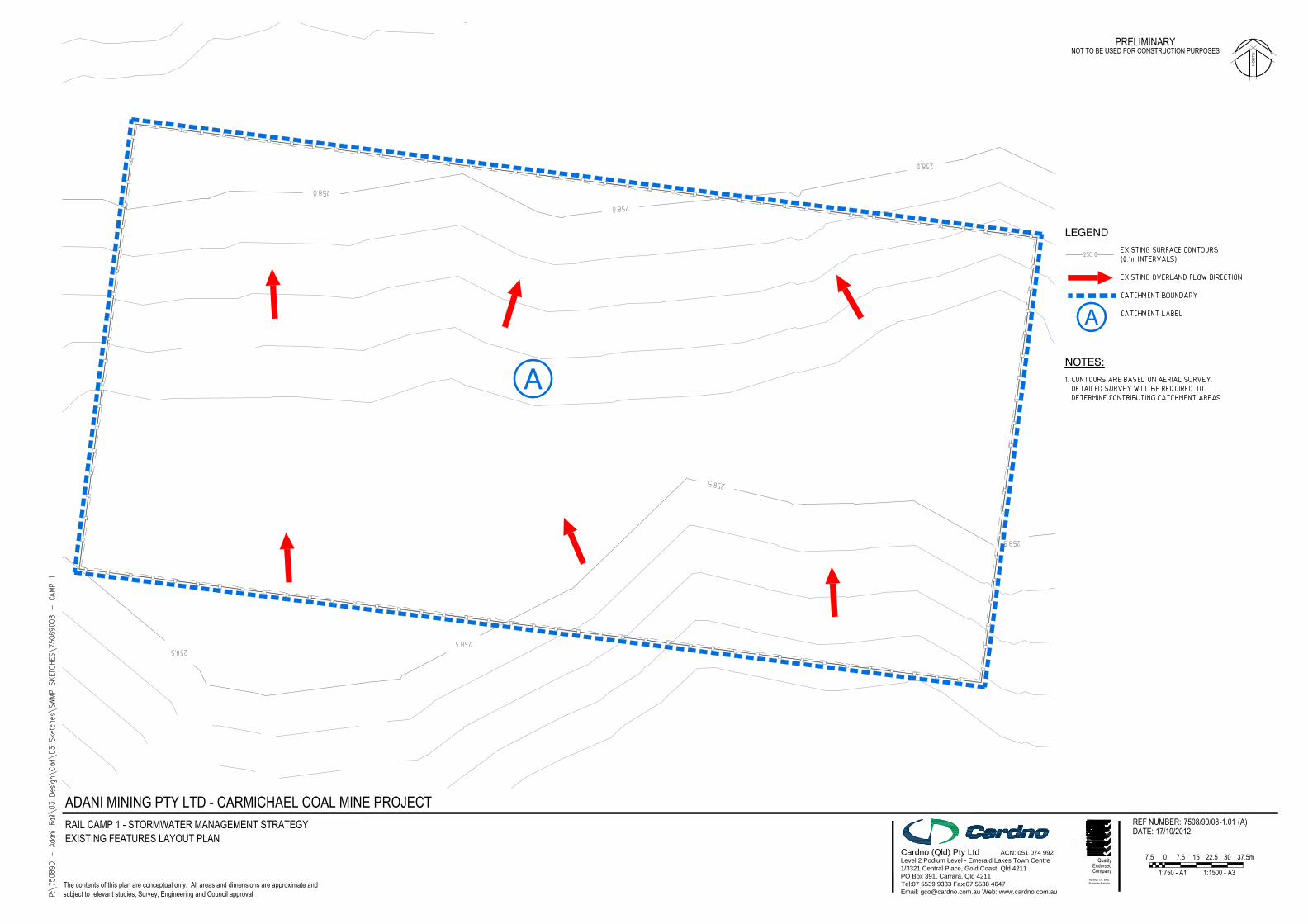
A review of available aerial contour information showed that the camp site is situated at a level of
approximately RL258.5m AHD. The existing site topography generally slopes to the north-west corner of the
site at a grade of approximately 0.2%. Refer to Cardno drawing number 7508/90/08/-1.01 for the existing
topography of the rail camp site.
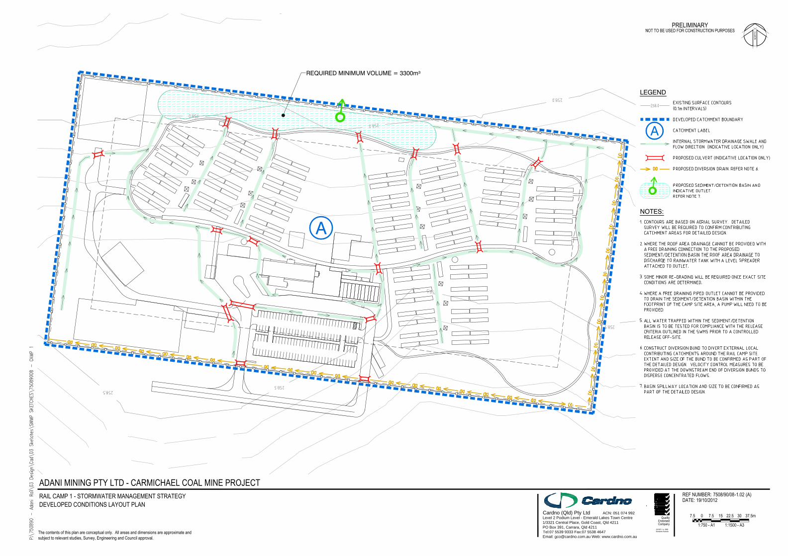
2.2 Developed Site Description
It is proposed to establish a workers camp to support the construction of the proposed railway linking the
Carmichael Coal Mine with the port terminals situated to the east. The developed site is to contain
accommodation units to house approximately 400 staff with all associated services including sewerage and
water treatment plants.
As minimal bulk earthworks are anticipated in order to construct the camp site, the developed condition site
topography is expected to generally resemble the existing conditions with the subject site to continue to
grade to the north-western corner of the camp. Refer to Cardno drawing number 7508/90/08/-1.02 for the
proposed development layout of Rail Camp 1.
Stormwater Management Strategy Carmichael Coal Mine Rail Construction Camp 1
30/10/2012 Cardno 3
3 Performance Criteria
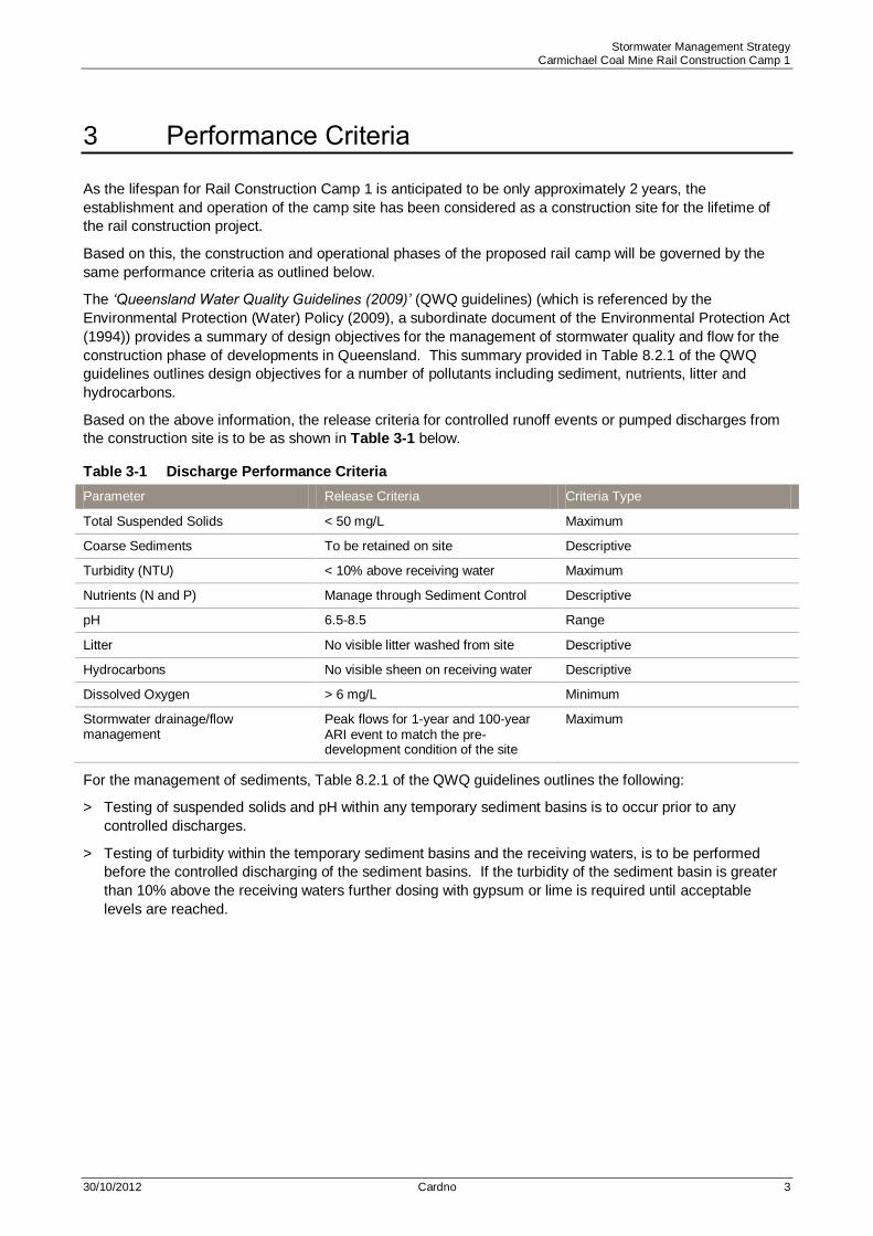
As the lifespan for Rail Construction Camp 1 is anticipated to be only approximately 2 years, the
establishment and operation of the camp site has been considered as a construction site for the lifetime of
the rail construction project.
Based on this, the construction and operational phases of the proposed rail camp will be governed by the
same performance criteria as outlined below.
The ‘Queensland Water Quality Guidelines (2009)’ (QWQ guidelines) (which is referenced by the
Environmental Protection (Water) Policy (2009), a subordinate document of the Environmental Protection Act
(1994)) provides a summary of design objectives for the management of stormwater quality and flow for the
construction phase of developments in Queensland. This summary provided in Table 8.2.1 of the QWQ
guidelines outlines design objectives for a number of pollutants including sediment, nutrients, litter and
hydrocarbons.
Based on the above information, the release criteria for controlled runoff events or pumped discharges from
the construction site is to be as shown in Table 3-1 below.
Discharge Performance Criteria Table 3-1
Parameter Release Criteria Criteria Type
Total Suspended Solids < 50 mg/L Maximum
Coarse Sediments To be retained on site Descriptive
Turbidity (NTU) < 10% above receiving water Maximum
Nutrients (N and P) Manage through Sediment Control Descriptive
pH 6.5-8.5 Range
Litter No visible litter washed from site Descriptive
Hydrocarbons No visible sheen on receiving water Descriptive
Dissolved Oxygen > 6 mg/L Minimum
Stormwater drainage/flow management
Peak flows for 1-year and 100-year ARI event to match the pre-development condition of the site
Maximum
For the management of sediments, Table 8.2.1 of the QWQ guidelines outlines the following:
> Testing of suspended solids and pH within any temporary sediment basins is to occur prior to any
controlled discharges.
> Testing of turbidity within the temporary sediment basins and the receiving waters, is to be performed
before the controlled discharging of the sediment basins. If the turbidity of the sediment basin is greater
than 10% above the receiving waters further dosing with gypsum or lime is required until acceptable
levels are reached.
Stormwater Management Strategy Carmichael Coal Mine Rail Construction Camp 1
30/10/2012 Cardno 4
4 Stormwater Management Strategy
4.1 Stormwater Quality
Based on the limited lifespan of Rail Construction Camp 1 and the site‟s proximity to the adjacent railway
corridor construction area, the primary objective of the proposed stormwater quality management strategy
will be to control soil erosion on site and minimise sediment discharge to the downstream receiving local
water courses using appropriate best management practices.
Refer to Cardno drawing number 7508/90/08/-1.02 for an indicative layout of the stormwater quality
management measures proposed to be adopted to treat the contributing local catchment areas of rail
construction camp 1.
4.1.1 Available Management Practices
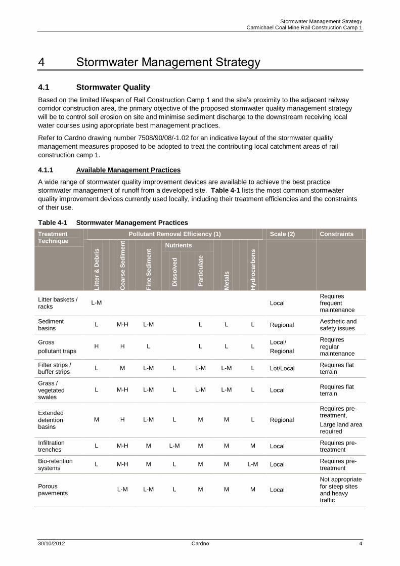
A wide range of stormwater quality improvement devices are available to achieve the best practice
stormwater management of runoff from a developed site. Table 4-1 lists the most common stormwater
quality improvement devices currently used locally, including their treatment efficiencies and the constraints
of their use.
Stormwater Management Practices Table 4-1
Treatment Technique
Pollutant Removal Efficiency (1) Scale (2) Constraints
Lit
ter
& D
eb
ris
Co
ars
e S
ed
imen
t
Fin
e S
ed
imen
t
Nutrients
Meta
ls
Hyd
rocarb
on
s
Dis
so
lved
Part
icu
late
Litter baskets / racks
L-M Local Requires frequent maintenance
Sediment basins
L M-H L-M L L L Regional Aesthetic and safety issues
Gross
pollutant traps H H L L L L
Local/
Regional
Requires regular maintenance
Filter strips / buffer strips
L M L-M L L-M L-M L Lot/Local Requires flat terrain
Grass / vegetated swales
L M-H L-M L L-M L-M L Local Requires flat terrain
Extended detention basins
M H L-M L M M L Regional
Requires pre-treatment,
Large land area required
Infiltration trenches
L M-H M L-M M M M Local Requires pre-treatment
Bio-retention systems
L M-H M L M M L-M Local Requires pre-treatment
Porous pavements
L-M L-M L M M M Local
Not appropriate for steep sites and heavy traffic

Stormwater Management Strategy Carmichael Coal Mine Rail Construction Camp 1
30/10/2012 Cardno 5
Treatment Technique
Pollutant Removal Efficiency (1) Scale (2) Constraints
Lit
ter
& D
eb
ris
Co
ars
e
Sed
imen
t
Fin
e S
ed
imen
t Nutrients
Meta
ls
Hyd
rocarb
on
s
Dis
so
lved
Part
icu
late
Constructed wetlands
M-H H M H H M-H M Regional
Requires pre-treatment, Not appropriate for steep sites, Large land area required
Community education
Regional Community participation
Information Source: Queensland Urban Drainage Manual Table 11.05.4 (Typical pollutant removal efficiencies of
treatment systems (2007). Benefit Ranking: L = Low Benefit, M = Medium Benefit, H = High Benefit.
Notes:
(1) Removal rates are provided for information only with the efficiency rating subject to adequate design. The actual
removal rates used for detailed water quality modelling purposes should be in accordance with MUSIC Modelling
Guidelines Version 1.0 – 2010 prepared by Water by Design.
(2) Scales: Lot – less than 1 ha; Local – 1 to 10 ha; Regional – greater than 10 ha.
Given the features of the subject site, a number of the measures listed in Table 4-1 above would not be
considered appropriate to be incorporated into the stormwater treatment train for the proposed camp site.
Provided below is information on a number of the listed stormwater quality improvement devices including
the suitability of these devices to be incorporated into the development of the subject site to treat stormwater
runoff from the proposed construction camp site.
Litter Baskets/Racks
Litter baskets and trash racks are generally located upstream of other treatment measures such as extended
detention basins or constructed wetlands. They are primarily used as a pre-treatment device for stormwater
runoff, removing litter, debris and other gross pollutants from the runoff before it discharges into other
secondary and tertiary treatment devices located downstream.
Gross Pollutant Traps (GPT) / Oil & Grit Separators
GPT / Oil and Grit Separators incorporated into the stormwater treatment train can contribute to the effective
removal of solid pollutants, sediments and hydrocarbons from stormwater runoff from driveway and roadway
areas of the proposed development site.
Generally GPTs and Oil and Grit Separators shall be designed to treat flows generated by the 3 month
Average Recurrence Interval (ARI) rainfall event.
Sediment Basins
During the construction phase of the development sediment loads are expected to be higher due to areas
being cleared and exposed for the construction of roads, services and buildings. It is recommended that as
part of the erosion and sediment control plan prepared for the construction phase of the development some
form of sediment basin will be utilised to help manage sediment transport off-site.
The use of sediment basins is considered appropriate for this rail construction camp development.

Stormwater Management Strategy Carmichael Coal Mine Rail Construction Camp 1
30/10/2012 Cardno 6
Vegetated Filter Strips / Buffer Strips
Filter / buffer strips can be either areas of planted vegetation or strips of retained vegetation left in its natural
state. These vegetated areas may provide both an effective way of reducing peak flows and improving
stormwater runoff quality. During the construction phase of the development the retention of existing
vegetation in-conjunction with other erosion control measures can assist to stabilise exposed areas. In the
case of the proposed development areas that grade away from the proposed road drainage network buffer
strips along the rear of the allotments are considered one of the key stormwater management techniques,
particularly where no other stormwater treatment techniques are possible. Upon completion of the rail camp
construction works any exposed areas should be turfed, seeded or landscaped as soon as possible to
reduce the risk of erosion.
It should be noted that in order for buffer strips to be effective, flow must be overland, and not concentrated.
Therefore, flow spreaders may be required in conjunction with buffer strips to ensure optimal performance,
particularly for those areas which drain away from the road.
The use of vegetated filter / buffer strips is considered appropriate for this development.
Grassed / Vegetated Swales
Grassed / vegetated swales are designed to treat stormwater runoff by ensuring sufficient detention time to
allow the removal of nutrients and fine sediments. This is achieved through filtration and infiltration.
Hydrocarbon removal will also be achieved through filtration and attachment to vegetation where biological
breakdown of the hydrocarbons can occur.
Swale lengths and widths can vary dependent on the site conditions, however to operate most effectively
swales need to be located on relatively flat grades no steeper than 4-5%. The use of vegetated swales is
limited in steep slope areas, unless suitable scour protection measures are incorporated.
The use of grassed / vegetated swales is considered appropriate for this development.
Infiltration Trenches
Infiltration trenches are predominantly dry shallow grassed areas that trap the first flush runoff. The trapped
runoff then infiltrates through the filtration medium removing fine sediment and nutrients. The base of the
infiltration trench should be lined with an adequately designed sub-surface perforated pipe drainage network
to convey filtered runoff to the trench outlet before discharging to the downstream receiving environment.
Bio-retention Systems
Similar to vegetated swales, bio-retention systems are designed to treat stormwater runoff by ensuring
sufficient detention time to allow the removal of nutrients and fine sediments. This is achieved through
filtration, plant uptake, adsorption and biological degradation. Hydrocarbon removal will also be achieved
through filtration and attachment to vegetation where the biological breakdown of hydrocarbons can occur.
Bio-retention systems contain an infiltration filter media, typically filled with sandy loam. All runoff collected
within the system for the design storm event must pass through this filter. The filter media must be capable
of sustaining vegetation growth as the vegetation is responsible for much of the uptake of nutrients within the
system. The base of the bio-retention systems should be lined with an adequately designed sub-surface
perforated pipe drainage network to convey the filtered runoff to the system outlet before discharging to the
receiving system.
Bio-retention systems can be used in both flat areas and in steeper areas by stepping the system. Bio-
retention systems can also be incorporated into the base of detention basins combining both stormwater
quality and quantity into one area.
Porous Pavements
Porous pavements vary with design, but generally incorporate a surface material consisting of a grid / lattice
system, modular clay / concrete blocks, or open-graded asphalt / concrete pavements with much of the fine
aggregate material omitted. The surface material is bedded on a coarse sand filter layer constructed over a
gravel drainage layer. The use of porous pavements can assist in the removal of fine particulate matter,
hydrocarbons, nutrients and soluble pollutants from stormwater runoff.

Stormwater Management Strategy Carmichael Coal Mine Rail Construction Camp 1
30/10/2012 Cardno 7
Porous pavements are suited most to areas of low traffic volume and low runoff volume. Porous pavements
are most effective when used at grades of less than 5%. Because of this, porous pavements are
recommended to be used in the parking areas only.
Rainwater Tanks
In addition to providing a low cost supply of water to assist in reducing demand on water supply, rainwater
tanks can also provide a reduction in peak flow rates from rainfall events with the provision of additional
storage volume.
Level Spreader Devices
For roof area drainage that cannot be connected to a piped drainage network the concentrating of roof water
runoff at a single discharge outlet can lead to erosion and scour problems. By utilising a level spreader at
the outlet to disperse the overflows over a larger area, the flows will be less concentrated and velocities will
be reduced, reducing the risk of erosion and the incidence of re-suspension of sediments. Level / flow
spreaders should be located away from high pedestrian traffic areas and be directed towards vegetated
buffer strips or other landscaped areas.
Constructed Wetlands
Constructed wetlands are a water quality treatment system comprising of an inlet pond, to remove coarse
sediments, and a macrophyte zone, to remove fine particulates and soluble pollutants. Additionally,
constructed wetlands also provide landscape value, passive recreation, wildlife habitat and flood control.
Wetlands are particularly useful on sites constrained by water and environmental sensitivity as they can be
incorporated as an upstream component of existing waterbodies and environmentally sensitive aquatic
features.
The dominant feature of the wetland is the macrophyte zone which comprises of vegetated marshes, shallow
and deep pools.
Wetlands require reasonably large flat areas of land. Currently, bio-retention systems provide superior
performance with a reduced footprint compared to wetlands. Given the relatively low rainfall and high
evaporation that occurs in the region, there are also concerns in relation to constructed wetlands being dry
for prolonged periods. Therefore this type of treatment device is not considered appropriate for the rail
construction camp site.
4.1.2 Adopted Strategy
Based on the site constraints the following stormwater quality improvement devices and management
practices are considered appropriate to be incorporated in the development of rail construction camp 1.
Rainwater tanks and level spreader devices
Due to the flat grades of the rail camp site it may not be possible to direct all roof area drainage to a piped
drainage network that will be able to free drain to the nominated stormwater treatment and detention basins.
Therefore in these instances it is suggested that the roof area drainage discharge to rainwater tank with a
level spreader device attached to the outlet. As indicated above, this would assist in dispersing the outflows
over a larger area to reduce the risk of erosion and the incidence of re-suspension of sediments.
Vegetated Swales
As grades across rail camp 1 are expected to be generally less than 4-5% the use of vegetated swales for
stormwater treatment is considered appropriate. As noted above, due to the relatively flat grades across the
subject site vegetated swales will be used for conveyance purposes throughout much of the site as an
alternative to conventional piped drainage which is expected to be limited by depth.
Sediment Basins
As the primary target of this stormwater management strategy is to control soil erosion and minimise
sediment transport from the camp site this type of device is considered the most appropriate control device
for the rail construction camp.

Stormwater Management Strategy Carmichael Coal Mine Rail Construction Camp 1
30/10/2012 Cardno 8
With the lifespan of the construction camp anticipated to be approximately 2 years, the use of alternative
devices such as bio-retention basins are limited as these types of devices generally take a period of
approximately 2 years to appropriately establish.
The flexibility in the shape of sediment basins combined with the efficient pollutant retention rates for
sediments that these systems provide make sediment basins ideal for the rail construction camp site.
In addition to the above listed stormwater management practices, other principals of water sensitive urban
design that can be incorporated into the development of the rail construction camp include:
> Retention of existing drainage features, where possible;
> Protection of natural systems by limiting development to non-sensitive areas and providing adequate
buffers between development and natural systems;
> Non-worsening of peak flow rates from site.
It should be noted that this stormwater management strategy has been based on a preliminary layout.
Although stormwater treatment practices have been recommended for use in certain areas throughout the
subject site, a number of treatment measures may be appropriate and the key principles of the stormwater
management strategy will remain applicable despite potential layout changes.
Should the detailed design bring about changes to the proposed layout, Section 4.1.1 of this stormwater
management strategy provides a list of alternative treatment practices that may be suitable for the site and
could potentially be designed to meet the nominated water quality objectives. The key aim of this stormwater
management strategy is that the practices listed as suitable for the site should be used in a manner which
results in best practice stormwater management measures being incorporated into the development.
4.2 Stormwater Quantity
The intent of this stormwater quantity strategy for rail construction camp 1 is to manage runoff generated
from the local contributing catchment area (i.e. the camp site area) only. Based on this, it is proposed to
construct perimeter bunds along the upstream boundaries of the subject site to divert the local external
contributing catchment areas around the camp site.
A regional hydrologic and hydraulic assessment of the railway corridor is currently being undertaken by
others.
The purpose of this stormwater quantity management strategy is to avoid impacts on the downstream
receiving properties and infrastructure, by ensuring that the peak flows discharging from the developed
condition camp site area are equivalent to, or less than the peak flows expected from the existing condition
site. It is proposed to incorporate an on-site detention basin into the rail camp site to control the developed
condition peak flows discharging from the subject site for rainfall events up to and including the 100 year ARI
event.
To control the peak rates of discharge from the proposed detention basin it will be necessary for the outlet
arrangement to be designed to maintain peak flows equivalent to the existing condition peak discharges. It
is noted that where a free draining piped outlet cannot be provided to drain the proposed detention basin
within the footprint of the camp site area, a pump system will need to be provided.
The proposed detention basin will also be utilised as a sediment retention basin for water quality purposes.
All water trapped within the sediment / detention basin is to be tested for compliance with the release criteria
outlined in Table 3-1 prior to a controlled release from the site or alternatively the water could be used for
dust suppression or irrigation.
Due to the flat nature of the site, not all stormwater runoff generated within the camp site will be able to be
conveyed to the proposed on-site detention basin with the use of a conventional pit and pipe drainage
system. As a result it is proposed to use drainage swales to convey runoff to the nominated detention basin
location.
The indicative location and minimum size of the proposed basin is shown on Cardno drawing number
7508/90/08/-1.02. Calculations for the sizing of the detention basin can be found in Section 6 of this report.

Stormwater Management Strategy Carmichael Coal Mine Rail Construction Camp 1
30/10/2012 Cardno 9
5 Stormwater Quality Assessment
As outlined above, the lifespan for Rail Construction Camp 1 is anticipated to be only approximately 2 years
and therefore the operation of the camp site has been considered as a construction site for the lifetime of the
rail construction project.
The works to be carried out on the site of rail construction camp 1 have the potential to increase the level of
sediment laden runoff discharging from the site for the lifespan of the construction project. Based on this, the
following assessment for the rail camp site has been undertaken to determine the on-site sediment retention
storage requirements that will be necessary to retain the expected soil loss generated from the camp site
construction area. Refer to Cardno drawing number 7508/90/08/-1.02 for the subject site local catchment
areas adopted for the preliminary on-stormwater quality assessment.
5.1 Soil Loss Calculations
Data obtained from the Australian Soil Resource Information System on the 12th October 2012 shows the
soils to be expected on the subject site are medium clays with an approximate clay content of 40 – 50%.
The data obtained was from the national soil grid. This soil type is considered to be a dispersive soil (type D)
and based on the Revised Universal Soil Loss Equation (RUSLE) the predicted soil loss rate has been
estimated for each of the disturbed catchment areas located within the subject site.
Catchment parameters for the disturbed area of the subject site were based on existing contour information.
These catchment parameters have been summarised in Table 5-1 below.
Catchment Parameters Table 5-1
Catchment No. Internal / Site Catchment Area (ha) Approx. Average Site Slope (%)
A 9.31 0.2
The results of the soil loss assessment using the revised soil loss equation are summarised in Table 5-2
below. For more detailed information refer to the sediment loss calculations provided in Appendix C of this
report.
Soil Loss Parameters Table 5-2
Catchment No.
Rainfall Erosivity Factor (R)
Soil Erodibility Factor (K)
Slope Length / Gradient
Factor (LS)
Erosion Control Practice
Factor (P)
Ground Cover (C)
Soil Loss (A) (t/ha/yr)
Sediment Storage Volume
(m³)
A 2627 0.02 0.24 1.3 1.0 12 190
Based on the information above, the soil loss within the disturbed area of catchment A has been estimated to
be equivalent to Soil Loss Class 1 (0 to 150 tonnes/ha/yr), which classifies the site as a very low erosion risk
as outlined in Table 3.1 of the „Best Practice Erosion and Sediment Control (2008)‟ guidelines prepared by
the International Erosion Control Association – Australasia.

Stormwater Management Strategy Carmichael Coal Mine Rail Construction Camp 1
30/10/2012 Cardno 10
5.2 Sediment Basin Calculations
In conjunction with the above information, the calculations for the total sediment basin volume have been
carried out and shown in Table 5-3 below.
Sediment Basin Calculations Table 5-3
Volumetric Runoff Coefficient (Cv)
Catchment Area of Basin (A)
5 day total rainfall depth (R) [85%ile,
5day
Settling Zone Volume
(10xCvxAxR)
Total Basin Volume (m³)
0.58 9.31 32.50 1755 1945
A comparison of the total storage volumes required for sediment retention and for on-site detention will be
carried out in Section 6 of this report. This comparison will be made to determine which design conditions
will be considered as the critical case.
Stormwater Management Strategy Carmichael Coal Mine Rail Construction Camp 1
30/10/2012 Cardno 11
6 Stormwater Quantity Assessment
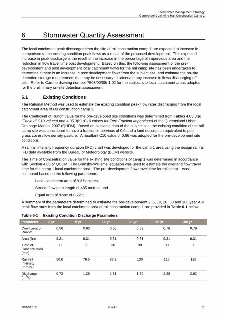
The local catchment peak discharges from the site of rail construction camp 1 are expected to increase in
comparison to the existing condition peak flows as a result of the proposed development. This expected
increase in peak discharge is the result of the increase in the percentage of impervious area and the
reduction in flow travel time post development. Based on this, the following assessment of the pre-
development and post development local catchment flows for the rail camp site has been undertaken to
determine if there is an increase in post development flows from the subject site, and estimate the on-site
detention storage requirements that may be necessary to attenuate any increase in flows discharging off-
site. Refer to Cardno drawing number 7508/90/08/-1.02 for the subject site local catchment areas adopted
for the preliminary on-site detention assessment.
6.1 Existing Conditions
The Rational Method was used to estimate the existing condition peak flow rates discharging from the local
catchment area of rail construction camp 1.
The Coefficient of Runoff value for the pre-developed site conditions was determined from Tables 4.05.3(a)
(Table of C10 values) and 4.05.3(b) (C10 values for Zero Fraction Impervious) of the Queensland Urban
Drainage Manual 2007 (QUDM). Based on available data of the subject site, the existing condition of the rail
camp site was considered to have a fraction impervious of 0.0 and a land description equivalent to poor
grass cover / low density pasture. A resultant C10 value of 0.66 was adopted for the pre-development site
conditions.
A rainfall intensity frequency duration (IFD) chart was developed for the camp 1 area using the design rainfall
IFD data available from the Bureau of Meteorology (BOM) website.
The Time of Concentration value for the existing site conditions of camp 1 was determined in accordance
with Section 4.06 of QUDM. The Bransby-Williams‟ equation was used to estimate the overland flow travel
time for the camp 1 local catchment area. The pre-development flow travel time for rail camp 1 was
estimated based on the following parameters.
- Local catchment area of 9.3 hectares;
- Stream flow path length of 485 metres; and
- Equal area of slope of 0.22%.
A summary of the parameters determined to estimate the pre-development 2, 5, 10, 20, 50 and 100 year ARI
peak flow rates from the local catchment area of rail construction camp 1 are provided in Table 6-1 below.
Existing Condition Discharge Parameters Table 6-1
Parameter 2 yr 5 yr 10 yr 20 yr 50 yr 100 yr
Coefficient of Runoff
0.56 0.63 0.66 0.69 0.76 0.79
Area (ha) 9.31 9.31 9.31 9.31 9.31 9.31
Time of Concentration (min)
30 30 30 30 30 30
Rainfall Intensity (mm/hr)
50.6 79.5 88.2 100 116 128
Discharge (m
3/s)
0.73 1.29 1.51 1.79 2.28 2.62
Stormwater Management Strategy Carmichael Coal Mine Rail Construction Camp 1
30/10/2012 Cardno 12
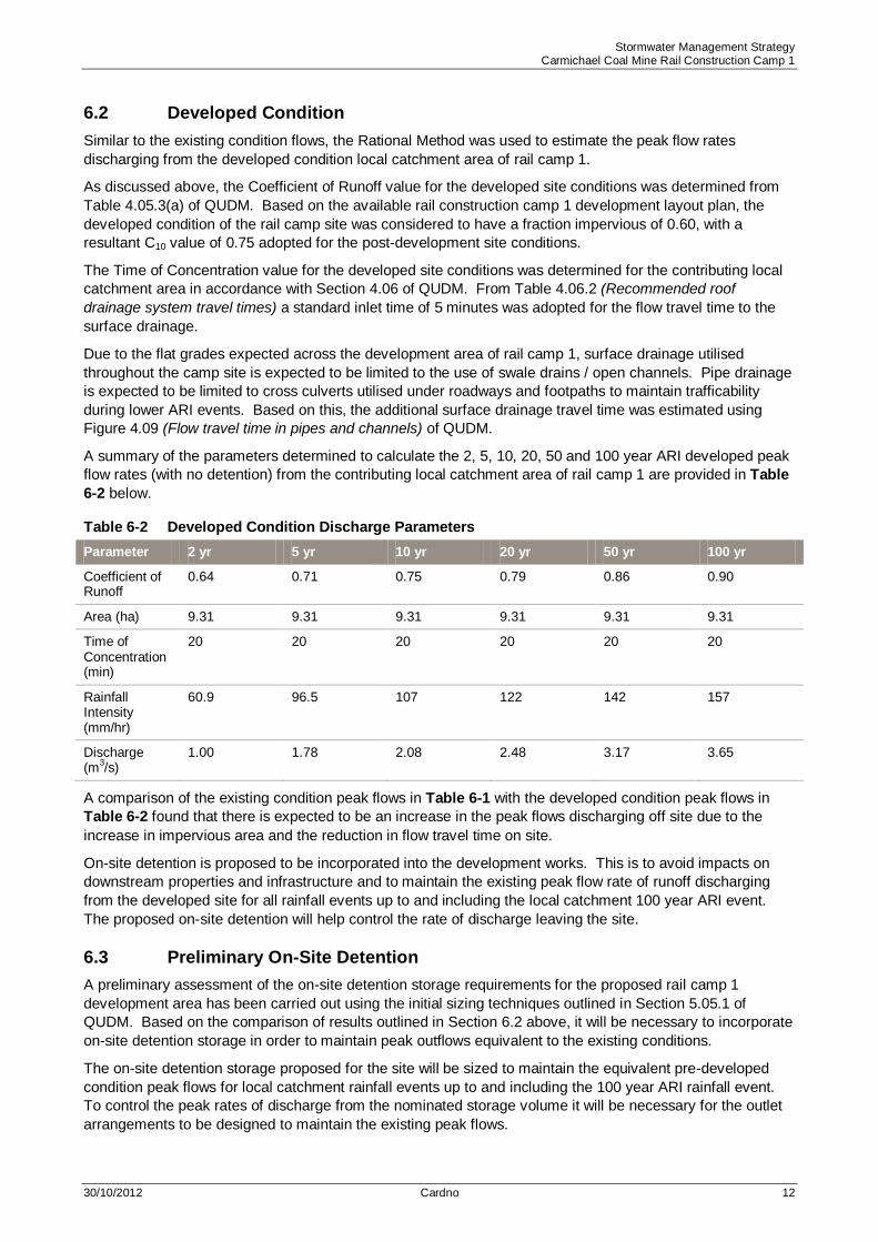
6.2 Developed Condition
Similar to the existing condition flows, the Rational Method was used to estimate the peak flow rates
discharging from the developed condition local catchment area of rail camp 1.
As discussed above, the Coefficient of Runoff value for the developed site conditions was determined from
Table 4.05.3(a) of QUDM. Based on the available rail construction camp 1 development layout plan, the
developed condition of the rail camp site was considered to have a fraction impervious of 0.60, with a
resultant C10 value of 0.75 adopted for the post-development site conditions.
The Time of Concentration value for the developed site conditions was determined for the contributing local
catchment area in accordance with Section 4.06 of QUDM. From Table 4.06.2 (Recommended roof
drainage system travel times) a standard inlet time of 5 minutes was adopted for the flow travel time to the
surface drainage.
Due to the flat grades expected across the development area of rail camp 1, surface drainage utilised
throughout the camp site is expected to be limited to the use of swale drains / open channels. Pipe drainage
is expected to be limited to cross culverts utilised under roadways and footpaths to maintain trafficability
during lower ARI events. Based on this, the additional surface drainage travel time was estimated using
Figure 4.09 (Flow travel time in pipes and channels) of QUDM.
A summary of the parameters determined to calculate the 2, 5, 10, 20, 50 and 100 year ARI developed peak
flow rates (with no detention) from the contributing local catchment area of rail camp 1 are provided in Table
6-2 below.
Developed Condition Discharge Parameters Table 6-2
Parameter 2 yr 5 yr 10 yr 20 yr 50 yr 100 yr
Coefficient of Runoff
0.64 0.71 0.75 0.79 0.86 0.90
Area (ha) 9.31 9.31 9.31 9.31 9.31 9.31
Time of Concentration (min)
20 20 20 20 20 20
Rainfall Intensity (mm/hr)
60.9 96.5 107 122 142 157
Discharge (m
3/s)
1.00 1.78 2.08 2.48 3.17 3.65
A comparison of the existing condition peak flows in Table 6-1 with the developed condition peak flows in
Table 6-2 found that there is expected to be an increase in the peak flows discharging off site due to the
increase in impervious area and the reduction in flow travel time on site.
On-site detention is proposed to be incorporated into the development works. This is to avoid impacts on
downstream properties and infrastructure and to maintain the existing peak flow rate of runoff discharging
from the developed site for all rainfall events up to and including the local catchment 100 year ARI event.
The proposed on-site detention will help control the rate of discharge leaving the site.
6.3 Preliminary On-Site Detention
A preliminary assessment of the on-site detention storage requirements for the proposed rail camp 1
development area has been carried out using the initial sizing techniques outlined in Section 5.05.1 of
QUDM. Based on the comparison of results outlined in Section 6.2 above, it will be necessary to incorporate
on-site detention storage in order to maintain peak outflows equivalent to the existing conditions.
The on-site detention storage proposed for the site will be sized to maintain the equivalent pre-developed
condition peak flows for local catchment rainfall events up to and including the 100 year ARI rainfall event.
To control the peak rates of discharge from the nominated storage volume it will be necessary for the outlet
arrangements to be designed to maintain the existing peak flows.

Stormwater Management Strategy Carmichael Coal Mine Rail Construction Camp 1
30/10/2012 Cardno 13
A comparison of the existing and developed condition peak flows for the rail camp site indicated that the 100
year ARI storm event resulted in the greatest increase in peak discharge. The results of the preliminary on-
site detention analysis indicate that detention storage volume of approximately 3305m3 will be required to
detain the increase in the 100 year ARI discharge and maintain the equivalent pre-developed 100 year ARI
peak flow discharging off site.
It should be noted that the volume outlined may be subject to change if the final catchment areas differ from
those adopted for this assessment. The stage storage characteristics and outlet configuration of the
detention basin will be verified as part of the detailed design of the civil works for rail camp 1.
It is proposed to incorporate the stormwater detention and treatment into one common basin. A comparison
of the total storage volumes required for sediment retention, as outlined in Section 5 of this report, and for
on-site detention has indicated that the volume required for on-site detention is more critical. Therefore the
total storage volume adopted for the rail camp 1 stormwater treatment and detention basin is a minimum of
3305m3. Refer to Cardno drawing number 7508/90/08/-1.02 for the indicative layout and configuration of the
stormwater treatment and detention basin for rail construction camp 1.
In accordance with Section 5.11 of QUDM it is recommended that any ponding within the basin should be
limited to 1.2 metres at the deepest point above the basin invert. For deeper basins, suitable safety
provisions such as refuge mounds within large basins, fences and warning signs should be provided.
6.4 Other Drainage Issues
6.4.1 Diversion of External Catchments
As the intent of this strategy is to manage the runoff from the rail construction camp area only, it is proposed
to construct perimeter bunds along the upstream boundaries of the subject site to divert the local external
contributing catchment areas around the camp site. Refer to Cardno drawing number 7508/90/08/-1.02 for
the indicative locations of the external catchment diversion bunds proposed for rail camp 1. The final
alignment and profile required for the diversion bunds will be confirmed as part of the detailed design of the
civil works for rail camp 1.

Stormwater Management Strategy Carmichael Coal Mine Rail Construction Camp 1
30/10/2012 Cardno 14
7 Monitoring and Maintenance Schedules
7.1 Monitoring Schedule
A monitoring program will be established for the stormwater management devices as outlined below and
shown in Table 7-1, Table 7-2, Table 7-3 and Table 7-4.
Monitoring Program for Sediment Basins Table 7-1
MONITORING ACTIVITY FREQUENCY
Inspect sediment basin
- During construction
- After each runoff event
- Weekly during wet season
- Prior to “stop work” or “site shutdown”
Inspect submerged inflow pipes After each runoff event
Testing of suspended solids, pH, and dissolved oxygen
- Prior to controlled release
- Immediately following rain events > 25mm in a 24 hour period
To maximise the effectiveness of the stormwater management measures for the roof drainage areas that do
not connect directly to a piped drainage system, the following activities are suggested to regularly visually
monitor the condition of the rainwater tanks and level spreader outlets.
Monitoring Program for Rainwater Tanks Table 7-2
MONITORING ACTIVITY FREQUENCY
Observe water surcharging from surcharge weir/pipe/pit of tank After major storm events > 25mm in 24 hrs
Inspect silt / litter trap After major storm events > 25mm in 24 hrs or 3 monthly
Inspect structural integrity / condition of device 6 monthly
Monitoring Program for Level Spreader Devices Table 7-3
MONITORING ACTIVITY RECOMMENDED FREQUENCY
Inspect for incidents of erosion / scour of soils After major storm events > 25mm in 24 hrs or 3 monthly
Inspect for weed inundation / litter accumulation
3 monthly Inspect for excessive wear & damage
Inspect for build-up of sediments
Inspect health of vegetation

Stormwater Management Strategy Carmichael Coal Mine Rail Construction Camp 1
30/10/2012 Cardno 15
In the case of vegetated buffers and vegetated swales, the collection of water quality samples is unlikely to
yield valuable results. Given this, no sample based monitoring is recommended for these treatment
systems. Instead, an inspection based monitoring and maintenance scheme as detailed below is considered
appropriate for these types of devices.
Monitoring Program for Vegetated Swales Table 7-4
MONITORING ACTIVITY FREQUENCY
Inspect for erosion / scour of invert & batters After major storm events > 25mm in 24 hrs or 3 monthly
Inspect for weed inundation / litter & debris accumulation 3 monthly
Inspect for inappropriate access, excessive wear & damage to invert & batters
3 monthly
Inspect for build-up of sediments 3 monthly
Inspect condition of vegetation such as vegetation health & density 3 monthly
Inspect condition of inlet & outlet structures After major storm events > 25mm in 24 hrs or 3 monthly
7.2 Maintenance Schedule
The on-going performance of the stormwater management devices will be dependent on the maintenance
conducted.
The maintenance programs as outlined below and detailed in Table 7-5, Table 7-6, Table 7-7 and Table 7-8
are to be implemented for the stormwater treatment devices.
Maintenance Program for Sediment Basins Table 7-5
MAINTENANCE ACTIVITY FREQUENCY
Clean out accumulated sediment Every 2 years as per sediment basin calculations or as required by results of monitoring
Check visible pipes for leaks 6 monthly or as required by results of monitoring
Check fill material for settlement 6 monthly or as required by results of monitoring
Remove all trash from basin and riser 6 monthly or as required by results of monitoring
De-silt submerged inflow pipes 6 monthly or as required by results of monitoring
Sediment basins must be operated and maintained in an effective operational condition. These structures
must not be allowed to accumulate sediment volumes in excess of forty per cent (40%) sediment storage
design capacity. Where sedimentation basins are used a marker shall be placed within the basin to show
the level above which the design capacity occurs. Materials removed from sediment retention devices must
be disposed of in a manner approved by the consent authority that does not cause pollution.
Maintenance Program for Rainwater Tanks Table 7-6
MAINTENANCE ACTIVITY FREQUENCY
Clean out silt / litter trap 6 monthly or as required by results of monitoring Remove debris from surcharge weir / pipe / pit
Dewater and clean out / de-silt tank As required by monitoring

Stormwater Management Strategy Carmichael Coal Mine Rail Construction Camp 1
30/10/2012 Cardno 16
Maintenance Program for Level Spreader Devices Table 7-7
MAINTENANCE ACTIVITY FREQUENCY
Repairs to landscaping / level spreaders
As required by monitoring Watering, re-vegetating, grass cutting
Removal of litter, debris, weeds & excessive sediment build up
Maintenance Program for Vegetated Swales Table 7-8
MAINTENANCE ACTIVITY FREQUENCY
Repairs to swale profile As required by results of monitoring
Irrigating, infilling of vegetation to maintain sufficient cover As required by results of monitoring
Removal of litter, debris, weeds & excessive sediment build up 6 monthly or as required by results of monitoring
Mowing / pruning of swale vegetation to maintain optimal vegetation height As required by results of monitoring
Reforming of any swale profile will be required when the design flow area of the swale is reduced by 25%.

Stormwater Management Strategy Carmichael Coal Mine Rail Construction Camp 1
30/10/2012 Cardno 17
8 Conclusions
In preparing this conceptual stormwater management strategy preliminary water quality and quantity
assessments were undertaken for rail construction camp 1.
The objectives of this stormwater management strategy were to meet the performance criteria outlined in
Table 3-1 of this report. The outcome of this preliminary investigation has recommended the inclusion of a
number of stormwater quality and quantity management measures detailed herein and summarised as
follows:
> Numerous vegetated swales for treatment and conveyance purposes as indicatively shown on Cardno
7508/90/08/-1.02; and
> One constructed sediment basin as described in Sections 5 and 6, and indicatively shown on Cardno
7508/90/08/-1.02.
The detailed design of the treatment and detention devices will need to comply with the information outlined
within this stormwater management strategy, and with the relevant authority guidelines.

Stormwater Management Strategy Carmichael Coal Mine Rail Construction Camp 1
30/10/2012 Cardno 18
9 References
Department of Environment and Resource Management 2009, Queensland Water Quality Guidelines (2009),
Version 3 September 2009, Brisbane, QLD
Water by Design 2010, MUSIC Modelling Guidelines Version 1.0 – 2010, Brisbane, QLD
International Erosion Control Association (Australasia) 2008, Best Practice Erosion and Sediment Control,
November 2008, Picton, NSW
Department of Natural Resources and Water 2007, Queensland Urban Drainage Manual 2007 (QUDM),
Volume 1 Second Edition 2007, Brisbane, QLD

Stormwater Management Strategy Carmichael Coal Mine Rail Construction Camp 1
30/10/2012 Cardno 19
APPENDIX
A REFERENCE DRAWINGS

ADAMIN MINING Pty Ltd RAIL CAMP 1
DATE DRAWING NO ISSUE
landscape architectureurban design
environmental management A18.10.12 SP126801 -RC01-01
MORAHBAH
RAIL CAMP TWORAIL CAMP
THREE
MINING CAMP
RAIL CAMP ONE
CONTEXT PLAN
SITE PHOTOS
RAIL CAMP ONE
VIE
W N
ORTH
VIEW
SOU
THVI
EW W
EST
VIEW
EAS
T
scale 1:40,000 @ A3
FUTURE RAIL CORRIDOR
KILC
UMM
IN D
IAM
OND
DOW
NS
ROAD
PROPOSED A
CCESS ROAD
DISTANCE FROMKILCUMMIN DIAMOND DOWNS ROADTO RAIL CAMP ONE 21.8KM
RAIL CAMP ONE

ADAMIN MINING Pty Ltd RAIL CAMP 1
DATE DRAWING NO ISSUE
landscape architectureurban design
environmental management A18.10.12 SP126801 -RC01-02
LEGEND
PLANRAIL CAMP ONE

Stormwater Management Strategy Carmichael Coal Mine Rail Construction Camp 1
30/10/2012 Cardno 20
APPENDIX
B FIGURES & SKETCHES
A
LEGEND
NOTES:
A
AS 9001 Lic. 5960Standards Australia
CompanyEndorsed
QualityACN: 051 074 992Cardno (Qld) Pty Ltd
Level 2 Podium Level - Emerald Lakes Town Centre
1/3321 Central Place, Gold Coast, Qld 4211
PO Box 391, Carrara, Qld 4211
Tel:07 5539 9333 Fax:07 5538 4647
Email: [email protected] Web: www.cardno.com.au
The contents of this plan are conceptual only. All areas and dimensions are approximate andsubject to relevant studies, Survey, Engineering and Council approval.
ADANI MINING PTY LTD - CARMICHAEL COAL MINE PROJECTRAIL CAMP 1 - STORMWATER MANAGEMENT STRATEGYEXISTING FEATURES LAYOUT PLAN
REF NUMBER: 7508/90/08-1.01 (A)DATE: 17/10/2012
NO
RT
H
7.57.5 0 15 22.5 30 37.5m
1:750 - A1 1:1500 - A3
PRELIMINARY
A
REQUIRED MINIMUM VOLUME = 3300m³
LEGEND
A
NOTES:
NO
RT
H
7.57.5 0 15 22.5 30 37.5m
1:750 - A1 1:1500 - A3
PRELIMINARY
AS 9001 Lic. 5960Standards Australia
CompanyEndorsed
QualityACN: 051 074 992Cardno (Qld) Pty Ltd
Level 2 Podium Level - Emerald Lakes Town Centre
1/3321 Central Place, Gold Coast, Qld 4211
PO Box 391, Carrara, Qld 4211
Tel:07 5539 9333 Fax:07 5538 4647
Email: [email protected] Web: www.cardno.com.au
The contents of this plan are conceptual only. All areas and dimensions are approximate andsubject to relevant studies, Survey, Engineering and Council approval.
ADANI MINING PTY LTD - CARMICHAEL COAL MINE PROJECTRAIL CAMP 1 - STORMWATER MANAGEMENT STRATEGYDEVELOPED CONDITIONS LAYOUT PLAN
REF NUMBER: 7508/90/08-1.02 (A)DATE: 19/10/2012

Stormwater Management Strategy Carmichael Coal Mine Rail Construction Camp 1
30/10/2012 Cardno 21
APPENDIX
C WATER QUALITY CALCULATIONS
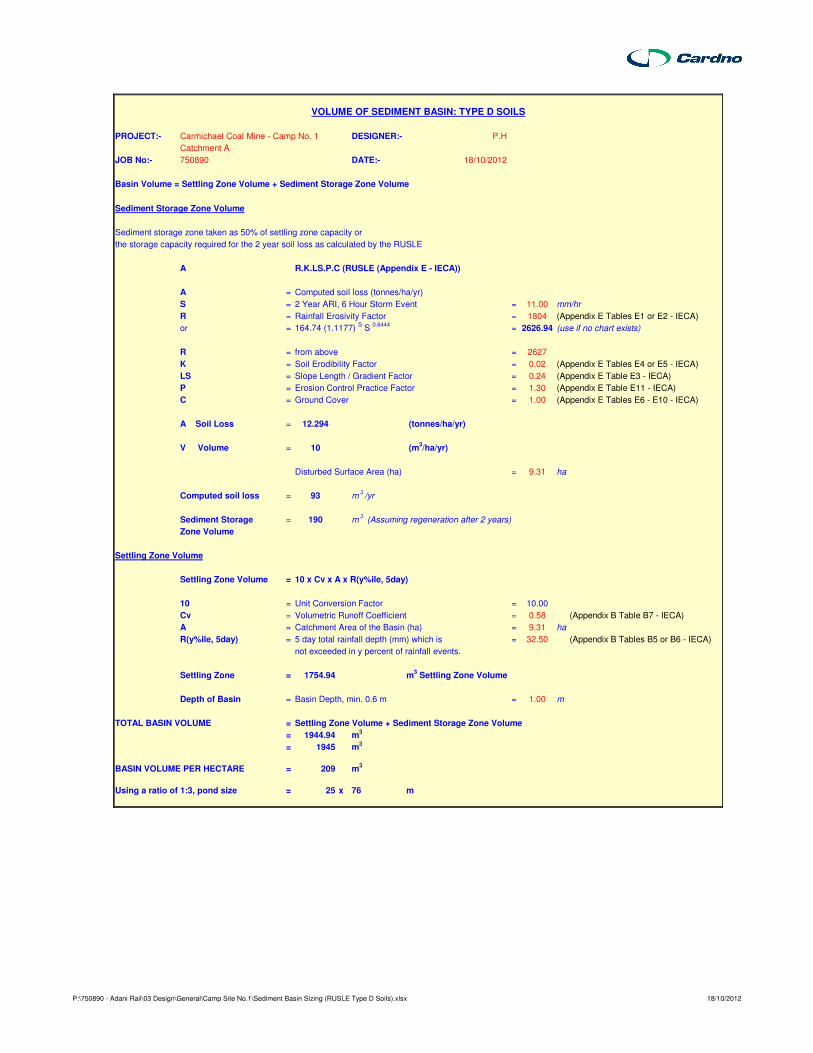
PROJECT:- Carmichael Coal Mine - Camp No. 1 DESIGNER:- P.H
Catchment A
JOB No:- 750890 DATE:- 18/10/2012
Basin Volume = Settling Zone Volume + Sediment Storage Zone Volume
Sediment Storage Zone Volume
Sediment storage zone taken as 50% of settling zone capacity or
the storage capacity required for the 2 year soil loss as calculated by the RUSLE
A R.K.LS.P.C (RUSLE (Appendix E - IECA))
A = Computed soil loss (tonnes/ha/yr)
S = 2 Year ARI, 6 Hour Storm Event = 11.00 mm/hr
R = Rainfall Erosivity Factor = 1804 (Appendix E Tables E1 or E2 - IECA)
or = 164.74 (1.1177) S S
0.6444= 2626.94 (use if no chart exists)
R = from above = 2627
K = Soil Erodibility Factor = 0.02 (Appendix E Tables E4 or E5 - IECA)
LS = Slope Length / Gradient Factor = 0.24 (Appendix E Table E3 - IECA)
P = Erosion Control Practice Factor = 1.30 (Appendix E Table E11 - IECA)
C = Ground Cover = 1.00 (Appendix E Tables E6 - E10 - IECA)
A Soil Loss = 12.294 (tonnes/ha/yr)
V Volume = 10 (m3/ha/yr)
Disturbed Surface Area (ha) = 9.31 ha
Computed soil loss = 93 m3/yr
Sediment Storage = 190 m3 (Assuming regeneration after 2 years)
Zone Volume
Settling Zone Volume
Settling Zone Volume = 10 x Cv x A x R(y%ile, 5day)
10 = Unit Conversion Factor = 10.00
Cv = Volumetric Runoff Coefficient = 0.58 (Appendix B Table B7 - IECA)
A = Catchment Area of the Basin (ha) = 9.31 ha
R(y%ile, 5day) = 5 day total rainfall depth (mm) which is = 32.50 (Appendix B Tables B5 or B6 - IECA)
not exceeded in y percent of rainfall events.
Settling Zone = 1754.94 m3 Settling Zone Volume
Depth of Basin = Basin Depth, min. 0.6 m = 1.00 m
TOTAL BASIN VOLUME = Settling Zone Volume + Sediment Storage Zone Volume
= 1944.94 m3
= 1945 m3
BASIN VOLUME PER HECTARE = 209 m3
Using a ratio of 1:3, pond size = 25 x 76 m
VOLUME OF SEDIMENT BASIN: TYPE D SOILS
P:\750890 - Adani Rail\03 Design\General\Camp Site No.1\Sediment Basin Sizing (RUSLE Type D Soils).xlsx 18/10/2012

Stormwater Management Strategy Carmichael Coal Mine Rail Construction Camp 1
30/10/2012 Cardno 22
APPENDIX
D WATER QUANTITY CALCULATIONS

Stormwater Detention Calculations
Carmichael Coal Mine
Camp Site No. 1 - 2 year ARI flow
Existing Case
Internal Catchment
Area 9.31 ha
(using QUDM Vol 1. Book 2. Chapter 4.0)
C10 0.66
F2xC10 0.56
C2 0.56
Time of conc 30 mins
Intensity 50.6 mm/hr
Flow 0.73 m3/s
Total Flow 0.73 m3/s
Volume 1321.4 m3
Developed Case
Internal Catchment
Area 9.31 ha
(using QUDM Vol 1. Book 2. Chapter 4.0)
C10 0.75
F2xC10 0.64
C2 0.64
Time of conc 20 mins
Intensity 60.9 mm/hr
Flow 1.00 m3/s
Total Flow 1.00 m3/s
Volume 1204.8 m3
Detention Basin Sizing (preliminary)
Peak inflow 1.00 m3/s
Peak outflow 0.73 m3/s
Volume 1606.44 m3
r 0.27
Required storage volume
Culp Boyd Carroll Basha Maximum
221.36 431.87 234.51 326.61 431.87
Applying peak flow only factor 2
Required volume is - 864 m3.
Assuming a rectangular basin with 1 in 4 side slopes
and maximum depth of 0.5 metres, required surface area is………
Depth
(m)Length (m)
Width
(m)
Area
(m2)
Volume (m3)
0.0 39.2 20.0 783.7
1.0 47.2 20.0 943.7 863.7
Q2
P:\750890 - Adani Rail\03 Design\General\Camp Site No.1\Detention Basins.xls

Stormwater Detention Calculations
Carmichael Coal Mine
Camp Site No. 1 - 5 year ARI flow
Existing Case
Internal Catchment
Area 9.31 ha
(using QUDM Vol 1. Book 2. Chapter 4.0)
C10 0.66
F5xC10 0.63
C5 0.63
Time of conc 30 mins
Intensity 79.5 mm/hr
Flow 1.29 m3/s
Total Flow 1.29 m3/s
Volume 2320.4 m3
Developed Case
Internal Catchment
Area 9.31 ha
(using QUDM Vol 1. Book 2. Chapter 4.0)
C10 0.75
F5xC10 0.71
C5 0.71
Time of conc 20 mins
Intensity 96.5 mm/hr
Flow 1.78 m3/s
Total Flow 1.78 m3/s
Volume 2133.7 m3
Detention Basin Sizing (preliminary)
Peak inflow 1.78 m3/s
Peak outflow 1.29 m3/s
Volume 2844.98 m3
r 0.28
Required storage volume
Culp Boyd Carroll Basha Maximum
404.28 782.44 427.91 593.36 782.44
Applying peak flow only factor 2
Required volume is - 1565 m3.
Assuming a rectangular basin with 1 in 4 side slopesand maximum depth of 1.0 metres, required surface area is………
Depth
(m)Length (m)
Width
(m)
Area
(m2)
Volume (m3)
0.0 92.8 12.0 1113.7
1.0 100.8 20.0 2016.1 1564.9
Q5
P:\750890 - Adani Rail\03 Design\General\Camp Site No.1\Detention Basins.xls

Stormwater Detention Calculations
Carmichael Coal Mine
Camp Site No. 1 - 10 year ARI flow
Existing Case
Internal Catchment
Area 9.31 ha
(using QUDM Vol 1. Book 2. Chapter 4.0)
C10 0.66
F10xC10 0.66
C10 0.66
Time of conc 30 mins
Intensity 88.2 mm/hr
Flow 1.51 m3/s
Total Flow 1.51 m3/s
Volume 2709.8 m3
Developed Case
Internal Catchment
Area 9.31 ha
(using QUDM Vol 1. Book 2. Chapter 4.0)
C10 0.75
F10xC10 0.75
C10 0.75
Time of conc 20 mins
Intensity 107 mm/hr
Flow 2.08 m3/s
Total Flow 2.08 m3/s
Volume 2490.4 m3
Detention Basin Sizing (preliminary)
Peak inflow 2.08 m3/s
Peak outflow 1.51 m3/s
Volume 3320.57 m3
r 0.27
Required storage volume
Culp Boyd Carroll Basha Maximum
470.91 911.88 498.47 691.40 911.88
Applying peak flow only factor 2
Required volume is - 1824 m3.
Assuming a rectangular basin with 1 in 4 side slopesand maximum depth of 1.0 metres, required surface area is………
Depth
(m)Length (m)
Width
(m)
Area
(m2)
Volume (m3)
0.0 109.0 12.0 1307.8
1.0 117.0 20.0 2339.7 1823.8
Q10
P:\750890 - Adani Rail\03 Design\General\Camp Site No.1\Detention Basins.xls

Stormwater Detention Calculations
Carmichael Coal Mine
Camp Site No. 1 - 20 year ARI flow
Existing Case
Internal Catchment
Area 9.31 ha
(using QUDM Vol 1. Book 2. Chapter 4.0)
C10 0.66
F20xC10 0.69
C20 0.69
Time of conc 30 mins
Intensity 100 mm/hr
Flow 1.79 m3/s
Total Flow 1.79 m3/s
Volume 3225.9 m3
Developed Case
Internal Catchment
Area 9.31 ha
(using QUDM Vol 1. Book 2. Chapter 4.0)
C10 0.75
F20xC10 0.79
C20 0.79
Time of conc 20 mins
Intensity 122 mm/hr
Flow 2.48 m3/s
Total Flow 2.48 m3/s
Volume 2981.5 m3
Detention Basin Sizing (preliminary)
Peak inflow 2.48 m3/s
Peak outflow 1.79 m3/s
Volume 3975.37 m3
r 0.28
Required storage volume
Culp Boyd Carroll Basha Maximum
575.13 1107.89 608.43 841.51 1107.89
Applying peak flow only factor 2
Required volume is - 2216 m3.
Assuming a rectangular basin with 1 in 4 side slopesand maximum depth of 1.0 metres, required surface area is………
Depth
(m)Length (m)
Width
(m)
Area
(m2)
Volume (m3)
0.0 133.5 12.0 1601.8
1.0 141.5 20.0 2829.7 2215.8
Q20
P:\750890 - Adani Rail\03 Design\General\Camp Site No.1\Detention Basins.xls

Stormwater Detention Calculations
Carmichael Coal Mine
Camp Site No. 1 - 50 year ARI flow
Existing Case
Internal Catchment
Area 9.31 ha
(using QUDM Vol 1. Book 2. Chapter 4.0)
C10 0.66
F50xC10 0.76
C50 0.76
Time of conc 30 mins
Intensity 116 mm/hr
Flow 2.28 m3/s
Total Flow 2.28 m3/s
Volume 4098.4 m3
Developed Case
Internal Catchment
Area 9.31 ha
(using QUDM Vol 1. Book 2. Chapter 4.0)
C10 0.75
F50xC10 0.86
C50 0.86
Time of conc 20 mins
Intensity 142 mm/hr
Flow 3.17 m3/s
Total Flow 3.17 m3/s
Volume 3800.8 m3
Detention Basin Sizing (preliminary)
Peak inflow 3.17 m3/s
Peak outflow 2.28 m3/s
Volume 5067.74 m3
r 0.28
Required storage volume
Culp Boyd Carroll Basha Maximum
741.90 1424.68 784.58 1083.29 1424.68
Applying peak flow only factor 2
Required volume is - 2849 m3.
Assuming a rectangular basin with 1 in 4 side slopesand maximum depth of 1.0 metres, required surface area is………
Depth
(m)Length (m)
Width
(m)
Area
(m2)
Volume (m3)
0.0 173.1 12.0 2077.0
1.0 181.1 20.0 3621.7 2849.4
Q50
P:\750890 - Adani Rail\03 Design\General\Camp Site No.1\Detention Basins.xls
Stormwater Detention Calculations
Carmichael Coal Mine
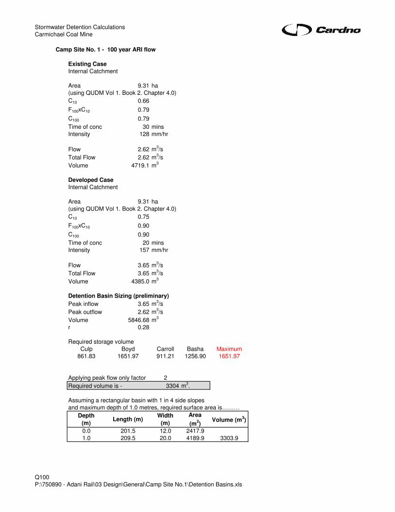
Camp Site No. 1 - 100 year ARI flow
Existing Case
Internal Catchment
Area 9.31 ha
(using QUDM Vol 1. Book 2. Chapter 4.0)
C10 0.66
F100xC10 0.79
C100 0.79
Time of conc 30 mins
Intensity 128 mm/hr
Flow 2.62 m3/s
Total Flow 2.62 m3/s
Volume 4719.1 m3
Developed Case
Internal Catchment
Area 9.31 ha
(using QUDM Vol 1. Book 2. Chapter 4.0)
C10 0.75
F100xC10 0.90
C100 0.90
Time of conc 20 mins
Intensity 157 mm/hr
Flow 3.65 m3/s
Total Flow 3.65 m3/s
Volume 4385.0 m3
Detention Basin Sizing (preliminary)
Peak inflow 3.65 m3/s
Peak outflow 2.62 m3/s
Volume 5846.68 m3
r 0.28
Required storage volume
Culp Boyd Carroll Basha Maximum
861.83 1651.97 911.21 1256.90 1651.97
Applying peak flow only factor 2
Required volume is - 3304 m3.
Assuming a rectangular basin with 1 in 4 side slopes
and maximum depth of 1.0 metres, required surface area is………
Depth
(m)Length (m)
Width
(m)
Area
(m2)
Volume (m3)
0.0 201.5 12.0 2417.9
1.0 209.5 20.0 4189.9 3303.9
Q100
P:\750890 - Adani Rail\03 Design\General\Camp Site No.1\Detention Basins.xls

ELECTRICAL REPORT PREPARED BY CARDNO

Adani Temporary Rail Camps 1, 2, 3 Electrical Load Estimate Prepared for: Cardno Date: 23 October 2012

ELECTRICAL SECTION FOR RAIL CAMP 1, 2, 3 1.0 ELECTRICAL LOAD ESTIMATE
1.1 The Proposed Development The proposed development includes the staged construction of a workers’ accommodation village and includes 405 air conditioned single-bed accommodation units and associated central facilities – including dining halls, recreational facilities and administration – and distributed facilities such as laundries and car parking.
1.2 Occupancy and Operation Occupancy on the site will be variable both throughout the day/week and throughout the year. The exact occupancy of the camp, including the proportional split between shifts, is not yet known and in any case is subject to change over time. For the purposes of maximum demand in this report, the worst case – 100% of workers on day shift returning at 7pm – is assumed. The operation and utilisation of central facilities will also be subject to these bulk worker movements (for example, meal preparation leading up to worker arrival, and food/beverage service after arrival); however these facilities will operate on a more or less continuous basis. 4.3 Typical Accommodation Block Load Estimate The table below is based on the Atco 14.4 x 3.3 three person unit drawing. There will be other types of units installed such as disabled access units however the four person unit will be the typical unit installed.
Accommodation Electrical Load Items Per Unit (Watts) 1 phase
Averaged 3 phase load
per unit (Watts)
Lighting 60
Television 50
Fridge (Westinghouse WRM1300WC) 100
General Power (laptop, phone charger) 100
Hot Water (Rheem 235 Litre heat pump) 250
Air-conditioning (TECO 2.66kW split system) 740
Accommodation Electrical Load Estimate 1,300 1ph 434 3ph
ELECTRICAL SECTION FOR RAIL CAMP 1, 2, 3
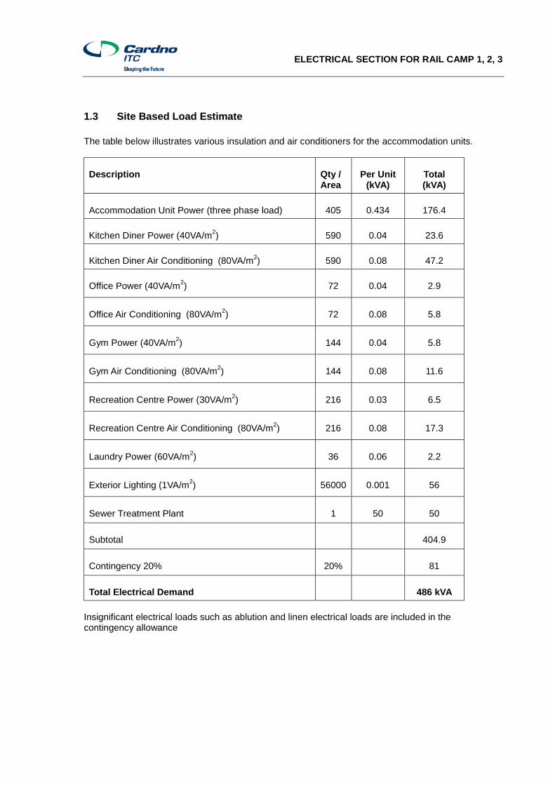
1.3 Site Based Load Estimate The table below illustrates various insulation and air conditioners for the accommodation units.
Description Qty / Area
Per Unit (kVA)
Total (kVA)
Accommodation Unit Power (three phase load) 405 0.434 176.4
Kitchen Diner Power (40VA/m2) 590 0.04 23.6
Kitchen Diner Air Conditioning (80VA/m2) 590 0.08 47.2
Office Power (40VA/m2) 72 0.04 2.9
Office Air Conditioning (80VA/m2) 72 0.08 5.8
Gym Power (40VA/m2) 144 0.04 5.8
Gym Air Conditioning (80VA/m2) 144 0.08 11.6
Recreation Centre Power (30VA/m2) 216 0.03 6.5
Recreation Centre Air Conditioning (80VA/m2) 216 0.08 17.3
Laundry Power (60VA/m2) 36 0.06 2.2
Exterior Lighting (1VA/m2) 56000 0.001 56
Sewer Treatment Plant 1 50 50
Subtotal 404.9
Contingency 20% 20% 81
Total Electrical Demand 486 kVA Insignificant electrical loads such as ablution and linen electrical loads are included in the contingency allowance

ELECTRICAL SECTION FOR RAIL CAMP 1, 2, 3 1.4 Sustainable Options Solar panels can be installed to reduce the daytime electrical loading however a solar system will not however reduce the site’s peak demand which is expected to occur around 6-8pm. As a result this system will reduce daytime diesel usage costs but not generator sizes.
1.5 Generator Recommendation
1.5.1 Investigation / Feasibility The camp will be supplied via onsite diesel generation plant with associated fuel storage. Based on our experience, and advice from colleagues at Power and Water Corporation (Northern Territory), two likely plant suppliers were identified – Cummins and Caterpillar. Of these, it is understood that Cummins have better plant availability and so we have held initial discussions with them. This does not preclude the consideration of Caterpillar or other suppliers at the next stage of design. To serve the site’s maximum demand of 486kVA, a total of two (2) 600kVA 415V generators would be required (one duty, one standby). The larger kVA rating is required as the generators are designed for 0.8 power factor and the anticipated power factor for the mining camp is close to unity. The location of these generators needs to be carefully considered due to the noise and emissions implications of large diesel generation sets.
1.5.2 Fuel Storage The camp will be supplied via onsite diesel generation plant with associated fuel storage. At full load a single Cummins C700 640kVA prime rated generator uses approximately 140 litres of diesel per hour at full load. Based on a six day refuelling schedule a single 20,000L double bunded diesel tank is required to service both generators. Refer to figure 7 below.
Figure 7 – typical self-bunded diesel storage units.

ELECTRICAL SECTION FOR RAIL CAMP 1, 2, 3
1.5.3 Available Capacity and Timeframe The standard lead time for the generators is 12 weeks if there are not units available onshore. The lead time for the 20,000 litre fuel tanks is 12 weeks.
1.5.4 Operation and Maintenance Costs Assuming the generators are loaded on average to 75% of their rated capacity with a fuel usage of 100 litres per hour and an assumed price of diesel at $1.60/litre results in a monthly fuel cost of approximately $115,000/month. The anticipated maintenance cycle for the generators would be 1,000 hours. Assuming approximately 12 hours/day duty, each set would require maintenance every 12 weeks. Oil changes would occur every 4,000 hours or every 11 months per set. Major overhaul of each set would be required every three years. On this basis maintenance costs would be in the order of $40,000 per year.

ELECTRICAL SECTION FOR RAIL CAMP 1, 2, 3 2.0 RECOMMENDATIONS AND CONCLUSION Based on the above, it is recommended that for the purposes of design and supply to the site, a ‘base’ (worst case) maximum demand value of 486kVA be adopted. This value allows for an occupancy of 405 units all on day shift, and further includes a 20% design contingency. It is recommended two generators are installed in a duty / standby arrangement. The recommended generator size is 600kVA with a 20,000 litre double bunded diesel tank to serve both generators on a six day refuelling schedule.


