Download - Ht 3513491354

7/27/2019 Ht 3513491354
http://slidepdf.com/reader/full/ht-3513491354 1/6
Dhanda M et al Int. Journal of Engineering Research and Application www.ijera.com ISSN : 2248-9622, Vol. 3, Issue 5, Sep-Oct 2013, pp.1349-1354
www.ijera.com 1349 | P a g e
An Approach towards Repairing Of Nimonic Alloy Component
through Laser Based Layered Manufacturing Technique
Bansiya S., Dhanda M., Saha P Mechanical Engineering Department, Indian Institute Of Technology Kharagpur-721302, India
AbstractIn this work investigate has been done to identify the possibility of depositing a layer of Ni-Co-Cr powder
mixture over an experimental block of Nimonic 263 alloy material in order to repair it by a 2 kW Ytterbium
fiber laser. The various process parameters have been optimized to obtain the best quality deposition free of
porosity and cracks. An optical microscopic study of the resulting microstructures of the substrate and
deposited layers has been conducted. For further study SEM, analysis have also been carried out. The
microhardness of deposited layer ranged from HV0.05306 to HV0.05331. The hardness decreases gradually from
the top of the deposited layer to the substrate zone. The knowledge achieved in this study would help in takingdecisions with regard to setting the parameters required for subsequent repair a Nimonic component through
layered manufacturing.
Keywords: Laser, Direct Metal Laser Sintering, Nimonic 263, Repair.
I. IntroductionDuring the life of a component it may be
subject to local impacts, corrosion, variable or
regular thermal cycles and stresses, or other testing
conditions with the potential to cause local defects or
cracking. For example, cracks can be initiated in
welds by mismatched creep properties, at geometric
discontinuities in foundry goods on account of
residual thermal stresses, and in turbine shafts and blades owing to high-cycle fatigue and corrosion.
Fatigue and stress cracks are common initiators of
failures that cause high-performance and high-value
components to be discarded as useless. The
development of ultrasonic techniques means that
internal cracks can now be detected before failure
occurs.
In the fields of mechanical engineering,
metallurgical industry and petrochemical and electric
power, a large number of components work in
formidable conditions involving impact, abrasion,
high-temperature and pressure, and are liable to
breakdown. Fig.1 shows a cam which has been wornout and broken due to friction. If successful repairing
cannot be carried out, the damaged components will
have to be discarded and a significant loss will be
caused.
Fig.1: broken and worn out cam
Theoretically, any product that can bemanufactured can be remanufactured. The cost of
remanufactured goods is cheaper than a new part, and
can be remanufactured multiple times, further
extending its life. The ideal products for
remanufacturing are those that are not likely to suffer from obsolescence, and those whose recoverable
value is a high percentage of the price of the new
product. Rebuilt engines, for instance, require only
fifty percent of the energy and sixty-seven percent of
RESEARCH ARTICLE OPEN ACCESS

7/27/2019 Ht 3513491354
http://slidepdf.com/reader/full/ht-3513491354 2/6
Dhanda M et al Int. Journal of Engineering Research and Application www.ijera.com ISSN : 2248-9622, Vol. 3, Issue 5, Sep-Oct 2013, pp.1349-1354
www.ijera.com 1350 | P a g e
the labor needed to produce a new engine. Hence,
remanufacturing should be looked upon as a tool that
can save and reuse resources to eventually boost a
country’s economy.
Conventional repairing methods presently
adopted mainly include mechanical machining, brush-
electroplate, deposited welding, TIG welding andthermal spraying (flame spraying and plasma
spraying). Although, these methods have differentadvantages, there are still many drawbacks, such as
being time-consuming and labor intensive, having
limited thickness of deposition layers and machinable
times, poor bonding strength, large amount of
porosities and cracks, or significant heat injection and
distortion of the substrates. Therefore, it is of greatinterest to develop high-efficiency and precision
repairing technologies that will extend the lifetime of
components. Laser cladding is one of the precision
repairing method which overcome drawbacks of
conventional repairing method. So first laser claddingis discussed and then how it can be used as repairingtool is discussed.
Laser cladding is a novel powerful tool for
the repairing of metal components. Laser cladding is a
relatively new process which is being used in
industrial sectors like petrochemical, aerospace,
machine and dies building, automotive, energy
production to repair damaged high-value machine
components like turbine blades, shafts, motors and to
improve the corrosion and/or wear resistance of
metallic components like tooling, pumps, valves, off-
shore pipes.
The novel versatile laser cladding technologyis such a repairing technology, which integrates laser
technology, CAD/CAM technology, advanced
materials processing technology and photoelectric
measuring and control technology. Different similar
techniques, for example direct light fabrication (DLF)[1], laser engineered net shaping (LENS) and direct
metal deposition [2] have been developed and studied
by many research groups in recent years. Laser
cladding combines the two technologies of rapid
prototyping manufacturing and laser cladding surfacemodification, and can be used to fabricate three-
dimensional fully dense metal components directly
from the CAD model.
Historically, fusion welding has been used
for repair of surface cracks. One of the first methods
is tungsten inert gas (TIG) welding [3]. However,
while relatively easy to apply, this method produces a
lot of heat and can cause high residual stresses,resulting in distortion and heat-related effects in the
base metal [4]. Plasma transferred arc (PTA) welding[5] and electron beam (EB) welding [6] are alternative
processes requiring lower heat input but needing more
complex and expensive apparatus. EB welding, in
particular, gives a very precise heat flux, but it needs a
vacuum environment so is more expensive and
difficult to apply to larger parts [7]. The high-velocityoxyfuel (HVOF) thermal spraying technique [8] is a
procedure that has found use in many industries.
There is less component distortion than with TIG
welding and it has many advantages over plasma
spraying, including deposition of a thicker and lower- porosity coating. However, tight control of depth andspread of deposited material is not possible, meaning
an extensive secondary machining stage is usually
required.
The process of laser direct metal deposition
[9] is well suited to surface repair applications.
LDMD involves creating a moving melt pool on a
metal surface using a laser and blowing metal powder
of the same or a different type into it using an inert
gas stream. The added material increases the size of
the pool, which rapidly solidifies into a raised track
when the laser moves on. The deposition area can
thus be precisely controlled. Residual stresses areformed but are lower than from TIG welding and can
be compressive at the surface [10]. The physical and
corrosion properties of the final material can be
difficult to predict because it undergoes a repeated
heating – cooling cycle [11], but they can in manycases exceed those of the parent material.
II. Experimental Procedures The substrate was Nimonic alloy 263
with a sample size of 20mm x 60mm x 15mm
whose constituents and their percentages were as
follows:
Table 1. Chemical Composition of Nimonic Alloy 263
Component C Al Ti Mo Co Cr Fe Ni
Weight % 0.04-0.08 0.6 1.9-2.4 5.6-6.1 19-21 19-21 0.7 balance
Table 2. Physical Properties of Nimonic Alloy 263
The physical properties of the powder material which was used to deposit a layer over substrate material was
as follows:
Materials Density(g/cm
3)
Melting point(
0C)
Specific Heat(J/kg-
0C)
Hardness
Nimonic Alloy 263 8.36 1355 461 HV 340

7/27/2019 Ht 3513491354
http://slidepdf.com/reader/full/ht-3513491354 3/6
Dhanda M et al Int. Journal of Engineering Research and Application www.ijera.com ISSN : 2248-9622, Vol. 3, Issue 5, Sep-Oct 2013, pp.1349-1354
www.ijera.com 1351 | P a g e
Table 3 Powder Materials Properties
The powder materials are mixed in thefollowing composition:Ni-60% (by weight), Cr-20%
(by weight) and Co-20% (by weight). 4% PVA was
used for sticking purpose. PVA gives excellent
sticking strength up to 250o
C temperature.
A 200 micron thick powder layer was applied on the
substrate surface. Then the substrate was kept infurnace for 150-200
0C for 20 min to dry it.
The experimental setup comprises of a Laser Source
(2 kW Fiber laser machine with NC control laser
head) and a coaxial inert gas supply nozzle with side
inert gas supply attachment. A 2 kW fiber laser basedon Ytterbium operating at 1085nm wave length has
been used. This beam quality was 10 times better
than a standard Nd-YAG laser. This laser was being
used for the experiments. The laser head can be
controlled by main control unit.
Fig. 2.Experimental set up
The prepared sample was laser cladded and laser
power, gas pressure and laser scanning speed were
set as the process parameters. Different values of
these parameters, which were taken, are given below.
Laser power...........................1000 W, 1500 W
Gas pressure...........................1 bar, 1.5 bar
Laser scanningspeed.............1500,1600,1800,2000,2500,3000,3500
mm/min
Total 16 laser tracks were formed by laser cladding by different combinations of parameters which are
summarized as follows:
Table 4: Experiments to optimize process parameters Powders: Ni+Cr+Co (60%+20%+20%) Layer
thickness-200 micron Sticking Agent: 4%PVA; Beam inclination angle = 12o;
Sample
no. with
track
direction
Sample
track no.
P I
(W)
v s
(mm/min)Observations Remarks
← Ni101
(200µm)
1. 1000 3500 Powder blowen away
Y=6.0,Pr=1 bar,Z=-290
2. 1500 3000 Partially deposited
3. 2000 2500 Do
4. 2000 2000
Fully deposited5. 2000 1800
6. 2000 1600
7. 2000 1500
8. 2000 2000 3 overlapY=2.5, Pr=1bar,Z=-290
9. 2000 1800 3 overlap
10. 2000 1600 3 overlap
11. 2000 2000
Fully deposited Y=6.0,Pr=1 bar,Z=-28012. 2000 1800
Name of Powder
Material
Mesh size Density
(g/cc)
Melting Point Temp.
(oC)
Ni 325 8.908 1455
Cr 150-200 7.190 1907
Co 300 8.900 1495
7/27/2019 Ht 3513491354
http://slidepdf.com/reader/full/ht-3513491354 4/6
Dhanda M et al Int. Journal of Engineering Research and Application www.ijera.com ISSN : 2248-9622, Vol. 3, Issue 5, Sep-Oct 2013, pp.1349-1354
www.ijera.com 1352 | P a g e
13. 2000 1600
14. 2000 1600Z=-280, Gas Pr=1.5bar
15. 2000 1800
16. 2000 2000
The powder layer was fully deposited under
the following set of parameter:
Laser power............................1500 W
Gas pressure............................1 bar
Laser scanning
aped................1600, 1800, 2000 mm/min
While with the other set of process
parameters either the powder was blown away or the
layer was partially deposited.
So total three set of parameters were found to be
good for which three overlapping tracks were made
for each set of parameter. These tracks were given
name as track no.8 (scanning speed 2000 mm/min),track no. 9 (scanning speed 1800 mm/min), and track
no. 10 (scanning speed 1600 mm/min), which are
shown in table 6 above. All the characterisationswere carried out on these three samples.
Following the laser cladding, the samples where good
clad tracks are obtained are cut by wire EDM,
polished in grinder polisher machine by using 140
mesh → 600 mesh → 1000 mesh, SiC emery paper
→ diamond paste of 0.25 micron. After polishing thesample was etched with the following reagent:
20 ml HCl(Conc.)+10 ml HNO3(Conc.)+20 ml
Glycerol+10 ml H2O2
The above reagent was used for revealing of microstructure for Ni-Co-Cr alloys [25].
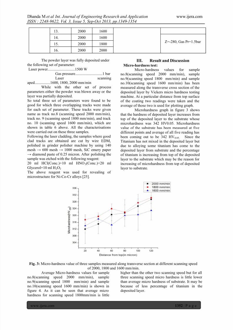
III. Result and DiscussionMicro-hardness test:
Micro-hardness values for sampleno.8(scanning speed 2000 mm/min), sample
no.9(scanning speed 1800 mm/min) and sample
no.10(scanning speed 1600 mm/min) has been
measured along the transverse cross section of the
deposited layer by Vickers micro hardness testingmachine. At a particular distance from top surface
of the coating two readings were taken and the
average of those two is used for plotting graph.
Microhardness graph in figure 3 shows
that the hardness of deposited layer increases fromtop of the deposited layer to the substrate whose
microhardness was 342 HV0.05. Microhardness
value of the substrate has been measured at five
different points and average of all five reading has
been coming out to be 342 HV0.05. Since the
Titanium has not mixed in the deposited layer but
due to alloying some titanium has come to the
deposited layer from substrate and the percentage
of titanium is increasing from top of the deposited
layer to the substrate which may be the reason for
increasing of microhardness from top of deposited
layer to substrate.
Fig. 3: Micro-hardness value of three samples measured along transverse section at different scanning speed
of 2000, 1800 and 1600 mm/min.
Average Micro-hardness values for sampleno.8(scanning speed 2000 mm/min), sample
no.9(scanning speed 1800 mm/min) and sample
no.10(scanning speed 1600 mm/min) is shown in
figure 4. As it can be seen that average microhardness for scanning speed 1800mm/min is little
higher than the other two scanning speed but for allthree scanning speed micro hardness is little lower
than average micro hardness of substrate. It may be
because of less percentage of titanium in the
deposited layer.
7/27/2019 Ht 3513491354
http://slidepdf.com/reader/full/ht-3513491354 5/6
Dhanda M et al Int. Journal of Engineering Research and Application www.ijera.com ISSN : 2248-9622, Vol. 3, Issue 5, Sep-Oct 2013, pp.1349-1354
www.ijera.com 1353 | P a g e
Fig. 4: Average micro hardness of sample 8,
sample 9 and sample 10 with scanning speed of
2000mm/min, 1800mm/min and 1600mm/min
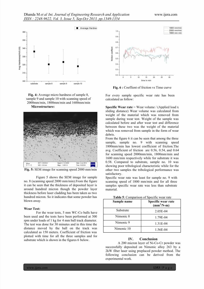
Microstructure:
Fig. 5: SEM image for scanning speed 2000 mm/min
Figure 5 shows the SEM image for sample
no. 8 (scanning speed 2000 mm/min).From the figure
it can be seen that the thickness of deposited layer is
around hundred micron though the powder layer
thickness before laser cladding has been taken as two
hundred micron. So it indicates that some powder has
blown away.
Wear Test:
For the wear tests, 5 mm WC-Co balls have
been used and the tests have been performed at 300
rpm under loads of 1 kg for 4 mm ball track diameter.
The test was done for 30 minutes and in this time the
distance moved by the ball on the track was
calculated as 150 meters. Coefficient of friction was
plotted with time for all the three samples and for substrate which is shown in the figures 6 below.
Fig. 6 : Coeffient of friction vs Time curve
For every sample specific wear rate has been
calculated as follow:
Specific Wear rate = Wear volume / (Applied load x
sliding distance) Wear volume was calculated from
weight of the material which was removed from
sample during wear test. Weight of the sample was
calculated before and after wear test and difference
between these two was the weight of the material
which was removed from sample in the form of wear
debris.From the figure 6 it can be seen that among the three
sample, sample no. 9 with scanning speed
1800mm/min has lowest coefficient of friction.The
avg. Coefficient of friction are 0.56, 0.54, and 0.64for scanning speed 2000mm/min, 1800mm/min and
1600 mm/min respectively while for substrate it was0.58. Compared to substrate, sample no. 10 was
showing poor tribological characteristic while for the
other two samples the tribological performance was
satisfactory.
Specific wear rate was least for sample no. 9 with
scanning speed of 1800 mm/min and for all three
samples specific wear rate was less than substrate
material.
Table 5: Comparison of Specific wear rate
Sample name Specific wear rate(mm
3/N-m)
Substrate 2.05E-04
Nimonic 8 1.79E-04
Nimonic 9 1.31E-04
Nimonic 10 1.56E-04
IV. ConclusionA 200 micron layer of Ni-Co-Cr powder was
successfully deposited on Nimonic alloy 263 by a
2kW fiber laser using preplaced powder method. The
following conclusion can be derived from the
experimental work.

7/27/2019 Ht 3513491354
http://slidepdf.com/reader/full/ht-3513491354 6/6
Dhanda M et al Int. Journal of Engineering Research and Application www.ijera.com ISSN : 2248-9622, Vol. 3, Issue 5, Sep-Oct 2013, pp.1349-1354
www.ijera.com 1354 | P a g e
The thickness of the deposited layer was hundred
microns while the powder layer thickness before
coating was two hundred micron.
The microhardness of deposited layer was
slightly lower than substrate..
Coefficient of friction was higher for substrate
material than other three sample. And among thethree sample, sample no. 9 with scanning speed
1800mm/min has lowest coefficient of friction.
The knowledge achieved in this study would
help in taking decisions in setting the process
parameters required for subsequent repair a
Nimonic component through layered
manufacturing.
References
[1] J. O. Milewski, G. K. Lewis, D. J. Thoma,
G. I. Keel, R. B. Nemec, and R. A. Reinert,“ Directed light fabrication of a solid metal
hemisphere using 5-axis powder deposition,” J. Mater. Process. Technol. 75,
165 – 172 (1998).
[2] J. Mazumder, D. Dutta, N. Kikuchi, and A.
Ghosh, “Closed loop direct metal
deposition — Art to part ,” Opt. Lasers
Eng. 34, 397 – 414 (2000).
[3] Nakata, K., Owashi, M., Koshiwashi, M.,
Hashimoto, T., Anzai, H., Saito, Y., and
Kono, W. Re-weldability of neutron-
irradiated stainless steels studied by multi-
pass TIG welding . J. Nucl. Mater., 2002,
307, 1578 – 1583.
[4] Tusek, J. and Ivancic, R. Computer-aided
analysis of repair welding of stamping tools.
Z. fu¨r Metallkunde, 2004, 95(1), 8 – 13.
[5] Su, C., Chou, C., Wu, B., and Lih, W.
Plasma transferred arc repair welding of the
nickel-base superalloy IN-738LC . J. Mater.
Engg and Performance, 1997, 6(5), 619 –
627.
[6] Henderson, M. B., Arrell, D., Larsson, R.,Heobel, M., and Marchant, G. Nickel based
superalloy welding practices for industrial
gas turbine applications. Sci. and Technol.
Weld. and Joining, 2004, 9(1), 13 – 21.
[7] Taminger, K. M. B. and Hafley, R. A.
Electron beam freeform fabrication: a rapid
metal deposition process. In Proceedings of
3rd Annual Automotive Composites
Conference, Troy, Michigan, 2003, CD-
ROM.
[8] Tan, J. C., Looney, L., and Hashmi, M. S. J.
Component repair using HVOF thermal
spraying. J. Mater . Processing Technol.,
1999, 92 – 93, 203 – 208.
[9] Toyserkani, E. and Khajepour, A. A
mechatronics approach to laser powder
deposition process. Mechatronics, 2006,16(10), 631 – 641.
[10] Grum, J. and Slabe, J. M. A comparison of
tool-repair methods using CO2 laser
surfacing and arc surfacing . Appl. Surf.
Sci., 2003, 208 – 209, 424 – 431.
[11] Pinkerton, A. J., Karadge, M., Syed, W. U.
H., and Li, L. Thermal and microstructural
aspects of the laser direct metal depositionof Waspaloy. J. Laser Applic., 2006, 18(3),
216 – 226.


