Paradigm shift -Growing electrification is leading to a power matrix
Pág 6 Nov 2011 Siemens S.A.Smart Grid Overview
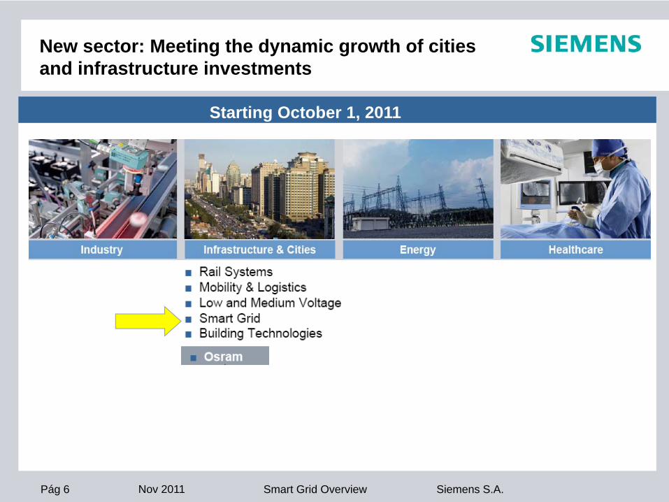
New sector: Meeting the dynamic growth of citiesand infrastructure investments
Starting October 1, 2011
Pág 7 Nov 2011 Siemens S.A.Smart Grid Overview
Smart grid helps managing the challenges of the New Energy Age
Pág 8 Nov 2011 Siemens S.A.Smart Grid Overview
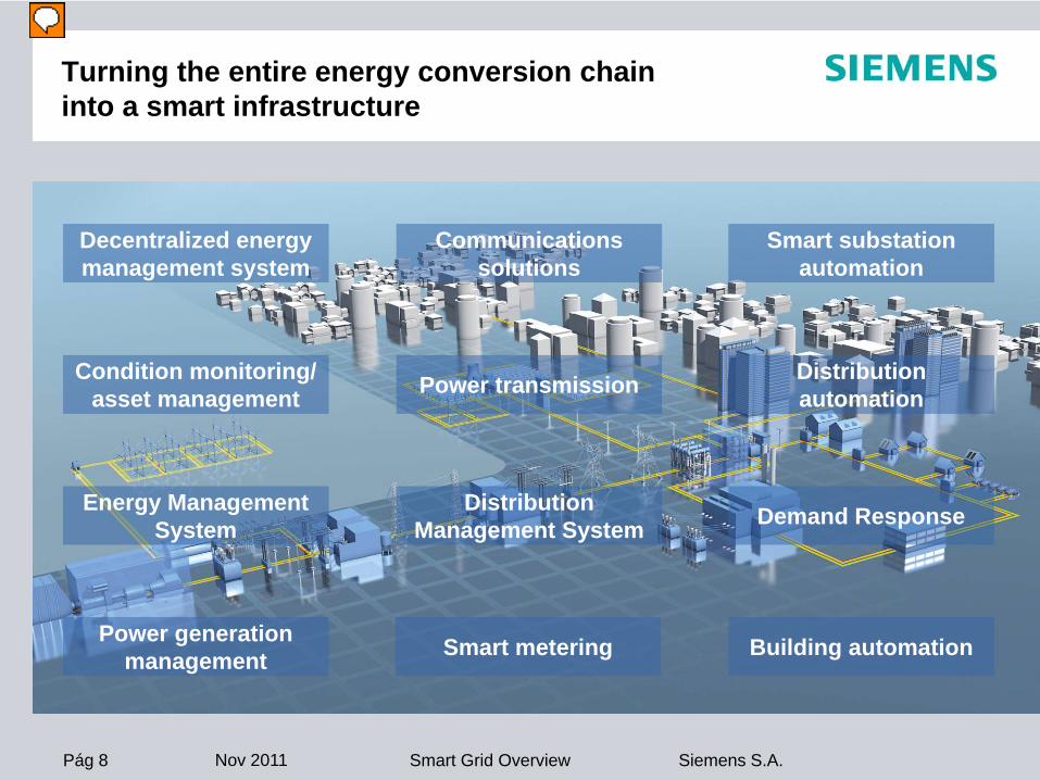
Turning the entire energy conversion chain into a smart infrastructure
Smart metering
Power transmissionCondition monitoring/asset management
Distribution automation
Building automation
Communications solutions
Decentralized energy management system
Smart substation automation
Power generation management
Energy Management System
Distribution Management System Demand Response
Moderador
Notas de la presentación
Convirtiendo toda la cadena de conversión energética en una infraestructura inteligente, siendo necesario para ello cubrir todos los aspectos que se destacan en esta imagen. El resto de la presentación es el desarrollo de cada uno de estos aspectos, empezando por la Generación Térmica, también la Generación Distribuida, siguiendo con el Transporte (Transmission) y la Distribución.
Pág 9 Nov 2011 Siemens S.A.Smart Grid Overview
Improve generation business performance under challenging market requirements
Pág 10 Nov 2011 Siemens S.A.Smart Grid Overview
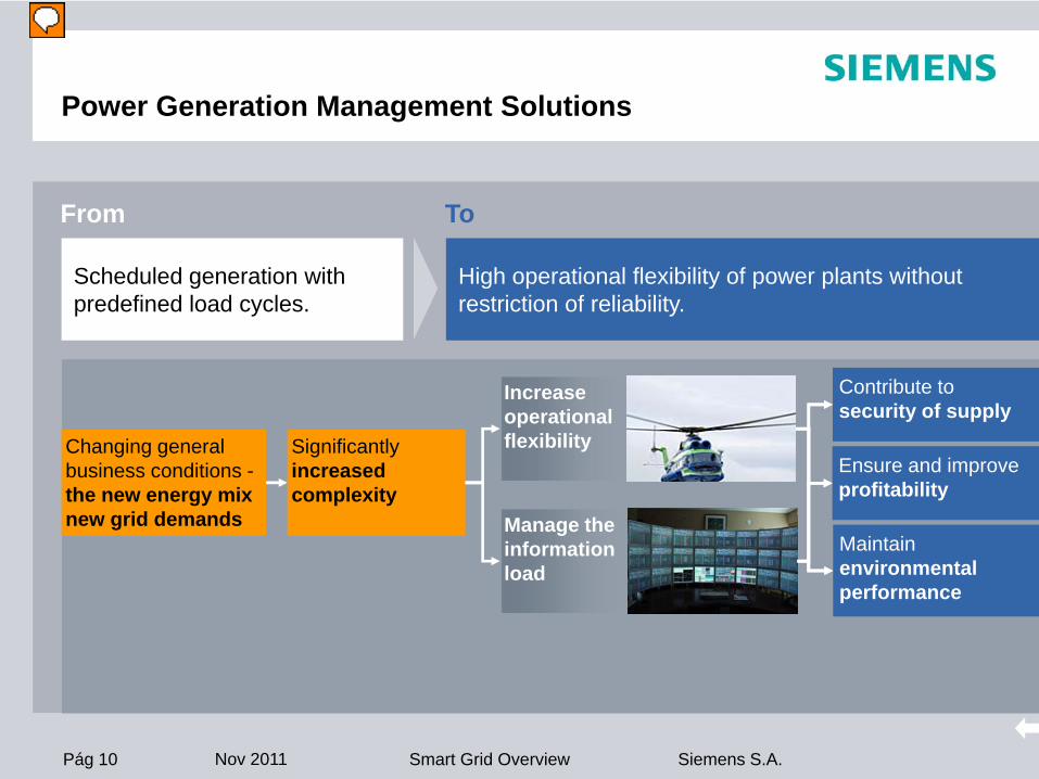
Power Generation Management Solutions
Changing general business conditions -the new energy mixnew grid demands
Significantlyincreased complexity
Increase operational flexibility
Manage the information load
Contribute to security of supply
Ensure and improve profitability
Maintain environmental performance
High operational flexibility of power plants without restriction of reliability.
Scheduled generation with predefined load cycles.
From To
Moderador
Notas de la presentación
Los cambios de las condiciones de mercado (nuevo mix que provoca nuevas necesidades en la red), provoca como consecuencia una aumento enla complejidad que se plasma en dos necesidades: el incremento de flexibilidad y la gestión de la información que si se cubren ayudarían a alcanzar el triple objetivo de seguridad, rentabilidad y respeto al medioambiente.
Pág 11 Nov 2011 Siemens S.A.Smart Grid Overview
EnterpriseResourcePlanning
Control System
Fuels Managem.
InformationManagem.
UnitDispatch
Diagnostics ConditionMonitoring
EmissionsMonitoring
GenerationManagem.
Process Optimi-zation
Power Generation Management
SPPA-M3000Energy Management Suite
Manage data load from grid and plant to provide relevant and reliable decision-making information
Moderador
Notas de la presentación
Esta es la solución Siemens a los requisitos anteriormente planteados. Permite la gestión de carga de datos desde la red a la planta y viceversa para proveer información relevante y segura para poder tomar las mejores decisiones.
Pág 12 Nov 2011 Siemens S.A.Smart Grid Overview
Transmission solutions for secure, sustainable, and efficient power supply
Pág 13 Nov 2011 Siemens S.A.Smart Grid Overview
European Power Grid has reached its limits
Pág 14 Nov 2011 Siemens S.A.Smart Grid Overview
HVDC and FACTS
From To
Security, sustainability, and efficiency of power supply
Congestion, bottlenecks, and blackouts
What’s necessary:Control of power flow Avoidance loop flows and overloadsSystem interconnections with HVDC (Firewall)Use of integrated AC/DC systems with FACTS & HVDCSupport of voltage recovery after system faultsReduction in Transmission losses (HVDC)Use of bulk power energy highways with HVDC & FACTS
Moderador
Notas de la presentación
Pág 15 Nov 2011 Siemens S.A.Smart Grid Overview
Customer Red Eléctrica de España (REE)
Locations Santa Ponça (Mallorca)Morvedre (Sagunto - Valencia)
Status Project in executionPlanned to be working on Jan’12
Technology HVDC Long Submarine Transmission
Power Rating 2 x 200 MW / ± 250 kV DC
Distance Approx. 250 Km.
Benefits for society
Environmental - Reduction in CO2:
1.2 million tons p.a. (52 %)
by using Energy-Mix from the Mainland versus local Supply with a
new Oil-fired Power Plant on the Island(Based on International Energy Agency information)
Energy Transmission Network without losses:
Sustainability in Transmission
Customer Inelfe (RTE and REE)
Locations Baixas (France)Santa Llogaia (Spain)
Status Project will start on Jan’11Planned to be working on Dec’13
Technology HVDC PLUS Underground cable
Power Rating 2 x 1000 MW / ± 320 kV DC
Distance Approx. 60 Km.
HVDC PLUS a Siemens InnovationTechnology Innovation:
Space Saving
by using HVDC PLUS and VSC Technology, system compact and adaptable station in
fields where shortage of space is a criterion.
Cometa
INEL
FE
E T PS (Power Transmission Solutions)HVDC Project “Cometa” and HVDC Plus “Inelfe”
Pág 16 Nov 2011 Siemens S.A.Smart Grid Overview
Transmission solutions for secure, sustainable, and efficient power supply
Pág 17 Nov 2011 Siemens S.A.Smart Grid Overview
Why EMS ?
Innovative Voltage Stability Analysis (VSA)
Energy management system ensures1. reliability of supply2. efficiency in using generation resources under more stringent environmental
restrictions 3. reduction of transmission losses
Alert the operator right in advance before critical situations can occur.
Intelligent Alarm Processors (IAP)
Reduce critical time needed for analyzing faults in the grid and finding the correct alleviating response.
Optimal Power Flow (OPF)Increase grid reliability
Week-/Day-Ahead Unit Commitment/Hydro Scheduling,Security Constrained Unit Commitment
Balance generating units with consumption in consideration of the capacity of the transmission network.
Moderador
Notas de la presentación
The Siemens Spectrum Power Energy Management System (EMS) balances generating units with consumption in consideration of the capacity of the transmission network. Intelligent Alarm Processors (IAP) reduce the critical time needed for analyzing faults in the grid and finding the correct alleviating response. Innovative Voltage Stability Analysis (VSA) applications, running automatically and independently, alert the operator right in advance before critical situations can occur. Increasing grid reliability is completed by Optimal Power Flow (OPF) applications, continuously striving to keep the system voltage at a high level and eliminate any invalid voltage conditions -control measures determined can be automatically put in place in a closed-loop-control fashion.
Pág 18 Nov 2011 Siemens S.A.Smart Grid Overview
Communications solutions that provide the basis for smart applications
Pág 19 Nov 2011 Siemens S.A.Smart Grid Overview
Communication network solutions
From To
Homogeneous Smart Grid communication network with IP/ Ethernet connectivity between all components
Heterogeneous communication networks limited in capacity and bandwidth
What’s necessary?Sufficient bandwidth from end to endIP/Ethernet capable devicesFlexible backbone and access communication network solutionNetwork extension down to RMUs and consumersInterfaces and protocols based on energy industry standards
Moderador
Notas de la presentación
Today, most Power utilities are operating heterogenious Communication networks with gaps in Capacity and Bandwidth Typical restrictions are: - Limited bandwidth for new Smart Grid Applications - Communication gaps (missing optical groundwire) within the Energy Network - Unmanaged ringman units due to missing or limited Distribution Communication networks - Various and often proprietary communication interfaces and protocols Future: The network will evolve to a homogeneous Smart Grid Communication network based on: - Sufficient communication bandwidth end to end - Most devices are connected via IP/Ethernet interfaces to the network - Flexible Backbone- and Access Communication Network solution integrating� legacy and Ethernet devices - Most RMU’s are connected to a Communication infrastucture, which is adapted to landscape restrictions (e.g. wireline or wireless solutions) - The Ethernet & IP components are in line with the Standards of the Energy Industry
Pág 20 Nov 2011 Siemens S.A.Smart Grid Overview
Communication network solutions for a Smart GridReference examples
IP solutionsSDH/PDH solutionsPower line carrier and teleprotection equipmentWireless solutionsOptimized solutions for medium and low-voltage applicationsLive Line Installation
More than 50,000 communicationsystems sold
First installation of a Siemens power line carrier system in 1929
Moderador
Notas de la presentación
Siemens is offering Communication systems optimized for Power utilities since more than 80 years. We installed the first Powerline Carrier in 1929. In the meantime we sold more than 50.000 Communication systems in the Energy sector. The slide shows a selection of our customers.
Pág 21 Nov 2011 Siemens S.A.Smart Grid Overview
Streamlined processes for improved, flexible workflow and reliable substation management
Pág 22 Nov 2011 Siemens S.A.Smart Grid Overview
Smart substation automation
Substation automation
What’s necessary?Standard intelligent process interfaces (Process bus IEC 61850)Standard communication and processes inside the station and among stations (horizontal and vertical integration)Digital system, online information, and intelligent applications DDigital protection devices and components for online network analyses
Complex, personal intensive engineering and operating
From To
Moderador
Notas de la presentación
Under the increasing cost saving pressure not only hardware has to be optimized, also the related engineering and maintenance processes must be optimized. Today‘s situation is dominated by a complex, personal intensive engineering and operating workflow. To reach a real Smart Substation Automation it‘s necessary to have Standard intelligent process interfaces (Process bus IEC 61850) Standard communication and processes inside and out of the station (horizontal and vertical integration) Digital system, online information and intelligent applications
Pág 23 Nov 2011 Siemens S.A.Smart Grid Overview
Integrated solutions for highest economic efficiency
Pág 24 Nov 2011 Siemens S.A.Smart Grid Overview
Condition monitoring and asset management
Current transmission and distribution situation
Condition monitoring for better asset performance and grid asset management for advanced asset management
ISCM – Integrated Substation ConditionMonitoring
Information on the ageing or health condition of primary devices in operationProvided by special sensors and/or derived from data typically availableUsing your familiar RTU, communication, and HMI structure
GAMS – Grid Asset Management SuiteBalancing economic and technical aspects for an efficient grid management approach360° view for optimization of asset managementNew maintenance and investment strategies
Primary equipment condition not well known and not integrated in overall grid asset management strategy
From To
Aging infrastructure
Profit as business
model
Decreasing revenue stream
Regulatory & transparency requirements
Transmission bottlenecks
Extreme pressure on
costs
Moderador
Notas de la presentación
Please use the following explanation and or further Information contact: Overall: An integral solution is required to manage the aging infrastructure. Also, we have to bring the technical and financial world of assets together. The question behind is: How can I go to a preventive and Return of capital optimized maintenance model? "Grid Asset management" – GAMS satisfies that demand. It starts at the planning of the grid and reaches to its development and extension. Also it reaches up to the maintenance or the partial or complete renewal of the technical equipment. We have to balance in an intelligent way between technical feasibility of upgrades and capital efficiency of the distribution network. Also, the Utilities market is characterized by less financial resources for improvements and implementation of automatic running processes to maximize the return of invest. Definition: Condition Monitoring is any kind of system or service giving an information on the ageing or health condition of a primary device in operation, derived from special sensor and/or from data typically available. In Scope: Monitoring of primary assets including BoP (balance of plant) inspections Special sensor data Data typically available from control&protection devices (I, U, t) Out of Scope: Protection functions (CM not for tripping) Monitoring of grid load flow condition e.g. for blackout prevention Who are the potential customers? grid operators and grid owners Customer needs in focus Extended lifetime Asset protection Reduced maintenance costs Transmission capacity increase Congestion (Engpass) Management Increased reliability Outage avoidance (in correlation with blackout prevention) Verification of risk management (responsible custodianship) Early warning for damages caused by abnormal weather conditions e.g. OHL icing Further contact: ISCM: M. Schuler, N. Kaiser GAMS: T. Glückselig
Pág 25 Nov 2011 Siemens S.A.Smart Grid Overview
Seamless integration of energy resources into the grid
Pág 26 Nov 2011 Siemens S.A.Smart Grid Overview
Integration of distributed energy resources (DER) and storage by virtual power plants
Distributed energy resources and storage
Virtual power plants – main features:Energy management system for monitoring, planning, and optimization of DERForecasting system for load and generation of wind power and photovoltaic plantsEnergy data management for collection and retrieval of required information, e.g., loads, contractual dataFront-end for communication with distributed power units
Central generation, decentralized consumption
From To
Moderador
Notas de la presentación
Please use the following explanation and or further Information contact: In the recent past, the discussions about energy technology and energy economics have gathered momentum. There are several reasons for that: Due to the rapid economical progress in countries like China or India, the world wide energy consumption growths in parallel. For example, China installed more than 100 GW electrical generation capacities in 2006. In the last time, the prices on the energy markets have increased. For example, in the Europe Union, the electricity prices for households and industry rose in total by 9% and 31 % respectively between January 2000 and January 2006 (figures for the EU15 countries). At least with the IPPC reports (Intergovernmental Panel on Climate Change) published in the beginning of 2007, there is a common understanding that the global warming is caused by mankind. One major factor is the emission of carbon dioxide, which is mainly produced by generating electricity with fossil energy. The consequences of the global warming are so serious, that a world-wide reduction of the carbon dioxide emission is urgently needed. Triggered by the liberalisation of the energy markets in some regions of the world, the operation of the electrical grids have changed. For example, the grids within the UCTE (Union for the Coordination of Transmission of Electricity) were designed for a regional power adequacy. But do to the increasing trades with electricity, extensive cross-border energy transits have become daily business in transmission system operation. �In a Smart Grid, the grid operator has active customers who are the consumers as well as the producers using decentralized generators. Therefore, the decentralized generation of electrical power, heat and cold energy becomes more and more important. The generation of these types of energy nearby the consumers offers economical and ecological benefits. It is assumed that the portion of decentralized generation will increase in the future. The Wuppertal Institute for Climate, Environment and Energy states in a study that the portion in Germany will increase significantly and will reach 45% in the generation mix for electrical energy until 2050. Worldwide, similar trends can be recognized. For example, China plans to increase the portion of the renewable energy up to 10 % until 2010. To reach this target, China has developed a national strategy for renewable energies and will invest more than 50 Billion US Dollars together with other investors. The ecological and economical impact of decentralized generation can be sustainable improved by setting up so-called Virtual Power Plants. A Virtual Power Plant is a collection of small and very small decentralized generation units and flexible loads, which are connected by a communication network and monitored and controlled by a superordinated energy management system. In particular, the following generation techniques are of a special interest for Virtual Power Plants: Biomass power plants Photovoltaic Fuel cells Cogeneration of heating or cooling energy and electrical power in block-type power plants or micro-turbines Wind power plants Small hydro power plants Biomass can be used for energy generation in different ways. Traditionally, wood is used for firing. Due to the high prices for oil and gas, wood has a renaissance for firing in stoves with pellets. More interesting for Virtual Power Plants are chemical processes, which produce synthetic fuels from biomass, e.g. methyl and ethyl alcohol, biogas or synthesis gas. These fuels can be stored and used in gas engines or micro turbines, methyl alcohol can be used in fuel cells. In the past, the power output of decentralized generation like block-type power plants was in the range of some hundreds kW to one MW electrical output and some hundred kW thermal. In the meantime, we see a trend towards small block-type power plants which are designed for supplying smaller buildings. They use gas engines, stirling engines or micro turbines. Currently, field tests are performed with small fuel cells for supplying one-family houses. These types of micro block-type units are mainly designed for generating heating or cooling energy. The generation of electrical energy is a welcome secondary effect. The thermal output of the units is between 10 and 20 kW and the electrical output is up to 5 kW. All of these generating units have one big advantage: The total efficiency factor can exceed 80 % if heating and cooling energy is produced simultaneously with electrical power. This helps to reduce the cost for energy supply and to reach environmental targets, e.g. the reduction of carbon dioxide. By setting up virtual power plants, this advantage can be used to increase the overall energy efficiency of a power system. Up to now, not many Virtual Power Plants are installed. The existing installations are mainly based on large power units. This means that there are only some units, which are connected with conventional remote terminal units (RTU) to the energy management systems. With the increasing installations of smaller units, the structure of Virtual Power Plants will change: the number of units will increase and the communication has to become simpler and much cheaper. By using small CHP (Combined Heat and Power) units, Virtual Power Plants will encompass several hundreds of these generation units.
Pág 27 Nov 2011 Siemens S.A.Smart Grid Overview
Distributed Energy Resources (DER) and storage: Reference example of DEMS
Virtual power plant KonWerl (Germany)
Energy forecastsForecast of regenerative productionCost-optimal planning and management of distributed generationConsideration of topological restrictions in the grid management
Analysis and assessment of individual energy purchase and sales contracts
Moderador
Notas de la presentación
KonWerl is a demonstration project started early in year 2001. The purpose was to demonstrate the technical feasability of the DEMS ICT solution itself with a great variety of process connection channels. The system is still online today and is used as "advertising" and "training" object with respect to decentralized generation and according EMS solutions.
Pág 28 Nov 2011 Siemens S.A.Smart Grid Overview
Pág 29 Nov 2011 Siemens S.A.Smart Grid Overview
Load follows generation, while renewable energy resources are used with maximum benefit
Demand Response
Demand Response:Balancing of generation and consumption through active load managementIntegration of renewablesMaximum use of CO2 free energyMitigation of „negative“ impacts on the grid through load shifting and peak demand shavingIntegration of new loads like electric cars into the network operationOptimization of system operation costs
Generation follows load
From To
For traditional energy systems there is always sufficient controllable supply
And uncontrollable consumption
And the consumption needs to be flexible
Renewable supply capacity is uncontrollable - Storage and energy Management become key to network balancing
Available supply
Peak Demand
Customer Demand Customer Demand
Available supply
Demand
Supply
Moderador
Notas de la presentación
Please use the following explanation and or further Information contact: In the recent past, the discussions about energy technology and energy economics have gathered momentum. There are several reasons for that: Due to the rapid economical progress in countries like China or India, the world wide energy consumption growths in parallel. For example, China installed more than 100 GW electrical generation capacities in 2006. In the last time, the prices on the energy markets have increased. For example, in the Europe Union, the electricity prices for households and industry rose in total by 9% and 31 % respectively between January 2000 and January 2006 (figures for the EU15 countries). At least with the IPPC reports (Intergovernmental Panel on Climate Change) published in the beginning of 2007, there is a common understanding that the global warming is caused by mankind. One major factor is the emission of carbon dioxide, which is mainly produced by generating electricity with fossil energy. The consequences of the global warming are so serious, that a world-wide reduction of the carbon dioxide emission is urgently needed. Triggered by the liberalisation of the energy markets in some regions of the world, the operation of the electrical grids have changed. For example, the grids within the UCTE (Union for the Coordination of Transmission of Electricity) were designed for a regional power adequacy. But do to the increasing trades with electricity, extensive cross-border energy transits have become daily business in transmission system operation. �In a Smart Grid, the grid operator has active customers who are the consumers as well as the producers using decentralized generators. Therefore, the decentralized generation of electrical power, heat and cold energy becomes more and more important. The generation of these types of energy nearby the consumers offers economical and ecological benefits. It is assumed that the portion of decentralized generation will increase in the future. The Wuppertal Institute for Climate, Environment and Energy states in a study that the portion in Germany will increase significantly and will reach 45% in the generation mix for electrical energy until 2050. Worldwide, similar trends can be recognized. For example, China plans to increase the portion of the renewable energy up to 10 % until 2010. To reach this target, China has developed a national strategy for renewable energies and will invest more than 50 Billion US Dollars together with other investors. The ecological and economical impact of decentralized generation can be sustainable improved by setting up so-called Virtual Power Plants. A Virtual Power Plant is a collection of small and very small decentralized generation units and flexible loads, which are connected by a communication network and monitored and controlled by a superordinated energy management system. In particular, the following generation techniques are of a special interest for Virtual Power Plants: Biomass power plants Photovoltaic Fuel cells Cogeneration of heating or cooling energy and electrical power in block-type power plants or micro-turbines Wind power plants Small hydro power plants Biomass can be used for energy generation in different ways. Traditionally, wood is used for firing. Due to the high prices for oil and gas, wood has a renaissance for firing in stoves with pellets. More interesting for Virtual Power Plants are chemical processes, which produce synthetic fuels from biomass, e.g. methyl and ethyl alcohol, biogas or synthesis gas. These fuels can be stored and used in gas engines or micro turbines, methyl alcohol can be used in fuel cells. In the past, the power output of decentralized generation like block-type power plants was in the range of some hundreds kW to one MW electrical output and some hundred kW thermal. In the meantime, we see a trend towards small block-type power plants which are designed for supplying smaller buildings. They use gas engines, stirling engines or micro turbines. Currently, field tests are performed with small fuel cells for supplying one-family houses. These types of micro block-type units are mainly designed for generating heating or cooling energy. The generation of electrical energy is a welcome secondary effect. The thermal output of the units is between 10 and 20 kW and the electrical output is up to 5 kW. All of these generating units have one big advantage: The total efficiency factor can exceed 80 % if heating and cooling energy is produced simultaneously with electrical power. This helps to reduce the cost for energy supply and to reach environmental targets, e.g. the reduction of carbon dioxide. By setting up virtual power plants, this advantage can be used to increase the overall energy efficiency of a power system. Up to now, not many Virtual Power Plants are installed. The existing installations are mainly based on large power units. This means that there are only some units, which are connected with conventional remote terminal units (RTU) to the energy management systems. With the increasing installations of smaller units, the structure of Virtual Power Plants will change: the number of units will increase and the communication has to become simpler and much cheaper. By using small CHP (Combined Heat and Power) units, Virtual Power Plants will encompass several hundreds of these generation units.
Pág 30 Nov 2011 Siemens S.A.Smart Grid Overview
Smart management of electric distribution grids
Pág 31 Nov 2011 Siemens S.A.Smart Grid Overview
Distribution Management
From To
Automation of distribution substations
Communication in distribution networks
Decentralized, intelligent application
Self-healing capabilities
Online condition monitoring
No monitoring, control and automation
No communication
No auxiliary power supply and motor-operated mechanism
No active integration in control Center (manual updates)
Pág 32 Nov 2011 Siemens S.A.Smart Grid Overview
Spectrum Power
GeospatialInformation
System
Database
SpectrumPower
Map-Portal
Disturbance Information
GeographicalInformation
Maps onrequest
Web-System
Our Solution Spectrum Power DMS
Enables a smart, self-healing grid.
Google
Moderador
Notas de la presentación
Today's distribution grid operation is mainly characterized by manual procedures relying �on the experience of an aging work force.
Pág 33 Nov 2011 Siemens S.A.Smart Grid Overview
Flexible and reliable distribution automation
Pág 34 Nov 2011 Siemens S.A.Smart Grid Overview
Distribution automation characteristics
Today’s standard Evolution Smart distributionautomation
No monitoring, control, and automation
No communication
No auxiliary power supply and motor-operated mechanism
No active integration in control center (manual updates)
Automation of distribution substations
Communication in distribution networks
Decentralized, intelligent application
Distribution management system
Harmonized networks and tasks
Self-healing automation functions
Intelligent applications
Online information (operational and non-op.), e.g., power quality system
Moderador
Notas de la presentación
Please use the following explanation and or further Information contact: Today's standards are characterized by a central intelligent Control System and connected to more or less pure periphery data samplers. The intelligence off the grid is mainly in the Control System and all changes in the network infrastructure have to be manually add. Distribution networks information normally only manually updated, therefore no online-data are available only status information. At lower voltage levels the possibilities for communication are very limited. At least the strategic Ring Main Units and Poletops should be implemented within the communication structure. With a more distributed intelligence you have independent working structures with the trend to self-healing applications. Self-healing automation functions Intelligent applications Online information (operational and non-op.) e.g. Power Quality System
Pág 35 Nov 2011 Siemens S.A.Smart Grid Overview
Infusing intelligence into the last mile
Pág 36 Nov 2011 Siemens S.A.Smart Grid Overview
Smart metering
AMISAutomated Metering and Information System
+EnergyIPMeter Data Management System
Smart metering and load managementUnmanaged “take-it-as-it-comes” consumption
From To
Moderador
Notas de la presentación
For further information contact: Wolfgang Bauer Siemens Austria Monika SturmSiemens Austria The until now unmanaged and not transparent consumption is integrated into the distribution network management due to smart metering and load management. The Smart Metering complete solution by Siemens covers the metering and automation infrastructure (AMIS) as well as the meter data Management system (EnergyIP).
Pág 37 Nov 2011 Siemens S.A.Smart Grid Overview
Smart metering characteristics
Monthly meter reading – higher transparency
Flexible tariffs
Increased efficiency of metering business
High-volume, multi-purpose data platform for real-time and offline data service
Chance for additional services
Platform for the “energy efficiency directive”
Fulfillment of legal requirements
Equal legal access provided to all market participants at required access rates
With regard to your customer
With regard toyour business
With regard tolegal aspects
Smart metering and load management
Moderador
Notas de la presentación
Distribution network operators seeking to ensure economical success and expand further under these framework conditions must optimize existing network operation processes and develop new fields of business. The Smart Metering solution by Siemens provides the ideal conditions for doing so. It combines metering and management of distribution networks in one system and was developed explicitly for the special requirements of the liberalized energy market. As a complete solution, the system acquires data and information of households, special contract customers and the distribution network infrastructure and transmits them to a control center. This allows network distribution operators to optimize essential key processes and offer new services and data to their customers, both on the supplier as well as the consumer side. The Smart Metering solution by Siemens is the basis for Smart Grid solutions.
Pág 38 Nov 2011 Siemens S.A.Smart Grid Overview
Making buildings part of the Smart Grid
Pág 39 Nov 2011 Siemens S.A.Smart Grid Overview
Integration of automated buildings into the Smart Grid
Our building managementsolutions and servicesare ready to
communicate with the Smart Grid, improve forecastingand enable variable tariffs and net schedules
enable optimized building performancethrough
optimal scheduling of power generation and loads in buildingsoptimal energy efficiency and sustainabilitymaximum productivity of occupants and building related processesreduction of operational costs
Moderador
Notas de la presentación
The main reason for installing a building management system (BMS) is to ensure maximum comfort for the occupants (or a perfect process conditions) while minimizing the operational costs (energy consumption, equipment maintenance and replacement, alarm handling etc.). �BMS control all major energy relevant devices within buildings:� Heating, ventilation and air-conditioning equipment (HVAC) Integrated room automation (window opener, blinds, lighting etc.) Water and power systems Distributed electricity Generation (photo voltaic, combined heat �and power plants (CHP), wind etc.) In future, our BMS may also take control of energy storage devices �(e.g. electric cars) In addition to that, our BMS solutions always come along with sound sub-metering solutions, which not only support intelligent automation, but also enable building operators to make informed decisions and continuously optimize their building’s performance. In combination with smart metering solutions and/or direct communication with a smart grid management station, a BMS may actively participate in the grid by controlling a building’s energy profile.