CINEMA DSP DOLBYD I G I T A L
D I G I T A L
S U R R O U N D
– +
ON OFF5 54 4
3 3
2 21 1
0
+– 5 54 4
3 3
2 21 1
0
+– 5 54 4
3 3
2 21 1
0
RL
VCR 2 CDVCR 1 TUNER
CBL/SAT TAPED-TV MD
LD DVD
PHONOVCR 3VIDEO AUX
PHONES BASS TREBLE
NATURAL SOUND AV AMPLIFIER DSP-AX1
INPUT MODE
INPUT SELECTOR
VOLUME
S VIDEO VIDEO L RAUDIO
VIDEO AUXBALANCE REC OUT/ZONE 2SOURCE/REMOTE
BASSEXTENSION
PROCESSORDIRECT
STANDBY/ON
6CH IMPUTSET MENU NEXT EFFECT PROGRAMSPEAKERSA B
TRANSMIT RE-NAME CLEARMACRO
MACROLEARN OFF ON
SYSTEMPOWER STANDBY V-AUX TAPE PHONO
D-TV CBL/SAT TUNER MD CD
VCR 1 VCR 2 VCR 3 LD DVD
6CH INPUT
TITLE
ENTER
MENU SOUNDDISPLAY
SOURCE
SELECT SEARCH CHAPTER
%
! !$
* #
$
%
%%%
%
10KEY DSP HALL 1 HALL 2 CHURCH JAZZ CLUB
ROCKCONCERT
ENTER-TAINMENT
CONCERTVIDEO 2
CONCERTVIDEO 1
POWER REC STOP PAUSE PLAY
EX/ESTV
THEATERMOVIE
THEATER 2MOVIE
THEATER 1 /DTS
SUR.
0 +10 +100
1 2 3 4
5 6 7 8
9 10 11 12
+ + +TV VOL
A / B / C / D / E PRESET
TV INPUT
TV MUTE
CH
DISC
MUTE
EFFECT
VOLUME
+–
/
CHP/INDEX
– – –
DSP-AX1Natural Sound AV AmplifierAmplificateur Audio-Video
BG
OWNER’S MANUALMODE D’EMPLOI
BEDIENUNGSANLEITUNG

I
CAUTION: READ THIS BEFORE OPERATING YOUR UNIT.
1. To assure the finest performance, please read this manualcarefully. Keep it in a safe place for future reference.
2. Install this unit in a cool, dry, clean place – away fromwindows, heat sources, sources of excessive vibration,dust, moisture and cold. Avoid sources of humming(transformers, motors). To prevent fire or electrical shock,do not expose the unit to rain or water.
3. Never open the cabinet. If something drops into the set,contact your dealer.
4. Do not use force on switches, controls or connectionwires. When moving the unit, first disconnect the powerplug and the wires connected to other equipment. Neverpull the wires themselves.
5. The openings on the cover assure proper ventilation of theunit. If these openings are obstructed, the temperatureinside the unit will rise rapidly. Therefore, avoid placingobjects against these openings, and install the unit in awell-ventilated area to prevent fire and damage.
(For Europe, UK, and China Models)Be sure to allow a space of at least 10 cm behind, 10 cmon both sides and 30 cm above the top panel of the unit toprevent fire and damage.
6. The voltage used must be the same as that specified on thisunit. Using this unit with a higher voltage than specified isdangerous and may result in fire or other accidents.YAMAHA will not be held responsible for any damageresulting from the use of this unit with a voltage other thanthat specified.
7. Digital signals generated by this unit may interfere withother equipment such as tuners, receivers and TVs. Movethis unit farther away from such equipment if interferenceis observed.
8. Do not attempt to clean the unit with chemical solvents;this might damage the finish. Use a clean, dry cloth.
9. Be sure to read the “Troubleshooting” section regardingcommon operating errors before concluding that the unit isfaulty.
10. When not planning to use this unit for a long period oftime (e.g., a vacation), disconnect the AC power plug fromthe wall outlet.
11. To prevent lightning damage, disconnect the AC powerplug and disconnect the antenna cable when there is anelectrical storm.
12. Grounding or polarization – Precautions should be takenso that the grounding or polarization of the unit is notdefeated.
13. AC outletDo not connect audio equipment to the AC outlet on therear panel if that equipment requires more power than theoutlet is rated to provide.
This unit is not disconnected from the AC power source as long asit is connected to the wall outlet, even if this unit itself is turnedoff. This state is called the standby mode. In this state, this unit isdesigned to consume a very small quantity of power.
For U.K. customersIf the socket outlets in the home are not suitable for the plug suppliedwith this appliance, it should be cut off and an appropriate 3 pin plugfitted. For details, refer to the instructions described below.
Note: The plug severed from the mains lead must be destroyed, as a plug withbared flexible cord is hazardous if engaged in a live socket outlet.
Special Instructions for U.K. Model
IMPORTANT
THE WIRES IN MAINS LEAD ARE COLOURED INACCORDANCE WITH THE FOLLOWING CODE:
Blue: NEUTRALBrown: LIVE
As the colours of the wires in the mains lead of this apparatus maynot correspond with the coloured markings identifying theterminals in your plug, proceed as follows:The wire which is coloured BLUE must be connected to theterminal which is marked with the letter N or coloured BLACK.The wire which is coloured BROWN must be connected to theterminal which is marked with the letter L or coloured RED.Making sure that neither core is connected to the earth terminal ofthe three pin plug.
Manufactured under license from Dolby Laboratories. “Dolby”,“AC-3”, “Pro Logic”, “Surround EX” and the double-D symbol aretrademarks of Dolby Laboratories.Confidential Unpublished Works. ©1992-1997 Dolby Laboratories,Inc. All rights reserved.
Manufactured under license from Digital Theater Systems, Inc. USPat. No. 5,451,942 and other world-wide patents issued and pending.“DTS”, “DTS Digital Surround” and “DTS ES” are trademarks ofDigital Theater Systems, Inc. Copyright 1996 Digital TheaterSystems, Inc. All Rights Reserved.

1
English
Contents
Introduction 2
Features ............................................................................................................... 3Getting Started .................................................................................................... 5Controls and Functions ....................................................................................... 6
Preparations 12
Speaker System Configurations.................................................................. 13Speaker Placement ............................................................................................ 14Hookups ............................................................................................................ 15On-Screen Displays (OSD) ............................................................................... 25Speaker Settings ................................................................................................ 26Speaker Output Levels ...................................................................................... 27
Basic Operation 30
Basic Playback .................................................................................................. 31Basic Recording ................................................................................................ 35
Advanced Operation 36
SET MENU Items ............................................................................................. 37Remote Control Features .................................................................................. 50Adjusting the Levels of the Effect Speakers ..................................................... 63Setting the Sleep Timer ..................................................................................... 63ZONE 2 ............................................................................................................. 64
Addtional Information 66
Digita Sound Field Processing (DSP) ............................................................... 67Hi-Fi DSP-Sound Field Program ...................................................................... 68CINEMA-DSP .................................................................................................. 69CINEMA-DSP Sound Field Program ............................................................... 71Sound Field Program Parameter Editing .......................................................... 73Digital Sound Field Parameter Descriptions ..................................................... 74
Appendix 78
Troubleshooting ................................................................................................ 79Reference Chart for the INPUT and OUTPUT Jacks ....................................... 82CINEMA - EQ Frequency Characteristics ....................................................... 82Specifications .................................................................................................... 83
2
Intr
od
uct
ion
Introduction
Features 3
Introduction ......................................................................................................... 3Dolby Digital and Dolby Digital Surround EX .................................................. 3DTS and DTS ES ................................................................................................ 3Comparing Surround Technologies .................................................................... 3Digital Sound Fields (DSP) ................................................................................ 4Multi-function remote control ............................................................................. 4Various Input and Output Jacks .......................................................................... 4Built-in 8-channel power amplifier ..................................................................... 4Custom installation facility ................................................................................. 4
Getting Started 5
Checking the Package Contents .......................................................................... 5Installing Batteries in the Remote Control .......................................................... 5Using the Remote Control .................................................................................. 5
Controls and Functions 6
Front Panel .......................................................................................................... 6Opening and Closing the Front Panel Door ........................................................ 7Remote Control ................................................................................................... 8Front Panel Display ........................................................................................... 10Rear Panel ......................................................................................................... 11

3
EnglishIntroduction
Welcome to the exciting world of digital home entertainment. The DSP-AX1 is the most complete and advanced AV amplifieravailable. Though some of the more advanced features of this unit may not be familiar to you, they are easy to use. Incorporated state-of-the-art technology such as Dolby Digital and DTS can bring the same audio experience to your home as they have brought to featurefilms in quality theaters around the world. To make the listening experience even more enjoyable, the DSP-AX1 includes a number ofexclusive, digitally created listening environments known as digital sound fields. Choosing a sound field program is like transportingyourself to such venues as an outdoor arena, an European church, or a cozy jazz club. Take some time now to read more about thesefeatures and enjoy the new experiences the DSP-AX1 brings to your home theater.
Dolby Digital and Dolby Digital Surround EXThe DSP-AX1 is equipped with a Dolby Digital decoder which reproduces industry standard Dolby Digital surround sound for acinematic audio experience in your home. Dolby Digital is a 5.1 channel format because it uses five discrete channels (left and rightMain channels, Center channel, and left and right Rear channels) and a special low frequency channel (that is used only enough to meritthe “0.1” channel rating) to create incredibly realistic 360˚ surround effects. Recently, Dolby Digital Surround EX was introduced inmovie theaters as an advanced surround technology. The addition of a Rear Center channel makes front-to-back transitions morerealistic. You can enjoy the newest Dolby Digital Surround EX software with the CINEMA DSP programs in the DSP-AX1 such asDolby Digital/Matrix 6.1.
DTS and DTS ESThe DSP-AX1 is also equipped with a DTS decoder, which uses a 5.1 channel system to create a full surround sound environment. Itwas developed as a way to replace the analog soundtracks of movies with six channels of digital sound. In comparison with DolbyDigital, DTS uses less compression to store the sound information. The newly presented DTS ES system reproduces digital soundsimilar to Dolby Digital Surround EX. The use of the Rear Center speaker along with the existing 5.1 channel speakers provides a fullyimmersive cinematic audio experience.
Comparing Surround TechnologiesTo enjoy dynamic feature film sound at home, you should have the appropriate sound reproduction system for your home theater. Thetraditional standard for home surround systems was called Dolby Surround and consisted of four channels (left and right Main channels,a Center channel, and a Surround channel for effects). The new home theater standard is Dolby Digital and consists of 5.1 channels (leftand right Main channels, a Center channel, left and right Rear channels, and an LFE (low frequency effect) channel). The newer DTSsurround technology also makes use of a 5.1 channel system. The 6.1 channel system which adds a Rear Center channel to the 5.1channel configuration is the latest advancement in surround sound technology, and is employed by Dolby Digital Surround EX and DTSES.
Features
Reproduction Channel System
4 channels
Left (L) and right (R) Main,Center (C), and Surround (S)channels
5.1 channels
Left (L) and right (R) Main,Center (C), left and right Rear(RL and RR), and Subwoofer(SW) channels
6.1 channels
Left (L) and right (R) Main,Center (C), left and right Rear(RL and RR), Rear Center (RC),and Subwoofer (SW) channels
Dolby Surround(Pro Logic)
Dolby Digitaland DTS
Dolby Digital Surround EXand DTS ES
L
S
C R
S
L
RL
C R
RR
SW
RC
L
RL
C R
RR
SW

4
Intr
od
uct
ion
Features
Digital Sound Fields (DSP)Technological advances in sound reproduction over the last 30 years have enhanced the listening experience with improved clarity,precision, and power. However, something has been missing: the atmosphere and acoustic ambience of the public venue. Our Yamahaengineers have extensively researched the nature of sound acoustics and the way sound reflects inside a room. We sent these engineersto famous theaters and concert halls around the world to measure the acoustics of those venues with sophisticated microphones. Thedata they collected is used to recreate these environments in digital sound fields. Some of these digital sound fields have been createdusing data measured at the original venue; others have been created from combinations of data to form unique environments for specificpurposes. Some have been designed especially for music, and others especially for movies. Of course, this only solves half of theproblem. Because these engineers have no way of knowing the acoustics of your entertainment room, we have made it possible for youto adjust the various parameters of this data to tailor each virtual venue to your taste. You can use these sound fields to enhance anysource and in combination with any of the following surround sound technologies.
CINEMA-DSP: Dolby Digital + DSP and DTS + DSPThe Dolby Digital system and DTS system show their full capability in large movie theaters, because feature film soundtracksare designed to be reproduced in such environments. It is difficult to recreate a sound environment similar to a movie theater inyour entertainment room because of the room size, wall materials, and the number of speakers in your entertainment system.Yamaha DSP technology makes it possible for you to enjoy nearly the same sound experience as that of a large movie theater inyour entertainment room by compensating for lack of presence and dynamics in your entertainment room with Yamaha's originaldigital sound fields combined with Dolby Digital or DTS soundtracks.
Virtual CINEMA DSP and HP CINEMA DSPYamaha developed the Virtual CINEMA DSP algorithm which allows you to experience the virtual sound fields withoutsurround speakers. This makes it possible for the DSP-AX1 to produce a full surround sound catering to the number of speakersyou have. The DSP-AX1 also has an HP (Headphones) CINEMA DSP algorithm which is achieved by the crosstalk processingapplying the precise Head Related Transfer Function. You can therefore enjoy listening to the CINEMA DSP soundfields onheadphones.
Multi-function remote controlThe remote control can operate other audio-video components once you program the remote control using the manufacturer code andLearn feature.
Various Input and Output JacksThe DSP-AX1 has various output jacks for audio and video signals as well as a digital recording output jack. Many input jacks are alsoavailable for connection to multiple audio-video sources. All the video inputs and outputs have S-video jacks in addition to standardcomposite video jacks for improved video picture quality. Component video input and output jacks are also available to deliver theexcellent video signals from DVD players and other high quality video sources. The coaxial and optical digital signal jacks (providedfor direct transmission of digital signals) automatically detect Dolby Digital, DTS, and PCM signals. A demodulator circuit is built intothe Dolby Digital RF input so you can connect it directly to the Dolby Digital RF signal output on your LD player. Additionally, thereare six audio inputs for disscrete multichannel reproduction from an external decoder.The DSP-AX1 also comes with a monaural subwoofer jack and split subwoofer jacks which can reproduce delicate but powerful lowfrequency effects.
Built-in 8-channel power amplifierMain: 110 W + 110 W (8Ω) RMS Output Power, 0.015% THD, 20-20,000 HzCenter: 110 W (8Ω) RMS Output Power, 0.015% THD, 20-20,000 HzRear: 110 W + 110 W (8Ω) RMS Output Power, 0.015% THD, 20-20,000 HzFront: 35 W + 35 W (8Ω) RMS Output Power, 0.05% THD, 1 kHzRear Center: 110 W (8Ω) RMS Output Power, 0.015% THD, 20-20,000 Hz
Custom installation facilityYou can make up a multi-room audio-video system with this unit. With this feature, you can set this unit to reproduce separate inputsources in the main room and in a second (ZONE 2) room using the supplied remote control in the second room.

5
English
Installing Batteries in the Remote ControlInsert the batteries in the correct direction by aligning the + and – marks on the batteries with the polarity illustrations (+ and –) inside thebattery compartment.Change the batteries periodically. Do not use old batteries together with new ones.Do not use different types of batteries (such as alkaline and manganese batteries) together. Read the packaging carefully as these differenttypes of batteries may have the same shape and color.
About Changing BatteriesAs the batteries wear out, the operating range of the remote control decreases andthe TRANSMIT indicator does not flash or its light becomes dim. When younotice any of these conditions, change all of the batteries.
Notes:
• If the remote control is without batteries for more than 20 minutes, or if worn outbatteries remain in the unit, the contents of the memory may be cleared.If the memory is cleared, insert new batteries and reprogram any functions that mayhave been cleared.
• After you insert new batteries, be sure to push RESET in the battery compartmentusing a ball point pen or similar object before using the remote control. (This does notclear the contents of the memory.)
PHONES BASS TREBLE
NATURAL SOUND AV AMPLIFIER DSP-AX1
INPUT MODE
POWER INPUT SELECTOR
VOLUME
S VIDEO VIDEO L RAUDIO
VIDEO AUX
CINEMA DSP DOLBYD I G I T A L
D I G I T A L
S U R R O U N D
ON OFF5 54 4
3 3
2 21 1
0
+– 5 54 4
3 3
2 21 1
0
+– 5 54 4
3 3
2 21 1
0
RL
VCR 2 CDVCR 1 TUNER
CBL/SAT TAPED-TV MD
LD DVD
BALANCE
PHONOVCR 3VIDEO AUX
REC OUT/ZONE 2SOURCE/REMOTE
BASSEXTENSION
PROCESSORDIRECT
STANDBY/ON
6CH IMPUTSET MENU– + NEXT EFFECT PROGRAMSPEAKERSA B
30 30
Remote Control
Alkaline Batteries (3) (LR6)
Getting Started
TRANSMIT RE-NAME CLEARMACRO
MACROLEARN OFF ON
SYSTEMPOWER STANDBY V-AUX TAPE PHONO
D-TV CBL/SAT TUNER MD CD
VCR 1 VCR 2 VCR 3 LD DVD
6CH INPUT
TITLE
ENTER
MENU SOUNDDISPLAY
SOURCE
SELECT SEARCH CHAPTER
%
! !$
* #
$
%
%
%%%
10KEY DSP HALL 1 HALL 2 CHURCH JAZZ CLUB
ROCKCONCERT
ENTER-TAINMENT
CONCERTVIDEO 2
CONCERTVIDEO 1
POWER REC STOP PAUSE PLAY
EX/ESTV
THEATERMOVIE
THEATER 2MOVIE
THEATER 1 /DTS
SUR.
0 +10 +100
1 2 3 4
5 6 7 8
9 10 11 12
+ + +TV VOL
A / B / C / D / E PRESET
TV INPUT
TV MUTE
CH
DISC
MUTE
EFFECT
VOLUME
+–
/
CHP/INDEX
– – –
Using the Remote ControlThe remote control transmits a directional infrared beam. Be sure to aim the remote control directly at the remote control sensor on this unitduring operation. When the sensor is covered or there is a large object between the remote control and the main unit, the sensor cannotreceive signals. The sensor may not be able to receive signals properly when it is exposed to direct sunlight or a strong artificial light (such asa fluorescent or strobe light). In this case, change the direction of the light or reposition the main unit to avoid direct lighting.
About handling the remote controlHandle the remote control with care.
Do not spill water or other liquids on the remote control.
Do not drop the remote control.
Do not leave or store the remote control in the following types of conditions:
• high humidity or temperature such as near a heater, stove or bath; or• dusty places; or• in places subject to extremely low temperatures.
Reset button
Approximately 6m (20 feet)
Checking the Package ContentsCheck your package to make sure it has the following items.
FAST FORWARD
REC / PAUSE
REWIND
DECK A / DECK B
DIRECTION A/BPLAYSTOP
Setup Section
Power Buttons
Display Window
Program/10Key Section
Others
Source Select
Operation Section
Volume Section
Programming Section
Input Section
POWER
(Preset Group) A
(Preset Group) B (Preset Group) D
(Preset Group) E
PRESET NUMBER 1~8
(Preset Group) A/B/C/D/E
(Preset Group) C
PRESET + / –
POWERSTOP
INDEX
SEARCH
DISPLAY
SKIP SEARCH
+100
PLAYPAUSE (YAMAHA : PAUSE / STOP)
CLEAR
1~9
DISC SKIP
POWERREC PAUSE
SEARCH
DISPLAY
SKIP SEARCH
+100
PLAYPAUSESTOP
1~9
Quick Reference Card
Quick Reference Guide
6
Intr
od
uct
ion
Controls and Functions
Front Panel
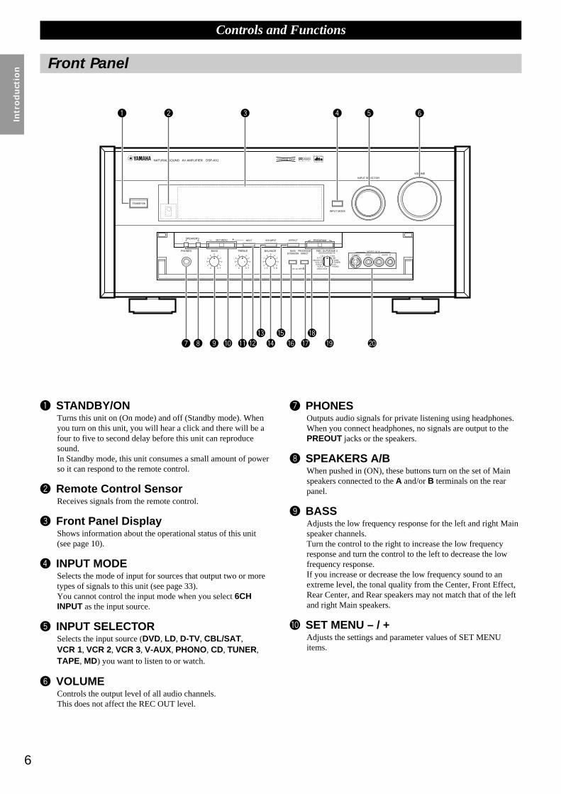
~ STANDBY/ONTurns this unit on (On mode) and off (Standby mode). Whenyou turn on this unit, you will hear a click and there will be afour to five to second delay before this unit can reproducesound.In Standby mode, this unit consumes a small amount of powerso it can respond to the remote control.
Ÿ Remote Control SensorReceives signals from the remote control.
! Front Panel DisplayShows information about the operational status of this unit(see page 10).
⁄ INPUT MODESelects the mode of input for sources that output two or moretypes of signals to this unit (see page 33).You cannot control the input mode when you select 6CHINPUT as the input source.
@ INPUT SELECTORSelects the input source (DVD, LD, D-TV, CBL/SAT ,VCR 1, VCR 2, VCR 3, V-AUX, PHONO, CD, TUNER,TAPE, MD) you want to listen to or watch.
¤ VOLUMEControls the output level of all audio channels.This does not affect the REC OUT level.
# PHONESOutputs audio signals for private listening using headphones.When you connect headphones, no signals are output to thePREOUT jacks or the speakers.
‹ SPEAKERS A/BWhen pushed in (ON), these buttons turn on the set of Mainspeakers connected to the A and/or B terminals on the rearpanel.
$ BASSAdjusts the low frequency response for the left and right Mainspeaker channels.Turn the control to the right to increase the low frequencyresponse and turn the control to the left to decrease the lowfrequency response.If you increase or decrease the low frequency sound to anextreme level, the tonal quality from the Center, Front Effect,Rear Center, and Rear speakers may not match that of the leftand right Main speakers.
› SET MENU – / +Adjusts the settings and parameter values of SET MENUitems.
PHONES BASS TREBLE
NATURAL SOUND AV AMPLIFIER DSP-AX1
INPUT MODE
INPUT SELECTOR
VOLUME
S VIDEO VIDEO L RAUDIO
VIDEO AUX
CINEMA DSP DOLBYD I G I T A L
D I G I T A L
S U R R O U N D
ON OFF5 54 4
3 3
2 21 1
0
+– 5 54 4
3 3
2 21 1
0
+– 5 54 4
3 3
2 21 1
0
RL
VCR 2 CDVCR 1 TUNER
CBL/SAT TAPED-TV MD
LD DVD
BALANCE
PHONOVCR 3VIDEO AUX
REC OUT/ZONE 2SOURCE/REMOTE
BASSEXTENSION
PROCESSORDIRECT
STANDBY/ON
6CH IMPUTSET MENU– + NEXT EFFECT PROGRAMSPEAKERSA B

7
English
‡ BASS EXTENSION ON/OFFWhen pushed in (ON), this feature boosts the bass frequencyof the left and right main channels by +6 dB (60 Hz) whilemaintaining overall tonal balance. This boost is useful if youdo not use a subwoofer.However, this boost may not be noticeable if the mainspeakers are set to “SMALL” and the bass output mode is setto “SW.”
* PROCESSOR DIRECT ON/OFFWhen pushed in (ON), BASS , TREBLE , BALANCE , andBASS EXTENSION are bypassed, eliminating any alterationof the original signal.
° PROGRAM /Selects the sound field program (see page 34).Selecting a sound field program turns on the effect.
( REC OUT/ZONE 2Selects the source you want to direct to the audio/videorecorder and ZONE 2 outputs independent of the source youare listening to in the main room. When set to the SOURCE/REMOTE position, the input source is directed to all outputs.
· VIDEO AUXInputs audio and video signals from a portable external sourcesuch as a video camera. To reproduce source signals fromthese jacks, select V-AUX as the input source. To direct thissource to the VCR 1 output jacks, select VIDEO AUX usingREC OUT/ZONE 2.
Controls and Functions
% TREBLEAdjusts the high frequency response for the left and right mainchannels.Turn the control to the right to increase the high frequencyresponse and turn the control to the left to decrease the highfrequency response.If you increase or decrease the high frequency sound to anextreme level, the tonal quality from the Center, Front Effect,Rear Center, and Rear speakers may not match that of the leftand right Main speakers.
fi NEXTDisplays SET MENU items. This button works like % on theremote control when using the SET MENU.
^ 6CH INPUTSwitches between 6CH INPUT mode and normal input modes.6CH INPUT mode takes priority over the source selected withINPUT SELECTOR.You cannot use DSP sound field programs while using anexternal decoder.
fl BALANCEControls the balance of the sound levels coming from the rightand left Main speaker(s). Setting this control to the centerposition “0” is appropriate for most situations.
& EFFECTSwitches the effect speakers (Center, Front Effect, Rear andRear Center) on and off. If you turn off the output of thesespeakers using EFFECT, all DTS and Dolby Digital audiosignals are directed to the Main left and right channels exceptfor the LFE channel.When DTS or Dolby Digital signals are mixed, the left andright Main channel signal levels may not match.
Opening and Closing the Front Panel DoorWhen you are not operating the controls behind the front panel door, close the door.
%%

8
Intr
od
uct
ion
ON SCREEN LEVEL
SLEEP TEST
PARAMETER
SET MENU%%
TRANSMIT RE-NAME CLEARMACRO
MACROLEARN OFF ON
SYSTEMPOWER STANDBY V-AUX TAPE PHONO
D-TV CBL/SAT TUNER MD CD
VCR 1 VCR 2 VCR 3 LD DVD
6CH INPUT
TITLE
ENTER
MENU SOUNDDISPLAY
SOURCE
SELECT SEARCH CHAPTER
%
! !$
* #
$
%%
%%%
10KEY DSP HALL 1 HALL 2 CHURCH JAZZ CLUB
ROCKCONCERT
ENTER-TAINMENT
CONCERTVIDEO 2
CONCERTVIDEO 1
POWER REC STOP PAUSE PLAY
6.1/ESTV
THEATERMOVIE
THEATER 2MOVIE
THEATER 1 /DTS
SUR.
0 +10 +100
1 2 3 4
5 6 7 8
9 10 11 12
+ + +TV VOL
A / B / C / D / E PRESET
TV INPUT
TV MUTE
CH
DISC
MUTE
EFFECT
VOLUME
+–
/
CHP/INDEX
– – –
Controls and Functions
Remote Control
Power ButtonsTurn the power on and off.Press SYSTEM POWER to turn on thepower and STANDBY to turn off(Standby mode) the power to the mainunit.
Display WindowShows the source componentthat you select to control.
Program/10-Key SectionFunctions as the numeric buttons or DSPprogram group buttons.
Source SelectSelects the source componentwithout switching the input.
Setup SectionSets speaker output levels, SETMENU, DSP parameters, etc.
OthersFunctions vary depending on yourcomponents that are set up with themanufacturer code.
Programming SectionProvides a selection of programmingtypes you can utilize to convenientlyoperate your other components.
Input SectionSelects the input source.Press an input button repeatedly to selectthe input mode.
Operation SectionProvides functions such as play, stop, skip, etc.for operating your other components.
Volume SectionControls the volume.

9
English
Controls and Functions
~ Infrared windowOutputs infrared control signals. Aim this window at thecomponent you want to operate.
Ÿ CLEARUsed for clearing functions acquired using the Learn andRename features, programmed macros, and presetmanufacturer codes (see pages 61, 62).
! RE-NAMEUsed for changing the source name in the display window (seepage 61).
⁄ LEARNUsed for setting up the manufacturer code or programming thefunctions of other remote controls (see pages 57, 58).
@ MACROUsed to program a series of operations onto a single button(see page 59).
¤ MACRO ON/OFFTurns the macro function on and off.
# TRANSMITFlashes while the remote control is sending signals.
‹ 6CH INPUTSwitches to the 6CH INPUT mode when using an externaldecoder.
$ LIGHTTurns the light on or off.When you press this button once, the light turns on for aboutten seconds. Press again to turn off the light.
› 10KEY/DSPSelects the numeric button (10KEY) mode or DSP mode. Youcan use the 13 buttons to select numbers or DSP programsdirectly according to the position of this switch.
% DSP program group/Numeric buttonsSelect DSP programs or numbers according to the position of10KEY/DSP. (Press a button repeatedly to select a DSPprogram within that group.)
fi A/B/C/D/ESelects one of the five preset station groups.
TV operation buttonsTV INPUT switches between TV and VCR mode.TV MUTE mutes the TV sound.
^ TV VOL +/–Increases or decreases the TV volume level.
fl +/–PRESET +/– selects a preset station.CH +/– selects the next or previous channel.DISC +/– skips to the next or previous disc.
& MUTEMutes the sound. Press again to restore audio output at theprevious volume level.
‡ VOLUME +/–Increases or decreases the volume level.
* EFFECTSwitches the effect speakers (center, front, rear, and rearcenter) on and off. If the output of these speakers is switchedoff, all DTS and Dolby Digital audio signals are directed to themain left and right channels except for the LFE channel.
° CoverSlides down to show the setup buttons.
( LEVELSelects the effect speaker channels (center, front, rear andsubwoofer) so you can adjust their level independently. Pressthis button repeatedly to select the effect speaker channel youwant to adjust, then use + or – to adjust the level.
· ON SCREENSelects the On-Screen Display mode for your video monitor.
) SLEEP TimerSets the Sleep Timer. Press repeatedly to set the amount oftime before the main unit is automatically turned off.
‚ TESTSelects the test mode (see page 27).
_ PARAMETER/SET MENUSelects the PARAMETER mode or SET MENU mode.
You can use the cursor % /
%
/ + / – buttons to adjust DSPprogram parameter values or SET MENU items according tothe position of this switch.
— Cursor buttons % / % / + / –Selects and adjusts DSP program parameters and SET MENUitems according to the position of PARAMETER/SETMENU.
+ RESETPress this button after you exchange batteries or when theremote control stops working properly. (Pressing RESET doesnot clear acquired functions.)
10
Intr
od
uct
ion
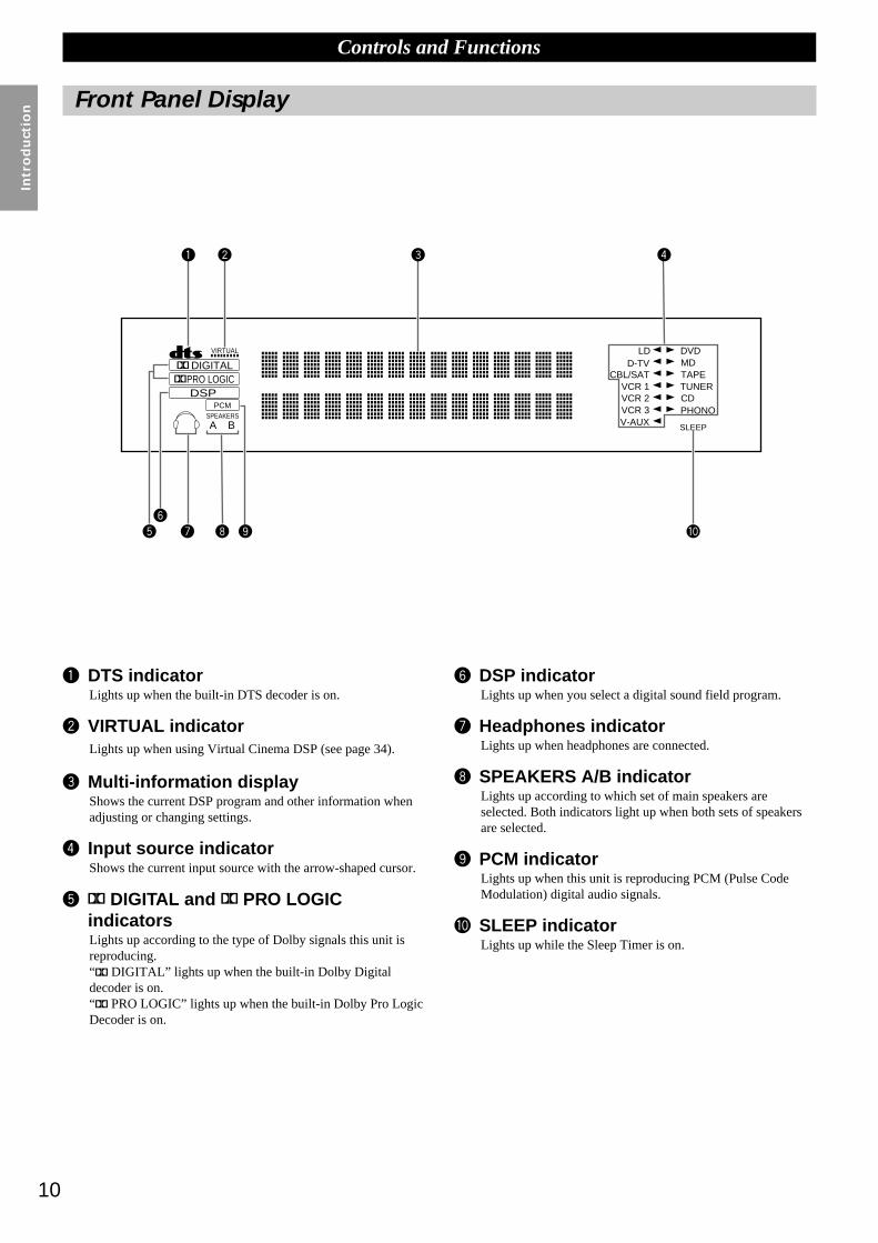
~ DTS indicatorLights up when the built-in DTS decoder is on.
Ÿ VIRTUAL indicatorLights up when using Virtual Cinema DSP (see page 34).
! Multi-information displayShows the current DSP program and other information whenadjusting or changing settings.
⁄ Input source indicatorShows the current input source with the arrow-shaped cursor.
@ DIGITAL and PRO LOGICindicatorsLights up according to the type of Dolby signals this unit isreproducing.“ DIGITAL” lights up when the built-in Dolby Digitaldecoder is on.“ PRO LOGIC” lights up when the built-in Dolby Pro LogicDecoder is on.
Controls and Functions
Front Panel Display
DIGITAL
DSPPCM
PRO LOGIC
SPEAKERS
A B
LDD-TV
CBL/SATVCR 1VCR 2VCR 3V-AUX
DVDMDTAPETUNERCDPHONO
VIRTUAL
SLEEP
STEREO
AUTOTUNING
MEMORY
¤ DSP indicatorLights up when you select a digital sound field program.
# Headphones indicatorLights up when headphones are connected.
‹ SPEAKERS A/B indicatorLights up according to which set of main speakers areselected. Both indicators light up when both sets of speakersare selected.
$ PCM indicatorLights up when this unit is reproducing PCM (Pulse CodeModulation) digital audio signals.
› SLEEP indicatorLights up while the Sleep Timer is on.
11
English
Controls and Functions
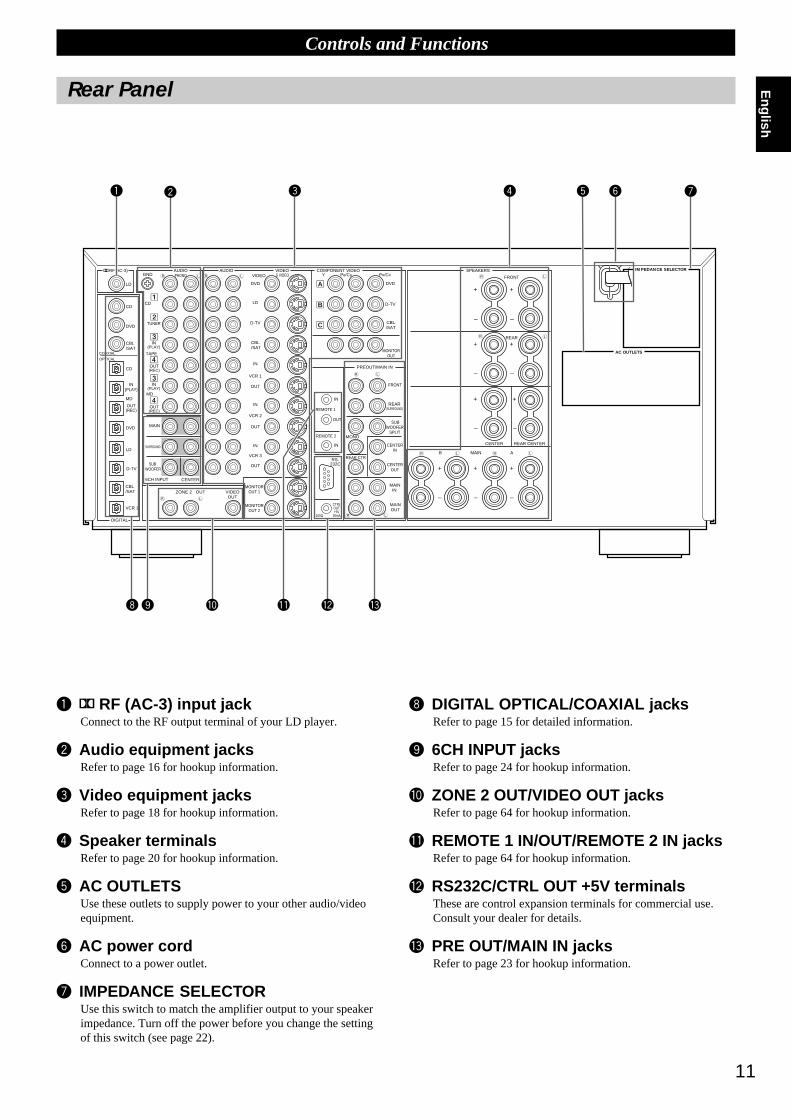
~ RF (AC-3) input jackConnect to the RF output terminal of your LD player.
Ÿ Audio equipment jacksRefer to page 16 for hookup information.
! Video equipment jacksRefer to page 18 for hookup information.
⁄ Speaker terminalsRefer to page 20 for hookup information.
@ AC OUTLETSUse these outlets to supply power to your other audio/videoequipment.
¤ AC power cordConnect to a power outlet.
# IMPEDANCE SELECTORUse this switch to match the amplifier output to your speakerimpedance. Turn off the power before you change the settingof this switch (see page 22).
Rear Panel
AC OUTLETS
IMPEDANCE SELECTOR
VOLTAGE SELECTOR
MAIN
CENTER
SUB WOOFER
6CH INPUT
SURROUND
TUNER
IN(PLAY)
IN(PLAY)
CD
GND
TAPE
OUT(REC)
OUT(REC)
MD
VCR 1
VCR 2
VCR 3
DVD
VIDEO
LD
D-TV
CBL/SAT
IN
DVD
D-TV
CBL/SAT
MONITOROUT
IN
IN
IN
IN
OUT
OUT
OUT
CD
CD
DVD
DVD
LD
LD
VCR 1
D-TV
MD
OUT(REC)
IN(PLAY)
CBL/SAT
CBL/SAT
AUDIOPHONO
AUDIO VIDEOS VIDEO
COMPONENT VIDEO
PREOUT/MAIN IN
SPEAKERS
FRONT
REAR
CENTER REAR CENTER
AMAINB
PR/CRPB/CBY
FRONT
REAR(SURROUND)
SUBWOOFER
SPLIT
CENTERIN
CENTEROUT
MAININ
MAINOUT
MONO
REAR CTRRS-232C
OUT
REMOTE 1
REMOTE 2
CTRLOUT+5V
20mA100Ω
+
–
+
–
+
–
+
–
+
–
+
–
+
–
+
–
+
–
ZONE 2 OUT VIDEOOUT
COAXIAL
OPTICAL
DIGITAL
RF(AC-3)
MONITOROUT 1
MONITOROUT 2
A
B
C
‹ DIGITAL OPTICAL/COAXIAL jacksRefer to page 15 for detailed information.
$ 6CH INPUT jacksRefer to page 24 for hookup information.
› ZONE 2 OUT/VIDEO OUT jacksRefer to page 64 for hookup information.
% REMOTE 1 IN/OUT/REMOTE 2 IN jacksRefer to page 64 for hookup information.
fi RS232C/CTRL OUT +5V terminalsThese are control expansion terminals for commercial use.Consult your dealer for details.
^ PRE OUT/MAIN IN jacksRefer to page 23 for hookup information.

12
Pre
para
tio
ns
Preparations
Speaker System Configurations 13
Eight or Seven Speaker Configuration –Full Cinema DSP– ............................ 13Six Speaker Configuration –Hi Fi DSP– .......................................................... 13Five Speaker Configuration –Standard 5.1 Channel– ....................................... 13Four Speaker Configuration –Minimum Requirement– ................................... 13
Speaker Placement 14
Placing the Main Speakers ................................................................................ 14Placing the Center Speaker ............................................................................... 14Placing the Front Effect, Rear and Rear Center Speakers ................................ 14When You Use a Projection Screen .................................................................. 14Placing the Subwoofers ..................................................................................... 14
Hookups 15
Connecting to Digital Jacks .............................................................................. 15About the Video Jacks ...................................................................................... 15About the RF (AC-3) Signal Input Jack ....................................................... 15Connecting Audio Components ........................................................................ 16Connecting Video Components ........................................................................ 18Connecting Speakers ......................................................................................... 20Connecting External Amplifiers ....................................................................... 23Connecting an External Decoder ...................................................................... 24Connecting Power Supply Cords ...................................................................... 24
On-Screen Displays (OSD) 25
OSD Modes ....................................................................................................... 25Selecting the OSD Mode .................................................................................. 25
Speaker Settings 26
Speaker Output Levels 27
Before You Begin ............................................................................................. 27Dolby Surround Test ......................................................................................... 28DSP Test ........................................................................................................... 29

13
English
( )
Speaker System Configurations
The most complete speaker configuration consists of eight speakers: the left and right Main speakers, a Center speaker, the left and right Rearspeakers, the left and right Front Effect speakers, and a Rear Center speaker. If you do not use eight speakers, you can direct the signals forspeakers that are not in your system to other speakers in your configuration. A Subwoofer can be used with any of these configurations toproduce a fuller sound.
Eight or Seven Speaker Configuration –Full Cinema DSP–When you reproduce feature film software, this configuration fullly expresses thepowerful and realistic sound qualities of 70 mm multitrack audio. The dialogue ispositioned as if it were coming from directly on the screen, the sound effect ispositioned slightlly behind the screen, and the soundtrack music is positionedeven further behind the screen to express the width and depth of the overallpresentation. This configuration makes the most of this unit's capability.
The Rear Center speaker is useful for playback of Dolby Digital Surround EX orDTS ES.
Six Speaker Configuration –Hi Fi DSP–This configuration is used the most for audio playback with HiFi DSP. It does notposition the dialogue sound as well as a seven or eight speaker configuration.However, it creates a dynamic DSP (Digital Sound Field Processor) sound fieldwhich adds depth to the sound.
For this speaker configuration, change SET MENU item 1A. CENTER SP to“NONE” and 1D. REAR CT SP to “NONE” (see page 37).
Five Speaker Configuration –Standard 5.1 Channel–This configuration does not express the height of the sound field as well as theseven or eight speaker configuration. However, it positions the dialogue sound ascoming directly from the screen.
For this speaker configuration, change SET MENU item 1F. FRNT EFCT SP to“NONE” and 1D. REAR CT SP to “NONE” (see page 37).
Four Speaker Configuration –Minimum Requirement–In this configuration, the Center speaker signals and Front Effect speaker signalsare directed to the left and right Main speakers.
For this speaker configuration, change SET MENU item 1A. CENTER SP to“NONE,” item 1F. FRNT EFCT SP to “NONE,” and item 1D. REAR CT SP to“NONE” (see page 37).
Front Effect Speakers
Front Subwoofer
Center Speaker
Main Speakers
Rear Speakers
Rear Center Speaker
Rear Subwoofer

14
Pre
para
tio
ns
FLL
RL
C RFR
RRRC
Speaker Placement
Where you place your speakers has a tremendous effect on how well your system sounds.
Placing the Main SpeakersPlace the left and right Main speakers an equal distance from the main listeningposition.
If you have a TV or video monitor in your system, the distance of each speakerfrom each side of the TV or video monitor should be the same.
Placing the Center SpeakerIf you have a TV or video monitor in your system, align the front face of theCenter speaker with the front face of the monitor. Place the speaker as close to themonitor as possible, such as directly over or under the monitor. If you place thespeaker under the monitor, the Front Effect speakers can adjust the height of thesound to correspond with the action on the screen (depending on the listener’sposition). If you have a projection screen in your system, place the Center speakerunder the screen. Be sure to align the speaker with the center of the screen.
Placing the Front Effect, Rear and Rear CenterSpeakersThese speakers should be placed about 0.5~1m (1~3 feet) outside the Mainspeakers and in the front of the room. They should be turned toward the mainlistening position. Place the Rear speakers in the back of the room so they face themain listening position. The Rear speakers can be placed farther apart than theFront Effect speakers. The Front Effect and Rear speakers should be placed about1.8m (6 feet) above the floor.
Once you begin listening to programs, continue to adjust the speaker placementuntil you obtain a balanced sound from the Main speakers and the Front Effectand Rear speakers.
When You Use a Projection ScreenPlace the speakers as shown in the illustration.
The Main speakers should be placed about one-quarter of the way up from thebottom of the screen.
Place the Center speaker in the center and directly under the screen. The Centerspeaker provides precise dialogue localization.
When you use a projection screen with your system, the Front Effect speakersprovide better effect quality. The CINEMA-DSP sound field programs (see page34) raise the sound from the Center speaker upward and provide natural soundcorresponding with the video images.
Placing the SubwoofersPlace the Front Subwoofer near the Main speakers. Turn it slightly toward the center of the room to reduce wall reflections.
If you use a Rear Subwoofer, place it behind the main listening position. The placement of the Rear Subwoofer is not critical because ofthe ultralow frequencies of the sound being reproduced.
By adding a high quality Subwoofer to the speaker configurations shown on pages 21 and 22, you can enjoy more powerful and realisticmovie effects, even if your Main speakers are large.
Note:
• If you use different brands of speakers (with different tonal qualities) in yourconfiguration, the tone of a moving human voice and other types of sound may notshift smoothly. We recommend that you use speakers from the same manufacturer orspeakers with the same tonal quality.You can also adjust the output levels and equalization of your effect speakers using theSET MENU (see page 37).If you are using small speakers, the addition of a Subwoofer will reinforce the soundeffects of movies (see page 21).
L
C
R1/4
1
Mainspeaker
Mainspeaker
TV or Videomonitor
TV or Videomonitor
Center speaker
Front Effectspeakers
Front Subwoofer
Rear Subwoofer
Rear Centerspeaker
Rear speakers
Center speaker
1m 1m0.5~1m 1.5~3m 0.5~1m(3ft) (3ft)(1~3ft) (5~15ft) (1~3ft)
Main speakers
15
English
Connecting to Digital JacksThe DSP-AX1 has digital jacks for direct transmission of digital signals through either coaxial or fiber optic cables. You can use the digitaljacks to input PCM, DTS and Dolby Digital bitstreams. When you connect components to both the COAXIAL and OPTICAL jacks (for CD,DVD, and CBL/SAT) priority is given to the input signals from the COAXIAL jack. All digital input jacks are acceptable for 96 kHz/24 bitdigital signals.
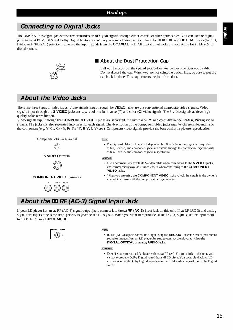
About the Dust Protection CapPull out the cap from the optical jack before you connect the fiber optic cable.Do not discard the cap. When you are not using the optical jack, be sure to put thecap back in place. This cap protects the jack from dust.
About the Video JacksThere are three types of video jacks. Video signals input through the VIDEO jacks are the conventional composite video signals. Videosignals input through the S VIDEO jacks are separated into luminance (Y) and color (C) video signals. The S-video signals achieve highquality color reproduction.Video signals input through the COMPONENT VIDEO jacks are separated into luminance (Y) and color difference (PB/CB, PR/CR) videosignals. The jacks are also separated into three for each signal. The description of the component video jacks may be different depending onthe component (e.g. Y, CB, CR / Y, PB, PR / Y, B-Y, R-Y/ etc.). Component video signals provide the best quality in picture reproduction.
Note:
• Each type of video jack works independently. Signals input through the compositevideo, S-video, and component jacks are output through the corresponding compositevideo, S-video, and component jacks respectively.
Caution:
• Use a commercially available S-video cable when connecting to the S VIDEO jacks,and commercially available video cables when connecting to the COMPONENTVIDEO jacks.
• When you are using the COMPONENT VIDEO jacks, check the details in the owner’smanual that came with the component being connected.
About the RF (AC-3) Signal Input JackIf your LD player has an RF (AC-3) signal output jack, connect it to the RF (AC-3) input jack on this unit. If RF (AC-3) and analogsignals are input at the same time, priority is given to the RF signals. When you want to reproduce RF (AC-3) signals, set the input modeto “D.D. RF” using INPUT MODE.
Note:
• RF (AC-3) signals cannot be output using the REC OUT selector. When you recordsound or images from an LD player, be sure to connect the player to either theDIGITAL OPTICAL or analog AUDIO jacks.
Caution:
• Even if you connect an LD player with an RF (AC-3) output jack to this unit, youcannot reproduce Dolby Digital sound from all LD discs. You must playback an LDdisc encoded with Dolby Digital signals in order to take advantage of the Dolby Digitalsound.
Hookups
RF(AC-3)
LD
PR/CRPB/CBY
Composite VIDEO terminal
S VIDEO terminal
COMPONENT VIDEO terminals
16
Pre
para
tio
ns
Hookups
Connecting Audio ComponentsBefore you connect any components, disconnect the power supply to all the components you plan to connect including the DSP-AX1 anddetermine which jacks are for the left and right channels and for input and output.When you connect other YAMAHA audio equipment (such as a CD player or changer, Tuner, MD deck, or tape deck), connect to terminalswith the same number labels. Yamaha applies this labelling system to all its products.In the hookup illustrations on the following pages:
After you finish all hookups, check them again to make sure they are correct.
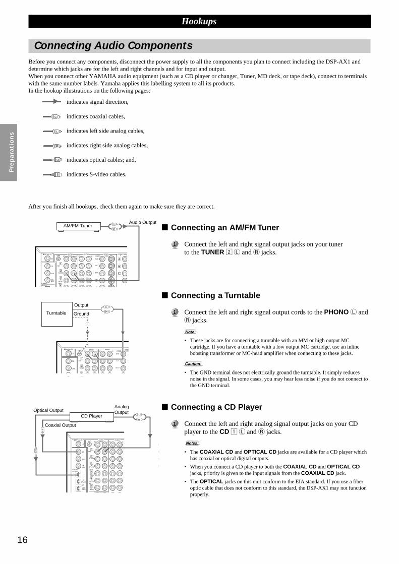
Connecting an AM/FM Tuner
11 Connect the left and right signal output jacks on your tunerto the TUNER 2 L and R jacks.
Connecting a Turntable
11 Connect the left and right signal output cords to the PHONO L andR jacks.
Note:
• These jacks are for connecting a turntable with an MM or high output MCcartridge. If you have a turntable with a low output MC cartridge, use an inlineboosting transformer or MC-head amplifier when connecting to these jacks.
Caution:
• The GND terminal does not electrically ground the turntable. It simply reducesnoise in the signal. In some cases, you may hear less noise if you do not connect tothe GND terminal.
Connecting a CD Player
11 Connect the left and right analog signal output jacks on your CDplayer to the CD 1 L and R jacks.
Notes:
• The COAXIAL CD and OPTICAL CD jacks are available for a CD player whichhas coaxial or optical digital outputs.
• When you connect a CD player to both the COAXIAL CD and OPTICAL CDjacks, priority is given to the input signals from the COAXIAL CD jack.
• The OPTICAL jacks on this unit conform to the EIA standard. If you use a fiberoptic cable that does not conform to this standard, the DSP-AX1 may not functionproperly.
TUNER
IN(PLAY)
CD
GND
DVD
VIDEO
LD
D-TV
CBL/SAT
CD
DVD
LD
CBL/SAT
AUDIOPHONO
AUDIO VIDEOS VIDEO
RF(AC-3)
L
R
TUNER
IN(PLAY)
CD
GND
TAPE
OUT(REC)
DVD
VIDEO
LD
D-TV
CBL/SAT
IN
M
CD
CD
DVD
LD
CBL/SAT
AUDIOPHONO
AUDIO VIDEOS VIDEO
COMPONENT VIDEO
PREOUT/MAIN
PR/PB/CBY
COAXIAL
OPTICAL
RF(AC-3)
A
B
C
L
R
MAIN
TUNER
IN(PLAY)
IN(PLAY)
CD
GND
TAPE
OUT(REC)
OUT(REC)
MD
VCR 1
VCR 2
DVD
VIDEO
LD
D-TV
CBL/SAT
IN
ININ
OUT
OUT
CD
CD
DVD
DVD
LD
MD
OUT(REC)
IN(PLAY)
CBL/SAT
AUDIOPHONO
AUDIO VIDEOS VIDEO
COMPONENPY
OUT
REMOTE 1
COAXIAL
OPTICAL
RF(AC-3)
A
B
C
O
C
L
R
AM/FM TunerAudio Output
Turntable
Output
Ground
CD PlayerOptical Output
Coaxial Output
AnalogOutput
indicates signal direction,
indicates coaxial cables,
indicates left side analog cables,
indicates right side analog cables,
indicates optical cables; and,
indicates S-video cables.
C
O
S
L
R
17
English
Connecting a Tape Deck
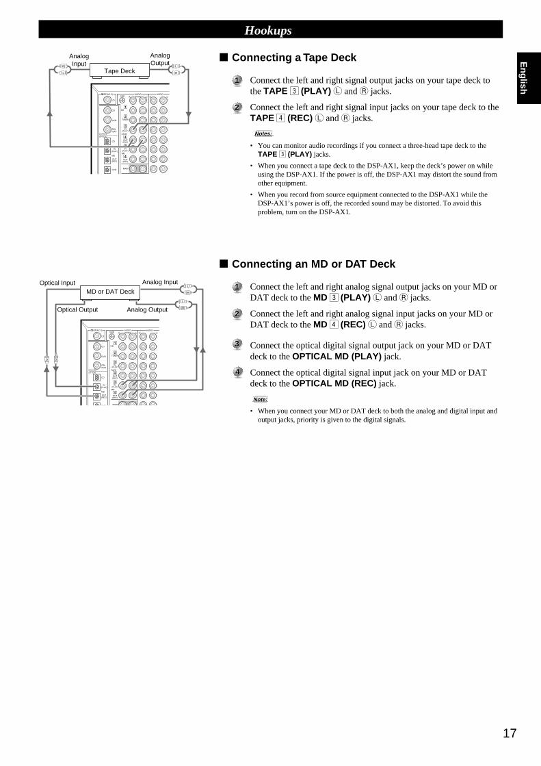
11 Connect the left and right signal output jacks on your tape deck tothe TAPE 3 (PLAY) L and R jacks.
22 Connect the left and right signal input jacks on your tape deck to theTAPE 4 (REC) L and R jacks.
Notes:
• You can monitor audio recordings if you connect a three-head tape deck to theTAPE 3 (PLAY) jacks.
• When you connect a tape deck to the DSP-AX1, keep the deck’s power on whileusing the DSP-AX1. If the power is off, the DSP-AX1 may distort the sound fromother equipment.
• When you record from source equipment connected to the DSP-AX1 while theDSP-AX1’s power is off, the recorded sound may be distorted. To avoid thisproblem, turn on the DSP-AX1.
Connecting an MD or DAT Deck
11 Connect the left and right analog signal output jacks on your MD orDAT deck to the MD 3 (PLAY) L and R jacks.
22 Connect the left and right analog signal input jacks on your MD orDAT deck to the MD 4 (REC) L and R jacks.
33 Connect the optical digital signal output jack on your MD or DATdeck to the OPTICAL MD (PLAY) jack.
44 Connect the optical digital signal input jack on your MD or DATdeck to the OPTICAL MD (REC) jack.
Note:
• When you connect your MD or DAT deck to both the analog and digital input andoutput jacks, priority is given to the digital signals.
MAIN
TUNER
IN(PLAY)
IN(PLAY)
CD
GND
TAPE
OUT(REC)
OUT(REC)
MD
VCR 1
VCR 2
DVD
VIDEO
LD
D-TV
CBL/SAT
IN
IN
IN
IN
OUT
OUT
CD
CD
DVD
DVD
LD
MD
OUT(REC)
IN(PLAY)
CBL/SAT
AUDIOPHONO
AUDIO VIDEOS VIDEO
COMPONENT VIPB/CBY
MO
OUT
REMOTE 1
REMOTE 2
COAXIAL
OPTICAL
RF(AC-3)
A
B
CO
L
R
O
L
R
Hookups
MAIN
SURROUND
TUNER
IN(PLAY)
IN(PLAY)
CD
GND
TAPE
OUT(REC)
OUT(REC)
MD
VCR 1
VCR 2
DVD
VIDEO
LD
D-TV
CBL/SAT
IN
IN
IN
OUT
OUT
CD
CD
DVD
DVD
LD
LD
MD
OUT(REC)
IN(PLAY)
CBL/SAT
AUDIOPHONO
AUDIO VIDEOS VIDEO
COAXIAL
OPTICAL
RF(AC-3)
L
RL
R
Tape Deck
AnalogInput
AnalogOutput
MD or DAT Deck
Analog Input
Analog Output
Optical Input
Optical Output
18
Pre
para
tio
ns
Connecting Video ComponentsBefore you connect any components, disconnect the power supply to all the components you plan to connect including the DSP-AX1 anddetermine which jacks are for the left and right channels and for input and output. After you finish all hookups, check them again to makesure they are correct.
Note:
• If you make S-video connections to this unit, it is not necessary to make composite video connections. If both types of connections are made, this unit givespriority to the S-video signal.
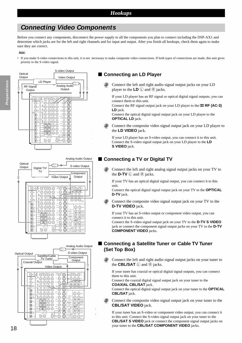
Connecting an LD Player
11 Connect the left and right audio signal output jacks on your LDplayer to the LD L and R jacks.
If your LD player has an RF signal or optical digital signal outputs, you canconnect them to this unit.Connect the RF signal output jack on your LD player to the RF (AC-3)LD jack.Connect the optical digital signal output jack on your LD player to theOPTICAL LD jack.
22 Connect the composite video signal output jack on your LD player tothe LD VIDEO jack.
If your LD player has an S-video output, you can connect it to this unit.Connect the S-video signal output jack on your LD player to the LDS VIDEO jack.
Connecting a TV or Digital TV
11 Connect the left and right analog signal output jacks on your TV tothe D-TV L and R jacks.
If your TV has an optical digital signal output, you can connect it to thisunit.Connect the optical digital signal output jack on your TV to the OPTICALD-TV jack.
22 Connect the composite video signal output jack on your TV to theD-TV VIDEO jack.
If your TV has an S-video output or component video output, you canconnect it to this unit.Connect the S-video signal output jack on your TV to the D-TV S VIDEOjack or connect the component signal output jacks on your TV to the D-TVCOMPONENT VIDEO jacks.
Connecting a Satellite Tuner or Cable TV Tuner(Set Top Box)
11 Connect the left and right audio signal output jacks on your tuner tothe CBL/SAT L and R jacks.
If your tuner has coaxial or optical digital signal outputs, you can connectthem to this unit.Connect the coaxial digital signal output jack on your tuner to theCOAXIAL CBL/SAT jack.Connect the optical digital signal output jack on your tuner to the OPTICALCBL/SAT jack.
22 Connect the composite video signal output jack on your tuner to theCBL/SAT VIDEO jack.
If your tuner has an S-video or component video output, you can connect itto this unit. Connect the S-video signal output jack on your tuner to theCBL/SAT S VIDEO jack or connect the component signal output jacks onyour tuner to the CBL/SAT COMPONENT VIDEO jacks.
MAIN
CENTER
SUB WOOFER
6CH INPUT
SURROUND
TUNER
IN(PLAY)
IN(PLAY)
CD
GND
TAPE
OUT(REC)
OUT(REC)
MD
VCR 1
VCR 2
VCR 3
DVD
VIDEO
LD
D-TV
CBL/SAT
IN
DVD
D-TV
CBL/SAT
MONITOROUT
IN
IN
IN
IN
OUT
OUT
OUT
CD
CD
DVD
DVD
LD
LD
VCR 1
D-TV
MD
OUT(REC)
IN(PLAY)
CBL/SAT
CBL/SAT
AUDIOPHONO
AUDIO VIDEOS VIDEO
COMPONENT VIDEO
PREOUT/MAIN IN
B
PR/CRPB/CBY
FRONT
REAR(SURROUND)
SUBWOOFER
SPLIT
CENTERIN
CENTEROUT
MAININ
MAINOUT
MONO
REAR CTRRB-2320
RS232C
OUT
REMOTE 1
REMOTE 2
CTRLOUT+5V
20mA100Ω
+
–ZONE 2 OUT VIDEO
OUT
COAXIAL
OPTICAL
DIGITAL
RF(AC-3)
MONITOROUT 1
MONITOROUT 2
A
B
C
C
SO
L
R
Hookups
MAIN
CENTER
SUB WOOFER
6CH INPUT
SURROUND
TUNER
IN(PLAY)
IN(PLAY)
CD
GND
TAPE
OUT(REC)
OUT(REC)
MD
VCR 1
VCR 2
VCR 3
DVD
VIDEO
LD
D-TV
CBL/SAT
IN
DVD
D-TV
CBL/SAT
MONITOROUT
IN
IN
IN
IN
OUT
OUT
OUT
CD
CD
DVD
DVD
LD
LD
VCR 1
D-TV
MD
OUT(REC)
IN(PLAY)
CBL/SAT
CBL/SAT
AUDIOPHONO
AUDIO VIDEOS VIDEO
COMPONENT VIDEO
PREOUT/MAIN IN
PR/CRPB/CBY
FRONT
REAR(SURROUND)
SUBWOOFER
SPLIT
CENTERIN
CENTEROUT
MAININ
MAINOUT
MONO
REAR CTRRB-2320
RS232C
OUT
REMOTE 1
REMOTE 2
CTRLOUT+5V
20mA
ZONE 2 OUT VIDEOOUT
COAXIAL
OPTICAL
DIGITAL
RF(AC-3)
MONITOROUT 1
MONITOROUT 2
100Ω
A
B
C
CC SO
L
R
MAIN
CENTER
SUB WOOFER
6CH INPUT
SURROUND
TUNER
IN(PLAY)
IN(PLAY)
CD
GND
TAPE
OUT(REC)
OUT(REC)
MD
VCR 1
VCR 2
VCR 3
DVD
VIDEO
LD
D-TV
CBL/SAT
IN
DVD
D-TV
CBL/SAT
MONITOROUT
IN
IN
IN
IN
OUT
OUT
OUT
CD
CD
DVD
DVD
LD
LD
VCR 1
D-TV
MD
OUT(REC)
IN(PLAY)
CBL/SAT
CBL/SAT
AUDIOPHONO
AUDIO VIDEOS VIDEO
COMPONENT VIDEO
PREOUT/MAIN IN
S
B
PR/CRPB/CBY
FRONT
REAR(SURROUND)
SUBWOOFER
SPLIT
CENTERIN
CENTEROUT
MAININ
MAINOUT
MONO
REAR CTRRB-2320
RS232C
OUT
REMOTE 1
REMOTE 2
CTRLOUT+5V
20mA100Ω
+
–ZONE 2 OUT VIDEO
OUT
COAXIAL
OPTICAL
DIGITAL
RF(AC-3)
MONITOROUT 1
MONITOROUT 2
A
B
C
CSO
L
R
C
LD Player
OpticalOutput
RF-SignalOutput
Analog AudioOutput
OpticalOutput Digital TV/
TV
Analog Audio Output
S-video Output
Video Output
Optical Output
Coaxial Output
Analog Audio Output
S-video Output
ComponentOutput
Satellite/CableTV Tuner
Video Output
ComponentOutput
S-video Output
Video Output

19
English
Hookups
Connecting a VCR
11 Connect the left and right audio signal output jacks on your VCR tothe VCR 1 IN L and R jacks.
22 Connect the left and right audio signal input jacks on your VCR tothe VCR 1 OUT L and R jacks.
33 Connect the composite video signal output jack on your VCR to theVCR 1 VIDEO IN jack.
If your VCR has an S-video output, you can connect it to this unit.Connect the S-video signal output jack on your VCR to the VCR 1 IN SVIDEO jack.
44 Connect the composite video signal input jack on your VCR to theVCR 1 VIDEO OUT jack.
If your VCR has an S-video input, you can connect it to this unit.Connect the S-video signal input jack on your VCR to the VCR 1 OUT SVIDEO jack.
Notes:
• You can connect other VCRs to the DSP-AX1 using the VCR 2 and VCR 3 jacks.
• If your VCR has an optical digital signal output jack, connect it to the OPTICALVCR 1 jack of this unit.
Connecting a DVD Player
11 Connect the left and right analog signal output jacks on your DVDplayer to the DVD L and R jacks.
If your DVD player has coaxial or optical digital outputs, you can connectone or both of them to this unit.Connect the coaxial digital signal output jack on your DVD player to theCOAXIAL DVD jack.Connect the optical digital signal output jack on your DVD player to theOPTICAL DVD jack.
22 Connect the composite video signal output jack on your DVD playerto the DVD VIDEO jack.
If your DVD player has an S-video output or component video output, youcan connect it to this unit. Connect the S-video signal output jack on yourDVD player to the DVD S-VIDEO jack or connect the component signaloutput jacks on your DVD player to the DVD COMPONENT VIDEOjacks.
Connecting a Video Monitor
11 Connect the composite video signal input jack on your monitor toMONITOR OUT 1 VIDEO jack.
If your video monitor has an S-video input, you can connect it to this unit.Connect the S-video signal input jack on your video monitor to theMONITOR OUT 1 S-VIDEO jack.If your video monitor has component video signal inputs, you can connectthem to the COMPONENT VIDEO MONITOR OUT jacks.
Note:
• You can connect another monitor to this unit using the MONITOR OUT 2 jacks.
MAIN
CENTER
SUB WOOFER
6CH INPUT
SURROUND
TUNER
IN(PLAY)
IN(PLAY)
CD
TAPE
OUT(REC)
OUT(REC)
MD
VCR 1
VCR 2
VCR 3
D-TV
CBL/SAT
IN
D-TV
CBL/SAT
MONITOROUT
IN
IN
IN
IN
OUT
OUT
OUT
CD
CD
DVD
DVD
LD
VCR 1
D-TV
MD
OUT(REC)
IN(PLAY)
CBL/SAT
CBL/SAT
PREOUT/MAIN IN
FRONT
REAR(SURROUND)
SUBWOOFER
SPLIT
CENTERIN
CENTEROUT
MAININ
MAINOUT
MONO
REAR CTRRB-2320
RS232C
OUT
REMOTE 1
REMOTE 2
CTRLOUT+5V
20mA100Ω
ZONE 2 OUT VIDEOOUT
COAXIAL
OPTICAL
DIGITAL
MONITOROUT 1
MONITOROUT 2
B
C
SC
MAIN
TUNER
IN(PLAY)
IN(PLAY)
CD
GND
TAPE
OUT(REC)
OUT(REC)
MD
VCR 1
VCR 2
DVD
VIDEO
LD
D-TV
CBL/SAT
IN
DVD
D-TV
CBL/SAT
MONITOROUT
ININ
OUT
OUT
CD
CD
DVD
DVD
LD
MD
OUT(REC)
IN(PLAY)
CBL/SAT
AUDIOPHONO
AUDIO VIDEOS VIDEO
COMPONENT VIDEO
PREOUT/MAIN IN
SPR/CRPB/CBY
FRONT
REAR(SURROUND)
SUBWOOFER
SPLIT MONO
OUT
REMOTE 1
REMOTE 2
COAXIAL
OPTICAL
RF(AC-3)
A
B
C
C CO S
L R
MAIN
CENTER
SUB WOOFER
6CH INPUT
SURROUND
TUNER
IN(PLAY)
IN(PLAY)
CD
GND
TAPE
OUT(REC)
OUT(REC)
MD
VCR 1
VCR 2
VCR 3
DVD
VIDEO
LD
D-TV
CBL/SAT
IN
DVD
D-TV
CBL/SAT
MONITOROUT
IN
IN
IN
IN
OUT
OUT
OUT
CD
CD
DVD
DVD
LD
LD
VCR 1
D-TV
MD
OUT(REC)
IN(PLAY)
CBL/SAT
CBL/SAT
AUDIOPHONO
AUDIO VIDEOS VIDEO
COMPONENT VIDEO
PREOUT/MAIN IN
PR/CRPB/CBY
FRONT
REAR(SURROUND)
SUBWOOFER
SPLIT
CENTERIN
CENTEROUT
MAININ
MAINOUT
MONO
REAR CTRRB-2320
RS232C
OUT
REMOTE 1
REMOTE 2
CTRLOUT+5V
20mA100Ω
ZONE 2 OUT VIDEOOUT
COAXIAL
OPTICAL
DIGITAL
RF(AC-3)
MONITOROUT 1
MONITOROUT 2
A
B
C
C
L
R
L
R
CS S
VCR
Audio Input
Audio Output
Video Input
S-video Input
S-videoOutput
Analog Audio Output
Optical Output
Coaxial Output
DVD player
S-video Output
Component Output
Video Output
VideoMonitorVideo Input
S-videoInput
ComponentInput
Video Output

20
Pre
para
tio
ns
Connecting SpeakersThis section explains how to connect speakers to the DSP-AX1. After you finish connecting your speakers, use the SET MENU to changethe signal output settings according to the number and size of the speakers in your configuration.
Using Speaker CordsA speaker cord is actually a pair of insulated cables running side by side. One ofthe cables is colored or shaped differently, perhaps with a stripe, groove or ridge.To make sure you always connect speakers with the correct polarity, determinethe difference between the cables of your speaker cord, make a note of whichcable you plan to use for which polarity (+ and –), and always connect the speakercords consistently.
11 Strip off 9 mm (3/8 in.) of insulation from the ends of the cables.
22 Twist the exposed wires of the cable together to prevent shortcircuits.
33 Loosen the terminal knob by turning it counterclockwise.
44 Insert only the exposed portion of the cable into the slot in the side ofthe terminal, and tighten the terminal knob.
Note:
• If your speaker cords have banana plugs, tighten the terminal knob and insert theplug into the end of the terminal. (Except for Europe and UK Models)
Caution:
• Connect the speaker cords with care to avoid creating a short circuit. If you turn onthe power and there is a short circuit, this unit may be damaged even though theprotection circuit automatically shuts off the power.
Connecting the Main SpeakersBefore connecting any speaker cords, identify which terminals are for the rightand left channels and also the + and – polarities. If you connect speakers with thewrong polarity (+ to –), the DSP-AX1 will not reproduce clear sound.
Connect the + and – terminals of your right and left Main speakers tothe L and R MAIN + and – terminals on this unit.
Connecting the Center Speaker
Connect the + terminal of your Center speaker to the CENTER +terminal and the – terminal of your Center speaker to the CENTER –terminal.
Hookups
AMAINB
+
–
+
–
+
–
SPEAKERS
FRONT
REAR
CENTER REAR CENTER
+
–
+
–
+
–
+
–
+
–
+
–
BANANA PLUG
[Except for Europe and UK models]
Right MainSpeaker A
Left MainSpeaker A
Right MainSpeaker B
Left MainSpeaker B
Center Speaker
21
English
IN
IN
PREOUT/MAIN IN
FRONT
REAR(SURROUND)
SUBWOOFER
SPLIT
CENTERIN
CENTEROUT
MAININ
MAINOUT
MONO
REAR CTRRB-2320
RS232C
OUT
REMOTE 1
REMOTE 2
CTRLOUT+5V
20mA100Ω
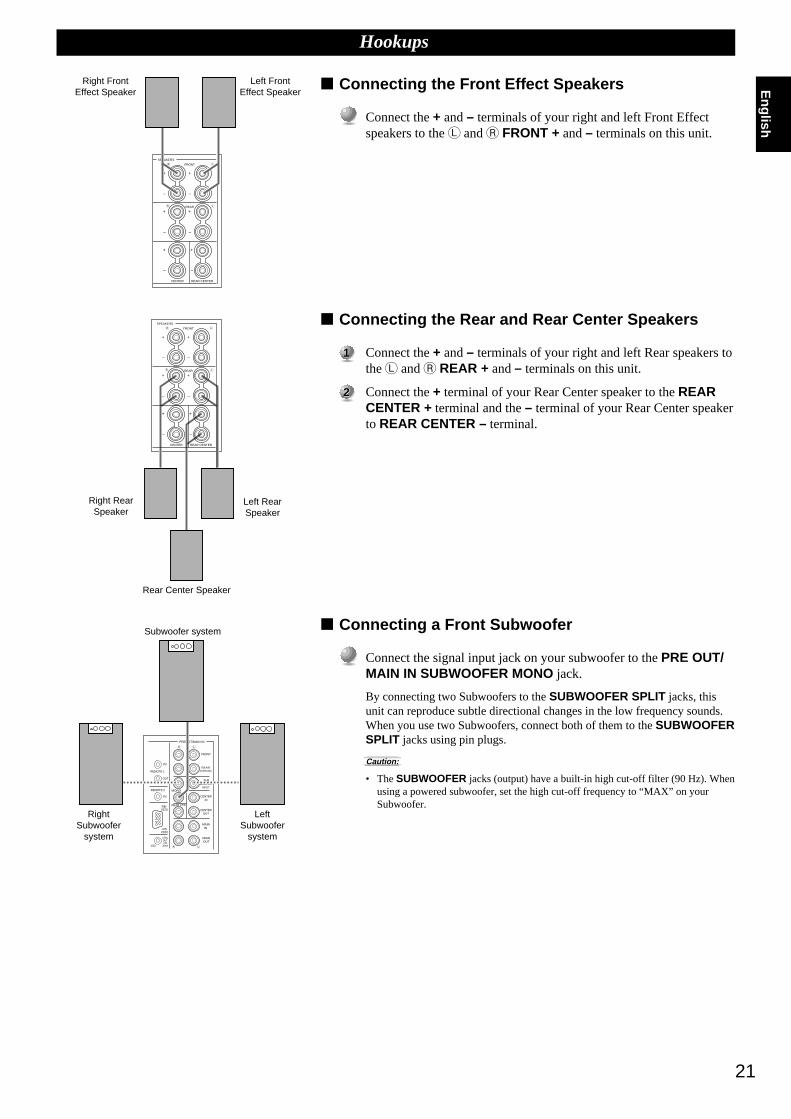
Connecting the Front Effect Speakers
Connect the + and – terminals of your right and left Front Effectspeakers to the L and R FRONT + and – terminals on this unit.
Connecting the Rear and Rear Center Speakers
11 Connect the + and – terminals of your right and left Rear speakers tothe L and R REAR + and – terminals on this unit.
22 Connect the + terminal of your Rear Center speaker to the REARCENTER + terminal and the – terminal of your Rear Center speakerto REAR CENTER – terminal.
Connecting a Front Subwoofer
Connect the signal input jack on your subwoofer to the PRE OUT/MAIN IN SUBWOOFER MONO jack.
By connecting two Subwoofers to the SUBWOOFER SPLIT jacks, thisunit can reproduce subtle directional changes in the low frequency sounds.When you use two Subwoofers, connect both of them to the SUBWOOFERSPLIT jacks using pin plugs.
Caution:
• The SUBWOOFER jacks (output) have a built-in high cut-off filter (90 Hz). Whenusing a powered subwoofer, set the high cut-off frequency to “MAX” on yourSubwoofer.
Hookups
SPEAKERS
FRONT
REAR
CENTER REAR CENTER
+
–
+
–
+
–
+
–
+
–
+
–
SPEAKERS
FRONT
REAR
CENTER REAR CENTER
+
–
+
–
+
–
+
–
+
–
+
–
Right FrontEffect Speaker
Left FrontEffect Speaker
Right RearSpeaker
Left RearSpeaker
Rear Center Speaker
Subwoofer system
RightSubwoofer
system
LeftSubwoofer
system

22
Pre
para
tio
ns
Hookups
Connecting a Rear SubwooferBy using both Front and Rear Subwoofers, the CINEMA-DSP sound fieldprograms can produce realistic movie effects with powerful, dynamic sound. Totake advantage of this dynamic sound, be sure to set the 1C. REAR L/R SP itemin the SET MENU to “LARGE” (see page 37), and connect your Rear speakersand Subwoofer as shown below.
11 Connect the right + input terminal on your Subwoofer to the REARR + terminal, and the right – input terminal on your Subwoofer tothe REAR R – terminal with speaker cords.
22 Connect the left + input terminal on your Subwoofer to the REARL + terminal, and the left – input terminal on your Subwoofer to theREAR L – terminal with speaker cords.
33 Connect your Rear speakers to the output terminals on the RearSubwoofer.
Be sure to connect the Rear speakers to the Subwoofer with the correctpolarity.
Note:
• Adjust the speaker volume for the Subwoofer with the controls on the Subwoofers,not on the DSP-AX1.
Impedance Selector switchSelect the position whose requirements your speaker system meets.
(Upper position)
Front Effect:The impedance of each speaker must be 6Ω or higher.
Rear: The impedance of each speaker must be 4Ω or higher.Rear Center:
The impedance of the speaker must be 4Ω or higher.Center: The impedance of the speaker must be 4Ω or higher.Main: If you use one pair of main speakers, the impedance of each
speaker must be 4Ω or higher.If you use two pairs of main speakers, the impedance of eachspeaker must be 8Ω or higher.
(Lower position)Front Effect:
The impedance of each speaker must be 8Ω or higher.Rear: The impedance of each speaker must be 8Ω or higher.Rear Center:
The impedance of the speaker must be 8Ω or higher.Center: The impedance of the speaker must be 8Ω or higher.Main: If you use one pair of main speakers, the impedance of each
speaker must be 8Ω or higher.If you use two pairs of main speakers, the impedance of eachspeaker must be 16Ω or higher.
SPEAKERS
FRONT
REAR
CENTER REAR CENTER
+
–
+
–
+
–
+
–
+
–
+
–
IMPEDANCE SELECTORSET BEFORE POWER ON
FRONTREARREAR CENTERCENTERMAIN A OR B A + B
FRONTREARREAR CENTERCENTERMAIN A OR B A + B
WARNINGDo not change the IMPEDANCESELECTOR switch setting while the powerto this unit is on, otherwise this unit may bedamaged.
IF THIS UNIT FAILS TO TURN ONWHEN THE STANDBY/ON SWITCH ISPRESSED:
The IMPEDANCE SELECTOR switchmay not be set to either end. If so, set theswitch to either end when this unit is in thestandby mode.
(General Model)
Right RearSpeaker
Left RearSpeaker
Subwoofersystem

23
English
Connecting External AmplifiersIf you want to increase the power output to the speakers, or want to use another amplifier, connect an external amplifier to the PRE OUT/MAIN IN terminals as follows.
~ MAIN jacksMAIN OUT jacks ..... Main channel line output jacks.
The signals output through these jacksare affected by BASS , TREBLE ,BALANCE , and BASS EXTENSIONsettings.
MAIN IN jacks .......... Line input to the DSP-AX1 Mainchannel amplifiers.
Ÿ CENTER jacksCENTER OUT jack . Center channel line output jacks.
CENTER IN jack ..... Line input to the DSP-AX1 Centerchannel amplifier.
! REAR CT jackRear Center channel line output jack.
PREOUT/MAIN IN
FRONT
REAR(SURROUND)
SUBWOOFER
SPLIT
CENTERIN
CENTEROUT
MAININ
MAINOUT
MONO
REAR CTR
Hookups
Note:
• When RCA pin plugs are connected to the PRE OUT/MAIN IN output jacks for output to external amplifiers, the corresponding internal amplifierswill be muted.
⁄ SUBWOOFER jacksSubwoofers reinforce very low frequencies.MONO ...................... Main, Center and Rear channel
frequencies below 90 Hz are outputthrough this jack. You can also directDTS and Dolby Digital LFE signals tothis output.
SPLIT ....................... The SPLIT jacks output stereoseparation for the Main and Rearchannels and a split mono signal for theCenter and LFE channels.
Adjust the volume level of the subwoofer with the control onthe subwoofer. Subwoofer volume cannot be adjusted fromthis unit. Depending on the settings in SET MENU items1. SPEAKER SET, 3A. LFE LEVEL and 4A. LFE LEVEL,some signals may not be output from the SUBWOOFERjacks.
@ FRONTFront Effect channel line output jacks.
¤ REAR (SURROUND)Rear channel line output jacks.

24
Pre
para
tio
ns
Connecting Power Supply Cords
Connecting the AC Power CordAfter completing all connections, plug the AC power cord into a convenient ACoutlet.
AC OUTLETSUse these to connect the power cords from your other components to this unit.The power to the switched outlets is controlled by this unit’s STANDBY/ON(SYSTEM POWER ON or STANDBY on the remote). These outlets willsupply power to any connected unit whenever this unit is turned on. Themaximum power (total power consumption of components) that can be connectedto AC OUTLETS is 100W.
VOLTAGE SELECTOR (General and China Models)The voltage selector on the rear panel of this unit must be set for your localvoltage before plugging into the AC main supply.
Voltages are 110/120/220/240 V AC, 50/60 Hz.
AC OUTLETS
IMPEDANCE SELECTOR
VOLTAGE SELECTOR
Hookups
Connecting an External DecoderThe DSP-AX1 is equipped with six additional input jacks (left and right MAIN, CENTER, left and right SURROUND and SUBWOOFER)for discrete multi-channel input from an external decoder, sound processor, or pre-amplifier.
Connect the output jacks on your external decoder to the 6CHINPUT jacks.
Be sure to match the left and right outputs to the left and right input jacks forthe main and surround channels.
To listen to the sound from your external decoder, press 6CH INPUT on thisunit or the remote control.
Note:
• When you select 6CH INPUT as the input source, this unit automatically turns offthe digital sound field processor, and you cannot listen to DSP programs.
MAIN
CENTER
SUB WOOFER
6CH INPUT
SURROUND
DVD
LD
VCR 1
D-TV
CBL/SAT ZONE 2 OUT VIDEO
OUT
DIGITAL
L R L RC C
(General Model)
Subwoofer Output
External Decoder
Center Output
Main OutputSurround Output
AC Power Cord
AC OUTLETS
VOLTAGESELECTOR

25
English
On-Screen Displays (OSD)
You can display the operation information for this unit on a video monitor. If you display the SET MENU and DSP sound field programparameter settings on a screen, it is much easier to see the available options and parameters than it is by reading this information on the frontpanel display.If a video source is being reproduced, the OSD is superimposed over the image.If a video source is not being reproduced (or the power of the source equipment is off), the OSD is shown on a blue background.
OSD ModesYou can change the amount of information the OSD shows.
Full Display .............. This mode always shows the sound field program parameter settings on thevideo monitor (see page 73).
Short Display ............ This mode briefly shows the same contents as the front panel display at thebottom of the screen, then disappears.
Display Off ............... This mode briefly shows the “DISPLAY OFF” message at the bottom of thescreen, then disappears. Afterwards, no changes to operations appear on thescreen except those of the ON SCREEN.
Notes:
• When you choose the Full Display mode, INPUT SELECTOR, VOLUME and someother types of operation information are displayed at the bottom of the screen in thesame format as the front panel display.
• The OSD signal is not output through the REC OUT Selector, and will not be recordedwith any video signal.
• The SET MENU, TEST DOLBY SUR and TEST DSP appear regardless of the OSDmode.
Selecting the OSD Mode
11 When you turn on the power, the video monitor and front paneldisplay shows the level of the main volume for a few seconds andthen switches to show the current sound field program.
22 Press ON SCREEN on the remote control repeatedly to change thedisplay mode.
The OSD mode changes in the following order: Full Display, ShortDisplay, and Display Off.
Caution:
• If you choose a video input source that has equipment connected to both the S VIDEOIN and composite VIDEO IN jacks, and both the S VIDEO OUT and compositeVIDEO OUT jacks are connected to a video monitor, the video signal is output to boththe S VIDEO OUT and VIDEO OUT jacks. However, the OSD is carried only on theS-video signal. If no video signal is input, the OSD is carried on both the S-video andcomposite video signals.
• If your video monitor is connected only to the COMPONENT VIDEO terminals ofthis unit, the OSD is not shown. Make sure to connect your video monitor to theCOMPONENT VIDEO terminal and either VIDEO or S VIDEO terminals if youwould like to see the OSD.
• Playing back video software that has an anti-copy signal or video signals with a lot ofnoise may produce unstable images.
PAL/NTSC Switch (For General and China Models)This unit is designed for use with both the NTSC and PAL television formats. Setthis switch to the position compatible with your TV.
ON SCREEN LEVEL
SLEEP TEST
PARAMETER
SET MENU
PAL
NTSC
Full Display
Short Display
ON SCREEN
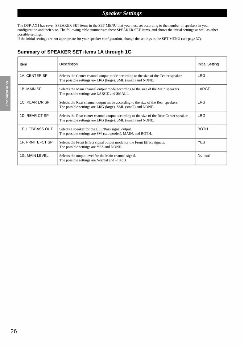
26
Pre
para
tio
ns
Speaker Settings
The DSP-AX1 has seven SPEAKER SET items in the SET MENU that you must set according to the number of speakers in yourconfiguration and their size. The following table summarizes these SPEAKER SET items, and shows the initial settings as well as otherpossible settings.If the initial settings are not appropriate for your speaker configuration, change the settings in the SET MENU (see page 37).
Summary of SPEAKER SET items 1A through 1G
Item
Selects the Center channel output mode according to the size of the Center speaker.The possible settings are LRG (large), SML (small) and NONE.
Selects the Main channel output mode according to the size of the Main speakers.The possible settings are LARGE and SMALL.
Selects the Rear channel output mode according to the size of the Rear speakers.The possible settings are LRG (large), SML (small) and NONE.
Selects the Rear center channel output according to the size of the Rear Center speaker.The possible settings are LRG (large), SML (small) and NONE.
Selects a speaker for the LFE/Bass signal output.The possible settings are SW (subwoofer), MAIN, and BOTH.
Selects the Front Effect signal output mode for the Front Effect signals.The possible settings are YES and NONE.
Selects the output level for the Main channel signal.The possible settings are Normal and –10 dB.
Initial SettingDescription
1A. CENTER SP
1B. MAIN SP
1C. REAR L/R SP
1D. REAR CT SP
1E. LFE/BASS OUT
1F. FRNT EFCT SP
1G. MAIN LEVEL
LRG
LARGE
LRG
LRG
BOTH
YES
Normal
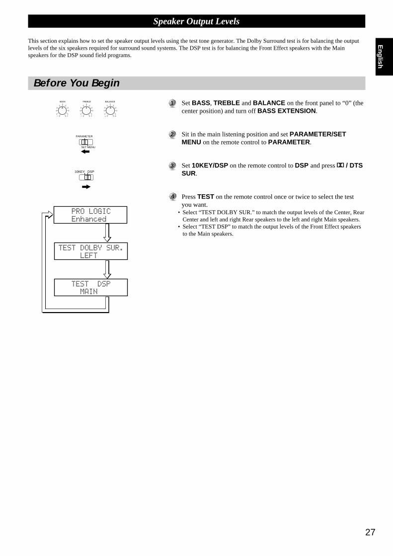
27
English
Before You Begin
11 Set BASS , TREBLE and BALANCE on the front panel to “0” (thecenter position) and turn off BASS EXTENSION .
22 Sit in the main listening position and set PARAMETER/SETMENU on the remote control to PARAMETER .
33 Set 10KEY/DSP on the remote control to DSP and press / DTSSUR.
44 Press TEST on the remote control once or twice to select the testyou want.
• Select “TEST DOLBY SUR.” to match the output levels of the Center, RearCenter and left and right Rear speakers to the left and right Main speakers.
• Select “TEST DSP” to match the output levels of the Front Effect speakersto the Main speakers.
Speaker Output Levels
This section explains how to set the speaker output levels using the test tone generator. The Dolby Surround test is for balancing the outputlevels of the six speakers required for surround sound systems. The DSP test is for balancing the Front Effect speakers with the Mainspeakers for the DSP sound field programs.
BASS TREBLE
5 54 4
3 3
2 21 1
0
+– 5 54 4
3 3
2 21 1
0
+– 5 54 4
3 3
2 21 1
0
RL
BALANCE
10KEY DSP
PARAMETER
SET MENU

28
Pre
para
tio
ns
Speaker Output Levels
Dolby Surround TestUse the Dolby Surround Test to balance the output levels of speakers required for surround sound systems.
11 Press TEST on the remote control so “TEST DOLBY SUR.”appears on the video monitor and front panel display.
22 Adjust VOLUME +/– so you can hear the test tone.
• The test tone is produced from the left Main speaker, Center speaker, rightMain speaker, right Rear speaker, Rear Center speaker and left Rearspeaker in order. The tone is produced for 2.5 seconds each time.
• You can stop the sequence temporarily by pressing % or
%
.
33 Adjust the output level of the effect speakers using the cursor – or +buttons on the remote control so the output level coming from eachspeaker is the same.
• You can increase the output levels of the effect channels (left Rear, rightRear, Rear Center and Center) to +10 dB. If the output level of the Center,Rear, and Rear Center speakers is lower than that from the Main speakerseven after you have increased the sound volume level of the Center, Rear,and Rear Center speakers up to +10 dB, set the 1G. MAIN LEVEL item inthe SET MENU to “–10dB.” Setting the 1G. MAIN LEVEL item to thissetting decreases the Main speaker volume level to about one-third thenormal level. After you set the 1G. MAIN LEVEL item in the SETMENU to “–10dB,” adjust the levels for the Center, Rear, and Rear Centerspeakers again.
44 When you finish adjusting the output level of the Center, Rear, andRear Center speakers, press TEST repeatedly until the current DSPprogram appears.
Note:
• The tonal quality of the speakers can be adjusted using the 7. CENTER GEQ, 8.REAR CT GEQ, and 9. CINEMA EQ items in the SET MENU (see page 45~46).
FLL
RL
C
RC
RFR
RR
TEST

29
English
11
22
33
44
Speaker Output Levels
DSP TestAdjust the output level of the Front Effect speakers while this unit is reproducing a DSP sound field program. If you do not use Front Effectspeakers, set the 1F. FRNT EFCT SP item in the SET MENU to “NONE” (see page 37), and the DSP Front Effect signals will be mixed withthe Main channel signals.
Press TEST repeatedly until “TEST DSP” appears on the videomonitor and front panel display.
Adjust VOLUME so you can hear the test tone.• The test tone is produced alternately from the Front Effect speakers and Main
speakers. The tone is produced for 2.5 seconds each time.
Adjust the output level of the Front Effect speakers using + and – so theoutput level coming from the Front Effect speakers is the same as thatof the Main speakers.• The test tone is automatically produced from the Front Effect speakers while
you are adjusting the level.
When you finish adjusting the output level of the Front Effect speakers,press TEST repeatedly until the current DSP program appears.
Notes:
• If you cannot hear the test tone, set VOLUME, turn off the power, and check thespeaker cords and hookups.
• The test tone can be reproduced separately from the left and right Front Effectspeakers. This is useful when you want to check the hookups to these speakers.Press % to reproduce the test tone from the left speaker, and press
%
to reproduce thetone from the right speaker. (The OSD shows which speaker is reproducing the tone.)
• You cannot adjust the output level of the left and right Front Effect speakers separately.
• You can stop the test tone’s alternation temporarily by pressing % or
%
.
• The tonal quality of the speakers can be adjusted using the 7. CENTER GEQ, 8. REARCT GEQ, and 9. CINEMA EQ items in the SET MENU (see page 45~46).
• If the sound volume of the Front Effect speakers is lower than that of the Mainspeakers, even after you have increased the output level up to +10 dB, set the 1G.MAIN LEVEL item in the SET MENU to “–10dB.” Setting the 1G. MAIN LEVELitem to “–10dB” decreases the Main speaker output level to about one-third of thenormal level.After you set the 1G. MAIN LEVEL item in the SET MENU to “–10dB,” repeat theTEST DOLBY SUR. procedure on the previous page.
TEST
FLL
RL
C
RC
RFR
RR
30
Basi
c O
pera
tio
n
Basic Operation
Basic Playback 31
Power Control ................................................................................................... 31Selecting a Source ............................................................................................. 32Input Modes and Indications ............................................................................. 33Selecting a Sound Field Program ...................................................................... 34
Basic Recording 35
Preparations ....................................................................................................... 35

31
English
Power Control
11 Press STANDBY/ON (or SYSTEM POWER on the remotecontrol) to turn on the power.
• The front panel (and the monitor screen) shows the level of the volume fora few seconds and then switches to show the current sound field program.
22 Press STANDBY/ON (or STANDBY on the remote control) to turnoff the power.
Note:
• This unit stores its current operational status in memory before the power is turnedoff. By connecting a commercially available timer to this unit, you can easilyplayback or record a source at any time you wish.
Basic Playback
PHONES BASS TREBLE
NATURAL SOUND AV AMPLIFIER DSP-AX1
INPUT MODE
INPUT SELECTOR
VOLUME
S VIDEO VIDEO L RAUDIO
VIDEO AUX
CINEMA DSP DOLBYD I G I T A L
D I G I T A L
S U R R O U N D
ON OFF5 54 4
3 3
2 21 1
0
+– 5 54 4
3 3
2 21 1
0
+– 5 54 4
3 3
2 21 1
0
RL
VCR 2 CDVCR 1 TUNER
CBL/SAT TAPED-TV MD
LD DVD
BALANCE
PHONOVCR 3VIDEO AUX
REC OUT/ZONE 2SOURCE/REMOTE
BASSEXTENSION
PROCESSORDIRECT
STANDBY/ON
6CH IMPUTSET MENU– + NEXT EFFECT PROGRAMSPEAKERSA B
TRANSMIT RE-NAME CLEARMACRO
MACROLEARN OFF ON
SYSTEMPOWER STANDBY V-AUX TAPE PHONO
D-TV CBL/SAT TUNER MD CD
VCR 1 VCR 2 VCR 3 LD DVD
6CH INPUT
TITLE
ENTER
MENU SOUNDDISPLAY
SOURCE
SELECT SEARCH CHAPTER
%
! !$
* #
$
%
%
%%%
10KEY DSP HALL 1 HALL 2 CHURCH JAZZ CLUB
ROCKCONCERT
ENTER-TAINMENT
CONCERTVIDEO 2
CONCERTVIDEO 1
POWER REC STOP PAUSE PLAY
6.1/ESTV
THEATERMOVIE
THEATER 2MOVIE
THEATER 1 /DTS
SUR.
0 +10 +100
1 2 3 4
5 6 7 8
9 10 11 12
+ + +TV VOL
A / B / C / D / E PRESET
TV INPUT
TV MUTE
CH
DISC
MUTE
EFFECT
VOLUME
+–
/
CHP/INDEX
– – –
STANDBY/ON
SYSTEMPOWER STANDBY
STANDBY/ON
SYSTEMPOWER STANDBY
EFFECT INPUT SELECTOR VOLUME
INPUT MODE
STANDBY/ONSTANDBY
SYSTEMPOWER
Inputbuttons
VOLUME
EFFECT
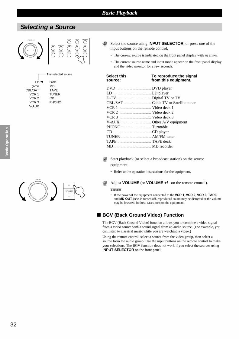
32
Basi
c O
pera
tio
n
Selecting a Source
11 Select the source using INPUT SELECTOR, or press one of theinput buttons on the remote control.
• The current source is indicated on the front panel display with an arrow.
• The current source name and input mode appear on the front panel displayand the video monitor for a few seconds.
DVD .................................. DVD playerLD ...................................... LD playerD-TV.................................. Digital TV or TVCBL/SAT ........................... Cable TV or Satellite tunerVCR 1 ................................ Video deck 1VCR 2 ................................ Video deck 2VCR 3 ................................ Video deck 3V-AUX .............................. Other A/V equipmentPHONO ............................. TurntableCD...................................... CD playerTUNER .............................. AM/FM tunerTAPE ................................. TAPE deckMD..................................... MD recorder
22 Start playback (or select a broadcast station) on the source
equipment.
• Refer to the operation instructions for the equipment.
33 Adjust VOLUME (or VOLUME +/– on the remote control).
Caution:
• If the power of the equipment connected to the VCR 1, VCR 2, VCR 3, TAPE,and MD OUT jacks is turned off, reproduced sound may be distorted or the volumemay be lowered. In these cases, turn on the equipment.
BGV (Back Ground Video) FunctionThe BGV (Back Ground Video) function allows you to combine a video signalfrom a video source with a sound signal from an audio source. (For example, youcan listen to classical music while you are watching a video.)
Using the remote control, select a source from the video group, then select asource from the audio group. Use the input buttons on the remote control to makeyour selections. The BGV function does not work if you select the sources usingINPUT SELECTOR on the front panel.
INPUT SELECTOR V-AUX TAPE PHONO
D-TV CBL/SAT TUNER MD CD
VCR 1 VCR 2 VCR 3 LD DVD
+VOLUME
–
VOLUME
Basic Playback
LDD-TV
CBL/SATVCR 1VCR 2VCR 3V-AUX
DVDMDTAPETUNERCDPHONO
Select thissource:
To reproduce the signalfrom this equipment.
The selected source

33
English
Basic Playback
Input Modes and Indications
AUTO
Dolby Digital RF
DTS
DIGITAL
ANALOG
The DSP-AX1 comes with various input jacks. If your external component is connected to more than one type of input jack, you can set thepriority of the input signal. Press INPUT MODE on the front panel or an input button (press it repeatedly) on the remote control to display orchange the input mode.
AUTO: ................. This mode is automatically selected when you turn on the power of thisunit. In this mode, the input signal is automatically selected in thefollowing order.
1) Dolby Digital or DTS encoded signals
2) Digital (PCM) signals
3) Analog signals
DTS: ..................... In this mode, only digital input signals encoded with DTS are selectedeven if other signals are input at the same time.
ANALOG: ........... In this mode, only analog input signals are selected even if digital signalsare input at the same time.
<When LD is selected as the input source>
AUTO: ................. In this mode, this unit automatically selects the signal in the followingorder.
1) Dolby Digital RF encoded signals
2) DTS encoded signals
3) Digital (PCM) signals
4) Analog signals
D.D. RF: ............... This unit only selects Dolby Digital RF signals.
DTS: ..................... This unit only selects DTS signals.
DGTL: .................. This unit only selects digital signals input through the OPTICAL jacks.
ANALOG: ........... This unit only selects signals input through the ANALOG jacks. This unitwill not select Dolby Digital RF or DTS signals.
Notes:
• For CD, DVD, and CBL/SAT sources, if digital signals are input from both theOPTICAL and COAXIAL terminals, the digital signal from the COAXIAL terminal isselected.
• When the “AUTO” mode is selected, the DSP-AX1 automatically determines the typeof signal. If the DSP-AX1 detects a DTS or Dolby Digital signal, the decoderautomatically switches to the appropriate setting and reproduces 5.1 channel sound.
• When you use functions such as pause, search, or disc change while playing a discencoded with DTS signals, the DTS indicator flashes until the next playback starts.
• If you play a disc encoded with DTS signals and the input mode is set to “ANALOG”,this unit reproduces the noise of an unprocessed DTS signal. When you want to play aDTS source, be sure to connect the source to a digital input jack and set the input modeto “AUTO” or “DTS.”
• If you switch the input mode to “ANALOG” while playing a disc encoded with DTSsignals, this unit reproduces no sound.
• For LD software that does not contain a digital soundtrack, connect the LD player tothe analog jacks and set the input mode to “AUTO” or “ANALOG.”
• The input mode resets to “AUTO” after you turn off the power. When the current inputsource is D-TV, CBL/SAT, and VCR 1, the input mode resets to the one set using the15. INPUT MODE item in the SET MENU after you turn off the power (see page 48).
• If the LD player is transmitting signals in a non-standard method, the DSP-AX1 cannotdetect the DTS or Dolby Digital signal. In this case, the decoder automatically switchesto PCM or analog.
• Some audio/video equipment, such as LD players, output different audio signalsthrough their analog and digital jacks. Change the input mode as necessary.
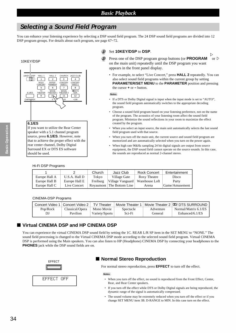
34
Basi
c O
pera
tio
n
10KEY DSP HALL 1 HALL 2 CHURCH JAZZ CLUB
ROCKCONCERT
ENTER-TAINMENT
CONCERTVIDEO 2
CONCERTVIDEO 1
6.1/ESTV
THEATERMOVIE
THEATER 2MOVIE
THEATER 1 /DTS
SUR.
0 +10 +100
1 2 3 4
5 6 7 8
9 10 11 12
CHP/INDEX
Selecting a Sound Field ProgramYou can enhance your listening experience by selecting a DSP sound field program. The 24 DSP sound field programs are divided into 12DSP program groups. For details about each program, see page 67~72.
11 Set 10KEY/DSP to DSP.
22 Press one of the DSP program group buttons (or PROGRAM%or
%
on the main unit) repeatedly until the DSP program you wantappears in the front panel display.
• For example, to select “Live Concert,” press HALL 2 repeatedly. You canalso select sound field programs within the current group by settingPARAMETER/SET MENU to the PARAMETER position and pressingthe cursor + or – button.
Notes:
• If a DTS or Dolby Digital signal is input when the input mode is set to “AUTO”,the sound field program automatically switches to the appropriate decodingprogram.
• Choose a sound field program based on your listening preference, not on the nameof the program. The acoustics of your listening room affect the sound fieldprogram. Minimize the sound reflections in your room to maximize the effectcreated by the program.
• When you select an input source, the main unit automatically selects the last soundfield program used with that source.
• When you turn off the main unit, the current source and sound field program arememorized and are automatically selected when you turn on the power again.
• When high rate 96kHz sampling 24 bit digital signals are output from sourceequipment, the DSP sound field cannot operate on the source sounds. In this case,the sounds are reproduced as normal 2-channel stereo.
Virtual CINEMA DSP and HP CINEMA DSPYou can experience the virtual CINEMA DSP sound field by setting the 1C. REAR L/R SP item in the SET MENU to “NONE.” Thesound field processing is changed to the Virtual CINEMA DSP mode according to the selected sound field program. Virtual CINEMADSP is performed using the Main speakers. You can also listen to HP (Headphone) CINEMA DSP by connecting your headphones to thePHONES jack while the DSP sound fields are on.
Normal Stereo ReproductionFor normal stereo reproduction, press EFFECT to turn off the effect.
Notes:
• When you turn off the effect, no sound is reproduced from the Front Effect, Center,Rear, and Rear Center speakers.
• If you turn off the effect while DTS or Dolby Digital signals are being reproduced, thedynamic range of the signal is automatically compressed.
• The sound volume may be extremely reduced when you turn off the effect or if youchange SET MENU item 3B. D-RANGE to MIN. In this case turn on the effect.
Basic Playback
1Europe Hall AEurope Hall BEurope Hall C
2U.S.A. Hall DEurope Hall ELive Concert
Rock ConcertRoxy Theatre
Warehouse LoftArena
ChurchTokyo
FreiburgRoyaumont
Jazz ClubVillage Gate
Village VanguardThe Bottom Line
EntertainmentDiscoParty
Game/Amusement
Hi-Fi DSP Programs
Concert Video 1Pop/Rock
DJ
Concert Video 2Classical/Opera
Pavilion
TV TheaterMono Movie
Variety/Sports
Movie Theater 1Spectacle
Sci-Fi
Movie Theater 2AdventureGeneral
/ DTS SURROUNDNormal/Matrix 6.1/ES
Enhanced/6.1/ES
CINEMA-DSP Programs
EFFECT
6.1/ESIf you want to utilize the Rear Centerspeaker with a 5.1 channel programsource, press 6.1/ES. However, notethat to achieve the proper effect with therear center channel, Dolby DigitalSurround EX or DTS ES softwareshould be used.
10KEY/DSP

35
English
REC OUT/ZONE 2 allows you to record one source while viewing and/or listening to another source.
Basic Recording
Preparations
11 Turn on the power to the DSP-AX1 and all connected equipment.
22 Select the source equipment you want to record using REC OUT/ZONE 2.
• To record the current source, set REC OUT/ZONE 2 to SOURCE/REMOTE.
• To record a source that you do not want to reproduce, set REC OUT/ZONE 2 to the source you want to record.
33 Start playback (or select a broadcast station) on the sourceequipment.
44 Start recording on the recording equipment
• If you want to listen to another source, and REC OUT/ZONE 2 is not setto SOURCE/REMOTE, select the source you want to reproduce withINPUT SELECTOR and adjust the volume.
Notes:
• Do a test recording before you start an actual recording.
• When this unit’s power is off, you cannot record between other equipmentconnected to this unit.
• Operating BASS and TREBLE , BASS EXTENSION , BALANCE , VOLUME,and DSP programs do not affect the recorded signal.
Caution:
• The RF (AC-3) input signal cannot be output using REC OUT/ZONE 2.
Special considerations when recording DTSsoftwareThe DTS signal is a digital bitstream. Attempting to digitally record the DTSbitstream will result in noise being recorded. Therefore, if you want to use thisunit to record sources that have DTS signals recorded on them, the followingconsiderations need to be made.
For DTS encoded LDs, DVDs, and CDs:Only 2-channel analog audio signals may be recorded as follows:
Laser Discs:Set your Laser Disc player’s left and right outputs to the analog soundtrack.
DVDs:Use the disc menu to set the DVD player’s mixed 2-channel left and right audiooutputs to the PCM or Dolby Digital soundtrack.
Compact Discs:The DTS signal recorded on CDs can only be output as a digital bitstream, andtherefore cannot be recorded.
VCR 2 CDVCR 1 TUNER
CBL/SAT TAPED-TV MD
LD DVD
PHONOVCR 3VIDEO AUX
REC OUT/ZONE 2SOURCE/REMOTE
STANDBY/ON

36
Ad
van
ced
Op
era
tio
n
Advanced Operation
SET MENU Items 37
Operating the SET MENU ................................................................................ 381. SPEAKER SET (1A. CENTER SP to 1G. MAIN LEVEL) ......................... 392. LOW FREQ. TEST ....................................................................................... 423. DOLBY D. SET (Dolby Digital Set) ............................................................ 434. DTS SET ....................................................................................................... 445. SP DELAY TIME ......................................................................................... 446. AUDIO DELAY ........................................................................................... 447. CENTER GEQ (Center Graphic Equalizer) ................................................. 458. REAR CT GEQ (Rear Center Graphic Equalizer) ....................................... 459. CINEMA EQ ................................................................................................ 4610. HP TONE CTRL (Headphone Tone Control) ............................................ 4711. PARAMETER INI (Parameter Initialization) ............................................ 4712. 6.1/ES AUTO .............................................................................................. 4713. MEMORY GUARD ................................................................................... 4814. CMPNT-V INPT (Component Video Input) .............................................. 4815. INPUT MODE ............................................................................................ 4816. INPUT RENAME ....................................................................................... 4917. DIMMER .................................................................................................... 4918. ZONE 2 SET ............................................................................................... 49
Remote Control Features 50
Using the Remote Control ................................................................................ 50Each Component Control Area ......................................................................... 52Operating a Tuner (TUNER Area) ................................................................... 52Operating a Tape Deck (TAPE Area) ............................................................... 52Operating a CD Player (CD Area) .................................................................... 53Operating an MD Recorder (MD Area) ............................................................ 53Operating an LD Player (LD Area) .................................................................. 54Operating a DVD Player (DVD Area) .............................................................. 54Operating a VCR (VCR 1 / VCR 2 / VCR 3 Area) .......................................... 55Operating a TV or Digital TV (D-TV Area) ..................................................... 55Operating a Cable or Satellite TV Tuner (CBSAT Area) ................................. 56Free Area (OPTN and PHONO Areas) ............................................................. 56Setting the Manufacturer Code in the Remote Control .................................... 57Programming a New Remote Control Function ............................................... 58Using the Macro Feature ................................................................................... 59Changing the Source Name in the Display Window ........................................ 61Clearing a Learned Function or Macro ............................................................. 61Clearing Learned Functions, Macros, Renamed Displays,and Manufacturer Setups .................................................................................. 62
Adjusting the Levels of the Effect Speakers 63
Setting the Sleep Timer 63
ZONE 2 64
Connections ....................................................................................................... 64Remote Control in ZONE 2 .............................................................................. 65
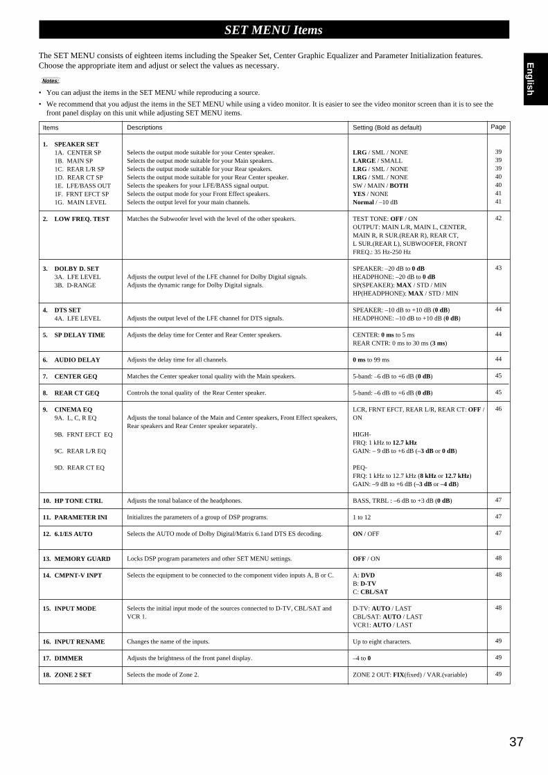
37
English
Items
1. SPEAKER SET1A. CENTER SP1B. MAIN SP1C. REAR L/R SP1D. REAR CT SP1E. LFE/BASS OUT1F. FRNT EFCT SP1G. MAIN LEVEL
2. LOW FREQ. TEST
3. DOLBY D. SET3A. LFE LEVEL3B. D-RANGE
4. DTS SET4A. LFE LEVEL
5. SP DELAY TIME
6. AUDIO DELAY
7. CENTER GEQ
8. REAR CT GEQ
9. CINEMA EQ9A. L, C, R EQ
9B. FRNT EFCT EQ
9C. REAR L/R EQ
9D. REAR CT EQ
10. HP TONE CTRL
11. PARAMETER INI
12. 6.1/ES AUTO
13. MEMORY GUARD
14. CMPNT-V INPT
15. INPUT MODE
16. INPUT RENAME
17. DIMMER
18. ZONE 2 SET
Descriptions
Selects the output mode suitable for your Center speaker.Selects the output mode suitable for your Main speakers.Selects the output mode suitable for your Rear speakers.Selects the output mode suitable for your Rear Center speaker.Selects the speakers for your LFE/BASS signal output.Selects the output mode for your Front Effect speakers.Selects the output level for your main channels.
Matches the Subwoofer level with the level of the other speakers.
Adjusts the output level of the LFE channel for Dolby Digital signals.Adjusts the dynamic range for Dolby Digital signals.
Adjusts the output level of the LFE channel for DTS signals.
Adjusts the delay time for Center and Rear Center speakers.
Adjusts the delay time for all channels.
Matches the Center speaker tonal quality with the Main speakers.
Controls the tonal quality of the Rear Center speaker.
Adjusts the tonal balance of the Main and Center speakers, Front Effect speakers,Rear speakers and Rear Center speaker separately.
Adjusts the tonal balance of the headphones.
Initializes the parameters of a group of DSP programs.
Selects the AUTO mode of Dolby Digital/Matrix 6.1and DTS ES decoding.
Locks DSP program parameters and other SET MENU settings.
Selects the equipment to be connected to the component video inputs A, B or C.
Selects the initial input mode of the sources connected to D-TV, CBL/SAT andVCR 1.
Changes the name of the inputs.
Adjusts the brightness of the front panel display.
Selects the mode of Zone 2.
Setting (Bold as default)
LRG / SML / NONELARGE / SMALLLRG / SML / NONELRG / SML / NONESW / MAIN / BOTHYES / NONENormal / –10 dB
TEST TONE: OFF / ONOUTPUT: MAIN L/R, MAIN L, CENTER,MAIN R, R SUR.(REAR R), REAR CT,L SUR.(REAR L), SUBWOOFER, FRONTFREQ.: 35 Hz-250 Hz
SPEAKER: –20 dB to 0 dBHEADPHONE: –20 dB to 0 dBSP(SPEAKER): MAX / STD / MINHP(HEADPHONE): MAX / STD / MIN
SPEAKER: –10 dB to +10 dB (0 dB)HEADPHONE: –10 dB to +10 dB (0 dB)
CENTER: 0 ms to 5 msREAR CNTR: 0 ms to 30 ms (3 ms)
0 ms to 99 ms
5-band: –6 dB to +6 dB (0 dB)
5-band: –6 dB to +6 dB (0 dB)
LCR, FRNT EFCT, REAR L/R, REAR CT: OFF /ON
HIGH-FRQ: 1 kHz to 12.7 kHzGAIN: – 9 dB to +6 dB (–3 dB or 0 dB)
PEQ-FRQ: 1 kHz to 12.7 kHz (8 kHz or 12.7 kHz)GAIN: –9 dB to +6 dB (–3 dB or –4 dB)
BASS, TRBL : –6 dB to +3 dB (0 dB)
1 to 12
ON / OFF
OFF / ON
A: DVDB: D-TVC: CBL/SAT
D-TV: AUTO / LASTCBL/SAT: AUTO / LASTVCR1: AUTO / LAST
Up to eight characters.
–4 to 0
ZONE 2 OUT: FIX (fixed) / VAR.(variable)
SET MENU Items
The SET MENU consists of eighteen items including the Speaker Set, Center Graphic Equalizer and Parameter Initialization features.Choose the appropriate item and adjust or select the values as necessary.
Notes:
• You can adjust the items in the SET MENU while reproducing a source.
• We recommend that you adjust the items in the SET MENU while using a video monitor. It is easier to see the video monitor screen than it is to see thefront panel display on this unit while adjusting SET MENU items.
Page
39393940404141
42
43
44
44
44
45
45
46
47
47
47
48
48
48
49
49
49
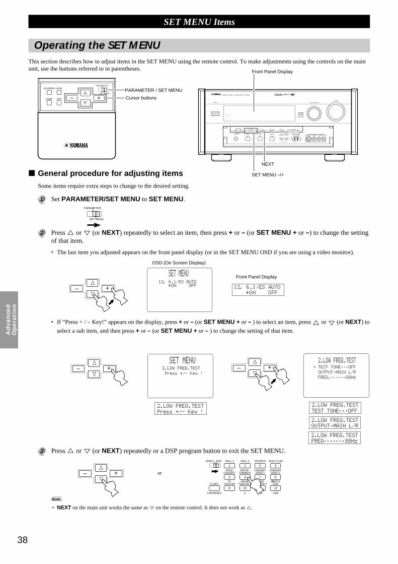
38
Ad
van
ced
Op
era
tio
n
SET MENU Items
General procedure for adjusting itemsSome items require extra steps to change to the desired setting.
11 Set PARAMETER/SET MENU to SET MENU.
22 Press % or
%
(or NEXT) repeatedly to select an item, then press + or – (or SET MENU + or –) to change the settingof that item.
• The last item you adjusted appears on the front panel display (or in the SET MENU OSD if you are using a video monitor).
• If “Press + / – Key!” appears on the display, press + or – (or SET MENU + or – ) to select an item, press % or % (or NEXT) to
select a sub item, and then press + or – (or SET MENU + or – ) to change the setting of that item.
33 Press % or
%
(or NEXT) repeatedly or a DSP program button to exit the SET MENU.
Note:
• NEXT on the main unit works the same as % on the remote control. It does not work as %.
ON SCREEN LEVEL
SLEEP TEST
PARAMETER
SET MENU%%
PARAMETER
SET MENU
PHONES BASS TREBLE
NATURAL SOUND AV AMPLIFIER DSP-AX1
INPUT MODE
POWER INPUT SELECTOR
VOLUME
S VIDEO VIDEO L RAUDIO
VIDEO AUX
CINEMA DSP DOLBYD I G I T A L
D I G I T A L
S U R R O U N D
ON OFF5 54 4
3 3
2 21 1
0
+– 5 54 4
3 3
2 21 1
0
+– 5 54 4
3 3
2 21 1
0
RL
VCR 2 CDVCR 1 TUNER
CBL/SAT TAPED-TV MD
LD DVD
BALANCE
PHONOVCR 3VIDEO AUX
REC OUT/ZONE 2SOURCE/REMOTE
BASSEXTENSION
PROCESSORDIRECT
STANDBY/ON
6CH IMPUTSET MENU– + NEXT EFFECT PROGRAMSPEAKERSA B
+– #@
Operating the SET MENUThis section describes how to adjust items in the SET MENU using the remote control. To make adjustments using the controls on the mainunit, use the buttons referred to in parentheses.
+– #@
10KEY DSP HALL 1 HALL 2 CHURCH JAZZ CLUB
ROCKCONCERT
ENTER-TAINMENT
CONCERTVIDEO 2
CONCERTVIDEO 1
6.1/ESTV
THEATERMOVIE
THEATER 2MOVIE
THEATER 1 /DTS
SUR.
0 +10 +100
1 2 3 4
5 6 7 8
9 10 11 12
CHP/INDEX
+– #@
+– #@
PARAMETER / SET MENU
Cursor buttons
Front Panel Display
Front Panel Display
OSD (On Screen Display)
SET MENU –/+
NEXT
or

39
English
SET MENU Items
Use this feature to select suitable output modes for your speaker configuration. You must set the output mode when you use a subwoofer.
1A. CENTER SP (Center Speaker Mode)By adding a Center speaker to your speaker configuration, the DSP-AX1 can provide good dialogue localization for many listeners andsuperior synchronization of sound and images. The OSD shows a large, small or no center speaker depending on how you set this item.The initial setting is “LRG”.
Select the “LRG” (Large) setting if you have a large Center speaker. The entire range of Center channel signals is sentto the Center speaker.
Select the “SML” (Small) setting if you have a small Center speaker. Center channel low frequency signals of 90 Hzand below are directed to the speakers selected with the 1E. LFE/BASS OUT item (see page 40).
Select the “NONE” setting if you do not have a Center speaker. All of the Center channel signals are directed to theleft and right Main speakers. The “NONE” position provides good dialogue localization for the person sitting in themain listening position.
1B. MAIN SP (Main Speaker Mode)The display shows small or large Main speakers depending on how you set this item. The initial setting is “LARGE”.
Select the “LARGE” setting if you have large Main speakers. The entire range of left and right Main channel signals isdirected to the left and right Main speakers.
Select the “SMALL” setting if you have small Main speakers. The Main channel low frequency signals of 90 Hz andbelow are directed to the speakers selected with the 1E. LFE/BASS OUT item (see page 40).
Note:
• When you select the “MAIN” setting for the 1E. LFE/BASS OUT item, the Main channel low frequency signals of 90 Hz and below are directedto the Main speakers even if you select the “SMALL” setting for the Main speaker mode. In this case, the OSD shows large Main speakers.
1C. REAR L/R SP (Rear Speaker Mode)The OSD shows large, small or no Rear speakers depending on how you set this item. The initial setting is “LRG”.
Select the “LRG” setting if you have large left and right Rear speakers or if you use a Rear Subwoofer (see page 22).The entire range of Rear channel signals is sent to the left and right Rear speakers.
Select the “SML” setting if you have small left and right Rear speakers. Rear channel low frequency signals of 90Hzand below are directed to the speakers selected with the 1E. LFE/BASS OUT item (see page 40).
Select the “NONE” setting if you do not have Rear speakers.
• In this case, Rear Center speaker will automatically be set to “NONE” and the 1D. REAR CT SP item will be skipped.
NoneSmallLarge
Large Small
Large Small None
1. SPEAKER SET (1A. CENTER SP to 1G. MAIN LEVEL)
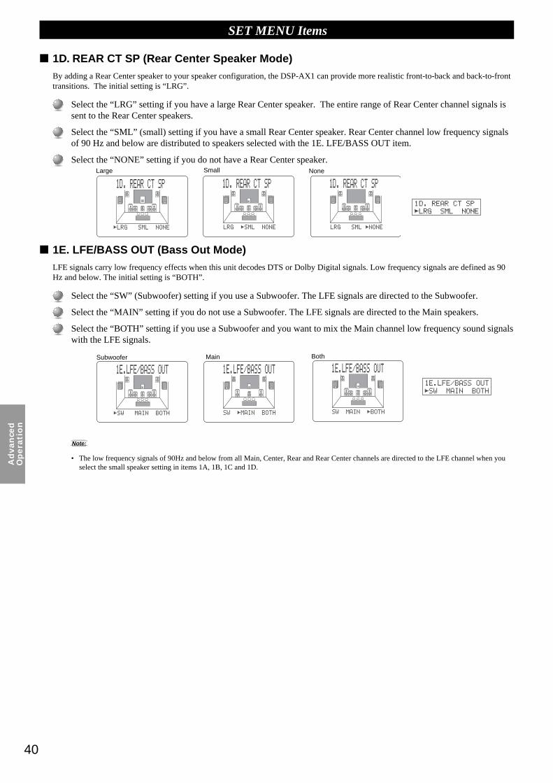
40
Ad
van
ced
Op
era
tio
n
1D. REAR CT SP (Rear Center Speaker Mode)By adding a Rear Center speaker to your speaker configuration, the DSP-AX1 can provide more realistic front-to-back and back-to-fronttransitions. The initial setting is “LRG”.
Select the “LRG” setting if you have a large Rear Center speaker. The entire range of Rear Center channel signals issent to the Rear Center speakers.
Select the “SML” (small) setting if you have a small Rear Center speaker. Rear Center channel low frequency signalsof 90 Hz and below are distributed to speakers selected with the 1E. LFE/BASS OUT item.
Select the “NONE” setting if you do not have a Rear Center speaker.
1E. LFE/BASS OUT (Bass Out Mode)LFE signals carry low frequency effects when this unit decodes DTS or Dolby Digital signals. Low frequency signals are defined as 90Hz and below. The initial setting is “BOTH”.
Select the “SW” (Subwoofer) setting if you use a Subwoofer. The LFE signals are directed to the Subwoofer.
Select the “MAIN” setting if you do not use a Subwoofer. The LFE signals are directed to the Main speakers.
Select the “BOTH” setting if you use a Subwoofer and you want to mix the Main channel low frequency sound signalswith the LFE signals.
Note:
• The low frequency signals of 90Hz and below from all Main, Center, Rear and Rear Center channels are directed to the LFE channel when youselect the small speaker setting in items 1A, 1B, 1C and 1D.
SET MENU Items
Large Small None
Subwoofer Main Both

41
English
1F. FRNT EFCT SP (Front Effect Speaker Mode)The DSP-AX1 uses Front Effect speakers to localize the virtual sound sources of the sound field programs. If you do not use Front Effectspeakers, you can direct the Front Effect signals to the Main speakers.
The OSD shows small or no Front Effect speakers depending on how you set this item. The initial setting is “YES”.
Select the “YES” setting if you use Front Effect speakers.
Select the “NONE” setting if you do not use Front Effect speakers. The Front Effect signals are mixed with the Mainchannels.
1G. MAIN LEVELChange this setting if you cannot match the sound volume of the Front, Rear, and Center speakers with the Main speakers because of theunusually high efficiency performance of the Main speakers. The initial setting is “Normal”.
Select the “Normal” setting if you can match the volume of your effect speakers with the volume of your Mainspeakers using the Dolby Surround Test (page 28).
Select the “–10dB” setting if you cannot match the volume of your effect speakers with the volume of your Mainspeakers using the Dolby Surround Test (page 28).
Note:
• When this unit decodes 96 kHz sampling/24 bit digital signals or 6CH INPUT is on, level adjustments in items 1A~1F are not possible.
SET MENU Items
YES NONE
Normal –10dB

42
Ad
van
ced
Op
era
tio
n
SET MENU Items
Use this feature to adjust the Subwoofer volume so it matches the volume of the other speakers in your configuration. Change the settingusing the remote control while sitting in the main listening position.
11 Press + or – (or SET MENU + or –) to set TEST TONE to “ON”, and adjust the volume using VOLUME + (orVOLUME) so you can hear the tone.
22 Press
%
(or NEXT) repeatedly to go to OUTPUT and press + or – (or SET MENU + or –) to select the speaker youwant to compare with the Subwoofer.
• If “SUBWOOFER” is selected, test tones above 90 Hz will not be output from the Subwoofer. The test tone will not necessarilybe output from the selected speakers. The output mode of the test tone depends on the settings of the 1. SPEAKER SET items inthe SET MENU.
33 Press
%
(or NEXT) repeatedly to go to FREQ. and press + or – (or SET MENU + or –) to select the frequency youwant to use.
44 Adjust the Subwoofer volume using the controls on the Subwoofer so it matches the volume of the speaker you arecomparing it to.
Notes:
• Do not turn up the VOLUME too high.
• If no test tone is heard, turn off the power and make sure all the necessary hookups are correct.
About the Test ToneThe test tone is produced by the tone generator.
The tone generator produces a narrow band noise centered at a specifiedfrequency by the band pass filter.
You can change the center frequency from 35 Hz through 250 Hz in one-sixthoctave steps.
You can use the test tone not only for adjusting the subwoofer level, but also forchecking the low frequency characteristics of your listening room. Low frequencysounds are especially affected by the listener’s position, speaker placement,subwoofer polarity and other conditions.
Digital Generator
(Wide Band Noise Produced)
Band Pass Filter
2. LOW FREQ. TEST
Center freq. 35 Hz~250 Hz
NOISE
FREQ.

43
English
SET MENU Items
3A. LFE LEVELUse this feature to adjust the output level of the LFE (low frequency effect) channel when playing back Dolby Digital encoded software.This setting is effective only when this unit decodes Dolby Digital signals. The LFE signal carries the low frequency special effect soundwhich is only added to certain scenes.
You can adjust the levels from 0 dB to –20 dB.
• Adjust the LFE levels according to the capacity of your subwoofer or headphones.
3B. D-RANGE (Dynamic Range)Use this feature to adjust the dynamic range. This setting is effective only when this unit decodes Dolby Digital signals.
Select the “MAX” setting for feature films.
Select the “STD” (Standard) setting for general use.
Select the “MIN” setting for listening to sources at extremely low volume levels.
Note:
• When D-RANGE is set to “MIN”, sound output may be faint because some Dolby Digital software is not compatible with the minimum leveldynamic range.
L-LEVEL BST
H-LEVEL CUT0.0
0.0
1.0
1.0
Dialogue level
Dialogue level
Dialogue level
MAX STD MIN
Out
put L
evel
Out
put L
evel
Out
put L
evel
Input Level Input Level Input Level
3. DOLBY D. SET (Dolby Digital Set)
Dialoguelevel
Dialoguelevel
Dialoguelevel

44
Ad
van
ced
Op
era
tio
nSET MENU Items
4A. LFE LEVELUse this feature to adjust the output level of the LFE (low frequency effect) channel when playing back DTS encoded software. Thissetting is effective only when this unit decodes DTS signals. The LFE signal carries the low frequency special effect sound which is onlyadded to certain scenes.
You can adjust the levels from –10 dB to +10 dB.
• Adjust the LFE level according to the capacity of your subwoofer or headphones.
5. SP DELAY TIMEUse this feature to adjust the delay of the Center and the Rear Center channel sounds. This feature works when this unit decodes DTS orDolby Digital signals. Ideally, the Center speaker and the Rear Center speaker should be the same distance from the main listening positionas the left and right Main speakers. However, in most home situations, the Center speaker or the Rear Center speaker is placed in line withthe Main speakers or the Rear speakers. By delaying the sound from the Center speaker and the Rear Center speaker, the apparent distancefrom the Center speaker and the Rear Center speaker to the main listening position can be adjusted to make it seem the same as the distancebetween the left and right Main speaker, and the left and right Rear speakers to the listening position. Adjusting the delay time for the Centerspeaker is especially important for giving depth to the dialogue.
You can adjust the delay time from 0 ms to 5 ms for the Center speaker and from 0 ms to 30 ms for the Rear Centerspeaker.
• Increasing the delay 1 ms simulates moving the speakers about 30 cm (one foot) farther away from the listening position.
6. AUDIO DELAYUse this feature to adjust the delay time of all channel sounds, when this unit decodes DTS or Dolby Digital signals. Adjusting AUDIODELAY is especially important for matching the sounds to screen pictures. Initial settings is “0ms”.
You can adjust the delay time from 0ms to 99ms.
L C
C
R
RL RC
RC
RR
4. DTS SET
Rear Center speaker image
Center speaker image
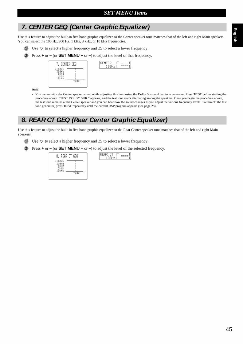
45
English
SET MENU Items
7. CENTER GEQ (Center Graphic Equalizer)Use this feature to adjust the built-in five band graphic equalizer so the Center speaker tone matches that of the left and right Main speakers.You can select the 100 Hz, 300 Hz, 1 kHz, 3 kHz, or 10 kHz frequencies.
11 Use
%
to select a higher frequency and % to select a lower frequency.
22 Press + or – (or SET MENU + or –) to adjust the level of that frequency.
Note:
• You can monitor the Center speaker sound while adjusting this item using the Dolby Surround test tone generator. Press TEST before starting theprocedure above. “TEST DOLBY SUR.” appears, and the test tone starts alternating among the speakers. Once you begin the procedure above,the test tone remains at the Center speaker and you can hear how the sound changes as you adjust the various frequency levels. To turn off the testtone generator, press TEST repeatedly until the current DSP program appears (see page 28).
8. REAR CT GEQ (Rear Center Graphic Equalizer)Use this feature to adjust the built-in five band graphic equalizer so the Rear Center speaker tone matches that of the left and right Mainspeakers.
11 Use
%
to select a higher frequency and % to select a lower frequency.
22 Press + or – (or SET MENU + or –) to adjust the level of the selected frequency.

46
Ad
van
ced
Op
era
tio
n
SET MENU Items
9. CINEMA EQUse this feature to match the tonal quality of four groups of speakers: the Main and Center speaker group, the Front Effect speakers group,the Rear speakers group, and the Rear Center speaker group. CINEMA-EQ consists of a high-shelving equalizer (HIGH) and a parametricequalizer (PEQ). The high-shelving equalizer changes high frequency characteristics, and the parametric equalizer boosts or cuts any selectedfrequency. The equalizer can be used for a variety of purposes, such as adjusting the tonal quality of differing types of speakers, adjusting thetonal quality in different installation environments, or adjusting the source sound to your liking.
The CINEMA EQ characteristic charts below show the value of the CINEMA EQ factory settings for each speaker group for generallistening conditions.
If you want to change the characteristics, follow the procedure below to adjust the frequency and gain for the high-shelving equalizer (HIGH)and parametric equalizer (PEQ). For the more detailed characteristics in different settings, see “CINEMA-EQ Frequency Characteristics” onpage 82.
11 Press
%
or% (or NEXT) repeatedly to select one of the speaker groups and press + (or SET MENU +) to select“ON”.
22 Press %
or% (or NEXT) repeatedly to select one of the following parameters, then press + or – (or SET MENU + or–) to change the setting of that parameter.
• Each time you press
%
(or NEXT ), the parameter changes on the front panel display as shown above. Press the cursor % to goin the reverse order.
Notes:
• When the 1F. FRNT EFCT SP item is set to “NONE”, the Front Effect signals are output from the Main speakers.
• CINEMA-EQ does not work when you press EFFECT to turn off the effect.
L.C.R. Preset ValueHIGH : FRQ 12.7 kHz GAIN –3 dBPEQ : FRQ 12.7 kHz GAIN –4 dB
PEQ
HIGH
HIGH+
PEQ
GAIN
FRQ
FRONT and REAR Preset ValueHIGH : FRQ 12.7 kHz GAIN 0dBPEQ : FRQ 8.0 kHz GAIN –3dB
+6
+3
0
–3
–6
–9
20 50 100 200 500 1k 2k 5k 10k 20k
PEQ
HIGHGAIN
FRQ
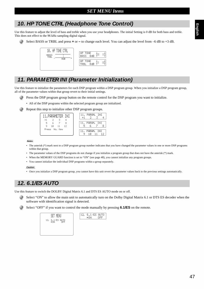
47
English
SET MENU Items
10. HP TONE CTRL (Headphone Tone Control)Use this feature to adjust the level of bass and treble when you use your headphones. The initial Setting is 0 dB for both bass and treble.This does not effect to the 96 kHz sampling digital signal.
Select BASS or TRBL and press + or – to change each level. You can adjust the level from –6 dB to +3 dB.
11. PARAMETER INI (Parameter Initialization)Use this feature to initialize the parameters for each DSP program within a DSP program group. When you initialize a DSP program group,all of the parameter values within that group revert to their initial settings.
Press the DSP program group button on the remote control for the DSP program you want to initialize.
• All of the DSP programs within the selected program group are initialized.
Repeat this step to initialize other DSP program groups.
Notes:
• The asterisk (*) mark next to a DSP program group number indicates that you have changed the parameter values in one or more DSP programswithin that group.
• The parameter values of the DSP programs do not change if you initialize a program group that does not have the asterisk (*) mark.
• When the MEMORY GUARD function is set to “ON” (see page 48), you cannot initialize any program groups.
• You cannot initialize the individual DSP programs within a group separately.
Caution:
• Once you initialize a DSP program group, you cannot have this unit revert the parameter values back to the previous settings automatically.
12. 6.1/ES AUTOUse this feature to switch the DOLBY Digital Matrix 6.1 and DTS ES AUTO mode on or off.
Select “ON” to allow the main unit to automatically turn on the Dolby Digital Matrix 6.1 or DTS ES decoder when thesoftware with identification signal is detected.
Select “OFF” if you want to control the mode manually by pressing 6.1/ES on the remote.

48
Ad
van
ced
Op
era
tio
n
SET MENU Items
13. MEMORY GUARDUse this feature to prevent accidental changes to DSP program parameter values and other settings on this unit.
Select “ON” to use MEMORY GUARD to protect the following features:
• DSP program parameters• All SET MENU items• Front, Rear, Center speaker and Subwoofer levels• The On-Screen Display mode
Notes:
• When MEMORY GUARD is “ON”, you cannot use any of the test modes.
• When MEMORY GUARD is “ON”, you cannot select any other SET MENU item.
14. CMPNT-V INPUT (Component Video Input)Use this feature to designate the input for each COMPONENT VIDEO terminal, A, B, and C. The initial settings are as written on the rearpanel. (Terminal A is for DVD, terminal B is for D-TV, and terminal C is for CBL/SAT.)
11 Select [A], [B], or [C] according to which terminal your equipment is connected to by pressing % or
%
.
22 Select the video input for your equipment by pressing + or –.
• You cannot select the same input once you have already selected it.
15. INPUT MODEUse this feature to designate the input mode for sources connected to D-TV, CBL/SAT and VCR 1 input jacks when you turn on this unit.
Select “AUTO” to allow this unit to automatically detect the type of input signal and select the appropriate inputmode.
Select “LAST” to set this unit to automatically select the last input mode used for that source.

49
English
SET MENU Items
16. INPUT RENAMEUse this feature to change the name of the input which appears on the OSD or the front panel display.
11 Select the input you want to change the name of by pressing an input button (or using INPUT SELECTOR).
22 Press + or – to place the under the space or the character you want to edit.
33 Press % or
%
to select the character you want to use and + or – to move to the next one.
• Press
%
to change the character in the following order, or press % to go in the reverse order.
A~Z, a space, 0~9, a space, a~z, a space, #, *, +, and so on.
• Follow the procedure above to rename other inputs.
44 Press + or – repeatedly to exit the INPUT RENAME mode.
17. DIMMER
You can adjust the brightness of the front panel display from –4 to 0.
18. ZONE 2 SETUse this feature to change the volume control setting for audio output to ZONE 2.
Selecting “VAR.” allows you to control the volume output to ZONE 2 with the remote control.
Select “FIX” when you don’t want to change the volume output to ZONE 2 with the remote control.

50
Ad
van
ced
Op
era
tio
n
Remote Control Features
The remote control can operate the main unit as well as other Yamaha audio and video components. To control the components of othermanufacturers (or some Yamaha), you must set up the remote control with the manufacturer’s codes. This remote control also has asophisticated Learn feature that allows it to acquire functions from the remote controls of other components in your system (or otherhousehold appliances) equipped with infrared remote control receivers. The Macro feature allows you to program a series of operations insequence onto a single button, or use the factory preset macros to operate other Yamaha components. These features make it possible for youto reduce the number of remote control units in your entertainment room.
Notes:
• For operating distance of the remote control and notes about batteries, refer to page 5.
• For the name and function of each part and button, refer to pages 8 and 9.
• If the memory in the remote control becomes full, no further learning is possible even if there are still some programmable buttons available.
Using the Remote Control
<Main Unit Control Area>The main unit control area is the shaded area shown below. It isfor controlling the DSP-AX1. You can use functions within thisarea no matter which Component Control Area is selected.
<Component Control Area>The component control area is the shaded area shown below. Eachcomponent has different functions for operation buttons in thecomponent control area. The component, which was chosen bypressing an input button, can be controlled and the displaywindow shows the corresponding name of the input.
TRANSMIT RE-NAME CLEARMACRO
MACROLEARN OFF ON
SYSTEMPOWER STANDBY V-AUX TAPE PHONO
D-TV CBL/SAT TUNER MD CD
VCR 1 VCR 2 VCR 3 LD DVD
6CH INPUT
TITLE
ENTER
MENU SOUNDDISPLAY
SOURCE
SELECT SEARCH CHAPTER
%
! !$
* #
$
%
%
%%%
10KEY DSP HALL 1 HALL 2 CHURCH JAZZ CLUB
ROCKCONCERT
ENTER-TAINMENT
CONCERTVIDEO 2
CONCERTVIDEO 1
POWER REC STOP PAUSE PLAY
EX/ESTV
THEATERMOVIE
THEATER 2MOVIE
THEATER 1
0 +10 +100
1 2 3 4
5 6 7 8
9 10 11 12
+ + +TV-VOL
A / B / C / D / E PRESET
TV INPUT
TV MUTE
CH
DISC
MUTE
EFFECT
VOLUME
+–
/
CHP/INDEX
– – –
TITLE
ENTER
MENU SOUNDDISPLAY
SEARCH CHAPTER
%
! !$
* #
$
%
%
%
10KEY DSP HALL 1 HALL 2 CHURCH JAZZ CLUB
ROCKCONCERT
ENTER-TAINMENT
CONCERTVIDEO 2
CONCERTVIDEO 1
POWER REC STOP PAUSE PLAY
EX/ESTV
THEATERMOVIE
THEATER 2MOVIE
THEATER 1
0 +10 +100
1 2 3 4
5 6 7 8
9 10 11 12
+ +TV-VOL
A / B / C / D / E PRESET
TV INPUT
TV MUTE
CH
DISC
+–
/
CHP/INDEX
– –
TITLE
ENTER
MENU SOUNDDISPLAY
SEARCH CHAPTER
%
! !$
* #
$
%
%%
10KEY DSP HALL 1 HALL 2 CHURCH JAZZ CLUB
ROCKCONCERT
ENTER-TAINMENT
CONCERTVIDEO 2
CONCERTVIDEO 1
POWER REC STOP PAUSE PLAY
6.1/ESTV
THEATERMOVIE
THEATER 2MOVIE
THEATER 1
0 +10 +100
1 2 3 4
5 6 7 8
9 10 11 12
+ +TV VOL
A / B / C / D / E PRESET
TV INPUT
TV MUTE
CH
DISC
+–
/
CHP/INDEX
– –
ON SCREEN LEVEL
SLEEP TEST
PARAMETER
SET MENU%%
TRANSMIT RE-NAME CLEARMACRO
MACROLEARN OFF ON
SYSTEMPOWER STANDBY V-AUX TAPE PHONO
D-TV CBL/SAT TUNER MD CD
VCR 1 VCR 2 VCR 3 LD DVD
6CH INPUT
TITLE
ENTER
MENU SOUNDDISPLAY
SOURCE
SELECT SEARCH CHAPTER
%
! !$
* #
$
%
%
%%%
10KEY DSP HALL 1 HALL 2 CHURCH JAZZ CLUB
ROCKCONCERT
ENTER-TAINMENT
CONCERTVIDEO 2
CONCERTVIDEO 1
POWER REC STOP PAUSE PLAY
6.1/ESTV
THEATERMOVIE
THEATER 2MOVIE
THEATER 1
0 +10 +100
1 2 3 4
5 6 7 8
9 10 11 12
+ + +TV VOL
A / B / C / D / E PRESET
TV INPUT
TV MUTE
CH
DISC
MUTE
EFFECT
VOLUME
+–
/
CHP/INDEX
– – –
Input selector
10KEY/DSP(DSP is selected)
Input selectorand switchingthe control areafor eachcomponent
10KEY/DSP(10KEY is selected)
There are 14 component control areas. You can setup the manufacturer code andprogram other remote control functions in each area (Cannot setup themanufacturer code in the OPTN area). See pages 57 and 58.
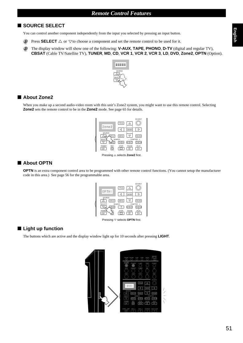
51
English
Remote Control Features
SOURCE SELECTYou can control another component independently from the input you selected by pressing an input button.
11 Press SELECT % or
%
to choose a component and set the remote control to be used for it.
22 The display window will show one of the following: V-AUX, TAPE, PHONO, D-TV (digital and regular TV),CBSAT (Cable TV/Satellite TV), TUNER, MD, CD, VCR 1, VCR 2, VCR 3, LD, DVD, Zone2 , OPTN (Option).
About Zone2When you make up a second audio-video room with this unit’s Zone2 system, you might want to use this remote control. SelectingZone2 sets the remote control to be in the Zone2 mode. See page 65 for details.
About OPTNOPTN is an extra component control area to be programmed with other remote control functions. (You cannot setup the manufacturercode in this area.) See page 56 for the programmable area.
Light up functionThe buttons which are active and the display window light up for 10 seconds after pressing LIGHT.
SOURCE
SELECT
%%
6CH INPUT
TITLE
ENTER
MENU SOUNDDISPLAY
SOURCE
SELECT SEARCH CHAPTER
%
! ! $
* #
$
%
%
%%%
POWER REC STOP PAUSE PLAY
+–
/
6CH INPUT
TITLE
ENTER
MENU SOUNDDISPLAY
SOURCE
SELECT SEARCH CHAPTER
%
! !$
* #
$
%
%
%%%
POWER REC STOP PAUSE PLAY
+–
/
TRANSMIT RE-NAME CLEARMACRO
MACROLEARN OFF ON
SYSTEMPOWER STANDBY V-AUX TAPE PHONO
D-TV CBL/SAT TUNER MD CD
VCR 1 VCR 2 VCR 3 LD DVD
6CH INPUT
TITLE
ENTER
MENU SOUNDDISPLAY
SOURCE
SELECT SEARCH CHAPTER
%
! !$
* #
$
%
%
%%%
10KEY DSP HALL 1 HALL 2 CHURCH JAZZ CLUB
POWER REC STOP PAUSE PLAY
1 2 3 4
+–
/
Pressing % selects Zone2 first.
Pressing fi selects OPTN first.
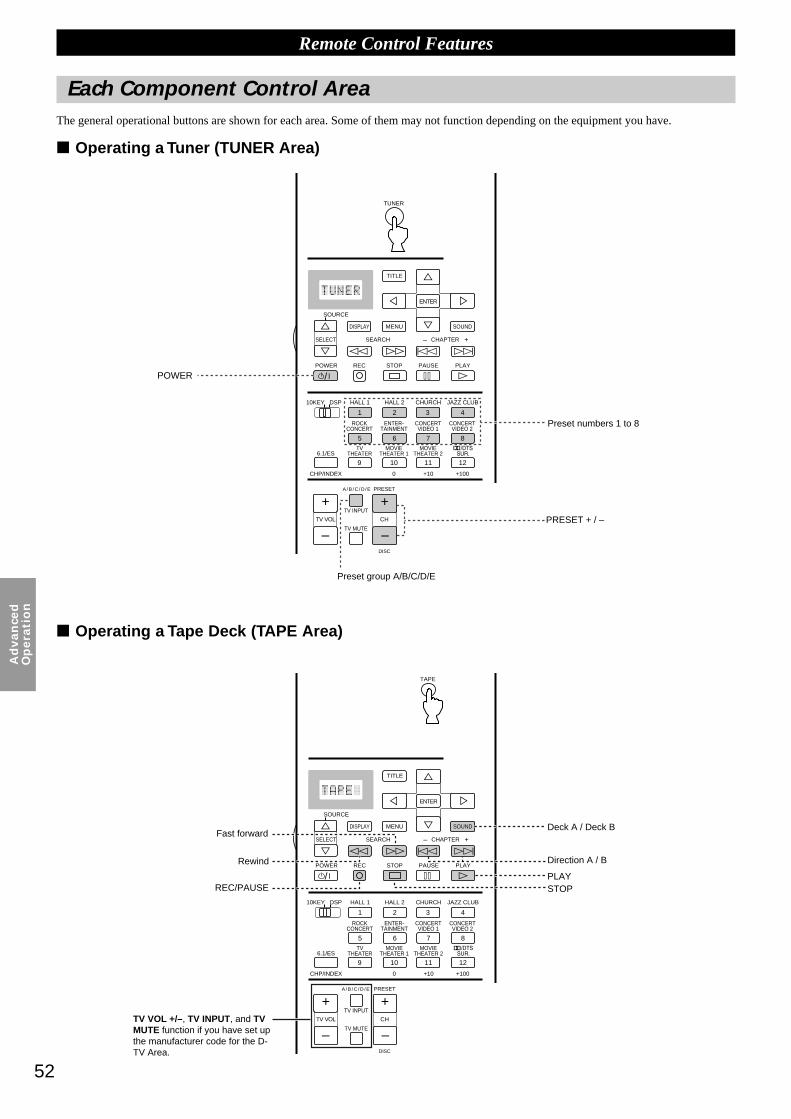
52
Ad
van
ced
Op
era
tio
n
Remote Control Features
Each Component Control AreaThe general operational buttons are shown for each area. Some of them may not function depending on the equipment you have.
Operating a Tuner (TUNER Area)
Operating a Tape Deck (TAPE Area)
SYSTEMPOWER STANDBY V-AUX TAPE PHONO
D-TV CBL/SAT TUNER MD CD
VCR 1 VCR 2 VCR 3 LD DVD
6CH INPUT
TITLE
ENTER
MENU SOUNDDISPLAY
SOURCE
SELECT SEARCH CHAPTER
%
! !$
* #
$
%
%
%%%
10KEY DSP HALL 1 HALL 2 CHURCH JAZZ CLUB
ROCKCONCERT
ENTER-TAINMENT
CONCERTVIDEO 2
CONCERTVIDEO 1
POWER REC STOP PAUSE PLAY
6.1/ESTV
THEATERMOVIE
THEATER 2MOVIE
THEATER 1
0 +10 +100
1 2 3 4
5 6 7 8
9 10 11 12
+ + +TV VOL
A / B / C / D / E PRESET
TV INPUT
TV MUTE
CH
DISC
MUTE
EFFECT
VOLUME
+–
/
CHP/INDEX
– – –
POWER
Preset numbers 1 to 8
Preset group A/B/C/D/E
Fast forward
Rewind
REC/PAUSE
TV VOL +/–, TV INPUT, and TVMUTE function if you have set upthe manufacturer code for the D-TV Area.
Deck A / Deck B
Direction A / B
PRESET + / –
PLAYSTOP
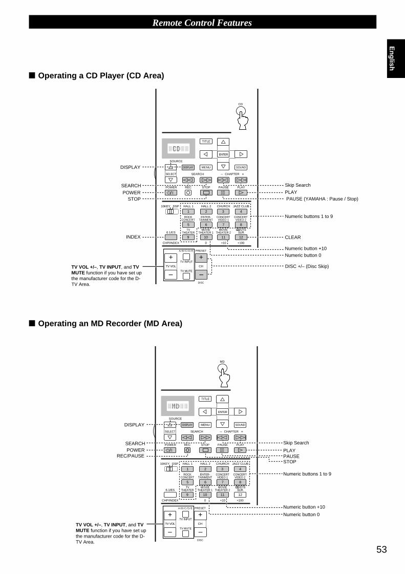
53
English
Remote Control Features
Operating a CD Player (CD Area)
Operating an MD Recorder (MD Area)
SYSTEMPOWER STANDBY V-AUX TAPE PHONO
D-TV CBL/SAT TUNER MD CD
VCR 1 VCR 2 VCR 3 LD DVD
6CH INPUT
TITLE
ENTER
MENU SOUNDDISPLAY
SOURCE
SELECT SEARCH CHAPTER
%
! !$
* #
$
%
%
%%%
10KEY DSP HALL 1 HALL 2 CHURCH JAZZ CLUB
ROCKCONCERT
ENTER-TAINMENT
CONCERTVIDEO 2
CONCERTVIDEO 1
POWER REC STOP PAUSE PLAY
6.1/ESTV
THEATERMOVIE
THEATER 2MOVIE
THEATER 1
0 +10 +100
1 2 3 4
5 6 7 8
9 10 11 12
+ ++
TV VOL
A / B / C / D / E PRESET
TV INPUT
TV MUTE
CH
DISC
MUTE
EFFECT
VOLUME
+–
/
CHP/INDEX
– – –
SYSTEMPOWER STANDBY V-AUX TAPE PHONO
D-TV CBL/SAT TUNER MD CD
VCR 1 VCR 2 VCR 3 LD DVD
6CH INPUT
TITLE
ENTER
MENU SOUNDDISPLAY
SOURCE
SELECT SEARCH CHAPTER
%
! !$
* #
$
%
%
%%%
10KEY DSP HALL 1 HALL 2 CHURCH JAZZ CLUB
ROCKCONCERT
ENTER-TAINMENT
CONCERTVIDEO 2
CONCERTVIDEO 1
POWER REC STOP PAUSE PLAY
6.1/ESTV
THEATERMOVIE
THEATER 2MOVIE
THEATER 1
0 +10 +100
1 2 3 4
5 6 7 8
9 10 11 12
+ + +TV VOL
A / B / C / D / E PRESET
TV INPUT
TV MUTE
CH
DISC
MUTE
EFFECT
VOLUME
+–
/
CHP/INDEX
– – –
TV VOL +/–, TV INPUT, and TVMUTE function if you have set upthe manufacturer code for the D-TV Area.
Skip Search
PAUSE (YAMAHA : Pause / Stop)
Numeric buttons 1 to 9
Numeric button +10Numeric button 0
DISC +/– (Disc Skip)
TV VOL +/–, TV INPUT, and TVMUTE function if you have set upthe manufacturer code for the D-TV Area.
REC/PAUSE
Numeric buttons 1 to 9
Numeric button +10
Numeric button 0
Skip Search
DISPLAY
SEARCH
STOPPOWER
INDEX
PLAY
CLEAR
DISPLAY
SEARCHPOWER PLAY
PAUSESTOP
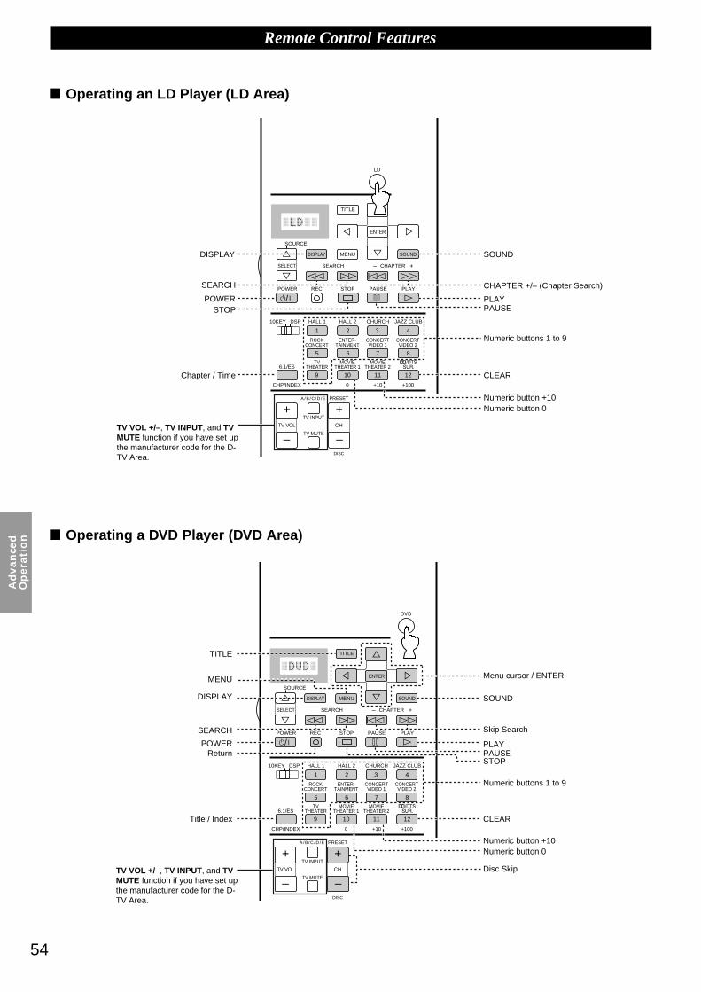
54
Ad
van
ced
Op
era
tio
n
Remote Control Features
Operating an LD Player (LD Area)
Operating a DVD Player (DVD Area)
SYSTEMPOWER STANDBY V-AUX TAPE PHONO
D-TV CBL/SAT TUNER MD CD
VCR 1 VCR 2 VCR 3 LD DVD
6CH INPUT
TITLE
ENTER
MENU SOUNDDISPLAY
SOURCE
SELECT SEARCH CHAPTER
%
! !$
* #
$
%
%
%%%
10KEY DSP HALL 1 HALL 2 CHURCH JAZZ CLUB
ROCKCONCERT
ENTER-TAINMENT
CONCERTVIDEO 2
CONCERTVIDEO 1
POWER REC STOP PAUSE PLAY
6.1/ESTV
THEATERMOVIE
THEATER 2MOVIE
THEATER 1
0 +10 +100
1 2 3 4
5 6 7 8
9 10 11 12
+ + +TV VOL
A / B / C / D / E PRESET
TV INPUT
TV MUTE
CH
DISC
MUTE
EFFECT
VOLUME
+–
/
CHP/INDEX
– – –
SYSTEMPOWER STANDBY V-AUX TAPE PHONO
D-TV CBL/SAT TUNER MD CD
VCR 1 VCR 2 VCR 3 LD DVD
6CH INPUT
TITLE
ENTER
MENU SOUNDDISPLAY
SOURCE
SELECT SEARCH CHAPTER
%
! !$
* #
$%
%
%%%
10KEY DSP HALL 1 HALL 2 CHURCH JAZZ CLUB
ROCKCONCERT
ENTER-TAINMENT
CONCERTVIDEO 2
CONCERTVIDEO 1
POWER REC STOP PAUSE PLAY
6.1/ESTV
THEATERMOVIE
THEATER 2MOVIE
THEATER 1
0 +10 +100
1 2 3 4
5 6 7 8
9 10 11 12
+ + +TV VOL
A / B / C / D / E PRESET
TV INPUT
TV MUTE
CH
DISC
MUTE
EFFECT
VOLUME
+–
/
CHP/INDEX
– – –TV VOL +/–, TV INPUT, and TVMUTE function if you have set upthe manufacturer code for the D-TV Area.
Chapter / Time
CHAPTER +/– (Chapter Search)
Numeric buttons 1 to 9
Numeric button +10Numeric button 0
Numeric buttons 1 to 9
Numeric button +10Numeric button 0
Return
Title / Index
TV VOL +/–, TV INPUT, and TVMUTE function if you have set upthe manufacturer code for the D-TV Area.
Skip Search
DISPLAY
SEARCH
POWERSTOP
SOUND
PLAYPAUSE
CLEAR
TITLE
MENU
DISPLAY
SEARCH
POWER
Menu cursor / ENTER
SOUND
PLAYPAUSESTOP
CLEAR
Disc Skip

55
English
Remote Control Features
Operating a VCR (VCR 1 / VCR 2 / VCR 3 Area)
Operating a TV or Digital TV (D-TV Area)
SYSTEMPOWER STANDBY V-AUX TAPE PHONO
D-TV CBL/SAT TUNER MD CD
VCR 1 VCR 2 VCR 3 LD DVD
6CH INPUT
TITLE
ENTER
MENU SOUNDDISPLAY
SOURCE
SELECT SEARCH CHAPTER
%
! !$
* #
$
%
%
%%%
10KEY DSP HALL 1 HALL 2 CHURCH JAZZ CLUB
ROCKCONCERT
ENTER-TAINMENT
CONCERTVIDEO 2
CONCERTVIDEO 1
POWER REC STOP PAUSE PLAY
6.1/ESTV
THEATERMOVIE
THEATER 2MOVIE
THEATER 1
0 +10 +100
1 2 3 4
5 6 7 8
9 10 11 12
+ + +TV VOL
A / B / C / D / E PRESET
TV INPUT
TV MUTE
CH
DISC
MUTE
EFFECT
VOLUME
+–
/
CHP/INDEX
– – –
SYSTEMPOWER STANDBY V-AUX TAPE PHONO
D-TV CBL/SAT TUNER MD CD
VCR 1 VCR 2 VCR 3 LD DVD
6CH INPUT
TITLE
ENTER
MENU SOUNDDISPLAY
SOURCE
SELECT SEARCH CHAPTER
%
! !$
* #
$%
%
%%%
10KEY DSP HALL 1 HALL 2 CHURCH JAZZ CLUB
ROCKCONCERT
ENTER-TAINMENT
CONCERTVIDEO 2
CONCERTVIDEO 1
POWER REC STOP PAUSE PLAY
6.1/ESTV
THEATERMOVIE
THEATER 2MOVIE
THEATER 1
0 +10 +100
1 2 3 4
5 6 7 8
9 10 11 12
+ + +TV VOL
A / B / C / D / E PRESET
TV INPUT
TV MUTE
CH
DISC
MUTE
EFFECT
VOLUME
+–
/
CHP/INDEX
– – –
Rewind /Fast Forward
TV VOL +/–, TV INPUT, and TVMUTE function if you have set upthe manufacturer code for the D-TV Area.
REC(Press twice)
Numeric buttons 1 to 9
Numeric button 10 or 0
You can control your VCR,if you have set up the code for VCR1.
Numeric buttons 1 to 9
Numeric button 10 or 0
Enter
POWER
TV / VIDEO
PLAYPAUSESTOP
CH +/–
DISPLAY
POWER
TV INPUT
TV VOL +/–
TV MUTE
CH +/–

56
Ad
van
ced
Op
era
tio
n
Remote Control Features
Operating a Cable or Satellite TV Tuner (CBSAT Area)
Free Area (OPTN and PHONO Areas)
6CH INPUT
TITLE
ENTER
MENU SOUNDDISPLAY
SOURCE
SELECT SEARCH CHAPTER
%
! !$
* #
$
%
%
%%%
10KEY DSP HALL 1 HALL 2 CHURCH JAZZ CLUB
ROCKCONCERT
ENTER-TAINMENT
CONCERTVIDEO 2
CONCERTVIDEO 1
POWER REC STOP PAUSE PLAY
6.1/ESTV
THEATERMOVIE
THEATER 2MOVIE
THEATER 1
0 +10 +100
1 2 3 4
5 6 7 8
9 10 11 12
+ + +TV VOL
A / B / C / D / E PRESET
TV INPUT
TV MUTE
CH
DISC
MUTE
EFFECT
VOLUME
+–
/
CHP/INDEX
– – –
SYSTEMPOWER STANDBY V-AUX TAPE PHONO
D-TV CBL/SAT TUNER MD CD
VCR 1 VCR 2 VCR 3 LD DVD
6CH INPUT
TITLE
ENTER
MENU SOUNDDISPLAY
SOURCE
SELECT SEARCH CHAPTER
%
! !$
* #
$%
%
%%%
10KEY DSP HALL 1 HALL 2 CHURCH JAZZ CLUB
ROCKCONCERT
ENTER-TAINMENT
CONCERTVIDEO 2
CONCERTVIDEO 1
POWER REC STOP PAUSE PLAY
6.1/ESTV
THEATERMOVIE
THEATER 2MOVIE
THEATER 1
0 +10 +100
1 2 3 4
5 6 7 8
9 10 11 12
+ + +TV VOL
A / B / C / D / E PRESET
TV INPUT
TV MUTE
CH
DISC
MUTE
EFFECT
VOLUME
+–
/
CHP/INDEX
– – –
You can control your VCR,if you have set up the code for VCR1.
Numeric buttons 1 to 9
Numeric button 0
Enter
Recall
Menu cursor / ENTER
TV VOL +/–, TV INPUT, and TVMUTE function if you have set upthe manufacturer code for the D-TV Area.
TV VOL +/–, TVINPUT, and TVMUTE function if youhave set up themanufacturer code forthe D-TV Area.
DISPLAYMENU
POWER
CH +/–
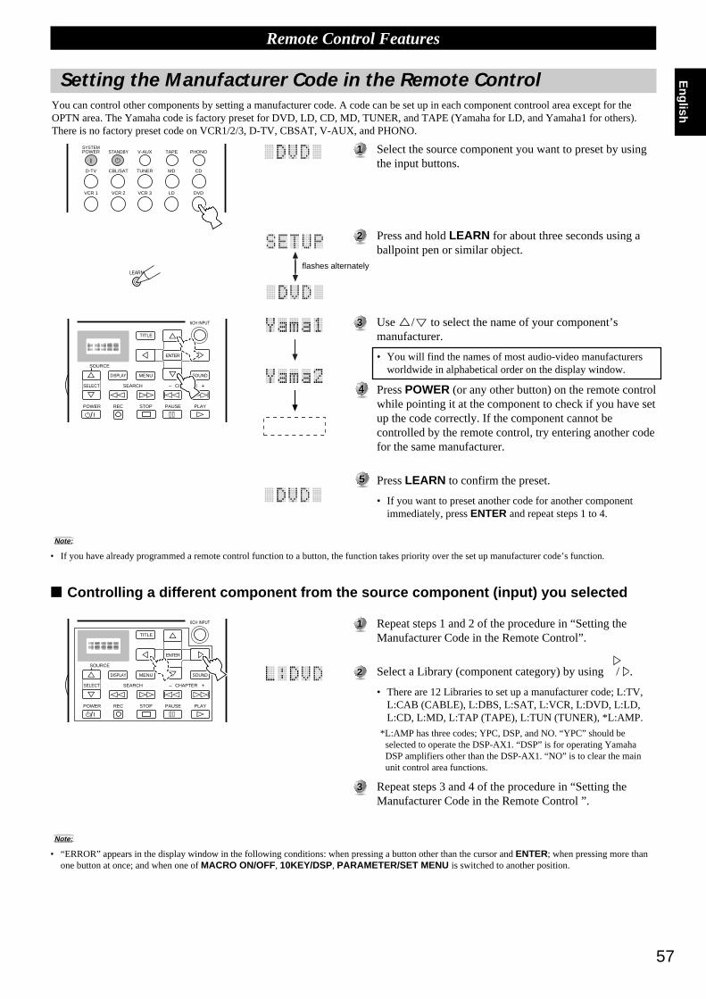
57
English
11 Select the source component you want to preset by usingthe input buttons.
22 Press and hold LEARN for about three seconds using aballpoint pen or similar object.
33 Use %/
%
to select the name of your component’smanufacturer.
• You will find the names of most audio-video manufacturersworldwide in alphabetical order on the display window.
44 Press POWER (or any other button) on the remote controlwhile pointing it at the component to check if you have setup the code correctly. If the component cannot becontrolled by the remote control, try entering another codefor the same manufacturer.
55 Press LEARN to confirm the preset.
• If you want to preset another code for another componentimmediately, press ENTER and repeat steps 1 to 4.
11 Repeat steps 1 and 2 of the procedure in “Setting theManufacturer Code in the Remote Control”.
22 Select a Library (component category) by using%/
%
.
• There are 12 Libraries to set up a manufacturer code; L:TV,L:CAB (CABLE), L:DBS, L:SAT, L:VCR, L:DVD, L:LD,L:CD, L:MD, L:TAP (TAPE), L:TUN (TUNER), *L:AMP.
*L:AMP has three codes; YPC, DSP, and NO. “YPC” should beselected to operate the DSP-AX1. “DSP” is for operating YamahaDSP amplifiers other than the DSP-AX1. “NO” is to clear the mainunit control area functions.
33 Repeat steps 3 and 4 of the procedure in “Setting theManufacturer Code in the Remote Control ”.
Remote Control Features
Setting the Manufacturer Code in the Remote Control
SYSTEMPOWER STANDBY V-AUX TAPE PHONO
D-TV CBL/SAT TUNER MD CD
VCR 1 VCR 2 VCR 3 LD DVD
LEARN
6CH INPUT
TITLE
ENTER
MENU SOUNDDISPLAY
SOURCE
SELECT SEARCH CHAPTER
POWER REC STOP PAUSE PLAY
+–
/
%
! !$
* #
$
%
%
%%%
6CH INPUT
TITLE
ENTER
MENU SOUNDDISPLAY
SOURCE
SELECT SEARCH CHAPTER
%
! !$
* #
$
%
%
%%%
POWER REC STOP PAUSE PLAY
+–
/
You can control other components by setting a manufacturer code. A code can be set up in each component controol area except for theOPTN area. The Yamaha code is factory preset for DVD, LD, CD, MD, TUNER, and TAPE (Yamaha for LD, and Yamaha1 for others).There is no factory preset code on VCR1/2/3, D-TV, CBSAT, V-AUX, and PHONO.
Note:
• If you have already programmed a remote control function to a button, the function takes priority over the set up manufacturer code’s function.
Controlling a different component from the source component (input) you selected
Note:
• “ERROR” appears in the display window in the following conditions: when pressing a button other than the cursor and ENTER; when pressing more thanone button at once; and when one of MACRO ON/OFF, 10KEY/DSP, PARAMETER/SET MENU is switched to another position.
flashes alternately

58
Ad
van
ced
Op
era
tio
n
Remote Control Features
Programming a New Remote Control FunctionIf you desire to program functions not included in the basic operations covered by the manufacturer code, or a manufacturer code is notavailable, the following procedure needs to be performed. The possible programming area is the same as a component control area, sobuttons are programmable independently for each source component area. It is also possible to program in the main unit control area.(Refer to page 50 for details on component control area and main unit control area.)
11 Place this remote control and the other remote controlabout 5 to 10 cm (2 to 4 in.) apart on a flat surface so thattheir infrared transmitters are aimed at each other.
22 Select a source component.
33 Press LEARN using a ball point pen or similar object.
44 Press and release the button where you want the newfunction to be programmed.
55 Press and hold the button on the other remote control thathas the function you want to program into this remotecontrol until “OK” appears in the display window.
• “NG” appears in display window when programming is notdone correctly.
66 Repeat Steps 4 and 5 to program additional functions.
77 Press LEARN again to exit the Learn mode.
LEARN
Notes:
• If you do not press any button within 30 seconds, the learning process is canceled.
• This remote control transmits infrared rays. If the other remote control also uses infrared rays, this remote control can learn most of the other remotecontrol’s functions. However, you may not be able to program some special signals or extremely long transmissions. (Refer to the operation instructions forthe other remote control.) When the memory is full, “FULL” appears in the display window, and this remote control cannot acquire any more functions.Clear unnecessary programmed functions to allow the unit to acquire new functions.
• Even if the batteries in the other remote control have enough power to transmit signals for operation, they may not have enough power to transmit signals tothis remote control.
• When the remote controls are either too close together or too far apart, you may not be able to program this remote control.
• Direct sunlight interferes with infrared rays.
• “ERROR” appears in the display window in the following conditions: when pressing more than one button at once; and when MACRO ON/OFF isswitched to another position.
TRANSMIT
RE-NAME
CLEARM
AC
RO
MACRO
LEARNO
FF
ON
SY
ST
EM
PO
WE
RS
TAN
DB
YV
-AU
XT
AP
EP
HO
NO
D-T
VC
BL/S
AT
TU
NE
RM
DC
D
VC
R 1
VC
R 2
VC
R 3
LDD
VD
6CH INPUT
TIT
LE%
%
%
TAPE
A/B
TRAN
SMIT
RE-N
AME
CLEAR
MA
CR
OM
ACR
OLEAR
NO
FF
ON
SY
ST
EM
PO
WE
RS
TAN
DB
YV
-AU
XT
AP
EP
HO
NO
D-T
VC
BL/S
AT
TU
NE
RM
DC
D
VC
R 1
VC
R 2
VC
R 3
LDD
VD
6CH
INPU
T
TIT
LE%
%
%
LEARN
TRAN
SMIT
RE-N
AME
CLEAR
MA
CR
OM
ACR
OLEAR
NO
FF
ON
SY
ST
EM
PO
WE
RS
TAN
DB
YV
-AU
XT
AP
EP
HO
NO
D-T
VC
BL/S
AT
TU
NE
RM
DC
D
VC
R 1
VC
R 2
VC
R 3
LDD
VD
6CH INPUT
TIT
LE%
%
%
5~10 cm (2 to 4 in.)
flashes alternately
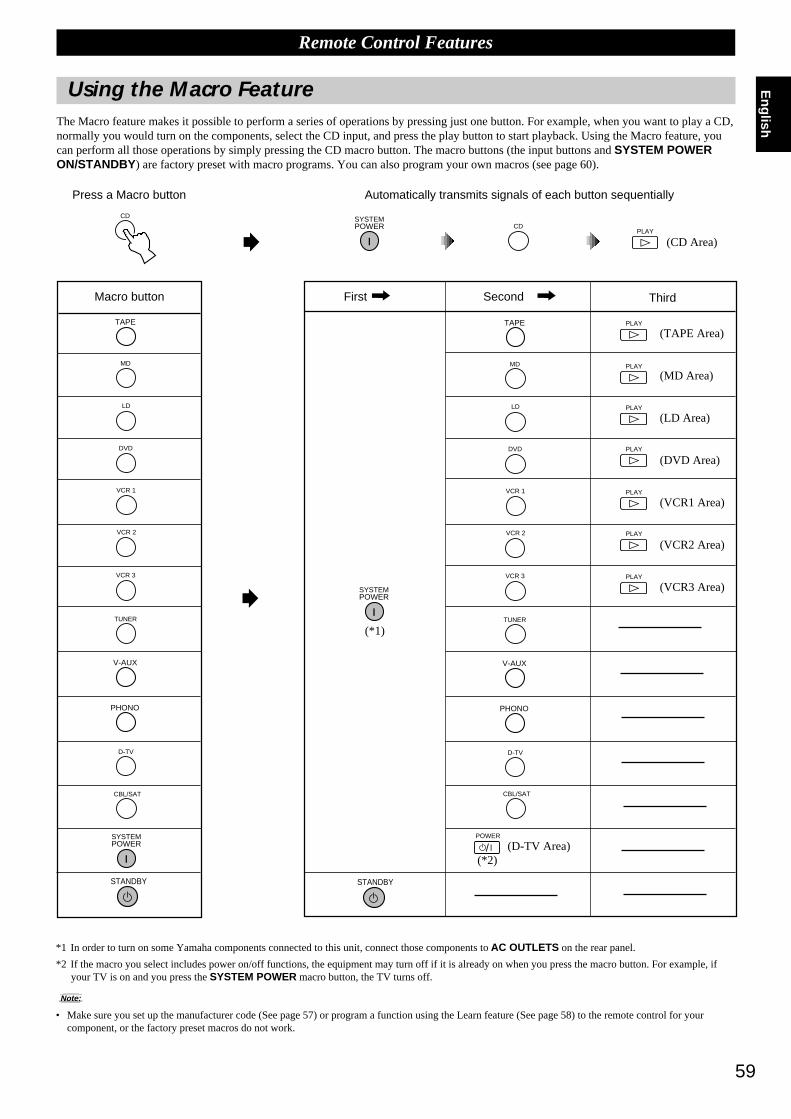
59
English
Using the Macro FeatureThe Macro feature makes it possible to perform a series of operations by pressing just one button. For example, when you want to play a CD,normally you would turn on the components, select the CD input, and press the play button to start playback. Using the Macro feature, youcan perform all those operations by simply pressing the CD macro button. The macro buttons (the input buttons and SYSTEM POWERON/STANDBY ) are factory preset with macro programs. You can also program your own macros (see page 60).
Remote Control Features
Macro button First Second Third
TUNER
SYSTEMPOWER
STANDBY
TAPE
CBL/SAT
MD
VCR 1
VCR 2
VCR 3
LD
DVD
V-AUX
PHONO
D-TV
SYSTEMPOWER
STANDBY
TUNER
TAPE
CBL/SAT
MD
VCR 1
VCR 2
VCR 3
LD
DVD
V-AUX
PHONO
D-TV
POWER
/
#PLAY
#PLAY
#PLAY
#PLAY
#PLAY
#PLAY
#PLAY
CD
Press a Macro button Automatically transmits signals of each button sequentially
*1 In order to turn on some Yamaha components connected to this unit, connect those components to AC OUTLETS on the rear panel.
*2 If the macro you select includes power on/off functions, the equipment may turn off if it is already on when you press the macro button. For example, ifyour TV is on and you press the SYSTEM POWER macro button, the TV turns off.
Note:
• Make sure you set up the manufacturer code (See page 57) or program a function using the Learn feature (See page 58) to the remote control for yourcomponent, or the factory preset macros do not work.
(*1)
(*2)(D-TV Area)
(TAPE Area)
(MD Area)
(LD Area)
(DVD Area)
(VCR1 Area)
(VCR2 Area)
(VCR3 Area)
SYSTEMPOWER
#PLAY
CD
(CD Area)
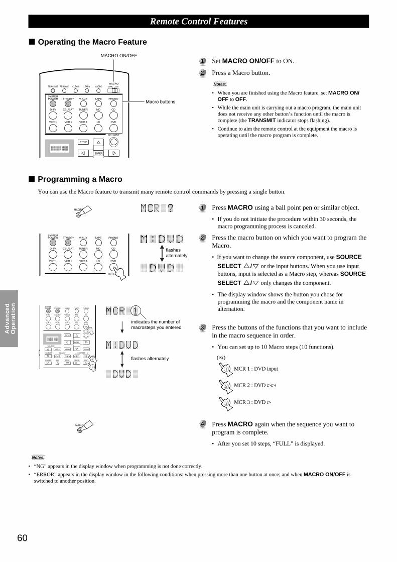
60
Ad
van
ced
Op
era
tio
n
11 Press MACRO using a ball point pen or similar object.
• If you do not initiate the procedure within 30 seconds, themacro programming process is canceled.
22 Press the macro button on which you want to program theMacro.
• If you want to change the source component, use SOURCE
SELECT %/
%
or the input buttons. When you use inputbuttons, input is selected as a Macro step, whereas SOURCE
SELECT %/%
only changes the component.
• The display window shows the button you chose forprogramming the macro and the component name inalternation.
33 Press the buttons of the functions that you want to includein the macro sequence in order.
• You can set up to 10 Macro steps (10 functions).
44 Press MACRO again when the sequence you want toprogram is complete.
• After you set 10 steps, “FULL” is displayed.
11 Set MACRO ON/OFF to ON.
22 Press a Macro button.
Notes:
• When you are finished using the Macro feature, set MACRO ON/OFF to OFF.
• While the main unit is carrying out a macro program, the main unitdoes not receive any other button’s function until the macro iscomplete (the TRANSMIT indicator stops flashing).
• Continue to aim the remote control at the equipment the macro isoperating until the macro program is complete.
MACRO
Remote Control Features
Notes:
• “NG” appears in the display window when programming is not done correctly.
• “ERROR” appears in the display window in the following conditions: when pressing more than one button at once; and when MACRO ON/OFF isswitched to another position.
MACRO
SYSTEMPOWER STANDBY V-AUX TAPE PHONO
D-TV CBL/SAT TUNER MD CD
VCR 1 VCR 2 VCR 3 LD DVD
6CH INPUT
TITLE
ENTER
MENU SOUNDDISPLAY
SOURCE
SELECT SEARCH CHAPTER
%
! !$
* #
$
%
%
%%%
POWER REC STOP PAUSE PLAY
+–
/
1
2
3
SYSTEMPOWER STANDBY V-AUX TAPE PHONO
D-TV CBL/SAT TUNER MD CD
VCR 1 VCR 2 VCR 3 LD DVD
6CH INPUT
1
2
3
Macro buttons
flashesalternately
indicates the number ofmacrosteps you entered
flashes alternately (ex)
MCR 1 : DVD input
MACRO ON/OFF
MCR 2 : DVD ›
MCR 3 : DVD #
Operating the Macro Feature
Programming a MacroYou can use the Macro feature to transmit many remote control commands by pressing a single button.
TRANSMIT RE-NAME CLEARMACRO
MACROLEARN OFF ON
SYSTEMPOWER STANDBY V-AUX TAPE PHONO
D-TV CBL/SAT TUNER MD CD
VCR 1 VCR 2 VCR 3 LD DVD
6CH INPUT
TITLE
ENTER
%
%
%

61
English
Changing the Source Name in the Display Window
Remote Control Features
11 Select the source component you want to rename by usingthe input buttons.
22 Press RE-NAME using a ballpoint pen or similar object.
33 Use the cursor buttons %/
%
to select a character.
• Pressing % changes the character in the following order:
A~Z, a~z, 0~9, space, -(hyphen).
44 Use the cursor buttons %/
%
to enter a character or moreto the next cursor postion.
55 Press RE-NAME to confirm renaming.
• If you want to rename another source component immediately,press ENTER and repeat steps 1, 3 and 4.
11 Select the source component that you want to clear on thewindow by using input buttons.
22 Press LEARN if you want to clear a learned function, orpress MACRO to clear a programmed macro, using a ballpoint pen or similar object.
33 Press and hold CLEAR using a ball point pen or similarobject, and at the same time press the button from whichyou want to clear the learned function or macro for about3 seconds.
• “C:NG” appears in the display window if the operation isunsuccessful. Should this occur, try doing step 3 again.
You can clear other learned functions and macros at this time bycontinuing to hold down CLEAR and pressing the other buttonson which those learned functions or macros are programmed.
44 Press LEARN again to confirm clearing a learnedfunction, or press MACRO again to confirm clearing aprogrammed macro.
• Once you clear a learned function or macro from a button, thebutton reverts to its factory preset function or macro.
Clearing a Learned Function or Macro
SYSTEMPOWER STANDBY V-AUX TAPE PHONO
D-TV CBL/SAT TUNER MD CD
VCR 1 VCR 2 VCR 3 LD DVD
CLEAR
MACRO
LEARN
SYSTEMPOWER STANDBY V-AUX TAPE PHONO
D-TV CBL/SAT TUNER MD CD
VCR 1 VCR 2 VCR 3 LD DVD
RE-NAME
SYSTEMPOWER STANDBY V-AUX TAPE PHONO
D-TV CBL/SAT TUNER MD CD
VCR 1 VCR 2 VCR 3 LD DVD
6CH INPUT
TITLE
ENTER
MENU SOUNDDISPLAY
SOURCE
SELECT SEARCH CHAPTER
%
! !$
* #
$
%
%
%%%
POWER REC STOP PAUSE PLAY
+–
/
RE-NAME
MACRO
LEARN
or
flashes alternately
flashesalternately
While pressing
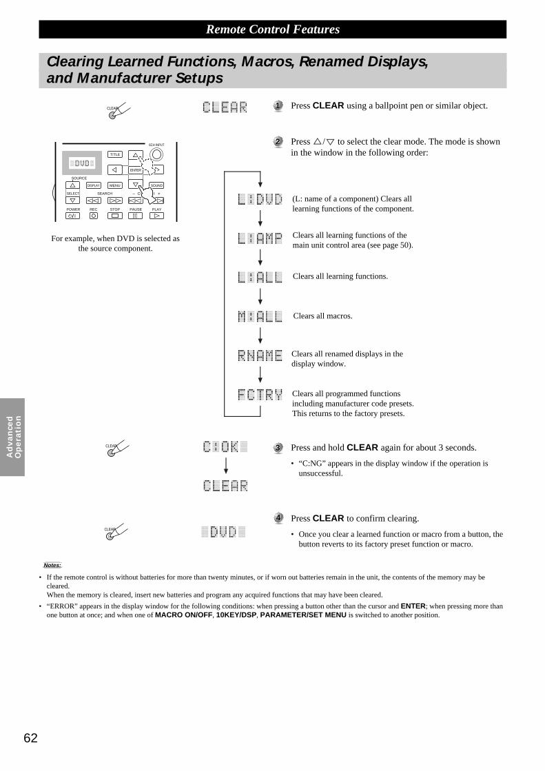
62
Ad
van
ced
Op
era
tio
n
11 Press CLEAR using a ballpoint pen or similar object.
22 Press %/
%
to select the clear mode. The mode is shownin the window in the following order:
Clearing Learned Functions, Macros, Renamed Displays,and Manufacturer Setups
Remote Control Features
Notes:
• If the remote control is without batteries for more than twenty minutes, or if worn out batteries remain in the unit, the contents of the memory may becleared.When the memory is cleared, insert new batteries and program any acquired functions that may have been cleared.
• “ERROR” appears in the display window for the following conditions: when pressing a button other than the cursor and ENTER; when pressing more thanone button at once; and when one of MACRO ON/OFF, 10KEY/DSP, PARAMETER/SET MENU is switched to another position.
6CH INPUT
TITLE
ENTER
MENU SOUNDDISPLAY
SOURCE
SELECT SEARCH CHAPTER
%
! !$
* #
$
%
%
%%%
POWER REC STOP PAUSE PLAY
+–
/
CLEAR
CLEAR
CLEAR
For example, when DVD is selected asthe source component.
33 Press and hold CLEAR again for about 3 seconds.
• “C:NG” appears in the display window if the operation isunsuccessful.
44 Press CLEAR to confirm clearing.
• Once you clear a learned function or macro from a button, thebutton reverts to its factory preset function or macro.
Clears all programmed functionsincluding manufacturer code presets.This returns to the factory presets.
(L: name of a component) Clears alllearning functions of the component.
Clears all learning functions of themain unit control area (see page 50).
Clears all learning functions.
Clears all macros.
Clears all renamed displays in thedisplay window.

63
English
Setting the Sleep Timer
Use this feature to automatically turn off the main unit after the amount of time you set. The Sleep Timer is useful when you plan to fallasleep while the main unit is reproducing or recording a source. The Sleep Timer also automatically turns off external components connectedto AC OUTLETS . The Sleep Timer can only be set using the remote control.
To set the Sleep Timer
11 Select a source using INPUT SELECTOR and start playback (orselect a broadcast station) on the source component.
22 Press SLEEP repeatedly to set the amount of time before the mainunit automatically turns off.
Each time you press SLEEP, the front panel display changes as shownbelow. After a few seconds the display returns to the previous indication.
= SLEEP 120 min = SLEEP 90 minSLEEP OFF + SLEEP 30 min + SLEEP 60 min+
To cancel the Sleep Timer
11 Press SLEEP repeatedly until “SLEEP OFF” appears in the frontpanel display.
After a few seconds, the display returns to the previous indication.
Note:
• The Sleep Timer setting can also be canceled by turning off the main unit usingSTANDBY on the remote control (or STANDBY/ON on the front panel) ordisconnecting the AC Power Cord from the AC outlet.
ON SCREEN LEVEL
SLEEP TEST
PARAMETER
SET MENU%%
Adjusting the Levels of the Effect Speakers
ON SCREEN LEVEL
SLEEP TEST
PARAMETER
SET MENU%%
You can adjust the volume level of each effect speaker (Center, Right Rear, Rear Center, Left Rear, Front Effect, and Subwoofer) whilelistening to a music source.
11 Set PARAMETER/SET MENU to PARAMETER .
22 Press LEVEL to select the speaker(s) you want to adjust.
Each time you press this button the selected speaker changes and appears inthe front panel display only as follows: Center, Right Rear, Rear Center, LeftRear, Front Effect Speakers, and Subwoofer
33 Adjust the speaker volume level using the + or – on the remotecontrol.
You can adjust the Center, Right Rear, Rear Center, Left Rear, Front EffectSpeakers from +10 dB to –10 dB.
You can adjust the Subwoofer from 0 dB down to –20 dB.
Notes:
• You cannot adjust the left and right speakers independently.
• When you adjust the speaker level using LEVEL , the settings you made using theDolby Surround Test and DSP Test change.
• When PARAMETER/SET MENU is set to SET MENU, you cannot adjust thespeaker level using LEVEL . However, each time you press LEVEL the currentlevel setting of each speaker appears. Select the speaker level you want to checkusing % or
%
.
Center
Right Rear
Rear Center
Left Rear
Front
Subwoofer

64
Ad
van
ced
Op
era
tio
n
ZONE 2
You can make up a multi-room audio-video system with this unit. With this feature, you can set this unit to reproduce separate input sourcesin the main room and second (Zone 2) room using the supplied remote control in the second room.
ONLY ANALOG SIGNALS ARE SENT TO THE SECOND ROOM. FOR ANY SOURCE YOU WISH TO LISTENTO IN THE SECOND ROOM, YOU MUST CONNECT THE ANALOG OUTPUT FROM THE SOURCE TO THECORRESPONDING ANALOG INPUT ON THIS UNIT.
ConnectionsTo use the multi-room functions of this unit, you need the following additional equipment:
• An infrared signal receiver in the second room
• An infrared emitter in the main room
This emitter transmits the infrared signals from the remote control in the second room to the main room
(for example, to a CD player or LD player).
• An amplifier and speakers for the second room
• A video monitor for the second room
Notes:
• Since there are so many ways to connect and use this unit in a multi-room installation,we recommend that you consult with a custom installation specialist for the Zone 2connections which will best meet your requirements.
• Some Yamaha models are able to connect directly to the REMOTE 1 OUT jacks ofthis unit. If you own these products, you may not need to use an infrared emitter. Up tosix Yamaha components can be connected as shown.
A sample of system configuration and connections
Special considerations when using DTS softwareThe DTS signal is a digital bitstream. Therefore, if you attempt to send the DTS signal to Zone 2, you will only be able to hear the digitalnoise that could damage your loudspeakers.
Due to this characteristic of DTS encoded discs, the following considerations and adjustments need to be made.
For DTS encoded LDs or DVDs
Only 2-channel audio signals may be sent to Zone 2, as follows:
• Laser disc – Set your Laser Disc player’s left and right outputs to the analog sound track.
• DVD disc – Use the disc menu to set the DVD player’s mixed 2-channel left and right audio outputs to PCM or Dolby Digital.
For DTS encoded compact discs
DO NOT USE the Zone 2 feature with DTS encoded compact discs.
OUT OUTRemote 1
OUTIN IN
This Unit
Main Room
DVD Player(or other component)
Infrared emitter
This Unit
Second Room
AmplifierVideo monitor
Remote control(in the Zone 2 mode)
Infrared signal receiver
REMOTE 1 OUT
VIDEO SIGNAL ZONE 2 OUT
REMOTE 1 IN
AUDIO SIGNAL ZONE 2 OUT
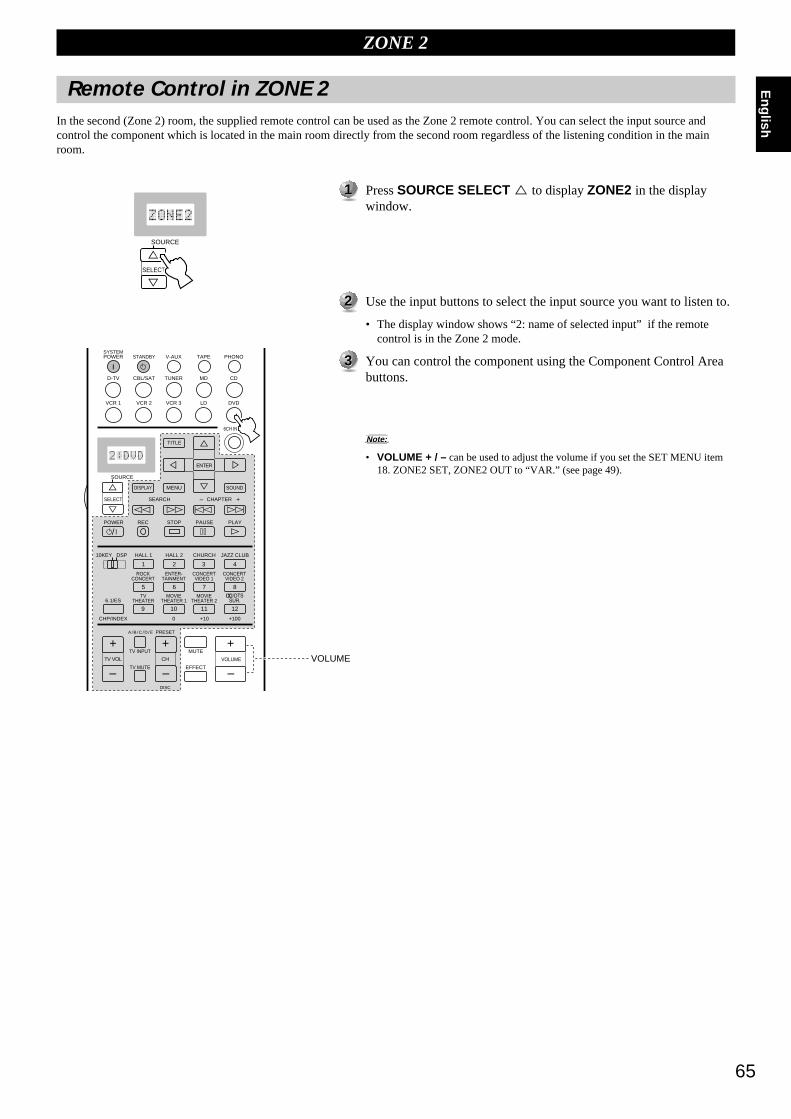
65
English
Remote Control in ZONE 2In the second (Zone 2) room, the supplied remote control can be used as the Zone 2 remote control. You can select the input source andcontrol the component which is located in the main room directly from the second room regardless of the listening condition in the mainroom.
11 Press SOURCE SELECT % to display ZONE2 in the displaywindow.
22 Use the input buttons to select the input source you want to listen to.
• The display window shows “2: name of selected input” if the remotecontrol is in the Zone 2 mode.
33 You can control the component using the Component Control Areabuttons.
Note:
• VOLUME + / – can be used to adjust the volume if you set the SET MENU item18. ZONE2 SET, ZONE2 OUT to “VAR.” (see page 49).
DISPLAY
SOURCE
SELECT SEAR
!
%%
ZONE 2
SYSTEMPOWER STANDBY V-AUX TAPE PHONO
D-TV CBL/SAT TUNER MD CD
VCR 1 VCR 2 VCR 3 LD DVD
6CH INPUT
TITLE
ENTER
MENU SOUNDDISPLAY
SOURCE
SELECT SEARCH CHAPTER
%
! !$
* #
$
%
%
%%%
10KEY DSP HALL 1 HALL 2 CHURCH JAZZ CLUB
ROCKCONCERT
ENTER-TAINMENT
CONCERTVIDEO 2
CONCERTVIDEO 1
POWER REC STOP PAUSE PLAY
6.1/ESTV
THEATERMOVIE
THEATER 2MOVIE
THEATER 1
0 +10 +100
1 2 3 4
5 6 7 8
9 10 11 12
+ + +TV VOL
A / B / C / D / E PRESET
TV INPUT
TV MUTE
CH
DISC
MUTE
EFFECT
VOLUME
+–
/
CHP/INDEX
– – –VOLUME

66
Ad
dit
ion
al
Info
rmati
on
Additional Information
Digital Sound Field Processing (DSP) 67
Understanding Sound Fields ............................................................................. 67Recreating a Sound Field .................................................................................. 67E/R (Early Reflection) ...................................................................................... 674ch REV. (Four Channel Reverberation) .......................................................... 67Illustration of the Virtual Sound Sources and Echo Patterns ............................ 67
Hi-Fi DSP-Sound Field Program 68
Program Group 1 : Concert Hall 1 .................................................................. 68Program Group 2 : Concert Hall 2 .................................................................. 68Program Group 3 : Church .............................................................................. 68Program Group 4 : Jazz Club .......................................................................... 68Program Group 5 : Rock Concert ................................................................... 68Program Group 6 : Entertainment ................................................................... 68
CINEMA-DSP 69
The Sound Design of CINEMA-DSP Sound Field Programs .......................... 69Sound Field Images of the CINEMA-DSP Programs ....................................... 69Movie Theater Programs ................................................................................... 70
CINEMA-DSP Sound Field Program 71
Program Group 7 : Concert Video 1 ............................................................... 72Program Group 8 : Concert Video 2 ............................................................... 72Program Group 9 : TV Theater ....................................................................... 72Program Group 10 : Movie Theater 1 .............................................................. 72Program Group 11 : Movie Theater 2 .............................................................. 72Program Group 12 : Dolby/DTS Surround ...................................................... 72
Sound Field Program Parameter Editing 73
Changing Parameter Settings ............................................................................ 73Resetting a Parameter to the Factory Preset Value ........................................... 73
Digital Sound Field Parameter Descriptions 74
EFCT TRIM (Effect Trim) ............................................................................... 74INIT. DLY (Initial Delay) ................................................................................. 74P. INIT. DLY (Presence Initial Delay) ............................................................. 74RC. INIT. DLY (Rear Center Initial Delay) ..................................................... 74S. INIT. DLY (Surround Initial Delay) ............................................................ 74S. DLY (Surround Delay) ................................................................................. 75ROOM SIZE ..................................................................................................... 75RC. ROOM SIZE (Rear Center Room Size) .................................................... 76S. ROOM SIZE (Surround Room Size) ............................................................ 76LIVENESS ........................................................................................................ 76S. LIVENESS(Surround Liveness) ................................................................... 76RC LIVENESS (Rear Center Liveness) ........................................................... 76REV. TIME (Reverberation Time) ................................................................... 77REV. DELAY (Reverberation Delay) .............................................................. 77REV. LEVEL (Reverberation Level) ............................................................... 77

67
English
Digital Sound Field Processing (DSP)
Understanding Sound FieldsA sound field is defined as the “characteristic sound reflections of a particular space.” Inconcert halls and other music venues, we hear early reflections and reverberations as wellas the direct sound produced by the artist(s). The variations in the early reflections andother reverberations among the different music venues is what gives each venue itsspecial and recognizable sound quality.Yamaha sent teams of sound engineers all around the world to measure the soundreflections of famous concert halls and music venues, and collect detailed sound fieldinformation such as the direction, strength, range, and delay time of those reflections.Then we stored this enormous amount of data in the ROM chips of the DSP-AX1.
Recreating a Sound FieldRecreating the sound field of a concert hall or an opera house requires localizingthe virtual sound sources in your listening room. The traditional stereo system thatuses only two speakers is not capable of recreating a realistic sound field.Yamaha’s DSP requires four effect speakers to recreate sound fields based on themeasured sound field data. The processor controls the strength and delay time ofthe signals output from the four effect speakers to localize the virtual soundsources in a full circle around the listener.
The DSP sound field programs can be classified in two types based on the soundfield processing method: programs that use early reflections only and programsthat use both early reflections and reverberation.
E/R (Early Reflection)Each sound field is distinguished by the structure of the reflected sound. The increased processing capability of DSP technology enablesYamaha engineers to incorporate even minute reflections with long delay times into the sound field data.
4ch REV. (Four Channel Reverberation)This type of program consists of early reflections and high quality digital reverberation processing. Reverberation is the most importantelement for recreating the sound field of a church. To recreate a realistic spatial sound image from reverberation data, Yamaha has adaptedthe four-channel-output reverberation technology.
Illustration of the Virtual Sound Sources and Echo PatternsThe virtual sound sources and echo patterns for the DSP sound field programs are shown below. The illustration of the virtual sound sourcesshows early reflection sound only and the illustration of the echo patterns shows both reflected sound and reverberation.
The center of these circles represent the virtual soundsource.The size of the circle indicates the strength of thevirtual sound source.
The direct sound source
The listening position
Virtual Sound Sources Echo Patterns
RL
FR
RR
FL
Direct sound sourceEarlyreflections
50~80 mSec
Reverbration

68
Ad
dit
ion
al
Info
rmati
on
Hi-Fi DSP-Sound Field Program
Europe Hall AThis is a large fan-shaped concert hall inMunich which has approximately 2500seats. Almost the whole interior is madeof wood. There is relatively littlereflection from the walls, and soundspreads finely and beautifully.
Europe Hall BThis is a large shoe-box type concerthall with less than 2400 seats located inFrankfurt. This hall has a very solid,powerful sound. The listener’s virtualseat is in the center-right section on thefirst floor.
Europe Hall CA classic shoe-box type concert hallwith approximately 1700 seats. Pillarsand ornate carvings create extremelycomplex reflections which produce avery full, rich sound.
U.S.A. Hall DThis is a large 2600 seat concert hall inthe United States which features a fairlytraditional European design. The interioris relatively simple, in the Americanstyle. The middle and high frequenciesare richly and beautifully reinforced.
Europe Hall EThis is a large 2200 seat shoe-box typeconcert hall in Amsterdam. It has acircular stage with seats located behindthe stage.
Live ConcertA large round concert hall with a richsurround effect. Pronounced reflectionsfrom all directions emphasize theextension of sounds. The sound field hasa great deal of presence, and your virtualseat is near the center, close to the stage.
TokyoThe acoustic environment of an ordinarychurch with moderate reverberations.The reverberation lasts 2.5 seconds. Thisis ideal for reproducing church organand choral music.
FreiburgThis program recreates the acousticenvironment of a big church located insouth Germany. The reverberation delayis very long while the early reflectionsare smaller than with other sound fieldprograms.
RoyaumontThis program features the sound fieldcreated by the refectory (dining hall) ofa beautiful medieval Gothic monasterylocated in Royaumont on the outskirts ofParis.
Village GateThis is the sound field at a jazz club inNew York. It is in a basement and has arelatively spacious floor area. Thelistener’s virtual seat is at the center leftof the hall.
Village VanguardA traditional jazz club in New York,located on 7th Avenue. This room has alow ceiling, and the “stage” is located ina corner. This program creates anintimate “close-to-the music” feel.
The Bottom LineThis is the sound field at stage front in“The Bottom Line”, a famous New Yorkjazz club. The floor can seat 300 peopleto the left and right in a sound fieldoffering a real and vibrant sound.
Roxy TheatreThe ideal program for lively, dynamicrock music. The data for this programwas recorded at LA’s “hottest” rockclub. The listener’s virtual seat is at thecenter-left of the hall.
Warehouse LoftThis program simulates a space enclosedby concrete. An energetic sound field iscreated with relatively clear reflectionsfrom the walls.
ArenaA classic shoe-box type concert hall.This program gives you long delaysbetween direct sounds and effectsounds, with the extraordinarilyspacious feel of a large arena.
DiscoThis program recreates the acousticenvironment of a lively disco in theheart of a big city. The sound is denseand highly concentrated. It is alsocharacterized by a high-energy,“immediate” sound.
PartyThis is a sound field suitable forbackground music at parties where youcan hear the sound directly from the rearas well, thus realizing music enjoymentover a wide area.
Game/AmusementThis program adds a deep and spatialfeeling to video game sounds and is alsosuitable for karaoke.
Program Group 1 : Concert Hall 1
Program Group 2 : Concert Hall 2
Program Group 3 : Church
Program Group 4 : Jazz Club
Program Group 5 : Rock Concert
Program Group 6 : Entertainment
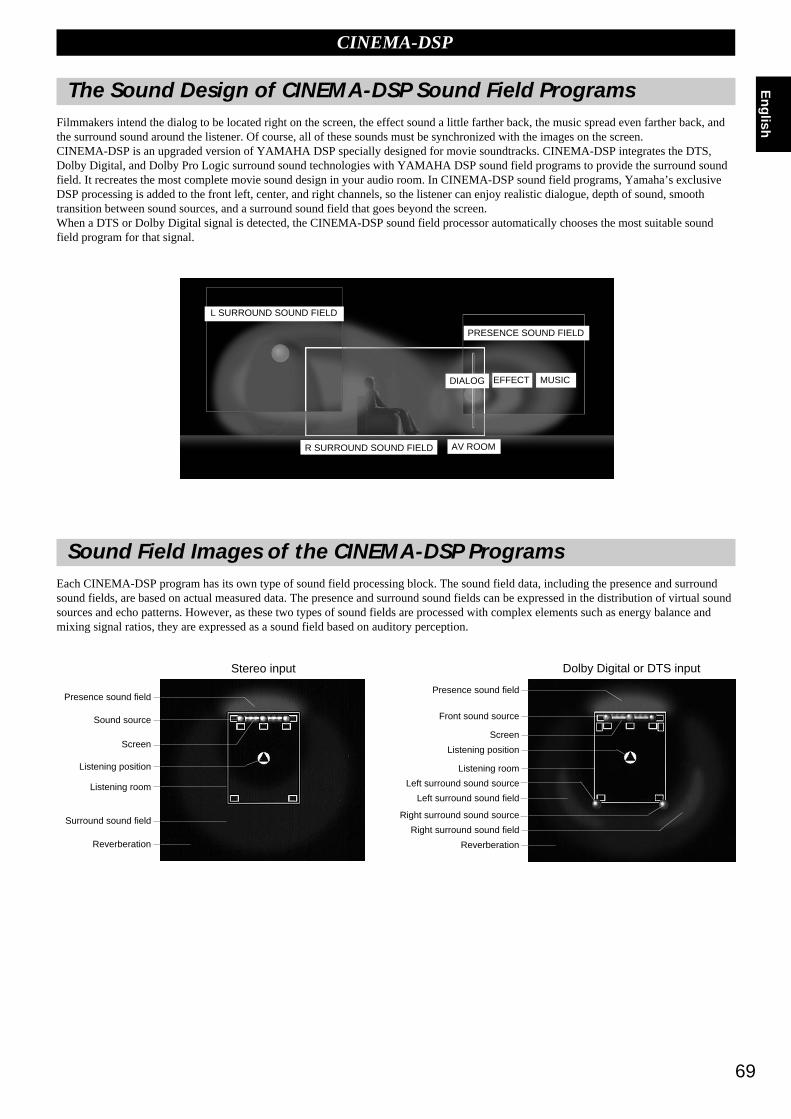
69
English
CINEMA-DSP
The Sound Design of CINEMA-DSP Sound Field ProgramsFilmmakers intend the dialog to be located right on the screen, the effect sound a little farther back, the music spread even farther back, andthe surround sound around the listener. Of course, all of these sounds must be synchronized with the images on the screen.CINEMA-DSP is an upgraded version of YAMAHA DSP specially designed for movie soundtracks. CINEMA-DSP integrates the DTS,Dolby Digital, and Dolby Pro Logic surround sound technologies with YAMAHA DSP sound field programs to provide the surround soundfield. It recreates the most complete movie sound design in your audio room. In CINEMA-DSP sound field programs, Yamaha’s exclusiveDSP processing is added to the front left, center, and right channels, so the listener can enjoy realistic dialogue, depth of sound, smoothtransition between sound sources, and a surround sound field that goes beyond the screen.When a DTS or Dolby Digital signal is detected, the CINEMA-DSP sound field processor automatically chooses the most suitable soundfield program for that signal.
Sound Field Images of the CINEMA-DSP ProgramsEach CINEMA-DSP program has its own type of sound field processing block. The sound field data, including the presence and surroundsound fields, are based on actual measured data. The presence and surround sound fields can be expressed in the distribution of virtual soundsources and echo patterns. However, as these two types of sound fields are processed with complex elements such as energy balance andmixing signal ratios, they are expressed as a sound field based on auditory perception.
Stereo input
Presence sound field
Sound source
Screen
Listening position
Listening room
Surround sound field
Reverberation
Dolby Digital or DTS input
Presence sound field
Front sound source
Screen
Listening position
Listening room
Left surround sound source
Left surround sound field
Right surround sound source
Right surround sound field
Reverberation
L SURROUND SOUND FIELD
PRESENCE SOUND FIELD
R SURROUND SOUND FIELD AV ROOM
DIALOG EFFECT MUSIC

70
Ad
dit
ion
al
Info
rmati
on
CINEMA-DSP
Movie Theater ProgramsMost movie software has four-channel (left, center, right and surround) sound information encoded using Dolby Surround matrix processingand stored on the left and right tracks. These signals are processed by the Dolby Pro Logic decoder. The Movie Theater Programs aredesigned to recreate the spaciousness and delicate nuances of sound that tend to be lost in the encoding and decoding processes.The six-channel soundtracks found on 70 mm film produce precise sound field localization and rich, deep sound without using matrixprocessing. The DSP-AX1’s Movie Theater 70 mm Programs provide the same quality of sound and sound localization that six-channelsoundtracks do. The built-in Dolby Digital decoder brings the professional quality sound designed for movie theaters, into your home. Withthe DSP-AX1’s Movie Theater program, you can recreate a dynamic sound that gives you the feeling of being at a public theater in yourliving room using the Dolby Digital technology.
Dolby Pro Logic + DSP Sound Field EffectThese programs express an immense sound field and a large surround effect. They also give depth to the sound from the Main Speakersto recreate the realistic sound of a Dolby Stereo theater.
Dolby Digital/DTS + DSP Sound Field EffectThese programs use Yamaha’s tri-field DSP process on each of the Dolby Digital signals for the front, left surround, and right surroundchannels. This processing enables the DSP-AX1 to reproduce the immense sound field and surround expression of a Dolby Digitalequipped movie theater without sacrificing the clear separation of all channels.
Dolby Digital/Matrix 6.1+ DSP Sound Field Effect or DTS ES+ DSP Sound Field EffectThese programs provide the full experience of spacious surround effects with the addition of an extra Rear Center DSP sound fieldcreated using the Rear Center channel.
Presence DSPSound Field
Right Surround DSPSound Field
Left Surround DSPSound Field
Presence DSPSound Field
Surround DSPSound Field

71
English
CINEMA-DSP Sound Field Program
According to the input signal format, the DSP-AX1 automatically chooses the appropriate decoder and DSP sound field pattern.
ProgramGroup
7
8
9
10
11
12
CONCERTVIDEO 1
CONCERTVIDEO 2
TVTHEATER
MOVIETHEATER 1
MOVIETHEATER 2
PRO LOGIC
DOLBYDIGITAL
DTSDIGITAL SUR
Pop/Rock
DJ
Classical/Opera
Pavilion
Mono Movie
Variety/Sports
70 mm Spectacle
70 mm Sci-Fi
70 mm Adventure
70 mm General
Normal
Enhanced
InputStereo(2ch)
DOLBY DIGITAL(5.1ch)
DTS Spectacle
DTS Sci-Fi
DTS Adventure
DTS General
Normal
Enhanced
DTS(5.1ch)
DOLBY DIGITAL(6.1ch)*
DTS ES(6.1ch)*
Table of Program Names for Each Input Format
* The Matrix decoder is ON.
Program Groups 7~9
These are sound field programs for the audio-video sources.
Program Groups 10~12
Ideal for reproducing a movie program which is encoded with Dolby Surround, Dolby Digital, or DTS. When the newest movieprogram encoded with Dolby Digital Surround EX or DTS ES is input, you can enjoy the full 6.1 channel reproduction using theinternal Matrix decoder.
PRO LOGIC functions when the input signal is analog or PCM audio, or encoded with Dolby Digital in two channels.
DOLBY DIGITAL functions when the input signal is encoded with Dolby Digital in more than two channels.
DTS DIGITAL SUR functions when the input signal is encoded with DTS.
Note:
• No sound wil be output from the Main speakers when a monaural source is played with sound field Program Groups 7~12.
Spectacle ES
Sci-Fi ES
Adventure ES
General ES
ES
Enhanced ES
– – – – – – – –
– – – – – – – –
– – – – – – – –
– – – – – – – –
– – – – – – – –
– – – – – – – –
– – – – – – – –
– – – – – – – –
– – – – – – – –
– – – – – – – –
– – – – – – – –
– – – – – – – –
– – – – – – – –
– – – – – – – –
– – – – – – – –
– – – – – – – –
– – – – – – – –
– – – – – – – –
– – – – – – – –
– – – – – – – –
– – – – – – – –
– – – – – – – –
– – – – – – – –
– – – – – – – –
– – – – – – – –
– – – – – – – –
– – – – – – – –
– – – – – – – –
– – – – – – – –
– – – – – – – –
– – – – – – – –
– – – – – – – –
– – – – – – – –
– – – – – – – –
– – – – – – – –
– – – – – – – –
– – – – – – – –
– – – – – – – –
– – – – – – – –
– – – – – – – –
Spectacle 6.1
Sci-Fi 6.1
Adventure 6.1
General 6.1
Matrix 6.1
Enhanced 6.1
– – – – – – – –
– – – – – – – –
– – – – – – – –
– – – – – – – –
DGTL Spectacle
DGTL Sci-Fi
DGTL Adventure
DGTL General
Normal
Enhanced
72
Ad
dit
ion
al
Info
rmati
on
CINEMA-DSP Sound Field Program
Program Group 9 : TV Theater Mono Movie
This program is provided for reproducing monaural videosources (such as old movies). The program produces theoptimum reverberation to create sound depth using only thepresence sound field.
Variety/SportsThough the presence sound field is relatively narrow, thesurround sound field employs the sound environment of a largeconcert hall. With this program, you can enjoy watching variousTV programs such as news, variety shows, music programs orsports programs.
Program Group 10 : Movie Theater 1 Spectacle
This program creates the extremely wide sound field of a 70 mmmovie theater. It precisely reproduces the source sound in detail,making both the video and the sound fields incredibly real. Thisprogram is ideal for any kind of Dolby Surround video source(especially large-scale movie productions).
Sci-FiThis program clearly reproduces the broad and expansivecinematic space from the soundtracks of the latest science fictionfilms.
Program Group 11 : Movie Theater 2 Adventure
This program is ideal for precisely reproducing the sound designof the newest 70 mm and multichannel soundtrack films. Thesound field is made to be similar to that of the newest movietheaters, so the reverberations of the sound field itself arerestrained as much as possible.
GeneralThis program is for reproducing sounds from 70 mm andmultichannel soundtrack films, and is characterized by a soft andextensive sound field. The presence sound field is relativelynarrow. It spatially spreads all around and toward the screen,restraining the effect of conversations without losing clarity.
Program Group 12 : Dolby/DTS Surround Normal/Matrix 6.1/ES
The built-in decoder precisely reproduces sounds and soundeffects from sources. The highly efficient decoding processimproves crosstalk and channel separation and makes soundpositioning smoother and more precise.
In this program, no DSP effect is applied.
Enhanced/6.1/ESThis program ideally simulates the multiple surround speakersystems of 35 mm film theaters. The Dolby Surround decodingand the digital sound field processing create precise effectswithout altering the original sound orientation. The surroundeffects produced by this sound field wrap around the viewernaturally from the back to the left and right and toward thescreen.
Program Group 7 : Concert Video 1
Pop/RockThis program produces an enthusiastic atmosphere and lets youfeel as if you are at an actual jazz or rock concert.
DJThe sound field makes the voice of a disc jockey sound clearer.
Program Group 8 : Concert Video 2 Classical/Opera
This program provides excellent vocal depth and overall clarityby restraining excessive reverberation.
The surround sound field is relatively moderate but it reproducesbeautiful sound using data collected from a concert hall.
PavilionThis program reproduces vocals clearly, letting you feel thespaciousness of a pavilion. Reverberation, which is somewhatdelayed, reproduces the live acoustics unique to a pavilion, andhelps to make concert scenes more exciting.

73
English
You can enjoy good quality sound with the preset parameters. Although you do not have to change the initial settings, you can change someof the parameters to better suit the input source or your listening room.
Changing Parameter Settings
11 Set PARAMETER/SET MENU to PARAMETER on the remotecontrol.
22 Turn on your video monitor and press ON SCREEN to select thefull display.
33 Select the sound field program you want to adjust.
44 Press % or % to select the parameter.
55 Press + or – to change the parameter value.
When you set the parameter to a value other than the factory preset value, anasterisk mark appears by the parameter name on the monitor screen.
66 Repeat steps 3 through 5 above as necessary to change otherprogram parameters.
Sound Field Program Parameter Editing
Program No. Program Name
Program Type (subprogram)
Cursor Parameters
Example of the CONCERT HALL 1
Resetting a Parameter to the Factory Preset Value
To reset all of the parameters back to thefactory preset valuesUse the SET MENU to reset all of the parameter values of allDSP programs within the selected group to the factory presetvalues (see page 47). This operation resets all of the parametervalues of all DSP programs within that group to the factorypreset values.
To reset some of the parameters to thefactory preset valuesSelect the parameter you want to reset. Then, press and hold + or– until the value stops at the factory preset value temporarily.(The asterisk mark by the parameter name disappears on thevideo monitor.)
Notes:
• The available parameters may be displayed on more than one OSD page for some of the programs. To scroll through pages, press % or %.
• When “MEMORY GUARD!” appears on the screen, the Memory Guard function is on, and you cannot change parameter values. Turn off the MemoryGuard function using the SET MENU (see page 48).
PARAMETER
SET MENU
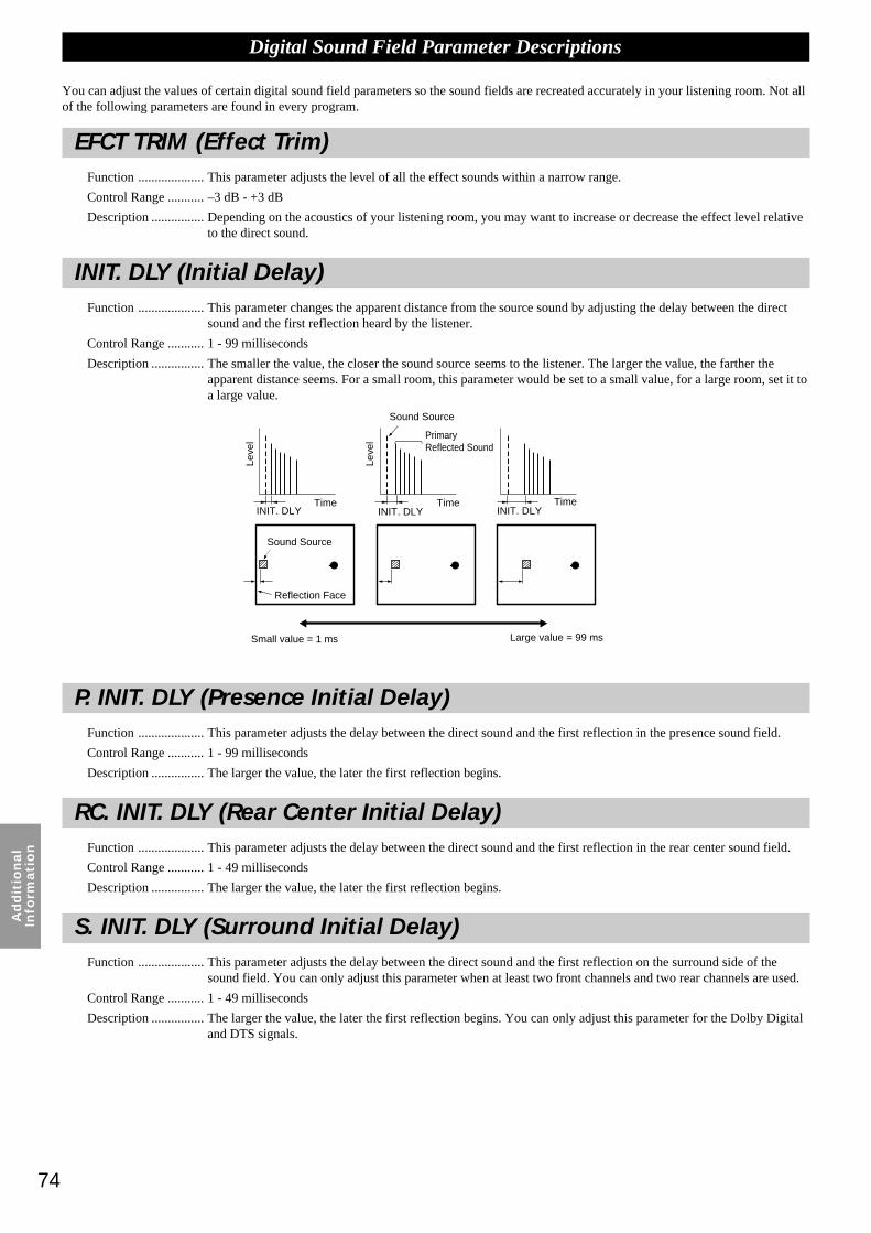
74
Ad
dit
ion
al
Info
rmati
on
Digital Sound Field Parameter Descriptions
You can adjust the values of certain digital sound field parameters so the sound fields are recreated accurately in your listening room. Not allof the following parameters are found in every program.
EFCT TRIM (Effect Trim)Function .................... This parameter adjusts the level of all the effect sounds within a narrow range.
Control Range ........... –3 dB - +3 dB
Description ................ Depending on the acoustics of your listening room, you may want to increase or decrease the effect level relativeto the direct sound.
INIT. DLY (Initial Delay)Function .................... This parameter changes the apparent distance from the source sound by adjusting the delay between the direct
sound and the first reflection heard by the listener.
Control Range ........... 1 - 99 milliseconds
Description ................ The smaller the value, the closer the sound source seems to the listener. The larger the value, the farther theapparent distance seems. For a small room, this parameter would be set to a small value, for a large room, set it toa large value.
INIT. DLY INIT. DLY INIT. DLY
Sound Source
Sound Source
Reflection Face
Small value = 1 ms Large value = 99 ms
PrimaryReflected Sound
Leve
l
Leve
l
Time Time Time
P. INIT. DLY (Presence Initial Delay)Function .................... This parameter adjusts the delay between the direct sound and the first reflection in the presence sound field.
Control Range ........... 1 - 99 milliseconds
Description ................ The larger the value, the later the first reflection begins.
RC. INIT. DLY (Rear Center Initial Delay)Function .................... This parameter adjusts the delay between the direct sound and the first reflection in the rear center sound field.
Control Range ........... 1 - 49 milliseconds
Description ................ The larger the value, the later the first reflection begins.
S. INIT. DLY (Surround Initial Delay)Function .................... This parameter adjusts the delay between the direct sound and the first reflection on the surround side of the
sound field. You can only adjust this parameter when at least two front channels and two rear channels are used.
Control Range ........... 1 - 49 milliseconds
Description ................ The larger the value, the later the first reflection begins. You can only adjust this parameter for the Dolby Digitaland DTS signals.
INIT. DLYINIT. DLYINIT. DLY
Reflection Face
Sound Source
Small value = 1 ms Large value = 99 ms
Sound Source
PrimaryReflected Sound

75
English
Digital Sound Field Parameter Descriptions
S. DELAY S. INIT. DELAY
SURROUND (LS/RS)
S. DELAY
Leve
l
Time
S Sound Field
Direct Sound
Dolby Digital or DTS Input
Leve
l
Time
S Sound Field
Direct Sound
OthersThe surround sound field is not reproduced.
Time
Leve
l
Time
Leve
l
Leve
l
Time
Sound Source
PrimaryReflectedSound
Smallvalue
Large value
Small value = 0.1 Large value = 2.0
Sound Source
S. DLY (Surround Delay)Function .................... This parameter adjusts the delay between the direct sound and the first reflection in the surround sound field.
Control Range ........... 0 - 49 milliseconds (The range depends on the signal format.)
Description ................ When Dolby Digital signals are decoded: the larger the parameter, the later the surround sound source begins.When a non-Dolby Digital program is decoded: the larger the parameter, the later the surround sound fieldbegins.No surround sound source is produced.
ROOM SIZEFunction .................... This parameter adjusts the apparent size of the surround sound field. The larger the value, the larger the surround
sound field becomes.
Control Range ........... 0.1 - 2.0
Description ................ As the sound is repeatedly reflected around a room, the larger the hall is, the longer the time between the originalreflected sound and the subsequent reflections. By controlling the time between the reflected sounds, you canchange the apparent size of the virtual venue. Changing this parameter from one to two, doubles the apparentlength of the room.
S. DELAY S. INIT.DELAY
S. DELAY
SURROUND (LS/RS)

76
Ad
dit
ion
al
Info
rmati
on
Digital Sound Field Parameter Descriptions
RC. ROOM SIZE (Rear Center Room Size)Function .................... This parameter adjusts the apparent size of the rear center sound field.
Control Range ........... 0.1 - 2.0
Description ................ The larger the value, the more reflective the presence sound field walls become.
S. ROOM SIZE (Surround Room Size)Function .................... This parameter adjusts the apparent size of the surround sound field.
Control Range ........... 0.1 - 2.0
Description ................ The larger the value, the larger the surround sound field becomes.
LIVENESSFunction .................... This parameter adjusts the reflectivity of the virtual walls in the hall by changing the rate at which the early
reflections decay.
Control Range ........... 0 - 10
Description ................ The early reflections of a sound source decay much faster in a room with acoustically absorbent wall surfacesthan in one which has highly reflective surfaces. A room with acoustically absorbent surfaces is referred to as“dead,” while a room with highly reflective surfaces is referred to as “live.” The LIVENESS parameter lets youadjust the early reflection decay rate, and thus the “liveness” of the room.
Leve
l
Time
Source Sound
Leve
l
Time
Leve
l
Time
Dead
Live
Source Sound
Small ReflectedSound
LargeReflected Sound
Small value = 0 Large value = 10
S. LIVENESS (Surround Liveness)Function .................... This parameter adjusts the apparent reflectivity of the virtual walls in the surround sound field.
Control Range ........... 0 - 10
Description ................ The larger the value, the more reflective the surround sound field walls become.
RC. LIVENESS (Rear Center Liveness)Function .................... This parameter adjusts the apparent reflectivity of the virtual wall in the rear center sound field.
Control Range ........... 0 - 10
Description ................ The larger the value, the more reflective the surround sound field walls become.

77
English
Digital Sound Field Parameter Descriptions
REV. TIME (Reverberation Time)Function .................... This parameter adjusts the amount of time it takes for the dense, subsequent reverberation sound to decay by 60
dB (at 1 kHz). This changes the apparent size of the acoustic environment over an extremely wide range.
Control Range ........... 1.0 - 5.0 seconds
Description ................ Set a longer reverberation time for “dead” sources and listening room environments and a shorter time for “live”sources and listening room environments.
REV. DELAY (Reverberation Delay)Function .................... This parameter adjusts the time difference between the beginning of the direct sound and the beginning of the
reverberation sound.
Control Range ........... 0 - 250 milliseconds
Description ................ The larger the value, the later the reverberation sound begins. A later reverberation sound makes you feel like youare in a larger acoustic environment.
60 dB 60 dB 60 dB
Reverberation
ShortReverberation
Long Reverberation
Rever-beration
Small value = 1.0 s Large value = 5.0 s
REV. LEVEL (Reverberation Level)Function .................... This parameter adjusts the volume of the reverberation sound.
Control Range ........... 0 - 100%
Description ................ The larger the value, the stronger the reverberation becomes.
(dB)
60dB
Leve
l
Time
Source Sound
Reverberation
Leve
l
Time
Source Sound
REV. TIME REV. TIMEREV. TIME
REV.DELAY
REV TIME
REV LEVEL
Primary Reflected SoundSource Sound
Source Sound
Reverberation

78
Ap
pen
dix
Appendix
Troubleshooting 79
Reference Chart for the INPUT and OUTPUT Jacks 82
CINEMA - EQ Frequency Characteristics 82
Specifications 83
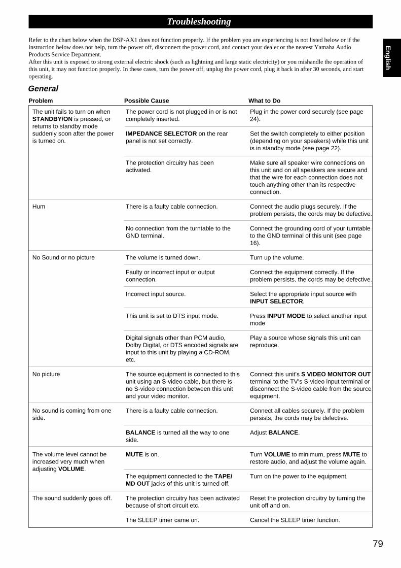
79
English
The unit fails to turn on whenSTANDBY/ON is pressed, orreturns to standby modesuddenly soon after the poweris turned on.
Hum
No Sound or no picture
No picture
No sound is coming from oneside.
The volume level cannot beincreased very much whenadjusting VOLUME.
The sound suddenly goes off.
Plug in the power cord securely (see page24).
Set the switch completely to either position(depending on your speakers) while this unitis in standby mode (see page 22).
Make sure all speaker wire connections onthis unit and on all speakers are secure andthat the wire for each connection does nottouch anything other than its respectiveconnection.
Connect the audio plugs securely. If theproblem persists, the cords may be defective.
Connect the grounding cord of your turntableto the GND terminal of this unit (see page16).
Turn up the volume.
Connect the equipment correctly. If theproblem persists, the cords may be defective.
Select the appropriate input source withINPUT SELECTOR.
Press INPUT MODE to select another inputmode
Play a source whose signals this unit canreproduce.
Connect this unit’s S VIDEO MONITOR OUTterminal to the TV’s S-video input terminal ordisconnect the S-video cable from the sourceequipment.
Connect all cables securely. If the problempersists, the cords may be defective.
Adjust BALANCE .
Turn VOLUME to minimum, press MUTE torestore audio, and adjust the volume again.
Turn on the power to the equipment.
Reset the protection circuitry by turning theunit off and on.
Cancel the SLEEP timer function.
The power cord is not plugged in or is notcompletely inserted.
IMPEDANCE SELECTOR on the rearpanel is not set correctly.
The protection circuitry has beenactivated.
There is a faulty cable connection.
No connection from the turntable to theGND terminal.
The volume is turned down.
Faulty or incorrect input or outputconnection.
Incorrect input source.
This unit is set to DTS input mode.
Digital signals other than PCM audio,Dolby Digital, or DTS encoded signals areinput to this unit by playing a CD-ROM,etc.
The source equipment is connected to thisunit using an S-video cable, but there isno S-video connection between this unitand your video monitor.
There is a faulty cable connection.
BALANCE is turned all the way to oneside.
MUTE is on.
The equipment connected to the TAPE/MD OUT jacks of this unit is turned off.
The protection circuitry has been activatedbecause of short circuit etc.
The SLEEP timer came on.
Troubleshooting
Refer to the chart below when the DSP-AX1 does not function properly. If the problem you are experiencing is not listed below or if theinstruction below does not help, turn the power off, disconnect the power cord, and contact your dealer or the nearest Yamaha AudioProducts Service Department.After this unit is exposed to strong external electric shock (such as lightning and large static electricity) or you mishandle the operation ofthis unit, it may not function properly. In these cases, turn the power off, unplug the power cord, plug it back in after 30 seconds, and startoperating.
Problem Possible Cause What to Do
General
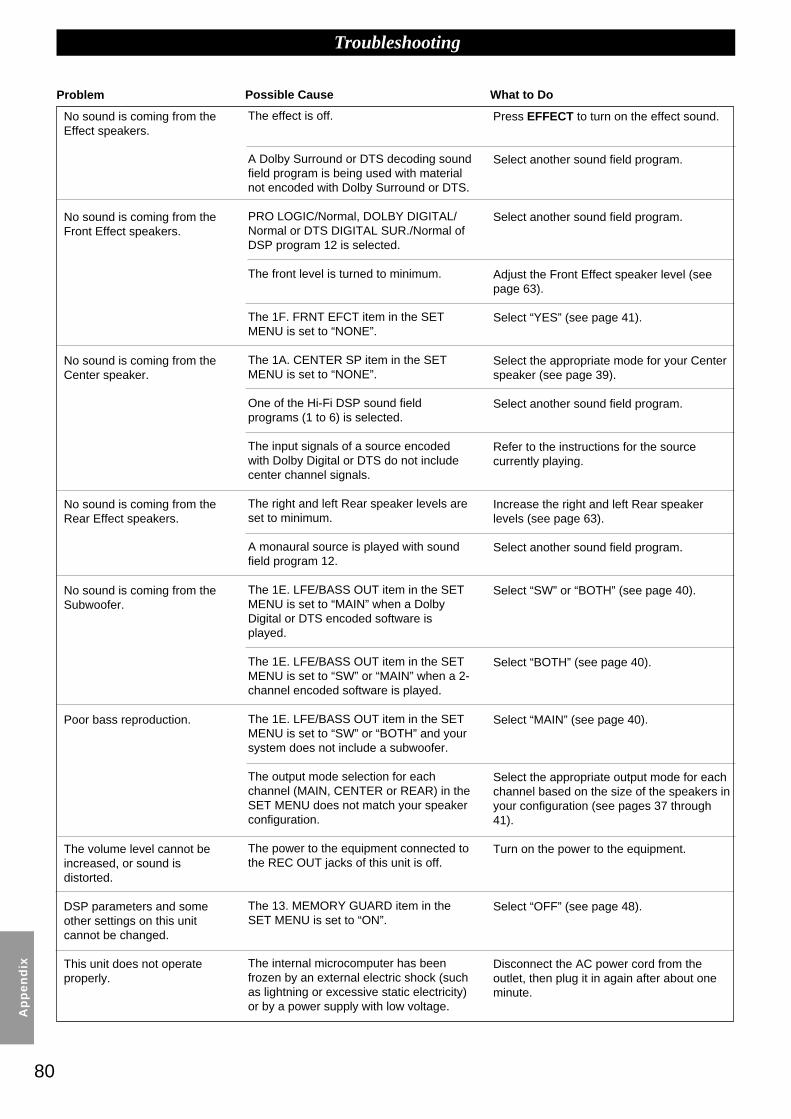
80
Ap
pen
dix
Troubleshooting
No sound is coming from theEffect speakers.
No sound is coming from theFront Effect speakers.
No sound is coming from theCenter speaker.
No sound is coming from theRear Effect speakers.
No sound is coming from theSubwoofer.
Poor bass reproduction.
The volume level cannot beincreased, or sound isdistorted.
DSP parameters and someother settings on this unitcannot be changed.
This unit does not operateproperly.
Press EFFECT to turn on the effect sound.
Select another sound field program.
Select another sound field program.
Adjust the Front Effect speaker level (seepage 63).
Select “YES” (see page 41).
Select the appropriate mode for your Centerspeaker (see page 39).
Select another sound field program.
Refer to the instructions for the sourcecurrently playing.
Increase the right and left Rear speakerlevels (see page 63).
Select another sound field program.
Select “SW” or “BOTH” (see page 40).
Select “BOTH” (see page 40).
Select “MAIN” (see page 40).
Select the appropriate output mode for eachchannel based on the size of the speakers inyour configuration (see pages 37 through41).
Turn on the power to the equipment.
Select “OFF” (see page 48).
Disconnect the AC power cord from theoutlet, then plug it in again after about oneminute.
The effect is off.
A Dolby Surround or DTS decoding soundfield program is being used with materialnot encoded with Dolby Surround or DTS.
PRO LOGIC/Normal, DOLBY DIGITAL/Normal or DTS DIGITAL SUR./Normal ofDSP program 12 is selected.
The front level is turned to minimum.
The 1F. FRNT EFCT item in the SETMENU is set to “NONE”.
The 1A. CENTER SP item in the SETMENU is set to “NONE”.
One of the Hi-Fi DSP sound fieldprograms (1 to 6) is selected.
The input signals of a source encodedwith Dolby Digital or DTS do not includecenter channel signals.
The right and left Rear speaker levels areset to minimum.
A monaural source is played with soundfield program 12.
The 1E. LFE/BASS OUT item in the SETMENU is set to “MAIN” when a DolbyDigital or DTS encoded software isplayed.
The 1E. LFE/BASS OUT item in the SETMENU is set to “SW” or “MAIN” when a 2-channel encoded software is played.
The 1E. LFE/BASS OUT item in the SETMENU is set to “SW” or “BOTH” and yoursystem does not include a subwoofer.
The output mode selection for eachchannel (MAIN, CENTER or REAR) in theSET MENU does not match your speakerconfiguration.
The power to the equipment connected tothe REC OUT jacks of this unit is off.
The 13. MEMORY GUARD item in theSET MENU is set to “ON”.
The internal microcomputer has beenfrozen by an external electric shock (suchas lightning or excessive static electricity)or by a power supply with low voltage.
Problem Possible Cause What to Do

81
EnglishA source cannot be recorded
by a tape deck or VCRconnected to this unit.
“CHECK SP WIRES!" appearson the display.
There is noise from a nearbyTV or tuner.
The sound is degraded whenlistening with the headphonesconnected to the CD player orcassette deck that areconnected to this unit.
“INPUT DATA ERROR”appears on the display and nosound is heard.
Make additional connections to the analogjacks (see pages 16 through 19).
Make sure all speaker cables areconnected correctly.
Move this unit farther away from the affectedequipment.
Turn on the power to this unit.
Check the source, or turn off the sourceequipment, then turn it on again.
The source unit is connected to this unitusing digital jacks only.
Speaker cables are short circuited.
This unit is too close to the affectedequipment.
The power to this unit is off.
A non-standard source is played back, orthe equipment playing back the source isnot operating correctly.
Problem Possible Cause What to Do
The remote control does notwork.
The remote control does notfunction properly.
The remote controldoes not “learn” new functions.(The TRANSMIT indicator doesnot light up or flash.)
Continuous functions such asvolume are learned, butoperate only for a momentbefore stopping.
Replace the batteries with new ones andpress RESET (see page 5).
Press RESET on the remote control (seepage 5).
The remote control will function within amaximum range of 6 m (20 feet), no morethan 30 degrees off-axis from the front panel(see page 5).
Change the position of this unit.
Press RESET on the remote control (seepage 5).
Replace the batteries (and press RESET onthe remote control) (see page 5).
Place the remote controls at the properdistance (see page 58).
Learning is not possible.
Further learning is not possible without deletingunnecessary new functions (see page 62).
Press RESET on the remote control (seepage 5).
Be sure to press and hold the function buttonon the other remote control until TRANSMITbegins flashing slowly.
The batteries are dead.
The internal microcomputer has “frozen”.
Wrong distance or angle.
Direct sunlight or lighting (such as aninverter type of fluorescent lamp) is strikingthe remote control sensor of this unit.
The internal microcomputer has “frozen”.
The batteries of this remote control and/orthe other remote control are too weak.
The distance between the two remotecontrols is too far or near.
The signal coding or modulation of theother remote control is not compatible withthis remote control.
Memory capacity is full.
The internal microcomputer has “frozen”.
The learning process is incomplete.
Problem Possible Cause What to Do
Remote Control
Troubleshooting

82
Ap
pen
dix
Reference Chart for the INPUT and OUTPUT Jacks
CINEMA - EQ Frequency Characteristics
Cinema EQ is a digital equalizer that lets you independently adjust the sound quality of each speaker.
ΟΟΟΟΟΟΟΟΟΟΟΟ
ΟΟ
Ο
Ο ∗3
Ο
Ο ∗4
Ο
Ο
ΟRF
Ο
Ο
ΟΟΟΟΟΟ ∗2
ΟΟΟΟΟΟ
Ο
ΟΟ Ο
ΟΟΟΟΟΟ
Ο
Ο Ο
Ο ∗1
Ο ∗1
Ο ∗1
Ο
Ο
*1 This input can be changed to another video input by using the SET MENU. *2 Only for VCR 1*3 SPLIT L,R, and MONO outputs *4 MAIN L,R, CENTER, FRONT L,R, REAR L,R, and REAR CENTER total 8 channels
HIGH FrequencyRange GAIN +6 ~ –9 dB
GAIN
FRQ
PEQ FrequencyRange GAIN +6 ~ –9 dB Q 1.85 (fixed)
+6
+3
0
–3
–6
–9
20 50 100 200 500 1k 2k 5k 10k 20k
GAIN
FRQ
HIGH FrequencyRange FRQ 1.0 ~ 12.7 kHz
+6
+3
0
–3
–6
–9
20 50 100 200 500 1k 2k 5k 10k 20k
1.0k 1.2k 1.6k 2.0k 2.5k 3.2k 4.0k 5.0k 5.7k 6.3k 7.1k 8.0k 9.0k10.1k11.3k12.7kHz
GAIN
FRQ
PEQ FrequencyRange FRQ 1.0 ~ 12.7 kHz Q 1.85 (fixed)
+6
+3
0
–3
–6
–9
20 50 100 200 500 1k 2k 5k 10k 20k
1.0k 1.2k 1.6k 2.0k 2.5k 3.2k 4.0k 5.0k 5.7k 6.3k 7.1k 8.0k 9.0k10.1k11.3k12.7kHz
GAIN
FRQ
+6
+3
0
–3
–6
–9
20 50 100 200 500 1k 2k 5k 10k 20k
G
HIGH (High Shelving Filter): Adjusts highfrequency response smoothly. There are 16responses affecting frequencies in the 1 to 12.7kHz range, while gain is adjusted between +6 and–9 dB.
PEQ (Parametric Equalizer): Allowssmooth boost and cut at an arbitrary frequencyrange. The center frequency can be in the 1 to12.7 kHz range, with gain between +6 and –9 dB.
PHONOCDTUNERTAPEMDDVDLDD-TVCBL/SATVCR 1, 2, 3V-AUX6 CH INPUTSUBWOOFERZONE 2 OUTMONITOR OUTSPEAKER OUTHEADPHONES
ANALOG
AUDIO
IN OUT
DIGITAL
COAXIAL OPTICAL
IN OUT IN OUT
VIDEO
COMPOSITE S-VIDEO COMPONENT
SIGNAL
IN OUT IN OUT IN OUT
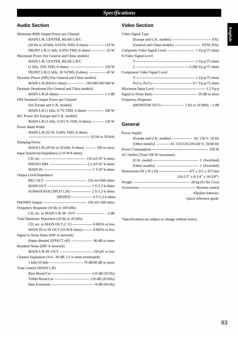
83
English
Specifications
Audio Section
Minimum RMS Output Power per Channel
MAIN L/R, CENTER, REAR L/R/C
(20 Hz to 20 kHz, 0.015% THD, 8 ohms) ------------ 110 W
FRONT L/R (1 kHz, 0.05% THD, 8 ohms) ------------ 35 W
Maximum Power [for General and China models]
MAIN L/R, CENTER, REAR L/R/C
(1 kHz, 10% THD, 8 ohms) ---------------------------- 150 W
FRONT L/R (1 kHz, 10 %THD, 8 ohms) -------------- 45 W
Dynamic Power (IHF) [for General and China models]
MAIN L/R (8/6/4/2 ohms) -------------- 150/180/240/340 W
Dynamic Headroom [for General and China models]
MAIN L/R (8 ohms) --------------------------------------1.3 dB
DIN Standard Output Power per Channel
[for Europe and U.K. models]
MAIN L/R (1 kHz, 0.7% THD, 4 ohms) ------------- 180 W
IEC Power [for Europe and U.K. models]
MAIN L/R (1 kHz, 0.015 % THD, 8 ohms) ---------- 120 W
Power Band Width
MAIN L/R (55 W, 0.04% THD, 8 ohms)--------------------------------------------------- 10 Hz to 50 kHz
Damping Factor
MAIN L/R (20 Hz to 20 kHz, 8 ohms) --------- 200 or more
Input Sensitivity/Impedance (110 W/8 ohms)
CD, etc. ------------------------------------- 150 mV/47 k-ohms
PHONO MM ------------------------------- 2.5 mV/47 k-ohms
MAIN IN -----------------------------------------1 V/47 k-ohms
Output Level/Impedance
REC OUT ----------------------------------- 150 mV/600 ohms
MAIN OUT ------------------------------------- 1 V/1.2 k-ohms
SUBWOOFER [SPLIT L/R] ----------------- 2 V/1.2 k-ohms
[MONO] ------------------ 4 V/1.2 k-ohms
PHONES Output ------------------------------------ 150 mV/100 ohms
Frequency Response (10 Hz to 100 kHz)
CD, etc. to MAIN L/R SP. OUT ------------------------ –3 dB
Total Harmonic Distortion (20 Hz to 20 kHz)
CD, etc. to MAIN OUT (1 V) ----------------- 0.005% or less
MAIN IN to SP OUT (55 W/8 ohms) -------- 0.005% or less
Signal to Noise Ratio (IHF-A network)
(Input shorted, EFFECT off) ------------------ 96 dB or more
Residual Noise (IHF-A network)
MAIN L/R SP. OUT --------------------------- 150 µV or less
Channel Separation (Vol –30 dB, 5.1 k-ohms terminated)
1 kHz/10 kHz ---------------------------- 70 dB/60 dB or more
Tone Control (MAIN L/R)
Bass Boost/Cut --------------------------------- ±10 dB (50 Hz)
Treble Boost/Cut ----------------------------- ±10 dB (20 kHz)
Bass Extension ---------------------------------- +6 dB (60 Hz)
Video Section
Video Signal Type
[Europe and U.K. models] --------------------------------- PAL
[General and China models] ---------------------- NTSC/PAL
Composite Video Signal Level ----------------------- 1 Vp-p/75 ohms
S-Video Signal Level
Y ------------------------------------------------- 1 Vp-p/75 ohms
C -------------------------------------------- 0.286 Vp-p/75 ohms
Component Video Signal Level
Y ------------------------------------------------- 1 Vp-p/75 ohms
PB/CB, PR/CR --------------------------------- 0.7 Vp-p/75 ohms
Maximum Input Level ------------------------------------------ 1.5 Vp-p
Signal to Noise Ratio ------------------------------------ 50 dB or more
Frequency Response
(MONITOR OUT) ------------------- 5 Hz to 10 MHz, –3 dB
General
Power Supply
[Europe and U.K. models] ----------------- AC 230 V, 50 Hz
[Other models] -----------AC 110/120/220/240 V, 50/60 Hz
Power Consumption----------------------------------------------- 550 W
AC Outlets (Total 100 W maximum)
[U.K. model] -------------------------------------- 1 (Switched)
[Other models] ----------------------------------- 3 (Switched)
Dimensions (W x H x D) ------------------------- 471 x 211 x 473 mm
(18-1/2” x 8-1/4” x 18-5/8”)
Weight ----------------------------------------------- 28 kg (61 lbs 11oz)
Accessories ----------------------------------------------- Remote control
Alkaline batteries
Quick reference guide
*Specifications are subject to change without notice.

V482940-1Printed in Japan
YAMAHA ELECTRONICS CORPORATION, USA 6660 ORANGETHORPE AVE., BUENA PARK, CALIF. 90620, U.S.A.YAMAHA CANADA MUSIC LTD. 135 MILNER AVE., SCARBOROUGH, ONTARIO M1S 3R1, CANADAYAMAHA ELECTRONIK EUROPA G.m.b.H. SIEMENSSTR. 22-34, 25462 RELLINGEN BEI HAMBURG, F.R. OF GERMANYYAMAHA ELECTRONIQUE FRANCE S.A. RUE AMBROISE CROIZAT BP70 CROISSY-BEAUBOURG 77312 MARNE-LA-VALLEE CEDEX02, FRANCEYAMAHA ELECTRONICS (UK) LTD. YAMAHA HOUSE, 200 RICKMANSWORTH ROAD WATFORD, HERTS WD1 7JS, ENGLANDYAMAHA SCANDINAVIA A.B. J A WETTERGRENS GATA 1, BOX 30053, 400 43 VÄSTRA FRÖLUNDA, SWEDENYAMAHA MUSIC AUSTRALIA PTY, LTD. 17-33 MARKET ST., SOUTH MELBOURNE, 3205 VIC., AUSTRALIA

SYSTEMPOWER STANDBY V-AUX TAPE PHONO
D-TV CBL/SAT TUNER MD CD
VCR 1 VCR 2 VCR 3 LD DVD
6CH INPUT
TITLE
ENTER
MENU SOUNDDISPLAY
SOURCE
SELECT SEARCH CHAPTER
%
! !$
* #
$
%
%
%%
%
10KEY DSP HALL 1 HALL 2 CHURCH JAZZ CLUB
ROCKCONCERT
ENTER-TAINMENT
CONCERTVIDEO 2
CONCERTVIDEO 1
POWER REC STOP PAUSE PLAY
6.1/ESTV
THEATERMOVIE
THEATER 2MOVIE
THEATER 1
0 +10 +100
1 2 3 4
5 6 7 8
9 10 11 12
+ + +TV VOL
A / B / C / D / E PRESET
TV INPUT
TV MUTE
CH
DISC
MUTE
EFFECT
VOLUME
+–
/
CHP/INDEX
– – –
FAST FORWARD
REC / PAUSE
REWIND
DECK A / DECK B
DIRECTION A/BPLAYSTOP
ON SCREEN LEVEL
SLEEP TEST
PARAMETER
SET MENU%
%
TRANSMIT RE-NAME CLEARMACRO
MACROLEARN OFF ON
SYSTEMPOWER STANDBY V-AUX TAPE PHONO
D-TV CBL/SAT TUNER MD CD
VCR 1 VCR 2 VCR 3 LD DVD
6CH INPUT
TITLE
ENTER
MENU SOUNDDISPLAY
SOURCE
SELECT SEARCH CHAPTER
%
! !$
* #
$
%
%
%%
%
10KEY DSP HALL 1 HALL 2 CHURCH JAZZ CLUB
ROCKCONCERT
ENTER-TAINMENT
CONCERTVIDEO 2
CONCERTVIDEO 1
POWER REC STOP PAUSE PLAY
6.1/ESTV
THEATERMOVIE
THEATER 2MOVIE
THEATER 1 /DTS
SUR.
0 +10 +100
1 2 3 4
5 6 7 8
9 10 11 12
+ + +TV VOL
A / B / C / D / E PRESET
TV INPUT
TV MUTE
CH
DISC
MUTE
EFFECT
VOLUME
+–
/
CHP/INDEX
– – –
Setup Section
Power Buttons
Display Window
Program/10Key Section
Others
Source Select
Operation Section
Volume Section
Programming Section
Input Section
SYSTEMPOWER STANDBY V-AUX TAPE PHONO
D-TV CBL/SAT TUNER MD CD
VCR 1 VCR 2 VCR 3 LD DVD
6CH INPUT
TITLE
ENTER
MENU SOUNDDISPLAY
SOURCE
SELECT SEARCH CHAPTER
%
! !$
* #
$
%
%
%%
%
10KEY DSP HALL 1 HALL 2 CHURCH JAZZ CLUB
ROCKCONCERT
ENTER-TAINMENT
CONCERTVIDEO 2
CONCERTVIDEO 1
POWER REC STOP PAUSE PLAY
6.1/ESTV
THEATERMOVIE
THEATER 2MOVIE
THEATER 1
0 +10 +100
1 2 3 4
5 6 7 8
9 10 11 12
+ + +TV VOL
A / B / C / D / E PRESET
TV INPUT
TV MUTE
CH
DISC
MUTE
EFFECT
VOLUME
+–
/
CHP/INDEX
– – –
POWER
(Preset Group) A
(Preset Group) B (Preset Group) D
(Preset Group) E
PRESET NUMBER 1~8
(Preset Group) A/B/C/D/E
(Preset Group) C
PRESET + / –
SYSTEMPOWER STANDBY V-AUX TAPE PHONO
D-TV CBL/SAT TUNER MD CD
VCR 1 VCR 2 VCR 3 LD DVD
6CH INPUT
TITLE
ENTER
MENU SOUNDDISPLAY
SOURCE
SELECT SEARCH CHAPTER
%
! !$
* #
$
%
%
%%
%
10KEY DSP HALL 1 HALL 2 CHURCH JAZZ CLUB
ROCKCONCERT
ENTER-TAINMENT
CONCERTVIDEO 2
CONCERTVIDEO 1
POWER REC STOP PAUSE PLAY
6.1/ESTV
THEATERMOVIE
THEATER 2MOVIE
THEATER 1
0 +10 +100
1 2 3 4
5 6 7 8
9 10 11 12
+ ++
TV VOL
A / B / C / D / E PRESET
TV INPUT
TV MUTE
CH
DISC
MUTE
EFFECT
VOLUME
+–
/
CHP/INDEX
– – –
POWERSTOP
INDEX
SEARCH
DISPLAY
SKIP SEARCH
+100
PLAYPAUSE (YAMAHA : PAUSE / STOP)
CLEAR
1~9
DISC SKIP
SYSTEMPOWER STANDBY V-AUX TAPE PHONO
D-TV CBL/SAT TUNER MD CD
VCR 1 VCR 2 VCR 3 LD DVD
6CH INPUT
TITLE
ENTER
MENU SOUNDDISPLAY
SOURCE
SELECT SEARCH CHAPTER
%
! !$
* #
$
%
%
%%
%
10KEY DSP HALL 1 HALL 2 CHURCH JAZZ CLUB
ROCKCONCERT
ENTER-TAINMENT
CONCERTVIDEO 2
CONCERTVIDEO 1
POWER REC STOP PAUSE PLAY
6.1/ESTV
THEATERMOVIE
THEATER 2MOVIE
THEATER 1
0 +10 +100
1 2 3 4
5 6 7 8
9 10 11 12
+ + +TV VOL
A / B / C / D / E PRESET
TV INPUT
TV MUTE
CH
DISC
MUTE
EFFECT
VOLUME
+–
/
CHP/INDEX
– – –
POWERREC PAUSE
SEARCH
DISPLAY
SKIP SEARCH
+100
PLAYPAUSESTOP
1~9
Quick Reference Card
MD
Remote Control TUNER CD
TAPE
V483210

Quick Reference Card
SYSTEMPOWER STANDBY V-AUX TAPE PHONO
D-TV CBL/SAT TUNER MD CD
VCR 1 VCR 2 VCR 3 LD DVD
6CH INPUT
TITLE
ENTER
MENU SOUNDDISPLAY
SOURCE
SELECT SEARCH CHAPTER
%
! !$
* #
$
%
%
%%
%
10KEY DSP HALL 1 HALL 2 CHURCH JAZZ CLUB
ROCKCONCERT
ENTER-TAINMENT
CONCERTVIDEO 2
CONCERTVIDEO 1
POWER REC STOP PAUSE PLAY
6.1/ESTV
THEATERMOVIE
THEATER 2MOVIE
THEATER 1
0 +10 +100
1 2 3 4
5 6 7 8
9 10 11 12
+ + +TV VOL
A / B / C / D / E PRESET
TV INPUT
TV MUTE
CH
DISC
MUTE
EFFECT
VOLUME
+–
/
CHP/INDEX
– – –
POWER
DISPLAYMENU
ENTER
0RECALL
1~9
CHANNEL + / –
MENU CURSOR / ENTER
(*1)
(*2)
SYSTEMPOWER STANDBY V-AUX TAPE PHONO
D-TV CBL/SAT TUNER MD CD
VCR 1 VCR 2 VCR 3 LD DVD
6CH INPUT
TITLE
ENTER
MENU SOUNDDISPLAY
SOURCE
SELECT SEARCH CHAPTER
%
! !$
* #
$
%
%
%%
%
10KEY DSP HALL 1 HALL 2 CHURCH JAZZ CLUB
ROCKCONCERT
ENTER-TAINMENT
CONCERTVIDEO 2
CONCERTVIDEO 1
POWER REC STOP PAUSE PLAY
6.1/ESTV
THEATERMOVIE
THEATER 2MOVIE
THEATER 1
0 +10 +100
1 2 3 4
5 6 7 8
9 10 11 12
+ + +TV VOL
A / B / C / D / E PRESET
TV INPUT
TV MUTE
CH
DISC
MUTE
EFFECT
VOLUME
+–
/
CHP/INDEX
– – –
POWER
TV / VIDEO
REC(Press twice)
REWIND / FAST FORWARD
10 or 0
PLAYPAUSE
1~9
CHANNEL + / –
STOP
(*1)
SYSTEMPOWER STANDBY V-AUX TAPE PHONO
D-TV CBL/SAT TUNER MD CD
VCR 1 VCR 2 VCR 3 LD DVD
6CH INPUT
TITLE
ENTER
MENU SOUNDDISPLAY
SOURCE
SELECT SEARCH CHAPTER
%
! !$
* #
$
%
%
%%
%
10KEY DSP HALL 1 HALL 2 CHURCH JAZZ CLUB
ROCKCONCERT
ENTER-TAINMENT
CONCERTVIDEO 2
CONCERTVIDEO 1
POWER REC STOP PAUSE PLAY
6.1/ESTV
THEATERMOVIE
THEATER 2MOVIE
THEATER 1
0 +10 +100
1 2 3 4
5 6 7 8
9 10 11 12
+ + +TV VOL
A / B / C / D / E PRESET
TV INPUT
TV MUTE
CH
DISC
MUTE
EFFECT
VOLUME
+–
/
CHP/INDEX
– – –
POWER
DISPLAY
ENTER
TV INPUT
TV VOLUME
TV MUTE
10 or 0
1~9
(*2)
CHANNEL + / –
SYSTEMPOWER STANDBY V-AUX TAPE PHONO
D-TV CBL/SAT TUNER MD CD
VCR 1 VCR 2 VCR 3 LD DVD
6CH INPUT
TITLE
ENTER
MENU SOUNDDISPLAY
SOURCE
SELECT SEARCH CHAPTER
%
! !$
* #
$
%
%
%%
%
10KEY DSP HALL 1 HALL 2 CHURCH JAZZ CLUB
ROCKCONCERT
ENTER-TAINMENT
CONCERTVIDEO 2
CONCERTVIDEO 1
POWER REC STOP PAUSE PLAY
6.1/ESTV
THEATERMOVIE
THEATER 2MOVIE
THEATER 1
0 +10 +100
1 2 3 4
5 6 7 8
9 10 11 12
+ + +TV VOL
A / B / C / D / E PRESET
TV INPUT
TV MUTE
CH
DISC
MUTE
EFFECT
VOLUME
+–
/
CHP/INDEX
– – –
POWER
TITLE / INDEX
RETURN
SEARCH
DISPLAY
MENU
TITLE
SKIP SEARCH
+100
PLAY
SOUND
MENU CURSOR / ENTER
CLEAR
PAUSE
1~9
DISC SKIP
STOP
(*1)
SYSTEMPOWER STANDBY V-AUX TAPE PHONO
D-TV CBL/SAT TUNER MD CD
VCR 1 VCR 2 VCR 3 LD DVD
6CH INPUT
TITLE
ENTER
MENU SOUNDDISPLAY
SOURCE
SELECT SEARCH CHAPTER
%
! !$
* #
$
%
%
%%
%
10KEY DSP HALL 1 HALL 2 CHURCH JAZZ CLUB
ROCKCONCERT
ENTER-TAINMENT
CONCERTVIDEO 2
CONCERTVIDEO 1
POWER REC STOP PAUSE PLAY
6.1/ESTV
THEATERMOVIE
THEATER 2MOVIE
THEATER 1
0 +10 +100
1 2 3 4
5 6 7 8
9 10 11 12
+ + +TV VOL
A / B / C / D / E PRESET
TV INPUT
TV MUTE
CH
DISC
MUTE
EFFECT
VOLUME
+–
/
CHP/INDEX
– – –
POWER
CHAPTER / TIME
STOP
SEARCH
DISPLAY
CHAPTER SEARCH
+100
PLAY
SOUND
CLEAR
PAUSE
1~9
(*1)
VCR 1/VCR 2/VCR 3 CBSAT LD
DVD D-TV
V483210
(*1) TV VOL, TV INPUT, TV MUTE function if you have setup the manufacturer codefor the D-TV Area.
(*1) TV VOL, TV INPUT, TV MUTE fonctionnent si vous avez réglé le code dufabricant pour la zone D-TV.
(*1) TV VOL, TV INPUT und TV MUTE-Funktion, wenn Sie den Herstellercode fürden D-TV-Bereich eingestellt haben.
(*1) TV VOL, TV INPUT och TV MUTE om du har programmerat tillverkarkoden förD-TV-området.
(*1) Funzioni TV VOL, TV INPUT, TV MUTE se avete impostato il codice delfabbricante per l’area D-TV.
(*1) Funciones TV VOL, TV INPUT y TV MUTE si ha preparado el código delfabricante para el área D-TV.
(*1) TV VOL, TV INPUT, TV MUTE functie als u de fabrikantencode voor de D-TV setheeft ingevoerd.
(*1)ƒp“G–z⁄w‚g‹ D-TV ‡]'w Dfia‰s‰X¡A«h TV VOL¡BTV INPUT¡BTV MUTE¥¥\fl ¥i¥H¤ˇ¥˛¡C
(*2) You can control your VCR if you have setup the code for VCR 1.
(*2) Vous pouvez commander votre magnétoscope si vous avez réglé le code pour VCR 1.
(*2) Sie können Ihren Videorecorder steuern, wenn Sie den Code für VCR 1 eingestellthaben.
(*2) Du kan styra videon om du har programmerat tillverkarkoden för VCR 1.
(*2) Se si è impostato il codice per VCR 1, si può controllare il proprio VCR.
(*2) Podrá controlar su videograbadora si ha preparado el código para VCR 1.
(*2) U kunt uw eigen videorecorder bedienen als u de code voor VCR 1 heeft ingevoerd.
(*2)ƒp“G–z⁄w‚g‹ VCR 1 ‡]'w‰s‰X¡A«h–z¥i¥H––¤ VCR¡C


