
Highway Engineering Laboratory
• Location
The Highway Engg. Laboratory is located in a building with an area of 4000 sq. ft.
at Nalanchira, less than 3 kms from Sasthra Bhavan, the headquarters of NATPAC. It has
adequate space for testing of materials, disposal of wastes and parking of vehicles.
• Equipments Installed at the Laboratory
The details of the equipments already procured and installed at the Lab premises
are discussed in the following sections.
Path leading to Lab
General Arrangement of Lab
View of Lab Building

• Soil and aggregate sieves with Motorised Sieve Shaker
The Mechanical Sieve Shaker consists of sieve holder plate for mounting 7 nos. of
15 cm or 20 cm dia sieves, lid and receiver. A gear motor is fitted with an inclined
moveable table in a cabinet. A sieve holder plate fitted on the table, two vertical rods
fixed on the sieve holder plate and an adjustable top retaining plate are provided for
clamping the sieves in position securely. The operating gear mechanism is driven by an
electric geared motor mounted in cabinet of the machine A digital timer and ON-OFF
switch mounted are on its cabinet. Electric motor operates on 230 volts, single phase, 50
cycles, AC supply. This is used for sieve analysis test for finding the gradation of the
soil.
• Liquid Limit Apparatus
2
Motorised Sieve Shaker Type of Sieves

Consistency limits are used for the
identification and classification of soils.
The liquid limit apparatus consists of a
hard rubber base, carrying a bracket which
houses the sliding carriage assembly and
the eccentric cam. To the shaft of the cam is
fitted a handle by means of which the cam is
rotated by hand. The brass cup is hinged at
the back hanging over a pin supported by
means of the sliding carriage fitted on the
top of the bracket. At the back of the cup is fitted a follower block which rests on the
cam. When the cam is rotated, it causes the cup to be repeatedly lifted gently and left to
fall suddenly upon the hard rubber base. A revolution counter is connected to the shaft of
the cam.
• Shrinkage Limit Set
This method of test is intended for obtaining the data from
which the sub grade soil constants like
shrinkage limit, Shrinkage ratio, Volumetric
shrinkage, Linear shrinkage and
approximate specific gravity may be
calculated.
It consists of an evaporating dish made of porcelain, a
shrinkage dish made of stainless steel,
straight edge, a glass cup, a Perspex plate with 3 metal prongs, a graduated glass
measuring cylinder of 25 ml capacity, and 750 g of mercury.
• Compaction Test Apparatus
3
Liquid Limit Apparatus
Shrinkage Limit Set

The equipment conforms to the essential requirements of IS:
2720 (Part VII). It is used for establishing
moisture-density relationship and for
determining optimum moisture content and
maximum dry density of soil sample with
standard compactive effort assumed to be
equivalent to that normally employed for
compaction in the field with the use of
common rolling equipment. The values of
optimum moisture content and maximum dry
density obtained with the test are used for
drawing the specification for field compaction, and for exercising compaction control in
the field. For designing rolled earth dams and other embankments, data required
regarding shear, consolidation and permeability characteristics are obtained by
performing these tests on specimens compacted with optimum moisture content and
maximum dry density obtained with this compaction test procedure.
In the recent years, heavier compacting equipment has come into use, and in order
to reproduce the greater densities obtained with the equipment, heavy compaction tests
(IS: 2720 – Part VIII) have been developed. In the heavy compaction test, 25 blows of
our 450 mm drop with 4.9 kg rammer on each of five layers, are applied.
The equipment consists of a cylindrical mould known as a compaction mould of
100 mm inside diameter x 127.3 mm height and
1000 cm3 volume, a detachable base plate a
collar and a rammer of 2.6 kg weight with a
guide tube for 310 mm controlled fall. The
mould can be held rigidly to the base plate
through the projected studs with locking nuts.
The collar can be attached to the mould through
the pins, which form the catches.
• Universal Automatic Compactor with Digital Blow Counter
4
Compaction Test Apparatus
Automatic Compactor
The electrically operated Universal Automatic Compactor eliminates the tedious
hand compaction process and results in a considerable saving of time. With one Grooved
Rammer of 2.6 kg weight and additional mass for 4.9 kg are provided and the two stroke
lengths available. The apparatus is used to carry out all the normal compaction operations
required in soil testing laboratories as per IS: 2720 (Part VII & VIII) /BS:1377, ASTM D-
698/1557 and the California Bearing Ratio Tests.
It consists of the rammer assembly with a ratchet and pawl arrangement to lift the
rammer from the top of the soil layer. As when the rammer reaches the standard height of
310 mm/300mm/304.8mm (L) or 450mm/457.2mm (H) the pawl releases the rammer
allowing it to fall freely under its own weight. The release mechanism is operated by
stopper. The stopper is connected with Solenoid Coil. The specimen mould base plate is
to be fixed with two bolts to the rotating disc which makes 1/9th revolution per stroke.
The number of strokes required of the rammer can be set on a Programmable Digital blow
counter. At any instant of operation this
counter shows the numbers of strokes
delivered and switches off the motor when
the pre-set number is completed.
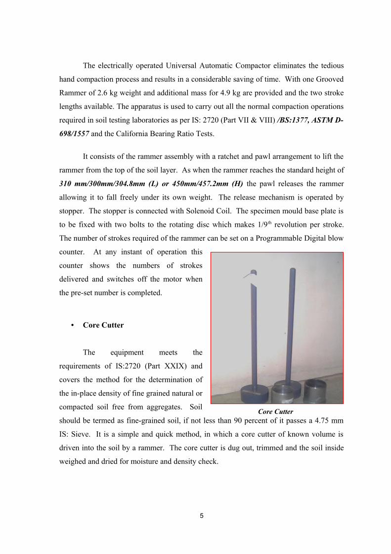
• Core Cutter
The equipment meets the
requirements of IS:2720 (Part XXIX) and
covers the method for the determination of
the in-place density of fine grained natural or
compacted soil free from aggregates. Soil
should be termed as fine-grained soil, if not less than 90 percent of it passes a 4.75 mm
IS: Sieve. It is a simple and quick method, in which a core cutter of known volume is
driven into the soil by a rammer. The core cutter is dug out, trimmed and the soil inside
weighed and dried for moisture and density check.
5
Core Cutter

Core Cutter having 10 cm internal diameters is made of seamless steel tube. It is
beveled and hardened at one end to form cutting edge. Dolly is made of steel and is
cylindrical in shape. Open from both sides, it is fitted with a lip to enable it to be located
on top of the core cutter. Rammer consists of a solid cylindrical base attached to a steel
stem.
• Sampling Auger Outfit
Sampling Auger Outfit is manufactured
for making auger borings and collecting the
representative samples at different depths. The
samples collected provide an idea of the different
soil layers for the preliminary examination.
The auger consists of a auger head,
extension rod, T-piece and a handle. The auger
head is made of two blades with cutting edges. The extension rod is of 1 metre length.
Number of extension rods can be coupled. (These
can be supplied on extra cost). The T-piece
screws on the extension rod are interchangeable.
• California Bearing Ratio Test Apparatus (Motorised)
It is used for the laboratory determination
of California Bearing Ratio and Expansion
Characteristics of undisturbed soil specimens
from the field and also of remoulded specimens of
the soil compacted in the laboratory by static or
dynamic compaction. All types of soils such as
sand, gravel and crushed stone can be tested. It is also used for the selection of material
and control of sub grade.
The equipment consists of a Load Frame of capacity 50 kN (500kgf), motorized
having three constant rates of strain.
6
California Bearing Ratio Test
Sampling Auger Outfit

This apparatus uses motorized load frame, other components are the same as
described above. Load Frame, Motorised, single speed is portable, sturdy and versatile.
Capacity of the unit is 50 kN (5000 kgf) and rate of travel of the lead screw is 1.25
mm/min. It operates on 230 volts, 50 Hz, single phase, AC supply.
• Density Basket
The equipment is used for determining
the specific gravity and water absorption of
aggregates larger than 10 mm. It is ruggedly
constructed from galvanized wire mesh
(approximately 6.3 mm). It has
approximately 20 cm dia x 20 cm height. It
has a carrying handle (hanger) for suspending
the basket from the balance.
• Aggregate Impact Tester with Counter
The equipment is manufactured to meet
the essential requirements of IS: 2386 Part IV
for determining the Aggregate Impact Value of
coarse aggregate. Aggregate Impact Value gives
a relative measure of the resistance of an
aggregate to sudden shock of impact. This
machine is furnished with a quick release trigger
mechanism to manipulate an impact with a free
fall of 13.75 kg hammer from a height of 380
mm ± 5 mm. It is supplied complete with one
cylindrical cup, one metal measure 75 mm dia x
50 mm deep tamping rod and automatic blow
counter.
The instrument is of rigid construction with a circular base over which the two
vertical steel guides are mounted. The guides are connected at the top by a metal plate
7
Density Basket
Aggregate Impact Tester

through which the adjustable stop for release of hammer and the locking pin operate. The
hammer slides up and down through vertical guides and is held by the release claw fixed
to the lifting handle. The height of the fall of the hammer can be adjusted through 380
mm ± 5 mm. The cylindrical steel cup can be fixed firmly to the base and is easily
removable for emptying. Another cylindrical metal measure of sufficient rigidity is used
for the preparation of the test sample which is compacted into measure using a tamping
rod.
• Los Angeles Abrasion Testing Machine
The equipment meets the essential
requirements of IS: 2386 (Part IV). This
equipment is for testing crushed rock,
crushed slag, crushed and uncrushed
gravel for resistance to abrasion. It also
meets the requirements of ASTM C 131
and ASSHO T96. The machine is suitable
for operation on 415 volts, 3 phase, 50 Hz,
AC supply.
It consists of a hollow drum
mounted on a sturdy frame, on ball bearings. There is an opening, which can be closed
with a dust tight cover to facilitate charging and discharging the drum with the material
under test. A detachable steel shell, which extends throughout the inside length of the
drum catches the abrasive charge and does not allow it to fall on the cover. The drum is
revolved by a geared electric motor at a speed of 30-33 rpm. A starter is fitted to switch
on or off the electric motor. The motor is operated on 415 volts, 3 phase, 50 Hz, AC
supply. The machine is so counter-balanced as to maintain a substantially uniform speed.
The drum is driven and can be rotated clockwise (facing from the drive side) by hand to
the desired position so that the opening can be brought down or up and the drum can be
discharged with the specimen. A tray is placed on the frame under the drum for collection
of the material at the end of the test. The gear box is to be filled with gear oil through the
8
Los Angeles Abrasion Testing Machine
oil filler plug. A drain plug is provided. The machine is provided with a revolution
counter.
• Stripping Equipment
The equipment is used for finding the
stripping value, bitumen adhesion and
durability of aggregates.
• Pycnometer
The equipment is used for finding the specific gravity of soil and bituminous
materials. This consists of the pycnometer with narrow and wide neck, 50 ml sp.gr
bottles, constant temp water bath and thermometer.
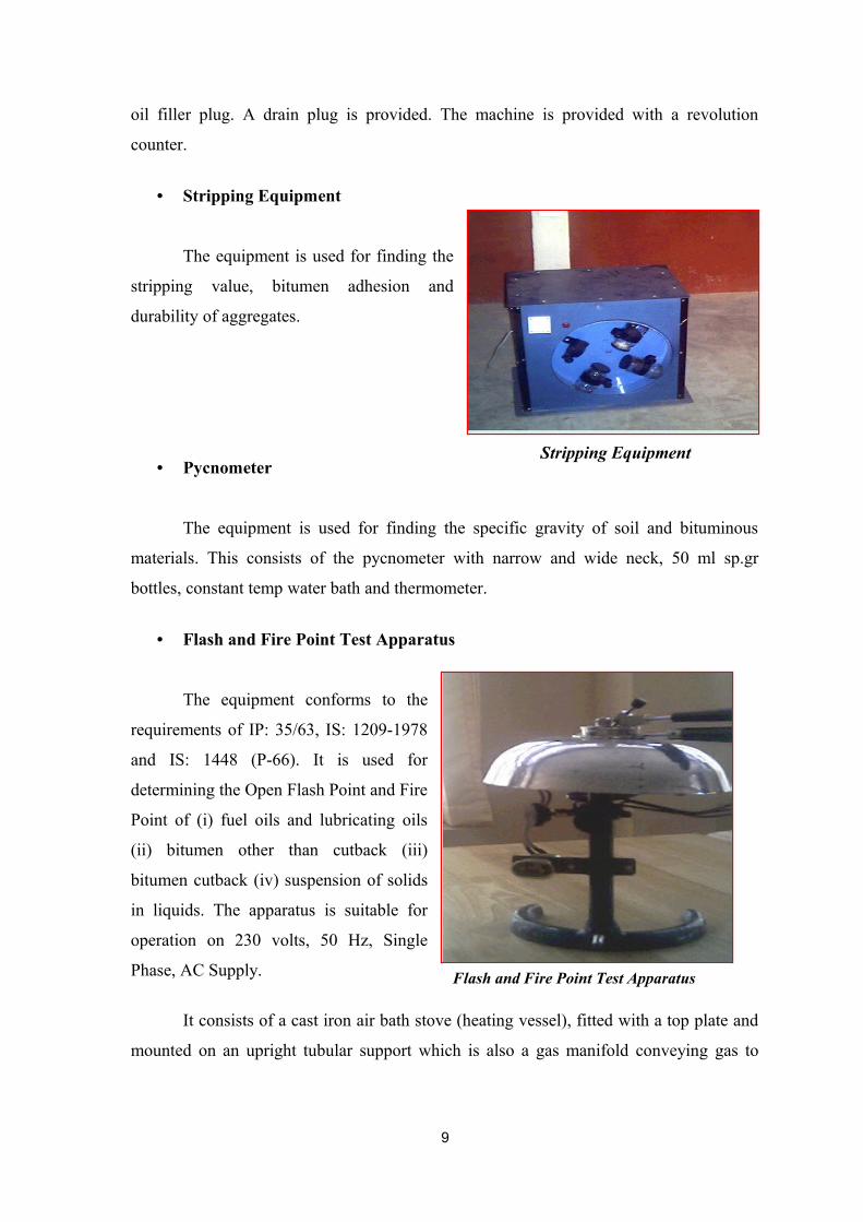
• Flash and Fire Point Test Apparatus
The equipment conforms to the
requirements of IP: 35/63, IS: 1209-1978
and IS: 1448 (P-66). It is used for
determining the Open Flash Point and Fire
Point of (i) fuel oils and lubricating oils
(ii) bitumen other than cutback (iii)
bitumen cutback (iv) suspension of solids
in liquids. The apparatus is suitable for
operation on 230 volts, 50 Hz, Single
Phase, AC Supply.
It consists of a cast iron air bath stove (heating vessel), fitted with a top plate and
mounted on an upright tubular support which is also a gas manifold conveying gas to
9
Flash and Fire Point Test Apparatus
Stripping Equipment
connections. Two of these connections are controlled by valves for use with test jet. A
ring support for the lid when not in use is an added convenience.
The oil cup has a lifting handle with heat insulating grip. Heating is achieved by a
heating coil fixed to the bath stove. Heating is regulated by the energy regulator.
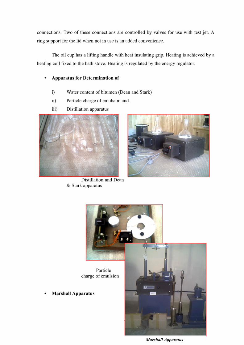
• Apparatus for Determination of
i) Water content of bitumen (Dean and Stark)
ii) Particle charge of emulsion and
iii) Distillation apparatus
Distillation and Dean & Stark apparatus
Particle charge of emulsion
• Marshall Apparatus
10
Marshall Apparatus

The equipment conforms to ASTMD-1559 and is meant for measurement of the
resistance to plastic flow of cylindrical specimens of bituminous paving mix containing
asphalt or tar and aggregate upto 2.54 mm. The results indicate the resistance of the mix
to withstand displacement under stress. The stability test is of considerable importance in
both design and control of mixes to withstand the tendency of flow or displacement. The
apparatus is suitable for operation on 230 volts, 50 Hz, single phase, AC supply.
The equipment comprises of a mould and collar which fits either end of the mould
during the compaction process. The mould fits on the base plate. The extractor with
spherical seating on the top moves freely inside the mould. The compaction hammer is
provided with a spring seating which acts as a shock absorber. The compaction pedestal
consists of a wooden post capped with 25.4 mm thick steel plate. It can be secured to a
solid concrete slab or to the floor. The specimen mould is to be in place during
compaction of the specimen. The top section is flanged to fit over the collar of the
specimen mould. It is attached to the base by means of a fulcrum on one side and a
tension spring on the other. Two holes are provided in the base for mounting on the
foundation pedestal.
The breaking head assembly consists of two jaws. The lower one is fixed to a
plate which the guide rods are fixed. The upper one moves freely on the guide rods. It
carries a top plate with a spherical seating to keep a steel ball, between the breaking head
assembly and proving ring.
The loading unit, electrically operated, is for operation on 230 volts, 50 Hz, AC
supply. It consists of a geared screw jack assembly enclosed in the frame which moves
the tension rods up and down. The travel of the tension rods is 50.8 mm/min. for
Marshall Apparatus and 61 mm/min. for Hubbard Field Test Apparatus. Speed change
handle is provided for setting the rates of travel, which are indicated on the plate fixed on
the side panel. The gearbox is connected to the motor through V-belt. A proving ring
adaptor is attached to the upper crosshead, which moves up and down with the tension
rods. The proving ring is fixed to the proving ring adaptor. An adaptor with a spherical
seating is fixed on the lower abutment of the proving ring and a steel ball is kept between
the proving ring and the breaking head while loading. The load is applied on the
specimen by the downward movement of the tension rods. A spirit level is attached with
the upper crosshead for leveling. Two limit micro-switches are provided to safeguard the
11

machine from any damage. The machine switches itself off when the cross-head reaches
the limit of its upward or downward travel and can be restarted only by reversing the
main ‘forward-reverse’ switch. These limit switches have been carefully positioned to
give the normal range of travel required in use. This setting should not be disturbed.
• Machine for Evaluating Roughness using Low Cost Instrumentation (Merlin)
The new instrument, which has been
developed, is a variation of the static profile-
measuring device. It is a manually operated
instrument, which is wheeled along the road
and measures surface undulations at regular
intervals. Readings are easily taken and there
is a graphical procedure for data analysis so
that road roughness can be measured on a
standard roughness scale without the need for
complex calculation. Its particular attraction for use is that it is robust, inexpensive,
simple to operate, and easy to make and maintain.
The device is called MERLIN, which is an acronym for a Machine for Evaluating
Roughness using Low-cost INstrumentation. It was designed on the basis of a computer
simulation of its operation on road profiles measured in the International roughness
Experiment (Sayers et al 1986a).
• Thermostatically Controlled Drying Oven
This has a temperature range of 0 to
1500C with internal dimension 600 x 600 x
600 mm with digital temperature controller.
12
Thermostatically Controlled Drying Oven
Modified Roughness Testing Machine (Merlin)

• Thermostatically Controlled Water Bath
This has got internal dimension of
750 x 500 x 250 mm with temperature
control.
• Proving Rings
A Proving Ring is an elastic load measuring device which, when used within the
elastic limits, obeys Hooke’s law. In other words, deflection (elongation or compression)
under load is proportional to the loading force.
The deflection of the Ring is measured by means of a very sensitive Dial Gauge
and a load versus deflection chart is given with the Ring showing the deflection at each of
ten equal load steps up to the maximum load capacity of the Ring.
In use, the deflection in division is read from the Dial Gauge and the
corresponding loading force is determined from the chart.
The ring is usually mounted by screwing it into an adapter fixed to the top of the
loading machine by the thread providing in the loading instrument. Normally self-
aligning action of either top or bottom loading platen of the loading machine is provided
by the manufacturer of the machine to allow for slight mis-alignments in the loading axis.
For rings upto 50 kN a steel ball and spherical seat nipple are provided and with the
nipple screwed into the lower abutment of the ring. The load is conveyed through the
steel ball for better self-aligning action. For rings above 50 kN capacity the flat face of
the lower abutment of the ring is used to convey the load. Greater reliance is placed on
the self-aligned action of the loading platen of the loading machine. With the ring in
13
Thermostatically Controlled Water Bath

position the test specimen is placed under it or (in the case of tension applications)
attached to it, the dial gauge reading set to zero on-off load condition. The load is
conveyed to the test piece through the ring.
If the loading process is continuous, as in a test to failure of a specimen, the
reading of the dial gauge is monitored and the maximum value of deflection observed.
By referring to the calibration chart provided, value of force corresponding to the
deflection is determined. Where the ring is used for loading in steps for calibration of
loading machines, it is recommended that as far as possible the same steps be used as
given in the calibration chart of the ring itself in order to eliminate any errors of
interpolation in reading from the chart.
• Balances (Automatic and Semi-automatic)
14

• Bump Integrator or Roughometer
Bump Integrator or Roughometer
gives speedily a quantitative integrated
evaluation of surface wheel with a
pneumatic tyre mounted on a chassis
over which an integrating device is fitted.
The machine has a panel board fitted
with Six digit digital counters for
counting the length in Meter and Bumps
in C.M.. The operating speed of the
machine is 32+1/2 km/hr. The machine is
towed by vehicle, usually a jeep.
Its wheel runs on the pavement surface and the vertical reciprocating motion of
the axle is converted into unidirectional rotary motion by the integration unit. The
accumulation of this unidirectional motion is recorded by operating Sensor inserted in the
circuit of six digit electronic counter, once for every 25 MM of accumulated unevenness.
Wheel revolutions are also indicated on
another electronic counter through Micro-Switch
actuated by the cam fitted on the hub of the
wheel. The two sets of counter readings give the
unevenness index value in terms of Cm/Km.
The Bump Integrator/Roughometer is
supplied with a pair of transportation wheels,
which will permit towing speeds up to 60 km/hr
without disturbing the accuracy of the
unevenness-measuring wheel.
• Penetration Test Equipment
15
Bump Integrator or Roughometer
Universal Penetro - MeterMeter

The equipment meets the requirements of IS 1203, IS 73 – IS 217 & IS 317. It is
used to grade bituminous binders in terms of their hardness. Depending on climatic
conditions and type of construction, bitumens of different penetration grades are used.
80/100 bitumen denotes that the penetration value ranges between 80 & 100.
The equipment consists of penetrometer, automatic electronic timer, standard set
of cups, transfer dish, needle, weights etc.
• Ductility Test Equipment
The equipment confirms to the requirements of IS
1203. It is used to measure ductility value of bitumen. In a
flexible pavement design, it is necessary that the binder
should form a thin ductile film around the aggregates so that
physical interlocking of the aggregates is improved.
The apparatus consists of briquette mould, ductility
machine thermometers etc.
• Ring and Ball Apparatus
This equipment is used to find out
the temperature at which the bituminous
binders attain a certain viscosity for various
road use applications. The equipment
consists of steel balls, brass rings, heat
resistant beaker, electric heater and energy
regulator, thermometers etc.
16
Ductility Test Equipments
Ring and Ball Apparatus

Standard Tar Viscometer
The equipment confirms to
the requirements of IS 1206. It is
used to find out the viscosity of
bitumen. The degree of viscosity at
the application temperature greatly
influences the ability of
bituminous material to spread,
penetrate into voids and also coat
the aggregates and hence affect
the strength characteristics of
resulting paving mixes. The
equipment consists of standard tar viscometer with electric heater, regulator,
thermometer 0 to 150 deg.C, with 10 mm & 4 mm orifice cups and ball valves.
• Core Drilling Machine
The equipment is used for taking out
cores of diameter 100mm from asphalt. The
core drilling machine is mounted on a sturdy
frame, which in turn is fixed on tow
Pneumatic Tyres. It can be easily towed
behind a jeep.
• Benkelman Beam Apparatus
17
Standard Tar Viscometer
Core Drilling Machine
Benkelman Beam Apparatus

The equipment meets the requirements of IS 81-1977. This equipment is a simple
and accurate device for measuring the deflection of flexible pavement under the action of
moving loads. The equipment consists of a slender beam of length 3.66m which is
pivoted to a datum frame at a distance 2.44m from the probe end. The datum frame
rests on a pair of front leveling legs and a roar leg with adjustable height. The probe end
of the beam is inserted between the dual rear wheels of the truck and rests on the
pavement surface at the centre of the loaded area of the dual wheel assembly. A dial
gauge is fixed on the datum frame with it’s spindle in contact with the other end of the
beam is such a way that the distance between the probe end and he fulcrum of the beam
is twice the distance between the fulcrum and dial gauge spindle.
A loaded truck with rear axle head of 8170 kg. is used for the deflection study.
Flexible pavement overlay thickness is
assessed by Benketman Beam method.
• Infrared Moisture Balance
The infrared moisture balance is an
instrument for measuring the moisture
content of materials that do not change their
chemical structure while losing water under
exposure to infrared radiations. This
instrument is widely used for testing soils
used in construction, agricultural soils,
chemicals, raw materials, foods,
pharmaceuticals, plashes and similar
materials.
Since drying and weighing are
simultaneous the Infrared Moisture Balance
is especially useful for determining
moisture percentage in substances that
quickly reabsorb moisture after drying.
The equipment consists of infrared
moisture balance and thermometer.
18
Centrifuge Extractor
Infrared Moisture Balance

• Centrifuge Extractor
The Centrifuge extractor is used for the quantitative determination of
bitumen in hot mixed paving mixtures and pavement samples. The centrifuge extractor
consists of a revolving bowl inside the housing.
• Calcium Carbide Test Apparatus
With this portable unit, the
moisture content of soil, sand clay
and other materials can be
determined in few minutes. It can
also be used to determine the
moisture contents of various types of
pastes, powders & mixes. The
equipment consists of a rapid
moisture meter, calcium carbide
bottles etc.
• Settlement test apparatus
The test is used for finding the
settlement of bitumen. The apparatus
consists of two 500ml graduated
cylinder with pressed or moulded
glass bases, cork or glass stoppers, a
60ml siphon, and glass tube pipette of
optional form.
• Coagulation test apparatus
19
Calcium Carbide Test Apparatus

The apparatus conforms to the essential requirements of IS:8887:1995. It is used
for determining the coagulation of emulsion at low temperature. It consists of 150mm
long glass boiling tube having 25mm internal diameter, provided with a cork and central
hole having 13mm diameter, a 600 micron IS sieve, two beakers of 600ml capacity and a
thermostatically controlled water bath.
• Test to determine residue on sieving on 600 micron IS sieve
The equipment consists of a
circular 600 micron IS sieve
approximately 100mm diameter and
40mm height, a small metal or glass
dish about 110mm diameter, a well
ventilated oven thermostatically
controlled to 100 to 110 0C, a litre
container, two balances, one of
capacity 250g and accuracy of 0.01g
and other of capacity 10kg and accuracy of 1g
• Solubility test
The test is used for the
determination of solubility and
bitumen in carbon disulphide. The
apparatus consists of gooch crucible,
conical glass flask of 200ml capacity
and solvent used is carbon disulphide
confirming to IS:717:1969.
• Thin film oven test
The method of test is intended
for the determination of loss on
20
heating of bitumen. The apparatus consists of an oven, perforated metal shelf,
thermometer and a container, which is a cylindrical pan of 140 mm inside diameter and
10 mm deep with a flat bottom.
• Determination of wax content in bitumen
This test is used for determining the
paraffin wax content of bitumen. The method
is applicable to bitumen having paraffin wax
with melting point above 25 0C. The
apparatus consists of a balance, Steam bath,
Oven, Bunsen burner, thermometers,
distillation flask, sheet metal guard ring,
cooling bath, test tubes, funnel, Erlenmeyer flask, test tube, filtering flask, vacuum pump
and evaporating dish.
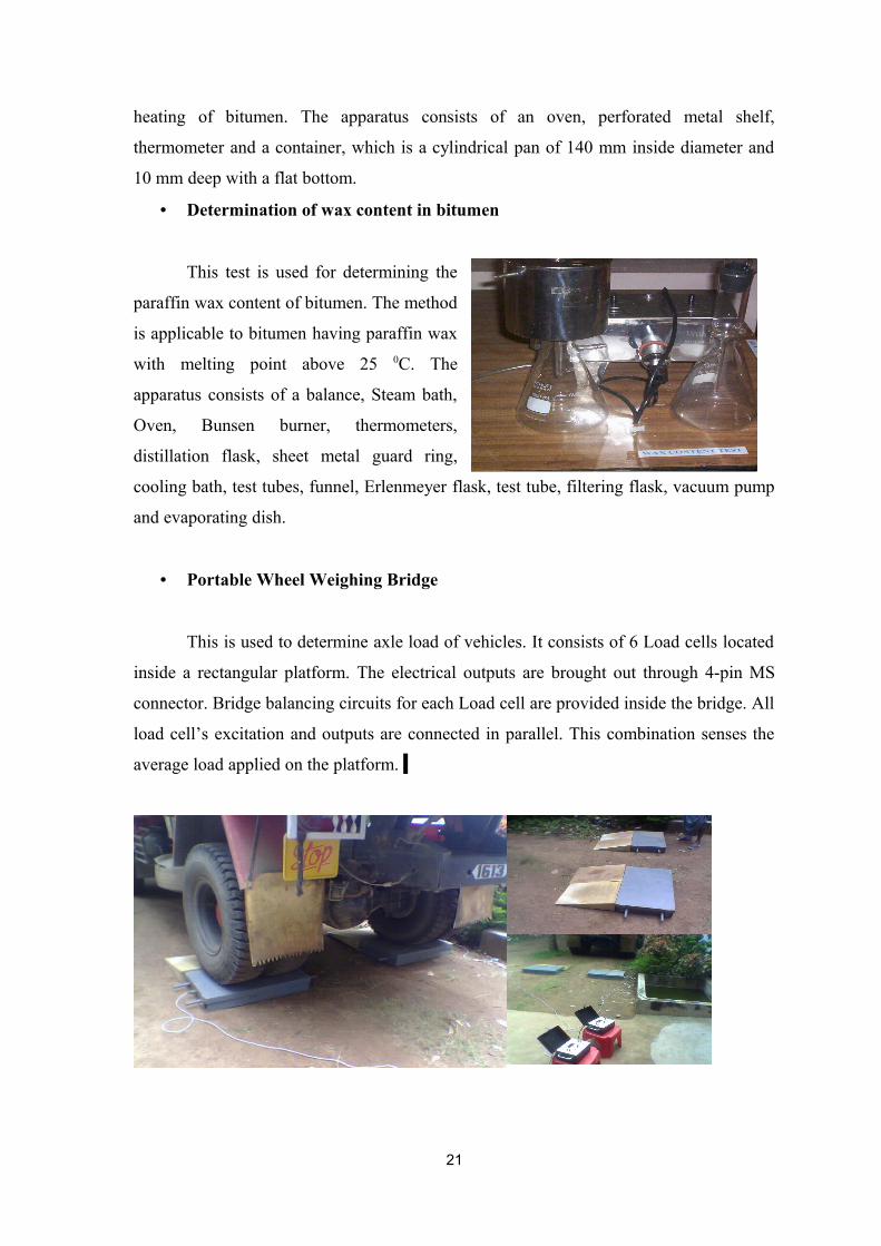
• Portable Wheel Weighing Bridge
This is used to determine axle load of vehicles. It consists of 6 Load cells located
inside a rectangular platform. The electrical outputs are brought out through 4-pin MS
connector. Bridge balancing circuits for each Load cell are provided inside the bridge. All
load cell’s excitation and outputs are connected in parallel. This combination senses the
average load applied on the platform.
21

The other accessories required for the test are Load cell and a load indicator. Load
cell is a transducer, which converts load into proportional electrical signals. Load
indicator is an accurate and sensitive instrument used for measuring loads employing
strain gauge based cells as sensor.
• Procurement of IS codes
The Indian Standard Codes published by Bureau of Indian Standards gives the
procedure for all the tests. The list of IS codes already procured is given in Appendix-
• Accessories
In addition to the main equipments, the accessories required for testing were
procured during the period. The list of items is given in Appendix IV.
Traffic Safety Cones
• Other Equipments
The lab has been provided with one ECHO SOUNDER for hydrographic studies,
two numbers of Total Stations and one DGPS for surveying purpose from the Head
office.
The models are given below:
1. Total Station 1- SOKKIA POWER SET 2010 with 2” accuracy with accessories and software.
2. Total Station 2-TOPCON 700 with 2” accuracy with accessories and software CIVILCAD Base Module.
3. GPS – LEICA DGPS SR 530Dual frequency Global Positioning system with base and rover set.
22

4. Echo Sounder – BATHY –500 DF Dual Frequency hydrographic Echo Sounder.
5. GPS Handset – MAGELLAN SPORTRAK handheld GPS
R & D PROJECTS UNDERTAKEN BY THE HIGHWAY ENGG. DIVISION AND LAB
The equipments in the Highway Engineering Laboratory are being utilized for the
research and sponsored projects under taken by the the division. The details of the
projects undertaken by the division are briefed below which establishes the utility of the
laboratory.
RESEARCH PROJECTS
Development of GIS technology enabled map server for Inland Waterways of Kerala-A Pilot Study
A GIS technology enabled map server was developed for the Inland Waterways.
This was a one year project under plan programme. Data collection included depth
measurement using echo sounder, laboratory testing of water and sediment samples and
23

geo referencing of the map using DGPS. The study made use of analytical and display
capabilities of GIS. The study stretch is the Kottappuram –Chettuva section of West
Coast Canal (53kms).The GIS map server presents geo-spatial data of Inland Waterways
in standardized format. Forty five layers are prepared which provide twenty five
coverages including various socio-economic and engineering aspects of the canal system.
The project enables effective sharing of IW information across agencies. It is a major step
for integrating IWT with the overall States transportation plan. The software developed is
user friendly and the frame work can be replicated to other stretches of WCC. The GIS
platform can be updated from time to time.
Development of Pavement Maintenance Management System(PMMS) for selected roads in Kerala.
The scope of the study is limited to carry out the performance evaluation studies
of selected road stretches for 3 years and
to develop models which can form input
to PMMS.
The project aims at development of
Unevenness Progression Model, Structural Deterioration model, Crack initiation &
propagation model& Pothole development and propagation model for pavements. Studies
on modified binders are also included as part of the project.
Attingal-Kallambalam
0
1
2
3
4
5
6
0
100
200
300
400
500
600
700
800
900
1000
1100
1200
1300
1400
1500
1600
1700
1800
1900
2000
Chainage (m)
Exte
nt o
f cra
cks
in %
of a
rea
24

To achieve this objective representative road stretches are selected across the
state and the evaluation studies are conducted on the same for 3 years.
Structural evaluation using Benkelman Beam deflection technique, functional
evaluation including condition Surveys, road Inventory, Skid resistance using Potable
Pendulum Skid resistance tester, Unevenness index using fifth wheel type Bump
Integrator, Road camber measurement-using camber board, evaluation of subgrade soil
properties like CBR, field Density by Sand replacement Method, Atterberg limits (Liquid
limit & Plasticity Index), Gradation by Sieve Analysis, Traffic surveys like axle load,
classified volume count etc. are included.
Data collection for Phase-II of PMMS project is progressing.
Feasibility Study For Integrated Development of Kottappuram –Chettuva Stretch of West Coast Canal
Inland Water Transport (IWT) is one of the widely accepted, energy efficient, safe
and eco-friendly mode. The Kottappuram Chettuva stretch of West Coast Canal having a
length of 53 kms form the immediate
extension of National waterway 3 from
Chettuva towards North
.
An integrated development of the section is
proposed to develop the stretch as a model
waterway and make the canal sustainable.
The first phase of the study which includes
data collection, analysis and prefeasibility is
completed. The second phase consisting of a
detailed study is in progress.
25

Study on navigability of feeder canals of Alappuzha region.
The study aims at identifying the feeder canal network of Alappuzha region &
assessing the canal system from the navigability point of view. Total Length of Feeder
canal network of Kerala is 960 kms. Alappuzha district alone account for 200 kms. It is
also proposed to carry out estimation of traffic potential, socio-economic aspects and
techno- economic aspects of the canal system. The study is in progress.
Suitability of locally available material for Road construction in Kerala
The scope of the project is to conduct studies for the suitability of locally available
materials for road construction in Coastal Kerala: by adding materials like red earth,
lateritic soil, crushed stone, quarry dust etc. The material most suitable for strengthening
the soil will be found out from the laboratory studies based on the improvements in
properties. Not much research has been done in this line specific to Kerala Coast for road
construction and the findings of the study will be helpful in identifying the appropriate
materials.
Ground Stabilization Techniques for Road Construction in Clayey Soils of
Kuttanadu Region
The study aims at identifying the road construction problems in Kuttanadu area
such as frequent surface failures & distress, settlement of embankments, failure of bridge
substructure due to settlement etc. The load bearing properties of clayey soils of
Kuttanadu region will be studied by conducting laboratory studies to suggest methods to
improve the same.
GIS application for Management of Bridges
The scope of the study is to design and formulate a data management system for
bridges in GIS platform. A user interface for easy access of the data base will be created
using ARC/INFO and Arc Macro Language. The GIS based bridge data base enhances
the flexibility of operations, eases the access of the required data and facilitates decision
26

making and can be used for asset management. Updation of the available data by field
inspection and geo referencing of the location using GPS is to be done before developing
the system.
SPONSORED PROJECTS
Roughness Studies for Roads Constructed under KSTP
This is a sponsored project
under taken for PWD. Roughness
studies for 6 road stretches of 140 kms
was done using Bump Integrator. The
result showed that the road stretches can
be categorized as good surface as per
the norms laid down by Indian Roads
Congress.
Improvement of Road connectivity to Tourist Locations in Kerala.
A project report for
improving the connectivity to
selected tourist locations in the state
has been prepared for tourism
department. The study helps the
tourism department to identify the
roads to be considered for
improvement and to take necessary
steps to implement the same based on a scientific ranking. Tourism department has
already taken action to implement the same.
27

Study of modified bitumen for road constructions in Kerala.
The study is sponsored by Rubber Board to evaluate the pavements constructed
and overlaid with rubber modified bitumen in Kerala and study the applicability of rubber
modified bitumen for Kerala condition. Comparative study of different types such as
NRMB, CRMB and PMB is also arrived at.
Pavement constructed or overlaid with rubber modified bitumen will be evaluated
functionally by conducting detailed condition survey, measurement of roughness using
Bump Integrator, measurement of skid resistance etc. Structural evaluation of the
pavement will be done by deflection studies using Benkelman Beam. The laboratory
studies include:
• Investigation of subgrade soil in order to determine subgrade soil properties such
as CBR, Field density, Plasticity index, Grain size analysis.
• Investigation on core extracted from the field to determine the effect of ageing on
bituminous binders.
• Test to determine properties of rubber modified bitumen such as NRMB, PMB,
and CRMB etc and compare their properties.
4. OTHER ACTIVITIES
Training to staff
In house training / demonstration was conducted for the staff attached to the
division for a period of one month in October as part of the installation of equipments.
Services of faculty from college of Engineering, Thiruvananthapuram were utilized for
the same. The programme was held from 4pm to 6pm on working days.
Special Training to Engineers
28

One Civil Engineer was selected from a panel of 16 Engineers who were working
in NATPAC under different schemes based on a written test followed by interview and
was sponsored for a PG Certificate course on ‘Road Technology ‘ approved by
Visveswaraya Technological University and conducted by IR RASTA, Bangalore. The
duration of the course was six months and the person joined NATPAC and is attached to
the division in May 2005 after successfully completing the course with first rank.
29

30


