High-Speed Serial InterfaceCircuits and Systems
Design Exercise3 –
LC VCO
High-Speed Circuits and Systems Lab., Yonsei University
LC VCO Structure
High-Speed Circuits and Systems Lab., Yonsei University2
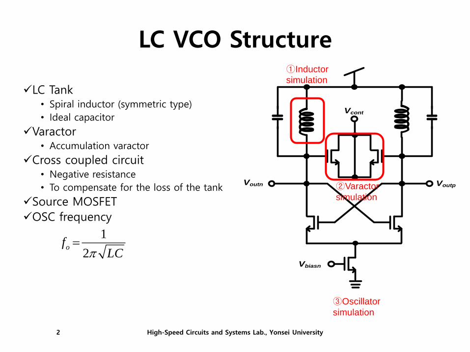
✓LC Tank • Spiral inductor (symmetric type)
• Ideal capacitor
✓Varactor • Accumulation varactor
✓Cross coupled circuit • Negative resistance
• To compensate for the loss of the tank
✓Source MOSFET
✓OSC frequency
1
2of
LC
Voutn
Vbiasn
Voutp
Vcont
①Inductor
simulation
②Varactor
simulation
③Oscillator
simulation

Design Example
✓ LC voltage controlled oscillator (VCO)- Supply voltage: 1.8V
- Frequency tuning range: > 30-MHz
- Oscillation frequency : 1.5-GHz
- Phase noise @ 1-MHz offset with 1.5-GHz: < -125dBc
High-Speed Circuits and Systems Lab., Yonsei University3

Inductor Model
High-Speed Circuits and Systems Lab., Yonsei University4
• An equivalent circuit model of inductor • Series connection of resistance and inductance
• Analyze inductance into using Z-parameter
< Equivalent circuit of inductor >
< Simulation schematic >

Inductor
High-Speed Circuits and Systems Lab., Yonsei University5
• Inductor selection• Tsmc18rf → RF_Device → Inductor → ind_sym → symbol
• Symmetric inductor selection
Inductor PDK
High-Speed Circuits and Systems Lab., Yonsei University6
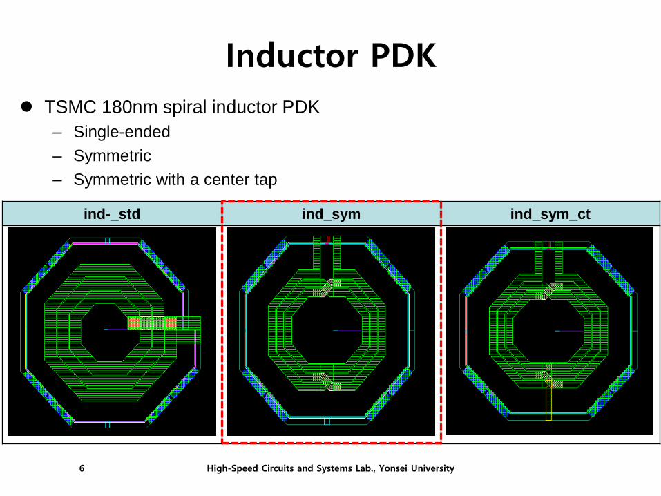
TSMC 180nm spiral inductor PDK
– Single-ended
– Symmetric
– Symmetric with a center tap
ind-_std ind_sym ind_sym_ct
Inductor Parameters
High-Speed Circuits and Systems Lab., Yonsei University7
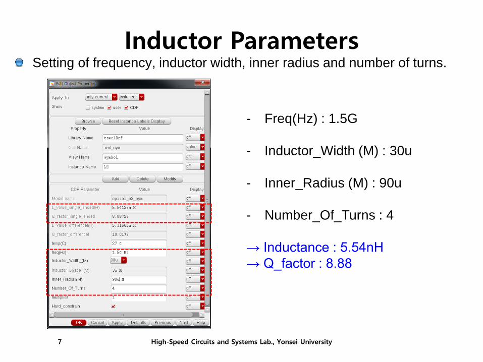
Setting of frequency, inductor width, inner radius and number of turns.
- Freq(Hz) : 1.5G
- Inductor_Width (M) : 30u
- Inner_Radius (M) : 90u
- Number_Of_Turns : 4
→ Inductance : 5.54nH
→ Q_factor : 8.88
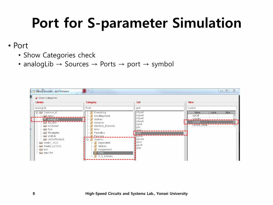
Port for S-parameter Simulation
High-Speed Circuits and Systems Lab., Yonsei University8
• Port • Show Categories check
• analogLib → Sources → Ports → port → symbol

S-parameter Simulation Setup
High-Speed Circuits and Systems Lab., Yonsei University9
• Simulation condition setting • Analysis : sp (S-Parameter Analysis)
• Ports : Port0 (schematic node choice)
• Sweep Variable : Frequency
• Sweep Range : 100M ~ 4G
• Sweep Type : Logarithmic
• Number of Steps : 300
• Enabled check → OK → Netlist and Run
4G100M
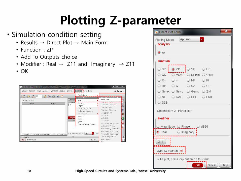
Plotting Z-parameter
High-Speed Circuits and Systems Lab., Yonsei University10
• Simulation condition setting • Results → Direct Plot → Main Form
• Function : ZP
• Add To Outputs choice
• Modifier : Real → Z11 and Imaginary → Z11
• OK
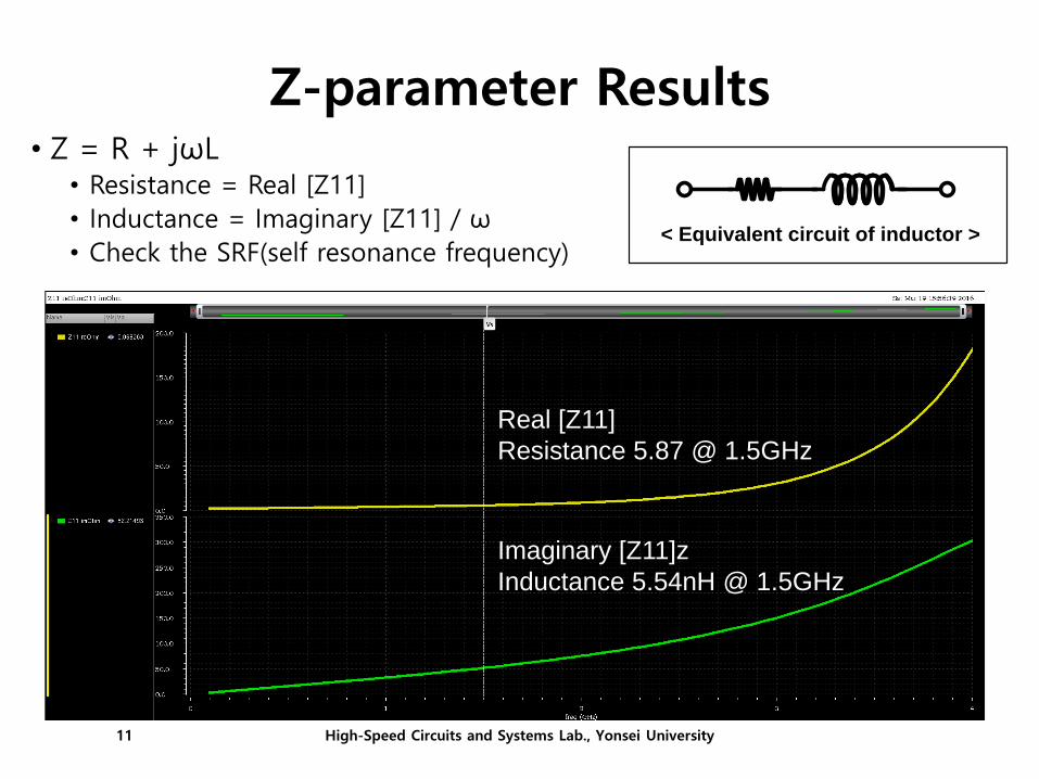
Z-parameter Results
High-Speed Circuits and Systems Lab., Yonsei University11
• Z = R + jωL • Resistance = Real [Z11]
• Inductance = Imaginary [Z11] / ω
• Check the SRF(self resonance frequency) < Equivalent circuit of inductor >
Real [Z11]
Resistance 5.87 @ 1.5GHz
Imaginary [Z11]z
Inductance 5.54nH @ 1.5GHz
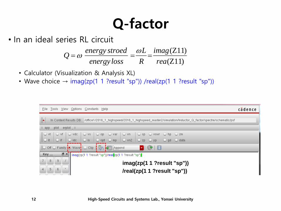
Q-factorPhase response
High-Speed Circuits and Systems Lab., Yonsei University12
• In an ideal series RL circuit
• Calculator (Visualization & Analysis XL)
• Wave choice → imag(zp(1 1 ?result "sp")) /real(zp(1 1 ?result "sp"))
imag(zp(1 1 ?result "sp"))
/real(zp(1 1 ?result "sp"))
(Z11)
(Z11)
energy stroed L imagQ
energy loss R rea
Q-factor Results
High-Speed Circuits and Systems Lab., Yonsei University13
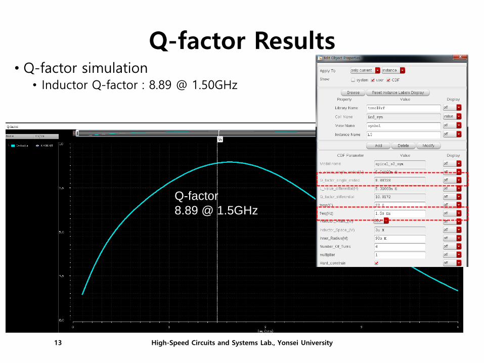
• Q-factor simulation • Inductor Q-factor : 8.89 @ 1.50GHz
Q-factor
8.89 @ 1.5GHz

Accumulation Mode Varactor• On (Accumulation)
• OFF (Depleted)
C
VGS
Accumulation
(Cox)
Depletion
Nsub
Nsub
High-Speed Circuits and Systems Lab., Yonsei University14

Oscillator with Varactor
Voutn
Vbiasn
Voutp
Vcont
C
VGS
Accumulation
(Cox)
Depletion
VDD
Voutp
• Change average capacitance from control voltage.
High-Speed Circuits and Systems Lab., Yonsei University15

Varactor• Varactor selection
• Tsmc18rf → Varactor → Varactor_RF → mos_var → symbol
High-Speed Circuits and Systems Lab., Yonsei University16
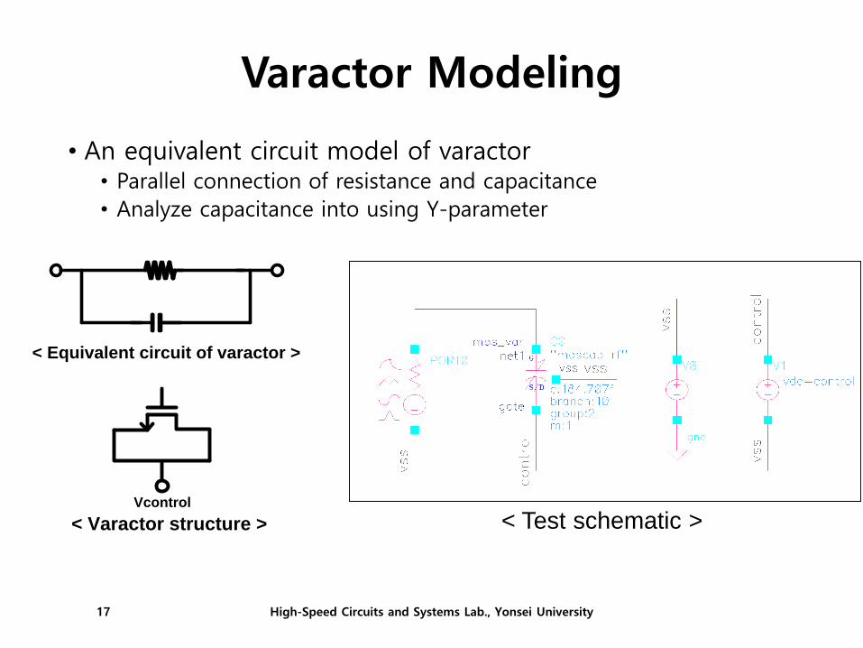
Varactor Modeling
• An equivalent circuit model of varactor • Parallel connection of resistance and capacitance
• Analyze capacitance into using Y-parameter
< Test schematic >
< Equivalent circuit of varactor >
Vcontrol
< Varactor structure >
High-Speed Circuits and Systems Lab., Yonsei University17

S - Parameter• Simulation condition setting
• Analysis : sp (S-Parameter Analysis)
• Ports : Port0 (schematic node choice)
• Sweep Variable : Frequency
• Sweep Range : 100M ~ 40G
• Sweep Type : Logarithmic
• Number of Steps : 300
• Enabled check → OK → Netlist and Run
High-Speed Circuits and Systems Lab., Yonsei University18
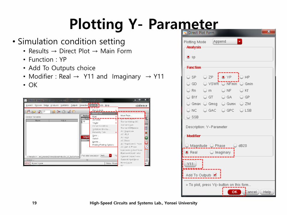
Plotting Y- Parameter• Simulation condition setting
• Results → Direct Plot → Main Form
• Function : YP
• Add To Outputs choice
• Modifier : Real → Y11 and Imaginary → Y11
• OK
High-Speed Circuits and Systems Lab., Yonsei University19
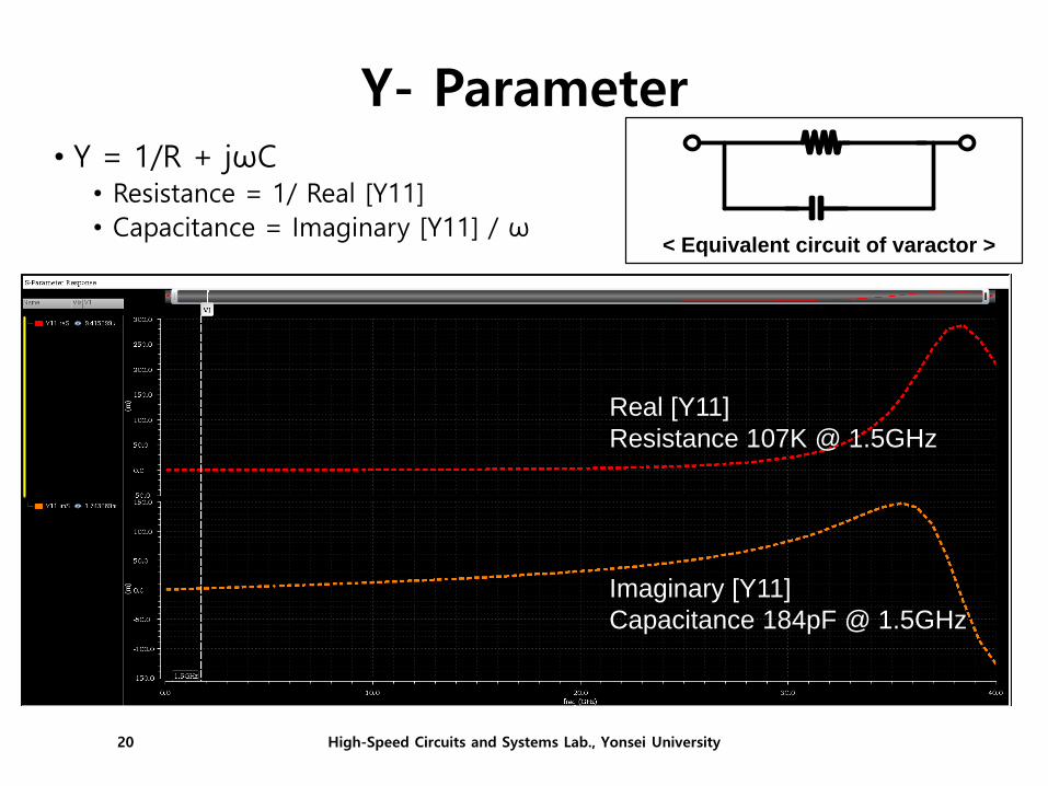
Y- Parameter• Y = 1/R + jωC
• Resistance = 1/ Real [Y11]
• Capacitance = Imaginary [Y11] / ω
Real [Y11]
Resistance 107K @ 1.5GHz
Imaginary [Y11]
Capacitance 184pF @ 1.5GHz
< Equivalent circuit of varactor >
High-Speed Circuits and Systems Lab., Yonsei University20
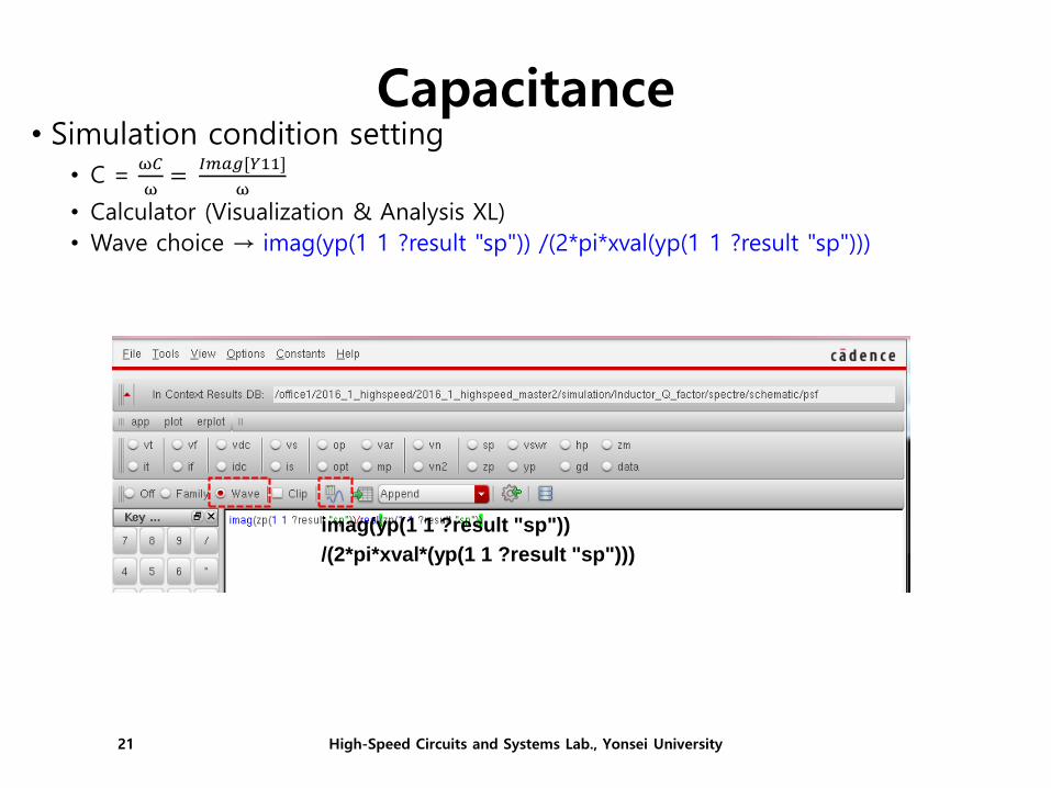
Capacitance• Simulation condition setting
• C = ω𝐶
ω=
𝐼𝑚𝑎𝑔[𝑌11]
ω
• Calculator (Visualization & Analysis XL)
• Wave choice → imag(yp(1 1 ?result "sp")) /(2*pi*xval(yp(1 1 ?result "sp")))
imag(yp(1 1 ?result "sp"))
/(2*pi*xval*(yp(1 1 ?result "sp")))
High-Speed Circuits and Systems Lab., Yonsei University21
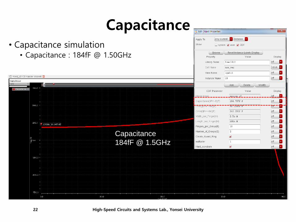
Capacitance• Capacitance simulation
• Capacitance : 184fF @ 1.50GHz
Capacitance
184fF @ 1.5GHz
High-Speed Circuits and Systems Lab., Yonsei University22
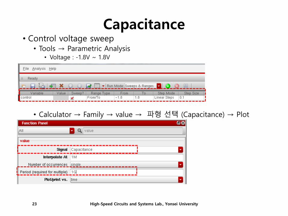
Capacitance• Control voltage sweep
• Tools → Parametric Analysis • Voltage : -1.8V ~ 1.8V
• Calculator → Family → value → 파형 선택 (Capacitance) → Plot
High-Speed Circuits and Systems Lab., Yonsei University23
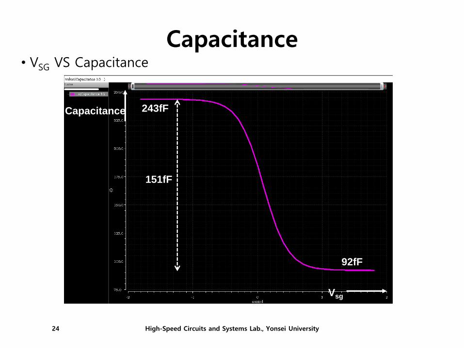
Capacitance• VSG VS Capacitance
Capacitance
Vsg
1.45GHz
243fF
92fF
151fF
High-Speed Circuits and Systems Lab., Yonsei University24

LC VCO Schematic
• Simulation LC VCO schematic• Inductor : 5.42nH
• Capacitor : 1.5pF
• Input NMOS
• Length : 180n
• Total Width : 20u (finger :1)
• Source NMOS
• Length : 500n
• Total Width : 100u (finger :1)
• Varactor
• vdd : 1.8V
• biasn : 0.8V
• cont : 변수 지정 (cont)
• Initial conditionoutp & outn:1.8V, 1.85V
High-Speed Circuits and Systems Lab., Yonsei University25

OSC Frequency (Vcont = 0V)• Control Voltage 0V
• OSC frequency : 1.36GHz
• Transient simulation (100ns)
• Output 파형 및 Frequency 측정
1.47GHz @ Vcont 0V
High-Speed Circuits and Systems Lab., Yonsei University26

OSC Frequency (Vcont = 1.8V)• Control Voltage 1.8V
• OSC frequency : 1.36GHz
• Transient simulation (100ns)
• Output 파형 및 Frequency 측정
1.51GHz @ Vcont 1.8V
High-Speed Circuits and Systems Lab., Yonsei University27
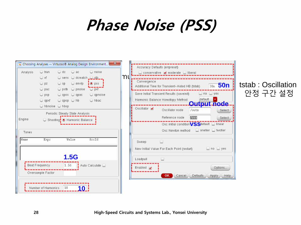
Phase Noise (PSS)
• PSS• Periodic Steady-State simulation
tstab : Oscillation
안정 구간 설정
1.5G
10
50n
Output node
vss
High-Speed Circuits and Systems Lab., Yonsei University28

Phase Noise (Pnoise)• Pnoise
• Setup PSS first, then Pnoise
Output : Voltage 설정Output Node 설정
Input : none
10M1K
1
300
30
Output node
vss
High-Speed Circuits and Systems Lab., Yonsei University29

Phase Noise
• Phase noise • Calculator (Visualization & Analysis XL)
• Function Panel (phaseNoise 입력) • Harmonic Number : 1
• Signal dataset : pss_fd
• Noise dataset : pnoise
• Apply
High-Speed Circuits and Systems Lab., Yonsei University30

Phase Noise
• Phase noise • Vcont = 1.48V
• 1.5GHz, -129.9dBc @ 1MHz
1.5GHz , -129.9dBc @ 1MHz
High-Speed Circuits and Systems Lab., Yonsei University31

✓ Design 2-GHz (±100MHz) LC VCO with tuning range larger than 100MHz
✓ Verify and plot output waveforms and KVCO.
✓ Verify and plot phase noise with control voltage generating 2-GHz clock.
✓ Indicate LC VCO schematic, inductor and capacitor value, and using varactor
count in the report.
✓ LC VCO specification
-Supply voltage : 1.8V
-Load capacitance: 1.5 pF
-Phase noise : Min -115dBc/Hz
-Frequency tuning range : Min 100MHz
✓ Due: 25 Sep. in class (Hardcopy)
High-Speed Circuits and Systems Lab., Yonsei University32
Homework


