
Technical Papers SyllabusHigh-Rise Building Solutions
01/2019

Manage water for better high-rise livingwww.aliaxis.com/high-rise
2
Preface
It is estimated that by 2020 there will be an additional 1.3 billion people on this planet. Most of them will live in large metropolitan areas with more than 10 million inhabitants. In increasingly dense city areas most people will live in high-rise apartment buildings.
These buildings must incorporate new and innovative high-rise building solutions to address the unique infra-structural challenges of tall buildings, and to ensure that high-rise living is made more feasible, comfortable, green, safe and affordable.
The sheer height of a building changes the physical forces applied to plumbing systems, meaning conventional designs are no longer up to the job. This relates to pressure piping in the water supply system and, more importantly, to the drainage system. In a high-rise building, a well-designed drainage system should operate without the user being aware of its existence.
This syllabus of technical papers gives a comprehensive overview of all the research done and relevance as to why new solutions are required. It covers the important design aspects, offers Aliaxis solutions, and discusses fire safety in relation to material choices.
Aliaxis high-rise building solutions - Manage water for better high-rise living.
Preface
Research Relevance
Design Solutions
Materials Installation
Terminology Standards

Manage water for better high-rise livingwww.aliaxis.com/high-rise
3Table of Contents
Table of Contents
Preface 2Table of contents 3
ResearchCurrent venting diameters for high-rise drainage ventilation 7National Lift Tower 13Rainfall intensity used for siphonic rain water drainage 17What flow rates can go through a drainage system 23What happens at the base of the stack 31
RelevanceAbove ground drainage and vent systems 37Air pressure transients in drainage systems 41High-rise design practice and codes 45Purpose of a high-rise drainage and ventilation system 51Requirements for a well-designed high-rise drainage system 55Water trap seal 59
DesignLimiting roof penetrations in high-rise buildings 64Offsets in building drainage systems 71Vertical flow in high-rise drainage systems 75
SolutionsActive ventilation single stack drainage 81Air Admittance Valves (AAVs) 87Siphonic rainwater drainage 93Siphonic roof drainage systems 97Stack-aerator system principles 103
MaterialsDWV systems and fire safety 109
About the AuthorsSteven White 114Marc Buitenhuis 114
About Our Hydro-Dynamics Experience CentresHydro-Dynamics Experience Centre 115The National Lift Tower 115Heriot-Watt University 115
NotesNotes 116


Research• Current venting diameters for high-rise drainage ventilation
• National Lift Tower
• Rainfall intensity used for siphonic rain water drainage
• What flow rates can go through a drainage system
• What happens at the base of the stack
Manage water for better high-rise livingwww.aliaxis.com/high-rise
5


High-rise building solutions
Technical paper
Current venting diameters for high-rise drainage ventilation
Available research, simulation data and code guidance
Steve White
Technical Director DWVAliaxis High-Rise Building SolutionsUnited Kingdom10/2017
Context of this paper
This technical paper is part of a library of technical papers. Refer to the below overview of all our technical papers and click on the title for a digital link.
Abstract
In the last 20 years the Drainage Research group of Heriot Watt University as well as other leading research universities around the world have been researching the venting requirements for high-rise drainage and in particular the correct requirements for drainage venting of these buildings. The current findings of the research proves that the current guidance with national codes do not meet the requirements for safe venting in high-rise buildings.
Research Relevance Design Solutions Materials Installation Terminology Standards

Manage water for better high-rise livingwww.aliaxis.com/high-rise
8
Introduction
The requirement for research is always important in every aspect in a developing world. In the construction industry one of the least invested and researched disciplines is the above ground drainage and in particular the venting requirements for high-rise buildings, verses other disciplines - for example structural and heating and ventilation.
The current national regulations and code guidance is based on research carried in the 1950s-1960s and changes to the guidance in the codes takes many years to achieve. For codes and guidance to be changed research is required, and this can only be achieved with industry support.
The Drainage Research Group at Heriot Watt University is one of the world’s leading institutions in researching drainage and drainage ventilation. The ability to model what happens in the drainage system is a key tool to help understand what is or will happen in drainage systems and the requirements for a safe working system, tools such as AIRNET allow modeling of high-rise systems and much of the research has been peer reviewed and published. This paper is focusing on the findings of the research in regards to the correct requirements for passive drainage venting requirements for tall buildings, based on modelling and the fluid mechanical calculations behind the research.
AIRNET In 1989, Heriot Watt University developed the mathematical simulation model AIRNET. The development and research for the simulation model undertook extensive site testing to build a database of system pressure in response to applied flows; the development from the database of fundamental shear force relationships that define entrained airflows; the development and incorporation of a database of system boundary conditions compatible with a method of characteristics of network operation, into AIRNET.
This now provides a comprehensive simulation methodo-logy that provides the system designer with the means to predict the likely pressure regime and entrained airflows conditions. This will also allow a re-elevation of the codified design guidance currently available in national codes for high-rise buildings.
Current venting diameters for high-rise drainage ventilationAvailable research, simulation data and code guidance

Manage water for better high-rise livingwww.aliaxis.com/high-rise
9
Current Guidance for High-rise Drainage Venting
Code guidance in the main recommends drainage ventilation with the vent pipes smaller or at the most the same diameter as the wet stack and all represent ‘passive’ control and suppression, as there is no interaction between the control mechanism, the fixed in place vent, and the transient. Two basic principles of surge suppression have been identified –
1. Transients may be attenuated by reducing the rate of change of flow velocity. This implies that the flow should be diverted in the case of a positive transient or, in the case of a negative transient added through an adjacent inlet.
2. The second basic principle is that the surge alleviation should be positioned between the source of the transient and the equipment to be protected.
Figure 1.Traditional drainage ventilation
While the fixed in place vent solution provides a degree of flow diversion or addition, criteria 1 above, its efficiency in this role is limited by fundamental misunderstandings of the operating mechanism of the vent stack currently embedded in the codes.
Fixed in place vents do not meet the second criteria in any way. The source of any relief to offset the pressure regime imposed on the system by the passage of the transient is the reflection of the transient at the upper open termination of the vent system. Thus the potentially trap seal depleting transient pressures have already passed all the traps to be protected before any relieving reflection can be generated by the open termination.
Current venting diameters for high-rise drainage ventilationAvailable research, simulation data and code guidance

Manage water for better high-rise livingwww.aliaxis.com/high-rise
10
Current research
The pressure transient transmission and reflection coefficients at junctions may be determined from the following expressions (Swaffield and Boldy 1993).
Figure 2.Transient transmission and reflection coefficients
It will be seen from equations 8 and 9 that the wave speed in each pipe or duct is included in the coefficient deter-mination, however in the case of low amplitude air pressure transient propagation in building drainage and vent systems the pipework may be taken as rigid and the wave speed in air as constant, simplifying the equations.
Similarly it will be seen that the transmission and reflection coefficients depend upon the identification of the pipe carrying the incoming transient. The junction will present different coefficients for transients arriving along the branch or the continuation pipe. Thus equations 8 and 9 have been re-cast in terms of the pipe carrying the incoming transient (pipe 1 in Figure 3), the branch (pipe 2 in Figure 3) and the continuation pipe (pipe 3 in Figure 3) as this will make calculation of the coefficients easier.
Figure 3.Transmission and reflection of a transient at a three pipe junction.
The transmission coefficient at a junction of three equal diameter pipes is 66% of the incoming wave, Figure 4. A -33% reflection of the incoming is also generated. If the branch vent, Pipe 2 in Figure 3, is reduced in diameter then the transmitted wave strength increases – e.g. if the vent is half wet stack diameter then the transmitted wave is increased to 90% of the incoming wave. This offers no reduction in the transient propagating up the wet stack. If the vent has a greater diameter than the wet stack then the vent system starts to have an influence on the transient propagated up the building, e.g. if the vent stack is double the wet stack diameter then the transmission reduces to 33%. Note that the diameter of the cross vent, Figure 3, is as important as the vent diameter in restricting wave attenuation.
All national plumbing codes suggest equal or smaller diameter vent stacks compared to the wet stack, hence there is a fundamental misunderstanding of the mechanism of surge protection embedded in the design codes.
Current venting diameters for high-rise drainage ventilationAvailable research, simulation data and code guidance

Manage water for better high-rise livingwww.aliaxis.com/high-rise
11
Figure 4.Influence of branch to stack diameter ratio
The transmission and reflection coefficients at a three pipe junction depend upon the relative area ratios of the joining pipes. Figure 3 illustrates the necessary equations defining these coefficients.
It is the ratio of the pipe cross sectional areas that determines the coefficients rather than actual pipe diameters. If the traditional passive venting of individual traps back to the vent stack is considered, Figure 5, then it will be appreciated that a small diameter vent connected into the trap branch will have little effect.
Figure 5.Different pipe cross sectional areas
Figure 6.Effectively reducing pressure
Current venting diameters for high-rise drainage ventilationAvailable research, simulation data and code guidance

Manage water for better high-rise livingwww.aliaxis.com/high-rise
12
Conclusion
Using current research and tools for modelling drainage systems such as AIRNET, provide evidence that there is a requirement to re-evaluate the requirements of the size of venting for passive drainage ventilation. The undersizing of the vents, do not meet the basic two principles of surge suppression. Only by increasing the size of the vents so that they are larger than the wet stacks will the principles be met for passive venting in high-rise building. Alternately active drainage ventilation and stack-aerators, both single stack high-rise drainage stack system could be used and meet the requirements of the two key principles without the need to the vent pipes and the requirement to enlarge them.
Steve WhiteTechnical Director DWVAliaxis High-Rise Building Solutions
MSc (Ir.) Marc Buitenhuis MTDResearch Engineer Hydro-DynamicsAliaxis
09
/17/
129
1. BSI British Standard Institution (2004). European Standard BS EN 12056-2:2000
2. International Code Council (2003). US Standard International Plumbing Code-IPC
3. International Association of Plumbing and Mechanical Officials (2003). US Standard Uniformed Plumbing Code-UPC
4. Standard Australia (2003). Australian Standard AS/NZS 3500.2-2003
5. Wang Xuejiao (2007). Study on flux capacity of single stack drainage system: Non-Roof, Penetration Self Circulating Drain System Stack Tongji University
6. Prof J.A. Swaffield, Dr L.B. Jack, Dr D.P. Campbell (2006). The Active Control and Suppression of Air Pressure Transients within the Building Drainage System. Studor commissioned report.
7. Prof J.A. Swaffield, Dr M. Gormley (2006). Comparisons of Venting Options under positive and negative pressure transients for a 50 storey building using numerical model AIRNET. Studor commissioned report.
8. Swaffield JA (2010). Transient Airflow in Building Drainage Systems, published by Spon Press
Read more technical papers related to this subject
• Design - Offsets in Building Drainage systems• Design - Vertical Flow in High-rise Drainage Systems• Relevance - Above ground drainage and vent systems• Relevance - Air Pressure transients in drainage systems• Relevance - High-rise design practice and codes• Relevance - Purpose of a High-Rise Drainage and Ventilation system
Current venting diameters for high-rise drainage ventilationAvailable research, simulation data and code guidance

High-rise building solutions
Technical paper
National Lift Tower
The world’s tallest drainage test facility “Seeing is Believing”
Steve White
Technical Director DWVAliaxis High-Rise Building SolutionsUnited Kingdom10/2017
Context of this paper
This technical paper is part of a library op technical papers. Refer to the below overview of all our technical papers and click on the title for a digital link.
Abstract
The ability to test drainage systems for the types of buildings being built today is important, to ensure that the drainage system works as designed. For high-rise buildings 30, 50 floors or more the design and materials used should be tested, to meet the loadings and usage patterns for these buildings, to ensure the waste is removed as quickly, self-cleansing and that the barriers provided by water trap seals are maintained. The 1950-1970 testing that forms the basis for many national codes carried out physical testing on buildings of that era, so the testing for high-rise buildings was carried out for 10 to 25 floors. How can the data from these tests meet the demands for taller buildings? Since the late 1970 researchers have been able to model drainage systems for high-rise buildings and provide valuable data and findings, but the ability to have a high-rise test platform provides confidence to the industry that the materials and systems used work, which helps validate the modelling research.
Research Relevance Design Solutions Materials Installation Terminology Standards

Manage water for better high-rise livingwww.aliaxis.com/high-rise
14
Introduction
The National Lift Tower (NLT) in the United Kingdom is a building that is 127.45 metres (418.1 feet) tall, 14.6 m (47.9 ft) in diameter at the base and tapers to 8.5 m (27.9 ft) at the top.
Due to the height of this test facility, it is ideal for testing drainage and vent systems solutions for tall buildings. It is currently the tallest drainage test facility in the world.
Within the facility the drainage systems can be tested representing a 40 floor drainage system. The space within the building allows different drainage solutions to be compared, and for current code recommendations to be tested for the demands of high-rise buildings.
Why is testing required?
The first thing to understand about drainage codes, is that they are mainly based on “old-research” carried out in the 1950 and the 1960, with the majority of the research undertaken at the Bern Switzerland, and in the United Kingdom. Although there have been early research for tall buildings, the buildings tested had limited discharging of appliances.
• In Europe, the Vocational training school in Bern, realised a joint research with a number of European groups, CSTB (France), CSTC (Belgium), SIB (Sweden), IBT Germany and SVGW (Switzerland) based on testing on a 10-floors building.
• In the United Kingdom, the BRE studies were undertaken at first on 5 floor buildings and, in the 1960s, moved to 10 floor buildings with 100 mm stacks and 25 floor buildings with 150 mm stacks. This research was based on data collected from buildings and laboratory testing and was published as a code of practise in the early 1970s.
• In the United States the codes are based on research from the 1930s mainly through the work of Hunter.
Also, all these researches have been based on steady state conditions, meaning that they focused on the applied water flowrates to drain diameters and slope. The drainage and vent system also has air and the time dependent water flows within the drainage network entrain an airflow that is therefore itself unsteady.
So current codes are based on old data, research on limited height buildings (10 to 25 floors) and on steady- state conditions, to understand system performance for modern day high-rise buildings testing must be conducted. Figure 1. Figure 2.
National Lift Tower The world’s tallest drainage test facility “Seeing is Believing”

Manage water for better high-rise livingwww.aliaxis.com/high-rise
15
Setup
The vertical shafts allow for different pipes systems and configurations to be installed. Due to the access that the facility provides it is also ideal for carrying out live demonstrations (seeing is believing).
Figure 3.
The current configuration in the tower is based on the EN12056-2, with a one floor stub stack and a 5 meter offset, with 100 meters of vertical stack above this.
Figure 4.
The current configuration in the tower is based on the EN12056-2, with a one floor stub stack and a 5 meter offset, with 100 meters of vertical stack above this.
The stack diameter 100 mm, with a 50 mm secondary vent with cross vents every 3 floors. The vent pipes can be isolated from the stack using gate valves. Active venting is also installed on the system consisting of AAVs and P.A.P.A. so that the systems can be compared.
Figure 5.
Pressure transduces are also installed so that the pressure in the pipes and different locations can monitored and recorded.
Figure 6.
Figure 7.
National Lift Tower The world’s tallest drainage test facility “Seeing is Believing”

Manage water for better high-rise livingwww.aliaxis.com/high-rise
16
Conclusion
The NLT provides the perfect platform for testing modern high-rise drainage and vent systems, both to code designs as well as different system solutions such as active drainage ventilation and stack-aerators.
The validation and testing on the tower can work with simulation tools such as AIRNET and vice versa so the findings can be used to develop new systems and support the industry with data and empirical testing results for future high-rise standards.
Steve WhiteTechnical Director DWVAliaxis High-Rise Building Solutions
MSc (Ir.) Marc Buitenhuis MTDResearch Engineer Hydro-DynamicsAliaxis
Read more technical papers related to this subject
• Relevance - Above ground drainage and vent systems• Solution - Air Admittance Valves (AAV)• Solution - Active Ventilation Single Stack Drainage
09
/17/
120
National Lift Tower The world’s tallest drainage test facility “Seeing is Believing”

High-rise building solutions
Technical paper
Rainfall intensity used for siphonic rain water drainage
Nothing but the rain
MSc (Ir.) Marc Buitenhuis MTD
Research Engineer Hydro-DynamicsAliaxisThe Netherlands10/2017
Context of this paper
This technical paper is part of a library op technical papers. Refer to the below overview of all our technical papers and click on the title for a digital link.
Abstract
In this article the phenomenon rain will be discussed with respect to siphonic rainwater drainage systems. To know what requirements must be taken for the design of siphonic rainwater drainage systems it has to be known what the rain conditions will be at the site where the drainage system will be installed. This seems obvious, but is really a very difficult question upon closer examination.
Research Relevance Design Solutions Materials Installation Terminology Standards

Manage water for better high-rise livingwww.aliaxis.com/high-rise
18
Introduction
Siphonic rainwater drainage systems are designed to create full bore flow. The pipe diameters must be chosen such that the system will operate fully siphonic at severe rain storms that take place on average once every 5 years and must, eventually with the aid of an emergency system, be able to drain a heavy 100-year storm as well.
A very difficult question is what exactly must be taken as a 5-year or 100-year storm. Rain distribution data is most of the times only available as rain intensity measurements in mm per hour and at limited sites. For a siphonic rainwater drainage system however the rain distribution per minute or even second can be of vital importance for it to function properly. A drizzling rain or a 5-minute heavy storm can result in the same rain intensity in mm/hour but need totally different drainage system designs.
Rain data requirements for a proper design of a siphonic rainwater drainage system
To design the siphonic rainwater drainage system optimally the rain distribution per second of a 5- and 100-year storm is necessary to determine the maximum capacity needed for the system, with and without emergency system.
Beware that this maximum capacity is not equal to the maximum amount of rain intensity since there is a storage function of the roof and water will need time to flow to the roof outlet from different distances.
Figure 1.Water supply to drainage system is delayed and flattened out with regard to rain intensity
For flat roofs a factor of 0,75 is used to account for this storage function.
To estimate the rain distribution and intensity at a site most often the history of rain data in the environment over the past years is taken. This data very often is presented as mm/hr or even mm/day.
For the distribution of the rain in a rain storm a design storm distribution function can be taken, which is determined for a larger area. This will only be a rough estimation since the presence of geographical influences (like hills, mountains, rivers, etc) will not be accounted for.
In developed countries the rainfall intensity frequency data has been recorded extensively for several decades. This results in statistically useful data. Rainfall intensity numbers are known for rain storms lasting eg: 5 or 10 minutes, 1, 2 or 12 hours, 1 day or 6 days with an occurrence of 10, 5 or 2 times a year to once every 1 to 100 years.
The tables with these numbers, called idf-tables (intensity/duration/frequency), are very useful for our purpose. If present we will use the 5 minute storm data occurring once every 5 years for the design of the siphonic system and that of once every 100 years for the design of the emergency system. The data can also be available in idf-curves (see figure below) or in the form of the equation:
Figure 2.Example of an IDF-curve (from the Civil Engineering Handbook, second edition Ch 31 Surface Water Hydrology by Ramachandra Rao of the Purdue University, CRC press LLC, 2003)
Rainfall intensity used for siphonic rain water drainage Nothing but the rain

Manage water for better high-rise livingwww.aliaxis.com/high-rise
19
Rain and Clouds
Rain is precipitation of evaporated water that has condensed to droplets around dust nuclei in the air of a size so heavy that they will fall to the earth and the size and amount of these droplets appears to be such that clouds are visible in the sky before rain forms. Even the clouds have to be heavy and dark to be able to rain out. The clouds producing rain storms have the abbre-viation nimb- of the latin word nimbus for rain in their name (nimbostratus and cumulonimbus). Especially the thunderclouds called cumulonimbus are linked to heavy storms with rain records.
The accumulation of water droplets in cumulonimbus resulting in heavy storms depends on the presence of dust nuclei, the humidity of the air and the condensation of the water to large droplets or ice crystals. Thus for a heavy rain storm to occur it is necessary that there is a place where large masses of water are heated up to evaporate, transported to the area where the hot air is confronted with a cool front to condensate and rain out. This is more likely to happen at coastal regions where warm ocean streams are confronted with cool land masses or where warm air streams must rise and collide with a cold air front due to a mountain range.
It can be predicted from the graphs of the wind streams and temperature distribution around the globe of January and July where heavy rains are falling and where water is evaporating and transported to. Where ocean temperatures exceed land temperatures and the wind is onto the continent, rain can be expected ([rain] forests), whereas warmer land temperatures means that water is evaporating from the land and transported away by the wind (creating deserts).
Global temperature and wind distribution for January
Figures 3 to 6.Global temperature and wind distribution for July. Wind distribution graphs from Kees Floor of the KNMI (royal dutch metereologic institute). Temperature distribution graphs from the Encyclopedia of the Earth.
Rainfall intensity used for siphonic rain water drainage Nothing but the rain

Manage water for better high-rise livingwww.aliaxis.com/high-rise
20
The geographical map of the earth confirms the predictions, showing rain forests and deserts at these locations.
Figure 7.Rainforests in Central Africa due to the warm jetstream from the Atlantic Ocean in January and the Sahara desert due to the relatively cold jetstream over warm land in North Africa (from Google earth).
From these theories even the wettest places on earth can be predicted. Large temperature gradients from warm water to cold land and wind blowing onto the land will most likely give the highest rain intensity rates.
Both Choco (Colombia) and Cherrapunji (India) are known to have extremely high rain rates. Both are located in the so called inter-tropical convergence zone (ITCZ), the variable band that is situated in the vicinity of the equator and can be described as the central jet stream. Because of the warm climate the evaporation of water is very high in this zone and combined with the jet stream this is the place to form heavy cloud formations. When these clouds run into cold air fronts heavy rains can be expected. This exactly is the case in Choco and Cherra-punji. Both are located at the ITCZ in july. Cherrapunji is located at the south foot of the Himalayas. The air has to climb and is confronted with the cold air on top of the high mountains. Choco is located at the foot of the Andes near the Colombian coast and the small land mass of Panama.
The wind and temperature distribution over Europe are not that extreme. On the continent of Europe this implicates that the rain intensity will never exceed 600 l/s/ha.
Rain intensity data
Although the above theory clarifies and gives good insight in the reasons why certain places are very humid or very dry we still depend on historical data to estimate the maxi-mum rain intensity in 5- or 100-year rain storms we use for our system designs. Therefore it is necessary to collect rain intensity data (preferably in IDF-format) to destillate the design rain intensities from.
For Germany there is the so called Kostra-Database available from the DWD (Deutsche WetterDienst) that contains data from different German regions. For the Netherlands there is a single table, since there appears to be no significant difference within the Dutch borders for the maximum rain intensity from place to place.
In the case of a siphonic rainwater drainage system for the Netherlands this will lead to the following assump-tions. The 5 minute storm data is similar all over the Netherlands and for the 5-year and 100-year storm 9 mm/hr and 15 mm/hr are the numbers. This can be con-verted to 300 and 500 l/s/ha. Exactly those figures are prescribed by the Dutch standards (NEN-3215 and NTR-3216) as the rain intensity to compute with for the design of the drainage and emergency systems respectively. There is a difference in annual rainfall between places in the Netherlands and also a reasonable explanation for this. The maximum rainfall in the Netherlands is located in Apeldoorn and Vaals. Apeldoorn has the lead, which is explained by the presence of the hilly environment of the Veluwe and the “Utrechtse heuvelrug” (hilly rim of Utrecht). Vaals is located at the south side of a row of hills, where the cloudy winds coming from the Belgian Ardennes have to climb the flanks and loose their weight by raining out. Oppositely the driest place in the Netherlands, Echt, is found right at the north side of these hills, since the clouds almost never reach this side of the hills, while they have already rained out on the south side.
Figure 7.Annual rainfall map of the Netherlands
Rainfall intensity used for siphonic rain water drainage Nothing but the rain

Manage water for better high-rise livingwww.aliaxis.com/high-rise
21
Conclusion
In this article the development of rain storms is described. Understanding the phenomenon will give insight in the probability of the occurrence of rain storms and their intensities. For the estimated amount of rain to fall and design rain storms for a certain area still record data of this area are necessary. Usually this data is available for large areas only and do not account for geographical circumstances.
Steve WhiteTechnical Director DWVAliaxis High-Rise Building Solutions
MSc (Ir.) Marc Buitenhuis MTDResearch Engineer Hydro-DynamicsAliaxis
09
/17/
130
1. The Civil Engineering Handbook, 2003, CRC Press LLC
2. Website of Kees Floor, KNMI
3. Website Encyclopedia of the earth
4. Website Google Earth
Read more technical papers related to this subject
• Solution - Siphonic roof drainage systems
Rainfall intensity used for siphonic rain water drainage Nothing but the rain


High-rise building solutions
Technical paper
What flow rates can go through a drainage system?
A theoretical background
MSc (Ir.) Marc Buitenhuis MTD
Research Engineer Hydro-DynamicsAliaxisThe Netherlands10/2017
Context of this paper
This technical paper is part of a library op technical papers. Refer to the below overview of all our technical papers and click on the title for a digital link.
Abstract
Two-phase flow through a pipe has several flow patterns that will take place depending on the circumstances in the system. The flow patterns that are favorable for the integrity of the system, annular for vertical stacks and separated flow for (nearly) horizontal pipes, are limited by the flow rate depending on the pipe diameter. The maximum flow rates that can theoretically be handled by a vertical drainage system are determined. For the horizontal branches the obtained equations appear to be in line with the equations described in NEN3215, for the vertical stack the EN3215 describes a simple experimental formula valid for a conventional system, while the more complex theory for annular flow gives values that exceed the numbers of the NEN formula by far, incorporating one assumption following from ex-periments [the maximum filling degree of a pipe with water is assumed to be ¼]. Although the maximum possible flow rates inside a pipe can be derived by the formulas there is still a practical limitation that needs to be determined, which is the transition regions from horizontal to vertical flow and vice versa. How this is solved has a great influence on the performance of the system. But with the values determined, at least the maximum achievable limits can be determined, which indicates an upper limit for the system and how close your solution is to the maximum achievable performance.
Research Relevance Design Solutions Materials Installation Terminology Standards

Manage water for better high-rise livingwww.aliaxis.com/high-rise
24
Two-phase flow regimes
A flow of two or more fluids is referred to as multi-phase flow. When only two fluids are present the term two-phase flow is used.
In two-phase flow in pipes several regimes are distinguished governed by the volume fractions, densities and velocities of the two phases. In most situations one of the fluids is a liquid while the other one is a gas, as is the case in the waste water drainage system, where the liquid is water and the gas is air. Beware that the liquid phase is not always pure water, but can contain impurities like soap, sand, etc. In case of toilet flushes a third often solid phase can be present in terms of faeces, toilet paper, etc.
The first focus will be on the two-phase flow of water and air, which is already rather complicated.
We will first focus on vertical pipe flow. When the volume fraction of the gaseous substance is very low we speak of bubbly flow. When the volume fraction is higher and the velocities of the bubbles cause them to coalesce the flow will develop to plug or slug flow, plugs or slugs being large bubbles, large with respect to the dimensions of the system in which the two-phase flow is present and intermitted by. On the other side of the spectrum is the disperse flow, where droplets of liquid are present in the gas. In the midst of these are the separated flows (slug, churn and annular), where both the liquid and the gas are flowing as a continuous phase only influencing each other at the boundary surfaces of the two separate phases.
Figure 1.
Introduction
As in any other building soil and waste water has to be transported out from a high-rise building towards the urban sewage system. In a high-rise building this means that the wastewater mostly has to travel a long vertical distance before reaching ground level, where it is transported further to the sewage system. The velocities, accelerations and decelerations of the wastewater during this fall leads to additional challenges for the system designer, since these are accompanied by pressure spikes that could put the system integrity at risk: water traps can be sucked empty or blown out resulting in foul odors and health risks.
The challenge for the system designer thus is to balance the system pressures that can occur during operation. One way of doing this is to keep the whole system ventilated, which can be done by creating an open path for air to travel freely to and from all locations in the system. In any horizontal branches of soil and waste systems without special measures (air admittance valves or ventilation stacks) this is achieved by keeping the flow within limits so that the water is running at the bottom of the pipe and air can travel freely at the top of the pipe. For the vertical stack flow it means that a so called annular flow must be maintained. This article will give the reader some insight in the miraculous world of two-phase flow, the combined flow of liquid and gas, to obtain some basic understanding of the way works.
The article will start of by presenting the possible flow patterns that can arise in two-phase flow and what patterns should be avoided to maintain the integrity of the system. In the following part the fluid dynamics equations for the preferred flow patterns for the vertical wastewater flow will be presented and from this the maximum possible flow rates through the various parts of the system will be determined. For the horizontal branches this will lead to the equations described in the EN 12056 standard.
What flow rates can go through a drainage system?A theoretical background

Manage water for better high-rise livingwww.aliaxis.com/high-rise
25
For a proper working of the waste drainage system the pressure at every location in the system should be around zero, which means the system should be ventilated and thus in contact with ambient air. This means that the air should be a continuous phase through the whole system without interruption. For the vertical flow this means that only disperse or annular flow are permitted and churn, slug or bubbly flow should be prevented. In practice this means that a certain flow rate should not be exceeded. Below and at this maximum flow rate the water will collect along the wall of the pipe and the core will consist of a mist of air and small water droplets. Above this flow rate the waves running at the surface of the water layer at the wall will get so steep that the flow will get unstable and water will close of the pipe diameter at some points in the flow, turning it into plug flow. Because of the local closure of the pipe diameter the ventilation of the whole system can no longer be guaranteed under these circum-stances giving rise to pressure spikes that will put the systems integrity at risk.
For horizontal flow there are two additional flow regimes due to gravity: separated and wavy separated flow, where the liquid is flowing at the bottom with the gas above it.
For the horizontal flow we should prevent plug, slug or bubble flow, while stratified, wavy, disperse and annular flow are permitted to have a ventilated system. In practice stratified and wavy stratified flow limit the branch capacity, while annular flow is hard to obtain due to gravity.
Figure 2.
To avoid unfavorable flow regimes in waste water drainage systems the discharge rate should be limited, the limit depending on the system configuration and pipe diameters involved. For straight vertical pipe of certain diameter graphs of (normalized) gas vs liquid velocity are produced indicating the flow regimes, see fig x below. Be aware that these graphs are quantitatively only valid for the fluids and diameter(s) used in that particular test. Qualitatively however it gives an indication what flow types to expect. It also indicates that there must be a significant gas flow induced by the falling liquid to obtain an annular flow.
What flow rates can go through a drainage system?A theoretical background

Manage water for better high-rise livingwww.aliaxis.com/high-rise
26
Annular Flow model
There is no overall model for two-phase flow. Instead models are developed for each flow regime. For annular flow the model developed is based on the liquid flow down a vertical wall. Below the theory will be presented.
In an annular flow the water reaches a terminal velocity. This is due to the balance in gravity and wall friction forces in the annulus.
Applying Newton’s second law leads to the following equation describing the force balance in the annular flow:
With: ρ = density of the liquid g = gravity coefficient D = inner pipe diameter τ
0 = wall shear stress
Vw = flow velocity
When the terminal velocity is reached the right hand term vanishes (since
for the terminal velocity) and thus
the equation reduces to:
From this equation both the annulus thickness as the velocity can be deduced:
t = annular layer thicknessf = friction coefficient
and thus:
Qw = flow rate
The Colebrook White equation may be applied with the hydraulic mean depth instead of the pipe diameter resulting in:
meaning that D is replaced by 4m in the standard equation. The hydraulic mean depth for the annulus is:
Substituting results in:
For very smooth walls k=0
The terminal thickness can be determined from the second and last terms. When t has been determined the water velocity can be determined from the first and second term.
The distance required to reach terminal velocity can be deduced by substituting:
in the first equation of this chapter to obtain:
What flow rates can go through a drainage system?A theoretical background

Manage water for better high-rise livingwww.aliaxis.com/high-rise
27
From this equation dz can be deduced:
with:
integration leads to:
Omitting the singularity at Vw/V
t = 1 by integrating up to
0.99.
From the above equations the terminal velocity of the falling water and the pipe length to reach this terminal velocity can be obtained. It indicates that the flow will not accelerate endlessly, but reach a terminal velocity and that it will need a limited length of pipe to reach this velocity. Thus it is not so that a longer length of pipe will further accelerate the flow.
From experiments it has been obtained that the annular flow will break up when ¼ of the pipe diameter is filled with water, meaning a water layer t of D/16. Using this experimental value of t will give the maximum velocity and flow rate through the stack at which ventilation is guaranteed.
The table below gives computed flow rate values in l/s for the diameters of single stack systems with stack-aerators:
Ø110 /D=101,6 mm
Ø160 /D=147,7 mm
k=0 11,0 29,9
k=0,001 5,6 15,5
k=0,001;filling degree = 1/3
14,6 39,8
From the table it can be seen that a roughness factor of 0,001 leads to pessimistic values for a maximum filling degree of ¼ water, since 7.6 l/s is permitted and approved through a stack-aerator Ø110 drainage system. Both taking a higher possible filling degree [1/3] or a lower roughness factor [0] will enhance the maximum flow rate to values that seem more appropriate.
The equation in standard NEN 3215:
With: γa = 400 m/s
s = 1 for a building height less than 60 m and dependent of height and pipe diameter for higher buildings
does not correspond to the above equations, but to (probably experimental) values for conventional drainage stacks.
What flow rates can go through a drainage system?A theoretical background

Manage water for better high-rise livingwww.aliaxis.com/high-rise
28
Separated flow model
The Colebrook-White equation, Manning equation and Darcy-Weisbach formula for flow through a partially filled inclined pipe or channel can be used to calculate the flow rate in a pipe with a X % filling grade at a slope S:
The flow rate that follows from these calculations can be used to determine the maximum capacity of ventilated and unventilated pipes, assuming a certain filling grade [eg h/d=0.7 for unventilated pipe and h/d=0.95 for ventilated pipe].
The above equations can be rewritten to:
With: A = the wetted cross sectional area P = the wetted periphery of the pipe X = the filling grade in volume percentage Y = the ratio of the wetted periphery to total pipe periphery θ = angle corresponding to a filling grade and wetted periphery of pipe diameter
And thus:
For a certain filling grade the part of the equation of the calculation for the flow rate Q before the terms with C, D and S can be totally determined and corresponds to the values given in EN 3215 for unventilated (70% filling grade [h/d = 0.7] resulting in a value for the term of 315) and ventilated pipe (filling grade of 95% [h/d = 0.95] resulting in a value for the term of 395). Besides with k=0.001 generally assumed for pipe roughness, C is a function of D only and thus the flow rate only depends on the inner pipe diameter D and slope S.
What flow rates can go through a drainage system?A theoretical background

Manage water for better high-rise livingwww.aliaxis.com/high-rise
29
Conclusion
From the article presented above it can be concluded that the maximum flow rates that can be handled by an drainage system and its branches can be estimated and are bound to limits arising from fluid dynamics. It can also be concluded that the equations found in the standard NEN 3215 for horizontal branches in the system are directly related to fluid dynamics, while the equation for the stack does apply to a conventional stack configuration and not to an annular flow pattern in the pipe or an drainage system. Yet also for an annular flow pattern there is a maximum flow rate, but the calculated value depends on experimental data for the breakup of the annular flow pattern into a slug pattern. Apart from these limitations there is the transition from horizontal to vertical flow, the inflow from horizontal flow in to the main vertical flow and transition from vertical to horizontal flow at the base of the stack. The way these transitions take place is determining for the limits of the system. Yet the equations deducted in this article are giving upper limits to what flow rates can be handled by a drainage system.
Steve WhiteTechnical Director DWVAliaxis High-Rise Building Solutions
MSc (Ir.) Marc Buitenhuis MTDResearch Engineer Hydro-DynamicsAliaxis
09
/17/
132
1. Fox, Robert W., McDonald, Alan T. Introduction to fluid mechanics, third edition, 1985, School of Mechanical Engineering Purdue University, John Wiley & Sons
2. John A. Swaffield, Larry S. Galowin, The engineered design of building drainage systems, 1992, Ashgate Publishing Limited, Hants (UK)
3. NEN 3215 - 2011
Read more technical papers related to this subject
• Research - What happens at the base of the stack
What flow rates can go through a drainage system?A theoretical background


High-rise building solutions
Technical paper
What happens at the base of the stack?
The hydraulic jump theoretically explained
MSc (Ir.) Marc Buitenhuis MTD
Research Engineer Hydro-DynamicsAliaxisThe Netherlands10/2017
Context of this paper
This technical paper is part of a library op technical papers. Refer to the below overview of all our technical papers and click on the title for a digital link.
Abstract
At the base of the soil and waste drainage stack the flow is diverted from vertical to horizontal. In the horizontal pipe the flow will decelerate leading to a hydraulic jump shortly after the change of direction. The hydraulic jump can result in a closure of the pipe diameter that will prevent air from traveling freely through the system to ventilate it and can result in pressure spikes endangering the integrity of the system. In this paper a theoretical approach for estimating the hydraulic jump has been laid out.
Research Relevance Design Solutions Materials Installation Terminology Standards

Manage water for better high-rise livingwww.aliaxis.com/high-rise
32
Introduction
Water is accelerated through a soil and waste stack by gravity. In case of the annular flow pattern that must be maintained to keep the system ventilated the wall friction will counteract this acceleration to find an equilibrium. This balance will be disturbed at the bottom of the stack when the flow is redirected from vertical to horizontal. In the horizontal pipe gravity is no longer a driving force and the flow will decelerate by the only force acting upon it, the wall friction. This will result in a hydraulic jump. In this article we will describe the hydraulic jump and develop a method for estimating the hydraulic jump in a circular pipe system.
Theoretical background
In a stationary situation however the flow rate will be equal all through the pipe and the conservation of mass will prescribe that in case of a lower velocity of the flow it will have to occupy a larger cross sectional area:
For a rectangular cross section that will not change width this leads to the two dimensional equation:
For a circular cross section it can be described in terms of the filling grade of the pipe:
Furthermore the momentum of the flow will have to be conserved. For the two dimensional situation the conservation of momentum is described by :
Unfortunately the momentum equation for the circular cross section gets very complicated.
Reformulating the momentum equation for the two dimensional cross section using the equation for mass conservation leads to:
The only realistic solution for this quadratic equation is:
S.A. Ead and H.K. Ghamry have experimentally determined the values for x versus Froude number for circular conduits. The values for Circular (SG=0.00) apply for a soil and waste drainage system.
Figure 1.X vs Froude number for circular pipes
These values can be used to estimate the height of the hydraulic jump in a soil and waste drainage system where the Froude number can be estimated by using the velocity calculated for annular flow as presented in the article “What flow rates can be handled by Stack-aerator Soil and Waste systems?” and determining the water height at the start of the jump using the profile of stratified flow having the same filling grade as the annular flow in the stack.
What happens at the base of the stack?The hydraulic jump theoretically explained

Manage water for better high-rise livingwww.aliaxis.com/high-rise
33
Estimations
The values for Circular (SG=0.00) presented in figure 1 have been curve fitted by a quadratic polynomial for predicting the height of the hydraulic jump for the Froude number using the velocity of the annular flow theory and water height obtained using the filling grade of the annular flow theory for stratified flow. It has been calculated what will be the height of the hydraulic jump at the maximum annular flow through a system with a Ø110 pipe diameter, at the maximum flow rate of a stack-aerator system and what flow rate would just lead to a closure of the pipe diameter. Additionally the flow rate that would lead to a filling grade of 75% [h/D=0,70] has been determined.
Ø110 Flow rate [l/s] Height of hydraulic jump [mm]
Max annular flow rate
10,665 193,9
Max flow rate 7,6 168,4
Closure 2,62 101,6
h/D = 0,70 1,33 71,3
Table 1.
The table shows that the hydraulic jump will close off the entire pipe diameter for flow rates exceeding 2,6 l/s. For a reasonable ventilation of the horizontal pipe [h/D = 0.70] the maximum flow rate will be only 1,33 l/s. This means that the pressure relief line is an absolute necessity for keeping the system ventilated.
It should however be noted that the European lay-out of the base of the stack using two 45 degree elbows will lead to other results since the hydraulic jump is spread out over the two elbows instead of one 90 degree bend and thus the assumptions used might not be valid.
What happens at the base of the stack?The hydraulic jump theoretically explained
Manage water for better high-rise livingwww.aliaxis.com/high-rise
34
Conclusion
A method for estimating the hydraulic jump at the base of the stack has been developed based on experiments performed by Ead and Ghamry on hydraulic jumps in circular conduits using input values from annular flow theory.
The results gained from this method shows that for a Ø110 stack-aerator system the hydraulic jump for a flow above 2.6 l/s will close off the entire pipe diameter and thus a pressure relief line is an absolute necessity according to this method for estimating the hydraulic jump.
Steve WhiteTechnical Director DWVAliaxis High-Rise Building Solutions
MSc (Ir.) Marc Buitenhuis MTDResearch Engineer Hydro-DynamicsAliaxis
09
/17/
131
Read more technical papers related to this subject
• Lorem ipsum dolor sit amet, consectetuer adipiscing elit• Sed diam nonummy nibh euismod tincidunt ut laoreet dolore• Magna aliquam erat volutpat. Ut wisi enim ad minim veniam, quis nostrud exerci tation.
What happens at the base of the stack?The hydraulic jump theoretically explained

Relevance• Above ground drainage and vent systems
• Air pressure transients in drainage systems
• High-rise design practice and codes
• Purpose of a high-rise drainage and ventilation system
• Requirements for a well-designed high-rise drainage system
• Water trap seal
Manage water for better high-rise livingwww.aliaxis.com/high-rise
35


High-rise building solutions
Research Relevance Design Solutions Materials Installation Terminology Standards
Technical paper
Above ground drainage and vent systems
A steady state or unsteady state system?
Steve White
Technical Director DWVAliaxis High-Rise Building SolutionsUnited Kingdom10/2017
Abstract
Understanding the differences between steady state or unsteady state discharges in drainage is of critical importance in designing high-rise or complex drainage systems. Codes are based on steady state and empirical data, which is indicative but does not get the full picture of the system performance especially for high-rise buildings. Drainage systems are inherently unsteady, due to the unsteady flows of water, where the time dependency depends upon the random operation of the appliances connected to the system. The movement of the entrained air within a building drainage and vent system is readily identified as two-phase flow phenomenon driven by the shear forces between the appliance water discharge and the air within the system at atmospheric pressure. The unsteady nature of the water flows inevitably result in an unsteady entrained airflow where the changes in airflow demand, as a result of the random discharges of the system appliances, communicate the propagation of low amplitude air pressure transients both negative and positive.
Context of this paper
This technical paper is part of a library op technical papers. Refer to the below overview of all our technical papers and click on the title for a digital link.

Manage water for better high-rise livingwww.aliaxis.com/high-rise
38
Introduction
Drainage systems are unsteady state systems, due to the time dependency and random discharge profiles of the waste and solids discharging into it. The waste, air and pressure regime all move at different speeds within the system. Codes for drainage systems are based on drainline carry principles, the ability of the system to move water and waste out of the system, which dictate the size of pipes, slopes and gradients and loadings/flowrates used to design a system, but what is not accounted for is the time dependency of the flow conditions which make the system unsteady.
Figure 1.Water and air flow in a stack
Steady State
A steady state flow refers to the condition where the fluids, air and water properties in the system do not change over time. This would for example be for a single discharge, where the waste and water in a straight vertical stack have reached their terminal velocity, until it reaches the base of the stack, with no other discharges, or within a siphonic roof drainage system when the flow within the pipe is constant. This would mean that the flows in the drainage system are constant and flow for a number of minutes with no changes.
The steady state pressure response profile is the profile that underpins codes and guidelines, however it is more applicable for a low-rise building where it is unlikely that more than one discharge would occur at the same time and the pipe periods and communication of the pressure transits the time dependency is less of a factor.
Figure 2.Steady state pressure profile
Above ground drainage and vent systemsA steady state or unsteady state system?

Manage water for better high-rise livingwww.aliaxis.com/high-rise
39
Unsteady State
An Unsteady state flow refers to the condition where the fluid properties in the system do change over time. For example; the early stages in a siphonic roof drainage system before the flow becomes full flow and constant.
In building drainage and vent systems for high-rise and complex systems the state of the conditions is changing due to the multi-phase, multi-component flows, (multiple flushing) entering the system. These changes in condition for fluid, water and air as well as solid flows make an unsteady flow condition.
Entrained airflows, where the time dependency arises as the result of shear forces between the discharged water flows, annular flow in the vertical stacks and the air core within annular flow.
The air pressure regime and entrained transient airflows within the building drainage and vent system result from the random discharges throughout the system, surcharges at the base of the stacks or offsets, as well as external factors such as wind effect, all have an impact on the pressure regime.
The unsteady condition and the associated pressure transients can be summarised as:
Low amplitude air pressure transients are propagated as a result of any change in operating conditions or as a result of external events that are communicated to the network.
1. Increases in stack downflow entrain an increased airflow and this propagates a suction or negative transient,
2. Reductions in entrained airflow velocity at a local surcharge generate positive transients,
3. Pressure fluctuations in the sewer may propagate into the network as either positive or negative transients,
4. Wind shear over roof stack terminations will also generate transient oscillations within the network.
With a multiple discharge, the pressure profile below is more representative of a drainage system profile for negative pressures than the steady state profile.
Figure 3.Unsteady state pressure profile
Above ground drainage and vent systemsA steady state or unsteady state system?

Manage water for better high-rise livingwww.aliaxis.com/high-rise
40
Conclusion
A drainage system is unsteady, due to the way the system is used. Each flush of a W.C is a different event. When multiple flushing occurs throughout the stack this changes the conditions of flow as well as the air and transient regime.
In high-rise and complex systems the factor of time dependency becomes a great issue due to the distance of communication and the pipe periods involved. Therefore a drainage system has to be seen as an unsteady state system.
Steve WhiteTechnical Director DWVAliaxis High-Rise Building Solutions
MSc (Ir.) Marc Buitenhuis MTDResearch Engineer Hydro-DynamicsAliaxis
09
/17/
125
1. EN 12056:2000 ‘Gravity Drainage Systems inside buildings Part 2: Sanitary Pipework, layout and calculations’, British Standards Institute, London
2. Swaffield, J.A.,Campbell, D.P. , Gormley, M. (2005) ‘Pressure transient control: Part I — criteria for transient analysis and control’ Building Services Engineering Research and Technology, Volume 26
3. Wise, A.F.E (1957) ‘Drainage pipework in buildings: Hydraulic design and performance’ HMSO, London
4. Swaffield J.A & Boldy A.P (1993) 1993, ‘Pressure surge in pipe and duct systems’, Avebury Technical, England
5. Swaffield J. A. and Galowin L.S., (1992) ‘The engineered design of building drainage systems’, Ashgate Publishing Limited, England
6. Jack L.B., (2000). Developments in the definition of fluid traction forces within building drainage vent systems’, Building Services Engineering Research & Technology, Vol 21, No 4,
7. Swaffield, J.A.,Campbell, D.P. , Gormley, M. (2005) ‘Pressure transient control: Part II—simulation and design of a positive surge protection device for building drainage networks’ Building Services Engineering Research and Technology
Read more technical papers related to this subject
• Design - Vertical Flow in High-rise Drainage Systems• Relevance - Air Pressure transients in drainage systems• Relevance - High-rise design practice and codes• Relevance - Requirements for a well-designed high-rise drainage system• Relevance - Water Trap Seal• Research - Current venting diameters for high-rise drainage ventilation• Solution - Air Admittance Valves (AAV)• Solution - Active Ventilation Single Stack Drainage
Above ground drainage and vent systemsA steady state or unsteady state system?

High-rise building solutions
Research Relevance Design Solutions Materials Installation Terminology Standards
Technical paper
Air Pressure transients in drainage systems
Longer relief times in higher buildings
Steve White
Technical Director DWVAliaxis High-Rise Building SolutionsUnited Kingdom10/2017
Abstract
Air pressure transient propagation is a wholly natural consequence of any change in operating conditions for a fluid carrying system. Rapid changes in flow conditions generate surge conditions that may result in system failure. Air Pressure transients are often discussed when talking about drainage systems and in particular drainage ventilation. When air pressures transients reach a level in excess of +-500Pa or more the water traps seals can be pulled (negative transients) or pushed(positive transients), with the loss of the protection that they provide. In high-rise and complex building designs, these transients have a greater importance due to the loadings and the pipe periods associated with these types of buildings. Understanding these transients allows designers to select suitable systems to limit their effect.
Context of this paper
This technical paper is part of a library op technical papers. Refer to the below overview of all our technical papers and click on the title for a digital link.

Manage water for better high-rise livingwww.aliaxis.com/high-rise
42
Introduction
What are pressure transients?
Any discussion on the challenge of draining a building would be incomplete without reference to air pressure transients, but what are they? Air pressure transients are very simply the physical communication of a condition at one point in a system to another point. This means that if there is an event at point A (the water trap) then this infor-mation is communicated to point B (vent at the top of the stack) some distance away by means of a pressure wave. The wave moves much faster than the air in which it tra-vels and can move in any direction, not necessarily in the flow direction.
In a pipe the speed at which an air pressure transient travels is the acoustic velocity of 320 m/sec. A negative transient communicates a need for more air and represents a suction force while a positive transient communicates the need to reduce the air flowing and represents a pushing force.
A negative transient can be caused by air leaving the system (hence the need for more air) and a positive transient can be caused by the air reaching a closed end (stop the air there’s no escape route).
Figure 1.Negative and positive transients
An analogy may help to visualize how this works in practice. Imagine driving along a highway at rush hour when cars are traveling at a modest 40 MPH nose to tail. The road is long and winding with a slight incline, it is dark so the stream of taillights can easily be seen for several miles ahead. At some point in the journey, a car, now out of sight, is forced to stop. The driver is forced to apply the brakes. At this time you are still traveling at 40 MPH. Up ahead in the distance you can see the brake lights illuminating as drivers respond to the event out of sight. The ‘wave’ of brake lights works its way back through the traffic until you are forced to apply your brakes and stop. The illuminating lights are analogist to a pressure transient communicating to you that there has been an event up ahead (which you can’t see) and that you must stop. This “positive” type pressure wave travels much faster than the 40MPH that you were traveling at before braking (although in this case the speed of the wave is determined by the response of drivers to seeing brake lights up ahead). When the road is cleared up ahead the reverse happens as brake lights go out and drivers find themselves with a space to drive into as the car in front moves away. Again the information to move is communicated by the “negative” type pressure wave.
Negative Transient Positive Transient
It is interesting to consider the consequences if the car speed is increased. If the cars were traveling at 70 MPH and the first car stopped abruptly then there is a good chance of a pile up, the driving equivalent of a Jowkowsky type pressure surge. [Jowkowsky determined that the magnitude of a pressure surge is dependent on the product of the velocity of the fluid, its density and its wave speed].
Air Pressure transients in drainage systemsLonger relief times in higher buildings
Manage water for better high-rise livingwww.aliaxis.com/high-rise
43
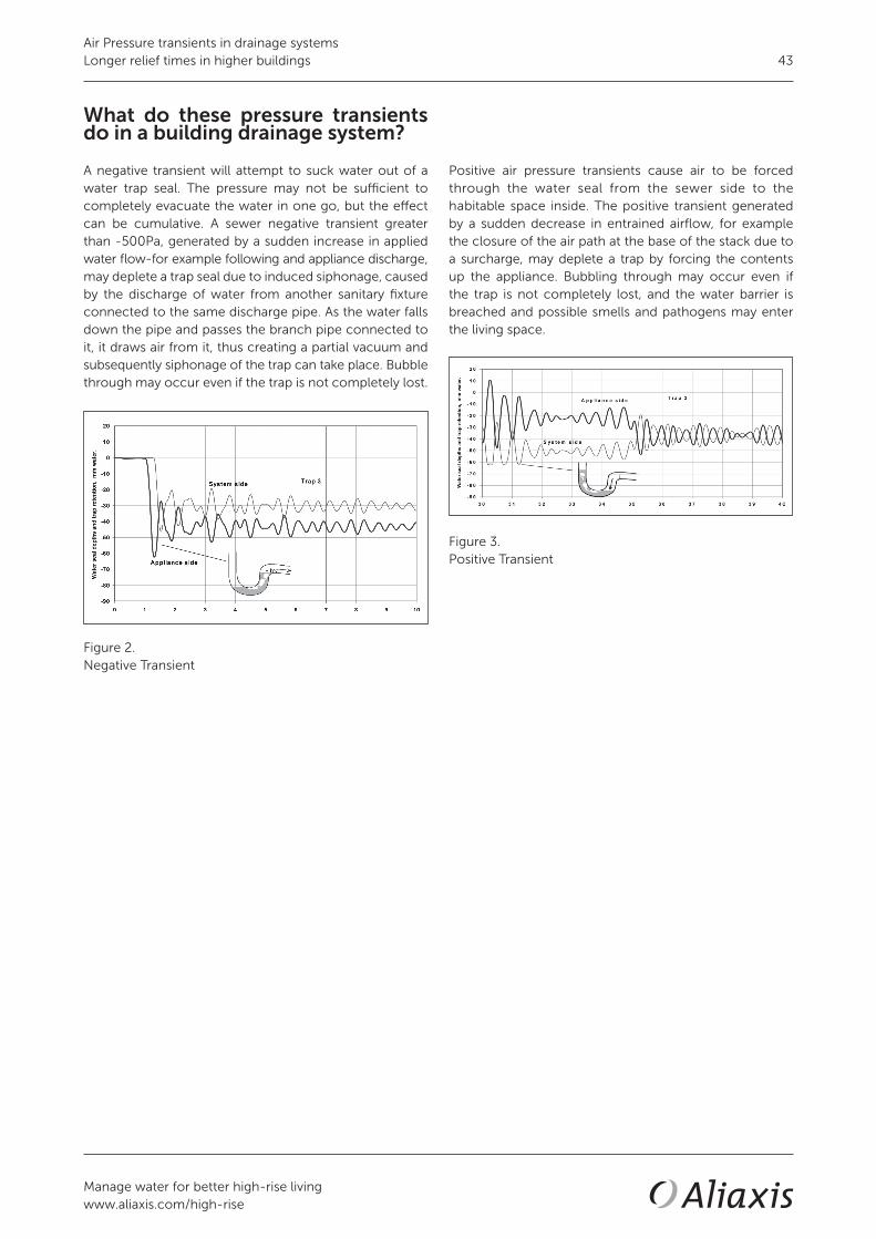
Positive air pressure transients cause air to be forced through the water seal from the sewer side to the habitable space inside. The positive transient generated by a sudden decrease in entrained airflow, for example the closure of the air path at the base of the stack due to a surcharge, may deplete a trap by forcing the contents up the appliance. Bubbling through may occur even if the trap is not completely lost, and the water barrier is breached and possible smells and pathogens may enter the living space.
Figure 3.Positive Transient
What do these pressure transients do in a building drainage system?
A negative transient will attempt to suck water out of a water trap seal. The pressure may not be sufficient to completely evacuate the water in one go, but the effect can be cumulative. A sewer negative transient greater than -500Pa, generated by a sudden increase in applied water flow-for example following and appliance discharge, may deplete a trap seal due to induced siphonage, caused by the discharge of water from another sanitary fixture connected to the same discharge pipe. As the water falls down the pipe and passes the branch pipe connected to it, it draws air from it, thus creating a partial vacuum and subsequently siphonage of the trap can take place. Bubble through may occur even if the trap is not completely lost.
Figure 2.Negative Transient
Air Pressure transients in drainage systemsLonger relief times in higher buildings

Manage water for better high-rise livingwww.aliaxis.com/high-rise
44
Conclusion
The need to communicate an increase or decrease in the air flow and the finite time that this takes is central to the requirements of providing a safely engineered drainage system. The absolute key to maintaining a state of equilibrium in a drainage system is to provide pressure relief as close to the source of an event as possible, in high-rise and more complex buildings the source of relief is a greater distance so the longer the time it takes for the system to respond. To limit the effect of these transients in taller buildings active drainage ventilation solution will reduce the response times or alternatively solution is to control the flow so that the air paths and the pressures generated in the system do not reach levels that the water trap seals are lost, stack-aerators control the flow and prevent the closure of the air paths in the system.
Steve WhiteTechnical Director DWVAliaxis High-Rise Building Solutions
MSc (Ir.) Marc Buitenhuis MTDResearch Engineer Hydro-DynamicsAliaxis
09
/17/
126
1. Jack L.B., (2000). Developments in the definition of fluid traction forces within building drainage vent systems’, Building Services Engineering Research & Technology, Vol 21, No 4,
2. Swaffield, J.A.,Campbell, D.P., Gormley, M. (2005) ‘Pressure transient control: Part II—simulation and design of a positive surge protection device for building drainage networks’ Building Services Engineering Research and Technology
Read more technical papers related to this subject
• Design - Limiting roof penetrations in high-rise buildings• Design - Offsets in Building Drainage systems• Design - Vertical Flow in High-rise Drainage Systems• Relevance - Above ground drainage and vent systems• Relevance - Purpose of a High-Rise Drainage and Ventilation system • Relevance - Requirements for a well-designed high-rise drainage system• Relevance - Water Trap Seal• Research - Current venting diameters for high-rise drainage ventilation • Research - National Lift Tower• Research - What happens at the base of the stack• Solution - Air Admittance Valves (AAV)• Solution - Stack-aerator system principles• Solution - Active Ventilation Single Stack Drainage
Air Pressure transients in drainage systemsLonger relief times in higher buildings

High-rise building solutions
Research Relevance Design Solutions Materials Installation Terminology Standards
Technical paper
High-rise design practice and codes for drainage and ventilation systems
In line with research or not?
Steve White
Technical Director DWVAliaxis High-Rise Building SolutionsUnited Kingdom10/2017
Abstract
Engineers around the world, all have the same issues when it comes to designing high-rise and drainage ventilation systems, what codes to follow and do they work for the building? At present the standards they have to follow contradict current research, in regards to the correct venting required to ensure that the water traps seals are protected from transient pressure.
Context of this paper
This technical paper is part of a library op technical papers. Refer to the below overview of all our technical papers and click on the title for a digital link.

Manage water for better high-rise livingwww.aliaxis.com/high-rise
46
Introduction
The most common standards used to design high-rise drainage systems around the world are: • EN 12056-2: The design guide for Europe, also
commonly used in the Middle East and Asia.• AS/NZS 3500-2003: Used in Australia, New Zealand,
also in the Middle East and Asia.• BS 5572: Can still be found in being used in Asia and
the Middle East, despite its withdrawal as a British Standard in 2000 when it was replaced in the building regulations by the EN 12056-2.
• International Plumbing Code: A private code for the USA adopted by 30 states.
• Unified Plumbing Code: A private code for USA adopted by 12 states in the USA and also recently adopted by the Indian Plumbing Association as the IUPC. The UPC is also followed in Vietnam and the Philippines.
There are a number of other plumbing standards but from experience in the market place these listed seem to be the main standards that are adopted. Each of these standards recommends passive venting solutions (vent pipes) with smaller vent diameters or reduced loadings with increased vent lengths for taller buildings. The data for the guidance is based on research carried out form the 1930-1970, when the world was building smaller buildings than we are today.
High-rise design practice and codes for drainage and ventilation systemsIn line with research or not?

Manage water for better high-rise livingwww.aliaxis.com/high-rise
47
EN 12056-2 drainage ventingrequirements
It can be seen by the recommendations of the standard show in the below Tables 1 to 3 that engineers have been given the vent requirements for the size of pipes that they use in their system.
Table 1.Branch loadings with required branch and vent sizing
Table 2.Secondary stack and vent requirements commonly used in high-rise designs
Table 3.Limitations
The EN 12056 was developed for buildings up to 20 floors, and was based from existing European codes, from the research carried out by CEN in the 1950-1960, although there is no maximum height specified in the standard. Buildings in the UK and across Europe are commonly being built well above twenty floors, especially in main city areas.
It can be seen in Table 3, that if a 200 DN stack is being used, the secondary vent should be sized at 100 DN; 50% smaller than the waste carrying stack. It can also be seen that a 150 DN pipe (which is the most commonly used pipe used in high-rise buildings) requires a secondary vent of 80 DN; 47% smaller than the waste carrying pipe.
High-rise design practice and codes for drainage and ventilation systemsIn line with research or not?

Manage water for better high-rise livingwww.aliaxis.com/high-rise
48
AU/NZS 3500-2003 drainage vents requirements
The AU/NZS 3500 is a standard that must be followed; any design outside the scope of the standard must gain alternative solution approval from the city or state where the project is based.
Table 4 gives the maximum branch vent sizing required and for 50 mm to 100 mm traps the largest branch vent required by the code is 40 mm DN.
Table 5 gives the sizing requirement for the relief/ stack vents for the size of stacks that they are installed upon. It indicates for the size the stack the maximum FU as well as the required vent size and the maximum height allo- wed for the size of the vents.
Table 4.Branch vent sizing
Table 5.Size of relief vents and stack vents
An example project of a 254 meter building (86 floors) was designed using table 5 with 225 DN stacks. The FU rating is between 1700 FU (Qww 15.8l/s) to 7000 FU (Qww 32.2l/s) so the maximum developed vent length allowed in meters would be 62 meters with 150DN vent the largest vent size in the standard.
15 FU = 1.5 l/sec of flow rate.
This project of 254 meters, high-rise, would falls outside the scope of the standard according to table 5 if the 225 stack was used.
To meet the requirement of the standard the design would have to use smaller stack diameters for example:
125DN stack with a FU 300 (Qww 6.6l/s) with a 125DN vent.
Or
150DN stack with a FU 1300 (Qww 13.8l/s) with a 150 DN vent.
Both of the solutions would require more stacks to be installed into the project, taking up more space.
Even if the load is reduced, and the correct vent stack is used, the requirement in table 4 for the branch vent to be a maximum size of 40 DN would add resistance of this small pipe diameter and can lead to restriction of communication for pressure relief of the branches in high-rise buildings and thus lead to the possibility that the traps seals could be depleted due to induced siphonage.
High-rise design practice and codes for drainage and ventilation systemsIn line with research or not?

Manage water for better high-rise livingwww.aliaxis.com/high-rise
49
Main USA codes
The IPC is the most commonly adopted code within the USA followed by the UPC and is more of a rule book than a code or guide which is enforced by local inspectors. This raises separate issues as they generally have good interpretation and understanding of the code book, but have not undergone degree-level engineering required to design drainage systems in high-rise buildings. This leads to two issues: Firstly, the inspector becomes the dominant factor in the design of the system and if the building system is not to the code it will not be accepted (red flagged); and secondly, the design engineer becomes accustomed to designing to the code and can therefore forget the principles of engineering and understanding of the require-ments of the system.
If the code is wrong then the design is wrong. The question that needs to be addressed is whether the code is suitable for high-rise buildings.
Section 91.16 of the code relating to vent pipe sizing states: “Size of stack vents and vent stacks. The minimum required diameter of stack vents and vent stacks shall be determined from the developed length and the total drainage fixture units connected thereto in accordance with [Table 6], but in no case shall the diameter be less than one-half the diameter of the drain served for less than 1 ¼ inches (32 mm).”
Table 6.Size guide for IPC code
Table 7 illustrates the sizing of vents within the Uniform Plumbing Code.
Table 7.Sizing of vents from the UPC
If a standard high-rise design was used, 150 DN stack with 100 DN vent pipes, then the standard would be suitable for a 40 floor building. If the building has to be taller, they would have to increase the size of the stack as well as the size of the vents, even though the DFU loading was not increased. This can lead to oversized systems that may not be required and will take up more space within the building.
International code discussion
Tables 2, 3, 5 and 7 provide the main guidance available to engineers for their system designs. The guidelines or rules in these standards allow for taller buildings but only by reducing the loading or oversizing the system.
The research carried out at Heriot-Watt University, as well as other leading technical institutions and manufacturers with high-rise testing facilities, can and should assist code and standards originations in providing technical solutions for the design engineers to design systems that are safe and practical for the needs of high-rise buildings.
Introducing a new concept that are not part of the guide tables within the standards, that challenges the guide sizing and system designs that are available can only be achieved by having the latest research that meets the requirements of high-rise drainage systems.
High-rise design practice and codes for drainage and ventilation systemsIn line with research or not?

Manage water for better high-rise livingwww.aliaxis.com/high-rise
50
Conclusion
Over the last decade there has been an unprecedented increase in high-rise buildings around the world requiring engineering disciplines to meet the requirements in structural and system operation to these types of buildings. In regards to drainage, has this been met? This paper highlighted and asked the question if the standards and codes meet these demands for high-rise building designs. The leading research carried by Heriot-Watt University has demonstrated that the current standard and code requirements may not be sufficient in their recommendations to provide effective guidance to the engineering community to design workable safe systems. There are many cases where the recommendations in the standards have been modified by the engineers as they have experienced problems in prerious designs and wish to engineer out problems in future buildings. Sometimes this has been restricted by the regulators within different states due to their insistence that the code is followed as it is written, and therefore engineers are unwilling to deviate from this even if it means that the system may become susceptible to failure. Drainage is a relatively easy system to understand for any type of building design: Hydraulic loading for the sizing of pipes; and a venting system that keeps the pressures below +- 400Pa throughout the system. If the pressures are kept well below this, in the region of +- 200Pa, there is less stress placed on the trap seals within the system. With a passive system there is a single limitation, that being the only way to relieve the transient pressures through a network of ventilation pipes that terminate at the top of the building. Using systems such as active drainage ventilation or stack-aerators manage the air pressures within the drainage system, so the limitations on the vent pipe lengths is removed for tall buildings.
Steve WhiteTechnical Director DWVAliaxis High-Rise Building Solutions
MSc (Ir.) Marc Buitenhuis MTDResearch Engineer Hydro-DynamicsAliaxis
09
/17/
116
1. BSI British Standard Institution (2004). European Standard BS EN 12056-2:2000 2. International Code Council (2003). US Standard International Plumbing Code-IPC 3. International Association of Plumbing and Mechanical Officials (2003). US Standard Uniformed Plumbing Code-UPC 4. Standard Australia (2003). Australian Standard AS/NZS 3500.2-2003 5. Wang Xuejiao (2007). Study on flux capacity of single stack drainage system: Non-Roof, Penetration Self Circulating
Drain System Stack Tongji University6. Prof J.A. Swaffield, Dr L.B. Jack, Dr D.P. Campbell (2006). The Active Control and Suppression of Air Pressure
Transients within the Building Drainage System. Studor commissioned report.7. Prof J.A. Swaffield, Dr M. Gormley (2006). Comparisons of Venting Options under positive and negative pressure
transients for a 50 storey building using numerical model AIRNET. Studor commissioned report.8. Swaffield JA (2010). Transient Airflow in Building Drainage Systems, published by Spon Press
Read more technical papers related to this subject
• Relevance - Above ground drainage and vent systems• Relevance - Air Pressure transients in drainage systems• Relevance - Purpose of a High-Rise Drainage and Ventilation system• Relevance - Requirements for a well-designed high-rise drainage system• Relevance - Water Trap Seal• Research - Current venting diameters for high-rise drainage ventilation• Research - National Lift Tower• Research - What happens at the base of the stack
High-rise design practice and codes for drainage and ventilation systemsIn line with research or not?

High-rise building solutions
Research Relevance Design Solutions Materials Installation Terminology Standards
Technical paper
Purpose of a High-Rise Drainage andVentilation system
The fundamentals
Steve White
Technical Director DWVAliaxis High-Rise Building SolutionsUnited Kingdom10/2017
Abstract
The fundamental purpose of a high-rise drainage system is the removal of fluid and solid waste to the sewer while protecting the inhabitants of the building from cross contamination from sewer gases and pathogens from within the drainage system by ensuring water trap seals are maintained. The system should require minimal maintenance, should be as quiet as possible so as not to disturb the occupants from noise from discharges above and below them. Ideally the system should only require minimal resources to do this, in the terms of water usage as well as materials, to achieve the aim of sustainable (green buildings). Single stack drainage systems such stack-aerators or active drainage ventilation achieve this.
Context of this paper
This technical paper is part of a library op technical papers. Refer to the below overview of all our technical papers and click on the title for a digital link.

Manage water for better high-rise livingwww.aliaxis.com/high-rise
52
Introduction
Since the late 1700s water trap seals were seen as a solution, using a U-tube as a solution that would separate the drainage system from the building interior.
The industrial revolution in the UK from 1760-1840 lead to the first mass migration and urbanisation. The mass of people overcrowding living in towns and cities lead to increase in disease and deaths to which the poor sanitation of these population centres played a major part.
In the late 1800s this lead to the foundation of what we have as today’sdrainage and ventilation systems, using water to remove the waste water and solids and the use of water trap seals to protect the occupants of the buildings reducing the infections and deaths with good sanitation. In the 1950 -1960 further research was carried out to give the bases for the national codes in use today, but based on steady state discharge and for low rise buildings.
Today in the world we are living in a modern urbanisation with predictions that 80% of the world’s population will become urbanised by 2050 and to meet this many cities are building high-rise buildings.
To ensure that with this new urbanization and that the mistakes of the past do not happen again, the high-rise drainage and ventilation must be designed so that the waste and solids are moved to the sewer and that the water trap seals are maintained to protect from cross-contamination.
The outbreak of the SARS virus at Amoy Gardens in Hong Kong back in 2003, high-lights the risk when the system fails, with 53 deaths and the forensic investigation proving that the infection was transmitted through the depleted water trap seals, poor design and lack of maintenance.
Requirements
The requirements of the drainage system have not changed from what was required back in the late 1800s, the core principles are the same these being:
• Remove waste from the habitable space via the sanitary appliance
• Retain a physical protection between the drainage pipework and the habitable space
In modern high-rise drainage and ventilation systems with with high-occupancy and increased loadings and longer pipe lengths involved in building the 30, 50 and 100+ storey tall buildings, the requirement to ensure that not only the waste is removed quickly to the sewer but also that the habitable space and the occupants in the building are protected from cross contamination by ensuring good design principles, so that the water traps seals are maintained.
Through research institutes such as Heriot Watt University, Drainage Research Group, evaluation of current national guidance has been undertaken, focusing on high-rise buil-ding drainage recommendation using simulation tools such as AIRNET as well as empirical testing. One of its key findings is that national code guidances undersize the venting requi-rements as well as unsteady flows condition for tall buildings.
In partnership with manufacturers and research institutes, together they developed solutions to meet the require-ments of high-rise drainage systems. Guidance and data is available for national code bodies to re-evaluate their guidance for high-rise drainage and ventilation.
Testing on high-rise drainage test facilities, such as the NTL test tower in the UK and the HDEC in Holland ensure validation of the research as well as ensuring that products developed meet the demand and functionality required for tall buildings. They are also used to support the industry through live interactive technical demonstrations; seeing the operation of how a high-rise drainage system works “seeing is believing”.
Figure 1.Top 10 tallest high-rise buildings
Purpose of a High-Rise Drainage and Ventilation systemThe fundamentals

Manage water for better high-rise livingwww.aliaxis.com/high-rise
53
Stack-aerators solution
• Slows the downward flow of water to prevent the for-mation of hydraulic plugs.
• Prevents waste water from branch lines mixing with other waste water until below the junction point.
• Has only one outlet pipe, replacing the need for a conventional two-pipe fully-vented or a fully ventila-ted modified stack system for multi-storey buildings.
• Provides significant cost savings through reduced pipe work and associated construction increasing flexibility for architects and designers of multi-storey buildings
• A single pipe stack, eliminating all additional pipe work required for relief venting
• Increased design flexibility with longer unvented branch drains, to a maximum of up to 10 metres • Space-saving through the elimination of bulkheads • Installation and construction cost savings through the elimination of venting pipe work.
Figure 3.Stack-aerator solution
Single stack solutions
Not only have these systems been developed for high-rise buildings, the research and testing has and is focused to meet the demands and operation for tall buildings, not only based on current loadings guidance, but focusing on water saving appliance, where less water is required to carry the waste and solids to the sewer and the impact on the function of the system.
They also meet the requirement of modern buildings to be sustainable, helping these building reach the green sustainability approvals, by removing the vent pipes from the building, saving in tall buildings 20-40 Km of pipe work that was required to vent the system.
They are tested to ensure the protection of the water trap seals barrier is maintained when air pressure transients are generated by the unsteady flow conditions, or in the case of stack attractors ensure that the pressure fluctua-tions are kept to a minimum.
Active Drainage Ventilation solution
With substantial research and completed projects, Active Drainage Ventilation, utilizing air admittance valves and P.A.P.A. provides:• Reduced system complexity• Reduced time of installation and labour• Reduced material used in the system, bringing sustai-
nability to the design• Increased predictability of the system operation • Ability to place suppression between transient source
and appliances’ trap seals to be protected • Interception of transients prior to propagation throug-
hout the network and impact on all connected appliance trap seals
• Single stack system• Suitable for buildings of over 100 floors• System pressures kept in the region +-100Pa, well
below +-400Pa that affect trap seals in the system
Figure 2.Active drainage ventilation solution
Purpose of a High-Rise Drainage and Ventilation systemThe fundamentals

Manage water for better high-rise livingwww.aliaxis.com/high-rise
54
Conclusion
The purpose of high-rise drainage and ventilation remains the same as low –rise drainage and ventilation, namely to remove the waste from the building to the sewer and ensure that the occupancies of the building are protected from cross-commination from the gases and pathogens from within the system.
Current national code guidance was based on steady state, low rise testing. To ensure that the drainage system for high-rise buildings is fit for purpose, the guidance within the codes needs to be revaluated and tested. Active drainage ventilation and stack-aerators are two systems that have been tested and researched for use in high-rise buildings and ensure that the system are fit for purpose.
Steve WhiteTechnical Director DWVAliaxis High-Rise Building Solutions
MSc (Ir.) Marc Buitenhuis MTDResearch Engineer Hydro-DynamicsAliaxis
19/1
7/11
9
1. London, 2000 Swaffield, J. (2010) Transient airflow in building drainage systems, Oxon: Spon Press
2. CTBUH Tall Building Database | The Skyscraper Centre www.skyscrapercenter.com.
3. Swaffield J. A. and Galowin L.S., (1992) ‘The engineered design of building drainage systems’, Ashgate Publishing Limited, England
Read more technical papers related to this subject
• Relevance - Above ground drainage and vent systems• Relevance - Air Pressure transients in drainage systems• Relevance - Water Trap Seal• Research - Current venting diameters for high-rise drainage ventilation• Research - National Lift Tower
Purpose of a High-Rise Drainage and Ventilation systemThe fundamentals

High-rise building solutions
Research Relevance Design Solutions Materials Installation Terminology Standards
Technical paper
Requirements for a well-designedhigh-rise drainage system
Crucial in the safety and comfort forinhabitants
Steve White
Technical Director DWVAliaxis High-Rise Building SolutionsUnited Kingdom10/2017
Abstract
Put simply, the main requirement of a well-designed high-rise drainage system is that it should operate without the user being aware of its existence, and to protect the occupants of the building from the sewer gases and pathogens within the drainage system.
Context of this paper
This technical paper is part of a library op technical papers. Refer to the below overview of all our technical papers and click on the title for a digital link.

Manage water for better high-rise livingwww.aliaxis.com/high-rise
56
Introduction
To most people the building drainage system lurking beneath their pristine ceramic and stainless steel appliances presents a mystery beyond their usual ‘need to know’. How their sink full of soapy water gets from their newly refurbished kitchen island to the municipal treatment plant is of little or no interest, and, likewise, few people ponder the similar journey from the WC, bath or bidet in the bathroom; until that is, they are suddenly faced with a foul smell from ‘somewhere down there’ or are met by a filling WC bowl which keeps on filling and pours onto the new floor covering. The mystery surrounding the drainage system suddenly deepens on the presentation of an unfeasibly costly repair bill. In fact the heart of any building system are the services, which are only a small part of the construction investment. By contrast, the comfort of a high-rise building highly depends on the correct functioning of the services, especially the drainage system that protects the inhabitants against bad smells and pathogens present in the sewer.
In truth there are few mysteries about the operation of a building drainage system. The underlying principles governing the flows of all fluids (water and air) have been well described and indeed applied to the building drainage system for both design (making the system work) and forensic analysis (finding out why it didn’t work) for many years.
This is a crucial point because, building drains carry unsteady flows which mean that they are rapidly changing and cannot be analyzed using simple calculations based on steady, unchanging flows, flow principles. Understanding these principles and requirements for high-rise drainage designs leads to the goal of invisible system for the occupants.
Requirements of the system
The following requirements are essential in achieving a safe, usable and reliable drainage system for high-rise buildings;• The system should remove all waste as quickly as
possible• Long horizontal pipe runs must be self-cleansing • There must be minimal loss of water trap seal to
ensure there is a barrier for the ingress of sewer gases• Minimal noise from the system• Ease of maintenance • Durable and proven solutions
Requirements for a well-designed high-rise drainage system Crucial in the safety and comfort for inhabitants

Manage water for better high-rise livingwww.aliaxis.com/high-rise
57
Solution
As with most fields of engineering, sanitary equipment and techniques have benefited from scientific and engineering research, manufacture innovation and product development, which together has improved understanding of system operation and helped develop new innovate and cost-effective ways of achieving the goal of safe, reliable drainage systems with no increase in health risk.
In particular the active drainage ventilation solution for protecting water traps seals, stack-aerator solutions that control the flows, both these options are to provide single stack drainage systems solutions and have been designed for use in high-rise buildings from their initial concept.
Testing of these systems as well as conventional pipe systems as recommend by the codes is ongoing and the ability to validate their performance at the Hydro-Dynamics Experience Centre (HDEC) and the National Lift Tower (NLT) (two dedicated drainage test towers) and working with leading research institutions - for example, the Drainage Research Group at Heriot Watt University - will allow designers and code regulators to give guidance and solution for meeting the requirements for high-rise drainage systems.
Codes and Regulations
Code regulations were essentially designed in order to ensure that installations meet these requirements, and to protect inhabitants against any possible health risks from contact with contaminated fecal material, sewer gases and pathogens.
In developed industrialized countries the majority of installations meet these standards and the health risks from drainage systems are still very low. The basis for this has been achieved on data generated for low rise buildings based on the research carried out in the 1950s and 1960s by CEN.
With modern day high-rise buildings and urbanization the usage patterns and the density of occupants, it is recom-mended that the codes and regulations be revisited to ensure the guidance meets the requirements in modern high-rise buildings.
Figure 1.National Lift Tower
Figure 2.Hydro-Dynamics Experience Centre
Requirements for a well-designed high-rise drainage system Crucial in the safety and comfort for inhabitants

Manage water for better high-rise livingwww.aliaxis.com/high-rise
58
Conclusion
It is not unreasonable for occupiers living and working in high-rise buildings to expect that their drainage system works and has no issues for the life of the system. The system requirements to achieve this are well known. Given that new buildings are being built ever taller and are out of scope of current guidance, manufactures and research work together to provide solutions and data to allow regulators the information so that all high-rise buildings meet the requirement for high-rise drainage systems.
Steve WhiteTechnical Director DWVAliaxis High-Rise Building Solutions
MSc (Ir.) Marc Buitenhuis MTDResearch Engineer Hydro-DynamicsAliaxis
Read more technical papers related to this subject
• Design - Vertical Flow in High-rise Drainage Systems• Relevance - Above ground drainage and vent systems• Relevance - Air Pressure transients in drainage systems• Relevance - High-rise design practice and codes• Relevance - Purpose of a High-Rise Drainage and Ventilation system• Relevance - Water Trap Seal• Research - Current venting diameters for high-rise drainage ventilation• Research - What happens at the base of the stack• Solution - Air Admittance Valves (AAV)• Solution - Active Ventilation Single Stack Drainage
09
/17/
115
Requirements for a well-designed high-rise drainage system Crucial in the safety and comfort for inhabitants

High-rise building solutions
Research Relevance Design Solutions Materials Installation Terminology Standards
Technical paper
Water Trap Seal
How it keeps inhabitants safe from sewer pathogens
Steve White
Technical Director DWVAliaxis High-Rise Building SolutionsUnited Kingdom10/2017
Context of this paper
This technical paper is part of a library op technical papers. Refer to the below overview of all our technical papers and click on the title for a digital link.
Abstract
The appliance water trap seal was invented in 1770 by Alexander Cummings and was incorporated into Victorian drainage designs to reduce a source of infection spread and a desire to eliminate odour. The simple introduction of a U-tube filled with water capable, due to a water column height designed to exceed any applied air pressure from the system, of preventing any odours within the system from penetrating into habitable space, was a major advance that remains the first line of defence against cross-contamination. It has remained an essential feature of all building drainage design since the early 19th century. The depth of the water seal, 50 or 75 mm, is sufficient if properly retained to prevent any passage of air into habitable space from the drainage network. Understanding what leads to the depletion of water traps seals and the barrier that they provide is important for public health. In high-rise buildings even more so after the SARS outbreak in Hong Kong at the Amoy Gardens in 2003 where the infection spread identified by WHO (2003) was exacerbated by poor drainage design and trap seal depilation.

Manage water for better high-rise livingwww.aliaxis.com/high-rise
60
Traps
Traps should be designed so that deposits such as hair, soap and food waste for example do not accumulate in the trap after a discharge through the trap.
The internal surface of the trap should be smooth throughout. All traps should be accessible and should be self-cleaning. There should be no more than one trap on the discharger pipework from any appliance, as the velocity of flow through the gravity generated by the slop will be reduced through a second trap leading to accumulation of solids and the reduction of the water trap seal. a) WC traps typically 50 mm in depth b) Tubular traps typically P or S traps with depths of 50 mm or 75 mm c) Bottle traps with depths of 75 mm d) Anti-vacuum traps with depths of 50 mm or 75 mm with an integrated air admittance valve e) Resealing trap with depths of 75 mm.
Figure 2.Different water traps
Figure 1.Water seal behaviour
Introduction
The complex building drainage and vent systems in large buildings will entrain airflows at rates many times the driving water flow rate and hence the mechanism by which air entrainment occurs, and the effect of changes in this water flow, determining air entrainment, become vital to an understanding of the pressure regime within the system and the impact that changes in pressure have on the survivability of the appliance traps seals that provide the protective barrier that minimises the risks of cross-contamination between the drainage network and habitable space. Air pressure transients in excess of the depth of the water trap seal will deplete the trap seal. In a high-rise building the trap with the least seal depth will be the trap at most risk of being lost.
Water Trap SealHow it keeps inhabitants safe from sewer pathogens 60

Manage water for better high-rise livingwww.aliaxis.com/high-rise
61
Water trap seal depletion
Figure 3.What depletes the water seal in a trap
Evaporation, (a), is caused by the local ambient conditions. The routine installation of floor drains in plant rooms is now not advisable as the modes of floor cleansing no longer provide the water needed to ‘top up’ the trap.
Self-siphonage, (b), is caused by the appliance discharge having sufficient momentum to carry the trap seal out into the connected branch. Wise and Croft (1954) recommended either increasing the branch diameter downstream of the trap, this is now standard practice, or providing a local vent relief by a connection to the vent stack. In more recent times this recommendation may be met by providing a local air admittance valve.
Figure 4.Self siphonage
Induced siphonage, (c), is due to the air pressure transients propagating within the drainage network and may be avoided by local venting or careful selection of the branch diameter and slope in single stack applications.
Figure 5.
Back pressure, (d), is due to positive air pressure transients generated within the system either by system surcharge, at the stack base or at any stack offset, or by positive pressures entering the network from the sewer, again possibly due to a remote system surcharge or pump operation. If the positive air pressure transient is in excess of 50 mm-100 mm Wg the traps will have cross-contamination to the trap blowing out of the appliance.
Figure 6.
The solution is to vent the branch leading to the trap or to install a P.A.P.A. locally to absorb the incoming positive transient.
Wind-driven oscillation (e) of the trap seal may occur due to the wind shear over the roof level stack termination and may lead to trap seal loss due to the sinusoidal wave of the wind. If the air pressure transient is in excess of 50 mmWg trap seal loss may occur. Typical wind gusting at 35 Kmh will generate a harmful transient.
Water Trap SealHow it keeps inhabitants safe from sewer pathogens

Manage water for better high-rise livingwww.aliaxis.com/high-rise
62
Conclusion
The the majority of trap seal depletion is due to air pressure transients, 2l/s of flow rate can generate an air pressure transient of 50 mm Wg and 50 mm depth trap seals are at risk. An air pressure transient of 75 mm Wg will lead to loss of these traps. To prevent the loss of the trap seals the system should be designed so that the system pressures do not exceed 40 mm Wg. This can be achieved, by using stack-aerators or active drainage ventilation to keep the whole system below -+15 mm Wg and place no stress on the water trap seals, so that the barrier in maintained and the risk of cross-contamination can be avoided.
Steve WhiteTechnical Director DWVAliaxis High-Rise Building Solutions
MSc (Ir.) Marc Buitenhuis MTDResearch Engineer Hydro-DynamicsAliaxis
09
/17/
118
1. EN 12056:2000 ‘Gravity Drainage Systems inside buildings Part 2: Sanitary Pipework, layout and calculations’, British Standards Institute, London
2. Swaffield, J.A.,Campbell, D.P. , Gormley, M. (2005) ‘Pressure transient control: Part I - criteria for transient analysis and control’ Building Services Engineering Research and Technology, Volume 26
3. Wise, A.F.E (1957) ‘Drainage pipework in buildings: Hydraulic design and performance’ HMSO, London
4. Swaffield J.A & Boldy A.P (1993) 1993, ‘Pressure surge in pipe and duct systems’, Avebury Technical, England
5. Swaffield J. A. and Galowin L.S., (1992) ‘The engineered design of building drainage systems’, Ashgate Publishing Limited, England
6. Swaffield JA (2010). Transient Airflow in Building Drainage Systems, published by Spon Press
Read more technical papers related to this subject
• Relevance - Above ground drainage and vent systems• Relevance - Air Pressure transients in drainage systems• Relevance - High-rise design practice and codes• Relevance - Purpose of a High-Rise Drainage and Ventilation system• Relevance - Requirements for a well-designed high-rise drainage system• Research - Current venting diameters for high-rise drainage ventilation• Research - National Lift Tower• Research - What happens at the base of the stack• Solution - Air Admittance Valves (AAV)• Solution - Active Ventilation Single Stack Drainage
Water Trap SealHow it keeps inhabitants safe from sewer pathogens

Design• Limiting roof penetrations in high-rise buildings
• Offsets in building drainage systems
• Vertical flow in high-rise drainage systems
Manage water for better high-rise livingwww.aliaxis.com/high-rise
63


High-rise building solutions
Research Relevance Design Solutions Materials Installation Terminology Standards
Technical paper
Limiting roof penetrationsin high-rise buildings
How to supply enough airto the drainage system
Steve White
Technical Director DWVAliaxis High-Rise Building SolutionsUnited Kingdom10/2017
Context of this paper
This technical paper is part of a library op technical papers. Refer to the below overview of all our technical papers and click on the title for a digital link.
Abstract
A building cannot function without a drainage system; it is a fundamental requirement, removing drainage waste and protecting the occupants from gases and pathogens. The drainage system requires air to balance the pressures, pre-venting water trap seals from being depleted. The method of bringing air into the system directly impacts the architec-ture of a building, providing a challenge for Mechanical, Electrical and Plumbing (MEP) design engineers to find ways of providing air for the drainage system without compromising the design aesthetically.Bringing air into the drainage system has traditionally been achieved by the use of stack-vent pipes running from the highest branch connection of the stack to the top, protruding through the roof of the building. This is of particular con-cern in the design of tall buildings where, for health and aesthetic reasons, the large number of these unsightly pipes cannot be located near roof top pools, podiums, air handling units, etc. To meet the architectural design of a building, MEPs often seek a solution to limit the roof penetrations by using linked vents and side venting. This paper addresses the limitations and risks of these methods and provides a solution using active drainage ventilation, which allows a building to fully function with limited drainage vents to atmosphere and removes any limitation on architectural design

Manage water for better high-rise livingwww.aliaxis.com/high-rise
66
1. Introduction
All buildings are different, and developers and architects often wish their buildings to stand out aesthetically. While this is important for the overall look of the building it also means that the developer can charge more for the space. Space is a premium commodity. Building services engineers (BSE) and Mechanical, Electrical and Plumbing Engineers (MEP) are required to make their designs fit the ever decreasing allocation of space. Each engineering discipline provides solutions; this paper addresses the drainage ventilation, and the solution that public health and MEP engineers are using to limit the unsightly drainage vents that limit the aesthetics of the building. It is worth noting at this point that architects’ drawings and models never show vent pipes as this is not part of their vision for the building (see Figure 1.)
Figure 1.Typical architect model without drainage vent pipes
The main methodology that the public health engineers and MEPs currently use to hide the vent pipes involve linking the stacks at the top of the building so that three or more stacks have only one roof penetrations to atmosphere, as shown in Figure 2. The question is: does the solution work to protect the water traps seals in the building?
Figure 2Linked Vents
Limiting roof penetrations in high-rise buildingsHow to supply enough air to the drainage system

Manage water for better high-rise livingwww.aliaxis.com/high-rise
67
2. Linked Vents
In practice every stack should be connected to atmosphere if passive drainage venting is used, the principle being that if there are discharges within the stack, the vent at the top of the stack will provide air through the drainage vent pipe network to relieve the negative transients generated in the system. The same vent pipe network is also per-ceived to provide relief paths for the positive transients generated within the drainage network to the vent at the top of the stack, however this is a less effective means of pressure surge alleviation.
The sizing and the efficiency of passive drainage venting has been discussed many times at CIB W062, the world’s leading research forum in water supply and drainage. The use of computer techniques to predict the generation, propagation and alleviation of air pressure transients in buildings has been well discussed previously and the computer program AIRNET has been instrumental in the analysis and performance of passive venting and the correct sizing that is required for it to work efficiently for tall buildings. A full analysis of the problem is given by Swaffield (2010)(4), and this area of concern can be found in Chapter 5.7. of the Transient Airflow in Building Drainage Systems, published by Spon Press.
It should be remembered that all the research on passive drainage venting in the past and which has gone on to inform codes and standards worldwide has been based on the assumption that each stack is vented individually to atmosphere. Within plumbing drainage codes them-selves, it is also assumed that each stack is individually vented, although there has been room in some codes to interpret that as long as the stacks are connected to atmosphere it will meet the requirement of the codes.
Engineers are using the interpretation that as long as the stacks are connected to atmosphere they can provide a cross link to connect a number of stacks to one open vent to meet the architectural requirements of the building.
To achieve this many engineers specify that the link vent used at the top of the stack is larger than the stacks in diameter. It is very typical for three to ten 100DN sized stacks, to have a 150DN linked vent running at the top of the building. In theory this will provide more air, however this arrangement interlinks all these stacks at the top and so facilitates the unwanted transmission of pressure transients from one stack to another.
This design principle is becoming more popular over the last five years but there is no evidence that it will work using passive venting principles due to the time depen-dency of the vent system to respond to the pressure regime within the system
Limiting roof penetrations in high-rise buildingsHow to supply enough air to the drainage system

Manage water for better high-rise livingwww.aliaxis.com/high-rise
68
2.1 Design example
A 24 floor building was assessed by numerical modelling to see how it performed when linked vents were used. The system is designed to EN12056 and simulations were carried out using AIRNET ( Swaffield, 2010)
Figure 3.Partial schematic of the building drainage design showing linked vents at the top
It can be seen from Figure 3 that in this building 10 100mm stacks have been cross linked using a 150mm stack-vent to provide a single penetration through the roof.
Limiting roof penetrations in high-rise buildingsHow to supply enough air to the drainage system

Manage water for better high-rise livingwww.aliaxis.com/high-rise
69
An AIRNET analysis of this building was carried out to see what would happen if the system was loaded to its design capacity. The building was designed to EN12056:2000 and so the maximum loading would be 5.2 l/s using swept entry T-branches. If one of these stacks was loaded to its maximum and there was some other activity in other stacks, would the single vent pipe be capable of proving the complex air requirements of the system?
The best way to assess the issue is to look at water trap seal retention in parts of the building which might be vulnerable under heavy usage load conditions.
Three loading profiles were used in the simulations: 5.2 l/s peak, 1.5 l/s peak, 2.5l/s peak and 1 l/s peak. This is shown in Figure 4. The flow rate is allowed to steadily increase over a period of 10 seconds to minimize the risk of pressure transient generation due to rapid increase in flow rate rather than the loading itself. Note that this is the total water input to the system accumulated across the height of the building to give the peak flowrate at the base of stack 1.
Figure 4.Water input profiles
Simulations were run in AIRNET to ascertain the vulnerability of the trap at the bottom of Stack 1. This was considered to be a worst case scenario, since it is the furthest away from the vent pipe and so the effectiveness of any venting capability will be at its minimum.
The results are shown below in Figure 5. It can be seen that only the lowest flowrate (1l/s) results in a system which is not vulnerable to seal loss. Even at 2.5 l/s there is significant seal depletion, but the trap has still some water left after the event. It can clearly be seen that this system cannot cope with the fully loaded 100 mm pipe at 5.2 litres per second under these venting arrangements.
Figure 5.Water seal retention after the system operation was simulated in AIRNET
It can clearly be seen from Figure 5 that there are issues with this arrangement. Further local venting using air admittance valves or other venting arrangements would overcome the issue.
Limiting roof penetrations in high-rise buildingsHow to supply enough air to the drainage system

Manage water for better high-rise livingwww.aliaxis.com/high-rise
70
Conclusion
Public health engineers and MEPs have to find solutions to meet the architectural requirements for their clients. In many cases they are trying to limit the drainage vents to atmosphere as well as hiding them from view. The approach of passive drainage venting can lead to the loss of water trap seals.
The architectural requirements can be met only when active drainage ventilation is used.
Linked venting arrangements seem to offer the perfect solution and a compromise between aesthetics and practical venting, however simulations show that this venting arrangement is lacking in that it increases water trap seal vulnerabilities. Maximum safe loadings reduce drastically (to about 1.5 litres/second peak) when this venting arrangement is used on its own.
To overcome this limitation, a passive linked stack-vent should use AAVs at the top of each stack to provide the air to the point-of-need. This reduces the pipe period and therefore the response time dependency requirement for each stack, allowing the loading back to their original flow capacities.
Therefore adding AAV’s to a conventional passive systems would protect the traps seals from the negative transient pressures. AAVs applied to the stack-aerator system will provide the air requirement for each stack without the time dependency of the linked vent. Using a fully active drainage venting system using AAVs and the P.A.P.A. would allow designs to have limited roof penetrations, down to a single vent to atmosphere for the whole building, or the possibility to have a specialised system with no roof penetrations.
Steve WhiteTechnical Director DWVAliaxis High-Rise Building Solutions
MSc (Ir.) Marc Buitenhuis MTDResearch Engineer Hydro-DynamicsAliaxis
1. Swaffield, Jack, and Campbell (2004). The Active Control and Suppression of Air Pressure Transients within the Building Drainage System: Building and Environment; 39:7, 2004, P 783-794
2. Swaffield, JA and Gormley M (2006). Comparisons of Venting Options under positive and negative pressure transients for a 50 storey building using numerical model AIRNET: unpublished report available from www.studor.net.
3. Swaffield J.A., Campbell D.P. and Gormley M. (2005) ‘Pressure transient control: Part II—simulation and design of a positive surge protection device for building drainage networks’, BSER&T; vol. 26: pp. 195 – 212
4. Swaffield JA (2010). Transient Airflow in Building Drainage Systems, published by Spon Press
5. Wind effects on high rise buildings, Ámundi Fannar Sæmundsson Avdelningen för Konstruktionsteknik Lunds Tekniska Högskola Lund Universitet, 2007
Read more technical papers related to this subject
• Relevance - Requirements for a well-designed high-rise drainage system• Solution - Air Admittance Valves (AAV)• Solution - Active Ventilation Single Stack Drainage
09
/17/
122
Limiting roof penetrations in high-rise buildingsHow to supply enough air to the drainage system

High-rise building solutions
Research Relevance Design Solutions Materials Installation Terminology Standards
Context of this paper
This technical paper is part of a library op technical papers. Refer to the below overview of all our technical papers and click on the title for a digital link.
Technical paper
Offsets in Building Drainage systems
How to keep the system ventilated
Steve White
Technical Director DWVAliaxis High-Rise Building SolutionsUnited Kingdom10/2017
Context of this paper
This technical paper is part of a library op technical papers. Refer to the below overview of all our technical papers and click on the title for a digital link.
Abstract
Offsets in vertical stacks in High-rise and complex buildings sometimes cannot be avoided, for example projects with podium common lower floors where multiple vertical stacks are brought together prior to the connection to a sewer, or a change of direction in the vertical stack where the flow runs at the base of the stack for example a change of direction for 1 meter vertically. Offsets should be avoided as they merely provide opportunities for surcharging in the system.

Manage water for better high-rise livingwww.aliaxis.com/high-rise
72
Introduction
In early drainage engineering designs for high-rise buildings offsets where introduced in the belief that it would slow down the annular flows within the stacks, but the under-standing of terminal velocity of annular flow was not well understood. That being in 100 mm to 150 mm stacks the water will flow at terminal velocity of 3-6 m/s and solids up to 15m/s and it reaches this between 3-6 meters from entering the stack, so the requirement to slow the flow is not needed.
In modern high-rise designs it is generally understood that offsets, where possible, should be avoided, but this is not always possible due to the design requirements of the building. This could be structural requirements or even the placement at different appliances in the apartments, which means that the vertical stacks have to change di-rection.
Offsets will cause surcharging and generate transient pressures both upstream (positive) and downstream (negative). The offset due to the change of direction will also produce noise and vibration as the water, solids and air move through it. To overcome the effects generated by the offset, national codes recommend a bypass venting. An alternative option is to use active drainage ventilation.
Bypass Venting
Bypass or relief venting is what is recommended in many national codes to overcome the surcharge pressures generated by the offsets. The purpose of the vent is to overcome the closure and allow an alternative path upstream and downstream of the offset by linking a loop vent back into the relief vent or running a separate relief vent to atmosphere.
The size of the bypass vent is critical for its performance as it has to be a path of least resistance around the offset so that air and the pressure transients are not restricted by closure of the air path and surcharge pressures within the offset. In doing so the branches and trap seals above and below the offset are protected.
Many national codes recommend that the bypass vent is smaller in diameter than the stack and offset diameters, as they do for the recommendation for the size of relief and branch vents. By increasing the relief vent size, more air will be bypassed. If the relief vent is the same size then the air will split equally between the bypass vent and the stack.
Increasing the bypass vent so that it is larger than the offset diameter will ensure that the air will travel in the bypass vent as it is the path of least resistance and ensure the branches upstream and below stream are protected.
Figure 1.Surcharge in an offset leading to transients
Figure 2.Typical design for bypass venting
Offsets in Building Drainage systems How to keep the system ventilated

Manage water for better high-rise livingwww.aliaxis.com/high-rise
73
Active drainage venting solution for offsets
Active drainage ventilation using P.A.P.A and AAVs gives an alternative solution to the bypass venting for the offsets. It performs the same function; providing upstream protection with the P.A.P.A above the offset protecting the branches and trap seals from the positive transients generated by the partial or full closure of the air path in the offset.
Below, the offset P.A.P.A. and AAVs protect the branches and water trap seals. The AAVs ensure that the air required and the negative transients are alleviated, and the P.A.P.A would attenuate any positive transient reflection due to the closure of the air path in the offset.
Figure 3.Active ventilation of an offset
Offsets in Building Drainage systems How to keep the system ventilated

Manage water for better high-rise livingwww.aliaxis.com/high-rise
74
Conclusion
Offsets in modern high-rise buildings cannot always be avoided, either by the design and layout of the apartments and usage or by structural requirements. If they are not vented correctly the surcharging into the offset and leaving the offset partially or fully blocks the air path which leads to positive and negative transient issues that can pull or push out water trap seals above and below the offset. Using bypass vents recommended by national codes are deemed to protect the system, with the high-rise buildings and the greater pipe periods involved, the vents must, by use of the correct sizing, quickly respond to the surcharge events within the offset. The down side is also having to find space for the bypass vents, or, as some codes recommend, running a separate relief vent from below the offset, adding more cost and space lost for these vents. Using active ventilation provides a good alternative without the need for the extra vent pipework with the added cost and loss of space and provides the same function protecting the branches upstream and below stream of the offsets.
Steve WhiteTechnical Director DWVAliaxis High-Rise Building Solutions
MSc (Ir.) Marc Buitenhuis MTDResearch Engineer Hydro-DynamicsAliaxis
1. EN 12056:2000 ‘Gravity Drainage Systems inside buildings Part 2: Sanitary Pipework, layout and calculations’, British Standards Institute, London
2. London, 2000 Swaffield, J. (2010) Transient airflow in building drainage systems, Oxon: Spon Press
3. Standard Australia (2003). Australian Standard AS/NZS 3500.2-2003
Read more technical papers related to this subject
• Relevance - Requirements for a well-designed high-rise drainage system• Research - Current venting diameters for high-rise drainage ventilation• Solution - Air Admittance Valves (AAV)• Solution - Active Ventilation Single Stack Drainage
09
/17/
123
Offsets in Building Drainage systems How to keep the system ventilated

High-rise building solutions
Research Relevance Design Solutions Materials Installation Terminology Standards
Technical paper
Vertical Flow in High-rise Drainage Systems
How water and air interact
Steve White
Technical Director DWVAliaxis High-Rise Building SolutionsUnited Kingdom10/2017
Context of this paper
This technical paper is part of a library op technical papers. Refer to the below overview of all our technical papers and click on the title for a digital link.
Abstract
Flow in high-rise drainage systems is important to understand as it is part of the key element in how the system operates to removal water and solids from the buildings. Due to the higher-loadings and frequency of use in taller buildings understanding the principles is important.
In order to link the upper floors of a building drainage system to the sewer connection vertical stacks are required. These stacks carry waste flow, solids and entrained air. The flow regime within the vertical stack is strictly unsteady with multi component flows, the annular water flow entraining a central air core within which any solids fall.

Manage water for better high-rise livingwww.aliaxis.com/high-rise
76
Discharges from branch to vertical stack
Discharge of an appliance causes water flow into the branch pipe work. When this horizontal flow leading edge reaches the stack connection it arches across the diameter of the stack, impinges on the pipe wall opposite and initiates a downward flow that will initially have a high- degree of swirl.
Figure 1.Branch discharge
Higher discharges, for example a W.C, will have a greater potential to block the air path at any instant. Therefore it is recommended in the guidance that any discharge into the stack should be via a swept or angled inlet into the stack to reduce the blockage and therefore reduce any associated rate of change to the pressure regime and the air pressure transients.
One of the key principles of stack-aerators is that they prevent the closure of the air path from the branches by separating the flow from the horizontal to the vertical keeping the air paths open.
Figure 2.Flow in a stack-aerator
Introduction
The vertical stack and its associated flows, plays an important role in a building drainage and ventilation system.
1. It provides a route down the building for discharged fluid and solid waste.
2. It provides a linkage between floors so that the discharge from each floor may be systematically combined prior to joining the main sewer connection.
3. It allows air movement into the network. The entrained airflow and the air pressure regime requires venting through passive venting using stack vents, stack- aerators or active venting using air admittance valves and P.A.P.A. to reduce the air pressure fluctuations within the system, to prevent the loss of water trap seals to the negative and positive transients generated by the unsteady flows.
Before any discharge into the system the drainage system is at atmospheric pressure. The air within the stack and the connecting pipe work on each floor is separated from the building by water trap seals.
Vertical Flow in High-rise Drainage SystemsHow water and air interact
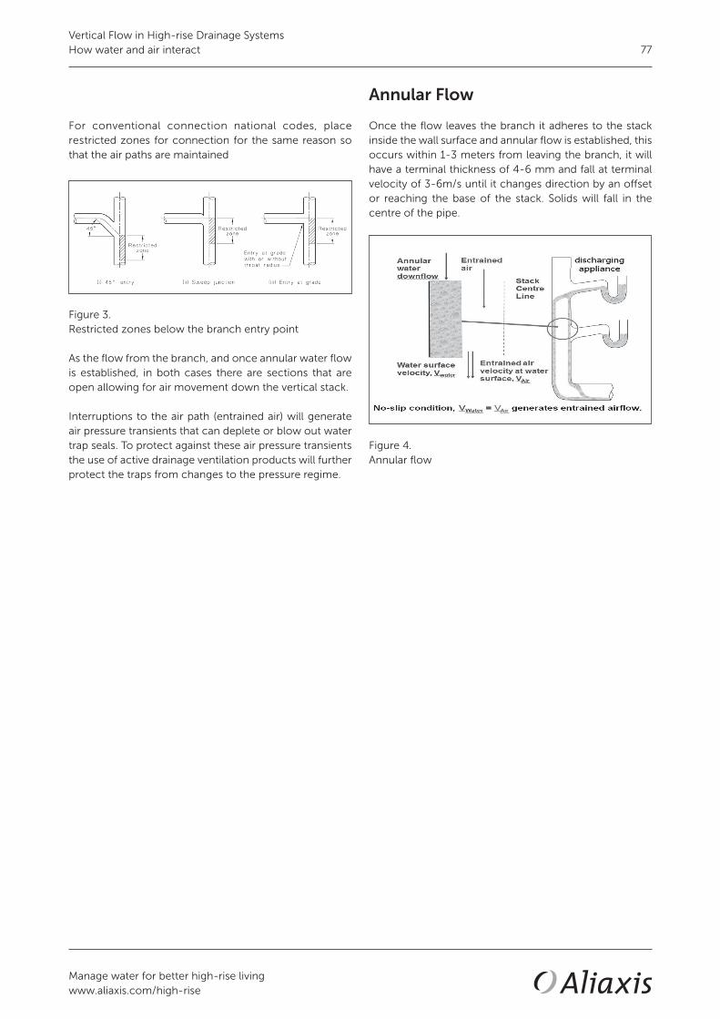
Manage water for better high-rise livingwww.aliaxis.com/high-rise
77
For conventional connection national codes, place restricted zones for connection for the same reason so that the air paths are maintained
Figure 3.Restricted zones below the branch entry point
As the flow from the branch, and once annular water flow is established, in both cases there are sections that are open allowing for air movement down the vertical stack.
Interruptions to the air path (entrained air) will generate air pressure transients that can deplete or blow out water trap seals. To protect against these air pressure transients the use of active drainage ventilation products will further protect the traps from changes to the pressure regime.
Annular Flow
Once the flow leaves the branch it adheres to the stack inside the wall surface and annular flow is established, this occurs within 1-3 meters from leaving the branch, it will have a terminal thickness of 4-6 mm and fall at terminal velocity of 3-6m/s until it changes direction by an offset or reaching the base of the stack. Solids will fall in the centre of the pipe.
Figure 4.Annular flow
Vertical Flow in High-rise Drainage SystemsHow water and air interact

Manage water for better high-rise livingwww.aliaxis.com/high-rise
78
Conclusion
In high-rise buildings with their increased loadings and high usage patterns, the flows within the stack have an influence on the operation of the drainage system. The flows from the appliance through its water trap seals enters the branch pipe work, the fittings from the branch to the stack must be correct to ensure that there is minimal air closure of the air path to reduce the pressure fluctuations within the system.
Using swept or angled fittings reduce the potential for the air path blockages, but higher discharge rates at any point in time may block the air path, generating air pressure transients that can deplete water trap seals. Using active drainage ventilation products will reduce the air pressure transients and their harmful effects ensuring that the water trap seals are maintained.
Using stack-aerators to separate the discharge from the branch to the vertical stack ensure that the air path is maintained within the vertical stack and reduces potential for the air path to be blocked.
Once the flow becomes annual it will fall at terminal velocity within one to two floors until it reaches the base of the stack. The terminal thickness of the annular flow will be 4-6mm, with the core of the pipe allowing for solids to fall and the air core for the entrained air flow until it reaches an offset or the base of the stack.
Steve WhiteTechnical Director DWVAliaxis High-Rise Building Solutions
MSc (Ir.) Marc Buitenhuis MTDResearch Engineer Hydro-DynamicsAliaxis
1. Swaffield J. A. and Galowin L.S., (1992) ‘The engineered design of building drainage systems’, Ashgate Publishing Limited, England
2. Swaffield JA (2010). Transient Airflow in Building Drainage Systems, published by Spon Press
3. Standard Australia (2003). Australian Standard AS/NZS 3500.2-2003
Read more technical papers related to this subject
• Relevance - Air Pressure transients in drainage systems• Relevance - Requirements for a well-designed high-rise drainage system• Solution - Stack-aerator system principles
09
/17/
124
Vertical Flow in High-rise Drainage SystemsHow water and air interact

Solutions• Active ventilation single stack drainage
• Air Admittance Valves (AAVs)
• Siphonic rainwater drainage
• Siphonic roof drainage systems
• Stack-aerator system principles
Manage water for better high-rise livingwww.aliaxis.com/high-rise
79


High-rise building solutions
Technical paper
Active air pressure suppression ofdrainage systems
From research to the marketplace
Steve White
Technical Director DWVAliaxis High-Rise Building SolutionsUnited Kingdom10/2017
Context of this paper
This technical paper is part of a library op technical papers. Refer to the below overview of all our technical papers and click on the title for a digital link.
Abstract
An insight into the post-development and operational issues related to active air pressure suppression is the utilisation of Air Admittance Valves (AAVs) together with the Positive Air Pressure Attenuator (P.A.P.A.) to provide full protection to a building’s drainage system. They provide protection to the water trap seals within the drainage system by dealing with the negative and positive transient pressures at source so they no longer become harmful to the trap seals. Negative and positive transient pressures are routinely generated within building drainage systems and their consequent harmful effects are well documented. Continuous research in this area has resulted in the P.A.P.A. and how it works alongside AAVs to provide active air pressure suppression. This paper focuses on the device’s acceptance into the marketplace and what the accepted solutions were throughout the world before the development of active air pressure suppression. This paper also considers the inherent dangers associated with an ad-hoc approach to the design of high-rise buildings in the absence of a workable standard.
Research Relevance Design Solutions Materials Installation Terminology Standards

Manage water for better high-rise livingwww.aliaxis.com/high-rise
82
Introduction
This paper focuses on the acceptance in the market place of active air pressure transient control and suppression; how it can provide superior protection to trap seals within high-rise buildings and the role that continuous research provides to the industry with design solutions that provide designers and contractors with up-to-date research, enabling engineers to design safe and effective solutions for high-rise drainage systems. The current design practices utilised for the design of high-rise building drainage and vent systems tend to fall outside many regional standards or codes and rely on the engineers to adapt the standard or code for their designs. The general understanding of the requirement for transient suppression in the industry tends to be limited, with the codes and standards not providing sufficient information for transient relief in the system. This leads to a number of designs being adapted with an ad-hoc approach and, in some cases, to a less efficient transient relief; thereby resulting in less protection for the trap seals within the system that is the only barrier between the drainage system and the living space. There is also concern that some of these designs are becoming standard practice and are then adopted as the basic standard or code for the region and, in some cases, becoming enforced by inspectors within the region. The market is generally traditional and change is sometimes hard to accept even though the research provides strong evidence that current practice is unsafe.
Active air pressure transient control
Active control uses a single stack design by utilising Air Admittance Valves (AAVs) to deal with the negative air pressures and the Positive Air Pressure Attenuator (P.A.P.A.) to attenuate any positive air pressure transients generated within the system.
Further research carried out by the drainage research group of Heriot-Watt University using AIRNET, a mathe- matical simulation model for air and pressure regimes in building drainage and ventilation systems, for a 50-storey building produced some surprising results, which are illustrated in Figures 1 and 2, especially considering that the conventional system analysed is very typical of high-rise drainage designs.
Figure 1.
Figure 2.
Active air pressure suppression of drainage systemsFrom research to the marketplace
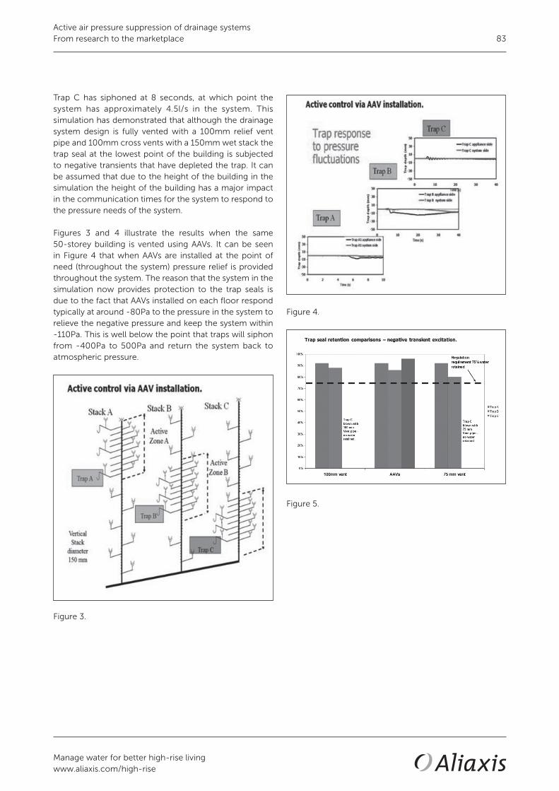
Manage water for better high-rise livingwww.aliaxis.com/high-rise
83
Figure 4.
Figure 5.
Trap C has siphoned at 8 seconds, at which point the system has approximately 4.5l/s in the system. This simulation has demonstrated that although the drainage system design is fully vented with a 100mm relief vent pipe and 100mm cross vents with a 150mm wet stack the trap seal at the lowest point of the building is subjected to negative transients that have depleted the trap. It can be assumed that due to the height of the building in the simulation the height of the building has a major impact in the communication times for the system to respond to the pressure needs of the system.
Figures 3 and 4 illustrate the results when the same 50-storey building is vented using AAVs. It can be seen in Figure 4 that when AAVs are installed at the point of need (throughout the system) pressure relief is provided throughout the system. The reason that the system in the simulation now provides protection to the trap seals is due to the fact that AAVs installed on each floor respond typically at around -80Pa to the pressure in the system to relieve the negative pressure and keep the system within -110Pa. This is well below the point that traps will siphon from -400Pa to 500Pa and return the system back to atmospheric pressure.
Figure 3.
Active air pressure suppression of drainage systemsFrom research to the marketplace

Manage water for better high-rise livingwww.aliaxis.com/high-rise
84
Figures 5 and 6 below illustrate the results when the same 50-story building is simulated by AIRNET for positive transients with half the hydraulic loading of 6.5 l/s. It can be seen by the simulation results that trap C has depleted due to positive transients. This indicates that the 100 mm relief vent which is in the design and commonly used is insufficient in diameter to divert the positive transient that is moving at 320 m/s away from the trap seals in the system. Further research is required to determine why a commonly sized venting system in high-rise buildings and its code does not provide the protection for which it is designed.
When the 50-storey building is designed as an active controlled system it can be seen that protection is provided throughout the system, as illustrated in Figures 7 and 8 below. By using AAVs and P.A.P.A. placed throughout the system the simulation results provided by AIRNET show the provision of the trap seals throughout the system with protection from negative and positive pressures. It is the concept of using AAVs and P.A.P.A. together that keeps the system pressure below -110Pa and thus the trap seals within the system are not subjected to the harmful pressures of over +- 400Pa.
Figure 6.
Figure 7.
Figure 8.
Figure 9.
Active air pressure suppression of drainage systemsFrom research to the marketplace

Manage water for better high-rise livingwww.aliaxis.com/high-rise
85
The involvement of research has demonstrated two major factors; firstly that high-rise buildings designed conventi-onally can be affected by negative and positive transients; and secondly that working with the industry there is a safe and practical solution to designing a high-rise building drainage and vent systems.
Figure 10.
Active control - is it a solution?
This paper has demonstrated that there is sufficient data for multiple-flush situations where active control provides superior protection to the system, as seen in the results of the simulations in Figures 4 and 8 from the 50-story Heriot-Watt study and that active control has been used to rectify problem systems by adding AAVs and P.A.P.A. to deal with positive and negative pressures in the system.
Taking the two factors of the scientific research carried out in active control and the fact that utilising AAVs and P.A.P.A. can problem solve existing systems, it is logical to design systems as fully active ventilated drainage systems from the start to provide the system with:• reduced system complexity; • reduced time of installation and labour;• reduced material used in the system, bringing sustainability
to the design; • increased predictability of system operation;• ability to place suppression between transient source
and appliance trap seals to be protected;• interception of transients prior to propagation
throughout the network and impact on all connected appliance trap seals.
The drainage system becomes a single stack system that can vent buildings from 10 floors to over 100 floors in height and keeps the system pressures in the region of +- 110Pa; well below the +- 400Pa that affect the trap seals in the system designed in Figure 15.
Figure 11.
Active air pressure suppression of drainage systemsFrom research to the marketplace

Manage water for better high-rise livingwww.aliaxis.com/high-rise
86
Conclusion
Over the last decade there has been an unprecedented increase in high-rise buildings around the world requiring engineering disciplines to meet the requirements in structural and system operation to these types of buildings. In regards to drainage, has this been met? This paper highlighted and asked the question if the standards and codes meet these demands for high-rise building designs. The leading research carried by Heriot-Watt University has demonstrated that the current standard and code requirements may not be sufficient in their recommendations to provide effective guidance to the engineering community to design workable safe systems. There are many cases where the recommendations in the standards have been modified by the engineers as they have experienced problems in previous designs and wish to engineer out problems in future buildings. Sometimes this has been restricted by the regulators within different states due to their insistence that the code is followed as it is written, and therefore engineers are unwilling to deviate from this even if it means that the system may become susceptible to fail. Drainage is a relatively easy system to understand for any type of building design: Hydraulic loading for the sizing of pipes; and a venting system that keeps the pressures below +- 400Pa throughout the system. If the pressures are kept well below this, in the region of +- 200Pa, there is less stress placed on the water trap seals within the system. With a passive system there is a single limitation in that the only way to relieve the transient pressures is through a network of ventilation pipes that terminate at the top of the building. Is the sizing of these ventilation pipes sufficient for the demands of a high-rise building? The research shows through the simulations for high-rise buildings that with vents smaller than the stacks the system will fail. It also proves that active drainage ventilations work for the same loadings. There is also a lack of education within the industry as to how the drainage system operates and more is needed to improve this by providing up-to-date research and improvement in the education of the engineers. Active control of drainage systems has been thoroughly researched and with over 50 high-rise buildings operating to this principle without issues, this system meets the demands of high-rise drainage ventilation. At present it is the only system that is proven to do this and this could only be achieved by the cooperation of researchers and industry working together to provide a solution that meets the demands of the buildings being built.
Steve WhiteTechnical Director DWVAliaxis High-Rise Building Solutions
MSc (Ir.) Marc Buitenhuis MTDResearch Engineer Hydro-DynamicsAliaxis
1. BSI British Standard Institution (2004). European Standard BS EN 12056-2:2000
2. International Code Council (2003). US Standard International Plumbing Code-IPC
3. International Association of Plumbing and Mechanical Officials (2003). US Standard Uniformed Plumbing Code-UPC
4. Standard Australia (2003). Australian Standard AS/NZS 3500.2-2003
5. Wang Xuejiao (2007). Study on flux capacity of single stack drainage system: Non-Roof, Penetration Self Circulating Drain System Stack Tongji University
Read more technical papers related to this subject
• Design - Limiting roof penetrations in high-rise buildings• Design - Offsets in Building Drainage systems• Materials - DWV systems and fire safety• Solution - Stack-aerator system principles• Technical Paper - Solution - Active Ventilation Single Stack Drainage 0
9/1
7/13
3
Active air pressure suppression of drainage systemsFrom research to the marketplace

High-rise building solutions
Technical paper
Air Admittance Valves (A.A.V.’s)
Active trap seal protection forhigh-rise drainage
Steve White
Technical Director DWVAliaxis High-Rise Building SolutionsUnited Kingdom10/2017
Context of this paper
This technical paper is part of a library op technical papers. Refer to the below overview of all our technical papers and click on the title for a digital link.
Abstract
Air Admittance Valves (A.A.V.s) are one way valves which allow air to enter the drainage system but do not allow air to escape through the valves. Their purpose is to limit the pressure fluctuations within the drainage system and to protect water trap seals. A.A.V.s are commonly used in multi-storey buildings as Group / Branch / Stack vents. The A.A.V.s are often preferred for this use as they are easy to install, use less space and provide ready access for maintenance cleaning of the waste pipe should a blockage occur. A.A.V.s provide better protection to the branch fixtures than an open vent as they sense the pressure fluctuation at the source (Point of Need (P.O.N.)) and equalize the system in less than 0.3 seconds, whereas the open vent method could take 1 second to equalize the system in a large building with a single flush. If there are multiple flushes, then the conventional passive system may never catch up with the demands of the system and lead to the depletion of the trap seals. When A.A.V.’s are used in a branch vent situation, the height of the building is not relevant as the A.A.V. is only venting the group of fixtures.
Research Relevance Design Solutions Materials Installation Terminology Standards

Manage water for better high-rise livingwww.aliaxis.com/high-rise
88
Introduction
The traditional method, to protect water trap seals (for example P-traps) is to use pipe network (passive drainage venting) that will reach to atmosphere, usually at the top of the building.
One of the key purposes of the vents to atmosphere is to allow air to enter the pipes to reduce the pressure fluctuations within the network, so that water trap seals are maintained.
The issue with this practice, in high-rise and complex buildings, is the time that it takes for a system to respond due to the pipe period, from the P.O.N. to the vent at the top of the buildings.
The issue is even greater when there are multiple discharges on the same system within a very short period - 3-15 seconds.
A pipe period is defined as, the time taken tp, for a transient
travelling at acoustic velocity c, generated by a change of flow conditions to reach the system boundary (roof penetration) and return to its source 2L.
Why is there a need to vent the drainage system?
If we do not protect the water trap seals smells and disease can enter into our living or surrounding spaces. Protection may be provided by using the passive venting but the requirements in codes have been based on research for lower buildings.
In high-rise and more complex buildings the vent lengths are greater by providing relief with A.A.V’s at the P.O.N.; this reduces the response time and provides faster protection for the water trap seals.
The conventional thinking in drainage venting is to deal with the negative pressure. The established thinking is water trap seals are depleted due to siphonic action. The most common causes are “self siphonage” and “induced siphonage”.
Self siphonage
A negative pressure transient occurs when there is a discharge of fixtures to which the trap seal is connected. This can have the effect of reducing the trap seal (or pulling the trap). This occurs ats the momentum acquired by the waste passes through the fixture and down the trap seal. This momentum is transferred directly into the trap seal and trap seal loss occurs. This is commonly known as ‘self siphonage’ and is not specifically related to high-rise.
Figure 2.Self siphonage
Figure 1.Transient pressure regimes
One solution is the use of A.A.V.’s, to bring the air into the drainage system at the Point of Need (P.O.N). They provide the same function as the vent to atmosphere without the time delay, and are proven to provide better protection for the water traps seals than a vent pipe network, because of the faster reaction time.
Air Admittance Valves (A.A.V.’s)Active trap seal protection for high-rise drainage

Manage water for better high-rise livingwww.aliaxis.com/high-rise
89
How Air Admittance Valves work
The A.A.V.’s should open before -75 Pa, allowing air into the system and relieving the negative transient pressure.
This keeps the pressures in the system for discharges between 0 and -250 Pa. If the system goes above these pressures, this can lead to the depletion of the trap seals.
A.A.V.’s work by utilizing a reverse lift membrane. When there is water movement in the system the valve will open; when the movement of water stops, the A.A.V. will seal airtight by gravity.
Figure 4.A.A.V. operation
The valves open and admit fresh air when negative pressure occurs from the fixture discharge. This equalizes pressure within the system and so protects the trap seals. When the flow stops, the valve closes and seals airtight by gravity, preventing any transmission of foul air out through the A.A.V. or the fixture. A.A.V.s are tested for product approvals from -30Pa (lowest point a testing institute can accurately measure) through to -10KPa, so that the valves can be placed up to one meter below the flood level of the appliance.
Induced siphonage
The most common, critical and also unknown aspects about trap seal depletion in multi-storey and high-rise buildings occurs when there is a pressure fluctuation caused by a discharge of another fixture in the system other than the fixture to which the trap is connected. This is called “induced siphonage”. As the water falls down the pipe and passes the branch pipe connected to it, it draws air from it, thus creating a partial vacuum and sub-sequently siphonage of the trap can take place.
Figure 3.Trap seal breach
Air Admittance Valves (A.A.V.’s)Active trap seal protection for high-rise drainage

Manage water for better high-rise livingwww.aliaxis.com/high-rise
90
Minium requirements for A.A.V.’s used in high-rise buildings
As there are many types of A.A.V.s on the market it should be noted that not each product is suited for use in high-rise building drainage. The criteria for A.A.V.s in high-rise buildings are stricter as the correct system operation to prevent any trap seal from breaching depends on the lifetime operational quality of all the A.A.V.s installed. The lifetime operational quality depends on the following 4 factors:
1. Opening reaction time: the quicker the better a. High-rise building drainage systems are subject to ongoing multi flushes, i.e. the continuously unsteady nature makes the system to constantly react to negative transients, as fast as possible. b. Reverse cone of the cap allows to neutralise any internal condensation that might affect the membrane opening ability.
2. Zero maintenance a. In high-rise buildings, the A.A.V.’s are often hidden in difficult accessible locations, therefore the less maintenance the better. b. Compact overall dimension. c. Double screen protection (internally and externally) against foreign material or insects.
3. 100% closing ability: a. Dry membrane for consistent life time functioning, not depending on lubrication. b. 500K cycle endurance testing. c. Sealed design.
4. Life time product warranty a. ABS plastic + 100% silicone: the best material for durability. b. UV protection and anti mould protection. c. Meet most international product standards. d. External use and up to -40C (for stack A.A.V.’s). e. Full connection flexibility to any type of pipe material.
Air Admittance Valves (A.A.V.’s)Active trap seal protection for high-rise drainage

Manage water for better high-rise livingwww.aliaxis.com/high-rise
91
Conclusion
A.A.V.s have been available for use in the world market since the 1970s. They are included in many plumbing codes around the world. The definition within the EN 12056-2 for the purpose of vent pipes and air admittance valves is the same.
In more complex drainage systems with longer pipe networks and higher loadings, the ability to place an A.A.V. at the P.O.N means that the negative transients are reduced faster than the time a passive pipe network can respond and therefore the A.A.V.s as part of an active drainage venting solution provide greater protection to water trap seals and maintaining the barrier between the drainage system and the living space within the building.
It is also that the A.A.V. does not just open quickly, but it must be robust enough to withstand the greater loading pressures in high-rise and complex buildings. Therefore for A.A.V.s used in taller buildings should be tested up to a pressure of 10KPa, the upper tightness test within the EN 12380, the ASSE 1050 and the ASSE 1051, which are the main A.A.V. products standards in the world. It is also recommended that the A.A.V.s are third party tested and have third party approvals.
Steve WhiteTechnical Director DWVAliaxis High-Rise Building Solutions
MSc (Ir.) Marc Buitenhuis MTDResearch Engineer Hydro-DynamicsAliaxis
1. Swaffield JA (2010). Transient Airflow in Building Drainage Systems, published by Spon Press
2. EN 12056:2000 ‘Gravity Drainage Systems inside buildings Part 2: Sanitary Pipework, layout and calculations’, British Standards Institute, London
3. Studor design guide 2012
Read more technical papers related to this subject
• Design - Limiting roof penetrations in high-rise buildings• Design - Offsets in Building Drainage systems• Materials - DWV systems and fire safety• Solution - Stack-aerator system principles• Technical Paper - Solution - Active Ventilation Single Stack Drainage
09
/17/
121
Air Admittance Valves (A.A.V.’s)Active trap seal protection for high-rise drainage


High-rise building solutions
Technical paper
Principles of siphonic roof drainage systems
MSc (Ir.) Marc Buitenhuis MTD
Research Engineer Hydro-DynamicsAliaxisThe Netherlands10/2017
Context of this paper
This technical paper is part of a library op technical papers. Refer to the below overview of all our technical papers and click on the title for a digital link.
Abstract
In this article it has been illustrated that a siphonic roof drainage system with a single roof outlet is reasonably well understood. The governing equations are presented. The basic design of the system can be determined using single phase flow theory assuming full bore flow of the system. The start up and two phase flow functioning of the system are more complex. In a multiple roof outlet siphonic system the interaction between the roof outlets makes it very complex and only skilled people can design a well functioning system.
Research Relevance Design Solutions Materials Installation Terminology Standards

Manage water for better high-rise livingwww.aliaxis.com/high-rise
94
Introduction
For drainage of large roof areas a siphonic system is a well acknowledged cost saving solution. The principle of expelling air from the system means that only water is being transported at high speed making use of the suction pressure created behind the full bore water column. The high speed full bore flow makes smaller pipe dimensions than in conventional systems possible.
Also the elimination of multiple downpipes and a lot of piping in the groundwork mean a large cost saving and more architectural freedom for the building design.
The only disadvantage is that one has to have a better technical background to be able to properly design a siphonic system. A multiple roof outlet siphonic system is a complex system that needs to be carefully optimized to function properly.
In this article the theory of a single roof outlet siphonic roof drainage will be explained to give a basis for the principles of a multiple roof outlet system.
Principle of syphonic roof drainage
The principle in syphonic roof drainage is the full bore flow of the system. One thus has to obtain and maintain a full bore flow for optimal functioning of the system.
The full bore flow is initiated by the hydraulic jump (see figure 1) at the entrance of the horizontal part of tail pipe or collector pipe of the system. The shape of the hydraulic jump depends on 2 parameter: • the velocity of the flow streaming into the horizontal pipe • and the resistance of the pipe beyond the entrance of
the collector pipe.
Figure 1.Forming of the hydraulic jump at start up of siphonic roof drainage system
The principle can be compared to the stream of vehicles on highways or race tracks. Vehicles can accelerate optimally on roads that are straight and keep on being straight for miles. As soon as there is a curve in the road the vehicles have to slow down. When the first vehicle decelerates the one behind him has to decelerate also and the distance between the vehicles is decreasing. This is very often the moment for accidents to happen: there is an increasing chance for collision. Exactly this is the case for fluid particles in a stream. When particles are redirected from the vertical downfall to horizontal flow the fluid is decelerated. As fluid particles have no brakes they will collide and the only way they can go is up, creating height and thus a hydraulic jump. The above explains 2 things: first of all why an increasing length of vertical tail pipe leads to earlier priming, second why an increasing resistance in the col-lector pipe leads to this same result. An increasing length of tail pipe leads to more time to accelerate the fluid coming from the roof, thus to higher velocities in the bend to the horizontal pipe. This will lead to a higher hydraulic jump when the flow is decelerated in the horizontal pipe. Also the more the flow is decelerated in the horizontal pipe, thus the higher the resistance downstream of the bend, the higher the hydraulic jump will be. The higher the hydraulic jump is the earlier the full pipe diameter will be closed off by water and priming will start. When the horizontal pipe is (slightly) inclined the water will run off easier and thus the hydraulic jump will be less pronounced, delaying the onset to priming of the system.
Principles of siphonic roof drainage systems

Manage water for better high-rise livingwww.aliaxis.com/high-rise
95
In a steady incompressible inviscid full bore flow integration of Euler’s equations over a streamline gives the well known Bernoulli equation:
This equation is often referred to to easily explain the principle of siphonic roof drainage.
The head loss in pipe systems consists of losses due to the friction coefficient of the pipe walls, losses due to the fittings (bends, knees, T-pieces and the roof outlet) and losses due to the additional roughness caused by welding of pipes and fittings.The head loss due to friction along the pipe walls can be described by the equation:
with f the friction factor. For the determination of the friction factor the Colebrook-White equation is most widely applied:
with ks the equivalent sand grain roughness. A good
estimation for f is:
The head losses of fittings and roof outlets can be approxi-mated in a similar way by:
with ξ a coefficient specific for each fitting of a certain diameter and Le an equivalent length of pipe.
Theoretical background
In fluid dynamics the Navier-Stokes equations are the general form of the momentum equations that account for fluid motion and are written as:
For incompressible inviscid flow they become:
and are known in this form as Euler’s equations.The headloss ΔH is defined as:
Substituting this in the above Euler’s equations and dividing by ρ gives:
In streamline coordinates along the x-axis and taking the z-direction the direction of gravity:
With a constant diameter of the pipe and thus constant cross section, A, this can be further rewritten to:
with β the angle between the streamline x and the direction perpendicular to the gravity (β positive when the streamline ascends).
For a descending collector pipe the angle β thus is negative, the term with this parameter thus positive, driving the speed in the collector pipe up and thus making it decelerate less, producing a less pronounced hydraulic jump and thus delaying priming (full bore flow) in the system.
Principles of siphonic roof drainage systems

Manage water for better high-rise livingwww.aliaxis.com/high-rise
96
Conclusion
In this article it has been illustrated that a siphonic roof drainage system with a single roof outlet is reasonably well understood. The governing equations are presented.
The basic design of the system can be determined using single phase flow theory assuming full bore flow of the system. The start up and two phase flow functioning of the system are more complex.
In a multiple roof outlet siphonic system the interaction between the roof outlets makes it very complex and only skilled people can design a well functioning system.
Steve WhiteTechnical Director DWVAliaxis High-Rise Building Solutions
MSc (Ir.) Marc Buitenhuis MTDResearch Engineer Hydro-DynamicsAliaxis
1. Robert W. Fox, Alan T. McDonald, Introduction to fluid mechanics, third edition, 1985, School of Mechanical Engineering Purdue University, John Wiley & Sons
2. Scott Arthur, John A. Swaffield, Siphonic roof drainage: current understanding, 2001, Water research group, Department of civil and offshore engineering, Heriot-Watt University, Edinburg, Scotland (UK)
3. G.B. Wright, S. Arthur, J.A. Swaffield, Numerical simulation of the dynamic operation of multi-outlet siphonic roof drainage systems, 2005, Drainage and water supply research group, School of the build environment, Heriot-Watt University, Edinburg, Scotland (UK)
4. Scott Arthur, The priming focused design of siphonic roof drainage, drainage research group, School of the built environment, Heriot-Watt University, Edinburg, Scotland (UK)
5. S. Arthur, G.B. Wright, Siphonic roof drainage systems – priming focused design, 2006, School of the built environment, Heriot-Watt University, Edinburg, Scotland (UK)
6. S. Arthur, J.A. Swaffield, Siphonic roof drainage system analysis utilizing unsteady flow theory, 2000, Department of building engineering and surveying, Heriot-Watt University, Edinburg, Scotland (UK)
Read more technical papers related to this subject
• Design - Limiting roof penetrations in high-rise buildings• Design - Offsets in Building Drainage systems• Materials - DWV systems and fire safety• Solution - Stack-aerator system principles• Technical Paper - Solution - Active Ventilation Single Stack Drainage
09
/17/
134
Principles of siphonic roof drainage systems

High-rise building solutions
Technical paper
Siphonic roof drainage systems
The road to priming
MSc (Ir.) Marc Buitenhuis MTD
Research Engineer Hydro-DynamicsAliaxisThe Netherlands10/2017
Context of this paper
This technical paper is part of a library op technical papers. Refer to the below overview of all our technical papers and click on the title for a digital link.
Abstract
In this article the startup of a siphonic roof drainage system is described. It is intended to give better insight in the behavior of the system and help design systems that will work optimally and siphonic more often.
The development of the hydraulic jump and the elimination of air from the system by the suction power in the downpipe are key items in the development of siphonic functioning.
Research Relevance Design Solutions Materials Installation Terminology Standards

Manage water for better high-rise livingwww.aliaxis.com/high-rise
98
Introduction
Siphonic roof drainage systems are designed to operate with full bore flow. The computations made for siphonic roof drainage systems therefore focus on single phase water flow. For the proper design of the maximum capacity of a siphonic system this is sufficient.
However it is necessary to have a good insight in the start up phase to siphonic functioning of the system as well. Most of the times the rain intensity will not be high enough to get the system to work siphonic. It is preferable to have the system work siphonic once or twice a year at least to self clean the system of debris. Also when the system works siphonic the noise production is lower than with two-phase flow (combined water/air flow).
In this article the start up phase will be described to have a better understanding of the phenomena and develop measures to stimulate full bore flow.
Start-up phase
When the rain starts the roof drainage system slowly starts up. At first the water flows into the roof outlet at a low rate and shallow water level. The water flows along the vertical walls of the tail pipe creating an annular flow. At the bend to the horizontal tail pipe or collector pipe the flow collects at the bottom of the bend resulting in a separated flow in the horizontal pipe. In the downpipe behind the collector pipe the water is forming an annular flow again.
This is independent of the water velocity streaming into this pipe. The flow can follow the inner contour of the bend or splash onto the opposite wall. The point at which the annular flow is reinstalled will differ, as will the pressure distribution when the pipe is closed off by the splashing water.
At some higher flow rates the separated flow in the horizontal pipes will become wavy.
Figure 1. Flow regimes in vertical pipes: annular, slug and bubble flow
Siphonic roof drainage systemsThe road to priming

Manage water for better high-rise livingwww.aliaxis.com/high-rise
99
Figure 2. Flow regimes in horizontal pipes: straight, wavy and slug flow
Siphonic roof drainage systemsThe road to priming

Manage water for better high-rise livingwww.aliaxis.com/high-rise
100
Hydraulic jump
When the water streams down the vertical tailpipe it is accelerated by gravity. When it flows into the horizontal pipe the flow is decelerated forming a hydraulic jump.
The principle can be compared to the stream of vehicles on highways or race tracks. Vehicles can accelerate optimally on roads that are straight and keep on being straight for miles. As soon as there is a curve in the road the vehicles have to slow down. When the first vehicle decelerates the one behind him has to decelerate also and the distance between the vehicles is decreasing. This is very often the moment for accidents to happen: there is an increasing chance for collision. Exactly this is the case for fluid particles in a stream. When particles are redirected from the vertical downfall to horizontal flow the fluid is decelerated. As fluid particles have no brakes they will collide and the only way they can go is up, creating height and thus a hydraulic jump.
The above explains 2 things: first of all why an increasing length of vertical tail pipe leads to earlier priming, second why an increasing resistance in the collector pipe leads to this same result.
An increasing length of tail pipe leads to more length to accelerate the fluid coming from the roof, thus to higher velocities in the bend to the horizontal pipe. This will lead to a higher hydraulic jump when the flow is decelerated in the horizontal pipe.
Also the more the flow is decelerated in the horizontal pipe, thus the higher the resistance downstream of the bend, the higher the hydraulic jump will be.
Eventually the hydraulic jump will close off the whole pipe diameter, leading to below atmospheric pressures in the system behind the closure and priming will start.
Start of priming
When the hydraulic jump closes off the whole periphery of the pipe the air behind the jump has only one way to leave the system and that is through the downpipe. To transport the air through the downpipe the friction forces between the water and the air have to overcome the buoyancy forces of the air. In other words the water has to drag the air along against its tendency to rise. To make this happen the flow rate has to increase further.
Measures to enhance priming
As stated above to enhance the priming of the system a longer tail pipe can be chosen or the deceleration of the flow in the horizontal pipe can be increased in order to make the hydraulic jump close off the periphery of the pipe as quickly as possible leading to earlier priming
Figure 3. Hydraulic jump
Siphonic roof drainage systemsThe road to priming
Manage water for better high-rise livingwww.aliaxis.com/high-rise
101
Conclusion
In this article the start-up of a siphonic roof drainage system has been described. It is intended to give better insight in the behaviour of the system and help design systems that will work optimally and siphonic more often.
The development of the hydraulic jump and the elimination of air from the system by the suction power in the downpipe are key items in the development of siphonic functioning.
To reach siphonic drainage as quickly as possible a longer vertical tailpipe as well as a quick deceleration in the horizontal pipe is preferable.
Steve WhiteTechnical Director DWVAliaxis High-Rise Building Solutions
MSc (Ir.) Marc Buitenhuis MTDResearch Engineer Hydro-DynamicsAliaxis
1. Fox, Robert W. , McDonald, Alan T., Introduction to fluid mechanics, third edition, 1985, School of Mechanical Engineering Purdue University, John Wiley & Sons
2. Scott Arthur, John A. Swaffield, Siphonic roof drainage: current understanding, 2001, Water research group, Department of civil and offshore engineering, Heriot-Watt University, Edinburg, Scotland (UK)
3. G.B. Wright, S. Arthur, J.A. Swaffield, Numerical simulation of the dynamic operation of multi-outlet siphonic roof drainage systems, 2005, Drainage and water supply research group, School of the build environment, Heriot-Watt University, Edinburg, Scotland (UK)
4. Scott Arthur, The priming focused design of siphonic roof drainage, drainage research group, School of the built environment, Heriot-Watt University, Edinburg, Scotland (UK)
5. S. Arthur, G.B. Wright, Siphonic roof drainage systems - priming focused design, 2006, School of the built environment, Heriot-Watt University, Edinburg, Scotland (UK)
6. S. Arthur, J.A. Swaffield, Siphonic roof drainage system analysis utilizing unsteady flow theory, 2000, Department of building engineering and surveying, Heriot-Watt University, Edinburg, Scotland (UK)
Read more technical papers related to this subject
• Materials - DWV systems and fire safety• Research - Rainfall intensity used for siphonic rain water drainage
09
/17/
117
Siphonic roof drainage systemsThe road to priming


High-rise building solutions
Technical paper
Stack-aerator system principles
Balancing the pressures
MSc (Ir.) Marc Buitenhuis MTD
Research Engineer Hydro-DynamicsAliaxisThe Netherlands10/2017
Context of this paper
This technical paper is part of a library op technical papers. Refer to the below overview of all our technical papers and click on the title for a digital link.
Abstract
In this paper the principles of the Stack-aerator systems will be presented. Balancing the pressures in the system and keeping them close to atmospheric is the main issue for these systems in order to keep the water traps of sanitary devices in place. An open path to the environment must be present for all the air in the system to avoid pressure surges and thus blow outs of siphons. To achieve this special fittings are used on every level of the building where branches enter the stack.
Research Relevance Design Solutions Materials Installation Terminology Standards

Manage water for better high-rise livingwww.aliaxis.com/high-rise
104
Introduction
A lot of waste water is produced daily by toilets, bath tubs and showers, dishwashers, washing machines, etc. It all has to be drained from the buildings and transported to the sewage facilities.
If a single drainage pipe would be used that is just capable of draining the maximum amount of waste water, large pressure peaks would result, sucking dry or blowing out all water traps, giving access for bad odors to enter the living spaces.
In order to keep the pressure fluctuations low the system has to be ventilated. An additional ventilation stack can do the job, but is a more complicated construction, costing considerably more, and takes up more valuable space in building shafts. The answer is a single stack system using stack-aerators. The principle of this system is based on keeping a free path for air to leave or enter the system, thereby keeping the pressure level within acceptable limits.
Figure 1. Schematic of a single stack system with stack-aerators
Stack-aerator system principles Balancing the pressures

Manage water for better high-rise livingwww.aliaxis.com/high-rise
105
Stack-aerator system
When fluid is transported in a pipe system at a low discharge rate relative to the maximum discharge rate of the pipe system a so called annular flow will occur in the vertical pipes. This means that the water will flow along the walls in an annulus independent of the initial inflow conditions.In the center of the pipe a core of air will occur. If the vertical stack sticks through the roof and is open the core of air will always remain at approximately the atmospheric pressure.
This in contrast to a plug flow that can block the air path at any location in the pipe system. In front of the plug of water that cuts off the open air path a pressure peak will occur, whereas a wake with a vacuum behind the plug will be present. The pressure peak in the front will also enter the side branches and possibly blow out the water traps. When the water traps are able to withstand the pressure peaks they are threatened a moment later by the vacuum of the wake that can suck them dry. Both will lead to an open path for smelly sewer gases to enter the building.
To keep the water traps in place the pressure has to be kept at approximately atmospheric level in the side branches also. To manage this the air in the branches have to be in contact with the air core of the stack at all times. This is where the stack-aerator plays an important role.
Figure 2.Stack-aerator
In the branches the air is located at the upper half of the horizontal pipe (gravity driven separated flow). If the horizontal branch is plugged straight into the stack the water would jet in with sufficient force to disrupt the core of air and thus disturbing the pressure balance in the system. The stack-aerator collects the water in a separate mixing chamber [1] before it drops down and flows in vertically to the main stream. The air in a branch connects with the core of air in the stack through a ventilation hole [2].
The main vertical water stream is offset by the deflection in the bend [3] of the stack-aerator.
At the bottom of the vertical stack the flow is channeled horizontally. The system has to maintain ventilated through this bend also. Directly after this bend there is a risk the system will be blocked by the hydraulic jump that will occur because of the deceleration of the water in the corner. This threat can be alleviated by constructing a short ventilation stack from just before the bend to a location in the horizontal pipe behind the hydraulic jump as shown in Figure 1.
2.
3.
1.
Stack-aerator system principles Balancing the pressures

Manage water for better high-rise livingwww.aliaxis.com/high-rise
106
Conclusion
The single stack system with stack-aerators system is all about keeping the air pressure in the system near atmospheric in order to keep the water traps in place. The special shape of the stack-aerators contribute to a higher capacity whilst keeping the core of air open to ventilate the traps. The hydraulic jump at the base of the stack blocking the ventilation of the system is by-passed using a pressure relief line.
Steve WhiteTechnical Director DWVAliaxis High-Rise Building Solutions
MSc (Ir.) Marc Buitenhuis MTDResearch Engineer Hydro-DynamicsAliaxis
1. Robert W. Fox, Alan T. McDonald, Introduction to fluid mechanics, third edition, 1985, School of Mechanical Engineering Purdue University, John Wiley & Sons
2. Arthur, Scott, Swaffield, John A., Siphonic roof drainage: current understanding, 2001, Water research group, Department of civil and offshore engineering, Heriot-Watt University, Edinburg, Scotland (UK)
3. Swaffield, John A., Wise, A.F.E., Water Sanitary and Waste Services for Buildings, May 1995
4. Swaffield, John A., Galowin, L.S., The engineered design of building drainage systems, Oct 1992, Ashgate Publishing Company
Read more technical papers related to this subject
• Materials - DWV systems and fire safety• Relevance - High-rise design practice and codes• Relevance - Requirements for a well-designed high-rise drainage system • Research - What happens at the base of the stack• Solution - Active Ventilation Single Stack Drainage
09
/17/
117
Stack-aerator system principles Balancing the pressures

Materials• DWV systems and fire safety
Manage water for better high-rise livingwww.aliaxis.com/high-rise
107


High-rise building solutions
Research Relevance Design Solutions Materials Installation Terminology Standards
Technical paper
DWV systems for fire safety
Metal vs Plastic
Steve White
Technical Director DWVAliaxis High-Rise Building SolutionsUnited Kingdom10/2017
Context of this paper
This technical paper is part of a library op technical papers. Refer to the below overview of all our technical papers and click on the title for a digital link.
Abstract
This paper describes fire safety of plastic DWV pipe systems in high-rise buildings. How a fire builds up through four stages and how a passive fire system compartmentalises and limits the spread of fire and smoke in order for the active fire system to take over. It describes the difference between metal DWV systems and plastic DWV systems when it comes to fire safety.

Manage water for better high-rise livingwww.aliaxis.com/high-rise
110
Fire compartmentation
Passive fire protection via compartmentation is important for life safety and property protection by dividing a building into smaller blocks, vertical fire resistant walls and horizontal fire resistant floors, to limit the fire spread and gain time. Compartmentation plays an important role in a building when the active system of the fire area is no longer able to control the fire. Fire in a building evolves in four stages.
Incipient stageThe incipient stage begins when heat, oxygen and a fuel source combine and have a chemical reaction resulting in fire. This is also known as “ignition” and is usually represented by a very small fire which often goes out on its own, before the following stages are reached. Recognizing a fire in this stage provides your best chance at suppression or escape.
Growth stageThe growth stage is where the structures fire load and oxygen are used as fuel for the fire. There are numerous factors affecting the growth stage including where the fire started, what combustibles are near it, ceiling height and the potential for “thermal layering”. It is during this shortest of the four stages when a deadly “flashover” can occur; potentially trapping, injuring or killing firefighters.
Fully developed stageWhen the growth stage has reached its max and all combustible materials have been ignited, a fire is considered fully developed. This is the hottest phase of a fire and the most dangerous for anybody trapped within.
Figure 1.
DecayUsually the longest stage of a fire, the decay stage is characterized a significant decrease in oxygen or fuel, putting an end to the fire. Two common dangers during this stage are first - the existence of non-flaming combus-tibles, which can potentially start a new fire if not fully extinguished. Second, there is the danger of a backdraft when oxygen is reintroduced to a volatile, confined space.
Introduction
Fire safety protection is critical in developing high-rise buildings. Fire is a grave threat to people and property. High-rise buildings present unique challenges not found in traditional low-rise buildings: longer egress times and distance, fire department accessibility, smoke movement and fire control, and the need for more complex evacuation strategies. Piping systems are at the heart of a building and play a critical role in ensuring fire safety. As more and more people live in a single building connected to a single system, the need for a safe and reliable sanitary system increases.
Active and passive fire protection
Inside buildings there are two types of fire protection systems, Active Fire Protection and Passive Fire Protection, and both systems should actively work together in the event of a fire.
Active fire protection is a group of systems that require action in the event of a fire. This action can be manual, like a fire extinguisher, or automatic like a sprinkler system. When fire and or smoke is detected these system put out or slow the growth of the fire until firefighters arrive.
Passive fire protection is a group of systems that compart-mentalize a building through the use of fire-resistance rated walls and floors, keeping the fire from spreading quickly and providing time to escape for people in the building.
DWV systems for fire safety Metal vs Plastic

Manage water for better high-rise livingwww.aliaxis.com/high-rise
111
Compartmentation during growth stage
A fire out of control occurs when the fire is at the flashover stage where everything that is combustible in a room is inevitably lost and one can only try to save the neighbouring rooms or buildings.
Burnable hot gases are concentrated below the ceiling and are heated up due to the fire in the room. When this mixture of gases is hot enough, the flashover happens and a “wave” of fire rolls along the ceiling.
A flashover does not occur in every fire compartment. The fuel must have sufficient heat energy to develop flashover conditions and the fire must have sufficient oxygen.
Plastics vs metal and fire safetyAlthough most metal pipes are classified as Non-Combustible, and plastic pipes as Combustible, one needs to have a closer look at which drain, waste and vent (DWV) pipe material may be advantageous for life safety in a building fire.
It is important to note that in most fire safety codes, the objectives are not on prevention of fire, but rather on the spread of fire. In other words, construction practices are specified with regard to fire safety that if a fire should break out for some reason, that the building construction practices should be such that this fire is compartmentalized to remain in the compartment of origin, thus allowing sufficient time for fire suppression activities to occur such as fire sprinklers or fire department response.
It is generally conceded that most combustible pipes will be consumed fairly quickly in a fire but does that create a large fire safety risk for the remainder of the building? The answer is no.
The reason it does not is through very effective fire stopping. Fire stopping is the process of applying tested materials and systems to the underside of floors or on both sides of walls whereby the penetration for the pipe will not allow passage of heat or flame to adjacent compartments. It can be argued that fire stopping devices such as collars actually work more effectively with combustible pipe than they would for metal pipe. This is because these devices tend to sever off a combustible pipe very early in a fire as the intumescent material rapidly expands and fills the hole left by the consumed pipe. The end result is a collar fastened to the floor or wall surface that contains a large amount of charred material which is resistant to the passage of flame or significant heat. They are effectively like a lump of coal protecting the hole during the fire and will typically offer sufficient protection.
Fire stopping metal pipe is also somewhat common but works much differently. Since the metal pipe will not be consumed during the fire, the focus of fire stopping is simply to seal off the annular space between the pipe’s outside diameter and the hole interior. Mineral wool and firestop caulking can achieve this but there are two concerns with these systems.
One is that the mineral wool plus caulking will not prevent a high level of heat transfer from one compartment to the next through the very conductive metal pipe. Temperature increases on the unexposed side of a pipe penetration can easily exceed 180°C with uninsulated metal pipe. Having this hot stove pipe effect can actually inadvertently ignite combustible materials on the unexposed side of a fire and thus allow continuity of the fire beyond the separation.
Secondly, the most common manner of joining cast iron pipes today is through the use of a rubber, steel mesh sleeved mechanical joint couplings. During a fire, the rubber component of these couplings will be consumed which will potentially create openings in a cast iron stack (vertical pipe) and thus allow fire to enter the pipe interior and breach the separation by spreading to the unexposed side.
Figure 2.Promat fire collars for passive fire protection
DWV systems for fire safety Metal vs Plastic

Manage water for better high-rise livingwww.aliaxis.com/high-rise
112
Conclusion
Plastic is considered to be a modern and better material for DWV systems for many reasons like weight, costs, durability and sustainability. As these are all very relevant aspects of a high-rise building, the fire safety of its inhabitants should be a high priority as well. This paper highlights that also for passive fire safety a plastic DWV system has benefits over a metal DWV system.
Steve WhiteTechnical Director DWVAliaxis High-Rise Building Solutions
MSc (Ir.) Marc Buitenhuis MTDResearch Engineer Hydro-DynamicsAliaxis
Read more technical papers related to this subject
• Solution - Stack-aerator system principles
09
/17/
128
DWV systems for fire safety Metal vs Plastic

09
/17/
128

Manage water for better high-rise livingwww.aliaxis.com/high-rise
114About the Authors
Steven White Technical Director DWV High-Rise Building Solution
Steven White spent 10 years in the Royal Air Force as an Avionics Technician working on the frontline with fast jets and helicopters, after having left college in the United Kingdom. When he left the Air Force in year 2000 he moved away from the aircraft industry and was employed as a Senior Engineer in the design of shower pumps and electric showers - his first role in the building service industry. From 2001 until 2017 Steven was first Technical Manager and then Technical Director of Studor (the world leading brand of Air Admittance Valves) until the business was acquired by the Aliaxis Group. He then became Technical Director DWV for the High-Rise Building platform. Under Studor his responsibility was the development of new markets and codes in Australia, Middle East, Europe, Asia, as well as supporting code issues for Studor in the USA. Steven was project manager for the Studor P.A.P.A.™ and worked closely with the Heriot-Watt University developing the product and its introduction into the market.
Steven has been Involved in drainage ventilation for high-rise buildings for 17 years. He has contributed his efforts and expertise to thousands of projects all over the world. In his current role with Aliaxis, he works with research institutions and manufacturers developing products, to meet the requirements for high-rise drainage ventilation and to validate these technologies, presenting them to the market through bodies such as the WPC, CIBSE, ASPE, CTBUH and CIB W062.
Marc BuitenhuisResearch Engineer Fluid MechanicsHigh-Rise Building Solution
Marc Buitenhuis studied Mechanical Engineering at the University of Twente in the Netherlands from 1988 to 1993, specialising in fluid and solid mechanics. He then went on to complete a 2 year post-graduate study in computational mechanics.
From 1995 Marc started working at an institute for water management now known as Deltares in the field of industrial fluid systems, performing waterhammer and two phase flow simulations. He then worked for a wind turbine manufacturer, performing wind power simulations, and then onto development related to gears and engines for a truck manufacturer, before starting at Aliaxis/Akatherm as a fluid dynamics expert in 2007. Over the first few years his focus was on siphonic roof drainage, developing the Akasison XL 75 roof gully, switching to DWV systems from 2011 onwards. For both systems he developed test facilities and carried out product optimisations using them, together with sophisticated software tools such as ANSYS.
Marc is a member of CIB, TVVL and the Dutch standard commission for building drainage.
About the Authors

Manage water for better high-rise livingwww.aliaxis.com/high-rise
115About Our Hydro-Dynamics Experience Centres
About Our Hydro-Dynamics Experience Centres
See how water and air interacts in a true high-rise setting in two unique testing facilities located in the UK and the Netherlands. They utilise clear pipe and completely visible products and fittings to demonstrate the occurrences within a real high-rise drainage system.
The National Lift TowerThe National Lift Tower hosts the world’s tallest drainage testing installation, comprising a 96 metre soil stack fitted with the P.A.P.A. System (P.A.P.A. and AAVs) for active ventilation. Electronic pressure sensors in the test rig allow readings in the pipework to be recorded and used to objectively analyse the performance of the P.A.P.A. System versus alternative configurations.
Hydro-Dynamics Experience CentreThe state-of-the-art Hydro-Dynamics Experience Centre (HDEC) combines a testing facility with a customer experience centre, where customers can see precisely how water and air actually flow through our pipe systems. The HDEC is instrumental in testing new solutions and also simulates the performance of systems in specific situations for increasingly complex and/or high-rise buildings.
Heriot-Watt UniversityFounded in 1821 in Edinburgh, Scotland, and has established a reputation as a leading research-led university and provider of education around the world, with campuses in several locations including Dubai and Malaysia. Heriot-Watt and Studor have collaborated for over 20 years on research and development on a range of innovative new products. The P.A.P.A. (Positive Air Pressure Attenuator) is one of the results of this partnership; many other developments are currently in process, with the potential to revolutionise the high-rise building drainage market.

High-rise building solutions
As an expert in advanced plastic piping systems, Aliaxis has a track record of introducing new, non-conventional concepts better suited to meet the specific challenges of high-rise buildings. High-Rise Building Solutions is committed to provide architects, MEP consultants, contractors and installers with solutions to make high-rise living more feasible, comfortable, green, safe and affordable.
Our experience is reflected in the technical papers dedicated to high-rise as bundled in this syllabus. The technical papers are also available online where you can register and receive updates when we place new technical papers.
More information? Scan the QR code or go to www.aliaxis.com/high-rise
05/18/024
Akatherm BVIndustrieterrein 11, NL-5981 NKP.O. Box 7149, NL-5980 ACPanningen, The Netherlandswww.akatherm.com
t/a Aliaxis Technical ServicesSuite 5, Castle House, Sea View WayBrighton, East Sussex, BN2 6NT, UKT +44 1273 525 500www.aliaxis.com - www.studor.net


