
High Pressure Gear Pumps
KP 0
High Pressure Gear Pumps KP 0
KRACHT GmbH · Gewerbestr. 20 · 58791 Werdohl, Germany · fon +49(0)23 92/935-0 · fax +49(0)23 92/935 209 · mail [email protected] · web www.kracht.eu2

KRACHT GmbH · Gewerbestr. 20 · 58791 Werdohl, Germany · fon +49(0)23 92/935-0 · fax +49(0)23 92/935 209 · mail [email protected] · web www.kracht.eu 3
High Pressure Gear Pumps KP 0
According to its design, the Kracht KP 0 externalgear pump belongs to the type of so-called glandtype pumps. The essential functional elements, gearing and bearing glands are located in an aluminium housing of high-strength extruded alloy,which is limited laterally by the the cover plate andflange cover.
The gearing, made of case hardened steel with surface hardening, consists of the drive shaft wheeland pin wheel. The highest manufacturing quality isguaranteed by shaving the tooth flanks.
Construction
Note
The shaft journals are finely ground. Due to the high number of teeth (n = 12) and the special toothshape, a considerable reduction in design-relatedvolume flow fluctuation and the associated pressurepulsation is achieved.
The gland bearings located on both sides of thegearing carry the journals in heavyduty multicompo-nent plane bearing bushes and contain additionallythose sealing elements which serve for the pressurefield sealing to compensate the axial clearance.
1. External loads
External forces acting on the drive shaft end have an influence on the operation of the bearing glands.Radial and axial forces are not permissible.An end bearing must be used for the purpose ofabsorbing external forces.
2. Direction of rotation
Regarding the direction of rotation basically thefollowing applies provided the view is directed towardthe drive shaft end:
Drive shaft end rotating clockwise: Flow direction from left to right.
Drive shaft end rotating anticlockwise:Flow direction from right to left.
High Pressure Gear Pumps KP 0
KRACHT GmbH · Gewerbestr. 20 · 58791 Werdohl, Germany · fon +49(0)23 92/935-0 · fax +49(0)23 92/935 209 · mail [email protected] · web www.kracht.eu4
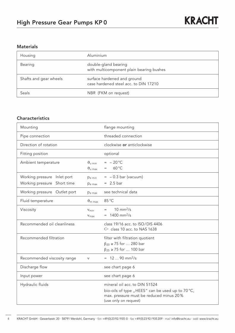
Materials
Housing Aluminium
Bearing double-gland bearing with multicomponent plain bearing bushes
Shafts and gear wheels surface hardened and groundcase hardened steel acc. to DIN 17210
Seals NBR (FKM on request)
Characteristics
Mounting flange mounting
Pipe connection threaded connection
Direction of rotation clockwise or anticlockwise
Fitting position optional
Ambient temperature ϑu min = – 20 °Cϑu max = 60 °C
Working pressure Inlet port pe min = – 0.3 bar (vacuum)
Working pressure Short time pe max = 2.5 bar
Working pressure Outlet port pe max see technical data
Fluid temperature ϑm max 85 °C
Viscosity νmin = 10 mm2/sνmax = 1400 mm2/s
Recommended oil cleanliness class 19/16 acc. to ISO/DIS 4406➧➧ class 10 acc. to NAS 1638
Recommended filtration filter with filtration quotientβ20 ≥ 75 for … 280 barβ25 ≥ 75 for … 100 bar
Recommended viscosity range ν = 12 … 90 mm2/s
Discharge flow see chart page 6
Input power see chart page 6
Hydraulic fluids mineral oil acc. to DIN 51524
bio-oils of type „HEES“ can be used up to 70 °C,max. pressure must be reduced minus 20 %(use only on request)

KRACHT GmbH · Gewerbestr. 20 · 58791 Werdohl, Germany · fon +49(0)23 92/935-0 · fax +49(0)23 92/935 209 · mail [email protected] · web www.kracht.eu 5
High Pressure Gear Pumps KP 0
Calculation Formulas for Hydraulic Pumps
Characteristic data, formula signs, units1. Discharge flow / input flow Q l/min2. Pump / motor displacement Vg cm3/r3. Pressure p bar4. Speed n 1/min5. Torque M Nm6. Power P kW7. Total efficiency ηηtot —8. Volumetric efficiency ηηvol —9. Hydr./mech. efficiency ηηhm —
10. Flow velocity v m/s11. Pipe diameter d mm
GeneralQth = Vg · n, ηη tot = ηη vol · ηη hm
M = 9549 · P , v = 21.22 Q n d2
Approximate values for KRACHT products in the nominal working point
KP 0 ηtot ηvol
1 to 4 ≈ 0.75 ≈ 0.85
6 to 8 ≈ 0.90 ≈ 0.90
Cha
ract
eris
tic
dat
a fo
r:
Pow
erTo
rque
Volu
met
ric
flow Discharge flow Q =
Vg · n · ηvol
103
lmin
Drive torque M =p · Vg
20 · π · η hm[Nm]
Input power P = p · Q
600 · ηtot[kW]
Q
p
nMP
Pump
Nominal geom. max. Nominal Continuous Speedsize displace- pressure pressure working
ment pressure
Vg pmax pN pD nmax nmin
cm3/r bar bar bar 1/min 1/min
1 1.4 280 260 220 4000 700
2 1.9 280 260 220 4000 700
3 3.1 260 250 210 4000 700
4 4.4 260 250 210 4000 700
6 6.1 260 250 210 3000 700
8 7.9 200 180 160 3000 700
Technical Data
Maximum pressure = pressure peakNominal pressure pN < 6 s = 50 % EDSee time / pressure chartmax. permissible working cycles: 30 / minPressures as specified are applicable to ν ≥ 30 mm2/s
Time / pressure chart PPressure
Pmax
PNPD
0.1 1 2 t (s)Time

High Pressure Gear Pumps KP 0
KRACHT GmbH · Gewerbestr. 20 · 58791 Werdohl, Germany · fon +49(0)23 92/935-0 · fax +49(0)23 92/935 209 · mail [email protected] · web www.kracht.eu6
Discharge Flow and Required Input Power
Discharge flow Q in l/min at 34 mm2/sPressure p in bar
size 20 60 100 140 180 220 260
1 2.00 1.95 1.90 1.86 1.82 1.78 1.73
2 2.80 2.70 2.65 2.60 2.55 2.50 2.40
3 4.70 4.65 4.60 4.55 4.50 4.45 –
4 6.30 6.25 6.20 6.15 6.10 6.05 –
6 9.00 8.95 8.90 8.85 8.80 – –
8 11.750 11.600 11.500 11.450 11.400 – –
Discharge flow at n = 1495 1/min
Pressure p in bar
size 20 60 100 140 180 220 260
1 0.14 0.32 0.50 0.68 0.86 1.05 1.23
2 0.17 0.42 0.67 0.92 1.17 1.42 1.66
3 0.25 0.57 0.91 1.30 1.60 2.00 –
4 0.30 0.75 1.20 1.60 2.05 2.50 –
6 0.40 1.05 1.70 2.30 2.95 – –
8 0.50 1.30 2.10 3.05 3.90 – –
Required input power at n = 1495 1/min
Nominal
Nominal

KRACHT GmbH · Gewerbestr. 20 · 58791 Werdohl, Germany · fon +49(0)23 92/935-0 · fax +49(0)23 92/935 209 · mail [email protected] · web www.kracht.eu 7
High Pressure Gear Pumps KP 0
Type Key
Ordering example
KP 0/ 1 K 1 0 S M 0 A 8 M L 1
Seal1 NBR rotary shaft lip
type seal ϑ ≤ 85 °C
Type of gearingL Shaft and pin wheel made
of case-hardened steel
Code for materialsM Housing: aluminium alloy
with bearing bushes
Design serial no.8 (specified by KRACHT)
End coverA (standard type)
Second shaft end0 without
Shaft endM Taper 1 : 8
Housing side portsS Inlet and outlet port G 3⁄8 Vg 1– 4
G 1⁄2 Vg 6 – 8
Direction of rotation1 clockwise2 anticlockwise
Outboard flanges or bearing resp.0 without
Flange mounting coverK 4 bolt rectangular flange
LA = 52.4 / 72; Ø z = 25.4
Size 0
Produc name
Nominal displacement1, 2, 3, 4, 6, 8
Possible on request: – Multiple pump combinations– Motors– Other shaft and flange types– FKM rotary shaft lip typ seals (on request)

High Pressure Gear Pumps KP 0
KRACHT GmbH · Gewerbestr. 20 · 58791 Werdohl, Germany · fon +49(0)23 92/935-0 · fax +49(0)23 92/935 209 · mail [email protected] · web www.kracht.eu8
K-Flange, Tapered Shaft End
Ordering example:
KP 0/1 K10S M0A 8ML1
Nominal1 2 3 4 6 8displacement
A 68.6 68.6 68.6 75.3 86.0 86.0
B 33.4 33.4 33.4 36.7 42.0 42.0
C 3⁄8’’ BSP 1⁄2’’ BSP
Weight in kg 0.9 0.95 0.95 1.05 1.2 1.2
F
Ø B
Ø A
Ø D
Ø K
L
Ø C
N
P
The direction of rotation asrepresented is clockwise In case of anticlockwise rotation the inlet and outlet ports are opposite
Shaft end: Taper 1:8
Bell housing with ventilation or leakage hole on request
Bell Housing
C
2.4 h9p9
5.5
Ø 8.1
71.925
.4f8
Ø 1
0
M 6
B
14 19.5
15
A 29
68.5
52.4
33.5
86.511
MotorA B C D F K L N P
Bell housingCoupling sizesize Weight in kg
71 160 110 130 110 7 9 70 13 M8 0.5 RA19/24-K16/10-Z25/14
80 200 130 165 145 7 11 90 16 M10 0.8 RA19/24-K25/10-Z25/19
90 200 130 165 145 7 11 90 16 M10 0.8 RA19/24-K16/10-Z25/24
100/112 250 180 215 190 7 14 110 18 M12 2.0 RA24/28-K16/10-Z50/28
Inlet portOutlet port
Taper 1 : 8
High Pressure Gear Pumps KP 0
KRACHT GmbH · Gewerbestr. 20 · 58791 Werdohl, Germany · fon +49(0)23 92/935-0 · fax +49(0)23 92/935 209 · mail [email protected] · web www.kracht.eu 9
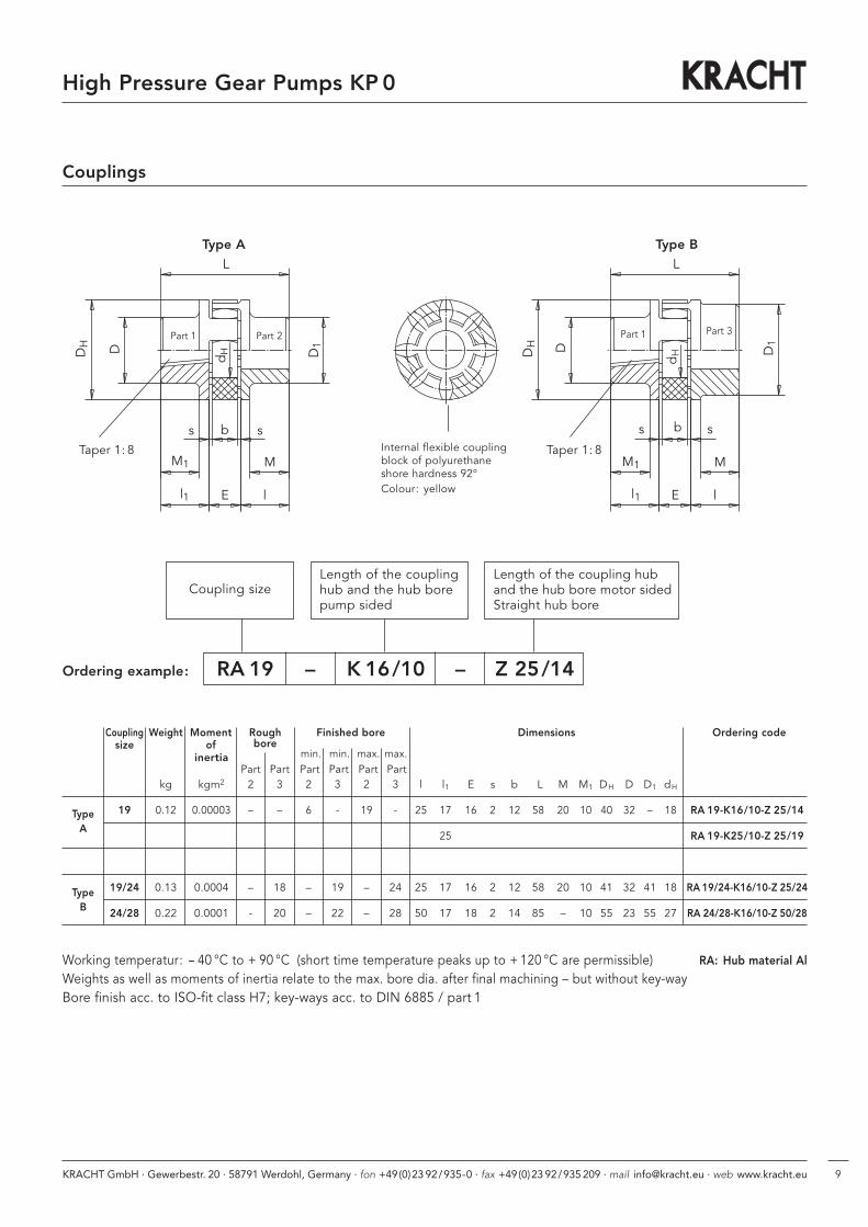
Coupling Weight Moment Rough Dimensions Ordering codesize of bore
min. min. max. max.inertiaPart Part Part Part Part Part
kg kgm2 2 3 2 3 2 3 l l1 E s b L M M1 DH D D1 dH
19 0.12 0.00003 – – 6 - 19 - 25 17 16 2 12 58 20 10 40 32 – 18 RA 19-K16/10-Z 25/14
25 RA 19-K25/10-Z 25/19
19/24 0.13 0.0004 – 18 – 19 – 24 25 17 16 2 12 58 20 10 41 32 41 18 RA 19/24-K16/10-Z 25/24
24/28 0.22 0.0001 - 20 – 22 – 28 50 17 18 2 14 85 – 10 55 23 55 27 RA 24/28-K16/10-Z 50/28
Couplings
b
dH
ss
E ll1
MM1
D1
DH D
L
b
dH
lEl1
M1
s
M
s
D1
L
DH D
Internal flexible coupling block of polyurethaneshore hardness 92°Colour: yellow
Taper 1: 8
Type A Type B
Part 1 Part 2 Part 1 Part 3
RA 19 – K 16/10 – Z 25/14
Coupling sizeLength of the couplinghub and the hub borepump sided
Length of the coupling huband the hub bore motor sidedStraight hub bore
Ordering example:
Taper 1: 8
Finished bore
Working temperatur: -- 40 °C to + 90 °C (short time temperature peaks up to + 120 °C are permissible) RA: Hub material Al
Weights as well as moments of inertia relate to the max. bore dia. after final machining – but without key-wayBore finish acc. to ISO-fit class H7; key-ways acc. to DIN 6885 / part 1
TypeA
TypeB
KRACHT GmbH · Gewerbestr. 20 · 58791 Werdohl, Germany · fon +49(0)23 92/935-0 · fax +49(0)23 92/935 209 · mail [email protected] · web www.kracht.eu10
High Pressure Gear Pumps KP 0
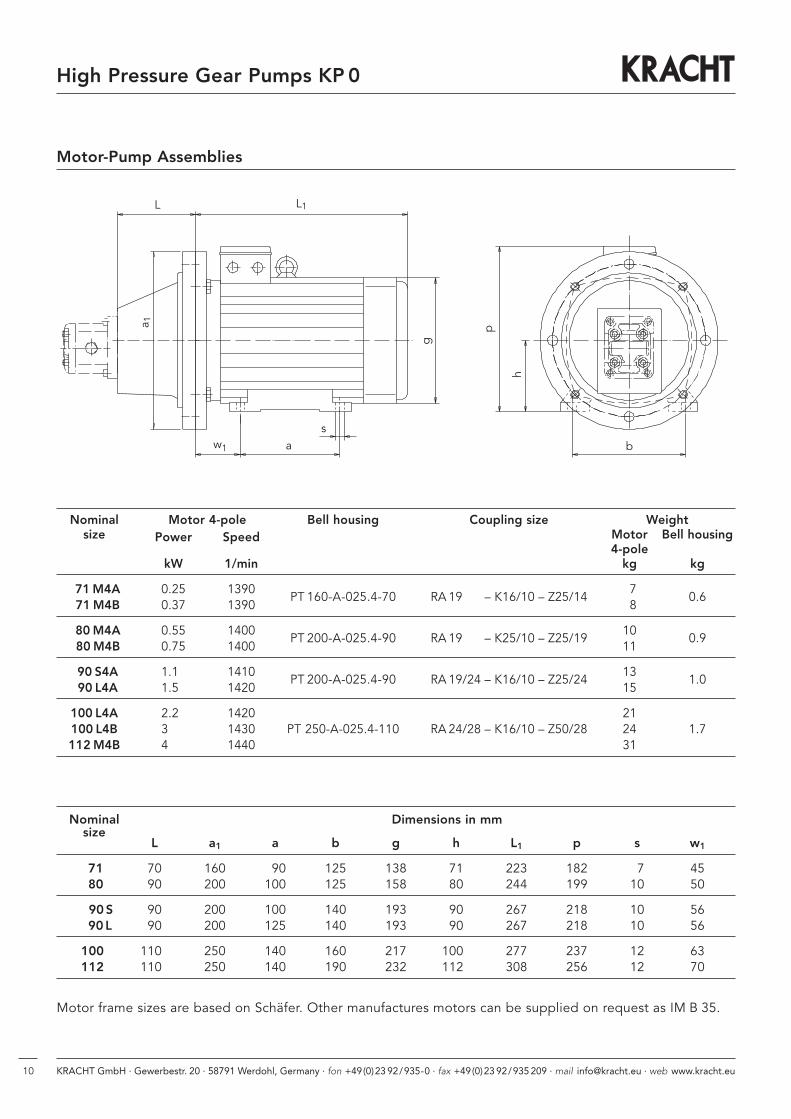
Motor-Pump Assemblies
L1L
a 1
w1 as
g
p
h
b
Nominal Dimensions in mmsize
L a1 a b g h L1 p s w1
71 70 160 90 125 138 71 223 182 7 4580 90 200 100 125 158 80 244 199 10 50
90 S 90 200 100 140 193 90 267 218 10 5690 L 90 200 125 140 193 90 267 218 10 56
100 1100 250 140 160 217 1000 277 237 12 63112 1100 250 140 190 232 1120 308 256 12 70
Motor frame sizes are based on Schäfer. Other manufactures motors can be supplied on request as IM B 35.
Nominal Motor 4-pole Bell housing Coupling size Weightsize Power Speed Motor Bell housing
4-polekW 1/min kg kg
71 M4A 0.25 1390PT 160-A-025.4-70 RA 19/24 – K16/10 – Z25/14
70.6
71 M4B 0.37 1390 8
80 M4A 0.55 1400PT 200-A-025.4-90 RA 19/24 – K25/10 – Z25/19
100.9
80 M4B 0.75 1400 11
90 S4A 1.10 1410PT 200-A-025.4-90 RA 19/24 – K16/10 – Z25/24
131.0
90 L4A 1.50 1420 15
100 L4A 2.20 1420 21100 L4B 3.00 1430 PT 250-A-025.4-110 RA 24/28 – K16/10 – Z50/28 24 1.7112 M4B 4,00 1440 31

KRACHT GmbH · Gewerbestr. 20 · 58791 Werdohl, Germany · fon +49(0)23 92/935-0 · fax +49(0)23 92/935 209 · mail [email protected] · web www.kracht.eu 11
High Pressure Gear Pumps KP 0
Note

KRACHT GmbH · Gewerbestraße 20 · 58791 Werdohl, Germany · fon +49 (0) 23 92 / 935-0 · fax +49 (0) 23 92 / 935 209
mail [email protected] · web www.kracht.eu
KP 0 / GB /05.10
Transfer PumpsTransfer pumps for lubricating oil supply equipment, low pressure filling and feed systems, dosing and mixing systems.
Mobile HydraulicsSingle and multistage high pressure gear pumps, hydraulic motors and valves for construction machinery, vehicle-mounted machines.
Flow MeasurementGear and turbine flow meters and electronics for volume and flow metering technology in hydraulics, processing and laquering technology.
Industrial Hydraulics /Test Bench ConstructionCetop directional control and proportional valves, hydraulic cylinders, pressure, quantity and stop valves for pipe and slab construction, hydraulic accessories for industrial hydraulics (mobile and stationary use).
Technology Test benches / Fluid Test benches.
Product Portfolio


