
ExcellentFinished Wall
HighSquareness
High efficient Endmills
MEC series

Large
Small
LowVf(mm/min)
ap(m
m)
High
MECHtype
heavy milling
generalMECtype
MECXtype small machines
Long cutting edge enable high efficiency machining
■MEC endmill series lineup
MECHtype Heavy milling and High efficient machining
■Advantages1.Improved Chip Evacuation2.Maximum Machining Efficiency3.Low Cutting Force4.Reduced chattering
Forheavy milling
Competitor A
MECH
A flat-cut flute provides excellent chip evacuation
Work Material :SS400Vc = 120 m/minap×ae=40mm×10mm,fz = 0.12mm/tMECH032-S32-11-5-4T
Noched inserts lower cutting force, reduce chattering and maximize efficiency
Notched insert breaks chips into small pieces
●Variety of MEC endmill series
1

● MECH applicable inserts
Description
Insert Grades
No. of nicks
2-Notched 3-Notched
BDMT11T3 typePR830 PR905
BDMT11T308ER-N2 ● ● 2
BDMT11T308ER-N3 ● ● 3
3-Notched 4-Notched
BDMT1704 typeBDMT170408ER-N3 ● ● 3
BDMT170408ER-N4 ● ● 4
● Low cutting force
15
10
5
0.080.06 0.1 0.15 0.2
Recommended cutting range
Cutting range
Wid
th o
f C
ut a
e(m
m)
Feed per Tooth fz(mm/t)
Comp. A Comp. B
MECHtype
5000
4000
3000
2000
1000
0MECHtype Comp. A Comp. B
3,5803,950
4,660C
uttin
g F
orc
e (N
)
MECH type
● Reduced chattering•Comparison of surface wallNotched insert lowers and disperses cutting force, and enables high feed rates by reducing Chattering
Work Material:S50CVc = 120 m/minap×ae = 40 mm×5~13 mmfz = 0.06 ~ 0.2 mm/tMECH032-S32-11-5-4T
Work Material:S50CVc = 120 m/minap×ae = 40mm×10 mmfz = 0.1mm/tMECH032-S32-11-5-4T
(Internal evaluation)
Comp.A
Work Material:S50CVc=120m/minfz=0.12mm/tap×ae=40×7mm
(Internal evaluation)
MECH Conventional type
•Cutting Force (principal force)•Low Cutting Force due to Notched Inserts
2

cutt
ing
dep
th (a
p)
feed per tooth (fz)
ap=3(mm)
fz=0.1mm/t
JSJS JTJT
Large
Small
LargeSmall
MECtype High efficient endmill
■Advantages
1.Low cutting force and sharp cutting performance
2.Perfect 90°shoulders, and smooth surface of shoulder wall
3.An extensive grade lineup applicable to a wide range of work materials, such as steel, stainless steel, cast iron and aluminum
Higher Rigidity & Durability
… Thicker Insert Seat & Larger Chip Pocket Radius
Higher Body Durability
…High Hardness Silver Coating
Air Hole (for Shanks of ø16mm and over)
High Strength & Long Tool Life
…PVD Coating
Low Cutting Force & Sharp Cutting Performance
…High Rake Angle (A.R. Max.+23°)
Better Chip Evacuation
…Large Chip Pocket
& Specific Chipbreaker
23°
Thicker Insert Seat Larger Chip Pocket Radius
● Excellent Shoulder Wall Surface FinishesSmoothly finished shoulder wall and high squareness at shouldering with multipul passes
● Perfect 90° Shoulders
MEC tyep ENDMILL Comp.A
13µm 18µm 29µm
Comp.B
90°
Cutting Dia. 20mm / S50CVc=120m/min,ap×ae=5×10mmfz=0.1mm/t, Dry(with compressed air)
(Internal evaluation)
MECXtype High efficient and low cutting foce endmill
■Advantages1.Extra-fine pitch increases machining
efficiency cutter that holds multiple inserts
2.Ideal for lower horsepower machines: low resistance and high strength design
3.Covers a broad range of applications with the multi-purpose JT chipbreaker and the low resistance JS chipbreaker
Recommended forsmall machines
● Chipbreaker Lineup
Low resistance JS ChipbreakerGeneral JT Chipbreaker
● Chipbreaker Application Chart
(Internal evaluation)
3
For Steel
Finishing Roughing
WorkMaterial Carbon Steel•Alloy Steel
CuttingRange
P01 P10 P20 P30Classification
ApplicableRange
For Stainless
Finishing Roughing
WorkMaterial Stainless
CuttingRange
M01 M10 M20 M30Classification
ApplicableRange
For Cast Iron
Finishing Roughing
WorkMaterial Cast Iron
CuttingRange
K01 K10 K20 K30Classification
ApplicableRange
Micro grain carbide substrate
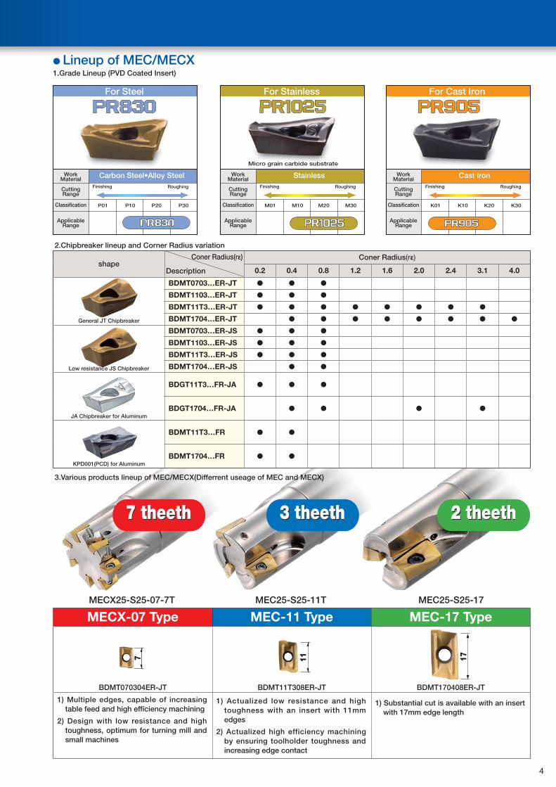
● Lineup of MEC/MECX1.Grade Lineup (PVD Coated Insert)
2.Chipbreaker lineup and Corner Radius variation
shapeConer Radius(rε)
Description
Coner Radius(rε)
0.2 0.4 0.8 1.2 1.6 2.0 2.4 3.1 4.0
General JT Chipbreaker
BDMT0703…ER-JT ● ● ●
BDMT1103…ER-JT ● ● ●
BDMT11T3…ER-JT ● ● ● ● ● ● ● ●
BDMT1704…ER-JT ● ● ● ● ● ● ● ●
Low resistance JS Chipbreaker
BDMT0703…ER-JS ● ● ●
BDMT1103…ER-JS ● ● ●
BDMT11T3…ER-JS ● ● ●
BDMT1704…ER-JS ● ●
JA Chipbreaker for Aluminum
BDGT11T3…FR-JA ● ● ●
BDGT1704…FR-JA ● ● ● ●
KPD001(PCD) for Aluminum
BDMT11T3…FR ● ●
BDMT1704…FR ● ●
3.Various products lineup of MEC/MECX(Differrent useage of MEC and MECX)
MECX-07 Type MEC-11 Type MEC-17 Type
BDMT070304ER-JT BDMT11T308ER-JT BDMT170408ER-JT
1) Multiple edges, capable of increasing table feed and high efficiency machining
2) Design with low resistance and high toughness, optimum for turning mill and small machines
1) Actualized low resistance and high toughness with an insert with 11mm edges
2) Actualized high efficiency machining by ensuring toolholder toughness and increasing edge contact
1) Substantial cut is available with an insert with 17mm edge length
17117
3 theeth 2 theeth
MECX25-S25-07-7T MEC25-S25-11T MEC25-S25-17
7 theeth
Higher Body Durability
…High Hardness Silver Coating
4
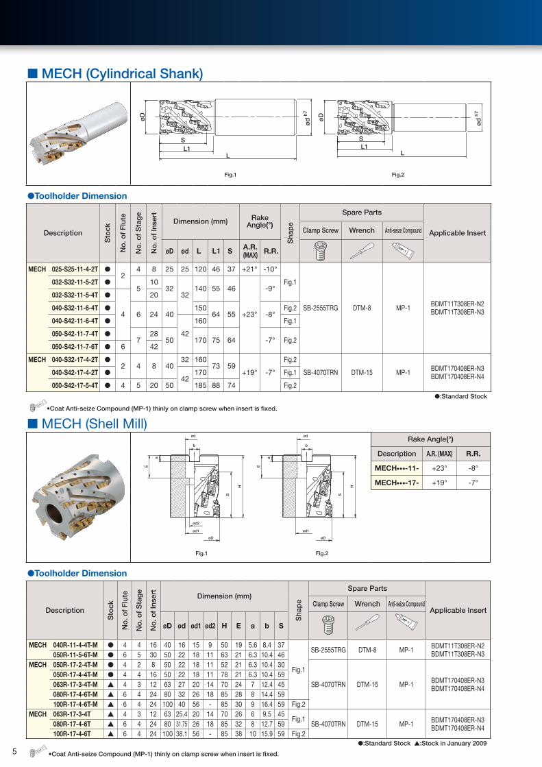
■ MECH (Cylindrical Shank)
ød
h7
LL1
Sø
D
ød
h7
øD
LL1
S
Fig.1 Fig.2
●Toolholder Dimension
Description
Sto
ck
No
. of
Flu
te
No
. of
Sta
ge
No
. of
Inse
rt
Dimension (mm) Rake Angle(°)
Sha
pe
Spare Parts
Applicable InsertClamp Screw Wrench Anti-seize Compound
øD ød L L1 S A.R. (MAX) R.R.
MP-1
MECH 025-S25-11-4-2T ●2
4 8 25 25 120 46 37 +21° -10°
Fig.1
SB-2555TRG DTM-8 MP-1 BDMT11T308ER-N2 BDMT11T308ER-N3
032-S32-11-5-2T ●5
1032
32140 55 46
+23°
-9°032-S32-11-5-4T ●
4
20
040-S32-11-6-4T ●6 24 40
15064 55 -8°
Fig.2
040-S42-11-6-4T ●
42
160 Fig.1
050-S42-11-7-4T ●7
2850 170 75 64 -7° Fig.2
050-S42-11-7-6T ● 6 42
MECH 040-S32-17-4-2T ●2 4 8 40
32 16073 59
+19° -7°
Fig.2
SB-4070TRN DTM-15 MP-1 BDMT170408ER-N3 BDMT170408ER-N4040-S42-17-4-2T ●
42170 Fig.1
050-S42-17-5-4T ● 4 5 20 50 185 88 74 Fig.2
●:Standard StockMP-1
•Coat Anti-seize Compound (MP-1) thinly on clamp screw when insert is fixed.
■ MECH (Shell Mill)
S
H
b
a
E
ød
ød2
ød1
øD
S
H
b
a
E
ød
ød1
øD
Rake Angle(°)
Description A.R. (MAX) R.R.
MECH● ● ●-11- +23° -8°
MECH● ● ●-17- +19° -7°
Fig.1 Fig.2
●Toolholder Dimension
Description
Sto
ck
No
. of
Flu
te
No
. of
Sta
ge
No
. of
Inse
rt Dimension (mm)
Sha
pe
Spare Parts
Applicable InsertClamp Screw Wrench Anti-seize Compound
øD ød ød1 ød2 H E a b SMP-1
MECH 040R-11-4-4T-M ● 4 4 16 40 16 15 9 50 19 5.6 8.4 37
Fig.1
SB-2555TRG DTM-8 MP-1 BDMT11T308ER-N2BDMT11T308ER-N3050R-11-5-6T-M ● 6 5 30 50 22 18 11 63 21 6.3 10.4 46
MECH 050R-17-2-4T-M ● 4 2 8 50 22 18 11 52 21 6.3 10.4 30
SB-4070TRN DTM-15 MP-1 BDMT170408ER-N3 BDMT170408ER-N4
050R-17-4-4T-M ● 4 4 16 50 22 18 11 78 21 6.3 10.4 59063R-17-3-4T-M ▲ 4 3 12 63 27 20 14 70 24 7 12.4 45080R-17-4-6T-M ▲ 6 4 24 80 32 26 18 85 28 8 14.4 59100R-17-4-6T-M ▲ 6 4 24 100 40 56 - 85 30 9 16.4 59 Fig.2
MECH 063R-17-3-4T ▲ 4 3 12 63 25.4 20 14 70 26 6 9.5 45Fig.1
SB-4070TRN DTM-15 MP-1 BDMT170408ER-N3 BDMT170408ER-N4080R-17-4-6T ▲ 6 4 24 80 31.75 26 18 85 32 8 12.7 59
100R-17-4-6T ▲ 6 4 24 100 38.1 56 - 85 38 10 15.9 59 Fig.2●:Standard Stock ▲:Stock in January 2009
MP-1
•Coat Anti-seize Compound (MP-1) thinly on clamp screw when insert is fixed. 5

■ MECH-BT50 (Integral Arbor Type)
BT-50 shankS
0°
ø10
0
38
101.8L
øD
Rake Angle(°)
Description A.R. (MAX) R.R.
MECH● ● ●-11- +23° -7°
MECH● ● ●-17- +19° -7°
Fig.1
●Toolholder Dimension
Description
Sto
ck
No
. of
Flu
te
No
. of
Sta
ge
No
. of
Inse
rt Dimension (mm)
Rake Angle(°)
Sha
pe
Spare Parts
Applicable InsertClamp Screw Wrench Anti-seize Compound
øD L S A.R. (MAX) R.R.
MP-1
MECH 050R11-8-4T-BT50 ● 4 8 32 50 143 73 +23° -7°
Fig.1
SB-2555TRG DTM-8 MP-1 BDMT11T308ER-N2 BDMT11T308ER-N3
MECH 050R17-7-4T-BT50 ●
47
28
50
173 104 +19° -7° SB-4070TRN DTM-15 MP-1 BDMT170408ER-N3 BDMT170408ER-N4
063R17-7-4T-BT50 ▲ 63
080R17-7-4T-BT50 ▲ 80
100R17-7-6T-BT50 ▲ 6 42 100
●:Standard Stock ▲:Stock in January 2009MP-1
•Coat Anti-seize Compound (MP-1) thinly on clamp screw when insert is fixed.
■ Applicable Insert
Shape
Right-hand Shown
Description
Dimension(mm) Angle(°) Stock Grades
Applicable Toolholder
PVD Coated
A T ød W rε α β PR830 PR905
2-Notched
rε
(10°)A
W ød
α
T
β
BDMT 11T308ER-N2 6.7 3.80 2.8 11.0 0.8 18° 13° ● ●
MECH•••-11-
3-Notched
A
W ød
α
T
β
rε
(10°) BDMT 11T308ER-N3 6.7 3.80 2.8 11.0 0.8 18° 13° ● ●
3-Notched β
rε
W
A
α
T
ød
(10°) BDMT 170408ER-N3 9.6 4.90 4.4 17.0 0.8 18° 13° ● ●
MECH•••-17-
4-Notched
α
TA
W
rε
ød
β
(10°) BDMT 170408ER-N4 9.6 4.90 4.4 17.0 0.8 18° 13° ● ●
Inserts are sold in 10 piece boxes. ●:Standard Stock
■ Recommended Cutting Condition
Workpiece Material Feed Rate(mm/t)
Insert Grade(Cutting Speed Vc:m/min)
PVD Coated
PR830 PR905
Carbon Steel (SxxC) 0.08~0.1~0.15 100~180 -
Alloy Steel (SCM) 0.08~0.1~0.15 100~180 -
Die Steel (SKD/NAK) 0.08~0.1~0.15 100~150 -
Gray Cast Iron (FC) 0.08~0.1~0.15 - 100~180
Nodular Cast Iron (FCD) 0.08~0.1~0.15 - 100~150 6

● MECH Endmill Type
Cutting Dia.
DescriptionOverhang
Length:A(mm)
ø25 MECH025-S25-11-4-2T 48
ø32 MECH032-S32-11-5-2T
57 MECH032-S32-11-5-4T
ø40 MECH040-S32-11-6-4T
65 MECH040-S42-11-6-4T
ø50 MECH050-S42-11-7-4T
76 MECH050-S42-11-7-6T
ø40 MECH040-S32-17-4-2T
74 MECH040-S42-17-4-2T
ø50 MECH050-S42-17-5-4T 89
Shape
A
2 Flute Type (Work Material:S50C)
Description
■Shouldering ■Grooving
øD
ap
Cutting Speed :Vc=100~180m/minFeed :fz=0.08~0.15mm/t
Cutting Speed :Vc=100~120m/minFeed :fz=0.08~0.12mm/t
MECH025-S25-11-4-2T
ap(mm)
100
10
20
30
40
20 30
D.O
.C.
Width of Cut ae(mm)
ap(mm)
0.08 0.10
10
20
30
40
0.12
D.O
.C.
Feed Rate fz(mm/t)
MECH032-S32-11-5-2T
ap(mm)
100
20
10
30
40
50
20 30
D.O
.C.
Width of Cut ae(mm)
ap(mm)
0.08 0.10
20
10
30
40
50
0.12
D.O
.C.
Feed Rate fz(mm/t)
MECH040-S32-17-4-2TMECH040-S42-17-4-2T
ap(mm)
100
30
20
10
40
50
60
20 30 40
D.O
.C.
Width of Cut ae(mm)
ap(mm)
0.08 0.10
30
20
10
40
50
60
0.12
D.O
.C.
Feed Rate fz(mm/t)
4 Flute / 6 Flute Type
MECH032-S32-11-5-4T
ap(mm)
100
20
10
30
40
50
20 30
D.O
.C.
Width of Cut ae(mm)
MECH040-S32-11-6-4TMECH040-S42-11-6-4T
ap(mm)
100
30
20
10
40
50
60
20 30
D.O
.C.
Width of Cut ae(mm)
MECH050-S42-11-7-4T
ap(mm)
100
20
40
60
20 30
D.O
.C.
Width of Cut ae(mm)
MECH050-S42-11-7-6T
ap(mm)
100
20
40
60
20 30
D.O
.C.
Width of Cut ae(mm)
MECH050-S42-17-5-4T
ap(mm)
100
40
20
60
80
20 30
D.O
.C.
Width of Cut ae(mm)
4 Flute / 6 Flute Type are not recommended for grooving.
■Cutting Performance (Tested Machine:Machining center equivalent to AC15/18.5kw)
7
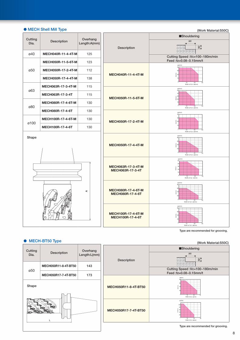
● MECH Shell Mill Type
Cutting Dia.
DescriptionOverhang
Length:A(mm)
ø40 MECH040R-11-4-4T-M 125
ø50
MECH050R-11-5-6T-M 123
MECH050R-17-2-4T-M 112
MECH050R-17-4-4T-M 138
ø63MECH063R-17-3-4T-M 115
MECH063R-17-3-4T 115
ø80MECH080R-17-4-6T-M 130
MECH080R-17-4-6T 130
ø100MECH100R-17-4-6T-M 130
MECH100R-17-4-6T 130
Shape
A
● MECH-BT50 Type
Cutting Dia.
DescriptionOverhang
Length:L(mm)
ø50MECH050R11-8-4T-BT50 143
MECH050R17-7-4T-BT50 173
Shape
L
(Work Material:S50C)
Description
■Shouldering
Cutting Speed :Vc=100~180m/minFeed :fz=0.08~0.15mm/t
MECH040R-11-4-4T-M
ap(mm)
100
10
20
30
40
20 30
D.O
.C.
Width of Cut ae(mm)
MECH050R-11-5-6T-M
ap(mm)
0
20
10
30
40
50
10 20 30
D.O
.C.
Width of Cut ae(mm)
MECH050R-17-2-4T-M
ap(mm)
100
20
10
30
40
20 30
D.O
.C.
Width of Cut ae(mm)
MECH050R-17-4-4T-M
ap(mm)
100
40
20
60
80
20 30
D.O
.C.
Width of Cut ae(mm)
MECH063R-17-3-4T-MMECH063R-17-3-4T
ap(mm)
0
20
10
30
40
50
10 20 30 D
.O.C
.
Width of Cut ae(mm)
MECH080R-17-4-6T-MMECH080R-17-4-6T
ap(mm)
100
40
20
60
80
20 30
D.O
.C.
Width of Cut ae(mm)
MECH100R-17-4-6T-MMECH100R-17-4-6T
ap(mm)
100
40
20
60
80
20 30
D.O
.C.
Width of Cut ae(mm)
Type are recommended for grooving.
(Work Material:S50C)
Description
■Shouldering
Cutting Speed :Vc=100~180m/minFeed :fz=0.08~0.15mm/t
MECH050R11-8-4T-BT50
ap(mm)
100
40
20
60
80
20 30
D.O
.C.
Width of Cut ae(mm)
MECH050R17-7-4T-BT50
ap(mm)
0
60
40
20
80
100
10 20 30
D.O
.C.
Width of Cut ae(mm)
Type are recommended for grooving.
8
Chip removal Q=170cc/min.Chip removal Q=115cc/min.
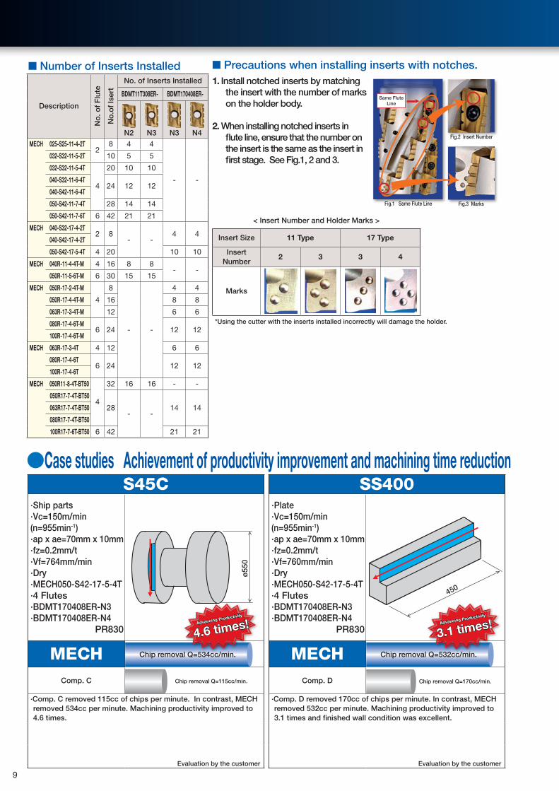
■ Precautions when installing inserts with notches. 1. Install notched inserts by matching
the insert with the number of marks on the holder body.
2. When installing notched inserts in flute line, ensure that the number on the insert is the same as the insert in first stage. See Fig.1, 2 and 3.
< Insert Number and Holder Marks >
Insert Size 11 Type 17 Type
Insert Number
2 3 3 4
Marks
*Using the cutter with the inserts installed incorrectly will damage the holder.
Fig.1 Same Flute Line
Fig.2 Insert Number
Fig.3 Marks
Same Flute Line
●Case studies Achievement of productivity improvement and machining time reduction
Chip removal Q=534cc/min.
S45C∙Ship parts∙Vc=150m/min(n=955min-1)∙ap x ae=70mm x 10mm∙fz=0.2mm/t∙Vf=764mm/min∙Dry∙MECH050-S42-17-5-4T∙4 Flutes∙BDMT170408ER-N3∙BDMT170408ER-N4
PR830
ø55
0
MECHComp. C
∙Comp. C removed 115cc of chips per minute. In contrast, MECH removed 534cc per minute. Machining productivity improved to 4.6 times.
Evaluation by the customer
Chip removal Q=532cc/min.
SS400∙Plate∙Vc=150m/min(n=955min-1)∙ap x ae=70mm x 10mm∙fz=0.2mm/t∙Vf=760mm/min∙Dry∙MECH050-S42-17-5-4T∙4 Flutes∙BDMT170408ER-N3∙BDMT170408ER-N4
PR830
450
MECHComp. D
∙Comp. D removed 170cc of chips per minute. In contrast, MECH removed 532cc per minute. Machining productivity improved to 3.1 times and finished wall condition was excellent.
Evaluation by the customer
Advancing Productivity
4.6 times! Advancing Productivity
3.1 times!
■ Number of Inserts Installed
DescriptionN
o. o
f F
lute
No
.of
Iser
t
No. of Inserts Installed
BDMT11T308ER- BDMT170408ER-
N2 N3 N3 N4
MECH 025-S25-11-4-2T2
8 4 4
- -
032-S32-11-5-2T 10 5 5
032-S32-11-5-4T
4
20 10 10
040-S32-11-6-4T24 12 12
040-S42-11-6-4T
050-S42-11-7-4T 28 14 14
050-S42-11-7-6T 6 42 21 21
MECH 040-S32-17-4-2T2 8
- -4 4
040-S42-17-4-2T
050-S42-17-5-4T 4 20 10 10
MECH 040R-11-4-4T-M 4 16 8 8- -
050R-11-5-6T-M 6 30 15 15
MECH 050R-17-2-4T-M
4
8
- -
4 4
050R-17-4-4T-M 16 8 8
063R-17-3-4T-M 12 6 6
080R-17-4-6T-M6 24 12 12
100R-17-4-6T-M
MECH 063R-17-3-4T 4 12 6 6
080R-17-4-6T6 24 12 12
100R-17-4-6T
MECH 050R11-8-4T-BT50
4
32 16 16 - -
050R17-7-4T-BT50
28- -
14 14063R17-7-4T-BT50
080R17-7-4T-BT50
100R17-7-6T-BT50 6 42 21 21
9

■MEC Endmill
øD +0-0.2
Sℓ
L
Fig.2
ødn7
Sℓ
L
øD +0-0.2
Fig.4
ødn7
Fig.1
øD +0-0.2
Sℓ
L
ødn7
Fig.3
Sℓ
L
øD +0-0.2
ødn7
●Toolholder Dimension
Description
Sto
ck
No.o
f Ins
ert
Dimension(mm)Rake
Angle(°)
Cool
ant H
ole
Sha
pe
Spare Parts
ApplicableInsert
Max. Revolution(min-1)
Clamp Screw Wrench
øD ød L ℓ S A.R. (MAX) R.R.
Sta
ndar
d S
hank
MEC 10-S10-11 ●
1
1010
80
17
10
+10° -24°No Fig.1
SB-2545TR DTM-8 BDMT1103
54,80010-S16-11 ● 16 Yes Fig.212-S10-11 ●
1210
20 +12°
-21°No Fig.1
50,80012-S12-11 ● 1212-S16-11 ● 16 Yes Fig.213-S12-11 ● 13
12-19°
No Fig.149,200
14-S12-11 ●14 47,700
14-S16-11 ● 16 Yes Fig.2MEC 16-S12-11T ●
216 12
10023
10
+18°-14° No Fig.1
SB-2555TRG DTM-8BDMT11T3BDGT11T3
43,75017-S16-11T ● 17
16-13°
Yes Fig.3
43,50018-S16-11T ● 18 +19° 43,00019-S16-11T ●
3
19
26+20°
-10°42,000
20-S16-11T ● 20110
41,00021-S20-11T ● 21
20
-9° 40,30022-S20-11T ● 22
+21° -10°39,600
24-S20-11T ● 24120 29
38,20025-S20-11T ● 25 37,50028-S25-11T ● 28
25+22°
-9°35,800
30-S25-11T ●4
30130 32
+23°
34,80032-S25-11T ● 32 33,90040-S32-11T ●
540
32 150 50-8° 30,000
50-S32-11T ● 50 -7° 22,500
Same
Shank
Size MEC 16-S16-11T ● 2 16 16 100
3010
+18° -14°
Yes Fig.4 SB-2555TRG DTM-8BDMT11T3BDGT11T3
43,75020-S20-11T ●
320 20 110 +20°
-10°41,000
25-S25-11T ● 25 25 120 32 +21° 37,50032-S32-11T ● 4 32 32 130 40 +23° -9° 33,900
Long
Sha
nk
MEC 20-S18-170-11T ●
2
2018 170 30
10
+20°
-10°
Yes
Fig.3
SB-2555TRG DTM-8BDMT11T3BDGT11T3
41,00020-S20-140-11T ●
20140
60 Fig.420-S20-170-11T ●
17022-S20-170-11T ● 22 30
+21°Fig.3
39,60025-S23-210-11T ●
2523 210 32
37,50025-S25-160-11T ●
25160
60 Fig.425-S25-210-11T ●
21028-S25-210-11T ● 28 32 +22°
-9°
Fig.335,800
32-S30-250-11T ●
3230 250 40
+23°33,90032-S32-200-11T ●
32
20065 Fig.4
32-S32-250-11T ●250
35-S32-250-11T ● 35 40Fig.3
32,60040-S32-240-11T ● 40 240 65 -8° 30,000
Sta
ndar
d MEC 25-S20-17 ● 2 25 20 120 36
15.7
+16° -11°
Yes Fig.3 SB-4070TRN DTM-15
BDMT1704BDGT1704
35,00032-S25-17 ● 3 32 25 130 40 +17°
-7°30,000
40-S32-17 ●4
4032 150 50 +19°
25,00050-S32-17 ● 50 17,000
Same S
ize MEC 25-S25-17 ● 2 25 25 120 3615.7
+16° -11°Yes Fig.4 SB-4070TRN DTM-15
35,00032-S32-17 ● 3 32 32 130 40 +17° -7° 30,000
Long
MEC 25-S25-160-17 ●
2
2525
16060
15.7
+16° -11°
Yes
Fig.4
SB-4070TRN DTM-15
35,00025-S25-210-17 ●
21028-S25-210-17 ● 28 36 Fig.3 32,50032-S32-200-17 ●
3232
20065
+17°-7°
Fig.4 30,00032-S32-250-17 ●
25035-S32-250-17 ● 35 40
Fig.327,700
40-S32-240-17 ● 40 240 65 +19° 25,000●:Standard Stock
■Maximum RevolutionWhen running the endmill and cutter at the maximum revolution, the insert or holder may be damaged by centrifugal force. For more details, see "Warning" on page 12. 10

■ When using an insert with corner-radius 1.6mm or larger, additional processing may be necessary. Apply additional processing to the body corner according to the chart. If corner-radius is 1.2mm, additional processing is not needed.
*Round- shaped additional processing is recommended.When applying chamfer, do not cut away too much.
Body Corner Insert with LargeCorner-R(rε)
AdditionallyProcessed
Pre-processing Post-processing
Insert Corner-R(rε) Additional Processing Dimension (mm) to Body Corner
1.6R1.0
2.02.4 R1.23.1 R1.64.0 R2.5
●When using Center-through Air / Coolant /MistIf Center Through air (Coolant, Mist) is used, please use appropriate arbor and clamp with arbor bolt. (Table1)
●MEC's surface finish when shouldering with multiple passesIn order to obtain smoothly finished shoulder wall with multiple passes keep less than 5.5mm for 11T3 type and also keep less than 9mm for 1704 type.
Table1
Holder Description Arbor attachment Bolt (Attachment) Wrench
MEC040R••••-M HH8×25H LW-5(Double width 5mm)
MEC050R••••-M
MEC063R••••-MHH10×30H LW-6(Double width 6mm)
MEC063R••••
MEC080R••••HH12×35H LW-8(Double width 8mm)
MEC100R••••-N HH16×52H LW-12(Double width 12mm)
MEC125R•••• HF20×53H LW-14(Double width 14mm)
MEC160R•••• HF24×60H LW-17(Double width 17mm)
Wrench is not included. Purchase separately.
■Maximum RevolutionWhen running the endmill and cutter at the maximum revolution, the insert or holder may be damaged by centrifugal force. For more details, see "Warning" on page 12.
■MEC Face Mill
ød
ød2ød1 ød1
øD øD
Fig.1 Fig.2
bødb
0° 0°
aE
aE
HS
HS
0°
●Toolholder Dimension
Description
sto
ck
No.
of I
nser
t
Dimension(mm)
Cool
ant H
ole
Sha
pe
Wei
ght
(Kg)
Spare PartsMax.
Revolution(min-1)
Clamp Screw Wrench
øD ød ød1 ød2 H E a b S
Sta
ndar
d
MEC 040R-11-5T-M ● 5 40 16 14 8.540
20 5.5 8.5
10 YesFig.1
0.3
SB-2555TRG DTM-8
30,000 050R-11-5T-M ● 5 50
22 18 12 22 6.3 10.40.4 22,500
063R-11-6T-M ● 6 63 0.6 20,500 063R-11-6T ● 6 63
25.4 20 14 50 26 6 9.50.8 20,500
080R-11-7T ● 7 80 1.0 18,500 100R-11-9TN ● 9 100 31.75 26 17.6
6332 8 12.7 1.8 17,000
125R-11-11T ● 11 125 38.1 45 32 38 10 15.9 3.4 15,000 160R-11-14T ● 14 160 50.8 70 - 47 10 19.1 Fig.2 4.4 13,900
Fine
pitc
h MEC 050R-11-7T-M ● 7 5022 18 12 40 22 6.3 10.4
10 Yes Fig.1
0.4
SB-2555TRG DTM-8
22,500 063R-11-8T-M ● 8 63 0.6 20,500 063R-11-8T ● 8 63
25.4 20 14 50 26 6 9.50.8 20,500
080R-11-10T ● 10 80 1.0 18,500
Sta
ndar
d
MEC 040R-17-4T-M ● 4 40 16 14 8.540
20 5.5 8.5
15.7 YesFig.1
0.3
SB-4070TRN DTM-15
25,000 050R-17-4T-M ● 4 50
22 18 12 22 6.3 10.40.4 17,000
063R-17-5T-M ● 5 63 0.6 14,500 063R-17-5T ● 5 63
25.4 20 14 50 26 6 9.50.8 14,500
080R-17-6T ● 6 80 1.0 12,000 100R-17-7TN ● 7 100 31.75 26 17.6
6332 8 12.7 1.8 10,500
125R-17-9T ● 9 125 38.1 45 32 38 10 15.9 3.4 8,900 160R-17-12T ● 12 160 50.8 70 - 47 10 19.1 Fig.2 4.5 7,400
Fine
pitc
h
MEC 050R-17-5T-M ● 5 5022 18 12 40 22 6.3 10.4
15.7 Yes Fig.1
0.4
SB-4070TRN DTM-15
17,000 063R-17-6T-M ● 6 63 0.6 14,500 063R-17-6T ● 6 63
25.4 20 14 50 26 6 9.50.8 14,500
080R-17-8T ● 8 80 1.0 12,000 100R-17-9TN ● 9 100 31.75 26 17.6 63 32 8 12.7 1.8 10,500
●:Standard Stock
Rake Angle(°)
11 TypeA.R.(MAX): +23°R.R. : -7°
17 TypeA.R.(MAX): +19°R.R. : -7°
11

●Applicable InsertGuidance of usage choice Carbon Steel∙Alloy Steel ★
★:Roughing/First Choice
:Roughing/Second Choice■:Finishing/First Choice
:Finishing/Second Choice
(High Hardness material is applicable only under 45HRC)
Die Steel ★
Stainless steel ★
Gray cast Iron ★
Ductile cast Iron ★
Non Ferrous Iron ★ ■
Heat resistance part ★
Titanium Alloy ★ ■
Hardened Material
Description
Dimension (mm) Angle (°) Cermet PVD Coated Carbide PCDApplicableToolholder
A T ød W rε S α β
TN10
0M
PR83
0
PR10
25
PR90
5
GW25
KPD0
01
ød
A
rε
T
W
(10°) α
β
BDMT 110302ER-JT6.3 3.00 2.8 11.0
0.2
- 18° 15°
● ●
MEC··-…-11110304ER-JT 0.4 ● ●
110308ER-JT 0.8 ● ●
BDMT 11T302ER-JT
6.7 3.80 2.8 11.0
0.2
- 18° 13°
● ●
MEC··-…-11T MEC…R-11
11T304ER-JT 0.4 ● ●
11T308ER-JT 0.8 ● ●
11T312ER-JT 1.2 ● ●
11T316ER-JT 1.6 ● ●
11T320ER-JT 2.0 ● ●
11T324ER-JT 2.4 ● ●
11T331ER-JT 3.1 ● ●
BDMT 170404ER-JT
9.6 4.90 4.4 17.0
0.4
- 18° 13°
● ●
MEC··-…-17 MEC…R-17
170408ER-JT 0.8 ● ●
170412ER-JT 1.2 ● ●
170416ER-JT 1.6 ● ●
170420ER-JT 2.0 ● ●
170424ER-JT 2.4 ● ●
170431ER-JT 3.1 ● ●
170440ER-JT 4.0 ● ●
ød
A
rε
T
W
(10°) α
β
BDMT 110302ER-JS6.3 3.00 2.8 11.0
0.2
- 18° 15°
● ●
MEC··-…-11110304ER-JS 0.4 ● ●
110308ER-JS 0.8 ● ●
BDMT 11T302ER-JS6.7 3.80 2.8 11.0
0.2
- 18° 13°
● ●MEC··-…11TMEC…R-1111T304ER-JS 0.4 ● ●
11T308ER-JS 0.8 ● ●
BDMT 170404ER-JS9.6 4.90 4.4 17.0
0.4- 18° 13°
● ● MEC··-…-17 MEC…R-17170408ER-JS 0.8 ● ●
ød
A
rε
T
W
(10°) α
β
BDGT 11T302FR-JA6.7 3.80 2.8 11.0
0.2
- 18° 13°
●MEC··-…11TMEC…R-1111T304FR-JA 0.4 ●
11T308FR-JA 0.8 ●
BDGT 170404FR-JA
9.6 4.90 4.4 17.0
0.4
- 18° 13°
●
MEC··-…-17MEC…R-17
170408FR-JA 0.8 ●
170420FR-JA 2.0 ●
170431FR-JA 3.1 ●
α
β
ød
10°TA
WS
rε
BDMT 11T302FR6.7 3.80 2.8 11.0
0.23.6 18° 13°
● MEC··-…11TMEC…R-1111T304FR 0.4 ●
BDMT 170402FR9.6 4.90 4.4 17.0
0.24.4 18° 13°
● MEC··-…11TMEC…R-11170404FR 0.4 ●
*Chipbreaker Lineup: JT (general purpose), JS (low cutting force), JA (aluminum & non-ferrous) ●:Standard Stock
To avoid the significant hazard to you, we ask for your cooperation in carefully observing the following guidelines.
Warning about Maximum Revolution indicated on the Product1.If the tool is used over maximum recommended revolution the body of the tool may be broken by
inserts and clamp screws which may be dispersed by centrifugal force. 2.Machine within the recommended cutting conditions of the insert.3.When using at higher revolution (over 10,000min-1), refer to the table shown on the right to adjust
the balance by combining MEC and suitable arbor.
Max. Revolution
(min-1)
ISO 1940-1/8821(JIS B0905)
~20,000 G16~30,000 G6.330,000~ G2.5
Warning
12
Slant Milling•Helical Milling Vertical Milling
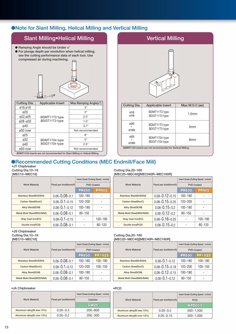
●Note for Slant Milling, Helical Milling and Vertical Milling
Cutting Dia. Applicable Insert Max.Ramping Angle(α°)ø16,ø18
BDMT11T3 typeBDGT11T3 type
3°
ø20 5°
ø22,ø25 2.5°
ø28~ø32 1.5°
ø40 0.7°
ø50 over Not recommended
ø25BDMT1704 typeBDGT1704 type
8°
ø32 5°
ø40 2.5°
ø50 over Not recommended
BDMT1103 inserts are not recommended for Slant Milling or Helical Milling.
● Ramping Angle should be Under α°● For plunge depth per revolution when helical milling,
see the cutting performance data of each tool. Use compressed air during machining.
Cutting Dia. Applicable Insert Max.W.O.C.(ae)
ø16ø18
BDMT11T3 typeBDGT11T3 type
1.5mm
ø20~
ø160
BDMT11T3 typeBDGT11T3 type
5mm
ø25~
ø160
BDMT1704 typeBDGT1704 type
8mm
BDMT1103 inserts are not recommended for Vertical Milling.
●Recommended Cutting Conditions (MEC Endmill/Face Mill)•JT ChipbreakerCutting Dia.10~18 [MEC10~MEC18]
Work Material Feed per tooth(mm/t)
Insert Grade (Cutting Speed : m/min)
PVD Coated
PR830 PR905Stainless Steel(SUS304) 0.06~0.08~0.1 100~180 -
Carbon Steel(SxxC) 0.06~0.1~0.15 120~200 -
Alloy Steel(SCM) 0.06~0.1~0.12 100~180 -
Metal Mold Steel(SKD/NAK) 0.06~0.08~0.1 80~150 -
Gray Cast Iron(FC) 0.08~0.1~0.15 - 100~180
Ductile Iron(FCD) 0.06~0.08~0.1 - 80~120
•JS ChipbreakerCutting Dia.10~18 [MEC10~MEC18]
Work Material Feed per tooth(mm/t)
Insert Grade (Cutting Speed : m/min)
PVD Coated
PR830 PR1025Stainless Steel(SUS304) 0.06~0.08~0.1 100~180 100~180
Carbon Steel(SxxC) 0.06~0.1~0.12 120~200 100~150
Alloy Steel(SCM) 0.06~0.08~0.1 100~180 -
Metal Mold Steel(SKD/NAK) 0.06~0.08~0.1 80~150 -
•JA Chipbreaker
Work Material Feed per tooth(mm/t)
Insert Grade (Cutting Speed : m/min)
Carbide
GW25Aluminum alloy(Si less 13%) 0.05~0.3 200~800
Aluminum alloy(Si over 13%) 0.05~0.2 200~300
Cutting Dia.20~160 [MEC20~MEC40][MEC040R~MEC160R]
Work Material Feed per tooth(mm/t)
Insert Grade (Cutting Speed : m/min)
PVD Coated
PR830 PR905Stainless Steel(SUS304) 0.08~0.12~0.15 100~180 -
Carbon Steel(SxxC) 0.08~0.15~0.25 120~200 -
Alloy Steel(SCM) 0.08~0.15~0.2 100~180 -
Metal Mold Steel(SKD/NAK) 0.08~0.12~0.2 80~150 -
Gray Cast Iron(FC) 0.08~0.18~0.25 - 100~180
Ductile Iron(FCD) 0.08~0.15~0.2 - 80~120
Cutting Dia.20~160[MEC20~MEC40][MEC40R~MEC160R]
Work Material Feed per tooth(mm/t)
Insert Grade (Cutting Speed : m/min)
PVD Coated
PR830 PR1025Stainless Steel(SUS304) 0.08~0.1~0.12 100~180 100~180
Carbon Steel(SxxC) 0.08~0.15~0.18 120~200 100~150
Alloy Steel(SCM) 0.08~0.12~0.15 100~180 -
Metal Mold Steel(SKD/NAK) 0.08~0.1~0.12 80~150 -
•PCD
Work Material Feed per tooth(mm/t)
Insert Grade (Cutting Speed : m/min)
PCD
KPD001Aluminum alloy(Si less 13%) 0.05~0.2 500~1,500
Aluminum alloy(Si over 13%) 0.05~0.15 300~1,000
13

●MEC type Cutting Performance of ULTRA HURRICANE ENDMILL
Cutting Dia.
DescriptionOverhang LengthA
(mm)
Shape
A
ø20Long Shank MEC20-S20-140-11T 60 90
ø25Long Shank MEC25-S25-160-11T 60 100
ø32Long Shank MEC32-S32-200-11T 100 130
ø40Long Shank MEC40-S32-240-11T 100 130
(Vc=120m/min Work Material:S50C)
Description■At Shouldering
Cutting depth (ae)=half of cutting dia.
■At Slotting
■At Slant/Helical Milling
MEC20-S20-140-11TLong Shank
0.050
2
4
6
8
10
0.1 0.15 0.2
ap(mm)
D.O
.C.
Feed per tooth fz(mm/t) 0.050
2
4
6
8
10
0.1 0.15 0.2
ap(mm)
D.O
.C.
Feed per tooth fz(mm/t)
MEC25-S25-160-11TLong Shank
0.050
2
4
6
8
10
0.1 0.15 0.2
ap(mm)
D.O
.C.
Feed per tooth fz(mm/t) 0.050
2
4
6
8
10
0.1 0.15 0.2
ap(mm)
D.O
.C.
Feed per tooth fz(mm/t)
MEC32-S32-200-11TLong Shank
0.050
2
4
6
8
10
0.1 0.15 0.2
D.O
.C.
ap(mm)
Feed per tooth fz(mm/t) 0.050
2
4
6
8
10
0.1 0.15 0.2
D.O
.C.
ap(mm)
Feed per tooth fz(mm/t)
MEC40-S32-240-11TLong Shank
0.050
2
4
6
8
10
0.1 0.15 0.2
ap(mm)
D.O
.C.
Feed per tooth fz(mm/t) 0.050
2
4
6
8
10ap(mm)
0.1 0.15 0.2
D.O
.C.
Feed per tooth fz(mm/t)
②Cutting Edge Length 10mm (Long Shank) ①Cutting Edge Length 10mm (Standard/Same Size Shank)
Cutting Dia.
DescriptionOverhang LengthA
(mm)
Shape
ø10 MEC10-S10-11 17 -
ø12 MEC12-S16-11 20 30
ø16 MEC16-S16-11T 30 45
ø20 MEC20-S20-11T 30 45
ø25 MEC25-S25-11T 32 48
ø32 MEC32-S32-11T 40 60
(Vc=120m/min Work Material:S50C)
Description■At Shouldering
Cutting depth (ae)=half of cutting dia.
■At Slotting
■At Slant/Helical Milling
MEC10-S10-11
0.050
2
4
6
8
10
0.1 0.15 0.2
ap(mm)
D.O
.C.
Feed per tooth fz(mm/t) 0.050
2
4
6
8
10
0.1 0.15 0.2
ap(mm)
D.O
.C.
Feed per tooth fz(mm/t)
MEC12-S16-11
0.050
2
4
6
8
10
0.1 0.15 0.2
ap(mm)
D.O
.C.
Feed per tooth fz(mm/t) 0.050
2
4
6
8
10
0.1 0.15 0.2
ap(mm)
D.O
.C.
Feed per tooth fz(mm/t)
MEC16-S16-11T
0.050
2
4
6
8
10
0.1 0.15 0.2
ap(mm)
D.O
.C.
Feed per tooth fz(mm/t) 0.050
2
4
6
8
10
0.1 0.15 0.2
ap(mm)
D.O
.C.
Feed per tooth fz(mm/t)
MEC20-S20-11T
0.050
2
4
6
8
10
0.1 0.15 0.2
ap(mm)
D.O
.C.
Feed per tooth fz(mm/t) 0.050
2
4
6
8
10
0.1 0.15 0.2
ap(mm)
D.O
.C.
Feed per tooth fz(mm/t)
MEC25-S25-11T
0.050
2
4
6
8
10
0.1 0.15 0.2
ap(mm)
D.O
.C.
Feed per tooth fz(mm/t) 0.050
2
4
6
8
10
0.1 0.15 0.2
ap(mm)
D.O
.C.
Feed per tooth fz(mm/t)
MEC32-S32-11T
0.050
2
4
6
8
10
0.1 0.15 0.2
ap(mm)
D.O
.C.
Feed per tooth fz(mm/t)
0.050
2
4
6
8
10
0.1 0.15 0.2
ap(mm)
D.O
.C.
Feed per tooth fz(mm/t)
14
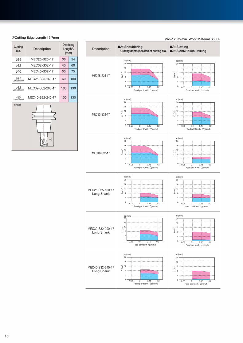
③Cutting Edge Length 15.7mm (Vc=120m/min Work Material:S50C)
Description■At Shouldering Cutting depth (ae)=half of cutting dia.
■At Slotting■At Slant/Helical Milling
MEC25-S25-17
0.050
4
8
12
16
20
0.1 0.15 0.2
ap(mm)
D.O
.C.
Feed per tooth fz(mm/t) 0.050
4
8
20
0.1 0.15 0.2
ap(mm)
D.O
.C.
Feed per tooth fz(mm/t)
MEC32-S32-17
0.050
4
8
12
16
20
0.1 0.15 0.2
ap(mm)
D.O
.C.
Feed per tooth fz(mm/t) 0.050
4
8
12
16
20
0.1 0.15 0.2
ap(mm)
D.O
.C.
Feed per tooth fz(mm/t)
MEC40-S32-17
0.050
4
8
12
16
20
0.1 0.15 0.2
ap(mm)
D.O
.C.
Feed per tooth fz(mm/t) 0.050
4
8
12
16
20
0.1 0.15 0.2
ap(mm)
D.O
.C.
Feed per tooth fz(mm/t)
MEC25-S25-160-17Long Shank
0.050
4
8
12
16
20
0.1 0.15 0.2
ap(mm)
D.O
.C.
Feed per tooth fz(mm/t) 0.050
4
8
12
16
20
0.1 0.15 0.2
ap(mm)
D.O
.C.
Feed per tooth fz(mm/t)
MEC32-S32-200-17Long Shank
0.050
4
8
12
16
20
0.1 0.15 0.2
ap(mm)
D.O
.C.
Feed per tooth fz(mm/t) 0.050
4
8
12
16
20
0.1 0.15 0.2
ap(mm)
D.O
.C.
Feed per tooth fz(mm/t)
MEC40-S32-240-17Long Shank
0.050
4
8
12
16
20
0.1 0.15 0.2
ap(mm)
D.O
.C.
Feed per tooth fz(mm/t) 0.050
4
8
12
16
20
0.1 0.15 0.2
ap(mm)
D.O
.C.
Feed per tooth fz(mm/t)
Cutting Dia.
DescriptionOverhang LengthA
(mm)
ø25 MEC25-S25-17 36 54
ø32 MEC32-S32-17 40 60
ø40 MEC40-S32-17 50 75
ø25Long Shank
MEC25-S25-160-17 60 100
ø32Long Shank
MEC32-S32-200-17 100 130
ø40Long Shank
MEC40-S32-240-17 100 130
Shape
15

●MEC type Cutting Performance of ULTRA HURRICANE FACEMILLCutting Edge Length 10mm
Cutting Dia.
DescriptionOverhang LengthA
(mm)
ø40 MEC040R-11-5T-M 115
ø50 MEC050R-11- T-M 100
ø63MEC063R-11- T
95MEC063R-11- T-M
ø80 MEC080R-11- T 95
ø100 MEC100R-11-9TN
108ø125 MEC125R-11-11T
ø160 MEC160R-11-14T
Shape
A
(Vc=120m/min Work Material:S50C)
Description■At Shouldering Cutting depth (ae)=half of cutting dia.
■At Slotting
MEC040R-11-5T-M
0.050
2
4
6
8
10
0.1 0.15 0.2
ap(mm)
D.O
.C.
Feed per tooth fz(mm/t) 0.050
2
4
6
8
10
0.1 0.15 0.2
ap(mm)
D.O
.C.
Feed per tooth fz(mm/t)
MEC050R-11- T-M~
MEC100R-11-9TN
0.050
2
4
6
8
10
0.1 0.15 0.2
ap(mm)
D.O
.C.
Feed per tooth fz(mm/t) 0.050
2
4
6
8
10
0.1 0.15 0.2
ap(mm)
D.O
.C.
Feed per tooth fz(mm/t)
MEC125R-11-11TMEC160R-11-14T
ap(mm)
0.050
2
4
6
8
10
0.1 0.15 0.2
D.O
.C.
Feed per tooth fz(mm/t)
ap(mm)
0.050
2
4
6
8
10
0.1 0.15 0.2
D.O
.C.
Feed per tooth fz(mm/t)
Cutting Dia.
DescriptionOverhang LengthA
(mm)
ø40 MEC040R-17-4T-M 115
ø50 MEC050R-17- T-M 100
ø63MEC063R-17- T
95MEC063R-17- T-M
ø80 MEC080R-17- T 95
ø100 MEC100R-17- TN
108ø125 MEC125R-17-9T
ø160 MEC160R-17-12T
Shape
A
(Vc=120m/min Work Material:S50C)
Description■At Shouldering Cutting depth (ae)=half of cutting dia.
■At Slotting
MEC040R-17-4T-M
0.050
4
8
12
16
20
0.1 0.15 0.2
ap(mm)
D.O
.C.
Feed per tooth fz(mm/t)
0
4
8
12
16
20
0.05 0.1 0.15 0.2
ap(mm)
D.O
.C.
Feed per tooth fz(mm/t)
MEC050R-17- T-M
0.05 0.1 0.15 0.20
4
8
12
16
20ap(mm)
D.O
.C.
Feed per tooth fz(mm/t)
0.05 0.1 0.15 0.20
4
8
12
16
20ap(mm)
D.O
.C.
Feed per tooth fz(mm/t)
MEC063R-17- T(-M)
~
MEC100R-17- TN
0.05 0.1 0.15 0.20
4
8
12
16
20ap(mm)
D.O
.C.
Feed per tooth fz(mm/t)
0.05 0.1 0.15 0.20
4
8
12
16
20
ap(mm)
D.O
.C.
Feed per tooth fz(mm/t)
MEC125R-17-9TMEC160R-17-12T
ap(mm)
0.050
4
8
12
16
20
0.1 0.15 0.2
D.O
.C.
Feed per tooth fz(mm/t)
ap(mm)
0.050
4
8
12
16
20
0.1 0.15 0.2
D.O
.C.
Feed per tooth fz(mm/t)
Cutting Edge Length 15.7mm
16
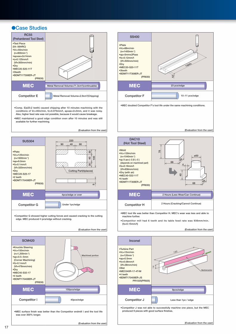
●Case StudiesRC55
(Prehardened Tool Steel)•Test Piece(54~56HRC)•Vc=50m/min (n=800min-1) •apxae=2x14mm •z=0.125mm/t (Vf=300mm/min) •Dry•MEC20-S20-11T •3teeth•BDMT11T308ER-JT
(PR830)
MEC
Competitor E
•Comp. E(ø25:2 teeth) caused chipping after 10 minutes machining with the conditions of Vc=40m/min, fz=0.075mm/t, apxae=2×3mm, and it was noisy.Also, higher feed rate was not possible, because it would cause breakage.
•MEC maintained a good edge condition even after 10 minutes and was still available for further machining.
(Evaluation from the user)
SS400
1800
10
•Plate•Vc=88m/min (n=1400min-1) •ap=5mmx2Pass•fz=0.12mm/t (Vf=500mm/min) •Dry•MEC20-S20-11T •3teeth•BDMT11T308ER-JT
(PR830)
MEC
Competitor F
•MEC doubled Competitor F's tool life under the same machining conditions.
(Evaluation from the user)
Metal Removal Volume=71.3cm3(continuable)
Metal Removal Volume=2.9cm3(Chipping)
23 pcs/edge
10~11 pcs/edge
SUS304 220
40
3030
40 100
9090
Cutting Part(4places)
9
•Plate•Vc=125m/min (n=1600min-1)•ap=9.0mm•fz=0.1mm/t (Vf=320mm/min)•Dry•MEC25-S25-17•2 teeth•BDMT170408ER-JT
(PR830)
MEC
Competitor G
•Competitor G showed higher cutting forces and caused cracking to the cutting edge. MEC produced 4 pcs/edge without cracking.
(Evaluation from the user)
DAC10 (Hot Tool Steel)
78
40
68
5858
4
68
ø50
•Mold•Vc=130m/min (n=1040min-1)•ap X ae=(~3 )X (~5 ) (depends on machined part)•fz=0.18mm/t (Vf=936mm/min)•Dry (with air)•MEC40-S32-11T•5 teeth•BDMT11T308ER-JT
(PR830)
MEC
Competitor H
•MEC tool life was better than Competitor H. MEC's wear was less and able to machine further.
•Competitor mill had 6 teeth and its table feed rate was 936mm/min. (fz=0.15mm/t)
(Evaluation from the user)
Under 1pc/edge 2 Hours (Cracking/Cannot Continue)
SCM420
Machined portion
•Knuckle Steering •Vc=150m/min (n=1,200min-1)•ap=0.5~5mm (Corner Machining)•fz=0.1mm/t (Vf=478mm/min)•Dry•MEC40-S32-17•4 teeth•BDMT170408ER-JT
(PR830)
MEC
Competitor I
•MEC surface finish was better than the Competitor endmill I and the tool life was over 300% longer.
(Evaluation from the user)
Inconel
Machined portion
•Turbine Part•Vc=15m/min (n=120min-1)•ap=0.5mm•fz=0.08mm/t (Vf=38mm/min)•Wet•MEC040R-17-4T-M•4 teeth•BDMT170408ER-JS
PR1025(PR925)
MEC
Competitor J
•Competitor J was not able to successfully machine one piece, but the MEC produced 9 pieces with good surface finishes.
(Evaluation from the user)
Less than 1pc / edge
4pcs/edge or over 2 Hours (Less Wear/Can Continue)
150pcs/edge
40pcs/edge
9pcs/edge
17
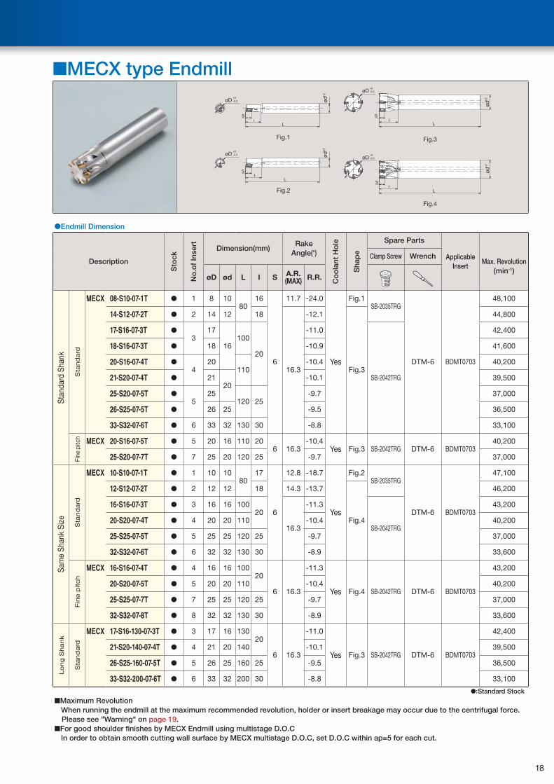
■MECX type Endmill
l
l
l
l
+0-0.2øD
+0-0.2øD
+0-0.2øD
+0-0.2øD
L
S
Fig.1
L
S
Fig.2
L
S
Fig.3
L
S
Fig.4
ødh7
ødh7
ødh7
ødh7
●Endmill Dimension
Description
Sto
ck
No
.of
Inse
rt Dimension(mm)Rake
Angle(°)
Co
ola
nt H
ole
Sha
pe
Spare Parts
Applicable Insert
Max. Revolution(min-1)
Clamp Screw Wrench
øD ød L l S A.R. (MAX) R.R.
Stan
dard
Sha
nk
Sta
nd
ard
MECX 08-S10-07-1T ● 1 8 1080
16
6
11.7 -24.0
Yes
Fig.1SB-2035TRG
DTM-6 BDMT0703
48,100
14-S12-07-2T ● 2 14 12 18
16.3
-12.1
Fig.3
44,800
17-S16-07-3T ●3
17
16100
20
-11.0
SB-2042TRG
42,400
18-S16-07-3T ● 18 -10.9 41,600
20-S16-07-4T ●4
20110
-10.4 40,200
21-S20-07-4T ● 2120
-10.1 39,500
25-S20-07-5T ●5
25120 25
-9.7 37,000
26-S25-07-5T ● 26 25 -9.5 36,500
33-S32-07-6T ● 6 33 32 130 30 -8.8 33,100
Fine
pitc
h MECX 20-S16-07-5T ● 5 20 16 110 206 16.3
-10.4 Yes Fig.3 SB-2042TRG DTM-6 BDMT0703
40,200
25-S20-07-7T ● 7 25 20 120 25 -9.7 37,000
Sam
e Sh
ank
Size
Sta
nd
ard
MECX 10-S10-07-1T ● 1 10 1080
17
6
12.8 -18.7
Yes
Fig.2SB-2035TRG
DTM-6 BDMT0703
47,100
12-S12-07-2T ● 2 12 12 18 14.3 -13.7
Fig.4
46,200
16-S16-07-3T ● 3 16 16 10020
16.3
-11.3
SB-2042TRG
43,200
20-S20-07-4T ● 4 20 20 110 -10.4 40,200
25-S25-07-5T ● 5 25 25 120 25 -9.7 37,000
32-S32-07-6T ● 6 32 32 130 30 -8.9 33,600
Fin
e p
itch
MECX 16-S16-07-4T ● 4 16 16 10020
6 16.3
-11.3
Yes Fig.4 SB-2042TRG DTM-6 BDMT0703
43,200
20-S20-07-5T ● 5 20 20 110 -10.4 40,200
25-S25-07-7T ● 7 25 25 120 25 -9.7 37,000
32-S32-07-8T ● 8 32 32 130 30 -8.9 33,600
Lo
ng
Shank
Sta
nd
ard
MECX 17-S16-130-07-3T ● 3 17 16 13020
6 16.3
-11.0
Yes Fig.3 SB-2042TRG DTM-6 BDMT0703
42,400
21-S20-140-07-4T ● 4 21 20 140 -10.1 39,500
26-S25-160-07-5T ● 5 26 25 160 25 -9.5 36,500
33-S32-200-07-6T ● 6 33 32 200 30 -8.8 33,100
●:Standard Stock
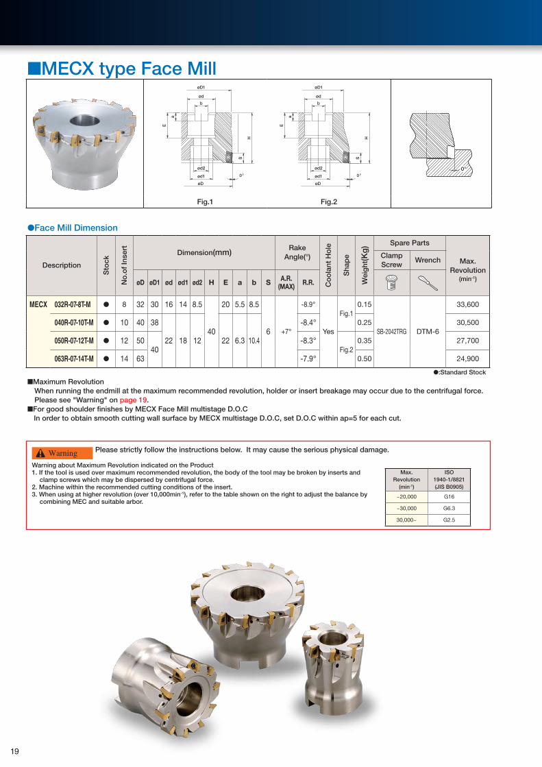
■Maximum Revolution When running the endmill at the maximum recommended revolution, holder or insert breakage may occur due to the centrifugal force.
Please see "Warning" on page 19.■For good shoulder finishes by MECX Endmill using multistage D.O.C In order to obtain smooth cutting wall surface by MECX multistage D.O.C, set D.O.C within ap=5 for each cut.
18
■MECX type Face Mill
øD
00
H
S
H
S
E
a
b
ød1
ød2
øD
ød1
ød2
E
a
b
ødød
øD1 øD1
0°
Fig.1 Fig.2
●Face Mill Dimension
Description
Sto
ck
No
.of
Inse
rt
Dimension(mm)Rake
Angle(°)
Co
ola
nt H
ole
Sha
pe
Wei
ght
(Kg
) Spare Parts
Max. Revolution
(min-1)
Clamp Screw
Wrench
øD øD1 ød ød1 ød2 H E a b S A.R.(MAX) R.R.
MECX 032R-07-8T-M ● 8 32 30 16 14 8.5
40
20 5.5 8.5
6 +7°
-8.9°
Yes
Fig.10.15
SB-2042TRG DTM-6
33,600
040R-07-10T-M ● 10 40 38
22 18 12 22 6.3 10.4
-8.4° 0.25 30,500
050R-07-12T-M ● 12 5040
-8.3°Fig.2
0.35 27,700
063R-07-14T-M ● 14 63 -7.9° 0.50 24,900
●:Standard Stock
■Maximum Revolution When running the endmill at the maximum recommended revolution, holder or insert breakage may occur due to the centrifugal force.
Please see "Warning" on page 19.■For good shoulder finishes by MECX Face Mill multistage D.O.C In order to obtain smooth cutting wall surface by MECX multistage D.O.C, set D.O.C within ap=5 for each cut.
Please strictly follow the instructions below. It may cause the serious physical damage.
Warning about Maximum Revolution indicated on the Product1. If the tool is used over maximum recommended revolution, the body of the tool may be broken by inserts and
clamp screws which may be dispersed by centrifugal force. 2. Machine within the recommended cutting conditions of the insert.3. When using at higher revolution (over 10,000min-1), refer to the table shown on the right to adjust the balance by
combining MEC and suitable arbor.
Max. Revolution
(min-1)
ISO 1940-1/8821(JIS B0905)
~20,000 G16
~30,000 G6.3
30,000~ G2.5
Warning
19
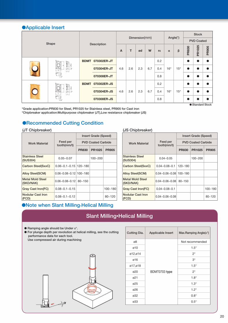
●Applicable Insert
Shape Description
Dimension(mm) Angle(°)Stock
PVD Coated
A T ød W rε α β
PR
830
PR
1025
PR
905
rε BDMT 070302ER-JT
4.6 2.6 2.3 6.7
0.2
16° 15°
● ● ●
070304ER-JT 0.4 ● ● ●
070308ER-JT 0.8 ● ● ●
rε BDMT 070302ER-JS
4.6 2.6 2.3 6.7
0.2
16° 15°
● ● ●
070304ER-JS 0.4 ● ● ●
070308ER-JS 0.8 ● ● ●
●:Standard Stock
*Grade application:PR830 for Steel, PR1025 for Stainless steel, PR905 for Cast iron*Chipbreaker application:Multipurpose chipbreaker (JT),Low resistance chipbreaker (JS)
●Recommended Cutting Condition(JT Chipbreaker) (JS Chipbreaker)
Work Material Feed per tooth(mm/t)
Insert Grade (Speed)
Work Material Feed pertooth(mm/t)
Insert Grade (Speed)
PVD Coated Carbide PVD Coated Carbide
PR830 PR1025 PR905 PR830 PR1025 PR905
Stainless Steel(SUS304)
0.05~0.07 100~200Stainless Steel(SUS304)
0.04~0.05 100~200
Carbon Steel(SxxC) 0.06~0.1~0.15 120~180 Carbon Steel(SxxC) 0.04~0.08~0.1 120~180
Alloy Steel(SCM) 0.06~0.08~0.12 100~180 Alloy Steel(SCM) 0.04~0.06~0.08 100~180
Metal Mold Steel(SKD/NAK)
0.06~0.08~0.12 80~150Metal Mold Steel(SKD/NAK)
0.04~0.06~0.08 80~150
Gray Cast Iron(FC) 0.08~0.1~0.15 100~180 Gray Cast Iron(FC) 0.04~0.08~0.1 100~180
Nodular Cast Iron(FCD)
0.08~0.1~0.12 80~120Nodular Cast Iron(FCD)
0.04~0.06~0.08 80~120
Slant Milling•Helical Milling
● Ramping angle should be Under α°.● For plunge depth per revolution at helical milling, see the cutting
performance data for each tool. Use compressed air during machining
●Note when Slant Milling.Helical Milling
Cutting Dia. Applicable Insert Max.Ramping Angle(α°)
ø8
BDMT0703 type
Not recommended
ø10 1.5°
ø12,ø14 2°
ø16 3°
ø17,ø18 1.5°
ø20 2°
ø21 1.8°
ø25 1.3°
ø26 1.2°
ø32 0.8°
ø33 0.5°
20

●Cutting Performance of MECX Type
Cutting Dia.
DescriptionOverhang
Length A(mm)
ø8 MECX08-S10-07-1T 16 -
ø10 MECX10-S10-07-1T 17 -
ø12 MECX12-S12-07-2T 18 30
ø16 MECX16-S16-07-3T 20 40
ø20 MECX20-S20-07-4T 20 40
ø25 MECX25-S25-07-5T 25 50
ø32 MECX32-S32-07-6T 30 50
Shape
A
* Machining by extending over hang of dia. 8mm and 10mm is not recommended.
*Cutting condition of JS Chipbreaker
①In case of MECX08~MECX12 Please decrease feed ratio about 25% according
to cutting capability list. ②In case of over MECX16 Lower feed ratio and D.O.C about 30% at the
same time according to cutting capability list.
(Vc=150m/min Work Material :S50C)
Description■At Shouldering Cutting depth (ae)=half of cutting dia.
■At Grooving■At Slant/Helical Milling
MECX08-S10-07-1T
0.050
1
3
2
4
5
6
0.1 0.15
ap(mm)
D.O
.C.
Feed per tooth fz(mm/t) 0.050
1
3
2
4
5
6
0.1 0.15
ap(mm)
D.O
.C.
Feed per tooth fz(mm/t)
MECX10-S10-07-1T
0.050
1
3
2
4
5
6
0.1 0.15
ap(mm)
D.O
.C.
Feed per tooth fz(mm/t)
ap(mm)
0.050
1
3
2
4
5
6
0.1 0.15
D.O
.C.
Feed per tooth fz(mm/t)
MECX12-S12-07-2T
0.050
1
3
2
4
5
6
0.1 0.15
ap(mm)
D.O
.C.
Feed per tooth fz(mm/t) 0.050
1
3
2
4
5
6
0.1 0.15
ap(mm)
D.O
.C.
Feed per tooth fz(mm/t)
MECX16-S16-07-3T
0.050
1
3
2
4
5
6
0.1 0.15
ap(mm)
D.O
.C.
Feed per tooth fz(mm/t) 0.050
1
3
2
4
5
6
0.1 0.15
ap(mm)
D.O
.C.
Feed per tooth fz(mm/t)
MECX20-S20-07-4T
0.050
1
3
2
4
5
6
0.1 0.15
D.O
.C.
ap(mm)
Feed per tooth fz(mm/t) 0.050
1
3
2
4
5
6
0.1 0.15
ap(mm)
D.O
.C.
Feed per tooth fz(mm/t)
MECX25-S25-07-5T
0.050
1
3
2
4
5
6
0.1 0.15
ap(mm)
D.O
.C.
Feed per tooth fz(mm/t) 0.050
1
3
2
4
5
6
0.1 0.15
ap(mm)
D.O
.C.
Feed per tooth fz(mm/t)
MECX32-S32-07-6T
0.050
1
3
2
4
5
6
0.1 0.15
ap(mm)
D.O
.C.
Feed per tooth fz(mm/t) 0.050
1
3
2
4
5
6
0.1 0.15
ap(mm)
D.O
.C.
Feed per tooth fz(mm/t)
* Above cutting capability list illustrates application range of standard edge number of JT Chipbreaker (PR830)Please use multiple edge type under 70% of D.O.C.
21
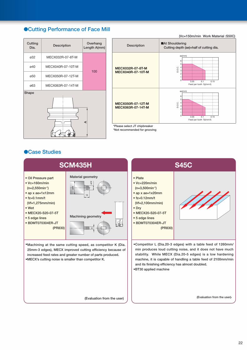
●Cutting Performance of Face Mill
Cutting Dia.
DescriptionOverhang
Length A(mm)
ø32 MECX032R-07-8T-M
100ø40 MECX040R-07-10T-M
ø50 MECX050R-07-12T-M
ø63 MECX063R-07-14T-M
Shape
A
(Vc=150m/min Work Material :S50C)
Description■At Shouldering Cutting depth (ae)=half of cutting dia.
MECX032R-07-8T-MMECX040R-07-10T-M
ap(mm)
0.050
1
3
2
4
5
6
0.1 0.15
D.O
.C.
Feed per tooth fz(mm/t)
MECX050R-07-12T-MMECX063R-07-14T-M
0.050
1
3
2
4
5
6
0.1 0.15
ap(mm)
D.O
.C.
Feed per tooth fz(mm/t)
*Please select JT chipbreaker*Not recommended for grooving
●Case Studies
SCM435H
• Oil Pressure part
• Vc=160m/min
(n=2,550min-1)
• ap x ae=1x12mm
• fz=0.1mm/t
(Vf=1,275mm/min)
• Wet
• MECX20-S20-07-5T
• 5 edge lines
• BDMT070304ER-JT
(PR830)
•Machining at the same cutting speed, as competitor K (Dia.
25mm-3 edges), MECX improved cutting efficiency because of
increased feed rates and greater number of parts produced. •MECX’s cutting noise is smaller than competitor K.
(Evaluation from the user)
8
14
ø12
ø35
Material geometry
Machining geometry
S45C
• Plate
• Vc=220m/min
(n=3,500min-1)
• ap x ae=1x20mm
• fz=0.12mm/t
(Vf=2,100mm/min)
• Dry
• MECX20-S20-07-5T
• 5 edge lines
• BDMT070304ER-JT
(PR830)
•Competitor L (Dia.20-3 edges) with a table feed of 1260mm/
min produces loud cutting noise, and it does not have much
stability. While MECX (Dia.20-5 edges) is a low hardening
machine, it is capable of handling a table feed of 2100mm/min
and its finishing efficiency has almost doubled.
•BT30 applied machine
(Evaluation from the user)r
22
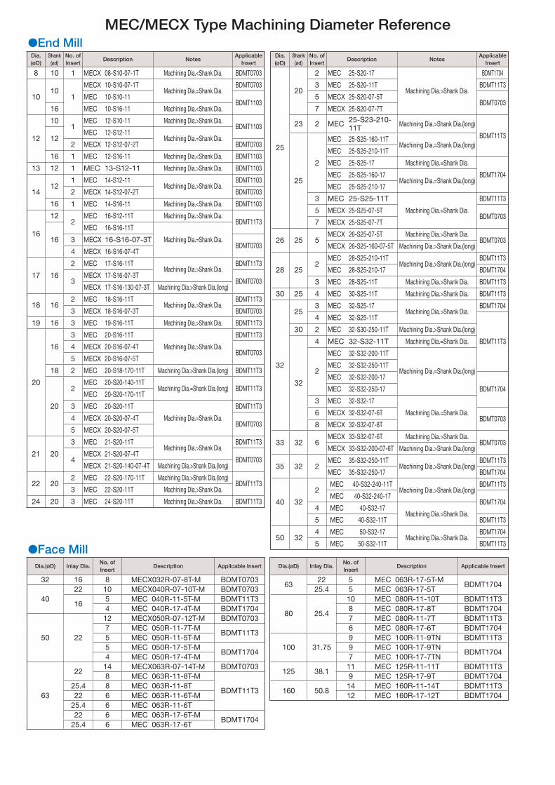
MEC/MECX Type Machining Diameter Reference●End MillDia.(øD)
Shank(ød)
No. of Insert
Description NotesApplicable
Insert
8 10 1 MECX 08-S10-07-1T Machining Dia.<Shank Dia. BDMT0703
1010
1
MECX 10-S10-07-1TMachining Dia.=Shank Dia.
BDMT0703
MEC 10-S10-11BDMT1103
16 MEC 10-S16-11 Machining Dia.<Shank Dia.
12
101
MEC 12-S10-11 Machining Dia.>Shank Dia.BDMT1103
12MEC 12-S12-11
Machining Dia.=Shank Dia.2 MECX 12-S12-07-2T BDMT0703
16 1 MEC 12-S16-11 Machining Dia.<Shank Dia. BDMT1103
13 12 1 MEC 13-S12-11 Machining Dia.>Shank Dia. BDMT1103
1412
1 MEC 14-S12-11Machining Dia.>Shank Dia.
BDMT1103
2 MECX 14-S12-07-2T BDMT0703
16 1 MEC 14-S16-11 Machining Dia.<Shank Dia. BDMT1103
16
122
MEC 16-S12-11T Machining Dia.>Shank Dia.BDMT11T3
16
MEC 16-S16-11T
Machining Dia.=Shank Dia.3 MECX 16-S16-07-3TBDMT0703
4 MECX 16-S16-07-4T
17 16
2 MEC 17-S16-11TMachining Dia.>Shank Dia.
BDMT11T3
3MECX 17-S16-07-3T
BDMT0703MECX 17-S16-130-07-3T Machining Dia.>Shank Dia.(long)
18 162 MEC 18-S16-11T
Machining Dia.>Shank Dia.BDMT11T3
3 MECX 18-S16-07-3T BDMT0703
19 16 3 MEC 19-S16-11T Machining Dia.>Shank Dia. BDMT11T3
20
16
3 MEC 20-S16-11T
Machining Dia.>Shank Dia.
BDMT11T3
4 MECX 20-S16-07-4TBDMT0703
5 MECX 20-S16-07-5T
18 2 MEC 20-S18-170-11T Machining Dia.>Shank Dia.(long) BDMT11T3
20
2MEC 20-S20-140-11T
Machining Dia.=Shank Dia.(long) BDMT11T3MEC 20-S20-170-11T
3 MEC 20-S20-11T
Machining Dia.=Shank Dia.
BDMT11T3
4 MECX 20-S20-07-4TBDMT0703
5 MECX 20-S20-07-5T
21 20
3 MEC 21-S20-11TMachining Dia.>Shank Dia.
BDMT11T3
4MECX 21-S20-07-4T
BDMT0703MECX 21-S20-140-07-4T Machining Dia.>Shank Dia.(long)
22 202 MEC 22-S20-170-11T Machining Dia.>Shank Dia.(long)
BDMT11T33 MEC 22-S20-11T Machining Dia.>Shank Dia.
24 20 3 MEC 24-S20-11T Machining Dia.>Shank Dia. BDMT11T3
Dia.(øD)
Shank(ød)
No. of Insert
Description NotesApplicable
Insert
25
20
2 MEC 25-S20-17
Machining Dia.>Shank Dia.
BDMT1704
3 MEC 25-S20-11T BDMT11T3
5 MECX 25-S20-07-5TBDMT0703
7 MECX 25-S20-07-7T
23 2 MEC 25-S23-210-11T Machining Dia.>Shank Dia.(long)
BDMT11T3
25
2
MEC 25-S25-160-11TMachining Dia.=Shank Dia.(long)
MEC 25-S25-210-11T
MEC 25-S25-17 Machining Dia.=Shank Dia.
BDMT1704MEC 25-S25-160-17Machining Dia.=Shank Dia.(long)
MEC 25-S25-210-17
3 MEC 25-S25-11T
Machining Dia.=Shank Dia.
BDMT11T3
5 MECX 25-S25-07-5TBDMT0703
7 MECX 25-S25-07-7T
26 25 5MECX 26-S25-07-5T Machining Dia.>Shank Dia.
BDMT0703MECX 26-S25-160-07-5T Machining Dia.>Shank Dia.(long)
28 252
MEC 28-S25-210-11TMachining Dia.>Shank Dia.(long)
BDMT11T3
MEC 28-S25-210-17 BDMT1704
3 MEC 28-S25-11T Machining Dia.>Shank Dia. BDMT11T3
30 25 4 MEC 30-S25-11T Machining Dia.>Shank Dia. BDMT11T3
32
253 MEC 32-S25-17
Machining Dia.>Shank Dia.BDMT1704
4 MEC 32-S25-11T
BDMT11T3
30 2 MEC 32-S30-250-11T Machining Dia.>Shank Dia.(long)
32
4 MEC 32-S32-11T Machining Dia.=Shank Dia.
2
MEC 32-S32-200-11T
Machining Dia.=Shank Dia.(long)MEC 32-S32-250-11T
MEC 32-S32-200-17
BDMT1704MEC 32-S32-250-17
3 MEC 32-S32-17
Machining Dia.=Shank Dia.6 MECX 32-S32-07-6TBDMT0703
8 MECX 32-S32-07-8T
33 32 6MECX 33-S32-07-6T Machining Dia.>Shank Dia.
BDMT0703MECX 33-S32-200-07-6T Machining Dia.>Shank Dia.(long)
35 32 2MEC 35-S32-250-11T
Machining Dia.>Shank Dia.(long)BDMT11T3
MEC 35-S32-250-17 BDMT1704
40 32
2MEC 40-S32-240-11T
Machining Dia.>Shank Dia.(long)BDMT11T3
MEC 40-S32-240-17BDMT1704
4 MEC 40-S32-17Machining Dia.>Shank Dia.
5 MEC 40-S32-11T BDMT11T3
50 324 MEC 50-S32-17
Machining Dia.>Shank Dia.BDMT1704
5 MEC 50-S32-11T BDMT11T3●Face Mill
Dia.(øD) Inlay Dia.No. of Insert
Description Applicable Insert Dia.(øD) Inlay Dia.No. of Insert
Description Applicable Insert
32 16 8 MECX032R-07-8T-M BDMT070363
22 5 MEC 063R-17-5T-MBDMT1704
4022 10 MECX040R-07-10T-M BDMT0703 25.4 5 MEC 063R-17-5T
165 MEC 040R-11-5T-M BDMT11T3
80 25.4
10 MEC 080R-11-10T BDMT11T34 MEC 040R-17-4T-M BDMT1704 8 MEC 080R-17-8T BDMT1704
50 22
12 MECX050R-07-12T-M BDMT0703 7 MEC 080R-11-7T BDMT11T37 MEC 050R-11-7T-M
BDMT11T36 MEC 080R-17-6T BDMT1704
5 MEC 050R-11-5T-M100 31.75
9 MEC 100R-11-9TN BDMT11T35 MEC 050R-17-5T-M
BDMT17049 MEC 100R-17-9TN
BDMT17044 MEC 050R-17-4T-M 7 MEC 100R-17-7TN
63
2214 MECX063R-07-14T-M BDMT0703
125 38.111 MEC 125R-11-11T BDMT11T3
8 MEC 063R-11-8T-M
BDMT11T3
9 MEC 125R-17-9T BDMT170425.4 8 MEC 063R-11-8T
160 50.814 MEC 160R-11-14T BDMT11T3
22 6 MEC 063R-11-6T-M 12 MEC 160R-17-12T BDMT170425.4 6 MEC 063R-11-6T22 6 MEC 063R-17-6T-M
BDMT170425.4 6 MEC 063R-17-6T


