13 Hedin Equations, GW, GW+DMFT,
and All That
K. Held, C. Taranto, G. Rohringer, and A. Toschi
Institute for Solid State Physics
Vienna University of Technology, 1040 Vienna, Austria
Contents
1 Introduction 2
2 Hedin equations 4
3 GW approximation 10
3.1 From Hedin equations to GW . . . . . . . . . . . . . . . . . . . . . . . . . . . 10
3.2 GW band gaps and quasiparticles . . . . . . . . . . . . . . . . . . . . . . . . . 11
4 GW+DMFT 12
5 All of that: ab intito DΓA 16
A Additional steps: equation of motion 18
E. Pavarini, E. Koch, Dieter Vollhardt, and Alexander LichtensteinThe LDA+DMFT approach to strongly correlated materialsModeling and Simulation Vol. 1Forschungszentrum Julich, 2011, ISBN 978-3-89336-734-4http://www.cond-mat.de/events/correl11
13.2 K. Held, C. Taranto, G. Rohringer, and A. Toschi
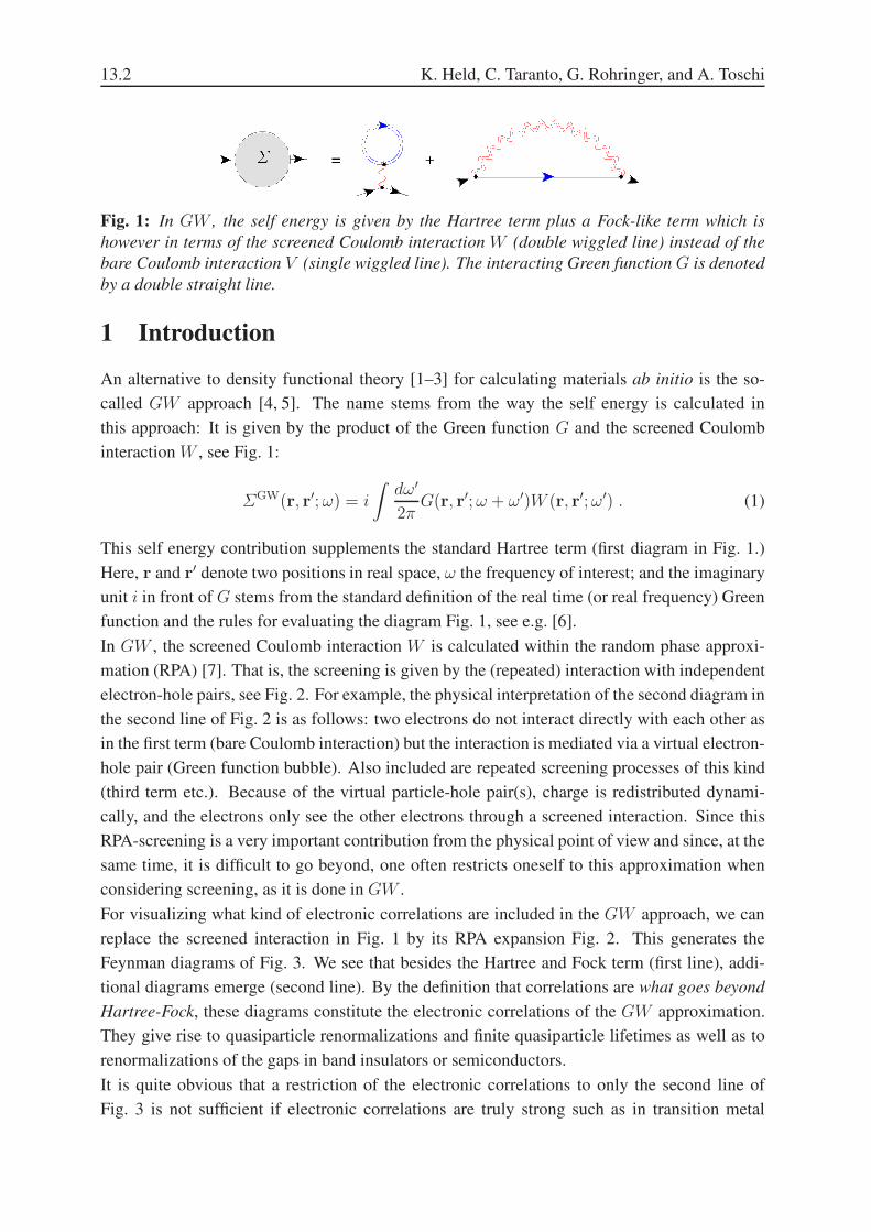
Fig. 1: In GW , the self energy is given by the Hartree term plus a Fock-like term which is
however in terms of the screened Coulomb interaction W (double wiggled line) instead of the
bare Coulomb interaction V (single wiggled line). The interacting Green function G is denoted
by a double straight line.
1 Introduction
An alternative to density functional theory [1–3] for calculating materials ab initio is the so-
called GW approach [4, 5]. The name stems from the way the self energy is calculated in
this approach: It is given by the product of the Green function G and the screened Coulomb
interaction W , see Fig. 1:
ΣGW(r, r′;ω) = i
∫dω′
2πG(r, r′;ω + ω′)W (r, r′;ω′) . (1)
This self energy contribution supplements the standard Hartree term (first diagram in Fig. 1.)
Here, r and r′ denote two positions in real space, ω the frequency of interest; and the imaginary
unit i in front of G stems from the standard definition of the real time (or real frequency) Green
function and the rules for evaluating the diagram Fig. 1, see e.g. [6].
In GW , the screened Coulomb interaction W is calculated within the random phase approxi-
mation (RPA) [7]. That is, the screening is given by the (repeated) interaction with independent
electron-hole pairs, see Fig. 2. For example, the physical interpretation of the second diagram in
the second line of Fig. 2 is as follows: two electrons do not interact directly with each other as
in the first term (bare Coulomb interaction) but the interaction is mediated via a virtual electron-
hole pair (Green function bubble). Also included are repeated screening processes of this kind
(third term etc.). Because of the virtual particle-hole pair(s), charge is redistributed dynami-
cally, and the electrons only see the other electrons through a screened interaction. Since this
RPA-screening is a very important contribution from the physical point of view and since, at the
same time, it is difficult to go beyond, one often restricts oneself to this approximation when
considering screening, as it is done in GW .
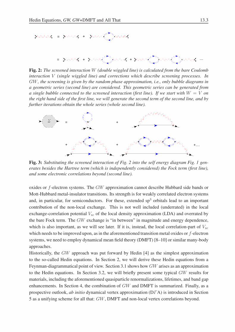
For visualizing what kind of electronic correlations are included in the GW approach, we can
replace the screened interaction in Fig. 1 by its RPA expansion Fig. 2. This generates the
Feynman diagrams of Fig. 3. We see that besides the Hartree and Fock term (first line), addi-
tional diagrams emerge (second line). By the definition that correlations are what goes beyond
Hartree-Fock, these diagrams constitute the electronic correlations of the GW approximation.
They give rise to quasiparticle renormalizations and finite quasiparticle lifetimes as well as to
renormalizations of the gaps in band insulators or semiconductors.
It is quite obvious that a restriction of the electronic correlations to only the second line of
Fig. 3 is not sufficient if electronic correlations are truly strong such as in transition metal
Hedin Equations, GW, GW+DMFT and All That 13.3
= +
= + ...+
Fig. 2: The screened interaction W (double wiggled line) is calculated from the bare Coulomb
interaction V (single wiggled line) and corrections which describe screening processes. In
GW , the screening is given by the random phase approximation, i.e., only bubble diagrams in
a geometric series (second line) are considered. This geometric series can be generated from
a single bubble connected to the screened interaction (first line). If we start with W = V on
the right hand side of the first line, we will generate the second term of the second line, and by
further iterations obtain the whole series (whole second line).
+
++
=
+...
Fig. 3: Substituting the screened interaction of Fig. 2 into the self energy diagram Fig. 1 gen-
erates besides the Hartree term (which is independently considered) the Fock term (first line),
and some electronic correlations beyond (second line).
oxides or f -electron systems. The GW approximation cannot describe Hubbard side bands or
Mott-Hubbard metal-insulator transitions. Its strength is for weakly correlated electron systems
and, in particular, for semiconductors. For these, extended sp3 orbitals lead to an important
contribution of the non-local exchange. This is not well included (underrated) in the local
exchange-correlation potential Vxc of the local density approximation (LDA) and overrated by
the bare Fock term. The GW exchange is “in between” in magnitude and energy dependence,
which is also important, as we will see later. If it is, instead, the local correlation-part of Vxc
which needs to be improved upon, as in the aforementioned transition metal oxides or f -electron
systems, we need to employ dynamical mean field theory (DMFT) [8–10] or similar many-body
approaches.
Historically, the GW approach was put forward by Hedin [4] as the simplest approximation
to the so-called Hedin equations. In Section 2, we will derive these Hedin equations from a
Feynman-diagrammatical point of view. Section 3.1 shows how GW arises as an approximation
to the Hedin equations. In Section 3.2, we will briefly present some typical GW results for
materials, including the aforementioned quasiparticle renormalizations, lifetimes, and band gap
enhancements. In Section 4, the combination of GW and DMFT is summarized. Finally, as a
prospective outlook, ab initio dynamical vertex approximation (DΓA) is introduced in Section
5 as a unifying scheme for all that: GW , DMFT and non-local vertex correlations beyond.
13.4 K. Held, C. Taranto, G. Rohringer, and A. Toschi
2 Hedin equations
In his seminal paper [4], Hedin noted, when deriving the equations bearing his name: ”The
results [i.e., the Hedin equations] are well known to the Green function people”. And indeed,
what is known as the Hedin equations in the bandstructure community are simply the Heisen-
berg equation of motion for the self energy (also known as Schwinger-Dyson equation) and the
standard relations between irreducible and reducible vertex, self energy and Green function, po-
larization operator and screened interaction. While Hedin gave an elementary derivation with
only second quantization as a prerequisite, we will discuss these from a Feynman diagram-
matic point of view as the reader/student shall by now be familiar with this technique from the
previous chapters/lectures of the Summer School. Our point of view gives a complementary
perspective and sheds some light to the relation to standard many body theory. For Hedin’s
elementary derivation based on functional derivatives see [4] and [5].
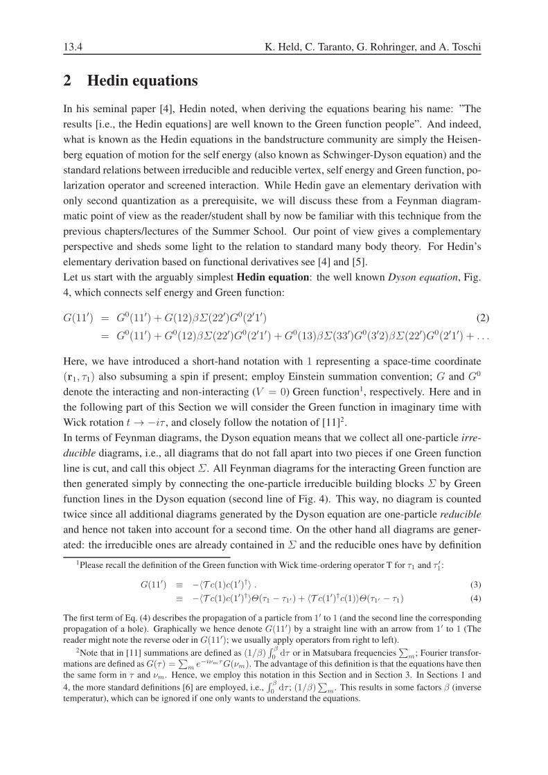
Let us start with the arguably simplest Hedin equation: the well known Dyson equation, Fig.
4, which connects self energy and Green function:
G(11′) = G0(11′) +G(12)βΣ(22′)G0(2′1′) (2)
= G0(11′) +G0(12)βΣ(22′)G0(2′1′) +G0(13)βΣ(33′)G0(3′2)βΣ(22′)G0(2′1′) + . . .
Here, we have introduced a short-hand notation with 1 representing a space-time coordinate
(r1, τ1) also subsuming a spin if present; employ Einstein summation convention; G and G0
denote the interacting and non-interacting (V = 0) Green function1, respectively. Here and in
the following part of this Section we will consider the Green function in imaginary time with
Wick rotation t → −iτ , and closely follow the notation of [11]2.
In terms of Feynman diagrams, the Dyson equation means that we collect all one-particle irre-
ducible diagrams, i.e., all diagrams that do not fall apart into two pieces if one Green function
line is cut, and call this object Σ. All Feynman diagrams for the interacting Green function are
then generated simply by connecting the one-particle irreducible building blocks Σ by Green
function lines in the Dyson equation (second line of Fig. 4). This way, no diagram is counted
twice since all additional diagrams generated by the Dyson equation are one-particle reducible
and hence not taken into account for a second time. On the other hand all diagrams are gener-
ated: the irreducible ones are already contained in Σ and the reducible ones have by definition
1Please recall the definition of the Green function with Wick time-ordering operator T for τ1 and τ ′1:
G(11′) ≡ −〈T c(1)c(1′)†〉 . (3)
≡ −〈T c(1)c(1′)†〉Θ(τ1 − τ1′) + 〈T c(1′)†c(1)〉Θ(τ1′ − τ1) (4)
The first term of Eq. (4) describes the propagation of a particle from 1′ to 1 (and the second line the corresponding
propagation of a hole). Graphically we hence denote G(11′) by a straight line with an arrow from 1′ to 1 (The
reader might note the reverse oder in G(11′); we usually apply operators from right to left).2Note that in [11] summations are defined as (1/β)
∫ β
0dτ or in Matsubara frequencies
∑
m; Fourier transfor-
mations are defined asG(τ) =∑
m e−iνmτG(νm). The advantage of this definition is that the equations have then
the same form in τ and νm. Hence, we employ this notation in this Section and in Section 3. In Sections 1 and
4, the more standard definitions [6] are employed, i.e.,∫ β
0dτ ; (1/β)
∑
m. This results in some factors β (inverse
temperatur), which can be ignored if one only wants to understand the equations.

Hedin Equations, GW, GW+DMFT and All That 13.5
+=
+ += ...
Fig. 4: One of the five Hedin equations is the well-known Dyson equation, connecting the
interacting Green function G (double line), non-interacting Green function G0 (single line) and
self energy Σ.
the form of the second line of Fig. 4.
Let us note that the Dyson equation (2) can be resolved for
G(11′) =
([(G0
)−1− βΣ
]−1)
(11′)
(5)
with a matrix inversion in the spatial and temporal coordinates. It is invariant under a basis
transformation from r1 to, say, an orbital basis or from time to frequency (note in a momentum-
frequency basis, the G and Σ matrices are diagonal).
A second equation of the five Hedin equations actually has the same form as the Dyson equation
but with the Green function and interaction changing their role. It relates the screened Coulomb
interaction W to the polarization operator P , see Fig. 5, which is a generalization of Fig. 2 to
arbitrary polarizations. As W we simply define (sum) all Feynman diagrams which connect to
the left and right side by interactions V . Physically, this means that we consider, besides the
bare interaction, also all more complicated processes involving additional electrons (screening).
Similar as for the Dyson equation (2), we collect all Feynman diagrams which do not fall apart
into a left and a right side by cutting one interaction line V , and call this object P . From P , we
can generate all diagrams of W connecting left and right side by a geometric series (second and
third line of Fig. 5) with a repeated application of P and V (second line of Fig. 5). As for the
Dyson equation, we generate all Feynman diagrams (in this case for W ) and count none twice
this way.
Mathematically, Fig. 5 translates into a second Hedin equation
W (11′; 22′) = V (11′; 22′) +W (11′; 33′)P (3′3; 4′4)V (44′; 22′) . (6)
Note, that in a general basis the two particle objects have four indices: an incoming particle 2’
and hole 2, and an outgoing particle 1’ and hole 1, with possible four different orbital indices.
In real space two of the indices are identical r1 = r1′ and r2 = r2′ .3
Next, we turn to the polarization operator P which can be related to a vertex Γ ∗. This is the
standard relation between two particle Green functions (or response functions) and the vertex
3 This is obvious for the bare Coulomb interaction V (r1, r′1; r2, r
′2) = V (r1, r2)δ(r1 − r
′1)δ(r2 − r
′2) with
V (r1, r2) = e2
4πǫ0
1
|r1−r2|. As one can see in Fig. 5 this property is transfered to W for which hence only a
polarization with two r’s needs to be calculated in real space.

13.6 K. Held, C. Taranto, G. Rohringer, and A. Toschi
=
= +
+
P
+ ...P P
+ P
Fig. 5: A second of the five Hedin equations is an ananlogon of the Dyson equation, Fig.
4 but for the Coulomb interaction. It relates the screened Coulomb interaction W (double
wiggled line) with the bare Coulomb interaction V and the polarization operator P . As the
Dyson equation can be considered as the defining equation for Σ, this second Hedin equation
effectively defines what P is.
+
=
=
( +
P
)Fig. 6: A third Hedin equation relates the polarization operator P to two separated Green
functions (“bubble” term) plus vertex (Γ ∗) corrections. This is the standard relation between
two particle Green functions and fully reducible vertex Γ . However since the polarization
operator cannot include interaction-reducible diagrams Γ has to be replaced by Γ ∗ (see text).
Second line: In terms of real space or momentum (but not in an orbital representation) two
indices can be contracted to a single one (cf. footnote 3).
and represents a third Hedin equation. That is P is given by the simple connection of left and
right side by two (separated) Green functions plus vertex corrections, see Fig. 6:
P (11′; 22′) = βG(12′)G(21′) + βG(13)G(3′1′)Γ ∗(33′; 44′)βG(4′2′)G(24) . (7)
Note, in real space 2 = 2′ and 1 = 1′ (cf. footnote 3) so that working with a two index
object, see second line of Fig. 6, is possible (and was done by Hedin), the inverse temperature β
(kB ≡ 1) arises from the rules for Feynman diagrams in imaginary times/frequencies, see [11].
Let us keep in mind, that in P or Γ ∗ not all Feynman diagrams are included: those diagrams,
that can be separated into left and right by cutting a single interaction line have to be explicitly
excluded, see Fig. 7. This is the reason why we put the symbol ∗ to the vertex Γ ∗; indicating
that some diagrams of the full vertex Γ are missing.
Having introduced the two-particle vertex Γ ∗, the fourth Hedin equation is obtained by relat-
ing this vertex to another object, the particle-hole irreducible vertex Γ ∗ph. This relation is the

Hedin Equations, GW, GW+DMFT and All That 13.7
Fig. 7: Left: A Feynman diagram that is not part of Γ ∗ (or P ) since cutting a single interaction
line separates the diagram into left and right part. Right: This Feynman diagram is included in
Γ ∗ (or P ).
= ph* + ph
*
Fig. 8: A fourth Hedin equation is the Bethe-Salpeter equation between the irreducible Γ ∗ph and
particle-hole reducible vertex Γ ∗. The particle-hole irreducible vertex Γ ∗ph collects the Feynman
diagrams which cannot be separated into left and right part by cutting two Green function lines.
All diagrams are then generated by the Bethe-Salpeter equation.
standard Bethe-Salpeter equation. As in the Dyson equation, we define the vertex Γ ∗ as the
irreducible vertex Γ ∗ph plus a geometric series of repetitions of Γ ∗
ph connected by two Green
functions, see Fig. 8:
Γ ∗(11′; 22′) = Γ ∗ph(11
′; 22′) + Γ ∗(11′; 33′)βG(3′4)G(4′3)Γ ∗ph(44
′; 22′) (8)
Here, the particle-hole irreducible vertex collects all Feynman diagrams which cannot be sepa-
rated by cutting two Green function lines into a left and right (incoming and outgoing) part. The
Bethe-Salpeter equation then generates all vertex diagrams by connecting the irreducible build-
ing blocks with two Green function lines, in analogy to the Dyson equation for the one-particle
irreducible vertex Σ.
Since in the polarization operator P (and the corresponding reducible vertex vertex Γ ∗) dia-
grams which connect left and right by only one bare Coulomb interaction line V are however
excluded, we have to explicitly take out this bare Coulomb interaction V from the vertex Γ ∗,
i.e., we have the standard particle-hole vertex Γph (i.e., all particle-hole irreducible diagrams)
minus the bare Coulomb interaction V diagram, see Fig. 9:
Γ ∗ph(11
′; 22′) = Γph(11′; 22′)− V (11′; 22′) (9)
The bare V and any combinations of Γ ∗ph and V are then generated in the screening equation
(6), Fig. 5.

13.8 K. Held, C. Taranto, G. Rohringer, and A. Toschi
= ph −ph*
Fig. 9: We have to exclude the bare Coulomb interaction V from the particle-hole vertex Γph
since such contributions are already considered in Fig. 5.
Fig. 10: By hands of selected Feynman diagrams we illustrate that differentiation of Σ w.r.t. Gyields the particle-hole irreducible vertex.
In this fourth equation, Hedin directly expresses Γ ∗ph as the derivative of the self-energy w.r.t.
the Green function [5] (respectively V [4]). This is a standard quantum field theoretical relation
Γph(11′; 22′) =
δΣ(11′)
δG(2′2), (10)
which in terms of Feynman diagrams follows from the observation that differentiation w.r.t. G
means removing one Green function line, see Fig. 10 and Ref. [11]. If we, as Hedin, consider
the self energy without Hartree term ΣHartree(11′) = V (11′; 22′)G(2′2) we obtain the vertex
Γ ∗ph instead of Γph:
Γ ∗ph(11
′; 22′) =δ[Σ(11′)−ΣHartree(11
′)]
δG(2′2)(11)
Note, the derivative of the Hartree term w.r.t. G(2′2) yields V (11′; 22′), i.e., precisely the term
not included in Γ ∗ph, see first diagram of Fig. 10.
The fifth Hedin equation is the Heisenberg equation of motion for the self energy, which
follows from the derivative of the Green function (3) w.r.t. τ1, i.e., the time-part of the coordinate
Hedin Equations, GW, GW+DMFT and All That 13.9
1. Let us start with the Heisenberg equation for the Heisenberg operator c(1) (~ ≡ 1):
−∂c(r1, τ1)
∂τ1= [c(r1, τ1), H ] (12)
and a general Hamiltonian of the form
H = H0(11′)c(1)†c(1′) +
1
2V (11′; 22′)c(1)†c(1′)c(2)†c(2′). (13)
From Eq. (12), we obtain the Heisenberg equation of motion for the Green function:4
−∂G(11′)
∂τ1= δ(1− 1′) +H0(12
′)G(2′1′)− V (13′; 22′)〈T c(3′)c(2)†c(2′)c(1′)†〉 . (14)
The last term on the right hand side of Eq. (14) is by definition the self energy times the Green
function. Hence this combination equals the interaction V times a two-particle Green function.
The two particle Green function in turn is, in analogy to Fig. 6, given by the bubble term (two
Green function lines; there are actually two terms of this: crossed and non-crossed) and vertex
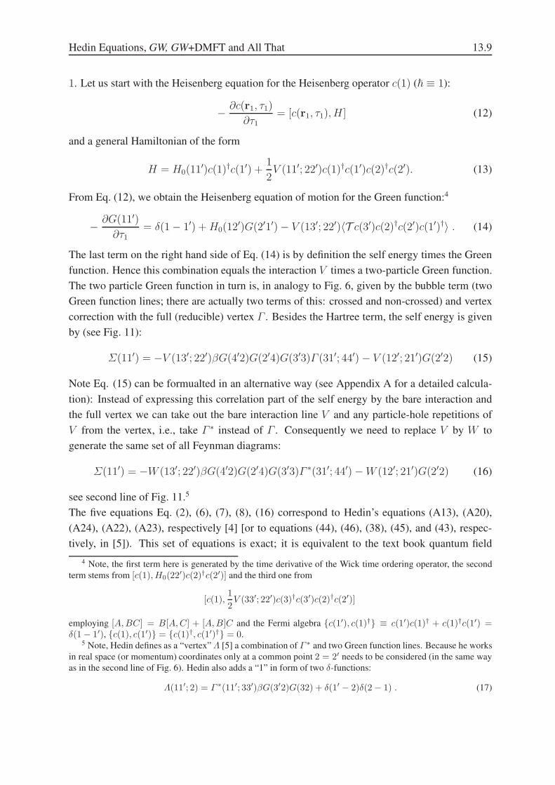
correction with the full (reducible) vertex Γ . Besides the Hartree term, the self energy is given
by (see Fig. 11):
Σ(11′) = −V (13′; 22′)βG(4′2)G(2′4)G(3′3)Γ (31′; 44′)− V (12′; 21′)G(2′2) (15)
Note Eq. (15) can be formualted in an alternative way (see Appendix A for a detailed calcula-
tion): Instead of expressing this correlation part of the self energy by the bare interaction and
the full vertex we can take out the bare interaction line V and any particle-hole repetitions of
V from the vertex, i.e., take Γ ∗ instead of Γ . Consequently we need to replace V by W to
generate the same set of all Feynman diagrams:
Σ(11′) = −W (13′; 22′)βG(4′2)G(2′4)G(3′3)Γ ∗(31′; 44′)−W (12′; 21′)G(2′2) (16)
see second line of Fig. 11.5
The five equations Eq. (2), (6), (7), (8), (16) correspond to Hedin’s equations (A13), (A20),
(A24), (A22), (A23), respectively [4] [or to equations (44), (46), (38), (45), and (43), respec-
tively, in [5]). This set of equations is exact; it is equivalent to the text book quantum field
4 Note, the first term here is generated by the time derivative of the Wick time ordering operator, the second
term stems from [c(1), H0(22′)c(2)†c(2′)] and the third one from
[c(1),1
2V (33′; 22′)c(3)†c(3′)c(2)†c(2′)]
employing [A,BC] = B[A,C] + [A,B]C and the Fermi algebra {c(1′), c(1)†} ≡ c(1′)c(1)† + c(1)†c(1′) =δ(1− 1′), {c(1), c(1′)} = {c(1)†, c(1′)†} = 0.
5 Note, Hedin defines as a “vertex”Λ [5] a combination of Γ ∗ and two Green function lines. Because he works
in real space (or momentum) coordinates only at a common point 2 = 2′ needs to be considered (in the same way
as in the second line of Fig. 6). Hedin also adds a “1” in form of two δ-functions:
Λ(11′; 2) = Γ ∗(11′; 33′)βG(3′2)G(32) + δ(1′ − 2)δ(2− 1) . (17)
13.10 K. Held, C. Taranto, G. Rohringer, and A. Toschi
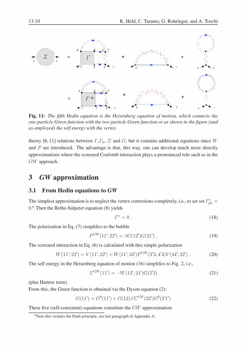
Fig. 11: The fifth Hedin equation is the Heisenberg equation of motion, which connects the
one-particle Green function with the two particle Green function or as shown in the figure (and
as employed) the self energy with the vertex.
theory [6, 11] relations between Γ ,Γir, Σ and G; but it contains additional equations since W
and P are introduced. The advantage is that, this way, one can develop much more directly
approximations where the screened Coulomb interaction plays a pronounced role such as in the
GW approach.
3 GW approximation
3.1 From Hedin equations to GW
The simplest approximation is to neglect the vertex corrections completely, i.e., to set set Γ ∗ph =
0.6 Then the Bethe-Salpeter equation (8) yields
Γ ∗ = 0 . (18)
The polarization in Eq. (7) simplifies to the bubble
PGW(11′; 22′) = βG(12′)G(21′) . (19)
The screened interaction in Eq. (6) is calculated with this simple polarization
W (11′; 22′) = V (11′; 22′) +W (11′; 33′)PGW(3′3; 4′4)V (44′; 22′) . (20)
The self energy in the Heisenberg equation of motion (16) simplifies to Fig. 2, i.e.,
ΣGW(11′) = −W (12′; 21′)G(2′2) (21)
(plus Hartree term).
From this, the Green function is obtained via the Dyson equation (2):
G(11′) = G0(11′) +G(12)βΣGW(22′)G0(2′1′) (22)
These five (self-consistent) equations constitute the GW approximation.
6Note this violates the Pauli principle, see last paragraph of Appendix A.
Hedin Equations, GW, GW+DMFT and All That 13.11
3.2 GW band gaps and quasiparticles
While the five GW equations above are meant to be solved self-consistently, most calculations
hitherto started from a LDA bandstructure calculation7 and calculated from the LDA polariza-
tion (or dielectric constant) a screened interaction W0 which in turn was used to determine the
self energy with the Green function G0 from the LDA: Σ = iG0W0.
Such calculations are already pretty reliable for semiconductor band gaps, which are underesti-
mated in the LDA. Due to the energy(frequency)-dependence of Σ bands at different energies
are under the influence of differently strong screened exchange contributions. In semiconduc-
tors, it turns out that the conduction band is shifted upwards in an approximately rigid way.
The valence band is much less affected so that the GW band gap increases in comparison to
the LDA gap. This effect can be mimicked by a so-called scissors operator, defined as cutting
the density functional theory (DFT) bandstructure between valence and conduction band and
moving the conduction band upwards. Cutting LDA bandstructures by a pair of scissors and
rearranging them yields the GW bandstructure within an error of 0.1 eV for Si and 0.2 eV for
GaAs [17].
More recently, self-consistent GW calculations became possible. Many of these calculations
employ an approximation of Schilfgaarde and Kotani [18, 19] where instead of the frequency
dependent GW self energy Σnn′(ω,q) a frequency-independent Hermitian operator
Σnn′ = Re[Σnn′(ǫq,q) +Σn′n(ǫq,q)]/2 (23)
is constructed in the basis n, n′ employed in the GW /LDA algorithm. This self energy operator
has the advantage that (as in LDA) we can remain in a one-particle description and employ the
Kohn-Sham equations with Hermitian operator Σnn′ to recalculate electron densities and Bloch
eigenfunctions.
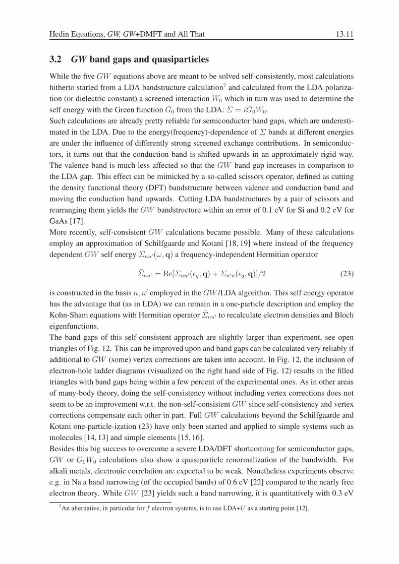
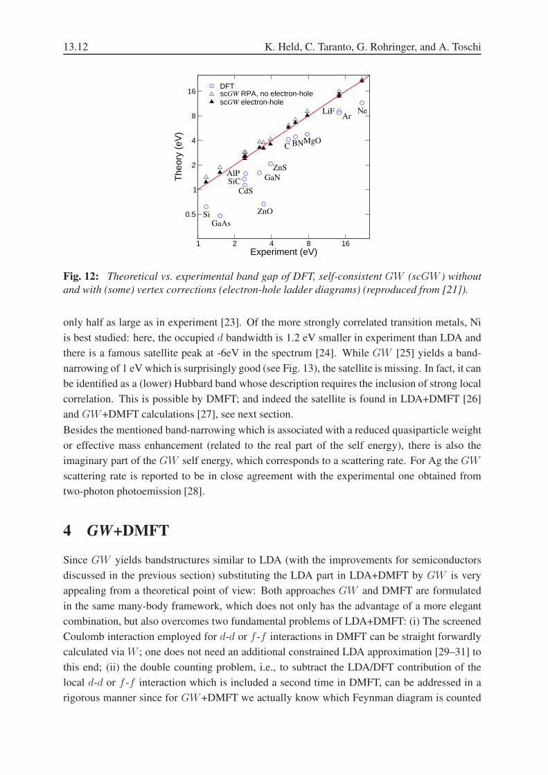
The band gaps of this self-consistent approach are slightly larger than experiment, see open
triangles of Fig. 12. This can be improved upon and band gaps can be calculated very reliably if
additional to GW (some) vertex corrections are taken into account. In Fig. 12, the inclusion of
electron-hole ladder diagrams (visualized on the right hand side of Fig. 12) results in the filled
triangles with band gaps being within a few percent of the experimental ones. As in other areas
of many-body theory, doing the self-consistency without including vertex corrections does not
seem to be an improvement w.r.t. the non-self-consistent GW since self-consistency and vertex
corrections compensate each other in part. Full GW calculations beyond the Schilfgaarde and
Kotani one-particle-ization (23) have only been started and applied to simple systems such as
molecules [14, 13] and simple elements [15, 16].
Besides this big success to overcome a severe LDA/DFT shortcoming for semiconductor gaps,
GW or G0W0 calculations also show a quasiparticle renormalization of the bandwidth. For
alkali metals, electronic correlation are expected to be weak. Nonetheless experiments observe
e.g. in Na a band narrowing (of the occupied bands) of 0.6 eV [22] compared to the nearly free
electron theory. While GW [23] yields such a band narrowing, it is quantitatively with 0.3 eV
7An alternative, in particular for f electron systems, is to use LDA+U as a starting point [12].
13.12 K. Held, C. Taranto, G. Rohringer, and A. Toschi
1 2 4 8 16Experiment (eV)
0.5
1
2
4
8
16
The
ory
(eV
)
DFTscGW RPA, no electron-holescGW electron-hole
Si
SiC
CdS
ZnO
C BN
GaAs
MgO
LiFAr
Ne
ZnS
GaNAlP
Fig. 12: Theoretical vs. experimental band gap of DFT, self-consistent GW (scGW ) without
and with (some) vertex corrections (electron-hole ladder diagrams) (reproduced from [21]).
only half as large as in experiment [23]. Of the more strongly correlated transition metals, Ni
is best studied: here, the occupied d bandwidth is 1.2 eV smaller in experiment than LDA and
there is a famous satellite peak at -6eV in the spectrum [24]. While GW [25] yields a band-
narrowing of 1 eV which is surprisingly good (see Fig. 13), the satellite is missing. In fact, it can
be identified as a (lower) Hubbard band whose description requires the inclusion of strong local
correlation. This is possible by DMFT; and indeed the satellite is found in LDA+DMFT [26]
and GW+DMFT calculations [27], see next section.
Besides the mentioned band-narrowing which is associated with a reduced quasiparticle weight
or effective mass enhancement (related to the real part of the self energy), there is also the
imaginary part of the GW self energy, which corresponds to a scattering rate. For Ag the GW
scattering rate is reported to be in close agreement with the experimental one obtained from
two-photon photoemission [28].
4 GW+DMFT
Since GW yields bandstructures similar to LDA (with the improvements for semiconductors
discussed in the previous section) substituting the LDA part in LDA+DMFT by GW is very
appealing from a theoretical point of view: Both approaches GW and DMFT are formulated
in the same many-body framework, which does not only has the advantage of a more elegant
combination, but also overcomes two fundamental problems of LDA+DMFT: (i) The screened
Coulomb interaction employed for d-d or f -f interactions in DMFT can be straight forwardly
calculated via W ; one does not need an additional constrained LDA approximation [29–31] to
this end; (ii) the double counting problem, i.e., to subtract the LDA/DFT contribution of the
local d-d or f -f interaction which is included a second time in DMFT, can be addressed in a
rigorous manner since for GW+DMFT we actually know which Feynman diagram is counted

Hedin Equations, GW, GW+DMFT and All That 13.13
Fig. 13: Experimental, LDA and GW bandstructure of Ni (reproduced from [25]).
DMFT +
++
=
all irreduciblelocal diagrams
Fig. 14: The DMFT self energy is calculated from the local contribution of all (one-particle
irreducible) Feynman diagrams.
twice.
Biermann et al. [27] proposed GW+DMFT, which they discuss from a functional integral point
of view: a GW functional and a local impurity functional are added; the derivatives yield the
mixed GW+DMFT equations. From a Feynman diagrammatic point of view, this corresponds
to adding the GW self energy, Fig. 1 and the DMFT self energy which is just given by the
local contribution of all (one-particle irreducible) Feynman diagrams, see Fig. 14. From these,
the local screened exchange GW and the doubly counted Hartree term need obviously to be
explicitly subtracted for not counting any diagram twice.
This results in the algorithm Fig. 15. Here, we leave the short-hand notation of Section 2 and
3.1 with 1, 2 since GW is diagonal in ω and k and DMFT is diagonal in ω and site indices. Let
us briefly discuss the GW+DMFT algorithm step-by-step; for more details see [32]:
• In most GW calculations, the starting point is a conventional LDA calculation (or another
suitably chosen generalized Kohn-Sham calculation), yielding an electron density ρ(r),
bandstructure ǫLDA(k) and also an LDA Green function Gk(ω) (the latter is calculated as
13.14 K. Held, C. Taranto, G. Rohringer, and A. Toschi
Do LDA calculation, yielding Gk(ω)=[ω1+µ1−ǫLDA(k)]−1.
Calculate GW polarization P GW(ω)=−2i∫
dω′
2π G(ω + ω′)G(ω′) .
If DMFT polarization P DMFT is known (after the 1st iteration), include it
P GW+DMFT(k, ω)=P GW(k, ω)−1
VBZ
∫
d3kP GW(k, ω) +P DMFT(ω) .
With this polarization, calculate the screened interaction:
W (k;ω) = Vee(k)[1− Vee(k)P (k;ω)]−1.
Calculate ΣHartreek =
∫d3qVBZ
Gq(τ=0−)W (k − q, 0) and ΣHartreedc .
Calculate ΣGW (r, r′;ω) = i∫
dω′
2π G(r, r′;ω + ω′)W (r, r′;ω′) .
Calculate the DMFT self-energy ΣDMFT and polarization P DMFT as follows:
From the local Green function G and old self-energy ΣDMFT calculate
(G0)−1(ω)=G−1(ω)+ΣDMFT(ω) ΣDMFT=0 in 1st iteration.
Extract the local screening contributions from W :
U(ω) = [W−1(ω)− P DMFT(ω)]−1.
With U and G0, solve impurity problem with effective action
A=∑
νσ lm
ψσ∗νm(Gσ0
νmn)−1ψσ
νn+∑
lmσσ′
∫
dτψσ∗l (τ)ψσ
l (τ)Ulm(τ−τ ′)ψσ′∗m (τ ′)ψσ′
m (τ ′),
resulting in G and susceptibility χ.
From G and χ, calculate ΣDMFT(ω) = (G0)−1(ω)−G−1(ω),
P DMFT(ω) = U−1(ω)− [U −UχU ]−1(ω).
Combine this to the total GW self-energy:
ΣGW+DMFT(k,ω)=ΣGW(k, ω)−
∫
d3kΣGW(k,ω)+ΣHartree(k)−ΣHartreedc +ΣDMFT(ω).
From this and G0, calculate Gnewk (ω)−1 = G0
k(ω)−1 −Σk(ω).
Iterate with Gk = Gnewk until convergence, i.e. ||Gk −Gnew
k ||<ǫ.
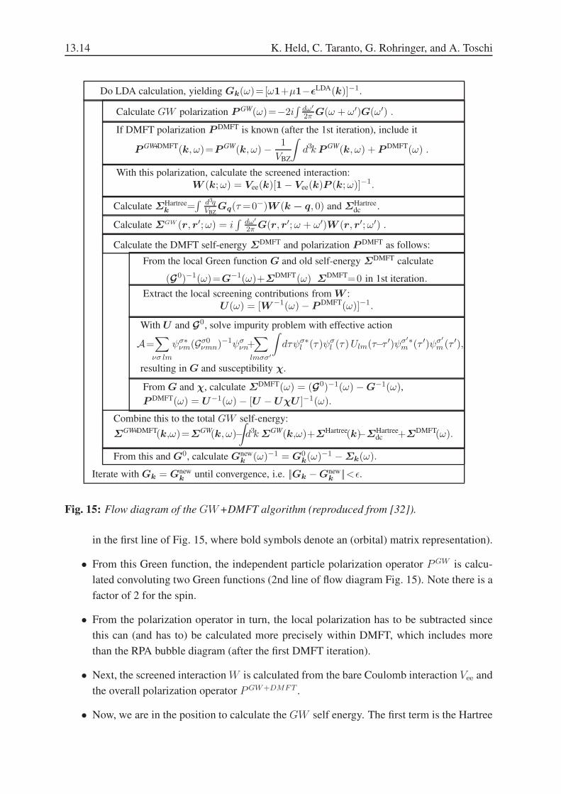
Fig. 15: Flow diagram of the GW+DMFT algorithm (reproduced from [32]).
in the first line of Fig. 15, where bold symbols denote an (orbital) matrix representation).
• From this Green function, the independent particle polarization operator PGW is calcu-
lated convoluting two Green functions (2nd line of flow diagram Fig. 15). Note there is a
factor of 2 for the spin.
• From the polarization operator in turn, the local polarization has to be subtracted since
this can (and has to) be calculated more precisely within DMFT, which includes more
than the RPA bubble diagram (after the first DMFT iteration).
• Next, the screened interaction W is calculated from the bare Coulomb interaction Vee and
the overall polarization operator PGW+DMFT .
• Now, we are in the position to calculate the GW self energy. The first term is the Hartree

Hedin Equations, GW, GW+DMFT and All That 13.15
diagram, which can be calculated straight forwardly in imaginary time τ , yieldingΣHartree
and the corresponding local contribution ΣHartreedc , which we need to subtract later to avoid
a double counting as it is also contained in the DMFT.
• The second diagram is the exchange from Fig. 1 which has the form G times W for the
GW self energy.
• This GW self energy has to be supplemented by the local DMFT self energy, which
together with the DMFT polarization operator is calculated in the following four steps:
1. The non-interacting Green function G0 which defines a corresponding Anderson
impurity model is calculated.
2. The local (screened) Coulomb interaction U(ω) has to be determined without the
local screening contribution, since the local screening will be again included in the
DMFT. That is we have to “unscreen” W for these contributions.
3. The Anderson impurity model defined by G0 and U(ω) has to be solved for its
interacting Green function G(ω) and two-particle charge susceptibility χ. This is
numerically certainly the most demanding step.
4. From this G(ω) and G0, we obtain a new DMFT self energy Σ(ω) and from the
charge susceptibility a new DMFT polarization operator.
• All three terms of the self-energy have now to be added; and the local screened exchange
and Hartree contribution need to be subtracted to avoid a double counting.
• From this GW+DMFT self energy we can finally recalculate the Green function and
iterate until convergence.
The flow diagram already shows that the GW+DMFT approach is much more involved than
LDA+DMFT. However, it has the advantage that the double counting problem is solved and
also the Coulomb interaction is calculated ab initio in a well defined and controlled way. Hence,
no ad hoc formulas or parameters need to be introduced or adjusted.
For defining a well defined interface between GW and DMFT a particular problem is that GW
is naturally formulated in real or k space and is presently implemented, e.g., in the LMTO [5]
or PAW basis [20]. However, on the DMFT side we do need to identify the interacting local d-
or f -orbitals on the sites of the transition metal or rare earth/lanthanoid sites, respectively. The
switching between these two representations is non-trivial. It can be done by a downfolding
[33, 34] or a projection onto Wannier orbitals, e.g., using maximally localized Wannier orbitals
[35, 37] or a simpler projection onto the d (or f ) part of the wave function within the atomic
spheres [36, 38]. However, not only the one-particle wave functions and dispersion relation
need to be projected onto the interacting subspace but also the interaction itself. To approach
the latter, a constrained random phase approximation (cRPA) method has been proposed [39,7]
and improved by disentangling the d(or f )-bands [40]. The latter improvement now actually
13.16 K. Held, C. Taranto, G. Rohringer, and A. Toschi
-8 -6 -4 -2 0 20
1
2
De
nsity o
f sta
tes
(e
V)
-1
Energy ( eV)
0
2
4
6
−10 −5 0 50
2
4
6
5Energy (eV)
ρ(E)
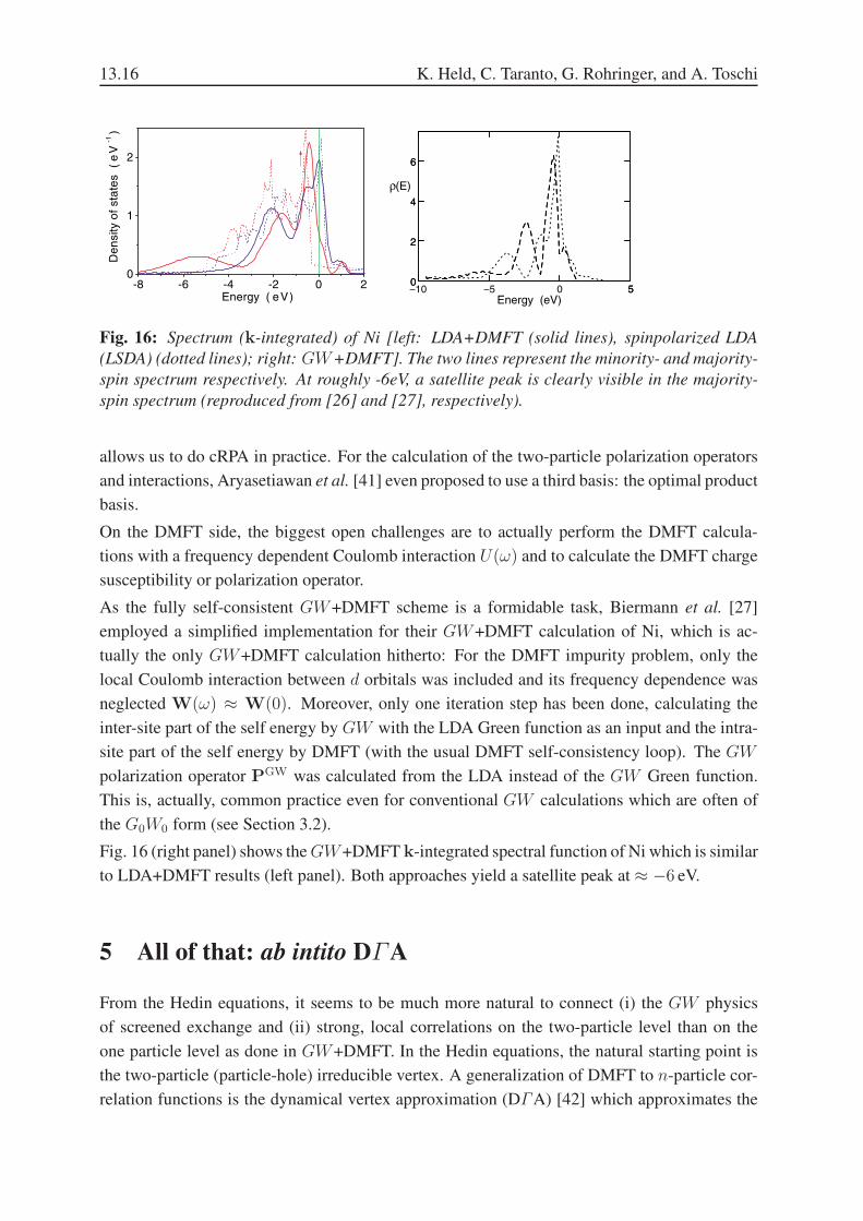
Fig. 16: Spectrum (k-integrated) of Ni [left: LDA+DMFT (solid lines), spinpolarized LDA
(LSDA) (dotted lines); right: GW+DMFT]. The two lines represent the minority- and majority-
spin spectrum respectively. At roughly -6eV, a satellite peak is clearly visible in the majority-
spin spectrum (reproduced from [26] and [27], respectively).
allows us to do cRPA in practice. For the calculation of the two-particle polarization operators
and interactions, Aryasetiawan et al. [41] even proposed to use a third basis: the optimal product
basis.
On the DMFT side, the biggest open challenges are to actually perform the DMFT calcula-
tions with a frequency dependent Coulomb interaction U(ω) and to calculate the DMFT charge
susceptibility or polarization operator.
As the fully self-consistent GW+DMFT scheme is a formidable task, Biermann et al. [27]
employed a simplified implementation for their GW+DMFT calculation of Ni, which is ac-
tually the only GW+DMFT calculation hitherto: For the DMFT impurity problem, only the
local Coulomb interaction between d orbitals was included and its frequency dependence was
neglected W(ω) ≈ W(0). Moreover, only one iteration step has been done, calculating the
inter-site part of the self energy by GW with the LDA Green function as an input and the intra-
site part of the self energy by DMFT (with the usual DMFT self-consistency loop). The GW
polarization operator PGW was calculated from the LDA instead of the GW Green function.
This is, actually, common practice even for conventional GW calculations which are often of
the G0W0 form (see Section 3.2).
Fig. 16 (right panel) shows theGW+DMFT k-integrated spectral function of Ni which is similar
to LDA+DMFT results (left panel). Both approaches yield a satellite peak at ≈ −6 eV.
5 All of that: ab intito DΓA
From the Hedin equations, it seems to be much more natural to connect (i) the GW physics
of screened exchange and (ii) strong, local correlations on the two-particle level than on the
one particle level as done in GW+DMFT. In the Hedin equations, the natural starting point is
the two-particle (particle-hole) irreducible vertex. A generalization of DMFT to n-particle cor-
relation functions is the dynamical vertex approximation (DΓA) [42] which approximates the
Hedin Equations, GW, GW+DMFT and All That 13.17
i i
i i
ii
i i
ir
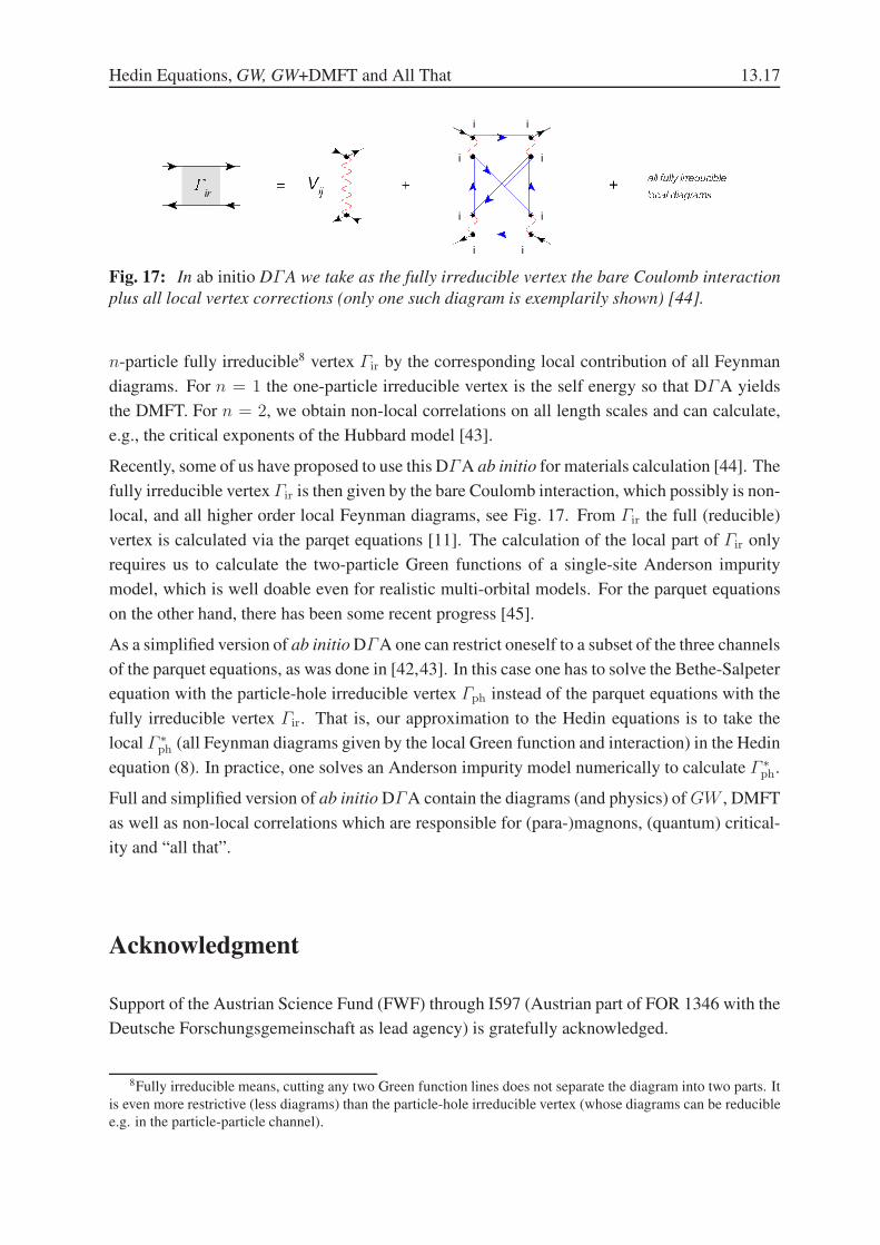
Fig. 17: In ab initio DΓA we take as the fully irreducible vertex the bare Coulomb interaction
plus all local vertex corrections (only one such diagram is exemplarily shown) [44].
n-particle fully irreducible8 vertex Γir by the corresponding local contribution of all Feynman
diagrams. For n = 1 the one-particle irreducible vertex is the self energy so that DΓA yields
the DMFT. For n = 2, we obtain non-local correlations on all length scales and can calculate,
e.g., the critical exponents of the Hubbard model [43].
Recently, some of us have proposed to use this DΓA ab initio for materials calculation [44]. The
fully irreducible vertex Γir is then given by the bare Coulomb interaction, which possibly is non-
local, and all higher order local Feynman diagrams, see Fig. 17. From Γir the full (reducible)
vertex is calculated via the parqet equations [11]. The calculation of the local part of Γir only
requires us to calculate the two-particle Green functions of a single-site Anderson impurity
model, which is well doable even for realistic multi-orbital models. For the parquet equations
on the other hand, there has been some recent progress [45].
As a simplified version of ab initio DΓA one can restrict oneself to a subset of the three channels
of the parquet equations, as was done in [42,43]. In this case one has to solve the Bethe-Salpeter
equation with the particle-hole irreducible vertex Γph instead of the parquet equations with the
fully irreducible vertex Γir. That is, our approximation to the Hedin equations is to take the
local Γ ∗ph (all Feynman diagrams given by the local Green function and interaction) in the Hedin
equation (8). In practice, one solves an Anderson impurity model numerically to calculate Γ ∗ph.
Full and simplified version of ab initio DΓA contain the diagrams (and physics) of GW , DMFT
as well as non-local correlations which are responsible for (para-)magnons, (quantum) critical-
ity and “all that”.
Acknowledgment
Support of the Austrian Science Fund (FWF) through I597 (Austrian part of FOR 1346 with the
Deutsche Forschungsgemeinschaft as lead agency) is gratefully acknowledged.
8Fully irreducible means, cutting any two Green function lines does not separate the diagram into two parts. It
is even more restrictive (less diagrams) than the particle-hole irreducible vertex (whose diagrams can be reducible
e.g. in the particle-particle channel).

13.18 K. Held, C. Taranto, G. Rohringer, and A. Toschi
Appendices
A Additional steps: equation of motion
In this appendix a detailed explanation is given how to derive the Hedin equation of motion for
Σ, i.e., equation (16), from the standard equation of motion (15). In a first step Γ is expressed
in terms of Γ ∗. In order to keep the notation simple, the arguments of all functions are omitted
and the functions are considered as operators.
The starting point of the calculations are the Bethe-Salpeter equations for Γ and Γ ∗:
Γ = Γph + ΓβGGΓph =⇒ Γ = Γph(1− βGGΓph)−1
Γ ∗ = Γ ∗ph + Γ ∗
phβGGΓ ∗ =⇒ Γ ∗ph = Γ ∗(1 + βGGΓ ∗)−1.
(24)
Using equation (10), i.e., Γph = Γ ∗ph + V , one gets:
Γ =
(
Γ ∗(1 + βGGΓ ∗)−1 + V
)1
1− βGG
(
Γ ∗(1 + βGGΓ ∗)−1 + V
) (25)
Multiplying this equation with 1 = (1 + βGGΓ ∗)−1(1 + βGGΓ ∗) and using the standard
relations for operators, A−1B−1 = (BA)−1 leads to:
Γ =
(
Γ ∗(1 + βGGΓ ∗)−1 + V
)
V −1V︸ ︷︷ ︸
1
(
1− (βGG+ βGGΓ ∗βGG︸ ︷︷ ︸
P
)V
)−1(
1 + βGGΓ ∗
)
,
(26)
where 1 = V −1V was inserted and the definition for the polarization operator, equation (7).
Now one can use the second Hedin equation (6), which can be rewritten as W = V (1−PV )−1.
Inserting this relation into the equation for Γ , one arrives at the following result:
Γ =
(
Γ ∗(1 + βGGΓ ∗)−1
)
V −1W
(
1 + βGGΓ ∗
)
+W
(
1 + βGGΓ ∗
)
. (27)
Another formulation of the second Hedin equation gives V −1 = W−1 + P = W−1 + (1 +
βGGΓ ∗)βGG. Replacing V −1 by this expression gives:
Γ = Γ ∗ + Γ ∗βGGW (1 + βGGΓ ∗) +W (1 + βGGΓ ∗)
= Γ ∗ + Γ ∗βGGW + Γ ∗βGGWβGGΓ ∗ +WβGGΓ ∗ +W .(28)
This equation shows how the full Γ is related to the Γ ∗. Diagrammatically this relation is shown
in Fig. 18.
In the next step Γ as given in equation (28) is inserted into equation (15), yielding
Σ = −GV βGGΓ −GV
= −GV (βGG+ βGGΓ ∗βGG︸ ︷︷ ︸
P
)W −GV((βGG+ βGGΓ ∗βGG︸ ︷︷ ︸
P
)W + 1)βGGΓ ∗ −GV .
(29)
Hedin Equations, GW, GW+DMFT and All That 13.19
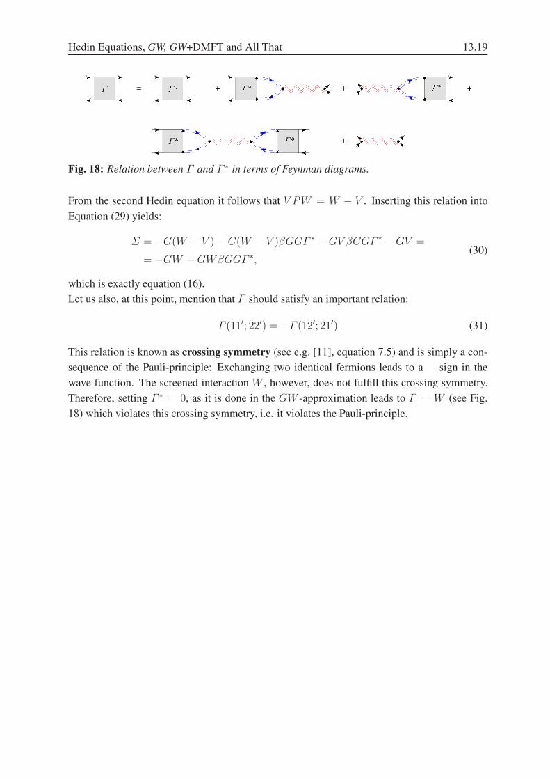
Fig. 18: Relation between Γ and Γ ∗ in terms of Feynman diagrams.
From the second Hedin equation it follows that V PW = W − V . Inserting this relation into
Equation (29) yields:
Σ = −G(W − V )−G(W − V )βGGΓ ∗ −GV βGGΓ ∗ −GV =
= −GW −GWβGGΓ ∗,(30)
which is exactly equation (16).
Let us also, at this point, mention that Γ should satisfy an important relation:
Γ (11′; 22′) = −Γ (12′; 21′) (31)
This relation is known as crossing symmetry (see e.g. [11], equation 7.5) and is simply a con-
sequence of the Pauli-principle: Exchanging two identical fermions leads to a − sign in the
wave function. The screened interaction W , however, does not fulfill this crossing symmetry.
Therefore, setting Γ ∗ = 0, as it is done in the GW -approximation leads to Γ = W (see Fig.
18) which violates this crossing symmetry, i.e. it violates the Pauli-principle.

13.20 K. Held, C. Taranto, G. Rohringer, and A. Toschi
References
[1] P. Hohenberg and W. Kohn, Phys. Rev. 136 B864 (1964)
[2] R. O. Jones and O. Gunnarsson, Rev. Mod. Phys. 61 689 (1989)
[3] See Lecture notes of P. Blochl.
[4] L. Hedin, Phys. Rev. A 139 796 (1965)
[5] For a review see, F. Aryasetiawn and O. Gunnarsson, Rep. Prog. Phys. 61 237 (1998)
[6] A. A. Abrikosov, L. P. Gorkov and I. E. Dzyaloshinski, Methods of Quantum Field Theory
in Statistical Physics (Dover, New York, 1963)
[7] For more details on RPA, see Lecture notes of F. Aryasetiawan
[8] W. Metzner and D. Vollhardt, Phys. Rev. Lett. 62 324 (1989)
[9] A. Georges, G. Kotliar, W. Krauth and M. Rozenberg, Rev. Mod. Phys. 68 13 (1996)
[10] For more details on DMFT, see Lecture notes of M. Kollar
[11] N. E. Bickers, “Self consistent Many-Body Theory of Condensed Matter” in Theoretical
Methods for Strongly Correlated Electrons CRM Series in Mathematical Physics Part III,
Springer (New York 2004)
[12] H. Jiang and R. Gomez-Abal and P. Rinke and M. Scheffler, Phys. Rev. Lett. 102, 126403
(2009); Phys. Rev. B 82, 045108 (2010)
[13] A. Stan, N. E. Dahlen, and R. van Leeuwen, J. Chem. Phys. 130, 114105 (2009)
[14] C. Rostgaard, K. W. and Jacobsen, and K. S. Thygesen Phys. Rev. B 81, 085103 (2010)
[15] W.-D. Schone and A. G. Eguiluz, Phys. Rev. Lett. 81, 1662 (1998)
[16] A. Kutepov, S. Y. Savrasov, G. and Kotliar, Phys. Rev. B 80, 041103 (2009)
[17] R. W. Godby, M. Schluter and L. J. Sham, Pyhs. Rev. B 37 10159 (1988)
[18] S. V. Faleev, M. van Schilfgaarde, and T. Kotani, Phys. Rev. Lett. 93, 126406 (2004)
[19] A. N. Chantis, M. van Schilfgaarde, and T. Kotani, Phys. Rev. Lett. 96, 086405 (2006)
[20] M. Shishkin and G. Kresse, Phys. Rev. B 74, 035101 (2006)
[21] M. Shishkin, M. Marsman, and G. Kresse, Phys. Rev. Lett. 99, 246403 (2007)
[22] I.-W. Lyo and W. E. Plummer, Phys. Rev. Lett. 60, 1558 (1988)
Hedin Equations, GW, GW+DMFT and All That 13.21
[23] J. E. Northrup, M. S. Hybertsen, and S. G. Louie, Phys. Rev. Lett. 59 819 (1987);
Phys. Rev. B 39, 8198 (1989)
[24] S. Hufner, G. K. Wertheim, N. V. Smith, and M. M. Traum,
Solid State Comm. 11 323 (1972)
[25] F. Aryasetiawan, Phys. Rev. B 46, 13051 (1972)
[26] A. I. Lichtenstein, M. I. Katsnelson, and G. Kotliar, Phys. Rev. Lett. 87 67205 (2001)
[27] S. Biermann, F. Aryasetiawan, and A. Georges, Phys. Rev. Lett. 90 086402 (2003)
[28] R. Keyling, W.-D.Schone, and W. Ekardt, Phys. Rev. B 61, 1670 (2000)
[29] P. H. Dederichs, S. Blugel, R. Zeller and H. Akai, Phys. Rev. Lett. 53 2512 (1984)
[30] A. K. McMahan, R. M. Martin and S. Satpathy, Phys. Rev. B 38 6650 (1988)
[31] O. Gunnarsson, O. K. Andersen, O. Jepsen and J. Zaanen, Phys. Rev. B 39 1708 (1989)
[32] K. Held, Advances in Physics 56, 829 (2007)
[33] O. K. Andersen, T. Saha-Dasgupta, R. W. Tank, C. Arcangeli, O. Jepsen and G. Krier, In
Lecture notes in Physics, edited by H. Dreysse (Springer, Berlin, 1999)
[34] O. K. Andersen, T. Saha-Dasgupta, S. Ezhov, L. Tsetseris, O. Jepsen, R. W. Tank and
C. A. G. Krier, Psi-k Newsletter # 45 86 (2001),
http://psi-k.dl.ac.uk/newsletters/News_45/Highlight_45.pdf
[35] N. Marzari and D. Vanderbilt, Phys. Rev. B 56 12847 (1997)
[36] V.I. Anisimov, D.E. Kondakov, A.V. Kozhevnikov, I.A. Nekrasov, Z.V. Pchelkina, J.W.
Allen, S.-K. Mo, H.-D. Kim, P. Metcalf, S. Suga, A. Sekiyama, G. Keller, I. Leonov, X.
Ren, D. Vollhardt, Phys. Rev. B 71, 125119 (2005)
[37] J. Kunes, R. Arita, P. Wissgott, A. Toschi, H. Ikeda, and K. Held, Comp. Phys. Comm.
181, 1888 (2010)
[38] M. Aichhorn, L. Pourovskii, V. Vildosola, M. Ferrero, O. Parcollet, T. Miyake, A. Georges,
and S. Biermann Phys. Rev. B 80, 085101 (2009)
[39] F. Aryasetiawan, M. Imada, A. Georges, G, Kotliar, S. Biermann and A.I. Lichtenstein,
Phys. Rev. B 70, 195104 (2004)
[40] T. Miyake, F. Aryasetiawan, M. Imada, arXiv:0906.1344
[41] F. Aryasetiawan, S. Biermann and A. Georges, In Proceedings of the conference on ”Co-
incidence Studies of Surfaces, Thin Films and Nanostructures”, edited by A. Gonis
(Wiley, New York, 2004)
13.22 K. Held, C. Taranto, G. Rohringer, and A. Toschi
[42] A. Toschi, A.A. Katanin and K. Held, Phys. Rev. B 75, 045118 (2007);
Prog. Theor. Phys. Suppl. 176, 117 (2008); Phys. Rev. B 80, 075104 (2009)
[43] G. Rohringer, A. Toschi, A.A. Katanin and K. Held arxiv.org/abs/1104.1919
[44] A. Toschi, G. Rohringer, A. A. Katanin, K. Held arxiv.org/abs/1104.2118
[45] S.-X. Yang, H. Fotso, J. Liu, T. A. Maier, K. Tomko, E.F. D’Azevedo, R.T. Scaletar,
T. Pruschke, M. Jarrell, Phys. Rev. E 80, 046706 (2009)


