
User's Guide
Version 1.0 Sept. 2002


i
CTC Union Technologies Co., Ltd. Far Eastern Vienna Technology Center 8F, No. 60, ZhouZi Street NeiHu, Taipei, 114 Taiwan HCT-BERT/H E1/T1/Datacom Bit Error Rate Tester, User's Guide Version 1.0 September 2002 Printing This manual supports the following models: HCT-BERT/H
The information contained in this document is subject to change without prior notice.

ii

HCT-BERT/H E1/T1/Datacom Bit Error Rate Tester Table of Contents
iii
Chapter 1: E1/T1 Technology Overview 1.1 E1/T1 Brief History ………………………………………. 1 1.2 Technical Standards ……………………………………… 8 1.3 Pulse Code Modulation …………………………………… 9 1.4 Line Coding ………………………………………………. 10 1.5 Framing …………………………………………………… 10 1.6 CRC ……………………………………………………….. 12 Chapter 2: HCT-BERT/H Overview 2.1 Introduction ………………………………………………... 17 2.2 Functions …………………………………………………... 17 2.3 General Specifications ……………………………………... 18 2.4 Status LEDs …………………………………..…………… 26 2.5 Rear Panel …………………………………………………. 32 Chapter 3: The Keyboard 3.1 Introduction ……………………………………………….. 39 3.2 Keyboard Figure ………………………………………….. 40 3.3 Key Function ……………………………………………… 41 Chapter 4: General Operation 4.1 HCT-BERT/H Power Up ………………………………… 47 4.2 HCT-BERT/H Menu System …………………………….. 48 4.3 System Reset ……………………………………………… 50 4.4 Back light Toggle …………………………………………. 50 4.5 Examine Analysis …………………………………………. 50 Chapter 5: Configuration Setup 5.1 Configuration Setup ……………………………………….. 52 5.2 Parameter Details ………………………………………….. 53 5.3 Auto-Configuration ……………………………………….. 67

HCT-BERT/H E1/T1/Datacom Bit Error Rate Tester Table of Contents
iv
Chapter 6: BERT Analysis 6.1 Introduction ……………………………………………….. 68 6.2 Performance ………………………………………………. 73 6.3 Histogram …………………………………………………. 76 6.4 Function Keys …………………………………………….. 81 Chapter 7: Alarms and Loopback 7.1 Alarms and Loopback ……………………………………. 88 7.2 Alarm Setting …………………………………………….. 88 7.3 Loopback Setting …………………………………………. 91 Chapter 8: Signal Result 8.1 Signal Result …………………………………………….. 94 Chapter 9: Signaling Setup 9.1 Signaling Setup …………………………………………… 96 Chapter 10: Signaling Display 10.1 Signaling Display ………………………………………… 98 Chapter 11: Remote Port Setup 11.1 Introduction ………………………………………………. 100 11.2 Remote Port Setup ………………………………….......... 101 11.3 Operation ………………………………………………… 102 11.4 Commands ……………………………………………….. 109 Chapter 12: User Program Pattern 12.1 Introduction ……………………………………………. 117 12.2 Operation …………………………………………….. 118 Chapter 13: Time Slot Setting 13.1 Introduction …………………………………………….. 119 13.2 Operation ………………………………………………. 121

HCT-BERT/H E1/T1/Datacom Bit Error Rate Tester Table of Contents
v
Chapter 14: Time Slot Map Data 14.1 Operation ………………………………………………… 123 Chapter 15: File Management 15.1 Introduction ………………………………………………. 125 15.2 Operation …………………………………………………. 125 Chapter 16: Miscellaneous 16.1 Description ……………………………………………….. 127 16.2 Key Sound Setup …………………………………………. 127 16.3 Print function setting ……………………………………… 128 16.4 Clock Setup ………………………………………………. 128 16.5 Version Display ………………………………………….. 129 Chapter 17: Self Test 17.1 Description ……………………………………………..… 131 17.2 Self Test Single Mode ……………………………………. 131 17.3 Self Test Continuous Mode ……………………………… 132 17.4 Print Port Test ……………………………………………. 132 17.5 LCD Test …………………………………………………. 133 17.6 Keyboard Test ……………………………………………. 133 Chapter 18: Sa Bits Setup 18.1 Introduction ………………………………………………. 135 18.2 Sa Bits Transmission Setting …………………………….. 136 18.3 Sa bits Monitor …………………………………………… 137 Chapter 19: Datacom BERT 19.1 Introduction ………………………………………………. 139 19.2 Configuration Setup ………………………………………. 139 19.3 Clock setting ………………………………………………. 144 19.4 Datacom BERT Analysis …………………………………. 145 19.5 Performance ………………………………………………. 146 19.6 Function Keys …………………………………………….. 147

HCT-BERT/H E1/T1/Datacom Bit Error Rate Tester Table of Contents
vi
Chapter 20: Low Speed Datacom BERT 20.1 Low Speed Datacom BERT SETUP……..……...........…. 151 20.2 Running Low Speed Datacom BERT ……..........……….. 155 Appendix A: Acronyms and Abbreviations ………………… 159 Appendix B: Cable Pin Out …………………………………. 163

HCT-BERT/H E1/T1/Datacom Bit Error Rate Tester Chapter 1: E1/T1 Technology Overview
1
1.1 E1/T1 Brief History E1/T1 technology has its roots in the original AT&T T1 public telephone networks. The AT&T T1 carrier used PCM (Pulse Code Modulation) and time-division multiplexing over wire pairs with digital repeaters spaced 6000 feet apart. The 24 speech channels were encoded on the 1.544 Mbps bit stream. Seven bits were used for encoding each sample. The system was designed to transmit voice frequencies up to 4 kHz, and therefore required sampling at 8000 samples per second. Each frame was 125 usec. There are a total of 193 bits in each frame, giving 193 x 8000 = 1.544 Mbps. When T1 facilities were first introduced by AT&T, they were installed mainly in the public telephone network to implement connections between switching offices. The T1 carrier has become so successful that individual users of telecommunications can now lease T1 facilities from a variety of common carriers and are routinely used to implement communication links where high data rates are required. The T1 carrier remains as the accepted standard for North America, and the Digital Service (DS1) metallic interface has been further defined by the American National Standards Institute under ANSI T1.403-1995. The ANSI recommendation for Digital Services differs slightly from the original standard set by AT&T. It employs a 193 bit frame with 8 bits per channel timeslot. The frame alignment bit is the first bit. Twenty-four timeslots make up the frame. A superframe (SF) consists of twelve consecutive frames. An extended superframe (ESF) consists of twenty-four consecutive frames. Figure 1-1 shows both the superframe (SF) and extended superframe (ESF) formats.

HCT-BERT/H E1/T1/Datacom Bit Error Rate Tester Chapter 1: E1/T1 Technology Overview
2
Channel time slot (8 bits) Frame (193 bits) Superframe (12 frames)
Fig. 1-1(a) ANSI Superframe bit assignment Channel time slot (8 bits) Frame (193 bits) Extended Superframe (24 frames)
Fig. 1-1(b) ANSI Extended Superframe bit assignment
BIT 2
BIT 3
BIT 4
BIT 5
BIT 6
BIT 1
BIT 7
BIT 8
TS 1
TS 2
TS 3
TS 4
TS 5
TS 24
F
FR 1
FR 2
FR 3
FR 4
FR 5
FR 12
BIT 2
BIT 3
BIT 4
BIT 5
BIT 6
BIT 1
BIT 7
BIT 8
TS 1
TS 2
TS 3
TS 4
TS 5
TS 24
F
FR 1
FR 2
FR 3
FR 4
FR 5
FR 24

HCT-BERT/H E1/T1/Datacom Bit Error Rate Tester Chapter 1: E1/T1 Technology Overview
3
Superframe Format (SF, D4) The Superframe Format (SF), is also referred to as the D4 format. The requirement for associated signaling in frames 6 and 12 dictates that the frames be distinguishable. This leads to a multiframe structure consisting of 12 frames per superframe (SF). See Figure 1-1 and Tables 1-1. The SF structure consists of a multiframe of 12 frames. Each frame has 24 channels, plus an F-bit, and 8 bits per channel. A channel is equivalent to one voice circuit or one 64 kbps data circuit. This structure of frames and multiframes is defined by the F-bit pattern. The F-bit is designated alternately as an Ft bit (terminal framing bit) or an Fs bit (signaling framing bit). The Ft bit carries a pattern of alternating zeros and ones (101010) in odd frames that defines the frame boundaries so that one channel may be distinguished from another. The Fs bit carries a pattern of (001110) in even frames, and defines the multiframe boundaries so that one frame may be distinguished from another. Table 1-1. Superframe Format (SF, D4)
Frame# Bit# F-Bits Bit Use in Each Time Slot
Signaling Channel
Terminal Framing Ft
Signaling Framing Fs
Traffic Sig
1 0 1 1-8 2 193 0 1-8 3 386 0 1-8 4 579 0 1-8 5 772 1 1-8 6 965 1 1-7 8 A 7 1158 0 1-8 8 1351 1 1-8 9 1544 1 1-8
10 1737 1 1-8 11 1930 0 1-8 12 2123 0 1-7 8 B

HCT-BERT/H E1/T1/Datacom Bit Error Rate Tester Chapter 1: E1/T1 Technology Overview
4
Extended Superframe Format (ESF) In Extended Superframe Format (ESF) Figure 1-2, and Table 1-2, the multiframe structure is extended to 24 frames. The channel structure is identical to D4 (SF) format. Robbed-bit signaling is accommodated in frame 6 (A-bit), frame 12 (B-bit), frame 18 (C-bit), and frame 24 (D-bit). The F-bit pattern of ESF contains three functions: 1 Framing Pattern Sequence (FPS), which defines the frame and
multiframe boundaries. 2 Facility Data Link (FDL), which allows data such as error
performance to be passed within the T1 link. 3 Cyclic Redundancy Check (CRC), which allows error performance
to be monitored and enhances the reliability of the receiver's framing algorithm.

HCT-BERT/H E1/T1/Datacom Bit Error Rate Tester Chapter 1: E1/T1 Technology Overview
5
Table 1-2. Extended Superframe Format (ESF)
F-Bits Frame# Bit# FPS DL CRC
Bit Use in Each Time Slot
Signaling Channel
1 0 - m - 1-8 2 193 - - C1 1-8 3 386 - m - 1-8 4 579 0 - - 1-8 5 772 - m - 1-8 6 965 - - C2 1-7 8 A A A 7 1158 - m - 1-8 8 1351 0 - - 1-8 9 1544 - m - 1-8
10 1737 - - C3 1-8 11 1930 - m - 1-8 12 2123 1 - - 1-7 8 B B A 13 2316 - m - 1-8 14 2509 - - C4 1-8 15 2702 - m - 1-8 16 2895 0 - - 1-8 17 3088 - m - 1-8 18 3281 - - C5 1-7 8 C A A 19 3474 - m - 1-8 20 3667 1 - - 1-8 21 3860 - m - 1-8 22 4053 - - C6 1-8 23 4246 m - 1-8 24 4439 1 - - 1-7 8 D B A
Notes: 1. FPS indicates the Framing Pattern Sequence (…001011…) 2. DL indicates the 4Kb/s Data Link with message bits m. 3. CRC indicates the cyclic redundancy check with bits C1 to C6. 4. Signaling options include 16 state, 4 state, and 2 state.
HCT-BERT/H E1/T1/Datacom Bit Error Rate Tester Chapter 1: E1/T1 Technology Overview
6
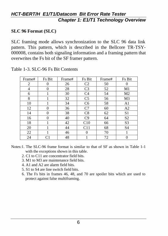
SLC 96 Format (SLC) SLC framing mode allows synchronization to the SLC 96 data link pattern. This pattern, which is described in the Bellcore TR-TSY-000008, contains both signaling information and a framing pattern that overwrites the Fs bit of the SF framer pattern. Table 1-3. SLC-96 Fs Bit Contents
Frame# Fs Bit Frame# Fs Bit Frame# Fs Bit 2 0 26 C2 50 0 4 0 28 C3 52 M1 6 1 30 C4 54 M2 8 1 32 C5 56 M3 10 1 34 C6 58 A1 12 0 36 C7 60 A2 14 0 38 C8 62 S1 16 0 40 C9 64 S2 18 1 42 C10 66 S3 20 1 44 C11 68 S4 22 1 46 0 70 1 24 C1 48 1 72 0
Notes:1. The SLC-96 frame format is similar to that of SF as shown in Table 1-1
with the exceptions shown in this table. 2. C1 to C11 are concentrator field bits. 3. M1 to M3 are maintenance field bits. 4. A1 and A2 are alarm field bits. 5. S1 to S4 are line switch field bits.
6. The Fs bits in frames 46, 48, and 70 are spoiler bits which are used to protect against false multiframing.

HCT-BERT/H E1/T1/Datacom Bit Error Rate Tester Chapter 1: E1/T1 Technology Overview
7
The ITU-T (formerly CCITT) has made two recommendations for PCM transmission which can be achieved over most telephone wire pairs, one for the T1 carrier speed of 1.544 Mbps and one for E1 transmission at 2.048 Mbps,. The ITU-T recommendation for 1.544 Mbps differs slightly from the North American standard set by AT&T. It employs a 193 bit frame with 8 bits per channel, and the frame alignment bit is the first bit, not the 193rd as in the AT&T standard. Sixteen frames of 256 bits each are grouped together to form one multi-frame. There are thirty-two 8-bit time slots in each frame, giving 30 speech channels of 64 Kbps each, one synchronization channel, and one signaling channel. 64 Kbps x 32 channels = 2.048 Mbps. Figure 1-2 shows the ITU-T 2.048 Mbps recommendation, which most of the world outside North America uses for PCM transmission.
The E1 frame structure:
Fig. 1-2 ITU-T E1 Frame Structure
HCT-BERT/H E1/T1/Datacom Bit Error Rate Tester Chapter 1: E1/T1 Technology Overview
8
1.2 Technical Standards E1 transmission technology is defined by a number of technology standards. The following standards cover many of the important aspects of E1 transmission technology:
ITU G.703 Physical/Electrical characteristics of interfaces ITU G.704 Synchronous frame structures ITU G.706 Frame alignment and CRC ITU G.821 Error performance of an international connection ITU G.826 Error performance and objectives for international ITU M.550/M.2100 Bringing an international connection into
service ITU Q.400 to Q.490 Specs for R2 Signaling Systems ITU Q.700 Series SS7 Specification ITU Q.921 and Q.931 ISDN Layer 2 and 3 protocol

HCT-BERT/H E1/T1/Datacom Bit Error Rate Tester Chapter 1: E1/T1 Technology Overview
9
1.3 Pulse Code Modulation To transmit voice in a digital medium, such as a 2.048 Mbps line, the analog voice signal must first be encoded into a binary format. The conversion is achieved via Pulse Code Modulation. For voice signals a maximum frequency of 4000 Hz provides adequate clarity while conserving transmission bandwidth. The Nyquist theorem requires that a signals maximum frequency be sampled at two times to reproduce the signal without loss of information. Therefore to achieve the 4000 Hz bandwidth, the analog signal is sampled at 8000 samples/second. The analog signal is first run through a compander (compression circuit) to raise the analog signals to their maximum level. Then the level at each of the samples is converted to an 8-bit word code. Referring to Figure 1-3 below, a 1 KHz sine wave is sampled at 8 KHz (8 samples per cycle) and yields a discrete 8-bit value at each sample point. The 8-bit words occurring at 8000 times per second form a 64 Kbps data bit stream.
Fig. 1-3 PCM Sampling Example

HCT-BERT/H E1/T1/Datacom Bit Error Rate Tester Chapter 1: E1/T1 Technology Overview
10
1.4 Line Coding There are two common types of line coding defined for use in an E1 network: AMI and HDB3
AMI AMI (Alternate Mark Inversion) is the simplest of the two line coding formats and is used to represent successive ones in a bit stream with alternating positive and negative pulses. A zero bit will not generate any pulse. AMI is not used in most E1 transmissions because of synchronization loss during long strings of data zeros.
HDB3 HDB3 coding was adopted to eliminate the synchronization problems occurring with AMI. In the HDB3 format, a string of four consecutive zeros is replaced with a substitute string containing an intentional BPV (Bi-Polar Violation). The receiving equipment then reads the code and reconstructs the original data. HDB3 code provides high pulse density so that receiving equipment is always able to maintain synchronization with the received signal. 1.5 Framing Framing is necessary so that receiving equipment is able to identify and extract the individual channels. E1 transmissions utilize two major types of framing: Frame Alignment Signal (FAS) and Multi-frame Alignment Signal (MFAS).
FAS The 2.048 Mbps frame consists of 32 individual time slots numbered 0 to 31. Each time slot consists of a 64 Kbps channel of data.

HCT-BERT/H E1/T1/Datacom Bit Error Rate Tester Chapter 1: E1/T1 Technology Overview
11
Time slot zero of every other frame is reserved for the FAS pattern. Alternate frames contain the FAS Distant Alarm indication bit. Data may be placed in the remaining 31 time slots. PCM-31 uses FAS.
One 2.048 Mbps frame time slot 0 1 …… 31
bits 1 2 3 4 5 6 7 8 Si 0 0 1 1 0 1 1 FAS frame Si 1 A Sn Sn Sn Sn Sn alternate frame
Figure 1-3 The FAS Frame Format Sn: bit reserved for national use Si: bit reserved for international use A: remote FAS Distant Alarm bit 0011011: frame alignment signal pattern MFAS (FAS+CAS) MFAS (Multi-Frame Alignment Signal) framing provides Channel Associated Signaling (CAS) to transmit ABCD bit supervision information for each channel. The MFAS method uses the 32 time slot frame format, including time slot 0 for FAS and time slot 16 for MFAS and CAS signaling. It takes 16 frames to make up a Multi-Frame. When the MFAS frame is transmitted, the individual FAS frames and framing information remains intact. Time slot 16 of the first frame contains the MFAS framing information. Time slot 16 of the remaining 15 frames of the Multi-Frame contain the ABCD bits. Refer to Figure 1-4 for the MFAS frame format.

HCT-BERT/H E1/T1/Datacom Bit Error Rate Tester Chapter 1: E1/T1 Technology Overview
12
Frame 0 Frame 1 Frame 2 Frame 3 …….. Frame 15
TS 0
… TS 16
… TS 31
TS 0
… TS 16
… TS 31
TS 0
… TS 16
… TS 31
BITS BITS BITS 1 2 3 4 5 6 7 8 1 2 3 4 5 6 7 8 1 2 3 4 5 6 7 8 0
0
0
0
X
Y
X
X
A B C D Channel 1 (Ts-1)
A B C D Channel 16 (Ts-17)
A B C D Channel 15 (Ts-15)
A B C D Channel 30 (Ts-31)
Figure 1-4 The MFAS Frame Format Frame 0 Time Slot 16: bits 0000XYXX X=spare bits (equals 1 if not used) Y=MFAS Remote Alarm (equals 1 if sync is lost) notes: 1) Frames are transmitted with 30 voice channels on TS1-15,17-31. 2) TS16 contains ABCD bits for signaling (CASS). 3) MFAS framing still includes the original FAS frames and framing information. 1.6 CRC-4 A Cyclic Redundancy Check-4 (CRC-4) is used in E1 transmission to identify possible bit errors. CRC-4 allows detection of errors within the 2.048 Mbps signal while in service. CRC-4 is based upon simple mathematical calculations performed on each sub multi-frame of data. The equipment which originates the E1 data calculates the CRC-4 bits for one sub multi-frame and inserts them into the CRC-4 positions of the next sub multi-frame. The receiving equipment then performs the reverse mathematical calculations on the sub multi-frame, examines the CRC-4 bits received in the next sub multi-frame, and then compares the received CRC-4 bits to the calculated value. If the values do not compare, a CRC-4 error is reported.

HCT-BERT/H E1/T1/Datacom Bit Error Rate Tester Chapter 1: E1/T1 Technology Overview
13
CRC-4 Notes: 1) A CRC-4 error does not necessarily indicate a single bit error. Multiple bit errors within the same sub multi-frame will only generate a single CRC-4 error for the block. 2) There is a remote possibility that the calculated and transmitted CRC-4 bits compare even though an error has occurred. Table 1-4. ITU-T CEPT Frame Format Timeslot 0 Bit Allocations
Time Slot 0 Bits 1 to 8 of each frame SMF Frame # 1 2 3 4 5 6 7 8 0 C1/Si 0 0 1 1 0 1 1 1 0/Si 1 A SA4 SA5 SA6 SA7 SA8 2 C2/Si 0 0 1 1 0 1 1 3 0/Si 1 A SA4 SA5 SA6 SA7 SA8 4 C3/Si 0 0 1 1 0 1 1 5 1/Si 1 A SA4 SA5 SA6 SA7 SA8 6 C4/Si 0 0 1 1 0 1 1
I
7 0/Si 1 A SA4 SA5 SA6 SA7 SA8 8 C1/Si 0 0 1 1 0 1 1 9 1/Si 1 A SA4 SA5 SA6 SA7 SA8
10 C2/Si 0 0 1 1 0 1 1 11 1/Si 1 A SA4 SA5 SA6 SA7 SA8 12 C3/Si 0 0 1 1 0 1 1 13 E/Si 1 A SA4 SA5 SA6 SA7 SA8 14 C4/Si 0 0 1 1 0 1 1
II
15 E/Si 1 A SA4 SA5 SA6 SA7 SA8 Notes:
1. SMF indicates the sub-multi-frame. This partitioning is used in the CRC-4 calculation. 2. Si bits are International Spare Bits. 3. A bit is used to indicate a remote alarm condition (active high). 4. SA4 to SA8 are spare bits that may be recommended by ITU-T for use in specific point-to-
point applications (e.g., transcoder equipment conforming to Recommendation G.761). 5. SA4 to SA8 where these are not used should be set to 1 on links crossing an international
border. 6. E bit is used to indicate a CRC-4 error. The normal state is both bits set to 1, when a CRC-4
error is detected one of the E bits is set to 0. 7. C1 to C4 bits are used to carry the CRC-4 code. 8. Timeslot 0 that contains the 0011011 sequence is defined as the FAS word and Timeslot 0 that
does not contain the FAS is the Not-Word.

HCT-BERT/H E1/T1/Datacom Bit Error Rate Tester Chapter 1: E1/T1 Technology Overview
14
Table 1-5. IRSM CEPT Frame Format Timeslot 0 Bit Allocations
Time Slot 0 Bits 1 to 8 of each frame SMF Frame # 1 2 3 4 5 6 7 8 0 C1/Si 0 0 1 1 0 1 1 1 0/Si 1 A D E0 E1 E16 E17 2 C2/Si 0 0 1 1 0 1 1 3 0/Si 1 A D E2 E3 E18 E19 4 C3/Si 0 0 1 1 0 1 1 5 1/Si 1 A D E4 E5 E20 E21 6 C4/Si 0 0 1 1 0 1 1
I
7 0/Si 1 A D E6 E7 E22 E23 8 C1/Si 0 0 1 1 0 1 1 9 1/Si 1 A D E8 E9 E24 E25
10 C2/Si 0 0 1 1 0 1 1 11 1/Si 1 A D E10 E11 E26 E27 12 C3/Si 0 0 1 1 0 1 1 13 E/Si 1 A D E12 E13 E28 E29 14 C4/Si 0 0 1 1 0 1 1
II
15 E/Si 1 A D E14 E15 E30 E31 Notes:
1. SMF indicates the sub-multi-frame. This partitioning is used in the CRC-4 calculation.
2. Si bits are International Spare Bits. 3. NA bit is used to indicate a remote alarm condition (active high). 4. Ei are per channel control bits. 5. E bit is used to indicate a CRC-4 error. The normal state is both bits set to
1, when a CRC-4 error is detected one of the E bits is set to 0. 6. C1 to C4 bits are used to carry the CRC-4 code. 7. Timeslot 0 that contains the 0011011 sequence is defined as the FAS word
and Timeslot 0 that does not contain the FAS is the Not-Word. 8. D bits are a 4Kbit/s data link. 9. Bit 2 of the Not-Word is defined as the alternate framing bit.

HCT-BERT/H E1/T1/Datacom Bit Error Rate Tester Chapter 1: E1/T1 Technology Overview
15
Table 1-6. CEPT (ITU-T and IRSM) Frame Format Timeslot 16 Bit Allocations
Time Slot 16 Bits 1 to 8 of each frame SMF Frame # 1 2 3 4 5 6 7 8 0 0 0 0 0 X0 Y X1 X2 1 A1 B1 C1 D1 A17 B17 C17 D17 2 A2 B2 C2 D2 A18 B18 C18 D18 3 A3 B3 C3 D3 A19 B19 C19 D19 4 A4 B4 C4 D4 A20 B20 C20 D20 5 A5 B5 C5 D5 A21 B21 C21 D21 6 A6 B6 C6 D6 A22 B22 C22 D22
I
7 A7 B7 C7 D7 A23 B23 C23 D23 8 A8 B8 C8 D8 A24 B24 C24 D24 9 A9 B9 C9 D9 A25 B25 C25 D25
10 A10 B10 C10 D10 A26 B26 C26 D26 11 A11 B11 C11 D11 A27 B27 C27 D27 12 A12 B12 C12 D12 A28 B28 C28 D28 13 A13 B13 C13 D13 A29 B29 C29 D29 14 A14 B14 C14 D14 A30 B30 C30 D30
II
15 A15 B15 C15 D15 A31 B31 C31 D31 Notes:
1. SMF indicates the sub-multi-frame. 2. Ai-Di are the per channel signaling bits. 3. X0-X2 are the X spare bits normally set to 1. 4. Y is the Remote Multi-frame Yellow Alarm Indication bit. When Y is set
to a 1 it indicates that the alarm is active. 5. The Multi-frame Alignment Sequence (MAS) is defined as the Time Slot
16 word that contains the 0000XYXX sequence.

HCT-BERT/H E1/T1/Datacom Bit Error Rate Tester Chapter 1: E1/T1 Technology Overview
16
This page left blank intentionally.

HCT-BERT/H E1/T1/Datacom Bit Error Rate Tester Chapter 2: HCT-BERT/H Overview
17
2.1 Introduction The HCT-BERT/H analyzer is a compact, notebook sized PCM measuring instruments designed for field use in troubleshooting communication lines or verifying quality of service of E1 (2.048Mbps), T1 (1.544Mbps), or data communication (V.35, X.21, RS-530, RS-449 or RS-232) lines. The HCT-BERT/H analyzer provides a variety of E1/T1/Datacom line statuses, transmission performance testing (BERT) of n*64Kbps or nx56Kbps data into any time slot and monitoring. On the E1/T1/Datacom line, the HCT-BERT/H unit may be used as a time source generator or receiver. 2.2 Functions l E1/T1 BERT Analysis: E1/T1 frame, code, CRC, and BPV
performance analysis, Histogram, and E1/T1 signal generator, Datacom BERT generator.
l Alarm and Looping Setting: Manual or automatic alarm and loop setting.
l Signal Result: E1/T1 PCM frequency analysis. l Signaling Setting: ABCD bit setting. l Signaling Display: Display all channels of ABCD bits. l Datacom BERT: Data port BERT performance analysis. l Examine Analysis: off-line analysis of BERT performance. l Preset Patterns: There are twenty preset patterns for BERT testing. l User Programmable Pattern Setting: There are three 32 bits
programmable patterns, which can be inserted onto the E1/T1 line for BERT testing.
l Timeslot Setting: Drop and Insert n*56K BERT pattern data onto T1 line. Drop and Insert n*64K or n*56K BERT pattern data onto E1 line.
l Timeslot Mapping Data: Analyze any channel data of two frames. l Remote Control: User can access HCT-BERT/H unit using an
ASYNC terminal.

HCT-BERT/H E1/T1/Datacom Bit Error Rate Tester Chapter 2: HCT-BERT/H Overview
18
l File Management: Five configuration and result memory locations
can be stored or recall by user. l Sa Bits Setup: Sa bits transmission setting and receive monitor. 2.3 General Specifications
2.3.1 E1 Specifications: 1. Receiver Interface of E1/CEPT l Line Code: HDB3/AMI l Pulse characteristics: meets ITU-T G.703 l Jitter Tolerance: meets ITU-T G.823 l Input Port Type: Coaxial pair: BNC (unbalanced) Symmetrical pair: Bantam or DB15 (balanced) l Input mode (with AGC): Termination: Coaxial Pair Impedance: 75 ohm resistive (unbalanced) Symmetrical Pair Impedance: 120 ohm resistive (balanced) Return Loss: > 18 dB Receive Sensitivity: +3 dB to -40 dB Bridge Mode: Impedance: > 1000 ohm Receive Sensitivity: +3dB to -30 dB DSX-MONitor Mode: Coaxial Pair Impedance: 75 ohm resistive (unbalanced) Symmetrical Pair Impedance: 120 ohm resistive (balanced) Receive Sensitivity: +6dBdsx to -30dBdsx l Receive Timing Range: 2.048MHz ± 4000Hz

HCT-BERT/H E1/T1/Datacom Bit Error Rate Tester Chapter 2: HCT-BERT/H Overview
19
2. Transmitter Interface of E1/CEPT l Bit Rate: 2048K bit/s ± 10ppm. l Line Code: HDB3/AMI l Pulse characteristics: meets ITU-T G.703 l Pulse Amplitude: Nominal 2.37V for Coaxial Pair 75 ohm Nominal 3.00V for Symmetrical Pair 120 ohm l Zero Amplitude: ± 0.1 V max. l Jitter Tolerance: meets ITU-T G.823 l Output Port Type: Coaxial pair: BNC (unbalanced) Symmetrical pair: Bantam or DB15 (balanced) l TX Clock Source: Internal Timing: 2.048 MHz ± 10 ppm. External Timing: Recovery from RX Timing (Loop Timing) Recover from Data Port RX Timing Internal Timing plus 50 ppm offset: 2.048 MHz +50 ppm. Internal Timing minus 50 ppm offset: 2.048 MHz -50ppm. 3. E1/CEPT Frame Structure l FAS (PCM31) l FAS+CRC4 (PCM31 with CRC) l FAS+CAS (PCM30) l FAS+CRC4+CAS (PCM30 with CRC) l Unframed 4. Line Build Out: l 0 dB l -7.5 dB l -15 dB l -22.5 dB (Accuracy: ± 1dB)

HCT-BERT/H E1/T1/Datacom Bit Error Rate Tester Chapter 2: HCT-BERT/H Overview
20
2.3.2 T1 Specifications:
1. Receiver Interface of T1/DS1 l Line Code: B8ZS/AMI l Pulse characteristics: meets ITU-T G.703 l Jitter Tolerance: meets ITU-T G.824 l Input Port Type: Symmetrical pair: Bantam or DB15 (balanced), and BNC l Input mode (with AGC): Termination: Symmetrical Pair Impedance: 100 ohm ± 5% resistive (balanced) Return Loss: > 18 dB Receive Sensitivity: +6 dB to -36 dB Bridge Mode: Impedance: > 1000 ohm Receive Sensitivity: +6 dB to -30 dB DSX-MONitor Mode: Symmetrical Pair Impedance: 100 ohm ± 5% resistive (balanced) Receive Sensitivity: up to -30dBdsx l Receive Timing Range: 1.544MHz ± 4000Hz 2. Transmitter Interface of T1/DS1 l Bit Rate: 1544K bit/s ± 10ppm. l Line Code: B8ZS/AMI l Pulse characteristics: meets ITU-T G.703 l Pulse Amplitude: Nominal 3.00V for Symmetrical Pair 100 ohm l Zero Amplitude: ± 0.1 V max. l Jitter Tolerance: meets ITU-T G.824 l Output Port Type: Symmetrical pair: Bantam, DB15 (balanced), or BNC

HCT-BERT/H E1/T1/Datacom Bit Error Rate Tester Chapter 2: HCT-BERT/H Overview
21
l TX Clock Source: Internal Timing: 1.544MHz ± 10ppm External Timing Recovery from RX Timing (Loop Timing) Recover from Data Port RX timing Internal Timing plus 50 ppm offset: 1.544 MHz +50 ppm. Internal Timing minus 50 ppm offset: 1.544 MHz -50 ppm.
3. T1/DS1 Frame Structure l D4 (SF) l ESF l ESF+CRC6 l SLC-96 l T1DM l Unframed
4. Line Build Out: l 0 dB l 0~133 Ft. l -7.5 dB l 266~399 Ft. l -15 dB l 399~533 Ft. l -22.5 dB l 533~655 Ft. (Accuracy: ± 1 dB)
2.3.3 BERT Test: 1. BERT Patterns
63, 127, 29-1 (511), 211-1 (2047), 215-1 ITU standard, 215-1 non- standard (inverted), 220-1 ITU standard, 220-1 non-standard (inverted), QRSS, 223-1 ITU standard, 223-1 non-standard (inverted), ALL ONEs (Mark), ALL ZEROs (Space), ALT (0101..), 3 in 24, 1 in 16, 1 in 8, 1 in 4, User Programmable #1,#2,#3, and LIVE.
2. BERT Display Format l Normal l ITU-T G.826 l ITU-T M.2100 l ITU-T G.821 l Histogram

HCT-BERT/H E1/T1/Datacom Bit Error Rate Tester Chapter 2: HCT-BERT/H Overview
22
3. BERT Transmit Error Rate l Force Single Error: Logic (Bit,Code), Frame, CRC, and BPV
(Bipolar Violation) l Force 10-3 to 10-7 Error Rate: Logic (Bit), Frame, CRC, and BPV 4. Performance Analysis: l Logic, Frame, CRC, BPV, E-bit Errors l Receive Counter l Error Seconds l Error Free Seconds l Error Rate l Available Seconds l Degraded Minutes l Severely Error Seconds l G.821 Error Seconds l Unavailable Seconds l LOF (Loss of Frame) Events l COFA (Change of Frame Alignment) Events l Severely Error Frame Count l M.2100 results 5. BERT Test on Data Port l Synchronous data rates for 56Kbps and 64Kbps multiples up to 2048Kbps l Low speed baud from 50 to 115.2K Async or 150 to 72K Sync
2.3.4 Analyzer Mode: 1. Channel Map Screen 2. Signaling: [ABCD]

HCT-BERT/H E1/T1/Datacom Bit Error Rate Tester Chapter 2: HCT-BERT/H Overview
23
3. General Status: l Signal Present l B8ZS/HDB3 l Pattern Sync l Frame Sync l Tester Looped 4. Results: l Bit Errors l BPV Errors l Frame Errors l CRC Errors l G.821 Analysis (includes Logic, Frame, CRC, and BPV) l G.826 Analysis (includes Logic) l Histogram Analysis (includes Alarms, Logic, Frame, CRC, and
BPV) l M.2100 Analysis 5. Alarm/Warning l Signal Loss (Pulses) l Frame Loss l Pattern Loss l Excess Zero Error l One Density l AIS l SLIP l Yellow Alarm (T1) l RAI (E1) l MRAI (E1) l Loop Up Code Detecting (T1) l Loop Down Code Detecting (T1) 6. Print out of test results

HCT-BERT/H E1/T1/Datacom Bit Error Rate Tester Chapter 2: HCT-BERT/H Overview
24
2.3.5 Other Features:
1. Large LCD display l 32 Characters x 8 Lines l Text mode 2. Result Report l Internal Memory storage of test result. l Direct display on LCD screen l Direct display on LED (real-time, frozen, history) l Print out via Parallel Printer port l Print out via RS-232 Series Port (option) 3. Portable for field use 4. Upgradeable for advanced features 5. Rechargeable Battery with battery low indicator 6. Temp. Range 0 °C to 50 °C (operating) -20 °C to 60 °C (storage) 7. Humidity: up to 95% 8. Power Source AC 100~240V / DC12V/1.25A Switching
Adapter. 9. Dimension 173 mm(L) x 235 mm(L) x 54 mm (H) 10. Weight under 1.7 kg net weight

HCT-BERT/H E1/T1/Datacom Bit Error Rate Tester Chapter 2: HCT-BERT/H Overview
25
2.3.6 Interface Port Description:
l DB15 (Male): E1/T1 TX and RX Port l BNC * 2: E1/T1 TX and RX Ports l Bantam * 2: E1/T1 TX and RX Ports l Bantam * 1: External Clock In l HD26 (Female): Data Port (RS-449/530,V.35, RS-232 interface) l DB15 (Female): Printer Port l DB9 (Male): Remote Control Port / Serial RS-232 Printer
Port (option) l Slide Switch: External (Reference) Clock Setting: TTL/PCM l Power Switch: Power ON/OFF l Mini-Jack: DC IN
2.3.7 Cables and miscellaneous accessories: l Bantam to Bantam x2 l BNC coaxial to BNC x2 l HD26M to DB25M (RS-232/530) l HD26M to DB25F " l HD26M to DB37M (RS-449) l HD26M to DB37F " l HD26M to DB15M (X.21) l HD26M to DB15F " l HD26M to MB34M (V.35) l HD26M to MB34F " l DB15M to 36C (printer) l "Y" stub adapter l Nylon strap l AC power adapter, User's Guide, Nylon carry bag

HCT-BERT/H E1/T1/Datacom Bit Error Rate Tester Chapter 2: HCT-BERT/H Overview
26
2.4 Status LEDs The HCT-BERT/H’s LEDs on the top panel indicate the following:
SYSTEM INTERFACE Ext. Power Red LED Green LED Bridge
Bat. Low Red Green Terminal DTE Red Green DSX-MON DCE Red Green E1
DATACOM Red Green T1 RECEIVE STATUS
Signal Present Green LED Red LED One Den Frame Sync Green Red AIS
Pattern Sync Green Red SLIP HDB3/ B8ZS Green Red Yellow
Tester Looped Green Red RAI/L.Up Signal Loss Red LED Red MRAI/L.Dn Frame Loss Red Red Errors
Pattern Loss Red Red Freeze Power Loss Red Red History
Excess Zero Red Red Ins Err
And their detailed descriptions are as follows: 1) SYSTEM Ext. Power (External Power):
When the external power adapter is plugged into the HCT-BERT/H, this LED will light.
Bat. Low (Battery Low): When the power of the built-in battery is weak, and is in need of a recharge, this LED will light.

HCT-BERT/H E1/T1/Datacom Bit Error Rate Tester Chapter 2: HCT-BERT/H Overview
27
DTE:
Data port is working in DTE mode. DCE:
Data port is working in DCE mode. DATACOM:
Data port is under use, such as with "BERT on data port" functions. 2) INTERFACE Bridge:
HCT-BERT/H E1/T1 RX port is in bridge mode. Impedance is greater than 1K Ohm.
Terminal: HCT-BERT/H E1/T1 RX port is in terminal mode. Impedance is 75(E1 coaxial), 100(T1), or 120(E1 Twisted Pair) ohms.
DSX-MON: HCT-BERT/H E1/T1 RX port is in DSX-MONitor mode and the impedance is 75(E1), 100(T1), or 120(E1) ohms.
E1: HCT-BERT/H is working as an E1 BERT tester.
T1: HCT-BERT/H is working as a T1 BERT tester.
3) RECEIVE STATUS Following LEDs will light depending on the current E1/T1 RX port status and may change every second. Signal Present:
HCT-BERT/H E1/T1 RX is receiving available PCM analog signal. Frame Sync:
Remains lit if not receiving loss of frame alignment status.

HCT-BERT/H E1/T1/Datacom Bit Error Rate Tester Chapter 2: HCT-BERT/H Overview
28
Pattern Sync:
Lights if E1/T1 RX has received correct pattern, which matches for 32 consecutive bit positions.
B8ZS/HDB3: Lights if one or more B8ZS(T1) or HDB3(E1) substitution patterns have been detected on the E1/T1 RX port. Otherwise, the received line code may be AMI mode.
Tester Looped: Indicates HCT-BERT/H has taken loop back action on E1/T1 RX to TX port.
Signal Loss: Indicates E1/T1 RX input signal amplitude remained below available PCM analog signal threshold for more than 1 ms.
Frame Loss: Lights if receipt of loss of frame alignment. In E1 CRC enabled mode, lights when 3 consecutive FAS or 915 CRC errors are received. In E1 CRC disabled mode, lights when 3 consecutive FAS errors only are received. In T1 mode, lights when 2 out of 6 F-bit errors.
Pattern Loss: Lights if E1/T1 RX port has received 6 or more bits out of 64 in error.
Power Loss: (reserved) HCT-BERT/H has been powered off during testing.
Excess Zero: Lights if one or more long string of zeros are detected on E1/T1 RX port. A long string of zeros is 10 consecutive zeros in E1 AMI mode, 16 consecutive zeros in T1 AMI mode.

HCT-BERT/H E1/T1/Datacom Bit Error Rate Tester Chapter 2: HCT-BERT/H Overview
29
One Den(One Density):
This is the criteria for detection and clearance of Receive Loss of Signal (RLOS) per ITU G.775 and ANSI T1.231. In E1 mode, will light upon reception of 32 consecutive zeros, and is cleared upon reception of 192 bits in which no interval of 32 consecutive zeros appear, where the 192-bit window begins with reception of a pulse. In T1 mode, will light if 100 consecutive zeros are received, and is cleared if received data sustains an average pulse density of 12.5%(24 or more ones) over a period of 192 bits starting with the receipt of a pulse, and no reoccurrence of 100 consecutive zeros.
AIS: (Receive Alarm Indication Signal) The criteria for detection and clearance of RAIS is per ITU G.775 and ANSI T1.231.In E1 mode, will light if 2 consecutive double frames (500us) each contain 2 or less zeros out of 512 bits and FAS alignment is loss. RAIS will turn off if 2 consecutive double frames each containing 3 or more zeros out of 512 bits is received or if FAS alignment is recovered. In T1 mode, will light if data received for a period of 3 ms contains 4 or less zeros out of 4632 bits and frame alignment is loss. RAIS will turn off if data received for a period of 3 ms contains 5 or more zeros out of 4632 bits or if frame alignment is recovered.
SLIP: Lights if a slip error is received.
Yellow: In T1 mode, will light when receiving a Yellow Alarm or a Multi-frame Yellow Alarm.
RAI: (Receive Remote Alarm) In E1 mode, will light for 4 frames if 2 consecutive NFAS frames each contain TS0 bit 3 = 1. It will turn off for 4 frames if 2 consecutive NFAS frames each contain TS0 bit 3 = 0.

HCT-BERT/H E1/T1/Datacom Bit Error Rate Tester Chapter 2: HCT-BERT/H Overview
30
MRAI: (Receive Multi-frame Remote Alarm)
In E1 mode, will light for 2 multi-frames if frame 0 has 2 consecutive multi-frames each containing TS16 bit 6 = 1. It will turn off for 2 multi-frames if frame 0 contains TS016 bit 6 = 0.
L.Up: (Loop Up) In T1 mode, will light if loop up code has been detected.
L.Dn: (Loop Down) In T1 mode, will light if loop down code has been detected.
Errors: Will light under any of the following error conditions.
1) Logic error 2) Frame Error (Ft/Fs/T1DM/FPS/FAS pattern error) 3) MFAS pattern error 4) CRC6/CRC4 Block Error. 5) CAS pattern error 6) Loss of T1/FAS alignment. 7) Loss of MFAS Alignment 8) Loss of CAS Alignment 9) Receive Pulse Density Violation according to ANSI T1.403 sliding windows criteria. 10) Receive TS16 Alarm Indication Signal (E1 CAS mode only). Criteria for detection and clearance of RMAIS are per ITU
G.775. 11) Severely erred frame. Criteria for detection and clearance of SEF are per ANSI
T1.231. Freeze:
It will light if the LEDs' status is frozen. User can press the F key to freeze the LEDs’ status, press the F key again will release freeze condition and show the real-time status. Press the C key to clear all of history and show the real-time status.

HCT-BERT/H E1/T1/Datacom Bit Error Rate Tester Chapter 2: HCT-BERT/H Overview
31
History:
Flashes when there is an error indication in history. User can press the ? key to review all of the error LEDs, and at this moment, the History LED will light solid. Press the C key to clear all of history and HCT-BERT/H will show the real-time status on LEDs. The history LED will be extinguished.
Ins Err: Lights when the HCT-BERT/H is forcing single bit errors or an error rate of logic, frame, CRC, or BPV is set.

HCT-BERT/H E1/T1/Datacom Bit Error Rate Tester Chapter 2: HCT-BERT/H Overview
32
2.5 Rear Panel
The HCT-BERT/H Rear Panel
Descriptions: POWER ON:
Power on switch. DC/IN:
This jack is used to plug in the DC adapter. It may be used to power the unit when in use or to recharge the built-in battery when battery power is low.
TX(BNC):
This port is the E1/T1 TX port, BNC type. If the E1/T1 TX (Bantam) port is used, this port will be disabled.
RX(BNC):
This port is the E1/T1 RX port, BNC type. If the E1/T1 RX (Bantam) port is used, this port will be disabled.
TX/RX(Bantam):
This port is the E1/T1 TX and RX port, Bantam type. E1/T1(DB15):
This port is the E1/T1 TX and RX port, DB15 type.

HCT-BERT/H E1/T1/Datacom Bit Error Rate Tester Chapter 2: HCT-BERT/H Overview
33
DB15 Pin Assignment: Pin 1: TTIP (E1/T1 TX) Pin 2: GND Pin 3: RTIP (E1/T1 RX) Pin 4: GND Pin 9: TRING (E1/T1 TX) Pin 11 RRING (E1/T1 RX) Ext/Ref:
This port is the external/reference clock input. The reference clock input may be either a TTL or PCM signal. If switch Ext/Ref SW is turned to the TTL side, the Ext/Ref port is configured in TTL mode. If switch Ext/Ref SW is turned to the PCM side, the Ext/Ref port is configured in E1/T1 PCM signal mode.
Bantam pin assignment(TTL): Bantam pin assignment (E1/T1 PCM):
GND
TTL CLOCK
GND
RING
TIP

HCT-BERT/H E1/T1/Datacom Bit Error Rate Tester Chapter 2: HCT-BERT/H Overview
34
Ext/Ref SW:
If this switch is slid to the TTL position, then the Ext/Ref port is configured for TTL mode. If the switch is slid to the PCM position, then the Ext/Ref port is configured for E1/T1 PCM signal mode.
Printer:
This printer port can be adapted to connect to any Centronics standard interface by the use of the BTM-PRN adapter cable. The DB15 pin assignment is as follows:
Pin Signal Description 1 /STROBE /STROBE pulse sent with data out. 2 DATA 1 3 DATA 2 4 DATA 3 5 DATA 4 6 DATA 5 7 DATA 6 8 DATA 7 9 DATA 8
These signals represent information for the 1st to 8th bits of parallel data. Each signal is at HIGH level when data is logical 1 and LOW when it is logical 0.
10 GND 11 BUSY A High signal received indicates that
the printer cannot receive data. The signal goes HIGH in the following cases: During data entry During printing When off-line During printer error
12 GND 13 GND 14 /AUTO
FEED XT +5V supplied to printer through 10K ohm resistor.
15 /SLCT IN Connect to GND.

HCT-BERT/H E1/T1/Datacom Bit Error Rate Tester Chapter 2: HCT-BERT/H Overview
35
Data:
This is the data port. It can be configured as RS-232, V.35, or RS-449/530/X.21 interface type via a combination of HCT-BERT/H configuration setups and adapter cables. The adapter cables allow for connection to standard data communication interfaces for BERT on the data port.
HD26 Pin Assignment: Pin 1 FGND Pin 14 CTS(B) Pin 2 TD(A) Pin 15 TC(A) Pin 3 RD(A) Pin 16 XTC(B) Pin 4 RTS(A) Pin 17 RC(A) Pin 5 CTS(A) Pin 18 N.C. Pin 6 DSR(A) Pin 19 N.C. Pin 7 GND Pin 20 DTR(A) Pin 8 DCD(A) Pin 21 RD(B) Pin 9 N.C. Pin 22 DSR(B) Pin 10 N.C. Pin 23 TC(B) Pin 11 TD(B) Pin 24 XTC(A) Pin 12 DTR(B) Pin 25 RC(B) Pin 13 RTS(B) Pin 26 DCD(B)

HCT-BERT/H E1/T1/Datacom Bit Error Rate Tester Chapter 2: HCT-BERT/H Overview
36
Remote:
The remote control port is an RS-232 asynchronous serial port, based upon the 9 pin serial standard.
DB9 Pin Assignment: Pin 1 DCD Pin 2 RD Pin 3 TD Pin 4 DTR Pin 5 GND Pin 6 DSR Pin 7 RTS Pin 8 CTS Pin 9 N.C.

HCT-BERT/H E1/T1/Datacom Bit Error Rate Tester Chapter 3: The Keyboard
37
3.1 Introduction The HCT-BERT/H’s keyboard combines the latest in membrane switch technology to provide a full ASCII keyboard with special functions and cursor movement keys. The keyboard is dust and moisture proof to provide long life use. Key lettering colors are grouped for easy identification and selection when entering data in different keyboard modes. The blue colored keys contain the FUNCTION (F1-F5) keys. The magenta colored keys are used to enter control codes. The black lettered keys are for hexadecimal data entry while the red lettered keys are for QWERTY mode entry. When the HCT-BERT/H is powered on, the keyboard is in hexadecimal mode. In this mode, the center functions of the keys are active (for example the large black hexadecimal digits). To enter any of the characters, shown in white, in the upper-right hand corner of some keys, press and hold SHIFT (white lettered) and press the appropriate key. To enter any of the control characters such as DC1, ETB, ENQ, etc., shown in magenta in the upper-left corner of the keys, press and hold the CTRL (magenta colored) key and press the appropriate key. To switch to the QWERTY mode, press the ALPHA (red colored) key. The QWERTY keys are shown in red and are located in the lower-right hand corner of the keys. The ALPHA key toggles the keyboard between hexadecimal and QWERTY modes. When in QWERTY mode, to enter a lowercase character, press and hold SHIFT and press the selected alphabet key.

HCT-BERT/H E1/T1/Datacom Bit Error Rate Tester Chapter 3: The Keyboard
38
3.2 Keyboard Figure
Keyboard Figure
HCT-BERT/H E1/T1/Datacom Bit Error Rate Tester Chapter 3: The Keyboard
39
3.3 Key Functions
3.3.1 Menu Function Keys:
F1 ---- Configuration Setup Setup parameters such as framing, code, line interface, TX timing, etc.
F2 ---- BERT Analysis Run and examine T1/E1 BERT results.
F3 ---- Alarms and Looping Choose AIS, RAI, or MRAI alarm generation, or In-Band/ Out-Band loop back control settings (T1 only).
F4 ---- Reset System Used to restore all internal settings to the factory defaults and clear all data files.
F5 ---- Back light On/Off Toggle LCD back light on or off.
MORE Next Page Selects the second menu set of functions.
F1 ---- Signal Result Displays a numeric readout of the actual frequency in hertz.
F2 ---- Signaling Setup Used to set the ABCD bits for selected timeslots.
F3 ---- Signaling Display A visual display of the ABCD bits for all timeslots.
F4 ---- Remote Port Setup Setup remote port baud rate.
F5 ---- Examine Analysis Review the result of T1/E1 BERT or Datacom BERT.
MORE Next Page Selects the third menu set of functions.

HCT-BERT/H E1/T1/Datacom Bit Error Rate Tester Chapter 3: The Keyboard
40
F1 ---- User Program Pattern
Used to enter the user programmable pattern. F2 ---- Time Slot Setting
Use this display to setup the used and unused time slots F3 ---- Time Slot Map Data
Used to display all the time slots data of two frames F4 ---- File Management
Control the management of (load, save, delete, etc.) a maximum of five data save files which are held in the internal battery backed-up RAM.
F5 ---- Miscellaneous Calls up a menu to setup key sound, printer, and clock as well as to display the HCT-BERT/H’s hardware and firmware version information.
MORE Next Page Selects the fourth menu set of functions.
F1 ---- Self Test Provides a means to test the internal RAM and ROM, the data port, the printer port, the LCD, and keyboard tests.
F2 ---- Sa Bits Setup (E1 mode only) Use to do transmission setup of E1 Sa bits and monitor a whole received multiframe of E1 Sa bits.
F3 ---- Datacom BERT Perform as a Datacom BERT analyzer.
F4 ---- Low Speed Datacom BERT Perform as a Low Speed Datacom BERT analyzer.
MORE Next Page Returns to the first menu page of functions

HCT-BERT/H E1/T1/Datacom Bit Error Rate Tester Chapter 3: The Keyboard
41
3.3.2 Other Function Keys:
ESC
ESCAPE or go back to previous menu. RUN
Begin to EXECUTE HEX
Toggle the display of screen data between HEXIDECIMAL and ALPHANUMERIC modes.
PRINT Print the current data in storage.
ïï ðð Move the CURSOR to the LEFT or RIGHT.
ññ òò Move the CURSOR UP or DOWN.
PgUp During data display, Jump "UP" to the previous page.
PgDn During data display, Jump "DOWN" to the next page.
HOME Move the CURSOR to the HOME position.
END Move the CURSOR to the END position.
HELP Displays an OPERATION Message if available.
SPACE Insert a SPACE. Insert single error on BERT Analysis function.
BACK BACKSPACE, CLEAR a CHARACTER. Turn backlight on or off on BERT Analysis function.

HCT-BERT/H E1/T1/Datacom Bit Error Rate Tester Chapter 3: The Keyboard
42
C
Clear history of LED error status and show real-time LED status. Any error status will store into history and the History LED will flash.
F Freeze current LED status when you first press the F key, and the Freeze LED will light at this moment. Release frozen LED status when you press the F key again. The HCT-BERT/H will show real-time LED status without clearing the history of LED error status, any error status in history will flash the History LED, and the Freeze LED will turn off again.
? Shows the history of LED error status. The History LED will turn on, indicating that the current state of History is under review mode.
3.3.3 Special Keys:
CTRL Use this key to generate special characters such as DC1, DC2, DC3. Press and hold the CTRL key and any of the "magenta" characters. (magenta characters are shown in the upper left of each key).
ALPHA Use this key to toggle between the "QWERTY" keys (red characters in lower right of keys) and the large black alpha-numeric keys
SHIFT Use this key to enter lower case alpha characters and the special symbols in "white" (shown in the upper right corner of key).

HCT-BERT/H E1/T1/Datacom Bit Error Rate Tester Chapter 3: The Keyboard
43
3.3.4 Cursor Keys Details:
Maneuvering through the HCT-BERT/H’s menu system is accomplished through the use of the function and blue cursor movement keys. Please follow the next example which demonstrates both the function and cursor key operations. Power on the HCT-BERT/H
HCT-BERT/H Version: 4H.62-10 S/N: 0000001
and wait for the first menu. Press the F1 key to display the Configuration Setup function menu.
MANUAL CONFIGURATION (F1:Auto) Configuration : E1(CEPT) Channel : Full Framing : FAS Only CRC : CRC4 Code : HDB3 Idle Timeslot : Pass Thru E-bit : Automatic
Parameter Setting Screen Note that the parameter for "Configuration" is "E1(CEPT)". This is the default setting and is in inverse text, which indicates the current cursor position. Press the blue down arrow key repeatedly. Note that when you reach the bottom, the screen will scroll up to display additional parameters.

HCT-BERT/H E1/T1/Datacom Bit Error Rate Tester Chapter 3: The Keyboard
44
To toggle/select from the available parameters for any of the configuration settings, press the right arrow key. The current setting will be shown in reverse text.
----- MANUAL CONFIGURATION ----- Tx Timing : Internal Pattern : QRSS Error Type : Logic Ins Error Rate : Single Test Period : Continuous Display Type : Brief Print Interval : Disable
Parameter Setting Screen For example, after viewing all the available settings under manual configuration, use the up arrow key until reaching the "Tx Timing" setting. Repeated pressing of the right arrow key will display the available parameters for the "Tx Timing" setting, "Recovery, and Ext/Ref" and then back to "Internal." Use the up and down arrow keys to move to the other settings, then use the right or left arrow key to view and set their respective parameters. Note: Press the PgDn (page down) or PgUp (page up) key to see next page or previous page of settings. Pressing the HOME key will move the cursor to the top page and top parameter. Press END key will move the cursor to the last page and bottom parameter. Pressing the ESC key will exit the "Manual Configuration" menu.

HCT-BERT/H E1/T1/Datacom Bit Error Rate Tester Chapter 4: General Operation
45
4.1 HCT-BERT/H Power Up
When the HCT-BERT/H is powered on, a quick screen will flash announcing the HCT-BERT/H model and displaying the firmware version and unit serial number.
HCT-BERT/H Version: 4H.62-10 S/N: 0000001
Following the quick screen will be the first of five menu pages.
F1 : Configuration Setup F2 : BERT Analysis F3 : Alarms and Looping F4 : Reset System F5 : Backlight On/Off MORE : Next Page Please select one function or press 'MORE' to see next page.
Press the MORE key to scan through all of the top level menu
pages. Press one of the function keys, F1 to F5, to select any of the functions from the menu page. You will then enter the next level of a nested function, change parameters for specific settings or execute into a selected function, depending upon your location in the HCT-BERT/H menu system. Pressing the ESC key will "back out" one level in the menu system or will quit the current running status. Refer to Chapter 3 for keyboard operation details.

HCT-BERT/H E1/T1/Datacom Bit Error Rate Tester Chapter 4: General Operation
46
4.2 HCT-BERT/H Menu System
Signal Result
Signaling Setup
Signaling Display
Remote Port Set
Examine Analysis
F1 F2 F3 F4 F5
Config Setup
BERT Analysis
Alarms &Looping
Reset System
Backlight On/Off
F1 F2 F3 F4 F5
More
User Pattern
Timeslot Setting
Timeslot Map Data
File Manager
Misc.
F1 F2 F3 F4 F5
More
More
From Menu Page 4
Menu Page 1
Menu Page 3
Menu Page 2
To Menu Page 4
Key Sound
Printer Setup
Clock Setup
Version Display
F1 F2 F3 F4

HCT-BERT/H E1/T1/Datacom Bit Error Rate Tester Chapter 4: General Operation
47
Self Test
SA Bits Setup
Datacom BERT
Low speed BERT
F1 F2 F3 F4 F5
Self Test Single
Self Test Continue
Print Port
LCD Test
Keybd Test
F1 F2 F3 F4 F5
From Menu Page 3
Menu Page 4
Return To Menu Page 1

HCT-BERT/H E1/T1/Datacom Bit Error Rate Tester Chapter 4: General Operation
48
4.3 System Reset
When you first receive your HCT-BERT/H, it is advisable to do a "System Reset" to clear the internal buffers and to initialize the unit to a known state. This is also the quickest way to clear user files, etc. or to revive the unit should it become "hung" due to a user error or unknown bug in the HCT-BERT/H firmware. To enter the reset function, press the F4 key from the first menu page, toggle the left arrow key to "Yes" and press ENTER twice. It is also useful to reset the unit if you get the HCT-BERT/H into an unknown state or receive an unfamiliar status.
Reset will: 1.Reset all parameters to default. 2.Clear all saved files and captured data. Do you want to reset? YES / NO
System Reset Screen 4.4 Back light Toggle
The back light on the HCT-BERT/H’s LCD may be toggled on or off by directly pressing the F5 key from the first menu page. In BERT analysis function, you may press the BACK key to toggle the back light on or off. 4.5 Examine Analysis
All of the test results of T1/E1 BERT analysis or BERT on Data Port are stored in memory and can be reviewed and/or printed out by entering the "Examine Analysis" function. via the F5 key on the main menu page 2. For more information about E1/T1 BERT analysis, please refer to Chapter 6; for information on the Datacom BERT feature, please refer to Chapter 19.

HCT-BERT/H E1/T1/Datacom Bit Error Rate Tester Chapter 5: Configuration Setup
49
5.1 Configuration Setup
While your HCT-BERT/H is located on the first menu page, press the F1 key to enter the configuration setup screen. The screen displays the configuration settings and the current parameters, similar to the display below:
MANUAL CONFIGURATION (F1:AUTO) Configuration : E1(CEPT) Channel : Full Framing : FAS+CAS CRC : CRC4 Code : HDB3 Idle Timeslot : Pass Thru E-bit : Automatic
Configuration Setup Screen
These are the main settings of the HCT-BERT/H and will effect associated operations. The inverted cursor block is located on the first parameter, E1 (CEPT). You can move the cursor up and down by pressing the up and down arrow keys. You may change the current parameter, where the cursor is located, by pressing the right or left arrow key. Press the PgDn (page down) or PgUp (page up) key to see next page or previous page of settings. Pressing the HOME key will move the cursor to the top page and top parameter. Press END key will move the cursor to the last page and bottom parameter.

HCT-BERT/H E1/T1/Datacom Bit Error Rate Tester Chapter 5: Configuration Setup
50
5.2 Configuration Setting Parameter Details There are two main configuration sets, E1(CEPT) and T1(DS1). The HCT-BERT/H contains configuration sets for both E1 and T1. The available settings and meanings of each configuration parameter in the "Manual Configuration" function are as follows: E1(CEPT) mode setting: Setting Parameter Description Config.: E1(CEPT) HCT-BERT/H is configured for E1
mode T1(DS1) HCT-BERT/H is configured for T1
mode Channel: Full The HCT-BERT/H may use any of
the following combinations : 1) FAS Only (PCM31; TS1 to TS 31 are used) 2) FAS + CRC (PCM31, CRC4 enable, and TS1 to TS31 are used) 3) FAS+CAS (PCM30; CAS enable,
TS1 to TS15 and TS17 to TS31 are used)
4) FAS+CAS + CRC (PCM30, CAS enable, CRC4 enable, TS1 to TS15, and TS17 to TS31 are used)
or 5) Unframed mode (no framing, TS0 to TS31 are used)
HCT-BERT/H E1/T1/Datacom Bit Error Rate Tester Chapter 5: Configuration Setup
51
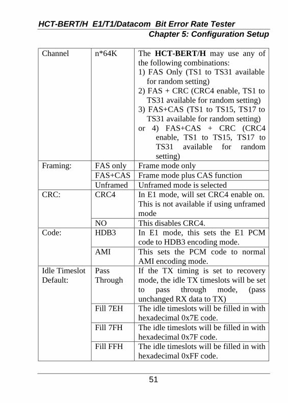
Channel n*64K The HCT-BERT/H may use any of
the following combinations: 1) FAS Only (TS1 to TS31 available
for random setting) 2) FAS + CRC (CRC4 enable, TS1 to
TS31 available for random setting) 3) FAS+CAS (TS1 to TS15, TS17 to
TS31 available for random setting) or 4) FAS+CAS + CRC (CRC4
enable, TS1 to TS15, TS17 to TS31 available for random setting)
Framing: FAS only Frame mode only FAS+CAS Frame mode plus CAS function Unframed Unframed mode is selected CRC: CRC4 In E1 mode, will set CRC4 enable on.
This is not available if using unframed mode
NO This disables CRC4. Code: HDB3 In E1 mode, this sets the E1 PCM
code to HDB3 encoding mode. AMI This sets the PCM code to normal
AMI encoding mode. Idle Timeslot Default:
Pass Through
If the TX timing is set to recovery mode, the idle TX timeslots will be set to pass through mode, (pass unchanged RX data to TX)
Fill 7EH The idle timeslots will be filled in with hexadecimal 0x7E code.
Fill 7FH The idle timeslots will be filled in with hexadecimal 0x7F code.
Fill FFH The idle timeslots will be filled in with hexadecimal 0xFF code.

HCT-BERT/H E1/T1/Datacom Bit Error Rate Tester Chapter 5: Configuration Setup
52
E-bit: Automatic E-bit is used to indicate a CRC-4
error. Both E-bits are set to 1 in normal mode. When a CRC-4 error is detected, one of the E-bits is set to 0.
Manual[11] Both of the E-bit positions of multiframe are set to 1
Manual[10] Manually transmits 1 in E-bit position of frame 13; manually transmits 0 in E-bit position of frame 15.
Manual[01] Manually transmits 0 in E-bit position of frame 13; manually transmits 1 in E-bit position of frame 15.
Manual[00] Both of the E-bit positions of a multiframe are set to 0.
Line Interface:
TERM 75 Sets HCT-BERT/H to E1 75 ohm terminal mode on TX and RX port.
TERM 120 Sets HCT-BERT/H to E1 120 ohm terminal mode on TX and RX port.
Bridge 75 Sets HCT-BERT/H to bridge mode on RX port (>1K ohm) and E1 75 ohm mode on TX port.
Bridge 120 Sets HCT-BERT/H to bridge mode on RX port (>1K ohm) and E1 120 ohm mode on TX port.
DSXMON 75
Sets HCT-BERT/H to E1 75 ohm DSX-MONitor mode on RX port.
DSXMON 120
Sets HCT-BERT/H to E1 120 ohm DSX-MONitor mode on RX port.
LBO: 0 dB TX Line Build Out is set to 0 dB -7.5dB TX Line Build Out is set to -7.5 dB -15dB TX Line Build Out is set to -15 dB -22.5dB TX Line Build Out is set to -22.5 dB

HCT-BERT/H E1/T1/Datacom Bit Error Rate Tester Chapter 5: Configuration Setup
53
Tx Timing: Internal Clock source from HCT-BERT/H
internal oscillator, 2.048MHz on E1 (E1 TX PCM clock source)
Recovery Clock source from E1 RX port recovered clock
Data Port Clock source is from the Data port's RX timing
External Clock source from Ext/Ref clock input jack
+50 ppm Clock source is from HCT-BERT/H internal oscillator, 2048K bps, with +50 ppm offset
-50 ppm Clock source is from HCT-BERT/H internal oscillator, 2048K bps, with −50 ppm offset

HCT-BERT/H E1/T1/Datacom Bit Error Rate Tester Chapter 5: Configuration Setup
54
Pattern: 63 Pseudo random pattern: 2e6-1
127 Pseudo random pattern: 2e7-1 511 Pseudo random pattern: 2e9-1 (O.153) 2047 Pseudo random pattern: 2e11-1
(O.152 AND O.153) 2e15-1 standard Pseudo random pattern: 2e15-1 (O.151)
(HCT-BERT/H will transmit and analyze this pattern into
2e15-1 non-standard
Pseudo random pattern: 2e15-1 (O.151 inverted)
E1/T1 frame.)
2e20-1 standard Pseudo random pattern: 2e20-1 (O.153)
2e20-1 non-standard
Pseudo random pattern: 2e20-1 (inverted)
QRSS Pseudo random pattern: 2e20-1 (O.151 QRSS)
2e23-1 standard Pseudo random pattern: 2e23-1 (O.151) 2e23-1 non-
standard Pseudo random pattern: 2e23-1 (O.151 inverted)
All One Repetitive pattern: all ones (11111...) All Zero Repetitive pattern: all zeros (00000...) ALT(0101) Repetitive pattern: alternating ones and
zeros (10101010...) 3 in 24 Repetitive pattern: 3 in 24 1 in 16 Repetitive pattern: 1 in 16 1 in 8 Repetitive pattern: 1 in 8 1 in 4 Repetitive pattern: 1 in 4 User Prog User programmable repetitive pattern.
The length of this pattern may be set from 1 to 32 bits. Please refer to Chapter 11 for details.
LIVE Will not care about the received pattern, which may be a real live signal or data. In this mode, the transmitting pattern will be set to Pseudo random pattern: 2e23-1.

HCT-BERT/H E1/T1/Datacom Bit Error Rate Tester Chapter 5: Configuration Setup
55
Error Type: Logic Force TX error type: Logic bit Frame Force TX error type: Framing bit CRC Force TX error type: CRC4 BPV Force TX error type: BPV Ins Error Rate:
Single Will force a single error when you press the Force Error Key.
1e-3 Will force errors continuously at transmit rate of 1e-3.
1e-4 Will force errors continuously at transmit rate of 1e-4.
1e-5 Will force errors continuously at transmit rate of 1e-5.
1e-6 Will force errors continuously at transmit rate of 1e-6.
1e-7 Will force errors continuously at transmit rate of 1e-7.
Test Period: Continuous The BERT test will run forever 1 Minute BERT will run for one minute. 15 Minutes BERT will run for fifteen minutes. 30 Minutes BERT will run for half an hour. 1 Hour BERT will run for an hour. 24 Hours BERT will run for one day. Display Type:
Brief Upon entering BERT function, the screen will show in "brief" mode.
Logical Upon entering BERT function, the screen will show in "logic" mode.
Frame Upon entering BERT function, the screen will show in "frame" mode.
CRC Upon entering BERT function, the screen will show in "CRC" mode.
BPV Upon entering BERT function, the screen will show in "BPV" mode.

HCT-BERT/H E1/T1/Datacom Bit Error Rate Tester Chapter 5: Configuration Setup
56
Histogram Upon entering BERT function, the
screen will show in "Histogram" mode.
M.2100 Upon entering BERT function, the screen will display in "M.2100" mode.
Print Interval:
Disable The printer will not print out results automatically.
5 Min The printer will print out test results every five minutes.
10 Min The printer will print out test results every ten minutes.
15 Min The printer will print out test results every fifteen minutes.
30 Min The printer will print out test results every half an hour
60 Min The printer will print out test results every hour.
Print On Error:
Disable The printer will not print out current test results while errors are received
Enable The printer will print out current test results while errors are received.
Beep Mode: Disable The unit will not issue audible "beeps" while errors are received.
Enable The unit will issue audible "beeps" while errors are received.
Off The histogram feature is disable. 1 Min The histogram storage duration is set
to 1 minute. 2 Min The histogram storage duration is set
to 2 minutes.
Histogram Storage Duration
30 Min The histogram storage duration is set to 30 minutes.

HCT-BERT/H E1/T1/Datacom Bit Error Rate Tester Chapter 5: Configuration Setup
57
T1(DS1) mode setting: Setting Parameter Description Config.: T1(DS1) HCT-BERT/H is configured to T1
mode Channel Full The HCT-BERT/H may be used any
of the following combinations : 1) ESF (F-bit, and TS1 to TS 24 are
used) 2) ESF + CRC (F-bit, CRC6 enable,
and TS1 to TS24 are used) 3) D4(SF) (F-bit, and TS1 to TS24 are
used) 4) SLC-96 (F-bit, and TS1 to TS24 are
used) 5) T1DM (F-bit, TS1 to TS23, and
T1DM Sync byte are used) 6) Unframed mode (whole frame is
used)

HCT-BERT/H E1/T1/Datacom Bit Error Rate Tester Chapter 5: Configuration Setup
58
Channel n*64K The HCT-BERT/H may use any of
the following combinations: 1) ESF (Random Timeslot setting
available) 2) ESF + CRC (CRC6 enable, random
Timeslot setting available) 3) D4(SF) (Random Timeslot setting
available) 4) SLC-96 (Random Timeslot setting
available) 5) T1DM (Random Timeslot setting)
n*56K The HCT-BERT/H may use any of the following combinations: 1) ESF (Random Timeslot setting
available + AB or ABCD Signaling)
2) ESF + CRC (CRC6 enable, random Timeslot setting available + AB or ABCD Signaling)
3) D4(SF) (Random Timeslot setting available + AB Signaling)
4) SLC-96 (Random Timeslot setting available + AB Signaling)
5) T1DM (Random Timeslot setting available + AB Signaling)
Framing: ESF ESF frame mode D4(SF) D4 frame mode SLC-96 SLC-96 frame mode T1DM T1DM frame mode Unframed Unframed mode is selected CRC: CRC6 In T1 mode, this enables CRC6. This
is not available if using D4, SLC-96, T1DM, or unframed mode.
NO This disables CRC6.

HCT-BERT/H E1/T1/Datacom Bit Error Rate Tester Chapter 5: Configuration Setup
59
Code: B8ZS In T1 mode, this sets the T1 PCM
code to B8ZS encoding mode. AMI This sets the PCM code to normal
AMI encoding mode. Idle Timeslot Default:
Pass Through
If the TX timing is set to recovery mode, the idle TX timeslots will be set to pass through mode, (unchanged RX data to TX pass through)
Fill 7EH The idle timeslots will be filled with hexadecimal 0x7E code.
Fill 7FH The idle timeslots will be filled with hexadecimal 0x7F code.
Fill FFH The idle timeslots will be filled with hexadecimal 0xFF code.
Performance Report
No
Reserved
Line Interface:
TERM 100
Sets HCT-BERT/H to T1 100 ohm terminal mode on TX and RX port.
Bridge Sets HCT-BERT/H to bridge mode on RX port (>1K ohm) and T1 100 ohm mode on TX port.
DSXMON 100
Sets HCT-BERT/H to T1 100 ohm DSX-MONitor mode on RX port.
LBO: 0 dB TX Line Build Out is set to 0 dB -7.5dB TX Line Build Out is set to -7.5 dB -15dB TX Line Build Out is set to -15 dB -22.5dB TX Line Build Out is set to -22.5 dB 0-133 Ft TX Line Build Out is set to 0-133 Ft 133-266 Ft TX Line Build Out is set to 133-266 Ft 266-399 Ft TX Line Build Out is set to 266-399 Ft 399-533 Ft TX Line Build Out is set to 399-533 Ft 533-655 Ft TX Line Build Out is set to 533-655 Ft

HCT-BERT/H E1/T1/Datacom Bit Error Rate Tester Chapter 5: Configuration Setup
60
Internal Clock source is from HCT-BERT/H
internal oscillator, 1.544MHz. Tx Timing: (E1/T1 TX PCM clock source)
Recovery Clock source is from T1 RX port recovered clock
Data Port Clock source is from the Data port's RX timing
External Clock source is from Ext/Ref clock input jack
+50 ppm Clock source is from HCT-BERT/H internal oscillator, 1.544MHz, with +50 ppm offset
-50 ppm Clock source is from HCT-BERT/H internal oscillator, 1.544MHz, with -50 ppm offset

HCT-BERT/H E1/T1/Datacom Bit Error Rate Tester Chapter 5: Configuration Setup
61
63 Pseudo random pattern: 2e6-1 127 Pseudo random pattern: 2e7-1 511 Pseudo random pattern: 2e9-1 (O.153)
Pattern: (HCT-BERT/H will transmit and analyze
2047 Pseudo random pattern: 2e11-1 (O.152 AND O.153)
2e15-1 standard Pseudo random pattern: 2e15-1 (O.151) 2e15-1 non-standard
Pseudo random pattern: 2e15-1 (O.151 inverted)
this pattern onto E1/T1 frame.) 2e20-1 standard Pseudo random pattern: 2e20-1 (O.153) 2e20-1 non-
standard Pseudo random pattern: 2e20-1 (inverted)
QRSS Pseudo random pattern: 2e20-1 (O.151 QRSS)
2e23-1 standard Pseudo random pattern: 2e23-1 (O.151) 2e23-1 non-
standard Pseudo random pattern: 2e23-1 (O.151 inverted)
All One Repetitive pattern: all ones (11111...) All Zero Repetitive pattern: all zeros (00000...) ALT(0101) Repetitive pattern: alternating ones and
zeros (10101010...) 3 in 24 Repetitive pattern: 3 in 24 1 in 16 Repetitive pattern: 1 in 16 1 in 8 Repetitive pattern: 1 in 8 1 in 4 Repetitive pattern: 1 in 4 User Prog User programmable repetitive pattern.
The length of this pattern may be set from 1 to 32 bits. Please refer to Chapter 11 for details.
LIVE Will not care about the received pattern, which may be a real live signal or data. In this mode, the transmitting pattern will be set to Pseudo random pattern: 2e23-1.

HCT-BERT/H E1/T1/Datacom Bit Error Rate Tester Chapter 5: Configuration Setup
62
Error Type: Logic Force TX error type: Logic bit Frame Force TX error type: Framing bit CRC Force TX error type: CRC4 BPV Force TX error type: BPV Ins Error Rate:
Single Will force a single error when you press the Force Error Key.
1e-3 Will force errors continuously at transmit rate of 1e-3.
1e-4 Will force errors continuously at transmit rate of 1e-4.
1e-5 Will force errors continuously at transmit rate of 1e-5.
1e-6 Will force errors continuously at transmit rate of 1e-6.
1e-7 Will force errors continuously at transmit rate of 1e-7.
Test Period: Continuous The BERT test will run forever 1 Minute BERT will run for one minute. 15 Minutes BERT will run for fifteen minutes. 30 Minutes BERT will run for half an hour. 1 Hour BERT will run for an hour. 24 Hours BERT will run for one day. Display Type:
Brief Upon entering BERT function, the screen will show in "brief" mode.
Logical Upon entering BERT function, the screen will show in "logic" mode.
Frame Upon entering BERT function, the screen will show in "frame" mode.
CRC Upon entering BERT function, the screen will show in "CRC" mode.
BPV Upon entering BERT function, the screen will show in "BPV" mode.

HCT-BERT/H E1/T1/Datacom Bit Error Rate Tester Chapter 5: Configuration Setup
63
Histogram Upon entering BERT function, the
screen will show in "Histogram" mode.
M.2100 Upon entering BERT function, the screen will show in "M.2100" mode.
Print Interval: Disable The printer will not print out results automatically.
5 Min The printer will print out test results every five minutes.
10 Min The printer will print out test results every ten minutes.
15 Min The printer will print out test results every fifteen minutes.
30 Min The printer will print out test results every half an hour
60 Min The printer will print out test results every hour.
Print On Error:
Disable The printer will not print out current test results while errors are received
Enable The printer will print out current test results while errors are received.
Off The histogram feature is disable. 1 Min The histogram storage duration is set
to 1 minutes. 2 Min The histogram storage duration is set
to 2 minutes.
Histogram Storage Duration
30 Min The histogram storage duration is set to 30 minutes.
Any changes made in any of the configuration menus do not have an immediate effect. By either leaving the configuration menu via the "ESC" key, or running BERT directly, the HCT-BERT/H will undergo a system re-initialization. Only then will the new configuration settings take effect.

HCT-BERT/H E1/T1/Datacom Bit Error Rate Tester Chapter 5: Configuration Setup
64
When you press the RUN key while in configuration setup, the HCT-BERT/H will re-initialize and run the BERT analysis function. Please refer to Chapter 6 for more information on the BERT analysis function. 5.3 Auto-Configuration The auto-configuration function may be used rather than the manual configuration. Under auto-configuration, the HCT-BERT/H will attempt to self configure by analyzing the live line connection. If the previous setting of the HCT-BERT/H was E1 mode, it will check and try all possible combinations of E1 framing, channel mode, coding, and patterns. If a match is not found, the HCT-BERT/H will check and try any and all possible combinations of T1 framing, channel mode, coding, and patterns.
To initiate the auto-configuration function, from the Manual Configuration selection menu, press the F1 key. The HCT-BERT/H will directly enter and execute the auto-configure function. While testing for a match, the HCT-BERT/H will show a "Testing…." message. When a configuration match is found, the HCT-BERT/H will display a "Test complete!" message. If the HCT-BERT/H cannot detect the current configuration, it will show a "No match!" message. The test result will be displayed similar to the following:
Auto configuration Frame Mode : FAS+CAS Channel : Full Code : HDB3 CRC : CRC4 Pattern : QRSS Test complete! <Press any key to continue.>
Auto-configuration Screen
HCT-BERT/H E1/T1/Datacom Bit Error Rate Tester Chapter 6: BERT Analysis
65
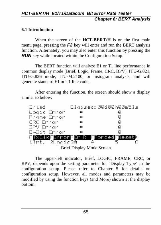
6.1 Introduction When the screen of the HCT-BERT/H is on the first main menu page, pressing the F2 key will enter and run the BERT analysis function. Alternately, you may also enter this function by pressing the RUN key while located within the Configuration Setup. The BERT function will analyze E1 or T1 line performance in common display mode (Brief, Logic, Frame, CRC, BPV), ITU-G.821, ITU-G.826 mode, ITU-M.2100, or histogram analysis, and will generate standard E1 or T1 line code. After entering the function, the screen should show a display similar to below:
Brief Elapsed:00d00h00m51s Logic Error = 0 Frame Error = 0 CRC Error = 0 BPV Error = 0 E-Bit Error = 0 FTxClkFErrorFEr R FForcedFResetM 1Int. 2Logic30 4 5 O
Brief Display Mode Screen The upper-left indicator, Brief, LOGIC, FRAME, CRC, or BPV, depends upon the setting parameter for "Display Type" in the configuration setup. Please refer to Chapter 5 for details on configuration setup. However, all modes and parameters may be modified by using the function keys (and More) shown at the display bottom.

HCT-BERT/H E1/T1/Datacom Bit Error Rate Tester Chapter 6: BERT Analysis
66
The top-right message, elapsed time, shows the duration of the current test. This analysis mode can be paused by pressing the RUN key, and continued again by pressing the RUN key. The bottom two lines show available function keys and their abbreviation. Pressing the MORE key will display additional function keys. By simply pressing the PgUp (page up) or PgDn (page down) keys, all of the display type screens can be viewed. Examples of all the other screens are shown in the following:
LOGIC Elapsed:00d00h00m51s Receive Count = 100602189 Errors = 0 Error Sec = 0 Error Free Sec = 51 Error Rate = 0.0e-00 FTxClkFErrorFEr R FForcedF M 1Int. 2Logic30 4 5 O
Logic Display Screen
LOGIC G.821 Elapsed:00d00h00m51s Available Sec. = 51 100% Degraded Min. = 0 % Severely ErrSec= 0 % Errored Second = 0 % Unavailable Sec= 0 % FTxClkFErrorFEr R FForcedF M 1Int. 2Logic30 4 5 O
Logic G.821 Display Screen
HCT-BERT/H E1/T1/Datacom Bit Error Rate Tester Chapter 6: BERT Analysis
67
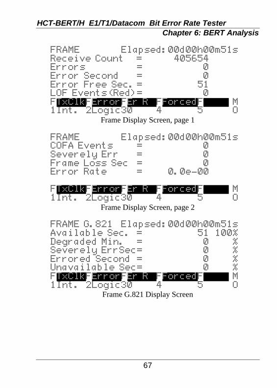
FRAME Elapsed:00d00h00m51s Receive Count = 405654 Errors = 0 Error Second = 0 Error Free Sec. = 51 LOF Events(Red)= 0 FTxClkFErrorFEr R FForcedF M 1Int. 2Logic30 4 5 O
Frame Display Screen, page 1
FRAME Elapsed:00d00h00m51s COFA Events = 0 Severely Err = 0 Frame Loss Sec = 0 Error Rate = 0.0e-00 FTxClkFErrorFEr R FForcedF M 1Int. 2Logic30 4 5 O
Frame Display Screen, page 2
FRAME G.821 Elapsed:00d00h00m51s Available Sec. = 51 100% Degraded Min. = 0 % Severely ErrSec= 0 % Errored Second = 0 % Unavailable Sec= 0 % FTxClkFErrorFEr R FForcedF M 1Int. 2Logic30 4 5 O
Frame G.821 Display Screen

HCT-BERT/H E1/T1/Datacom Bit Error Rate Tester Chapter 6: BERT Analysis
68
CRC Elapsed:00d00h00m51s Receive Count = 50706 Errors = 0 Error Sec = 0 Error Free Sec = 51 Error Rate = 0.0e-00 FTxClkFErrorFEr R FForcedF M 1Int. 2Logic30 4 5 O
CRC Display Screen
CRC G.821 Elapsed:00d00h00m51s Available Sec. = 51 100% Degraded Min. = 0 % Severely ErrSec= 0 % Errored Second = 0 % Unavailable Sec= 0 % FTxClkFErrorFEr R FForcedF M 1Int. 2Logic30 4 5 O
CRC G.821 Display Screen
BPV Elapsed:00d00h00m51s Receive Count = 100602189 Errors = 0 Error Sec = 0 Error Free Sec = 51 Error Rate = 0.0e-00 FTxClkFErrorFEr R FForcedF M 1Int. 2Logic30 4 5 O
BPV Display Screen

HCT-BERT/H E1/T1/Datacom Bit Error Rate Tester Chapter 6: BERT Analysis
69
BPV G.821 Elapsed:00d00h00m51s Available Sec. = 51 100% Degraded Min. = 0 % Severely ErrSec= 0 % Errored Second = 0 % Unavailable Sec= 0 % FTxClkFErrorFEr R FForcedF M 1Int. 2Logic30 4 5 O
BPV G.821 Display Screen
M21 in-serv.Elapsed:00d00h00m51s ES(RX)= 0|ES(TX)= 0 SES(RX) |SES(TX) = 0| = 0 Unavailable Sec(RX)= 0 Unavailable Sec(TX)= 0 FTxClkFErrorFEr R FForcedF M 1Int. 2Logic30 4 5 O
M.2100 Display Screen If you desire a hard copy print out of all the test results, connect the printer adapter cable from the printer port to a printer and press the PRINT key. You may also set testing duration, time interval to print results, or print when error occurs. All the configuration parameters may be set from the BERT display mode by using the function keys. Refer to section 6.4 Function Keys for an explanation of these keys and usage. For more information on setting these options and their meanings, please refer to Chapter 5 Configuration Setup.

HCT-BERT/H E1/T1/Datacom Bit Error Rate Tester Chapter 6: BERT Analysis
70
6.2 Performance The HCT-BERT/H displays the results of BERT testing for E1 or T1 on the LCD screen, while the LEDs provide instant display of status. This section depicts all of the on screen abbreviations and meanings. In "Brief" Format:
Logic Error : Received Error Logic Bit Counter Frame Error : Received Error Framing Bit Counter CRC Error : Received Error CRC Counter BPV Error : Received Error BPV(Bipolar Violation) Counter E-Bit Error : Received Error Far End Block(E-bit) Counter (applicable only in E1 mode) PatLos : Received Pattern Loss Status. SigLos : Received Signal Loss Status. FrmLos : Received Frame Loss Status.
In "Logic" Format:
Receive Count : Received Total Logic Bit Counter Errors : Received Error Logic Bit Counter Error Sec : Received Logic Bit Error Seconds Error Free Sec : Received Logic Bit Error Free Seconds Error Rate : Received Logic Error Rate (calculated of dividing received error logic bit counter by total received logic bit counter) PatLos : Received Pattern Loss Status.
In "Logic G.821" Format:
Available Sec. : Received G.821 Logic Bit Available Seconds Degraded Min. : Received G.821 Logic Bit Degraded Minutes

HCT-BERT/H E1/T1/Datacom Bit Error Rate Tester Chapter 6: BERT Analysis
71
Severely ErrSec : Received G.821 Logic Bit Severely Error Seconds Erred Second : Received G.821 Logic Bit Error Seconds Unavailable Sec : Received G.821 Logic Bit Unavailable Seconds
In "Logic G.826" Format:
Block : Received G.826 Logic Block Seconds Avl.Sec : Received G.826 Logic Block Available Second
Errored Blocks : Received G.826 Logic Error Block Counter(EB) Backgnd BlkErr : Received G.826 Logic Background Block Error (BBE) and Background Block Error Ratio (BBER)
Errored Second : Received G.826 Logic Seconds (ES) and Errored Second Ratio (ESR)
SeverelyErrSec : Received G.826 Logic Severely Errored Second (SES) and Severely Errored Second Ratio (SESR)
In "Frame" Format:
Receive Count : Received Total Frame Counter Errors : Received Error Framing Bit Counter Error Second : Received Framing Bit Error Seconds Error Free Sec. : Received Framing Bit Error Free Seconds LOF Events(Red): Received Loss of Frame Counter COFA Events : Received Change of Frame Alignment Counter Severely Err : Received Severely Error Frame Counter Frame Loss Sec. : Received Frame Loss Seconds Error Rate : Received Frame Error Rate (calculated by dividing the received error framing bit counter by the total received framing bit counter) SigLos : Received Signal Loss Status. FrmLos : Received Frame Loss Status.

HCT-BERT/H E1/T1/Datacom Bit Error Rate Tester Chapter 6: BERT Analysis
72
In "Frame G.821" Format:
Available Sec. : Received G.821 Frame Available Seconds Degraded Min. : Received G.821 Frame Degraded Minutes Severely ErrSec : Received G.821 Frame Severely Error Seconds Erred Second : Received G.821 Frame Erred Seconds Unavailable Sec : Received G.821 Frame Unavailable Seconds
In "CRC" Format:
Receive Count : Received Total CRC Counter Errors : Received Error CRC Counter Error Sec : Received CRC Error Seconds Error Free Sec : Received CRC Error Free Seconds Error Rate : Received CRC Error Rate (calculated of dividing received error CRC counter by total received CRC counter)
In "CRC G.821" Format:
Available Sec. : Received G.821 CRC Available Seconds Degraded Min. : Received G.821 CRC Degraded Minutes Severely ErrSec : Received G.821 CRC Severely Error Seconds Erred Second : Received G.821 CRC Error Seconds Unavailable Sec : Received G.821 CRC Unavailable Seconds
In "BPV" Format:
Receive Count : Received Total Logic Bit Counter Errors : Received Error BPV Counter Error Sec : Received BPV Error Seconds Error Free Sec : Received BPV Error Free Seconds Error Rate : Received BPV Error Rate (calculated by dividing received error BPV counter by the total received logic bit counter)

HCT-BERT/H E1/T1/Datacom Bit Error Rate Tester Chapter 6: BERT Analysis
73
In "BPV G.821" Format:
Available Sec. : Received G.821 BPV Available Seconds Degraded Min. : Received G.821 BPV Degraded Minutes Severely ErrSec : Received G.821 BPV Severely Error Seconds Erred Second : Received G.821 BPV Error Seconds Unavailable Sec : Received G.821 BPV Unavailable Seconds
In "M.2100" Format: In-service ES(RX) : Received Errored Seconds In-service ES(TX) : Transmitted Errored Seconds In-service SES(RX) : Received Severely Errored Seconds In-service SES(TX) : Transmitted Severely Errored Seconds In-service Unavailable Sec(RX): Received unavailable seconds In-service Unavailable Sec(TX): Transmit unavailable seconds Out-of-service ES : Errored seconds Out-of-service SES : Severely errored seconds Out-of-service US : Unavailable seconds

HCT-BERT/H E1/T1/Datacom Bit Error Rate Tester Chapter 6: BERT Analysis
74
6.3 Histogram By pressing PgUp(page up) or PgDn (page down) keys, the other Histogram analysis screens can be viewed. Examples of all the Histogram analysis screens are shown in the following:
SigLos
E.00d01h02m30s
FrmLos
Real2000-
02-
19
12:
35
PatLos
Cursor at
Power
2000-
02-
19
12:
35
Ex.Z
Alarms 0
10203040506
070809101112 01 Min/Bar
FLeft FRightFResouF F M 1 2 3 4 5 O
Alarms Histogram Display Screen (1)
1 Den
E.00d01h02m30s
AIS
Real2000-
02-
19
12:
35
SLIP
Cursor at
Yellow
2000-
02-
19
12:
35
RAI
Alarms 0
10203040506
070809101112 01 Min/Bar
FLef t F Rig htFR eso uF F M 1 2 3 4 5 O
Alarms Histogram Display Screen (2)
MRAI
E.00d01h02m30s
Error
Real2000-
02-
19
12:
35
Cursor at
2000-
02-
19
12:
35
Alarms 0
10203040506 0
70809101112 01 Min/Bar
FLef t F Rig htFR eso uF F M 1 2 3 4 5 O
Alarms Histogram Display Screen (3)

HCT-BERT/H E1/T1/Datacom Bit Error Rate Tester Chapter 6: BERT Analysis
75
1e8 -
1e7 - 1e6 -
1e5 - 1e4 -
1e3 - 1e2 -
1e1 -
E.00d01h02m30s Real2
000-
02-
19
12:
35
Cursor at 2000-
02-
19
12:
35
Logic Error
010203040506 0
70809101112 01 Min/Bar
FLef t FR i ght FRe sou F F M 1 2 3 4 5 O
Logic Error Histogram Display Screen
1e8 - 1e7 -
1e6 - 1e5 -
1e4 - 1e3 -
1e2 - 1e1 -
E.00d01h02m30s Real2
000-
02-
19
12:
35
Cursor at 2000-
02-
19
12:
35
Frame Error
010203040506 0
70809101112 01 Min/Bar
FLe ft FR igh tFR es ouF F M 1 2 3 4 5 O
Frame Error Histogram Display Screen
1e8 - 1e7 -
1e6 - 1e5 -
1e4 - 1e3 -
1e2 - 1e1 -
E.00d01h02m30s Real2
000-
02-
19
12:
35
Cursor at 2000-
02-
19
12:
35
CRC Error
010203040506 0
70809101112 01 Min/Bar
FLe ft FR igh tFR es ouF F M 1 2 3 4 5 O
CRC Error Histogram Display Screen

HCT-BERT/H E1/T1/Datacom Bit Error Rate Tester Chapter 6: BERT Analysis
76
1e8 -
1e7 - 1e6 -
1e5 - 1e4 -
1e3 - 1e2 -
1e1 -
E.00d01h02m30s Real2
000-
02-
19
12:
35
Cursor at 2000-
02-
19
12:
35
BPV Error
010203040506 0
70809101112 01 Min/Bar
FLe ft FR igh tFR es ouF F M 1 2 3 4 5 O
BPV Error Histogram Display Screen The "E.00d01h02m30s" shows the duration of the current test, in elapsed time. The "Real20
00-0
2-19 1
2:35" shows real time date and clock in year-month-day hour:minute format. The "Cursor at 20
00-0
2-19
12:35" shows cursor location. The above example has a flashing cursor
at location 01 position, and it indicates alarms or error counts status at storage time 2000/2/19 12:35. The "Alarms", "Logic Error", "Frame Error", "CRC Error", and "BPV error" indicates the current page is what kind of histogram analysis. The "30 Min/Bar" shows the resolution per bar of Histogram. If the Histogram Storage is set to off, the feature of Histogram analysis will not be available, and the Histogram screens will display the message "No Data".
If the Histogram storage time period is set to 1 minute, the display can show records for up to 3 days. If it is set to 2 minutes, the display can show records for up to 6 days. If it is set to 30 minutes, the display can show records for up to 90 days. By pressing "F1) Left", "F2) Right" function keys, or "ïï", "ðð" arrow keys on these screens will move the Histogram cursor to the left or right. The related storage time is shown on "Cursor at". It is useful for the customer to view the testing results in history.

HCT-BERT/H E1/T1/Datacom Bit Error Rate Tester Chapter 6: BERT Analysis
77
By pressing "F3) Resou (Resolution)" function key or "òò" arrow key the resolution of the Histogram analysis screen will change. The fine resolution is thirty minute per bar. It can be zoomed out to 6 hours per bar of resolution. The Alarms Histograms shows whether there are any Alarm errors in each period of storage time or not. If there were any alarm errors occurring in that period, the related position will get a small horizontal bar. The "History" LED will also flash, indicating an alarm has been stored in the Histogram.
The Logic, Frame, BPV, and CRC error Histogram show how many errors in each period of storage time. Zooming out the resolution will get the maximum errors count of this period of storage time. The display cannot zoom in the period of storage time. The Examine Analysis can review BERT normal, G.821, G.826, M.2100 testing results and Histogram. The file management function can store and recall normal BERT, G.821, and G.826 results but not the Histogram. Please refer to Chapter 2 HCT-BERT/H Overview, Receive Status, for more Alarms information. The following are the meanings of abbreviations on the Histogram screens: SigLos : Signal Loss Alarm FrmLos : Frame Loss Alarm PatLos : Pattern Loss Alarm Power : (reserve) Ex.Z : Excess Zero Alarm 1 Den : One Density Alarm
AIS : AIS Alarm SLIP : SLIP Alarm Yellow : Yellow Alarm RAI : RAI Alarm MRAI : MRAI Alarm Error : Logic, Frame, CRC, or BPV Errors Alarm

HCT-BERT/H E1/T1/Datacom Bit Error Rate Tester Chapter 6: BERT Analysis
78
6.4 Function Keys At the bottom of each display screen are two lines, with abbreviated and inverted character text indicating functions that may be applied in run mode. Under the abbreviated function is the current status. If you press any function key, the HCT-BERT/H will take some action immediately, such as changing the E1/T1 line status, framing mode, or forcing errors. The current status will be modified if it has several selected statuses. The function keys are in four different groups or sets of keys. Press the MORE key repeatedly to display the other function key groups. For example:
FTxClkFErrorFEr R FForcedFResetM 1Int. 2Logic30 4 5 O
Press MORE
FDisp.FFrameFCRC FCode FRModeM 1Brief2FAS 3CRC4 4HDB3 5T 75 O
Press MORE
FLBO FPattnFDurn.FReSyn FStoreM 10 2QRSS 3Cont.4 5 O
Press MORE
FLeft FrightFResou F F M 1 2 3 4 5 O

HCT-BERT/H E1/T1/Datacom Bit Error Rate Tester Chapter 6: BERT Analysis
79
Group 1 [F1]TxClk Transmit Clock Source Internal Change to internal clock source, initialize and restart test. Recover Change to RX recovery clock source, initialize and restart
test. DataPort Change to Data port RX clock source, initialize and restart
test. Ext. Change to external clock source, initialize and restart test. +50 Change to internal clock plus 50 ppm offset as clock
source, initialize and restart test. -50 Change to internal clock minus 50 ppm offset as clock
source, initialize and restart test. [F2]Error Forced Error Type Logic Change forced error type to logic. Frame Change forced error type to frame. CRC Change forced error type to CRC. BPV Change forced error type to BPV. [F3]Er R Automatic Forced Error Rate 0 Disable automatic forced errors action. 1e-3 Automatic forced error rate is set at a rate of 1e-3. 1e-4 Automatic forced error rate is set at a rate of 1e-4. 1e-5 Automatic forced error rate is set at a rate of 1e-5. 1e-6 Automatic forced error rate is set at a rate of 1e-6. 1e-7 Automatic forced error rate is set at a rate of 1e-7. [F4]Force Force a Single Error Insert a single error immediately. [F5]Reset Reset all test results and clear all of the received
counters and timers.

HCT-BERT/H E1/T1/Datacom Bit Error Rate Tester Chapter 6: BERT Analysis
80
Group 2 (after pressing the MORE key) [F1]Disp. Display Format Brief Changes the display format to brief display mode. Logic Changes the display format to logic display mode. Frame Changes the display format to frame display mode. CRC Changes the display format to CRC display mode. BPV Changes the display format to BPV display mode. [F2]Frame Frame Type FAS Changes the frame type to E1 FAS only mode. (E1 only) F+CAS Changes the frame type to E1 FAS and CAS enabled mode.
(E1 only) Unfr. Changes the frame type to unframed mode. ESF Changes the frame type to T1 ESF mode. (T1 only) D4 Changes the frame type to T1 D4(SF) mode. (T1 only) SLC96 Changes the frame type to T1 SLC-96 mode. (T1 only) T1DM Changes the frame type to T1 T1DM mode. (T1 only) [F3]CRC CRC Enable/Disable CRC4 Changes the E1 CRC to CRC4 enabled mode. (E1 only) NO Disables the CRC feature. CRC6 Changes the T1 CRC to CRC6 enabled mode. (T1 only) [F4]Code Code Format HDB3 Changes to HDB3 coding mode. (E1 only) AMI Changes to AMI coding mode. B8ZS Changes to B8ZS coding mode. (T1 only) [F5]Rmode Receive Mode T 75 Change to 75 ohm terminal mode. (E1 only) T 100 Change to 100 ohm terminal mode. (T1 only) T 120 Change to 120 ohm terminal mode. (E1 only)

HCT-BERT/H E1/T1/Datacom Bit Error Rate Tester Chapter 6: BERT Analysis
81
B 75 Change to Rx bridge mode, and Tx connects to 75 ohm
terminal mode. (E1 only) Bridg Change to Rx bridge mode, and Tx connects to 100 ohm
terminal mode. (T1 only) B 120 Change to Rx bridge mode, and Tx connects to 120 ohm
terminal mode. (E1 only) M 75 Change to DSX-MONitor 75 ohm mode.(E1 only) M 100 Change to DSX-MONitor 100 ohm mode.(T1 only) M 120 Change to DSX-MONitor 120 ohm mode.(E1 only) Group 3 (after pressing the MORE key again) [F1]LBO Line Build Out Attenuation 0 dB Change E1 LBO to 0 dB -7.5 Change E1 LBO to -7.5dB -15 Change E1 LBO to -15dB -22.5 Change E1 LBO to -22.5dB 0 F Change T1 LBO to 0 Feet 133F Change T1 LBO to 133 Feet 266F Change T1 LBO to 266 Feet 399F Change T1 LBO to 399 Feet 533F Change T1 LBO to 599 Feet 0 dB Change T1 LBO to 0 dB -7.5 Change T1 LBO to -7.5dB -15 Change T1 LBO to -15dB -22.5 Change T1 LBO to -22.5dB [F2]Pattn Pattern 63 63 127 127 511 511(O.153) 2047 2047(O.152 AND O.153) 2e15s 2e15-1(O.151) 2e15n 2e15-1(O.151 inverted)

HCT-BERT/H E1/T1/Datacom Bit Error Rate Tester Chapter 6: BERT Analysis
82
2e20s 2e20-1(O.153) 2e20n 2e20-1(inverted) QRSS QRSS(O.151 QRSS) 2e23s 2e23-1(O.151) 2e23n 2e23-1(O.151 inverted) All 1 All Ones All 0 All Zeros 0101 Alternate(0101) 3in24 3 in 24 1in16 1 in 16 1 in8 1 in 8 1 in4 1 in 4 UserP User Prog.# 1~3 LIVE Live signal or data [F3]Durn. Test Duration Cont. Continuous 1 Min 1 Minute 15Min 15 Minutes 30Min 30 Minutes 60Min 1 Hour 24Hrs 24 Hours [F4]ReSyn Re-sync framing [F5]Store Histogram storage duration Off Histogram feature is disabled. 1 Min The duration of Histogram storage is set to 1 minute. 2 Min The duration of Histogram storage is set to 2 minute. 30 Min The duration of Histogram storage is set to 30 minute.

HCT-BERT/H E1/T1/Datacom Bit Error Rate Tester Chapter 6: BERT Analysis
83
Group 4 (after pressing the MORE key again) [F1]Left Moves the Histogram cursor to the left position. [F1]Right Moves the Histogram cursor to the right position. [F1]Resou Changes the resolution of Histogram. 1 Min The resolution of Histogram display is set to 1 minute. 2 Min The resolution of Histogram display is set to 2 minutes. 30 Min The resolution of Histogram display is set to 30 minutes. 6 Hour The resolution of Histogram display is set to 6 hours. Other keys that have functions while running BERT:
SPACE Insert single error on BERT Analysis function.
BACK Turn backlight on or off on BERT Analysis function.
C Clears the history LED error status and returns LED status to real-time display. Any new error status will be stored into the history buffer and the History LED will flash.
F Freezes the current LED status when you press the F key. The Freeze LED will immediately light. To release the frozen LED status, press the F key again. The HCT-BERT/H will again show real-time LED status without clearing the history of LED error status, any error status in history will flash the History LED, and the Freeze LED will turn off again.

HCT-BERT/H E1/T1/Datacom Bit Error Rate Tester Chapter 6: BERT Analysis
84
?
Shows the history LED error status. The History LED will turn on solid, indicating that the current state of history is under review.
ïï ðð Move the Histogram cursor to the LEFT or RIGHT.
òò Changes the resolution of Histogram.

HCT-BERT/H E1/T1/Datacom Bit Error Rate Tester Chapter 7: Alarms and Looping
85
7.1 Alarms and Loopback To enter the "Alarm Setting" or "Loopback Setting" function, press the F3 key from the first menu page. There is no Loopback Setting when the HCT-BERT/H is set to E1 mode. Therefore, the HCT-BERT/H will go directly to the "Alarm Setting" screen. When the HCT-BERT/H is set to T1 mode, there is a sub-menu. The user may select between "Alarm Setting" or "Loopback Setting" as in the following display screen:
F1 :Alarm Setting F2 :Loopback Setting
Press the F1 key to enter the "Alarm Setting" function, or press the F2 key to enter the "Loopback Setting" function. 7.2 Alarm Setting Upon entering the "Alarm Setting" function, you will see a screen similar to the following:
Alarm Generate:[AIS ] Mode:[Off ] FAIS FYEL. FSIG. F F . 1 2(RAI) 3LOSS 4 5 .
Alarms Setting Screen for T1(cursor in "Alarm Generate" field)

HCT-BERT/H E1/T1/Datacom Bit Error Rate Tester Chapter 7: Alarms and Looping
86
Alarm Generate:[AIS ] Mode:[Off ] FAIS FREMOT FMULTIFSIG. F . 1 2 3REMOT4LOSS 5 .
Alarms Setting Screen for E1(cursor in "Alarm Generate" field) In T1 mode, the HCT-BERT/H can generate AIS (Alarm Indication Signal), Yellow Alarm (RAI), or SIGNAL LOSS manually. You may move the cursor up or down between the two entry fields by pressing the up or down arrow keys. You may select the type of alarm, which you require, simply by pressing the appropriate function key directly: [F1]AIS Alarm Indication Signal (unframed all ones) [F2]YEL.(RAI) Yellow Alarm (Remote Alarm Indicator) [F3]SIG.LOSS Signal Loss Alarm While in E1 mode, the HCT-BERT/H can generate AIS (Alarm Indication Signal), RAI (Remote Alarm Indication), MRAI (Multi-Remote Alarm Indication), or SIGNAL LOSS manually or automatically. You may move the cursor up or down between the two entry fields by pressing the up or down arrow keys. When the cursor is located in the "Alarm Generation" field, you may select the type of alarm, which you require, simply by pressing the appropriate function key directly: [F1]AIS Alarm Indication Signal (unframed all ones) [F2]REMOT RAI (Remote Alarm Indicator) [F3]MULTI REMOT MRAI (Multi Remote Alarm Indicator) [F4]SIG.LOSS Signal Loss Alarm

HCT-BERT/H E1/T1/Datacom Bit Error Rate Tester Chapter 7: Alarms and Looping
87
Pressing the down arrow key will move the cursor to the "Mode" field, a second set of function keys are then active. Refer to the screen display below:
Alarm Generate:[AIS ] Mode:[OFF ] FOFF FON FAUTO F F . 1 2 3 4 5 .
Alarm Setting Screen (cursor in "Mode" field) You may then select whether alarm generation is on, off, or auto simply by pressing the function key directly: [F1]Off alarm generation disable [F2]On generate alarm manually [F3]AUTO automatic alarm generation (E1 mode only) AIS (Alarm Indication Signal): When activated, the HCT-BERT/H replaces all data output on
the TX port with an unframed all ones signal (AIS). Yellow Alarm (Remote Alarm): In T1 mode: SF(D4) Bit 2 of every timeslot set to 0.
ESF By configuration DL1 to continuously transmit an all 0 BOP priority codeword.
SLC96 Bit 2 of every timeslot set to 0. T1DM Y bit of the sync byte (24th byte) set to 0.
RAI (Remote Alarm Indicator): In E1 mode, the "A" bit in timeslot 0 is set to 1.
MRAI (Multi Remote Alarm Indicator): In E1 mode, the "Y" bit in timeslot 16 is set to 1.

HCT-BERT/H E1/T1/Datacom Bit Error Rate Tester Chapter 7: Alarms and Looping
88
7.3 Loopback Setting NOTE: Loopback Setting is not applicable when in E1 mode. After entering the "Loopback Setting" function, you will first see a screen for a few seconds describing the loop up and loop down keys;
"-" loop down "/" loop up then you will see a screen similar to the ones below:
TYPE [IN-BAND] [LINE (CSU) ] LOOP UP 10000 LOOP DOWN 100 FRAMING [INSERTED ] AUTO RESPONSE [OFF ] TESTER PAYLOAD LOOPED [DOWN ] Fin- Fout- F F F . 1band 2band 3 4 5 .
Loopback Setting Screen (cursor in "In-band" field) Or:
TYPE [OUT-BAND][LINE (CSU) ] LOOP UP 00001110 11111111 LOOP DOWN 00111000 11111111 AUTO RESPONSE [OFF ] TESTER LINE LOOPED [DOWN ] TESTER PAYLOAD LOOPED [DOWN ] Fin- Fout- F F F . 1band 2band 3 4 5 .
Loopback Setting Screen (cursor in "Out-band" field)

HCT-BERT/H E1/T1/Datacom Bit Error Rate Tester Chapter 7: Alarms and Looping
89
The HCT-BERT/H can generate Loop Up Code or Loop
Down Code manually, detect and respond to them automatically. You may move the cursor up or down between the two entry fields by pressing the up or down arrow keys. When the cursor is located in the "Type" field, you may select the type of loopback, which you require, simply by pressing the appropriate function key directly: Only ESF has both In-Band and Out-Band loop codes, D4, SLC-96, and T1DM have only In-Band loop codes. Pressing the "/" key will force generating of loop up code, while pressing the "-" key will force generating of loop down code. The following are the specification of HCT-BERT/H Loopback Setting: 1) Loop Type : InBand, Out-Band 2) In-Band Loop Code Type : LINE (CSU), SmartJack (4), SmartJack (5), User Programmable 3) Out-Band Loop Code Type : LINE (CSU), Payload(CSU), SmartJack 4) In-Band Loop Code : LINE (CSU) Up: 10000 Down: 100 SmartJack (4) Up: 1100 Down: 1110 SmartJack (5) Up: 11000 Down: 11100
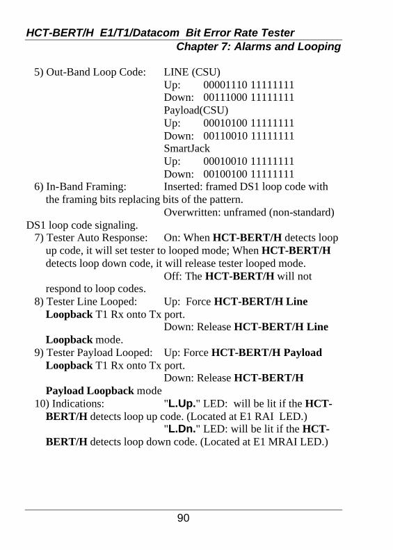
HCT-BERT/H E1/T1/Datacom Bit Error Rate Tester Chapter 7: Alarms and Looping
90
5) Out-Band Loop Code: LINE (CSU) Up: 00001110 11111111 Down: 00111000 11111111 Payload(CSU) Up: 00010100 11111111 Down: 00110010 11111111 SmartJack Up: 00010010 11111111 Down: 00100100 11111111 6) In-Band Framing: Inserted: framed DS1 loop code with
the framing bits replacing bits of the pattern. Overwritten: unframed (non-standard) DS1 loop code signaling. 7) Tester Auto Response: On: When HCT-BERT/H detects loop
up code, it will set tester to looped mode; When HCT-BERT/H detects loop down code, it will release tester looped mode.
Off: The HCT-BERT/H will not respond to loop codes.
8) Tester Line Looped: Up: Force HCT-BERT/H Line Loopback T1 Rx onto Tx port.
Down: Release HCT-BERT/H Line Loopback mode.
9) Tester Payload Looped: Up: Force HCT-BERT/H Payload Loopback T1 Rx onto Tx port.
Down: Release HCT-BERT/H Payload Loopback mode
10) Indications: "L.Up." LED: will be lit if the HCT-BERT/H detects loop up code. (Located at E1 RAI LED.)
"L.Dn." LED: will be lit if the HCT-BERT/H detects loop down code. (Located at E1 MRAI LED.)

HCT-BERT/H E1/T1/Datacom Bit Error Rate Tester Chapter 8: Signal Result
91
8.1 Signal Result The "Signal Result" function allows the user to verify the received E1/T1 PCM signal. The "Signal Result" function is entered by pressing the F1 key from the second menu page. When you enter this function, the E1/T1 RX port signal results will be displayed as follows:
---------Signal Result----------- RX Frequency : 01544001 Hz RX Freq. Offset : 0001 ppm EXT Frequency : -------- Hz EXT Freq. Offset : ------ Hz
Signal Result Screen display Rx Frequency: The current RX port signal frequency is shown, measured in Hertz. Rx Freq. Offset: The current RX port signal frequency is compared with the internal clock frequency, and shown with the offset in ppm. EXT Frequency: The current Ext/Ref port signal frequency is shown, measured in Hz. EXT Freq. Offset: The current Ext/Ref port signal frequency is compared with the Rx port signal frequency, and shown with the offset in Hz. Press the ESC key to exit this function.

HCT-BERT/H E1/T1/Datacom Bit Error Rate Tester Chapter 8: Signal Result
92
This page left blank intentionally.

HCT-BERT/H E1/T1/Datacom Bit Error Rate Tester Chapter 9: Signaling Setup
93
9.1 Signaling Setup In E1 mode, when you set the HCT-BERT/H to E1 CAS framing mode, signaling is enabled. To enter the signaling setup function, press the F2 key from the second menu set pages. If the HCT-BERT/H is not in CAS mode, it will not be able to enter this function. In T1 mode, when you set the HCT-BERT/H to T1 n*56K channel mode, signaling is enabled. Please refer to Chapter 5 for more information on Channel setting. To enter the signaling setup function, press the F2 key from the second menu set pages. If the HCT-BERT/H is not in n*56K channel mode, the signaling bits will not be correct. While in n*56K channel mode, the timeslots use 7 bits for data, the eighth bit can then be used for signaling. Since all 8 bits are used for data while in n*64K channel mode, there is no room for the signaling bit. Trying to display the bits in this mode will result in a garbage display. The ESF mode has A,B,C,D or A,B, signaling bit modes. In D4, SLC-96, and T1DM modes, there is only A, B signaling bits mode. After you enter this function, you will see a screen similar to that below:
TS [01] Tx ABCD BITS [1010] Rx ABCD BITS : 1010 FDec FInc FSel FSet FReset . 1TS 2TS 3Bit 4Bit 5Bit .
Signaling Setup Screen The screen shows which TX time slot is under setup, and its current ABCD bits. The flashing cursor is under the ABCD bit field, and can be moved to A, B, C, or D locations by pressing the right or left arrow keys, or by pressing the F3 Select Bit key.

HCT-BERT/H E1/T1/Datacom Bit Error Rate Tester Chapter 9: Signaling Setup
94
The Signaling Setup function key definitions are as follows: [F1] DecTS: Will decrement to the previous time slot selection. [F2] Inc TS: Will increment to the next time slot selection. [F3] Sel Bit: Will select one of the ABCD bits. [F4] Set Bit: Will set the selected ABCD bit to "one". [F5] Reset Bit: Will clear the selected ABCD bit to "zero". [Up Arrow] Select previous timeslot number. (same as F1) [Down Arrow] Select next timeslot number. (same as F2) [Left Arrow] Selects the next bit to the left. [Right Arrow] Selects the next bit to the left. (same as F3) To exit the "Signaling Setup" function, press the ESC key.

HCT-BERT/H E1/T1/Datacom Bit Error Rate Tester Chapter 10: Signaling Display
95
10.1 Signaling Display To enter the "Signaling Display" function, press the F3 key from the second menu set page. In E1 mode, after you enter this function, you will see a screen similar to that below:
MA:0000 08:0101 XY:1011 24:0101 01:0101 09:0101 17:0101 25:0101 02:0101 10:0101 18:0101 26:0101 03:0101 11:0101 19:0101 27:0101 04:0101 12:0101 20:0101 28:0101 05:0101 13:0101 21:0101 29:0101 06:0101 14:0101 22:0101 30:0101 07:0101 15:0101 23:0101 31:0101
E1 Signaling Display Screen The screen shows 32 RX time slot’s signaling A,B,C, and D bits. The actual location of the bits is in time slot 16 during E1 CAS framing mode. If the HCT-BERT/H is not in E1 CAS mode, it is not able to enter this function. The first time slot 16 of the first frame of multi-frame contains the multi-frame alignment and XYXX bits. They are shown in the MA and XY fields.

HCT-BERT/H E1/T1/Datacom Bit Error Rate Tester Chapter 10: Signaling Display
96
In T1 mode, after you enter this function, you will see a screen similar to that below:
01:0101 09:0101 17:0101 02:0101 10:0101 18:0101 03:0101 11:0101 19:0101 04:0101 12:0101 20:0101 05:0101 13:0101 21:0101 06:0101 14:0101 22:0101 07:0101 15:0101 23:0101 08:0101 16:0101 24:0101
T1 Signaling Display Screen The screen shows 24 RX time slot’s signaling A,B,C, and D bits. The actual location of the bits is in each bit 8 of each timeslot. If the HCT-BERT/H doesn’t receive n*56K mode data and signaling bits, the values may be shown randomly depending upon the T1 Rx data. For more information on channel setting, please refer to Chapter 5. To exit the "Signaling Display" function, press the ESC key.

HCT-BERT/H E1/T1/Datacom Bit Error Rate Tester Chapter 11: Remote Control
97
11.1 Introduction
The actual function of the REMOTE CONTROL utility is to provide the PC with a terminal emulation ability. This utility may be found on the accessory floppy diskette (or CDROM) and is designed to run in a pure DOS ™ mode only. The remote functions may also be run from a stand alone terminal or by using a different terminal emulation program on your PC such as a VT100™ emulator or Windows 9X™ HyperTerminal™, by Hilgraeve. The remote PC can control the HCT-BERT/H by direct connection or via dial-up MODEM as displayed in the following figures.
Figure 11-1 Direct Connection
Figure 11-2 Dial-up MODEM Connection
Direct connection is made between the PC’s communication port, COM1:, COM2:, COM3:, or COM4:, and the male DB9 Remote Control port connector on the HCT-BERT/H with the supplied Remote cable. As the HCT-BERT/H’s Remote Control Port is DCE, a null modem cable must be used when using a dial-up modem connection. (Refer to Appendix B for cable pinouts).

HCT-BERT/H E1/T1/Datacom Bit Error Rate Tester Chapter 11: Remote Control
98
When using REMOTE CONTROL or other terminal emulation program to connect to the HCT-BERT/H, the following functions of the HCT-BERT/H may be controlled remotely: 1. Configuration Setup. 2. BERT Test and Analysis. 3. Reset System. 4. Timeslot Setup 5. Signal Result 6. Loopback Setup 7. Signaling Setup 11.2 Remote Port Setup You can enter this setup menu by pressing the F4 key from main menu page 2. The screen will show a display similar to the following:
----- Remote Port Setup ------- Baud : 9600 Data Bits :[8 ] Parity :[None ]
Remote Port Setup Display Screen
Pressing the Right or Left Arrow keys will change the remote port baud rate. The available remote port baud rates are 300, 600, 1200, 2400, 4800, 9600, 19200, and 38400 bps. The data bits and parity are set to 8 and NONE respectively and cannot be changed.

HCT-BERT/H E1/T1/Datacom Bit Error Rate Tester Chapter 11: Remote Control
99
11.3 Operation
Operating the HCT-BERT/H remotely via the Remote Port simply involves connecting the HCT-BERT/H as shown in figure 11-1 or 11-2 and running a terminal emulation program on the remote PC. The remote PC must set its RTS (signal 105) and DTR (signal 108) to active (space, 0) and use the same baud rate, data bit, and parity settings to control the HCT-BERT/H. When powered on, the HCT-BERT/H will initialize and check for an active connection on its Remote Port. After the HCT-BERT/H initializes the Remote Port, pressing the space bar twice on the PC or the terminal will display the remote screen.
*HCT-BERT MAIN MENU* P1 1)CONFIG. SETUP 2)BERT ANALYSIS 3)RESET SYSTEM 4)ALARM 5)LOOPBACK SETUP 0)EXIT +:PGDN -:PGUP *SELECT 0-5
(Main Menu) Remote PC Display Screen #1
By pressing the "+" key the next menu page can be displayed. Pressing the "-" key will display the previous menu page. The HCT-BERT/H has three main menu pages. Page 2 and 3 are shown on the next page.

HCT-BERT/H E1/T1/Datacom Bit Error Rate Tester Chapter 11: Remote Control
100
*HCT-BERT MAIN MENU* P2 1)SIGNAL RESULT 2)SIGNALING SETUP 3)USER PROGRAM PATTERN 4)TIME SLOT SETUP 5)TIME SLOT MAP DATA 0)EXIT +:PGDN -:PGUP *SELECT 0-5
(Main Menu)
Remote PC Display Screen #2
*HCT-BERT MAIN MENU* P3 1)MISCELLANEOUS 2)CLOCK SETUP 3)LED STATUS 0)EXIT +:PGDN -:PGUP *SELECT 0-3
(Main Menu)
Remote PC Display Screen #3
To exit, press the zero key on PC. The HCT-BERT/H will
disable CTS/DSR and DTR, wait 2 seconds and then exit. If you are using a modem connection, the modem will automatically hang up when DTR drops.

HCT-BERT/H E1/T1/Datacom Bit Error Rate Tester Chapter 11: Remote Control
101
Pressing the "1" key, from the first main menu page, will enter the Configuration Setup function. Pressing the "2" key will enter the BERT Analysis function. Pressing the "3" key will enter the System Reset function, etc.
After entering a sub-function, you may type in any of the commands which are shown on the remote PC screen. The HCT-BERT/H will execute the appropriate action and send an "OK" message to the remote PC. If a command is incorrectly entered, the remote PC will receive the "ERROR COMMAND, TRY AGAIN!" message from the HCT-BERT/H. Pressing the "0" key will escape the current sub-function and return to the main menu. The following display is an example of the Configuration Setup sub-function. The commands all consist of two letters, one number key combinations. Please refer to 11.4.2 for a complete list of the Configuration Setup commands.
*CONFIG SETUP*' CF1,CF2,CH1~3,CO1,CO2,CR1,CR2, EB1~5,ET1~4,FM1~5,ID1~4,IE1~6, LB1~9,LI1~6,PA1~9,PAA~M,TT1~6,SE1~2 PE1~2,PI1~6,BM1~2,TP1~6 *COMMAND/0/SPACE?
(Configuration Setup) Remote PC Display Screen

HCT-BERT/H E1/T1/Datacom Bit Error Rate Tester Chapter 11: Remote Control
102
The following display is an example of the BERT Analysis sub-function. The commands all consist of two letters, one number key combinations. Please refer to 11.4.3 for a complete list of the BERT Analysis commands.
*BERT ANALYSIS* P1-2 CO1,CO2,CR1,CR2,ET1~4,FM1~5, FR1,IE1~6,LB1~4,LI1~6,PA1~9, PAA~M,RS1,RT1,SH1~9,TT1~6 TP1~6 *COMMAND/0/SPACE?
(BERT Analysis) Remote PC Display Screen
The following is the System Reset sub-function. Please refer to 11.4.4 for a complete list of the BERT Analysis commands.
*RESET SYSTEM* *YES/0/SPACE?
(Reset System) Remote PC Display Screen
The following display is an example of the Timeslot Setup sub-function. The commands all consist of four letters, timeslot setting command includes two number key combinations. Please refer to 11.4.5 for a complete list of the Timeslot Setup commands.
*TIMESLOT SETUP* SHOW,T01I~T31I,T01P~T31P, T01U~T31U *COMMAND/0/SPACE?
(Timeslot Setup) Remote PC Display Screen

HCT-BERT/H E1/T1/Datacom Bit Error Rate Tester Chapter 11: Remote Control
103
After entering the SHOW command, the HCT-BERT/H will send out a timeslot mapping message similar to the following:
T01~07: F * * * * * * * T08~15: * * * * * * * * T16~23: * * * * * * * * T24~31: * * * * * * * *
(Timeslot Setup Status) Remote PC Display Screen
The following display is an example of the Time Slot Map Data function.
*TIME SLOT MAP DATA* P2-5 FAS TS0:1B AA AA AA AA AA AA AA TS8:AA AA AA AA AA AA AA AA TS16:AA AA AA AA AA AA AA AA TS24:AA AA AA AA AA AA AA AA NFAS TS0:DF AA AA AA AA AA AA AA TS8:AA AA AA AA AA AA AA AA TS16:AA AA AA AA AA AA AA AA TS24:AA AA AA AA AA AA AA AA *SPACE=NEW TIME SLOT MAP DATA* *COMMAND/0/SPACE?
(Timeslot MAP Data)
Remote PC Display Screen

HCT-BERT/H E1/T1/Datacom Bit Error Rate Tester Chapter 11: Remote Control
104
The following display is an example of the Signal Result sub-function. It includes current setting status and testing result. Please refer to 11.4.7 for a complete list of the Signal Result commands.
*SIGNAL RESULT* RX Frequency : 02048005 Hz RX Freq. Offset : 0002 ppm EXT Frequency : -------- Hz EXT Freq. Offset: ------ Hz *SPACE=TESTING NEW RESULT* *0/SPACE
(Signal Result Status) Remote PC Display Screen
The following display is an example of the Signaling Bits
Setup sub-function. Please refer to 11.4.9 for a complete list of the Signaling Bits Setup commands. Whenever setting up the timeslot signaling bits, the screen will get the last modified timeslot signaling bits status.
*SIGNALING SETUP* --- TS [01] ABCD BITS [1010] --- COMMAND: T010001 ~ T311111 *COMMAND/0/SPACE?
(Signaling Bits Setup) Remote PC Display Screen

HCT-BERT/H E1/T1/Datacom Bit Error Rate Tester Chapter 11: Remote Control
105
The following display is an example of the LED Status sub-
function. It includes current setting status and testing result. Please refer to 11.4.12 for a complete list of the LED Status commands.
* LED Status (E1)* OK '?':History 'C':Clear History ** '0' to Exit **
(LED Status) Remote PC Display Screen
The following display is an examples of error messages showing on E1 received signal loss, frame loss, pattern loss, excess zero error, one density, AIS, SLIP, yellow alarm, RAI, MRAI, and other errors.
* LED Status (E1)* OK ** ‘0’ to exit ** * LED Status (E1)* Signal Loss ** ‘0’ to exit ** * LED Status (E1)* Pattern Loss/Error ** ‘0’ to exit **
(LED Status) Remote PC Display Screen

HCT-BERT/H E1/T1/Datacom Bit Error Rate Tester Chapter 11: Remote Control
106
11.4 Commands 11.4.1 Main Menu Setup Command List: <space> Shows the current page again. <0> Initializes MODEM, exits remote control function. <1> CONFIG. SETUP <2> BERT ANALYSIS <3> RESET SYSTEM <4> ALARM <5> LOOPBACK SETUP [page 2] <1> SIGNAL RESULT <2> SIGNALING SETUP <3> USER PROGRAM PATTERN <4> TIME SLOT SETUP <5> TIME SLOT MAP DATA [page 3] <1> MISCELLANEOUS <2> CLOCK SETUP <3> LED STATUS

HCT-BERT/H E1/T1/Datacom Bit Error Rate Tester Chapter 11: Remote Control
107
11.4.2 Configuration Setup Command List: <space> Shows current page again. <0> Escapes to main menu. <CF1> Sets to E1 configuration mode. <CF2> Sets to T1 configuration mode. (Configuration Setup Command list continued) <CH1> Sets to Full channel mode. <CH2> Sets to n*64K channel mode. <CH3> Sets to n*56K channel mode. (T1) <CO1> Sets code to HDB3 mode (E1) or B8ZS mode (T1). <CO2> Sets code to AMI mode. <CR1> Sets CRC enable. <CR2> Sets CRC disable. <EB1> Sets E-bit to Automatic mode. (E1) <EB2> Sets E-bit to Manual 11 mode. (E1) <EB3> Sets E-bit to Manual 10 mode. (E1) <EB4> Sets E-bit to Manual 01 mode. (E1) <EB5> Sets E-bit to Manual 00 mode. (E1) <ET1> Sets error type to Logic. <ET2> Sets error type to Frame. <ET3> Sets error type to CRC. <ET4> Sets error type to BPV. <FM1> Sets to FAS only mode (E1) or ESF mode (T1). <FM2> Sets to FAS+CAS mode (E1) or SF/D4 mode (T1). <FM3> Sets to Unframed mode (E1) or SLC96 mode (T1). <FM4> Sets to T1DM mode (T1). <FM5> Sets to Unframed mode (T1). <ID1> Sets default idle timeslot to Fill 7EH mode. <ID2> Sets default idle timeslot to Fill 7FH mode. <ID3> Sets default idle timeslot to Fill FFH mode. <ID4> Sets default idle timeslot to Pass Thru mode.

HCT-BERT/H E1/T1/Datacom Bit Error Rate Tester Chapter 11: Remote Control
108
(Configuration Setup Command list continued) <IE1> Sets insert error rate to Single. <IE2> Sets insert error rate to 1e-3. <IE3> Sets insert error rate to 1e-4. <IE4> Sets insert error rate to 1e-5. <IE5> Sets insert error rate to 1e-6. <IE6> Sets insert error rate to 1e-7. <LB1> Sets LBO to 0dB. <LB2> Sets LBO to -7.5dB. <LB3> Sets LBO to -15dB. <LB4> Sets LBO to -22.5dB. <LB5> Sets LBO to 0-133 Ft. (T1) <LB6> Sets LBO to 133-266 Ft. (T1) <LB7> Sets LBO to 266-399 Ft. (T1) <LB8> Sets LBO to 399-533 Ft. (T1) <LB9> Sets LBO to 533-655 Ft. (T1) <LI1> Sets line interface to terminal 75 ohm (E1) or terminal 100 ohm (T1). <LI2> Sets line interface to terminal 120 ohm (E1) or Bridge 100 ohm (T1). <LI3> Sets line interface to Bridge 75 ohm (E1) or Monitor 100 ohm (T1). <LI4> Sets line interface to Bridge 120 ohm (E1). <LI5> Sets line interface to Monitor 75 ohm (E1). <LI6> Sets line interface to Monitor 120 ohm (E1). <PA1> Sets pattern to 63. <PA2> Sets pattern to 127. <PA3> Sets pattern to 511. <PA4> Sets pattern to 2047. <PA5> Sets pattern to 2e15 standard. <PA6> Sets pattern to 2e15 non-standard. <PA7> Sets pattern to 2e20 standard. <PA8> Sets pattern to 2e20 non-standard.

HCT-BERT/H E1/T1/Datacom Bit Error Rate Tester Chapter 11: Remote Control
109
(Configuration Setup Command list continued) <PA9> Sets pattern to QRSS. <PAA> Sets pattern to 2e23 standard. <PAB> Sets pattern to 2e23 non-standard. <PAC> Sets pattern to All 1 (mask). <PAD> Sets pattern to All 0 (space). <PAE> Sets pattern to 0101 (alternate). <PAF> Sets pattern to 3 in 24. <PAG> Sets pattern to 1 in 16. <PAH> Sets pattern to 1 in 8. <PAI> Sets pattern to 1 in 4. <PAJ> Sets pattern to User Programmable #1. <PAK> Sets pattern to User Programmable #2. <PAL> Sets pattern to User Programmable #3. <PAM> Sets pattern to LIVE. <TT1> Sets Tx Timing to Internal mode. <TT2> Sets Tx Timing to Recovery mode. <TT3> Sets Tx Timing to External mode. <TT4> Sets Tx Timing to Data Port mode. <TT5> Set Tx Timing to +50ppm. <TT6> Set Tx Timing to -50ppm. <PE1> Set Print On Error to Disable. <PE2> Set Print On Error to Enable. <BM1> Set Beep Mode to Disable. <BM2> Set Beep Mode to Enable. <TP1> Set Test Period to Continuous. <TP2> Set Test Period to 1 minute. <TP3> Set Test Period to 15 minutes. <TP4> Set Test Period to 30 minutes. <TP5> Set Test Period to 1 hour. <TP6> Set Test Period to 24 hours.

HCT-BERT/H E1/T1/Datacom Bit Error Rate Tester Chapter 11: Remote Control
110
(Configuration Setup Command list continued) <PI1> Set Print Interval to Disable. <PI2> Set Print Interval to 5 minutes. <PI3> Set Print Interval to 10 minutes. <PI4> Set Print Interval to 15 minutes. <PI5> Set Print Interval to 30 minutes. <PI6> Set Print Interval to 60 minutes. <SE1> Set Sensitivity to High. <SE2> Set Sensitivity to Low. 11.4.3 BERT Analysis Command List: <Space> Shows current page again. <0> Escapes to main menu. <CO1> Sets code to HDB3 mode (E1) or B8ZS mode (T1). <CO2> Sets code to AMI mode. <CR1> Sets CRC enable. <CR2> Sets CRC disable. <ET1> Sets error type to Logic. <ET2> Sets error type to Frame. <ET3> Sets error type to CRC. <ET4> Sets error type to BPV. <FM1> Sets to FAS only mode (E1) or ESF mode (T1). <FM2> Sets to FAS+CAS mode (E1) or SF/D4 mode (T1). <FM3> Sets to Unframe mode (E1) or SLC96 mode (T1). <FM4> Sets to T1DM mode (T1). <FM5> Sets to Unframe mode (T1). <FR1> Force one error. <IE1> Sets insert error rate to Single. <IE2> Sets insert error rate to 1e-3. <IE3> Sets insert error rate to 1e-4. <IE4> Sets insert error rate to 1e-5. <IE5> Sets insert error rate to 1e-6.

HCT-BERT/H E1/T1/Datacom Bit Error Rate Tester Chapter 11: Remote Control
111
(BERT Analysis Command list continued) <IE6> Sets insert error rate to 1e-7. <LB1> Sets LBO to 0dB. <LB2> Sets LBO to -7.5dB. <LB3> Sets LBO to -15dB. <LB4> Sets LBO to -22.5dB. <LB5> Sets LBO to 0-133 Ft. (T1) <LB6> Sets LBO to 133-266 Ft. (T1) <LB7> Sets LBO to 266-399 Ft. (T1) <LB8> Sets LBO to 399-533 Ft. (T1) <LB9> Sets LBO to 533-655 Ft. (T1) <LI1> Sets line interface to terminal 75 ohm (E1) or terminal 100 ohm (T1). <LI2> Sets line interface to terminal 120 ohm (E1) or Bridge 100 ohm (T1). <LI3> Sets line interface to Bridge 75 ohm (E1) or Monitor 100 ohm (T1). <LI4> Sets line interface to Bridge 120 ohm (E1). <LI5> Sets line interface to Monitor 75 ohm (E1). <LI6> Sets line interface to Monitor 120 ohm (E1). <PA1> Sets pattern to 63. <PA2> Sets pattern to 127. <PA3> Sets pattern to 511. <PA4> Sets pattern to 2047. <PA5> Sets pattern to 2e15 standard. <PA6> Sets pattern to 2e15 non-standard. <PA7> Sets pattern to 2e20 standard. <PA8> Sets pattern to 2e20 non-standard. <PA9> Sets pattern to QRSS. <PAA> Sets pattern to 2e23 standard. <PAB> Sets pattern to 2e23 non-standard. <PAC> Sets pattern to All 1 (mask). <PAD> Sets pattern to All 0 (space).

HCT-BERT/H E1/T1/Datacom Bit Error Rate Tester Chapter 11: Remote Control
112
(BERT Analysis Command list continued) <PAE> Sets pattern to 0101 (alternate). <PAF> Sets pattern to 3 in 24. <PAG> Sets pattern to 1 in 16. <PAH> Sets pattern to 1 in 8. <PAI> Sets pattern to 1 in 4. <PAJ> Sets pattern to User Programmable #1. <PAK> Sets pattern to User Programmable #2. <PAL> Sets pattern to User Programmable #3. <PAM> Sets pattern to LIVE. <RS1> ReSync E1/T1 RX. <RT1> Reset test result. <SH1> Show current configuration settings <SH2> Show BRIEF testing result. <SH3> Show LOGIC testing result. <SH4> Show FRAME testing result. <SH5> Show CRC testing result. <SH6> Show BPV testing result. <SH7> Show LED status. <TT1> Sets Tx Timing to Internal mode. <TT2> Sets Tx Timing to Recovery mode. <TT3> Sets Tx Timing to External mode. <TT4> Sets Tx Timing to Data Port mode. <TT5> Set Tx Timing to +50ppm. <TT6> Set Tx Timing to -50ppm. <SH8> Show History LED Status. <SH9> Clear History and show current LED status. <TP1> Set Test Period to Continuous. <TP2> Set Test Period to 1 minute. <TP3> Set Test Period to 15 minutes. <TP4> Set Test Period to 30 minutes. <TP5> Set Test Period to 1 hour. <TP6> Set Test Period to 24 hours.

HCT-BERT/H E1/T1/Datacom Bit Error Rate Tester Chapter 11: Remote Control
113
11.4.4 System Reset Command List: <space> Shows current page again. <0> Escapes to main menu. <YES> Reset HCT-BERT/H system. 11.4.5 Timeslot Setup Command List: <Space> Shows current page again. <0> Escapes to main menu. <SHOW> Shows current timeslots setting <T01I> Sets timeslot 1 to programmable idle mode. <T02I> Sets timeslot 2 to programmable idle mode. <T03I> Sets timeslot 3 to programmable idle mode. ... <T31I> Sets timeslot 31 to programmable idle mode. <T01P> Sets timeslot 1 to bypass mode. <T02P> Sets timeslot 2 to bypass mode. <T03P> Sets timeslot 3 to bypass mode. ... <T31P> Sets timeslot 31 to bypass mode. <T01U> Sets timeslot 1 to used mode. <T02U> Sets timeslot 2 to used mode. <T03U> Sets timeslot 3 to used mode. ... <T31U> Sets timeslot 31 to used mode.
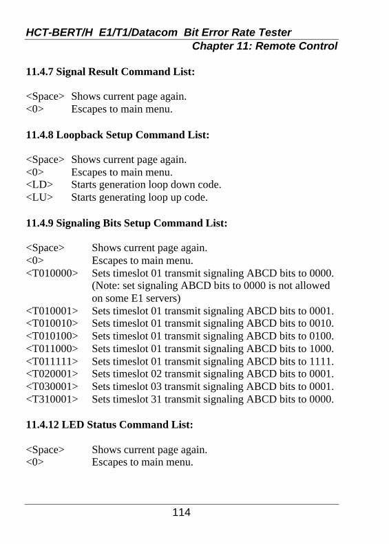
HCT-BERT/H E1/T1/Datacom Bit Error Rate Tester Chapter 11: Remote Control
114
11.4.7 Signal Result Command List: <Space> Shows current page again. <0> Escapes to main menu. 11.4.8 Loopback Setup Command List: <Space> Shows current page again. <0> Escapes to main menu. <LD> Starts generation loop down code. <LU> Starts generating loop up code. 11.4.9 Signaling Bits Setup Command List: <Space> Shows current page again. <0> Escapes to main menu. <T010000> Sets timeslot 01 transmit signaling ABCD bits to 0000. (Note: set signaling ABCD bits to 0000 is not allowed
on some E1 servers) <T010001> Sets timeslot 01 transmit signaling ABCD bits to 0001. <T010010> Sets timeslot 01 transmit signaling ABCD bits to 0010. <T010100> Sets timeslot 01 transmit signaling ABCD bits to 0100. <T011000> Sets timeslot 01 transmit signaling ABCD bits to 1000. <T011111> Sets timeslot 01 transmit signaling ABCD bits to 1111. <T020001> Sets timeslot 02 transmit signaling ABCD bits to 0001. <T030001> Sets timeslot 03 transmit signaling ABCD bits to 0001. <T310001> Sets timeslot 31 transmit signaling ABCD bits to 0000. 11.4.12 LED Status Command List: <Space> Shows current page again. <0> Escapes to main menu.

HCT-BERT/H E1/T1/Datacom Bit Error Rate Tester Chapter 12: User Program Pattern
115
12.1 Introduction To enter the "User Program Pattern" function, press the F1 key from the third menu selection page. When you enter the function, you will see a screen similar to that below:
User programmable pattern #1: Size:[ 08] bits Pattern(in binary)(left first) 10000000......................... FSet FSet FGo FDel FChange 10 21 3Head 4Tail 5Pat #_
User Program Pattern Screen There are three user programmable patterns, which can be sent and analyzed on E1/T1/Datacom TX and RX ports while doing BERT analysis. Please refer to Chapter 6, BERT Analysis, or Chapter 19, Datacom BERT, for more details of the BERT function. The programmable pattern number is show as #1, #2, or #3, on line one of the display. The total repetitive pattern length will be counted automatically and shown as a number size in bits, on line two of the display. The minimum pattern length is one bit, while the maximum pattern length is 32 bits. The left bit of the programmable pattern will be sent or received first, ie. MSB first.

HCT-BERT/H E1/T1/Datacom Bit Error Rate Tester Chapter 12: User Program Pattern
116
12.2 Operation
You may enter "1" to set the current flashing bit in the pattern or you may enter "0" to clear the current flash bit to zero. If you want to move the position of the flashing cursor, just press the "Right" or "Left" arrow keys. Press the "-" key to delete the last bit while the cursor is at the last bit position, then the current bit symbol will change to "." and the length of pattern will decrease by one bit. The minimum length of the programmable repetitive pattern is one bit.
Following are the function key detailed meanings and actions.
[F1]Set 0 Set current bit to 0. [F2]Set 1 Set current bit to 1. [F3]Go Head Move the cursor to the first bit position. [F4]Del Tail Delete the last bit and move the cursor after
the last bit position. [F5]Change Pat# Change setting pattern. It may change to
user programmable pattern #1, #2, or #3. To exit the "User Programmable Pattern" function, press the ESC key.

HCT-BERT/H E1/T1/Datacom Bit Error Rate Tester Chapter 13: Time Slot Setting
117
13.1 Introduction The "Time Slot Setting" function is not available if the E1 or T1 modes are set to unframed or if the modes are set to full channel. Only in n*64K or n*56K channel mode can the timeslot setting function be entered. To enter this function, press the F2 key from the third menu set page. After you enter this function, you will see a screen similar to that below:
T01~07: f [* ]* * * * * * T08~15: * * * * * * * * T16~23: c * * * * * * * T24~31: * * * * * * * * Current:TS01 -> used Total :30 timeslot(s) are used. FSet FSet FProg. F FDefault 1Used 2ByPas3Head 4 5Idle _
E1 (FAS+CAS) Time Slot Setting Screen or
T01~07: f [* ]* * * * * * T08~15: * * * * * * * * T16~23: * * * * * * * * T24~31: * * * * * * * * Current:TS01 -> used Total :31 timeslot(s) are used. FSet FSet FProg. F FDefault 1Used 2ByPas3Head 4 5Idle _
E1 (FAS only) Time Slot Setting Screen
If the mode is set to E1 FAS frame mode, only 31 time slots TS1 to TS31 may be set. If the mode is set to E1 FAS frame and CAS mode, only 30 time slots TS1 to TS15 and TS17 to TS31 are settable. The HCT-BERT/H must also be set to n*56K or n*64K channel mode.

HCT-BERT/H E1/T1/Datacom Bit Error Rate Tester Chapter 13: Time Slot Setting
118
In T1 mode, there are 24 timeslots TS1 to TS24 that may be
selected. If the mode is set to T1 T1DM mode, only 23 time slots TS1 to TS23 are settable.
T01~07: f [* ]* * * * * * T08~15: * * * * * * * * T16~23: * * * * * * * * T24~31: t Current:TS01 -> used Total :24 timeslot(s) are used. FSet FSet FProg. F FDefault 1Used 2ByPas3Head 4 5Idle _
T1 (T1DM) Time Slot Setting Screen In the E1 mode example, there are 31 numbers, star (*), "c", or "p" symbols on the screen. Each one represents the status of one timeslot as follows:
* This time slot is set to used. p This time slot is set to pass through mode (bypass). number This time slot is set to idle mode, and fills in a
programmable number (FF, 7E, etc.) on the transmit side.
c This time slot is E1 CAS mode time slot 16. (not settable)
t This time slot is T1 T1DM mode time slot 24. (not settable)

HCT-BERT/H E1/T1/Datacom Bit Error Rate Tester Chapter 13: Time Slot Setting
119
13.2 Operation There is a flashing cursor (the bracket symbols "[ ]") at any location of the time slot map at any one time. You may press the "Right Arrow", "Left Arrow", "Up Arrow", or "Down Arrow" keys to move the flashing cursor’s position. If you want to change the time slot status, used, idle, or pass through, all you have to do is press the ENTER key. The current status will be changed to idle status (number), pass through status (p symbol), or used status (star symbol), by repeatedly pressing the ENTER key.
Following are the function key detailed meanings and actions.
[F1]Set Used Set current timeslot to used mode. [F2]Set ByPas Set current timeslot to Bypass (Pass
Through) mode. [F3]Prog.Idle Set current timeslot to programmable idle
code mode. [F5]Default Idle Set current timeslot to Default Idle TS mode.
Please refer to Manual Configuration Setup. If the cursor is located at a programmable time slot, the user
can type in number from 0 to 9, or A to F for hexadecimal code. And this code will be filled into this transmitted idle time slot. When performing BERT analysis, you may insert and drop a test pattern into used time slots if you set the channel to n*64K mode or n*56K mode. For more information on changing setup parameters, please refer to Chapter 5, Configuration Setup. To exit the "Time Slot Setting" function, press the ESC key.

HCT-BERT/H E1/T1/Datacom Bit Error Rate Tester Chapter 13: Time Slot Setting
120
This page left blank intentionally.

HCT-BERT/H E1/T1/Datacom Bit Error Rate Tester Chapter 14: Time Slot Map Data
121
14.1 Operation The HCT-BERT/H has the ability to display two frames of E1 32 time slot data in real-time. One frame is FAS, the other is NFAS. From the third menu page, press the F3 key "Time Slot Map Data". If you choose the "Hex" display mode, the screen will display similar to the following:
FAS TS0:9B AA AA AA AA AA AA AA TS8:AA AA AA AA AA AA AA AA TS16:55 AA AA AA AA AA AA AA TS24:AA AA AA AA AA AA AA AA NFAS TS0:5F AA AA AA AA AA AA AA TS8:AA AA AA AA AA AA AA AA TS16:55 AA AA AA AA AA AA AA TS24:AA AA AA AA AA AA AA AA
E1 Time Slot Map Data Screen (Hex) The HCT-BERT/H has the ability to display two frames of T1 24 time slot data in real-time, also. The screen will display similar to the following: F1 TS1 :F AA AA AA AA AA AA AA TS8 :AA AA AA AA AA AA AA AA
TS16:AA AA AA AA AA AA AA AA TS24:AA
F2 TS1 :F AA AA AA AA AA AA AA TS8 :AA AA AA AA AA AA AA AA TS16:AA AA AA AA AA AA AA AA TS24:AA
T1 Time Slot Map Data Screen For readability, the screen will pause for 0.5 second and then the data will be refreshed.

HCT-BERT/H E1/T1/Datacom Bit Error Rate Tester Chapter 14: Time Slot Map Data
122
If we set the display mode to Binary, we can see the bit data for each time slot as in the following display for E1.
FAS: NFAS: TS0 : 10011011 TS0 : 01011111 TS1 : 10101010 TS1 : 10101010 TS2 : 10101010 TS2 : 10101010 TS3 : 10101010 TS3 : 10101010 TS4 : 10101010 TS4 : 10101010 TS5 : 10101010 TS5 : 10101010 <PgUp><PgDn> change page up/down
E1 Time Slot Map Data Screen (Binary) In T1 mode, the display will look similar to that below.
Frame 1: Frame 2: TS1 : 10101010 TS1 : 10101010 TS2 : 10101010 TS2 : 10101010 TS3 : 10101010 TS3 : 10101010 TS4 : 10101010 TS4 : 10101010 TS5 : 10101010 TS5 : 10101010 TS6 : 10101010 TS6 : 10101010 <PgUp><PgDn> change page up/down
T1 Time Slot Map Data Screen (Binary) Use the PgUp and PgDn keys to view the data for other timeslots. To exit the "Time Slot Map Data" function, press the ESC key.

HCT-BERT/H E1/T1/Datacom Bit Error Rate Tester Chapter 15: File Management
123
15.1 Introduction The HCT-BERT/H is capable of storing configuration and BERT results into its internal memory. You may recall this data from memory at a later date. There are ten file locations where the data can be stored. This function is useful for retaining different field test and analysis results. The results will remain in memory even after you turn the unit power off. To enter this function, press the F4 key from the third menu page. There will be a screen display similar to the following:
> File 1 Occupied File 6 ........ File 2 ........ File 7 ........ File 3 ........ File 8 ........ File 4 ........ File 9 ........ File 5 ........ File10 ........ FSel. FSave FRe- FClear F . 1File 2 3Call 4 5 .
File Manager Display Screen 15.2 Operation There will be a flashing cursor at the beginning of one of the ten file locations. The cursor position indicates the selected file. Use the cursor keys to move the cursor to any file location. You may then take one of the following actions, Save, Recall, or Clear, simply by pressing the appropriate function key. If a file location is occupied with previously saved data, its line will show the "Occupied" message. Empty file locations will show as a dotted line.

HCT-BERT/H E1/T1/Datacom Bit Error Rate Tester Chapter 15: File Management
124
If a file location is "Occupied", the only operations allowed are to Recall or Clear. The Recall operation will restore the selected file location’s contents into the HCT-BERT/H’s working memory. The Clear operation will erase the file location contents, freeing it for further Saves. If the file location is empty, you may only do a Save operation, as there is no data to Clear or Recall. The Save will immediately take the working memory contents and place them into the selected file location for later Recall or Clear. The meaning of each function is shown in the following table:
Function Meaning [F1] Sel. File Moves the flashing cursor to the next file location. [F2] Save Saves current configuration parameter and BERT
test results to the location indicated by the flashing cursor.
[F3] Re-call Recalls the stored data from internal file memory location indicated by the flashing cursor.
[F4] Clear Clears the file data from the location indicated by the flashing cursor.
Note: You may also use the up, down, left and right arrow keys to move the flashing cursor’s position. To exit this function, press the ESC key.

HCT-BERT/H E1/T1/Datacom Bit Error Rate Tester Chapter 16: Miscellaneous
125
16.1 Description From the Page 3 Menu, select function F5 Miscellaneous. The following will be displayed:
--------- MISCELLANEOUS ------ F1 : Key Sound Setup F2 : Printer Setup F3 : Clock Setup F4 : Version Display --------------------------------
Miscellaneous Screen The following sections will explain the four miscellaneous functions. 16.2 Key Sound Setup The beep sound when a key is depressed can be turned OFF or ON. From the Miscellaneous Menu press the F1 key. The following will be displayed:
KEY SOUND SETUP Turn ON/OFF the beep sound, When key is pressed.
Key Sound Setup Screen Toggle between ON and OFF, using left and right arrow keys, to enable or disable the Beep sound and then press the ESC key.

HCT-BERT/H E1/T1/Datacom Bit Error Rate Tester Chapter 16: Miscellaneous
126
16.3 Print function setting The mode of printing may be selected between normal or condensed print. From the Miscellaneous Menu press the F2 key. The following will be displayed.
PRINTER SETUP Printer type : NORMAL/CONDENSE
Printer Setup Screen Toggle between NORMAL and CONDENSE, using the left and right arrow keys, to enable or disable condensed printing and then press the ESC key. 16.4 Clock Setup The internal clock of the HCT-BERT/H may be set through this menu. From the Miscellaneous Menu press the F3 key. The following will be displayed:
Current Date: 2002-07-21 Time: 14:39:53 Setting Date: 02-07-21(yy-mm-dd) Time: 14:39:07(hh:mm:ss) Event Time: 00:00:00(hh:mm:ss) * Press <ENTER> to confirm every item. * Press <ESC> to exit.
Clock Setup Screen

HCT-BERT/H E1/T1/Datacom Bit Error Rate Tester Chapter 16: Miscellaneous
127
From the cursor position, either change the entry or press ENTER to accept the current value. Only the fields for setting date & time and the event time may be edited. Press ESC anytime to exit. In order for changes to be saved, you must press ENTER on all of the remaining fields. After completing all of the entry fields, the "Press <F1> key to confirm this function" message will be displayed. By confirming this function, the entry placed in the "setting date" and "time" fields will become the HCT-BERT/H’s current date and time. When the event time equals the current time, any process you may be running, such as an emulation program, will stop automatically. 16.5 Version Display
The hardware, software versions, and serial number of the HCT-BERT/H may be displayed through this function. Press the F4 key from the miscellaneous menu, a similar screen will be displayed:
Firmware version: 4H.62-10 Hardware version: L2.4 + L3.4 Serial Number : 3004567 < press any key to exit >
Version Display Screen
Press any key to exit back to the miscellaneous menu. Press the ESC key to exit the miscellaneous menu.

HCT-BERT/H E1/T1/Datacom Bit Error Rate Tester Chapter 16: Miscellaneous
128
This page left blank intentionally.

HCT-BERT/H E1/T1/Datacom Bit Error Rate Tester Chapter 17: Self Test
129
17.1 Description The diagnostic self tests performed by the HCT-BERT/H are selected from the fourth menu page by the F1 key. From the Self Test menu, F1 and F2 select the SINGLE MODE and CONTINUOUS MODE tests respectively. The same tests are available under both SINGLE MODE and CONTINUOUS MODE. The difference between the two modes is that in SINGLE MODE, the tests are run for one pass only. In CONTINUOUS MODE, the tests are run repeatedly until a key is pressed when the "press any key to exit." message is displayed, the unit is powered off, or the battery becomes too low for the unit to function properly. The tests confirm proper operation of the HCT-BERT/H's Central Processing Unit (CPU), the Read Only Memory (ROM), and the Random Access Memory (RAM) as well as internal loop-back tests for the communications interface. Selecting F3, runs the Printer Port Test. The F4 key selects the Liquid Crystal Display (LCD) for testing, while F5 will test the tactile membrane Keyboard. 17.2 Self Test Single Mode From the Page 4 MENU, select F5, Self Test.
--------- SELF TEST ----------- F1 : Self Test Single Mode F2 : Self Test Continue Mode F3 : Print Port Test F4 : LCD Test F5 : Keyboard Test MORE : -------------------------------
Self Test Screen

HCT-BERT/H E1/T1/Datacom Bit Error Rate Tester Chapter 17: Self Test
130
Selecting F1 from the Self Test Menu will run the internal test routines for one pass. The resultant display will look like this.
--------- SELF TEST ------------ System ROM : Pass! System RAM : Pass! Internal - DTE Port : DCE Port : ----Press any key to exit.--------
Self Test Single results Screen 17.3 Self Test Continuous Mode Selecting F2 Self Test Continue Mode, from the Self Test Menu, will run the internal tests continuously, non-stop. In continuous mode, the display test is added to the test routine. To exit continuous self test, press any key when you see the "Press any key to exit." message on the screen. 17.4 Print Port Test Selecting F3 Print Port Test, will print an ASCII CODE pattern of printable characters (20H---7FH) to any attached printer. If no printer is attached to the parallel port, a PRINTER BUSY message will be displayed on the LCD screen.

HCT-BERT/H E1/T1/Datacom Bit Error Rate Tester Chapter 17: Self Test
131
17.5 LCD Test Selecting F4 LCD Test, will test the LCD display in the following manner. All pixels will light ON and then OFF. Then the Display will show the character set with NORMAL, FLASHING, and REVERSE video attributes.
-------- DISPLAY TEST --------- !"#$%&'( )*+,-./0123456789:;<=>? @ABCDEFGHIJKLMNOPQRSTUVWXYZ[\]^_ `abcdefghijklmnopqrstuvwxyz{|}~© NORMAL FLASHING REVERSE Press any key to exit.
Display Test results Screen 17.6 Keyboard Test F5 Keyboard Test will bring up the keyboard test from the Self Test menu. The display should resemble the following:
--------- KEYBOARD TEST -------- * * ***** * ************ ************ ************ --- Press SHIFT-ESC to exit ----
Keyboard Test Screen The relative key positions will be shown on the LCD. With every press of a key on the keyboard, the relative position markers will change to a square box, indicating proper operation of the key. To EXIT the test at any time, press SHIFT and ESC.

HCT-BERT/H E1/T1/Datacom Bit Error Rate Tester Chapter 17: Self Test
132
This page left blank intentionally.

HCT-BERT/H E1/T1/Datacom Bit Error Rate Tester Chapter 18: Sa Bits Setup
133
18.1 Introduction The Sa4 to Sa8 are spare bits that may be recommended by ITU-T for use in specific point-to point applications. When they are not used, they should be set to 1 on links crossing an international border. The Sa4 to Sa8 bits are allocated in E1 format timeslot 0, please refer to Table 1-4 for E1 frame format timeslot 0 bit allocations.
Only when the HCT-BERT/H is set to E1(CEPT) mode can this feature be entered.
When the screen of the HCT-BERT/H is on the fourth main
menu page, pressing the F2 key will enter Sa Bits Setup. After entering this function, the screen should show a display as follows:
TX NFAS FRAMES TS0 Sa4~8 [11111] RX FRAME-1:11111 FRAME- 9:11111 FRAME-3:11111 FRAME-11:11111 FRAME-5:11111 FRAME-13:11111 FRAME-7:11111 FRAME-15:11111 FSet FSet F<- F-> F . 11 20 3 4 5 .
Sa bits Setup Screen This screen shows settings of current transmission Sa bits on the first line, and shows the real-time status of received Sa bits on each odd E1 frame on the following four lines.

HCT-BERT/H E1/T1/Datacom Bit Error Rate Tester Chapter 18: Sa Bits Setup
134
18.2 Sa Bits Transmission Setting The flashing cursor is located on the transmission Sa Bits field, and can be moved to another location by press the right arrow, left arrow F3, or F4 keys. The first location is Sa4, the second location is Sa5, the third location is Sa6, the fourth location is Sa7, and the last location is Sa8. All of the setting will effect every Sa bit on each transmitted odd frame.
The setup function key definitions are as follows: [F1] Set 1: Set current TX Sa bit to 1. [F2] Set 0: Set current TX Sa bit to 0. [F3] <-: Move current cursor location to previous TX Sa bit. [F4] ->: Move current cursor location to next TX Sa bit. Other keys that have functions are: 1 Set current TX Sa bit to 1. 0 Set current TX Sa bit to 0. Left Arrow Move current cursor location to previous TX Sa bit. Right Arrow Move current cursor location to next TX Sa bit. ESC Exit this function.

HCT-BERT/H E1/T1/Datacom Bit Error Rate Tester Chapter 18: Sa Bits Setup
135
18.3 Sa bits Monitor
The Sa4, Sa5, Sa6, Sa7, and Sa8 bits are located at each odd E1 frame timeslot 0. There are eight E1 frames that have Sa bits in one E1 multiframe. Received Sa bits are shown in real-time on the screen, line 2 to line 5 as follows:
RX FRAME-1:11111 FRAME- 9:11111 FRAME-3:11111 FRAME-11:11111 FRAME-5:11111 FRAME-13:11111 FRAME-7:11111 FRAME-15:11111
The 1s or 0s following the FRAME-# are bits of Sa4, Sa5, Sa6, Sa7, and Sa8, which are contained at that frame.

HCT-BERT/H E1/T1/Datacom Bit Error Rate Tester Chapter 18: Sa Bits Setup
136
This page left blank intentionally.

HCT-BERT/H E1/T1/Datacom Bit Error Rate Tester Chapter 19: Datacom BERT
137
19.1 Introduction The HCT-BERT/H has the ability to do Datacom BERT (BERT on data port). The speeds are multiples of 64K or 56K, which may be up to 2048K bit/s. The available interfaces are RS-530/RS-449/X.21, V.35, and RS-232. To enter the "Datacom BERT" function, press the F3 key from the fourth menu selection page. The Datacom BERT function will analyze datacom line performance in common display mode or ITU-T G.821 mode, and generate specific patterns on the data port. 19.2 Configuration Setup After entering this function, the screen should show a display similar to below:
----- BERT ON DATA CONFIG ------ Data Port : DTE Interface : RS-449/530/X.21 Pattern : QRSS Test Period : Continuous Alarm : 1 bit Datacom Baud : 64K (N64) Datacom Tx Clk : Internal
Configuration Setup Screen
These are the main settings of the HCT-BERT/H and will effect associated operations. The inverted cursor block is located on the first parameter, DTE. You can move the cursor up and down by pressing the up and down arrow keys. You may change the current parameter, where the cursor is located, by pressing the right or left arrow key. Press the PgDn (page down) or PgUp (page up) key to see next page or previous page of settings. Pressing the HOME key will move the

HCT-BERT/H E1/T1/Datacom Bit Error Rate Tester Chapter 19: Datacom BERT
138
cursor to the top page and top parameter. Pressing the END key will move the cursor to the last page and bottom parameter. The available settings and meanings of each configuration parameter in the "BERT ON DATA CONFIG" function are as follows: Setting Parameter Description Data Port: DTE HCT-BERT/H is configured as DTE
device. DCE HCT-BERT/H is configured as DCE
device. Interface: RS-449/530
/X.21 HCT-BERT/H’s data port is set to RS-449, RS-530, or X.21 mode. (cable)
RS-232 HCT-BERT/H’s data port is set to RS-232 mode. (cable)
V.35 HCT-BERT/H’s data port is set to V.35 mode. (cable)
Pattern: 63 Pseudo random pattern: 2e6-1 127 Pseudo random pattern: 2e7-1 511 Pseudo random pattern: 2e9-1 (O.153) 2047 Pseudo random pattern: 2e11-1
(O.152 AND O.153) 2e15-1 standard
Pseudo random pattern: 2e15-1 (O.151)
(HCT-BERT/H will transmit and analyze this pattern into datacom port)
2e15-1 non-standard
Pseudo random pattern: 2e15-1 (O.151 inverted)
2e20-1 standard
Pseudo random pattern: 2e20-1 (O.153)
2e20-1 non-standard
Pseudo random pattern: 2e20-1 (inverted)
QRSS Pseudo random pattern: 2e20-1 (O.151 QRSS)
2e23-1 standard
Pseudo random pattern: 2e23-1 (O.151)

HCT-BERT/H E1/T1/Datacom Bit Error Rate Tester Chapter 19: Datacom BERT
139
2e23-1 non-
standard Pseudo random pattern: 2e23-1 (O.151 inverted)
All One Repetitive pattern: all ones (11111...) All Zero Repetitive pattern: all zeros (00000...) ALT(0101) Repetitive pattern: alternating ones and
zeros (10101010...) 3 in 24 Repetitive pattern: 3 in 24 1 in 16 Repetitive pattern: 1 in 16 1 in 8 Repetitive pattern: 1 in 8 1 in 4 Repetitive pattern: 1 in 4 User Prog #1 User programmable repetitive pattern
#1. The length of this pattern may be set from 1 to 32 bits. Please refer to Chapter 11 for details.
User Prog #2 User programmable repetitive pattern #2. The length of this pattern may be set from 1 to 32 bits. Please refer to Chapter 11 for details.
User Prog #3 User programmable repetitive pattern #3. The length of this pattern may be set from 1 to 32 bits. Please refer to Chapter 11 for details.
Continuous The BERT test will run forever Test Period: 1 Minute BERT will run for one minute. 15 Minutes BERT will run for fifteen minutes. 30 Minutes BERT will run for half an hour. 1 Hour BERT will run for an hour. 24 Hours BERT will run for one day. Datacom Baud
N64K The speeds available on 64K mode are 64K, 128K, 192K, 256K, 320K, 384K, 448K, 512K, 576K, 640K, 704K, 768K, 832K, 896K, 960K, 1024K, 1088K, 1152K, 1216K, 1280K, 1344K, 1408K, 1472K, 1536K, 1544K, 1600K, 1664K,

HCT-BERT/H E1/T1/Datacom Bit Error Rate Tester Chapter 19: Datacom BERT
140
1728K, 1792K, 1856K, 1920K, 1984K, 2048K
N56K, 1544K
The speeds available on 56K mode are 56K, 112K, 168K, 224K, 280K, 336K, 392K, 448K, 504K, 560K, 616K, 672K, 728K, 784K, 840K, 896K, 952K, 1008K, 1064K, 1120K, 1176K, 1232K, 1288K, 1344K, 1400K, 1456K, 1512K, 1544K, 1568K, 1624K, 1680K, 1736K, 1792K
Internal Tx clock sets to internal. Int. INV. (Internal Inverted) Tx clock sets to
internal and its polarity is inverted. External Tx clock sets to eternal.
Datacom Tx Clk (Datacom Transmission Clock)
Ext. INV. (External Inverted) Tx clock sets to external and its polarity is inverted.
External Tx clock sets to eternal. Datacom Rx Clk: (Datacom Receiver Clock)
Ext. INV. (External Inverted) Tx clock sets to external and its polarity is inverted.

HCT-BERT/H E1/T1/Datacom Bit Error Rate Tester Chapter 19: Datacom BERT
141
Normal The sense of Tx clock sets to normal.
(Transmit on falling edge of transmit clock.)
TxClk Sense: (Sense of Transmit Clock)
Inverted The sense of Tx clock sets to invert. (Transmit on rising edge of transmit clock.)
Ins Error Rate:
Single Will force a single error when you press the Force Error Key.
1e-3 Will force errors continuously at transmit rate of 1e-3.
1e-4 Will force errors continuously at transmit rate of 1e-4.
1e-5 Will force errors continuously at transmit rate of 1e-5.
1e-6 Will force errors continuously at transmit rate of 1e-6.
1e-7 Will force errors continuously at transmit rate of 1e-7.
Disable Always transmit out testing pattern. Datacom Flow C(ontrol)
CTS/RTS ON
When HCT-BERT/H is set to DTE mode, it will transmit out testing pattern if CTS active; when HCT-BERT/H is set to DCE mode, it will transmit out testing pattern if RTS active. Otherwise, HCT-BERT/H will not transmit out testing pattern.
Print Interval:
Disable The printer will not print out results automatically.
5 Min The printer will print out test results every five minutes.
10 Min The printer will print out test results every ten minutes.

HCT-BERT/H E1/T1/Datacom Bit Error Rate Tester Chapter 19: Datacom BERT
142
15 Min The printer will print out test results
every fifteen minutes. 30 Min The printer will print out test results
every half an hour 60 Min The printer will print out test results
every hour. Print On Error:
Disable The printer will not print out current test results while errors are received
Enable The printer will print out current test results while errors are received.
Pressing the ESC key will exit this function. Press the RUN key to run Datacom BERT analysis. 19.3 Clock setting
The clock source setting of Datacom BERT depends upon the user’s application. If the external device can supply the clock source, then the HCT-BERT/H datacom transmission clock should be set to external, otherwise, the HCT-BERT/H must supply its internal transmission clock for the external device. The HCT-BERT/H receiver clock is always set to external. Both of the clock polarities can be set to normal or inverted. The selection table is depicted below:
Mode Clock Source
Selection TX RX TX Clock
Source RX Clock Source
Internal TD XTC(internal) TX Clock External TD TC
DTE
RX Clock External RD RC
Internal RD TC or RC(internal)
TX Clock
External RD XTC
DCE
RX Clock External TD XTC

HCT-BERT/H E1/T1/Datacom Bit Error Rate Tester Chapter 19: Datacom BERT
143
19.4 Datacom BERT Analysis When the screen of the HCT-BERT/H is on Datacom BERT Configuration, pressing the RUN key will enter and run the Datacom BERT analysis function. After entering the function, the screen should show a display similar to below:
LOGIC Elapsed:00d00h00m51s Receive Count = 100602189 Errors = 0 Error Sec = 0 Error Free Sec = 51 Error Rate = 0.0e-00 FDisp FForceFEr R FResyncFResetM 1Page12 30 4 5 O
Logic Display Screen The top-right message, elapsed time, shows the duration of the current test. This analysis mode can be paused by pressing the RUN key, and continued by again pressing the RUN key. The bottom two lines show available function keys by their abbreviation. Pressing the MORE key will display additional function keys. By simply pressing the PgUp (page up) or PgDn (page down) keys, two of the display type screens can be viewed. The second screen is shown on the following page:

HCT-BERT/H E1/T1/Datacom Bit Error Rate Tester Chapter 19: Datacom BERT
144
LOGIC G.821 Elapsed:00d00h00m51s Available Sec. = 51 100% Degraded Min. = 0 % Severely ErrSec= 0 % Errored Second = 0 % Unavailable Sec= 0 % FDisp FForceFEr R FResyncFResetM 1Page12 30 4 5 O
Logic G.821 Display Screen If you desire a hard copy print out of all the test results, connect the printer adapter cable from the printer port to a printer and press the PRINT key. You may also set testing duration, time interval to print results, or print when errors occurs. 19.5 Performance The HCT-BERT/H analyzes and displays received Datacom BERT on the LCD screen. This section depicts all of the on screen abbreviations and meanings. In "Logic" Format:
Receive Count : Received Total Logic Bit Counter Errors : Received Error Logic Bit Counter Error Sec : Received Logic Bit Error Seconds Error Free Sec : Received Logic Bit Error Free Seconds Error Rate : Received Logic Error Rate (calculated of dividing received error logic bit counter by total received logic bit counter)
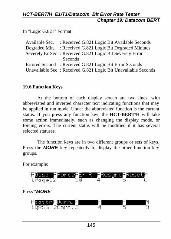
HCT-BERT/H E1/T1/Datacom Bit Error Rate Tester Chapter 19: Datacom BERT
145
In "Logic G.821" Format:
Available Sec. : Received G.821 Logic Bit Available Seconds Degraded Min. : Received G.821 Logic Bit Degraded Minutes Severely ErrSec : Received G.821 Logic Bit Severely Error Seconds Errored Second : Received G.821 Logic Bit Error Seconds Unavailable Sec : Received G.821 Logic Bit Unavailable Seconds
19.6 Function Keys At the bottom of each display screen are two lines, with abbreviated and inverted character text indicating functions that may be applied in run mode. Under the abbreviated function is the current status. If you press any function key, the HCT-BERT/H will take some action immediately, such as changing the display mode, or forcing errors. The current status will be modified if it has several selected statuses. The function keys are in two different groups or sets of keys. Press the MORE key repeatedly to display the other function key groups. For example:
FDisp FForceFEr R FResyncFResetM 1Page12 30 4 5 O
Press "MORE"
FpattnFDurn.F F F M 1QRSS 2Cont.3 4 5 O

HCT-BERT/H E1/T1/Datacom Bit Error Rate Tester Chapter 19: Datacom BERT
146
Following are the function key detailed meanings and actions.
Group 1 [F1]Disp. Display Format Page1 Changes the display format to page 1 (G.821 mode). Page2 Changes the display format back to page 2 (common mode). [F2]Forced Force a Single Error Insert a single error immediately. [F3]Er R Automatic Forced Error Rate 0 Disable automatic forced errors action. 1e-3 Automatic forced error rate is set at a rate of 1e-3. 1e-4 Automatic forced error rate is set at a rate of 1e-4. 1e-5 Automatic forced error rate is set at a rate of 1e-5. 1e-6 Automatic forced error rate is set at a rate of 1e-6. 1e-7 Automatic forced error rate is set at a rate of 1e-7. [F4]ReSyn Re-sync framing [F5]Reset Reset all test results and clear all of the received
counters and timers. Group 2 (after pressing the MORE key) [F1]Pattn Pattern 63 63 127 127 511 511(O.153) 2047 2047(O.152 AND O.153) 2e15s 2e15-1(O.151) 2e15n 2e15-1(O.151 inverted)

HCT-BERT/H E1/T1/Datacom Bit Error Rate Tester Chapter 19: Datacom BERT
147
2e20s 2e20-1(O.153) 2e20n 2e20-1(inverted) QRSS QRSS(O.151 QRSS) 2e20s 2e20-1(O.151) 2e20n 2e20-1(O.151 inverted) All 1 All Ones All 0 All Zeros 0101 Alternate(0101) 3in24 3 in 24 1in16 1 in 16 1 in8 1 in 8 1 in4 1 in 4 User1 User Programmable Pattern #1. User2 User Programmable Pattern #2. User3 User Programmable Pattern #3. [F2]Durn. Test Duration Cont. Continuous 1 Min 1 Minute 15Min 15 Minutes 30Min 30 Minutes 60Min 1 Hour 24Hrs 24 Hours Other keys that have functions while running BERT:
SPACE Insert single error on BERT Analysis function. ESC Press the first ESC key will stop running and enter
Examine Analysis mode. The user may press the PgUp or PgDn key to review two pages of results. Pressing the PRINT key will print out the testing results. Pressing the ESC key again will exit and go to the main menu.

HCT-BERT/H E1/T1/Datacom Bit Error Rate Tester Chapter 19: Datacom BERT
148
This page left blank intentionally.

HCT-BERT/H E1/T1/Datacom Bit Error Rate Tester Chapter 20: Low Speed Datacom BERT
149
20.1 Low Speed Datacom BERT SETUP
20.1.1 : Setup
From the fourth main menu page, press the F4 key. The following screen will be displayed. ----- LOW SPEED BERT CONFIG ----- Data Port : DTE Interface : RS-449/530/X.21 Pattern : 511 Block Size : 1000bits Test Period : Continuous Alarm : 1 bit Protocol : Sync(BSC)
Low Speed Datacom BERT Setup Screen
Using the "òò" arrow key, further menu items will scroll up the screen. Move the arrow down to the last menu item. The screen should look as follows. ----- LOW SPEED BERT CONFIG ----- Parity : [None] Tx Clock : DTE Xon/off : Disable Flow Control : Disable Print Interval: Disable Print on Error : Disable -------------------------------
Low Speed Datacom BERT Setup Screen (cont.)
HCT-BERT/H E1/T1/Datacom Bit Error Rate Tester Chapter 20: Low Speed Datacom BERT
150
Return the cursor to the top of the screen (to the "Data Port" parameter setting) by using the "ññ" arrow key or press HOME.
20.1.2 : Data Port Setting Use the "ðð" arrow key to select the available data port
mode for BERT. The HCT-BERT/H can perform in DTE or DCE modes. Select DTE mode if connecting to Data Communication Equipment such as MODEMs. Select DCE mode if connecting to Data Terminal Equipment such as display terminals or PC Com ports.
20.1.3 : Interface Setting
Use the "ðð" arrow key to set the available interface type. They include RS-232, V.35, and RS-449/530/X.21 types. Use the appropriate interface adapter cable for the selected interface type.
20.1.4 : Pattern Setting
Use the "ðð" arrow key to select the available data patterns for BERT. They include 63, 511, 2047, "Fox" (ASCII), Space (all zeros), Mark (all ones), and Alt (alternate ones and zeros).
20.1.5 : Block Size Setting
Hi-light the parameter setting for Block Size and press the "ðð" arrow key to set the block size to either the pattern size or to 1000 bits.
20.1.6 : Duration Setting
Follow the same keystroke procedures and set the Duration of bit counts to 103, 104, 105, 106, 107, 108 bits, or to minutes duration of 1, 5, 10, 15, 30, 60 minutes or set to run continuously.

HCT-BERT/H E1/T1/Datacom Bit Error Rate Tester Chapter 20: Low Speed Datacom BERT
151
20.1.7 : Alarm Setting
The alarm settings may be disabled or set to trigger after 1, 10, 100, or 1000 bits in error.
20.1.8 : Protocol Setting
The HCT-BERT/H supports both ASYNC and SYNC protocols. Select the protocol for your application.
20.1.9 : Speed Setting
Select the appropriate speed for your application. ASYNC : 50, 75, 110, 150, 200, 300, 600, 1200, 1800,
2000, 2400, 3200, 3600, 4800, 7200, 9600, 12k, 14.4k, 16k, 19.2k, 28.8k, 38.4k, 48k, 57.6k, 64k, 72k, 115.2kbps.
SYNC : 150, 200, 300, 600, 1200, 1800, 2000, 2400,
3200, 3600, 4800, 7200, 9600, 12k, 14.4k, 16k, 19.2k, 28.8k, 38.4k, 48k, 57.6k, 64k, 72kbps.
20.1.10 : Bits Setting
When using ASYNC protocol, the HCT-BERT/H supports 5, 6, 7, or 8 bits. Only 8 bits are supported in SYNC mode. When choosing SYNC protocol, 8 bits will automatically be set.
20.1.11 : Parity Setting
When using ASYNC protocol, the HCT-BERT/H supports a parity setting of ODD, EVEN or NONE. No Parity bits are supported in SYNC mode. When choosing SYNC protocol, no parity bits will apply.
20.1.12 : Stop Bits Setting
Stop bits only apply when using ASYNC protocol settings. The stop bits may be set to 1, 1.5, or 2.
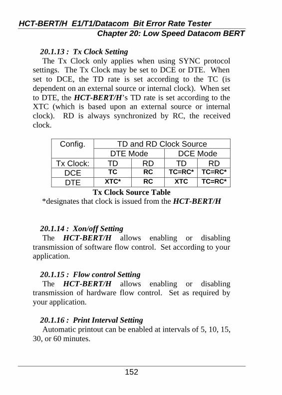
HCT-BERT/H E1/T1/Datacom Bit Error Rate Tester Chapter 20: Low Speed Datacom BERT
152
20.1.13 : Tx Clock Setting
The Tx Clock only applies when using SYNC protocol settings. The Tx Clock may be set to DCE or DTE. When set to DCE, the TD rate is set according to the TC (is dependent on an external source or internal clock). When set to DTE, the HCT-BERT/H’s TD rate is set according to the XTC (which is based upon an external source or internal clock). RD is always synchronized by RC, the received clock.
TD and RD Clock Source Config.
DTE Mode DCE Mode Tx Clock: TD RD TD RD
DCE TC RC TC=RC* TC=RC*
DTE XTC* RC XTC TC=RC*
Tx Clock Source Table *designates that clock is issued from the HCT-BERT/H
20.1.14 : Xon/off Setting The HCT-BERT/H allows enabling or disabling
transmission of software flow control. Set according to your application.
20.1.15 : Flow control Setting
The HCT-BERT/H allows enabling or disabling transmission of hardware flow control. Set as required by your application.
20.1.16 : Print Interval Setting
Automatic printout can be enabled at intervals of 5, 10, 15, 30, or 60 minutes.

HCT-BERT/H E1/T1/Datacom Bit Error Rate Tester Chapter 20: Low Speed Datacom BERT
153
20.1.17 : Print On Error Setting
By enabling this parameter, the HCT-BERT/H will print whenever an error condition occurs.
20.2 Running Low Speed Datacom BERT
20.2.1 : Start Bit Error Rate Testing
After all parameters are set and connections made, BERT testing is started by pressing the RUN key. The following screen will be displayed.
-BERT/BLERT- Sp:9600 Pat:511 Bit Tx= 170024|BlkTx= 170 Bit Rx= 169968|BlkRx= 169 Bit Er= 0|BlkEr= 0 Bit Er/R=0.0e-00|ErSec= 0 Forced Er= 0| 0D00:00:18 FForceFForceFResetF 11 Err 25 Err 3Count4
Low Speed Datacom BERT Running
While BERT is running the following function keys are in effect: F1
Forces a single bit error. F2
Forces five(5) single bit errors. F3
Resets the timer and all bit/block counters to zero. ESC
Exits BERT testing.

HCT-BERT/H E1/T1/Datacom Bit Error Rate Tester Chapter 20: Low Speed Datacom BERT
154
RUN
Halts BERT testing. HALT will be displayed. At this point, a printout may be done by pressing the PRINT key. Pressing RUN again will restart testing.
20.2.2 : Communication Line Quality Test
To test and check the quality of a transmission line, the HCT-BERT/H sends continuous data which is then looped back, received, and compared. Any discrepancies indicate that an error has occurred.
a: Available BAUD Rates for testing:
ASYNC : 50 bps - 128 Kbps, SYNC (BSC) : 150 bps - 72 Kbps.
b: Available test transmission PATTERNS :
63/511/2047, MARK (all 1's), SPACE (all 0's), FOX (ASCII), and ALT (0101).
20.2.3 : Connections There are two recommended connection methods. The first requires two HCT-BERT/Hs, one connected on each side of the communication line via a "straight" or "null" connection. In other words, the transmit signal from one unit is connected to the receive input of the other unit and visa versa. The second method requires only one HCT-BERT/H on one end of the communication line and a physical loop back at the other end. The HCT-BERT/H can transmit the selected pattern continuously, will synchronize with the received data and count bit errors.

HCT-BERT/H E1/T1/Datacom Bit Error Rate Tester Chapter 20: Low Speed Datacom BERT
155
By looping back at different points on the data link or by testing with various BAUD rates, the BERT test function can determine line quality, acceptable band width, or serve as an aid in troubleshooting and isolating cable/connector deficiencies.
20.2.4 : Setup
When using an HCT-BERT/H on both sides of the communication line, set the parameters SELECT PATTERN, DATA BLOCK, SPEED, CLOCK (if sync), and ALARM TIMER to identical settings on both units. Connect the units such that transmit pin of one unit is connected to the receive pin of the other. If using a single unit, set a loop back on the transmission cable from the receive pin to the transmit pin, or set the remote device to loop back mode.
20.2.5 : Testing
To start testing, if using two units, press the RUN key at the same time on both units on each end of the communications line. Otherwise, just press the RUN on the single unit. The length of testing time is determined by the setup information. The advantage of using two units for testing is that the sending and receiving channels can be tested simultaneously since each HCT-BERT/H contains its own transmitter and receiver.

HCT-BERT/H E1/T1/Datacom Bit Error Rate Tester Chapter 20: Low Speed Datacom BERT
156
This page left blank intentionally.

HCT-BERT/H E1/T1/Datacom Bit Error Rate Tester Appendix A: Acronyms and Abbreviations
157
ADC Analog to Digital Converter AGC Automatic Gain Control AIS Alarm Indication Signal ALBO Automatic Line Build Out ALOS Analog Loss of Signal AMI Alternate Mark Inversion ANSI American National Standards Institute B8ZS Binary with 8 Zero Substitution BER Bit Error Rate BERR Bit Error Counter BFA Basic Frame Alignment BOP Bit-Oriented Protocol BPV Bipolar Violation CAS Channel Associated Signaling ITU-T International Telegraph and Telephone Consultative
Committee CCS Common Channel Signaling CERR CRC Errors CGA Carrier Group Alarm CI Customer Installation COFA Change of Frame Alignment CRC Cyclic Redundancy Check CSU Channel Service Unit DAC Digital to Analog Converter DCS Digital Cross-Connect System DDS Digital Data System DMI Digital Multiplexed Interface DPLL Digital Phase Locked Loop DS1 Digital Signal Level 1 DSU Data Service Unit ESF Extended Superframe EXZ Excessive Zeros FAS Frame Alignment Sequence (E1 Format) FCC Federal Communications Commission

HCT-BERT/H E1/T1/Datacom Bit Error Rate Tester Appendix A: Acronyms and Abbreviations
158
FCS Frame Check Sequence FDL Facility Data Link FEBE Far End Block Error FERR Framing Bit Error FPS Frame Pattern Sequence (EFS Format) HCDS High-Capacity Digital Service HDB3 High-Density Bipolar of order 3 ICOT Intercity and Outstate Trunk IDLC Integrated Digital Loop Carrier ISDN Integrated Service Digital Network JAT Jitter Attenuator JCLK Jitter Attenuated Clock JTAG Joint Test Action Group LBO Line Build Out LCV Line Code Violation LEC Local Exchange Carrier LIU Line Interface Unit LOAS Loss of Analog Signal LOF Loss of Frame LOS Loss of Signal -DS1 LSB Least Significant Bit MAIS Multiframe AIS MART Maximum Average Reframe Time MAS Multiframe Alignment Sequence (CAS Format) MAT Metropolitan Area Trunk MERR MFAS Error MFAS Multiframe Alignment Sequence (CRC4 format) MOP Message-Oriented Protocol MOS Message Oriented Signaling MSB Most Significant Bit MVIP Multi-Vendor Integration Protocol MYEL Multiframe Yellow Alarm NI Network Interface NRZ Non-Return to Zero

HCT-BERT/H E1/T1/Datacom Bit Error Rate Tester Appendix A: Acronyms and Abbreviations
159
OOF Out of Frame PDV Pulse Density Violation PIC Polyethylene-insulated Cable PLCC Plastic Leaded Chip Carrier PLL Phase Locked Loop PM Performance Monitoring PRBS Pseudo-Random Bit Sequence PRI Primary Rate Interface PRM Performance Report Message RAI Remote Alarm Indication RBOP Bit-Oriented Protocol Detector RBS Robbed Bit Signaling RCVR Receiver RDL1 Receive Data Link 1 RDL2 Receive Data Link 2 RDL3 External Receive Data Link RFRAME Receive Framer RJAT Receive Jitter Attenuator RLIU Receive Line Interface Unit RMAIS Receive Multiframe AIS RPDV Receive Pulse Density Violation RPLL Receive Phase Locked Loop RSB Receive System Bus RSBI Receive System Bus Interface RSIG Receive Signaling Buffer RSLIP Receive Slip Buffer RXCLK Receive Clock RZCS AMI/HDB3/B8ZS Line Decoder QRSS Quasi-Random Signal Source SEF Severely Erred Framing Event SERR CAS Error SF Super Frame SLC Subscriber Loop Carrier TAP Test Access Port

HCT-BERT/H E1/T1/Datacom Bit Error Rate Tester Appendix A: Acronyms and Abbreviations
160
TBOP Bit Oriented Protocol Formatter TDL1 Transmit Data Link 1 TDL2 Transmit Data Link 2 TDL3 External Transmit Data Link TDM Time Division Multiplexed TSB Transmit System Bus TSBI Transmit System Bus Interface TJAT Transmit Jitter Attenuator TLIU Transmit Line Interface Unit TLOS Transmit Loss of Signal TSB Transmit System Bus TSIC Time Slot Inter-Change TSIG Transmit Signaling Buffer TSLIP Transmit Slip Buffer TZCS AMI/HDB3/B8ZS Line Encoder UI Unit Interval UMC Unassigned Mux Code UNICODE Universal Trunk Out Of Service Code UTP Unshielded Twisted Pair VCO Voltage Controlled Oscillator VCXO Voltage Controlled Crystal Oscillator VGA Variable Gain Amplifier XMTR Digital Transmitter YEL Yellow Alarm ZCS Zero Code Suppression

HCT-BERT/H E1/T1/Datacom Bit Error Rate Tester Appendix B: Cable Pin Out
161
Part#: 58-H2MD2M000, Cable, HD26 Male-DB25 Male, RS530, 1M Part#: 58-H2MD2F000, Cable,HD26 Male-DB25 Female, RS530, 1M HD26(Male) PIN# <-> PIN# DB25(Male/Female)
TD(A) 2 <-> 2 TD(B) 11 <-> 14 RD(A) 3 <-> 3 RD(B) 21 <-> 16 RTS(A) 4 <-> 4 RTS(B) 13 <-> 19 CTS(A) 5 <-> 5 CTS(B) 14 <-> 13 DSR(A) 6 <-> 6 DSR(B) 22 <-> 22 DTR(A) 20 <-> 20 DTR(B) 12 <-> 23 DCD(A) 8 <-> 8 DCD(B) 26 <-> 10 TC(A) 15 <-> 15 TC(B) 23 <-> 12 RC(A) 17 <-> 17 RC(B) 25 <-> 9 XTC(A) 24 <-> 24 XTC(B) 16 <-> 11 XRC(A) 9 <-> 21 XRC(B) 18 <-> 18 GND 7 <-> 7 FGND 1 <-> 1
Note: The (A)(B) of the same name must be a twisted pair.

HCT-BERT/H E1/T1/Datacom Bit Error Rate Tester Appendix B: Cable Pin Out
162
Part#: 58-H2MD3M000, Cable, HD26 Male-DB37 Male, RS449, 1M Part#: 58-H2MD3F000, Cable,HD26 Male-DB37 Female, RS449, 1M HD26(Male) PIN# <-> PIN# DB37(Male/Female)
TD(A) 2 <-> 4 SD(A) TD(B) 11 <-> 22 SD(B) RD(A) 3 <-> 6 RD(A) RD(B) 21 <-> 24 RD(B) RTS(A) 4 <-> 7 RS(A) RTS(B) 13 <-> 25 RS(B) CTS(A) 5 <-> 9 CS(A) CTS(B) 14 <-> 27 CS(B) DSR(A) 6 <-> 11 DM(A) DSR(B) 22 <-> 29 DM(B) DTR(A) 20 <-> 12 TR(A) DTR(B) 12 <-> 30 TR(B) DCD(A) 8 <-> 13 RR(A) DCD(B) 26 <-> 31 RR(B) TC(A) 15 <-> 5 ST(A) TC(B) 23 <-> 23 ST(B) RC(A) 17 <-> 8 RT(A) RC(B) 25 <-> 26 RT(B) XTC(A) 24 <-> 17 TT(A) XTC(B) 16 <-> 35 TT(B) XRC(A) 9 <-> 14 RL XRC(B) 18 <-> 10 LL GND 7 <-> 19,37,20, SG,SC,RC FGND 1 <-> 1
Note: The (A)(B) of the same name must be a twisted pair.

HCT-BERT/H E1/T1/Datacom Bit Error Rate Tester Appendix B: Cable Pin Out
163
Part#: 58-H2MM3M000, Cable, HD26 Male-MB34 Male, V.35, 1M Part#: 58-H2MM3F000, Cable, HD26 Male-MB34 Female, V.35, 1M HD26(Male) PIN# <-> PIN# MB34(Male/Female)
TD(A) 2 <-> P TD(B) 11 <-> S RD(A) 3 <-> R RD(B) 21 <-> T RTS(A) 4 <-> C CTS(A) 5 <-> D DSR(A) 6 <-> E DTR(A) 20 <-> H DCD(A) 8 <-> F TC(A) 15 <-> Y TC(B) 23 <-> AA RC(A) 17 <-> V RC(B) 25 <-> X XTC(A) 24 <-> U XTC(B) 16 <-> W XRC(A) 9 <-> Z XRC(B) 18 <-> BB GND 7 <-> B FGND 1 <-> A
Note: The (A)(B) of the same name must be a twisted pair.

HCT-BERT/H E1/T1/Datacom Bit Error Rate Tester Appendix B: Cable Pin Out
164
Part#: 58-H2MD1M000, Cable, HD26 Male-DB15 Male, X.21, 1 M Part#: 58-H2MD1F000, Cable, HD26 Male-DB15 Female, X.21, 1 M HD26(Male) PIN# <-> PIN# DB15(Male/Female)
TD(A) 2 <-> 2 T(A) TD(B) 11 <-> 9 T(B) RD(A) 3 <-> 4 R(A) RD(B) 21 <-> 11 R(B) RTS(A) 4 <-> 3 C(A) RTS(B) 13 <-> 10 C(B) DCD(A) 8 <-> 5 I(A) DCD(B) 26 <-> 12 I(B) RC(A) 17 <-> 6 S(A) RC(B) 25 <-> 13 S(B) XTC(A) 24 <-> 7 XTC(B) 16 <-> 14 GND 7 <-> 8 Ground FGND 1 <-> 1 Shield
Note: The (A)(B) of the same name must be a twisted pair.

HCT-BERT/H E1/T1/Datacom Bit Error Rate Tester Appendix B: Cable Pin Out
165
Part#: 58-H2MD2M001, Cable,HD26 Male-DB25 Male, RS232, 1M Part#: 58-H2MD2F001, Cable,HD26 Male-DB25 Female, RS232, 1M HD26(Male) PIN# <-> PIN# DB25(Male/Female)
TD 2 <-> 2 RD 3 <-> 3 RTS 4 <-> 4 CTS 5 <-> 5 DSR 6 <-> 6 DTR 20 <-> 20 DCD 8 <-> 8 TC 15 <-> 15 RC 17 <-> 17 XTC 24 <-> 24 XRC 9 <-> 21 GND 7 <-> 7 FGND 1 <-> 1

HCT-BERT/H E1/T1/Datacom Bit Error Rate Tester Appendix B: Cable Pin Out
166
Part#: 58-H2MR4M000, Cable, DB15 Male-RJ45 Male,T1 100 ohm,
1.5M DB15(Female) PIN# <-> PIN# RJ-45
TTIP(Tx) 1 <-> 4 Transmit(+) GND 2 <-> 3 GND RTIP(Rx) 3 <-> 1 Receive(+) GND 4 <-> 6 GND TRING(Tx) 9 <-> 5 Transmit(-) RRING(Rx) 11 <-> 2 Receive(-)
Note: The TTIP and TRING must be a twisted pair.
The RTIP and RRING must be a twisted pair.

HCT-BERT/H E1/T1/Datacom Bit Error Rate Tester Appendix B: Cable Pin Out
167
Part#: 58-D9FD2F000, Cable,DB9 Female-DB25 Female, Remote/
PC,1 M DB9(Female) PIN# <-> PIN# DB25(Female)
2 <-> 3 3 <-> 2 4 <-> 20 5 <-> 7 6 <-> 6 7 <-> 4 8 <-> 5 9 <-> 22

HCT-BERT/H E1/T1/Datacom Bit Error Rate Tester Appendix B: Cable Pin Out
168
Part#: 58-D9FD2M000, Cable,DB9 Female-DB25 Male, Remote/
Modem,1 M DB9(Female) PIN# <-> PIN# DB25(Male)
2 <-> 2 3 <-> 3 4 <-> 6 5 <-> 7 6 <-> 20 7 <-> 5 8 <-> 4

HCT-BERT/H E1/T1/Datacom Bit Error Rate Tester Appendix B: Cable Pin Out
169
Part#: 58-D1MC3M000, Cable,DB15 Male-C36 Male, Printer,1 M DB15(Male) PIN# <-> PIN# C36 (Male)
1 <-> 1 /STROBE 2 <-> 2 DATA1 3 <-> 3 DATA2 4 <-> 4 DATA3 5 <-> 5 DATA4 6 <-> 6 DATA5 7 <-> 7 DATA6 8 <-> 8 DATA7 9 <-> 9 DATA8 11 <-> 11 BUSY 14 <-> 14 /AUTO FEED XT 15 <-> 36 /SLCT IN 10 <-> 19 GND 12 <-> 20 GND
13 <-> 21 GND

HCT-BERT/H E1/T1/Datacom Bit Error Rate Tester Appendix B: Cable Pin Out
170
NOTES:


CTC Union Technologies Co., Ltd. Far Eastern Vienna Building (Neihu Technology Park) 8F, No. 60 ZhouZi St. Neihu, Taipei, Taiwan Phone:(886) 2.2659.1021 Fax:(886) 2.2799.1355 E-mail: [email protected] http://www.ctcu.com


