
SERVICE MANUAL
T-500SERIEST-524 T-582
T-546 T-595NOTE: For all other T-Series
serv ice i nformal ion, refe r
to H000-000431
HOOO-001270
CAUTIONSEE SAFETY NOTICE ONINSIDE COVEH SHEET
SECTION I
HOW THE ORGAN OPERATES
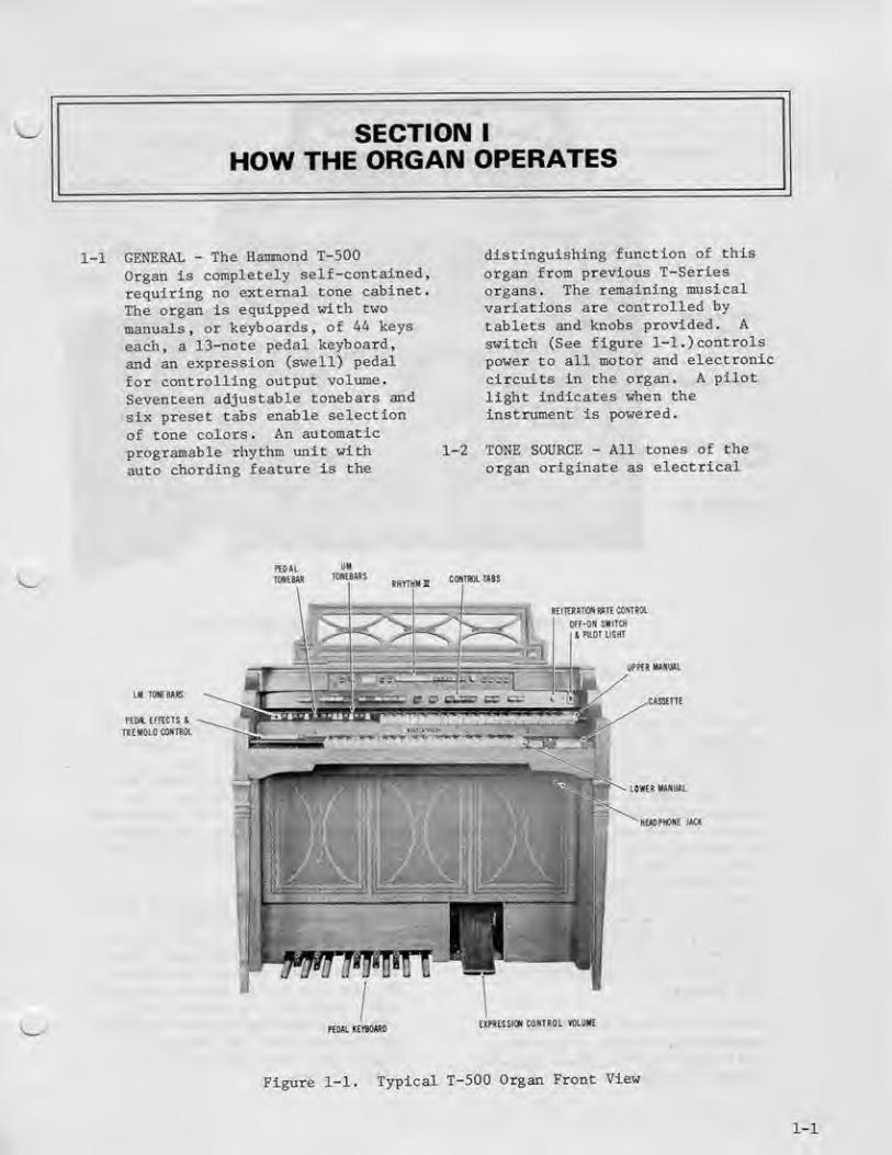
1-1 GENERAL - The Hammond T-500
Organ J-s completely self-contained,
requiring no external tone cabinet.
The organ is equipped with two
manuals, or keyboards^ of ^A keys
each, a 13-note pedal keyboard,
and an eKpression (swell) pedal
Eor controlling output volume.
Seventeen adjustable tonebara and
six preset tabs enable selection
of tone colors. An automatic
programable rhythm unit with
auto chording feature is the
1-2
diatinsuishing function of this
organ froio previous T-Serieaorgans. The reroainine musicalvariations are controlled by
tablets and knobs provided. A
switch (See figure 1-1 .) controls
power to all motor and electronic
circuits in the organ. A pilot
lighc indicates when theinstrument is powered,
TONE SOURCE - All tones of the
organ originate as electrical
,i(5stf ™ebu^Mfnni cnmiBtwas
inrTfffHTCBWTEHinm
1 PBAl ILEKT
Ul laEBIE
PtH.EFlfCT& b
vmt HULLIL
ciuanE
LOVER UNJJL
ntn lErsihWDEVPHlSSKll CONIROL VHUHt
Figure 1-1. Typical T-500 Organ Front View
I-l
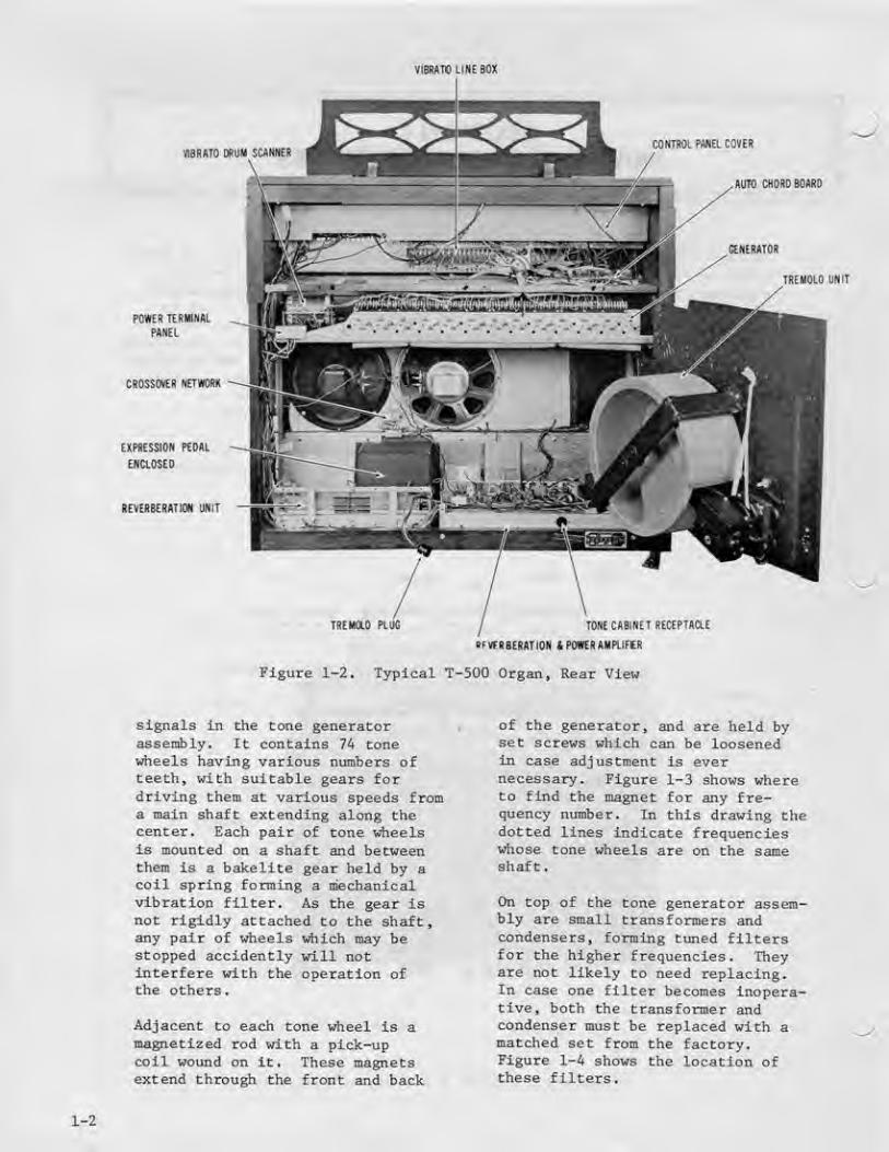
VIBRATO Lirtf BOX
mUTQ DfrUPI IU>HHIR
AUTO CHOAD BOARD
TREMOLi} Uhir
POHIB TERMINAL
PAnEL
CHOSSCrtfi NETWORB
EXPflESSia* PEDAL
ENCtOSED
REVCftBESATICM UNIT
TRtMOO PlUG TONE CABINET ITECEFTAClE
'fVCiS EHAT IG N £ POWa AAI FlIFER
Figure 1-2, Typical T-500 Organ, Rear View
signals In the tone generatorassembly. It contains 74 tone^rfieels having various numbers ofteeth, with suitable gears fordriving them at various speeds froma main shafc extending along thecenter. Each pair of tone wheelsis mounted on a shaft and betweenthem is a bakellte gear held by acoil spring forming a mechanicalvibration filter. As the gear isnot rigidly attached to the shaft,any pair of wheels which may bestopped accldently will notinterfere with the operation ofthe others
.
Adjacent to each tone «heel is amagnetized rod with a pick-upcoll wound on it. These magnetsextend through the front and back
of the generator, and are held byset screws which can be loosenedin case adjustment is evernecessary^ Figure 1-3 shows whereto find the magnet for any fre-quency number. In this drawing thedotted lines indicate frequencies^ose tone wheels are on the sameshaft.
On top of the tone generator assem-bly are small transformers andcondensers, forming tuned filtersfor the higher frequencies. Theyare not likely to need replacing.In case one filter becomes inopera-tive, both the transformer andcondenser must be replaced with amatched set from the factory.Figure 1-^ shows the location ofthese filters.
1-2

'^ '^ \o A@ \e V® \® \& \@ IQ1 issi rSii sSi' «i> et»
§) e^ r^ ^ '^,'1
^ e^ ei e e e e e e e el'P«CHH»4<A tnfpDF UtdPiTVi
" - - '^ @\ @\ @\ ®\ ®\ ^\ ^/iSi }^ t7^ i^l" r^"< ^ ^ /^Ti 1 /^ I 1^ ^ '^"^ f^'l '^ ^
:?) ^ ^63) ^ &n
7DOITID lllUt 1-*M 'fHaCMTia "HOt Ep)C tnOLI JK Q»J Um ^-UTT
Figure 1-3, Magnet Location on Tone Generator
^IVKbl^n aKH iiHIi U'liaSEin * !• t< I* .f Jf It H 1- W *1 n H
l.iXiiiJi.i^*l li -fl -^ t ii it H *i !t ^' ta ii kr r- Bi l' is •• " ii i* ^ 4. n :t ip u [a H ip J> 4 ^^
Figure l-'i. Filter Location and Frequency Termlnatilon on Generator Cover
1-3
The output frequencies of the conegenerator are numbered^ for con-venlence^ in order of increasingfrequency. The lowest^ number IS,is about 87 Hz, and the highest,number 91, Is about 6000 Hz.
The output terminals of thegenerator consist of solder lugsmounted on the back edge of thegenerator- Figure 1-i showsthe terminations by frequencynumber.
PEDAL TONES - The fundamentalpedal tones are derived fromgenerator frequencies nos. 25through 37 by means of dividers
mounted on the Pedal Dividerboard, 124-000178. The derived
frequencies are nos. 1 through
13 for the 16' pitch and 13
through 25 for the 8' pitch.
1-i MAJIUALS - Musical frequencies
from the tone generator go
through the manual cable to
terminal strips on the two
manuals and from them to the
key contact springs.
Each of the two manuals has 44
playing keys, or approximately
3 1/2 octaves. The two manualsdo not cover e^tactly the same
pitch range, but they are
arranged so that the keys oflike pitch are in line.
Middle "C" is the first C on
Che upper manual and the key
1-3


in line with it on the lower
ttsaual.
Under each key are a numbex
of contact springs (foe the
fundamental and harmonics ofChat key) which touch an equalnumber of bus bars when the key
is pressed. (Some keys at the
right end of each manual havefewer springs, as noted in
Fleure 1-5) All contact springs
and bus bars have precious metalcontact surfaces to avoid corros-loo, and the manuals are sealed to
ejcclude dust so far as possible.
In case a contact becomes dirty in
spite of these precautions, a bus
bar shifter is provided in eachmanual to slide the bus barsendwise and thus provide a fresh
contact surface
.
The busbar shifting mechanismfor the lower manual will be
found by looking on the under-side left-hand end of Che
manual. A black wood endblock will be observed.One-haLf inch from the front of
this block is a drilled hole.
Within this drilling is a
^PRINtS
GENERftTORKHEffUEHCT
PEOAL^EYERDARDS
PFll*L
SWITCHED COhNECTOR
Figure 1-6. Pedal Keyboard
1-5

Figure 1-7. Tonebars and Contrcl Tabs (Partial View)
1-5
1-6
small petal tongue with a
puisched hole. Using either
long ngse pliers, or a hook,
this toague can be moved In
and out and It in turn movesChe busbars. The upper manual
shifter 1b in a similar place
but requires removal of the
back to gain access to it.
The key contacts are connected
through resistance wires to the
manual terminal strips- The
manual wiring chart, Figure 1-5
shows how the contacts of each
key are connected to the proper
frequencies to supply fhe
fundamental and harmonics of
that particular key. The blankspaces indicate that no key
contact is used, inasmuch as
the highest harmonics of the
highest keys are above the range
of the tone generator and are not
required.
The busbars of each manual, each
one carrying a certain harmonic,
are fed to bus amplifiers, then
to the harmonic tonebars for that
manual
>
PEDAL KEYBOARD - The 13 playing
pedals are operated by the left
1-6
foot. Like the manuals* they
have light and dark keys
arranged in the standard octavepattern. Figure 1-6 identifiesthe pedals and shows the
generator frequency numberassociated with each. A pedalcontact on each pedal closes
when a pedal is pressed,
allowing the correct generatorfrequency to reach the pedaltonebar amplifier. As the
pedal switches are in a series
arrangement, only one pedal
plays at a time. If two pedalsare pressed* only the lower
pedal will speak. When the
pedal Is released, the lastplayed pedal note continues to
sound for a length of time,determined by the position of
the PEDAL SUSTAIN and PEDALLEGATO tabs.
HARMOMIC TONEBARS - The left
group of 7 harmonic tonebars
(Figure 1-7) is associatedwith the lower manual, andthe right group of 9 tonebars
controls the upper manual. By
sliding these tonebars in and
out, the organist is able to
miK the fundamental and
harmonics (or overtones) in

various proportions- Thedistance a bar Is pulled out
determines the strength of thecorresponding hamonic; and ifa tonebar is set all the uay In,the harraontc it representsis not present in the mixture.Neither manual will playunless at least one of itsronebars is pulled out partof the way, with theTONEBARE tab pressed, or apreset tab Is pressed.
The conebars slide over9 busbars, representingintensity levels, and eachtonebar "has two contactsconnected together by a
5600 ohm resistor. As thetonebar moves, at least oneof the contacts is touchingsome busbar at all tinies» andtherefore there is no "deadspot" in the tonebar motion.The 5600 ohm resistor avoidsfin actual sho^t circuit betweenadjacent busbars.
These busbars extend the lengthof the tonebar assembly but aresplit in the mtddle to form twogroups of 9 (see Figure 5-1.)
Those in the left group,under the lower manual tonebarsare connected to the base of thetransistor Q-351. Those on Cheright group, under the uppermanual tonebars, are connectedto the base of transistor Q-85^through the upper manual TONEBAR& PERCUSSION tablet.
1-7 PEDAL TONEBAR - The centertonebar adjust the volume of thepedals by sliding over 9 busbarsmechanically segregated from theupper and lower manual busbars.The output from this busbar isfed in parallel with thesignal from the lower manual to
the base of transistor q-S51,
1-a EXPRESSION PEDAL - The "express-ion" pedal, sometimes called"swell" pedal (Figure 1-1), isoperated by the player's rightfoot and varies the volume of
both manuals and pedals together
When the pedal is tilted back(closed) by pushing on theplayer^s heel, the music is
softest, and when pushedforward (opened) by the player'stoe, the music is loudest.
1-9 CONTROL TABS - There are 23 tabsOQ tlie T-5O0 series Instrument,each providing some change inthe instrument's operation.
To have the instrument soundafter turning it on, tabs suchas THEATER BRASS and ENSEMBLEwill place the upper and lowermanuals in operation. A tabis in use when in the downposition. Functions of thevarious tabs from left tft right,as they appear on the Instru-ment, are given in the followingparagraphs
.
1-10 PRESET TABS - Two preset tabsate provided for the lowermanual; namely, TONEEAES andENSEMBLE. Four preset tabs areprovided for the upper manual;namely, TONEBARE and PERCUSSION,STRINGS S', FULL TIBIAS 16',THEATER BRASS 16'
.
1-11 PERCUSSION CONTROL TABS - Thereare 7 tabs lAich control percus-sion. These operate in eitherthe up or down position ofthe upper manual TONEBARS fi
PERCUSSION tab. When theTONEBARS & PERCUSSION tab Isup, percussion only is playedon the upper manual; when thetab is down, tonebar effects andpercussion are playedsimultaneously. For tonebar
1-7

effects alone on the uppermanual^ Che seven percussiontabs must be in up posttton,and the TONEBAES & PERCUSS ICWCah muac be down.
1-12 VIBRATO TABS - The T-Seriesinstruments are equipped withfour Vibrato tabs to vary the
Vibrato effect . An additionaltab (VIBRATO ON) to the left
of Che vibrato group permitsthe vibrato effect to be
introduced inimediately.
Various vibrato effects are
available by use of the Cabs>Vibrato Celeste III la
achieved by depressing bothVIBRATO CELESTE I AND II Cabs.
1-13 REVERBERATION - Three degreesof reverberation are obtainedby the use of either or bothtabs labeled REVERB I and
REVERB II. These tabs. In
addition to Cuming this
feature on, govern the loudness
or amount o£ reverberation.
1-H VOLUME SOFT, BRILLIANCE TAB,AND REITERATION RATE CONTROLThe VOLUME SOFT tab controlsthe overall volume of theorgan and Is useful uhenplaying might disturb others.
The BRILLIANCE tab in the upposition bypasses a portion of
the higher frequencies toground, making the organ sounddeeper.
The REITERATION RATE control,as the name Implies, adjusts
the rate or speed of reitera-clon when used in conjunctionuith the percussion tabs aadreiterate cab.
1^15 ?£DAL ROCKER TABS, LOWER LEFTEND BLOCK - Upon playing the
bass pedals, a normal decayand attack axe heard when the
pedal tonebar is pulled out.Either IS' or 3' pitch ia
available by means of the
PEDAL a'/l&' cablet.
Use of the PEDAL LEGATOtablet provides a very slowpedal decay which many beginnersfind useful, as the pedal lastplayed sounds until the next oneIs played, PEDAL SUSTAINcauses the pedal tone to decayslowly. PEDAL MUTE givesadded deep tone to the pedalswhen desired. Further In-formation concerningelectrical function Is givenIn paragraph 2-5.
1-16 TREMOLO ROCKER TABS, lowerLEFT EHD BLOCK The TREMOLOON/OFF Cab connects theorgan signal to the Tremolospeakers when "on". TheTREMOLO SLOW/FAST tab controlsthe speed of the Tremolo, whichruns whenever the organ is "on".
1-17 AUTO CHORD BOARD (12i-000179)The Auto Chord Board containsthe gating circuits for lower
,manual and Hi/Low Bass of thepedals. This board is notindependent functioning as itneeds keying or gating pulsesfrom the Rhythm III unit.The different auto chord modesare selected by the Rhythm IIIswitching circuitry.
If the Auto Chord Board isremoved the pedal and lowermanual voicing is silenced
.
1-lB CASSETTE 121-000139 & 121-000165This unit is 1/3 trackmonaural cassette transportdeck.. It features controlledelectronic speed regulationand automatic level control
1-3

mtnizing distorted record-ings, A microphone is
Included.
The operational features are
as follows
:
A. Keyboard type transport
contiol for Stop» Rewind^Fast Forward S Play/Record functions
.
B. Thumb wheel type playbacklevel adjustment. (Non-
functional in record mode)C. Electromechanical accidental
erasure-prevention systemkeyed with Eecord/Playcontrols and rear knock-outtabs on cassette cartridge.
D. External access jack for
Microphone. The microphonehas a motor start-stopswitch and when plugged in,
disconnects the "Aux." Input.
E. Lid loading cassette.F. Thumb wheel type speed
control adjustment with red
mark on knob denoting centerposition. This red markallows rapid return to
standard cassette speed,G. In the record mode of opera-
tlon^ output signal must bedisconnected from outputterminals
1-19 RHYTHM III - The inbuiltautomatic Rhythm III is con-tained in one assembly 125-
000082. This rhythm unit is
a step-up version of Khythm 11-Acontaining such features as
Auto-Accompaniment output
signals, Touch-Start, FootSwitch Preset capability, andfour play-a-long voices. Allplayer-operated controls are
mounted on the Inbuilt RhythmUnit. The following describesthe function of the controls.
A. PROt^LAMMED PUSH BUITOHS,There are 15 interlockingpush buttons mounted onthe control panel to
select different rhythm
patterns. Two or ffiore
rhythm patterns may be
played simultaneouslyif desitedj including3/4 and 4/4 time rhythmpatterns
.
Bi SILENT/SOUND - The Silent/Sound tablet is used to
silence the audio output
fat the automatic rhythmvoices (but not thefollow-the-player voices)
and reset the timinggenerator when it is movedto the Sound position.
C. CONTINUOUS/TOUCH START -
The Continuous /TouchStart switch allows the
player to start therhythm unit from eitherthe lower manuals or pedalsby first placing this
tablet in the Touch Startposition, second, movethe Silent /Sound rocker
switch to its Soundposition, and then depresseither a lower manual or
pedal key
.
D. FOOT SWITCH RESET - TheFoot Switch Reset tabletallows the player toeither just silence the
audio output (IncludingChe follow-the-piayervoices) when the foodswitch is depressed or,
lAen the Foot Switchreset position, toalso reset the generatorwhen the foot switch Isreleased.
E. AlJrO ACCOMPANIHENT -
The Auto Accompanimentsuitch when placed in the"on" position, providesgating signals for thelower manual and for highand low pedal gates. If
the Foot Switch Reset is
in the "off" position,the foot switch does not
1-9
aiiect Auto Accompaniment.If Che Foot Switch Reset is
In the "on" position, the
foot swicch silences Che
Iou?r manual and pedals,because the pulsing cracksare not available Co
operate the 3 gates.Turning "on" the AutoAccoinpaniment swi C ch
disables Che Pedal SustainTab and the Pedal l6Va' Tab.
F. TEMPO LAMP - The Tempo Lampblinks beats (4 beats per
Dteasure) when the rhythmunlc is silent and blinksnteaaures «hen the rhythmunlc Is "on". If the FootSwiCch Reset is in che "off"posiclon, Che £oot switchdoes not affect Che blinkinglamp. If Che Foot SwitchReset is in the "on" posicionthe foot switch operationcauses Che lamp Co blink atche beat race.
G. TEMPO CONTROL - The tempoknob concrols che rate ofthe rhyChm unit from 48 Co300 beats per minute. Thecempo knob also has a LampOff posicion to turn offthe Tempo Lamp when cherhyChm unit is not in use.
U. VOLUME CONTROL - TheVolume Control is a dualcontral which varies theoutput level of both thehigh frequency and the lowfrequency output channelssimulCaneously
.
I. BASS DRUM & CYMBAL - TheBass Drum and CymbalCablecs allow the player to
activate these voices bydepressing a pedal key onche organ. These voices arecontrolled by che volume andcan be silenced by theexpression pedal kick switch.
1-10

^^
SAFETY NOTICE
Gr«ii care Jiaa »eri lehen Jn irts deAiQn ana TiAru'ftciure oi rhig prodiM;! id anura inai no
Bfioch Fiozarfl BkljlH iHi arty a'poHd rrktlal cam. internal ssrvKa Dpareriani cin «ipo3a II10
lacTiniGJan in rtaiaiOoui Lfna vDiiagn irid Kcidgr>iaiiy cbum inaH vaitagn lo aaoev on
uposaa matai pvisdurJriQrfipdirtM-raBEBambiyai proaudcoTicwnanii. To preveni ihia. wofh
n ih«e prwiLicts irtc^uid oniY » pfirTmrnad Dy rhue wj^d an iFLcrouDhiy lomiiiHT Miin ir>«
pracBulluiia noHuary fhan naii<\nQ on in Is lyp« ol ^guLpmBn.
To proiocr ihouior, it li rtquirvd ihai ill rtcraaurt parii ind Mftiy Inivriocti bi rHinrwi uthvir criglnil condU^vn *vf FIm iDllafrlng iHtk b« p«rlarm*d balort rtlurnlnfl lli« piodLKE Id
tfM Qianar akiranr •rrl» Dfi4raTlD(l.
Pliil] ihft AC Ilr4 cord dlfoclly Into P iJia voliaae AC roceptacJe |do nol uh ar> miallon
Tramlormsf lor ihia fMi] and lurn H>fl prMud on, Cormoci ifiB HBiirfirK (aa an&*n belo") In
serieiwiriiart H»poMdmaiBipArt9irid«hrio»rieariharaunaaucnasa waitrplpoor cunduJI-
Uaaan AC VOM ol S.om onms p«i voltoi hiaheraanHlilvll, to rnusure IM^ voU^ge ijrapacaaa
TtM nfllworK. Uove 1^ noiwork connBcilan To Mcn a^pMO-J moial pan imaFal tHaaaps, icraw
hea^s, Knoos and conifoi aha'iB. aacurcnson, erc.i una rneaaura iha vniiag* flrop acrou tno
noiwurk RavorM iris Una pikio and rop»t ifvB rnHaHuramenla An, rewlng 0' * woUa HW5 or
mora la aicauive and indicaiH puiemiHi artock nutrd wnich musi ub cwracEoa bafora
nlufnlng Uie proiJucl lolEie uui
CVmFCTtD TO #DnEl FTTH ERDUHfl
Tfl [JPDSEl iEUL fl.»TS

SECTION II
THEORY OF OPERATION
M*tihtT "^St^^
VI0H4TQ SHALL TABLET"'
e:T.^B^
iO-liOlS Of VIBJ9A10 LINE
OUTPUT
IP4PUT
V3BHATO
OtOAA'
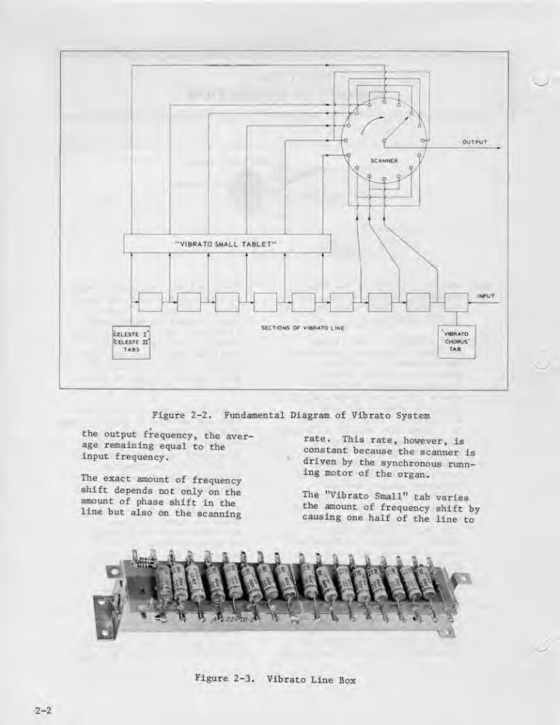
Figure 2-2. FmidaJnental Diagram of Vibrato System
the output frequency » the aver-age remaining equal to Cheinput frequency.
The exact amount of frequencyshift depends not only on theamount of phase shift in theline but also on the scanning
rate. This race, however, laconstant because the scanner isdriven by the synchronous runn-ing motor of the organ.
The 'Vibrato Small" tab variesthe amount of frequency shift bycausing one half of the line Co
Figure 2-3. Vibrato Line Box
2-2
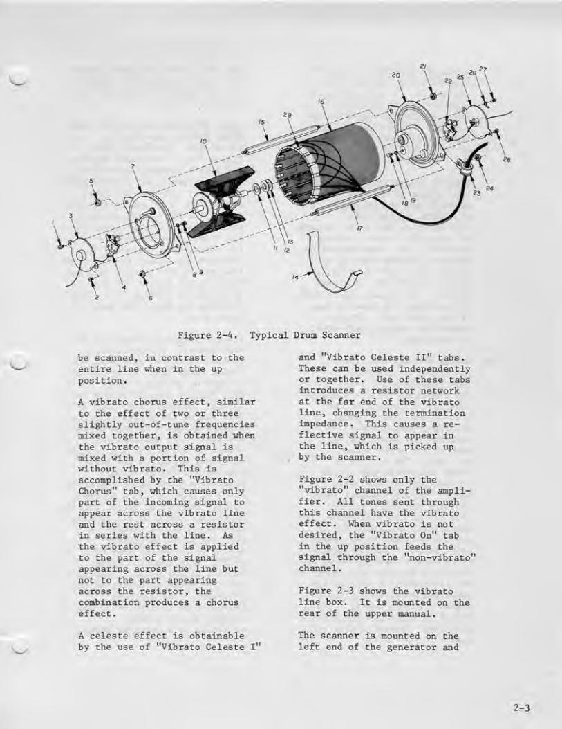
Figure 2-4, Typical Drum Scannei:
be scanned, in contrast to theentire line when In the up
position
.
A vibrato chorus effect, similarto the effect of ti*io or threeslightly out-of-tune frequenciesmixed together, is obtained whenthe vibrato output signal is
mixed with a portion of signalwithout vibrato. This is
accomplished by the "VibratoChorus" tab, which causes onlypart of the incoming signal to
appear across the vibrato lineand the rest across a resistorla aeries with the line. Asthe vibrato effect is appliedto the pa.rt of the signalappearing across the line but
not to the part appearingacross the resistor, thecombinaticn producer a choruseffect.
and "Vibrato Celeste II" tabs.These can be used Independentlyor together. Use of these tabsintroduces a resistor networkat the far end of the vibratollne» changing the terminationimpedance. This causes a re-^
flective signal to appear inthe line, which Is picked up
, by the scanner.
Figure 2-2 shows only the"vibrato" channel of the ampli-fier. All tones sent throughthis channel have the vibratoeffect. When vibrato is notdesired, the "Vibrato On" tabin the up position feeds thesignal through the "non-vibrato'channel
.
Figure 2-3 shows the vibratoline box. It is mounted on therear of the upper manual.
A celeste effect Is obtainableby the use of "Vibrato Celeste I"
The scanner Is mounted on theleft end of the generator and
2-3
is driven directly via an "O"
ring from Che tone generatorClin motor. It is a raultl-pole
variable capacitor with 16
equal stationary aegmenta and
a rotor. Connection to the
segments are made by 16 snap-
on contacts ^ Figure 2-i shows
the construction of the scanner.
Signals coming from the vibratoline appear on the stationarysegments and are picked up, oneat a time, by the rotor.
Connection to Che rotor is madeby graphite brushes as shownin Figure 2-4. When assembled,graphite brushes iniEt be no
closer Chan 1/16" from outerend of contact pin or brasssleeve. Adjustment may be made^if necessary, by bending legsof the brush lug. Brushesshould not concacc each otherIn operation.
2-4 MANUAL BUS BAR AMFLIFTEES^124-000015 S 124-000016(See figures 5-3 & 5-4)
The busbar amplifiers for bothmanuals are located to therear of the control panel.
The lower tnanual boardcontains one amplifier foreach of the seven harmonicbus bars. The outputs of
these amplifiers are routedto the tonebars and voicemesh. The upper manual boardcontains one amplifier foreach of the nine harmonics.
Amplified signals are fed to
Che tonebars and three presetvoice meshes. All the ampli-
fiers have a response curve de-signed to decrease the amount ofkey transient- A typical bus
amplifier receives its inputsignal from the busbar. Thesignal is amplified and sent tothe proper tonebar and/or voicemesh.
The voice mesh mentioned selectsthe proper concent and ampllcudeof each harmonic necessary for aparticular voice.
2-5 PEDAL KEYBOARD AND SWITCH, FEDALKEYER BOARDS, 124-000025.124-000026, 124-000027 (SeeFigure 5-6) - The pedal keyboardand switch assembly is locatedunder the power and reverberationamplifier. Three pedal keyerboards. No. I, 2 and 3, are alsomounted on Che switch assembly.Board 1 contains the keyers forthe five lowest pedal notes(25 through 29). Board 2
contains Che keyers for the pedalfrequencies #30 through ff33 , andBoard 3, the keyers for fre-quencies #34 throu^ tf37. Thisprovides one keyer for eachpedal note
.
All pedal keyers operate In thesame manner. Following is a
typical function, involving thelowest pedal (C) . Switch S-751is closed, placing +15V on C-751.This voltage forward biases Q-753through resistors E-756 and B-757.This allows the generator signal,present at pin 6 to pass to theeoimltter. All emitters arecommon on the boards and provide
' the input signal to the highpass active filter networklocated on pedal keyer board ff3.
Board rfl also contains an erasecircuit and buffer stage, workingIn conjunction with all pedals.Whan any pedal is pressed, a
negative pulse is coupledacross C-750 to the base ofq-750. This negative pulsereverse biases Q-750, causing apositive pulse to appear at thecollector. The positivepulse passes through D-750 andforward biases Q-75]
,
resulting in a negative going
2-4

pulse to ground at the base ofQ-752 and the cathodes o£ pedaldiodes D-751 through D-763,This is the erase pulse and
turns off any pedal keyer whichdoes not have its associatedpedal pressed. The buffer stageQ-752 transfers the positive DCsignal from the keyer and the
erase pulse to other organfunctions at pin 8.
2-6 PEDAL DIVIDER & FILTER BOARD
ASSEMBLY. 12^--00017& (See Figure5-7) - The Pedal Divider and
Filter Board Assembly is locatedon the power and reverberationamplifier diassls. It providesaiDplificaCion, shaping anddivision by four bistablefrequency dividers.
The amplifier and shapingcircuit receives its inputsignals from the pedal keyercircuitry- The signal Is
amplified by Q-70i, q-702 andQ-703. Shaping is accomplishedby q-70A and Q-705, uhichfurnishes a +12V square wave at
the Input frequency to the firstdivider bi-scable, Q-706 andQ-707 make up the first bi-stableor flip-flop configuration . TheInput slgna] is divided by 2 andappears at the collector ofq-707. This signal will becomethe 8* component of the pedalsignal uhen called for by thepositive DC signal from the
Auto Chord hoard. The DC signalforvard biases D-702 whichallows the signal to passto output pin ffl2. The signalat the collector of Q-707 alsobecomes the input to the
second bistable.
(J-70& and Q-709 make up the
second divider. The signal Is
again divided by 2, and willappear at the collector ofQ-709. This signal will
becomecalledsignalboard
.
biasessignal
the 16' component whenfor by the positive DC
from the Auto ChordThe DC signal forward
D-701 which allows the
to pass to output pin
2-7 RECOVERY AND fJON-VlBRATO
BOARD, 12^-000014 (See
Figure 5-A) - The recoveryand non-vibrato board is
located on the control paneland consists of two recoveryamplifiers. One recoveryamplifier handles the
sigjials from the pedaltonebar, lower manualtonebars and presets. Theother handles the signalsfrom the upper manual tone-bars, and presets. Theboard also contains thenon-vibrato amplifier andintermediate amplifier(with click filter) whichdrives t:he main amplifier.
The recovery amplifierreceives its signal frominput pins 6 or 8. Thesignal is amplified byQ-851 or Q-852. and theoutputs appear at pins 5
and 7. These outputs aretied together and sent to
the "Vibrato On" tabletlocated on the controlpanelf where the "Vibratoor Won-Vibrato" mode willbe determined.
With the "Vibrato On"switch in the Off positionthe pedal and both manualsignals appear at pin A,
The signal is amplified byq-e53 and sent to theintermediate ampllferand click filter.
The Intennediate ampll-
2-5
fler receives iC3 signalfrom pin 9 in the vibratomode or from R-S60 in the
non-vibrato mode. It Is
amplified by q-354.
The remai-nde r of
the circuitry acts as aclick filter with the
output appearing at pin 3.
The output of the entireboard is controlled by
potentiometer R.-S70
that also serves as"system" volumeadjuatraent
.
2-8 Vl&EATO BOARD ASSEMBLY,124-000018 (See Figure5-6) - The vibrato boardassembly Is alao locatedon the control panel.It controls the vibratodrive and vibratorecovery amplifiers.
The vibrato drive ampli-
fier receives its signalat pin 1 from the "VibratoOn" switch. This signal
is amplified by a lownoise transistor Q-SOl,followed by furtheramplification by Q-802,and q-803 (the latter anemitter follower). Finalamplification is by q-804and transformer T-801.Output to the phase shiftis from pin 4.
The vibrato recoverycircuit receives its
input signal at pin 3
from the vibrato scanner-
The emitter follows Q-e05
,
Q-806 and Q-807, present
3 high reactive impedanceto the scanner with theoutput appearing on pin 7.
2-9 SWELL PEDAL CIRCUITRY -
The main organ signalinput to the Rower Ampli-fier board (124-000017)is at pin S. Pin 10 of the
board is connected to the
LDR located on the SwellPedal assembly (133-000004).The LDR provides a varia-ble resistance to groundto vary the amplitude ofthe input signal.
2-LO POWER AND REVERBERATION AMPLI-FIER ASSEMBLY - The power andreverberation amplifier assem-bly is DKiunted on the pedalkeyboard and switch assembly-It contains the power supplies
»
the swell pedal circuitry, themain amplifier, the reverbera-tion drive and recovery, andthe previously mentioned pedaldivider and filter boardassembly.
MAIN AMPLIFIER, 124-000176(See Figure 5-8) - The result-ing signal at C-601 is amplifiedby Q-601 passed to the base ofQ-602. The signal is thenamplified by Q-602 and transferredto the primary of T-601 tbrougb theDarlington configuration emitterfollower Q-603 and q-604. q-605and Q-606 Is an "AB" typeamplifier and the output to thespeakers appears on pin 19.
REVERBERATIOT DRIVE Thereverberation drive gets its
3-6

signal from the emitter of Q-601.
The signal is amplified by Q-607and Q-608 and transferred to the
primary of T-602 , Q-609 andQ-610 is an "AE" type amplifierand the output appears at pin 2&,
REVERBERATION KECOVERY. Theoutput from the reverberationunit appears on pin 4, Thesignal is amplified by Q-611and Q-612 and appears at pin 6.
The reverberacton signal thengoes through the reverberationtab circuitry and appears as aninput at pin 12
.
2-11 POWER SUPPLY CIRCUIT - Powersupply components are located inChe power supply chassis assem-bly (127-000176 thru -000178).All necessary DC supply voltagesfor the rhythm jnit are suppliedby this chassis. The voltagesare +15V DC, +1SV DC, +23V DC,+25V DC and -25U DC. 120V AC
50/60 Ha is supplied to the
power transformer from anexternal source. The secondaryAC voltage Is 27V RMS,
D601 & D602 rectify thesecondary voltage C615 filtersit and -25V DC appear at theoucpuc of this circuit.
D603 & D604 rectify the second-ary voltage C6i6, R644 filter+25V DC. 15V zener D608, R645,f- C117 regulate and filter the+15V DC supply,
D605 & D606 rectify the second-ary voltage and the combinationof C618, L601, C619A, R643, andC619B filter the supply voltagesof +25V DC, +23V DC, and+18V DC,
2-12 PHONE JACK - T-500 organs areequipped with an earphonejack, which will give pleasingresults. Use headsets suchas Clark 200, Koss 3P-3XC, orSharp HA-10 , When earphonesare plugged in speakers aredisconnected for listeningprivacy. Tremolo effects arenot heard in earphones.
2-13 SPECIAL POWER SOURCES - T-500organs are made to operate onthe voltage and frequencyspecified on the nameplate.They are available for
117V/60 cycle - 117V/50cycle - 23iV/50 cycle and234V/60 cycle. If theunit is moved to anarea having voltages orfrequencies other than thosespecified on the nameplate,consult your local dealerconcerning changes requiredfoe conversion.
2-14 PERCUSSION BOARD ASSEMBLY(124-000170) - The follow-ing inter-related circuitsare located on this board(See Figure 5-10)
:
1. 1 1/i Harmonic Generator2. Normal Percussion Keying3. Reiteration Keying and
Triggering4. Main and Alternate
Channel Gates
A. 1 1/4 HARMONIC GENERATORThe output of this circuitis used only aa part of thechimes voice.
The circuit receives itsinput at pin 11 from the
2-7

upper manual 5ch hacmonicbuss amplifier. The signalis amplified by Q514, Q515and q5l6. The resultantsquare wave output providesthe Input to IC501, IC501is a *J-K Flip Flop integra-ted circuit. The collectorsupply voltage for the ICand Q51fc Is a result of theaction of D12, a 5 voleZener diode
-
The output from 1C501, pin 8
±3 coupled to a uaveshapingnetwork and to the outputpin 14.
*J-K Flip Flop - IC 510 is asingle package two stage bi-stable divider. Failure ofone stage requires thereplacment of the IC package.Several pins of the IC pack-age are not used in thiscircuit application.
B. NOKMAL PERCUSSION KEYING -
In the fionnal percussionmode, when a key is depressedon the upper manual, 220Kohms of resistance areconnected between pin 15 andground. As a result, the
positive voltage at pin 15is reduced. This negativechange is differentiated byC517 and applied to thebase of Q512 (normally on).The resulting positive pulseat Q512 collector Is coupledto Q513, turning it on. Thenegative change, at thecollector of Q513, is coupledby C510, forward biasing D509and D510. C511 is alsocharged. Since the pulse usedto charge C511 is momentary,C511 begins to dischargeimmediately
.
With the Guitar and Chimeaswitch in the off position^pin 10 is grounded- Thedischarge path of C511 is
split. One path is throughD510, R537, and the combina-tion of Q510 and q5ll. Theother is through D511 andR5i6 to ground. This pro-vides for the short decaytime. When either theChimes or Guitar switch isdepressed, the ground isremoved from pin 10 and thesecond discharge path isopened. The result is a
longer decay tlrue.
The entire action will berekeyed when an additionalkey Is depressed. The voltageat the input will drop in
increments with each key de-pressed and result in anoutput pulse fed Co Q5i0 andQ511. This type of keyingis referred to as Legatotype percussion,
REITERATIOM KEYING ANDTRIGGEEIWG - When Chereiteration tab is depressed,the percussion keying busbarin the upper mariuaJ is con-nected to pin 2. Withnormal percussion, it wasconnected to pin 15,
When an upper manual key isdepressed, a 220K resistorconnects pin 2 to ground.This causes the base oftransistor Q501 (normallyoff) to drop from +23 voltsto approximately +22,5 voltswhich causes it to conduct.The collector of Q501 risesto +23 volts. The +23 voltsis routed to pin 4, whichis connected to the reiter-
2-e

D.
atlon rate control on the
control panel, and also to
the top of R506.
Froin Pin 4» through to the
wiper of the telteration
coi>trol, which is connectedto pin 18, Che voltage is
fed to R508 and R509. Thevarying voltage applied to
pin 18 causes the astablemultivibrator (Q506 and
(J507> to vary tn frequency.
The positive 23 volts applied
CO E506 causes D502 to be
forward biased. This action
brings the junction of R506
and D502 to a positive 15
volt level. This 15 voltscauses D503 to be forward
biased and subsequentlybecomes the supply voltage.
The outputs are taken alter-
nately from the bases of the
multivibrator transistors.
The negative pulses driveChe main and alternate gate
circuits.
MAIH Am ALTERNATE CHANNEL
GATES - The main channel
gate circuit consists of
transistors Q50e, Q509 , Q510,Q311.
As Q506 and q507 (MulCi-vibrator transistors) con-
duct alternately »pulses
from Che base of Q507 are
supplied to the emitter of
Q511, the gating transistor^
and Q510, a grounded baseamplifier. The AC signal
on the base of Q511 is
Insufficient for qSll to
conducts The pulses from
the base of Q507 supplysufficient bias co causeconduction of Q511,
Through Q511, two signalpaths exist, one for thegating signal and one for
the music signal. Theusable portion of the musicsignal passes through the
base collector junction of
q5ll, through R556 (MainNull Control), to the baseof Q509 . The music signalis amplified by Q509 andcontrolled as to amountof output by the settingof R557 (Percussion LevelControl).
The gating signal, as wasmentioned previously, is
applied to the emittersof qSlO and Q511. Thesignal which goes through
Q511 appears at the col-lector with the musicsignal and is applied to
the base of Q509 . The
gating signal alsoappears aC the collectorof q510 and is directlycoupled to the base ofq503. From the emitterof qSOS, the signal is
coupled to the emitterof Q509. The signal fromthe emitter of Q509 appearsat the collector out ofphase with the signalimpressed on its base.As a result, the twogating signals are out
of phase and cancella-tion takes place- TheMain Null Control (R556)
Is to affect maximumcancellation of the gatingpulses.
2-9

The operation of the
alternate channel gate is
identical as that descri-bed for Che main channel.
Of special note is that R557(Percussion Level Control)is the oommon collector loadfor both Q502 and Q509. As
a result, the gain of bothgates Is controlled by R557.
E. PERCUSSION SETLC? PfiDCEDURE
Equipment Needed:
1, Tektronics Oscilloscope503 or equivalent.
Depress the "REITERATE" tab
and set Reiterate Rate controlat approximately mid poaltioo.
Depress and hold key tf25.
Rotate the Percussion controlR557 full counter clockwise
(up) . Refer to Figure 5-10 forfolloulng setup procedure.
Connect the oscilloscope to the
junction of C503 and fi527 onPercussion Board, Set theoscilloscope sensitivity to
10 [nv/cm and rotate the
Alternate Null R519 and MainHull R556 controls until thepulses on the oscilloscopeare adjusted to minimuia
amplitude. Observe Figure2-5 for proper waveshape.
4KOT flCCtPTflBLE
i-
ACCEPTaeiE
PERCUSSION AND REITERATION GAINDepress "CELESTA" tab, depress
"REITERATE" tab and place con-trol In approximate lald positionConnect the oscilloscope to the
speaker terminal and adjustvertical sensitivity to1.0 V/cm. Depress end holdupper manual key fl25.
Adjust the Percussion Levelcontrol (R557) until the
percussion output is 10. 5U
+ .3V Peak to Peak.
Return all tabs to their "off"position. Depress CHI^TES orGUITAR tab. Depress Key tf25
.
And hold. Decay time shouldbe approximately threeseconds. All other percussionvoices should have a decaytime of approximately one-halfto one second.
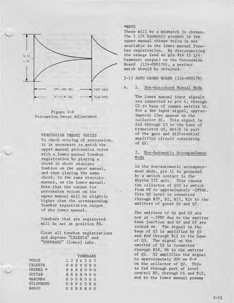
REITERATE RATE ADJUSTMEHTDepress CELESTA and REITERATEtabs. Adjust the ReiterateRate control to maximum {full
clockwise). Hold down uppermanual key fl25 and measurethe duration of one completepercussion wave form on
oscilloscope. It should bebetween 45 and 65 milli-seconds (Figure 2-6). Resetthe oscilloscope.
Horizontal Sweep .1 sec/cni.
Adjust the Reiteration Ratecontrol to minimum (fullcounter-clockwise) . Hold downupper manual key fr25 and
measure the duration of onecomplete percussion waveformon the oscilloscope. Itshould be between .10 and .45
seconds. Turn off REITERATIONtab,
h-tmi flccEPToeiE
2-10
Figure 2-5
Percussion Null Adjustment
'^^
SLOU RATE
Figure 2-6
Percussion Decay AdjustmenC
PERCUSSION PRESET VOICESTo check voicing of percussion,it Is necessary to match theupper loanual percussion voicewith a lower manual Tonebarregistration by playing achord in shore staccatofashion on the upper manual^and then playiag the samechord, in the same staccatomanner, on the lower manual.Note that the output forpercussion voices on theupper manual will be slightlyhigher than the correspondingTonebar registration outputof the lower maniial.
Tonebars that are registeredwill be set at position flS.
Clear all tonebar regist rationsand depress "CELESTA" and"TOHEBARS" (lower) tabs.
VOICECELESTECHIMES *
GUITARMARIMBAXYLOPHOHEBANJO
TOHEEAHS12 3 4 5 6 7
8
8 8 8
3 8 8 8
8 8
8 S
8 S 8 8 8
*NOTEThere will be a mismatch In chimes.The 1 1/4 harmonic present in theupper Dianual chimes voice is notavailable in the lower manual Tone-bar registration. Ey disconnectingthe orange lead at pin ffl4 (1 1/4haimonic output) on the PercussionBoard (12A-000170), a perfectmatch should be obtained.
2-15 AUTO CHORD BOAED (124-000179)
A. 1. Non-Autochord Manual Mode
The lower manual input signalsare connected to pin 4, throughC? to base of common emitter Ql.For a 5inv input signal* approx-imately X5niv appear on thecollector Ql. This signal isfed through C3 to the base oftransistor Q5, which is partof the gate and differentialamplifier circuit consistingof Q2.
2. HOn-Automatic AccompanimentMode
In the non-automat ic accoropani--
ment Diode, pin 11 is groundedby a switch contact in theRhythm III unit. This causesthe collector of QIO to switchfrom OV to approMimately -19VDC.This DC level is connectedthrough R37, D2, RIS, RU to theemitters of gates Q4 and Q5-
The emitters £ Q4 and Q5 arenow at --5VDC due to the emitterbase junction and Q4 and Q5 areturned on. The signal on thebase of Q5 is amplified by Q5and fed through Rll to the baseof q3. The signal on theemitter of Q3 is connectedthrough R18, R6 to the emitterof Q2. Q2 aniplifies the signalto approximately ?00 mv P-Pon Che collector of Q2. Thisis fed through part of levelcontrol R5, through C4 and R12,and to the lower manual preamp
2-11

B.
in Che organ- Lower manuallevel is adjusted by R5.
Autoniatle AccompanimentHode
In the automatic accompani-ment mode, pic II is notconnected to ground in the
Rhythm III unit. Theappropriate track, differ-
entiated ouCput is connectedto pin 7 of the Autochofd PUB.
This is approximately 1 ms
wide -5V P-P spike, which is
connected through £24 to the
base of q?.
When Che player depresses alower manual key, pin 9
becomes connected to groundthrough a 220K resistor.The -20VDC at pin 9 risesapproximately 2V. Thischanges the bias of Q8 and
its collector switches from
OV to -20VDC, The -20VDCis connected through K23 to
the collectoc of Q7, whichallows the repetitive spikeon the base of Q7 to appearon its emitter. Q7 acts as
an emitter follower each timea key is depressed. Thenegative spike is fed through
R21, D3 Co Che base of pulseamplifier Q6. The positive
going spike at Che collector
of Q6 ia fed through C6,
integrated by R15 and C5 andthe resulting negative pulseis fed Through R14 to theemitters of gates Q4 and Q5,
Since Che input signal from
the manual Is at the baseof Q5 (as described in uon-automacic accompaniroenc mode),
the amplified signal onceagain appears at the output
pin 6, however , the outputoccurs at the repetitiverate» as determined by the
track signal applied to pin 7.
Since Q2 and q3 are part of
the differential amplifier,
the resulting undesirable DC
change which could occur at
the output can be adjustedCo a minimum, so that onlythe desired audio signal
variation can be seen at theoutput collector of QZ. Also,each time a key is depressedthe resulting DC level change
at pin 9 is fed through CIO
to the base of Q9, which is
a pulse amplifier. Theresulting -20VDC pulse on
the collector of Q8 is fedthrough pin 10 and is usedby Che Rhythm III unit for
the touch response mode and
for legato keying from Chemanual of the Brush and SnareDrum voices-
C. 1. Hpn-AutQ Accompaniment PedalMode
In the non-auto accompaniment^ pedal mode of operation, pin 15
is not grounded by Rhythm 111;and when a pedal is played,approximately +9V is appliedto pin 19, through DIO, R49
and to base of Q16, QI6 is
Cumed off and its collectorswitches to approximately -15V.This signal is fed through R46
Co base of Q15 and turns offQ15. Q15 is used as a ooisegate, and when it turns off
it allows any signal whichappears on its collector to
2-12

be coupled tKrougli C15 to the
base of pedal preamplifier Q20.
When a ptdal Is depressed, the8' and 16' signals are applied
through diodes to pins 21 and
13. The +9V is also connecced
tbroueh R50» D13 co the baseof Q19, This positive voltage
turns on Q19 , and its emitterrises to approxtmatiely +SVDC.This DC level is fed through R59
,
and it provides forward bias for
the diode from the pedal S'
divideri and the 8' pedal signal
is fed through Ii60 and CL5 tothe base of Q20. It should beremembered that Q15 noise gatewas also turned "off" by the
+9VDC, which thus allows the 8'
signal to appear at the base of
Q20.
Q20 is a common emitter amplifier,and its collector output is con-nected back to the pedal pre-amplifier in the organ.
Operation of the 16' pedalcircuit is identical to the
above stated description,except <31i must be turned"on" by bias on diode D7.
This is accomplished by the16/S switch in the organ asit connects pins 15 and 14tog^Cher.
2. Automatic Accompaniment PedalMode
In the automatic accompanimentpedal mode, the 8' and 16'
signals are connected onceagain to pins 21 and 18, but
pin 15 is grounded by a switchcontact In Rhythm 111. Thisremoves the bias from diodes D7
and Iil3 but allows the noisegate transistor Q15 tofunction as previouslydescribed. In this mode a
differentiated track (depend-ing on which pattern is beingplayed) is connected to pin
20, through R52 and to the baseof switch transistor Q17.This produces a +15VDC pulseon the collector of Q17, whichoccurs at the rate of inputtrack pulse. The pulse is DCcoupled by R55 to the base of
Qie, This switches Q13 on-offat the input track rate, andthe resulting to 15 voltpositive pulse is fed throughC13, D12 and R58 to the baseof Q19. QX9 turns "on" and
"off" at the input track rateand this biases the diode iiL
the pedal circuit and allowsthe 8' signal to appear at the
base of amplifier Q20. C13
and R57 determine the "on"time period.
The operation of the 16" pedalcircuit is identical to thatdescribed above except that
Q12, Q13, and qi4 are used.
Each time a pedal is depressedthe resulting -20V pulse oncollector Q16 Is also connectedthrough R51 to the Rhythm III
unit. This is used in the
Touch Dtode of operation andused for pedal keying of Cymbaland Bass Drum Voices-
' The collector of Qll is connec-ted to the sustain circuit of
the console. When operatingRhythm HI in the AutoAccompaniment Mode, Qll is
turned "on" and removes the
15 volts from the sustainingcircuit. This disables the
Pedal Sustain rocker switch.
2-16 CASSETTE 121-000139 & 121-000165
Performance Specifications(Electrical)
A, Record/Play Response:With 70 m v applied to "Auh.
Input", record 50 Hz followedby 6K Hz using Philips TC-R
2-13

D,
cassette and using a 100 ohms
load resistor at playbackoutput^ with volume levelset for 1.0 volt* the 50 He
and the 6K H3 output shall
be within -6 db using IK Hz
as a refecence.
ALC Dynamic Range OutpuC
and Hgrmonic Distortioni
1. Uith 40 mv at 1 K Hz
applied to "Aux. Input" and
using Philips TC-R or equi-valent cassette and using100 ohms load resistor at
playback output, record for
approximately 1 minute.
Adjust playback level for 1,0
volt; the total hainfonic dis-tortion shall not exceed 5%.
2, With 1.2 volts at 1 K Hz
applied to "Au>i, Input^' and
using Philips TC-R or
equivalent cassette and
using 100 ohms load resistor
at playback output, record
for approximately 1 minute.Adjust playback level for
1,0 volt; the total harmonicdistortion shall notexceed 5%.
Signal to Noise Ratio an.d
Miniinuni Output Level: Apply215 m V at IK Hz to "AuK-
Input" and connect 100 ohmsload resistor to playbackoutput. Using Philips TC-Ror equivalent cassette,record for approximately1 minute. Adjust levelcontrol during playback for1.0 volt rms. Output levelrust drop a minimum of i*0 db
at end of recording.Power Supply: Use -6VUCsupply + 10%
E. Noise and Hum: Noise and Humoutput shall be less than.06V on playback with volumeat maximum with cassettecartridge in play mode withtape stopped.
F. Erase Head Efficiency:Minimum of -35 db erasure of
AOO Yiz saturated recordingwith 60 ma of erase headcurrent
,
G. Speed Control Range: Withspeed control mid positionfred mark on knob) the tapespeed of standard cartridgePhilips TCFL3 or equivalentshall be 1-7/8 ips +3%.With speed control in
maximum counter-clockwiseposition^ the tape speedshall be -10 +3%. Withspeed control in maximumclockwise position^ the tapespeed shall be +10 +3%.Slowly turning the speedcontrol through the entirerange shall provide a smoothchange in speed.
2-17 RHYTHM III - Theory of Operation
A. MASTER OSCILLATOR - The masteroscillator is a relaxationoscillator controlled by aprogramm-^ble unijunction tran-sistor (PUT). The rate is
controlled by varying thecharging current for CIthrough the control panelmounted potentiometer. Theoutput of the oscillatordrives a buffer transister,which in turn drives thefirst stage of a five-stagecounter.
Play . . . , 150 maRecord . . . 175 ma NominalFast Forward 175 maRewind . . . 200 ma
B. COUNTER - The five stagecounter is made up of 3 dualJ-K, DTL flip-flops. One-half of IC 3 is used to
provide pulses (at a beatrate) to the lamp one-shot
2-U

only when stages 2 chrough
5 of the counter are resetby Q3 and Q6. The five-stage counter normallycounts to 32 before
restarting. When eitherthe Waits or the Slow Rockrhythm patterns are calledfor, Che output of the fourth
divider is fed back to the
third divider through q6.This feedback pulse willcause the counter to restartafter a count of 24. Theoutput of the fourth divideris also used to trigger a
one-shot through R21 and C34,which drives the tempo lampat a measure rate.
C . TOUCH STAET CONTROL - TheTouch Start circuit is a
set-reset bistable comprisedof transistors Q8 and Q9 and
reelacors RSii through R7i,
The output of transistor QSprovides signals for voicegates on the Voicing Board(124-000180) and also forgenerator gating circuitscontrolled by transistors
Q7 and QIO.
When a positive input pulse ia
applied to Jl-2 (reset input),transistor Q8 provides a
ground signal that turnsoff the voic^e gating circuits(Jl-B) , and Is inverted bytransistor Q7. TransistorQ7 provides a positive signalto transistors Q3 and Q6which reset counter stage 2
through 6 and enable the beatrate divider (Fin 9 of IC 3),
When a positive pulse is
applied to any one of the
three "start" inputs (Jl-1,
Jl-11, Jl-12), the set-resetbistable changes state, which
enables the voice gates toopen, reiaoves the resetsignals from the counterstages 2 through 5, turnsoff the beat rate divider,and provides a reset pulse to
the first stage of the counterthrough capacitor C4.
D. DIODE MATRIX - The outputsfrom the counter are decodedand differentiated by a
diode/capicitor matri^t toform specific pulse sequences.The diode matrix has 21 outputtracks wlilch are fed to theRhythm Selector Board.
E», fiHYTHM VOICES - There areeight rhythm voices used inthis rhythm unit. They areBass Drum, Lo\i Conga, HighConga, Claves, Snare Drum,Brush, Cymbal and Maracas.The Brush, Cymbal, Maracas,and the high frequency partof the Snare Drum aregenerated by shaping andformanting the output of avAiite noise source. TheWhite noise is generated bya reverse biased transistor.The outputs of the whitenoice voices are combined andfed to a high frequency pre-amplifier whose output appearson J4 pin 2.
The remaining voices aregenerated by R-C oscillatorsuhich are turned on by pulseamplifiers that provide thebias current for the oscillators.The outputs of all of the R-Coscillators are mixed togetherand then fed into a low frequencypre-ampllf ier whose outputappears on Ji pin I, The outputsof both pre-amplifiers areconnected to a dual volume
2-15

control, and the outputs ofthe volume control go Co theon tput connector
.
F, PLAY-A-LONG VOICES - Thereare tuo pulse inverter circuits,which invert input signals fromthe lower manual legato triggercircuit and also from the pedaltouch mode trigger circuit.The output of the lower manualinverter (J4-1A) can beswitched to either the Brushinput (J4-14) or the Snareflrum input (J4-7) by frontpanel tabs. The output ofthe pedal inverter (J<1-13)
can he switched to eitherthe Bass Druin input (J4-20)or the Cymbal input (J4-i)by front panel tabs*
2-16
^
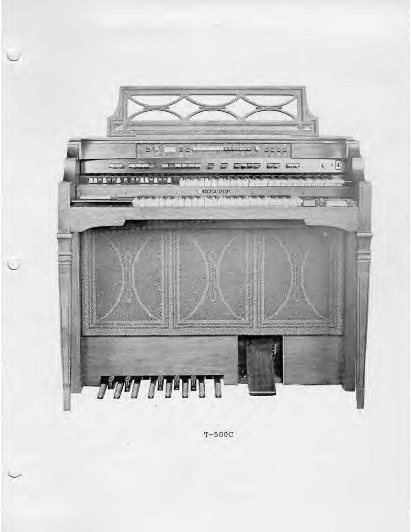
T-500C
TABLE OF CONTENTS
PAGE
INTRODUCTION 1
V
SPECIFICATIONS iv
SECTION I - HOW THE ORGAN OPERATES
1-1 General 1-11-2 Tope Source — ——- 1-11-3 Pedsa Tones 1-3
1-5 Pedal Keyboard 1-6
1-6 Harmon! Tonebars 1-6
1-8 Expression Pedal — 1-71-9 Control Tabs 1-71-10 Preset Tabs 1-71-11 Percussion Control Tabs ———— -^ 1-7
1-12 Vibrato Tabs 1-81-13 Reverberation 1-81-1^ Volume Soft, Brilliance Tab, and Reiteration Rate Control—1-81-15 Pedal Rocker Tab, Lower Left End Block 1-31-16 Tremolo Rocker Tabs, Lower Left End Block 1-81-17 Auto Chord — 1-81-18 Cassette 1-31-19 Rliythm III 1-9
SECTION II - THEORY OF OPERATION
2-1 General 2-12-2 Tone Generator 2-12-3 Vibrato System 2-12-4 Manual Bus Bar Amplifiers 2-i2-5 Pedal Keyboard and Switch Pedal Keyet Boards 2-i2-6 Pedal Divider & Filter Board Assembly 2-52-7 Recovery and Non-Vibrato Board — — 2-52-'& Vibrato Board Assembly 2-62^9 Expression Pedal Circuitry 2-62-10 Power and Reverberation Amplifier Assembly — — 2-62-11 Power Supply Circuit 2-72-12 Phone Jack 2-72-13 Special Power Sources 2-72-14 Percussion Board Assembly -^-^2-7
2-15 Auto Chord Board ——— —2-11
2-17 Rhythm 111 — 2-14

TABLE OF CONTEBTS (cont'd)
PAGE
SECTION III - DISASSEMBLY
3-1 General 3-1
3-2 Removal of Organ Top — 3-1
3-3 Upper Manual Key Removal ^——-——3-13-4 Lower Manual Key Removal 3-1
3-5 Tonebar Assembly Removal (Entire or Partial) 3-1
3-6 Pedal Tonebar Assembly Removal ———^-^-3-2
3-7 Lower Manual End Block. Semoval 3-2
3-S Caaaetce Kensoval -— —_—^ —3-23-9 Upper Manual Removal -^- 3-2
3-10 Lower Manual Removal ' —3-33-11 Tone Generator Removal ^—~—-^ 3-3
3-12 Power Amplifier Removal 3-3
3-13 Pedal Sustain Keyer Removal '3"3
3-14 Pedal Switch Assembly Removal ______———3^3
3-15 Music Lamp Removal — '•—-""' ' 3-4
SECTION IV - PRACTICAL SERVICE SUGGESTIONS
4-1 General — 4-1
4-2 Vibrato Drive and Recovery Board ^-14-3 Tab Replacement — 4-14-4 Tremolo Speaker Maintenance ~ 4-3
4-5 Raising Organ On Deep Pile Carpet 4-6
4-6 Overall Organ Level Adjustment ——— 4-6
SECTION V - DIAGRAMS
5-1 General —5-1
SECTION VI - PARTS LIST
6-1 Parts Llac Index — —~—~— —^-1PWB Parts List 6-15
THRU6-lS
APPENDIX (Not Included at this time)
A-1 Appendlj: IndiK A-1
11

'S^ LIST OF ILLUSTRATIONS
FIGURE PAGE
1-1 Typical T-5O0 Organ Front View 1-11-2 Typical T-500 Organ Rear View — 1-21-3 Magnet Location on Tone Generator — 1-31-i* Filter Location and Frequency Temilnation on Generator 1-31^5 Manual Wiring Chart 1-41-6 Pedal Keyboard — — 1-51-7 Tonebars and Control Tabs (Partial View) 1-6
2-1 Typical Tone Generator ——— 2-1
2-2 Fundamental Diagram of Vibrato System ^_^_2-2
2-3 Vibrato Line Bok — 2-2
2'A Typical Drum Scanner 2-3
2-5 Percussion Null Adjustment 2-102-6 Percussion Decay Adjustment <-— ^- 2-114-1 Bottom Rail Construction 4-64-2 Placeioeiit of Glides 4-65-1 Logic Block Diagram 5-25-2 Lower Manual Bus Amplifier Board
124-000016, Layout and Schematic 5-3
5-3 Upper Manual Bus Amplifier Board124-000015, Layout and Schematic 5-'*
5-A Recovery and Non-Vibrato Board
,^, 124-000014, Layout and Schematic 5-55-5 Vibrato Board 124-000018, Layout and Schematic 5-65-6 Pedal Keyer Boards 124-000025, 124-O0OO26
,
124-000027 Layout and Schematic 5-75-7 Pedal Divider and Filter Board
124-000178, Layout and Schematic 5-85-S Power and Reverberation Ajapltfier Board
124-000176, Layout and Schematic 5-95-9 Power Supply Chasals 124-000176-173, Schematic 5-105-10 Percussion Board 124-000170, Layout and Schematic 5-115-11 Auto Chord Board 124-000179, Layout and Schematic 5-125-12 Special Effects End Block 125-000073, Layout 5-135-13 Expression Pedal 123-000061, Layout 5-135-14 Drum Scanner, 066-042874 5-145-15 Cassette Recorder Assembly, 121-000139 i 121-000165,
Schematic 5-155-16 Rhythm TIT Block Logic Diagram (125-000082) —5-165-17 Rhythm III Generator and Track Gate Board
124-000214, Layout and Schematic 5-175-18 Rhythm III Selector Switch Board
124-000196, Layout and Schematic 5-185-19 Rhythm III Voicing Board 124-000130 Layout and Schematic 5-195-20 Rhythm III Cable Assembly ——5-205-21 Rhythm 111 Output Matrix Timing Chart, and
Voicing Pattern Chart — -— ______5_2i
iii

TNTBDDUCTTON
This tpsnual contains service InEormatlon covering the T-500 HammondOrgan.
Features of the T^500 are explained in Section I.
Rhythm 111 with Auto Chording of the lower manual and pedal 8' fi 16voicing are the special features of this instrument. Serviceinformation for Rhythm II and Auto Chording are included in thisservice manual. For convenience in locating desired information,this manual Is divided Into the sections Hated below.
I How the Organ OperatesH Theory of Operation
111 DisassemblyIV Practical Service SuggestionsV DiagramsVI Parts List
AppendiJC
SPECIFICATIONS
CA£IHET SIZE45" Wide25" Deep
44V High uich Music Rack
Weight with Bench 235 lbs.Power Input 1.2 Amps,Music Power Out 34 Watts(Per EIA Standards - RS-234)
tv
SECTION III
DISASSEMBLY
3-1 GENERAL - This section
contains instructions for
removal of specific sub-assemblies from the organ*
3-2 REf^OVAL OF ORGAN TOP -
After removing rear panel,
remove two Ecrews fromunderside of rear railnear each end of organ.Lift organ top at fJEORt to
disengage spring fastenerson inside of each cheek
panel. Before lifting top,
disengage plug and groundwire from Rhythm HI unit,also plug for music light.
3-3 UPPER MANUAL KEY REMOVAL -
(a) Remove four screua whichsecure metal cover on control -
pane 1 assemb ly
.
(b) Unsolder Violet and Blacktuisted pair wires, as well as
Yellow and Black twisted pairVdlres, terminating directlybehind lower drawbar Cab, whichare connected to drawbar assem-bly.(c) Remove two large studslocated on ends of controlpanel which secure it to uppermanual
.
(d) Fold control assembly sothat it rests on shelf,
(e) To remove a Black key,loosen its key mounting screwand lift from rear.
To remove a White key, loosenits key mounting screw andthose of adiacent Bl^rk k^vs
as required,
3-4 LOWER MANUAL KEV REMOVAL -
(a) Remove two mounting boltsfrom rear of upper manual endblocks.(b) Remove one screw whichpasses through angle bracketinto upper manual. Thisbracket is located on theinside surface of the cheekblock on the left side.This screw is accessiblefrom the front of organ,(c) Tile upper manual upand back.<d> To remove a Black key,loosen its key mountingscrew and lift from rear-To remove a White key,loosen its key mountingscrew and those of adjacentblack keys as required.
3-5 TONEBAR ASSEMBLY REMOVAL(ENTIRE OR PARTIAL) -
Perform steps "a" through"d" of Paragraph 3-3.
(aj Unsolder wire fromtonebar contact spring tobe replaced. Remove fiberstop retaining screw.NOTE: Be certain that thininsulator is between contactspring and drawbar. Replacecontact, stop, and screwand resolder ulren(b) To replace tonebar or
tonebar knob; proceed as
above, but do not unsolderwire. This will permit
3-1

slider to be removed front
front for Its replacement, ortpob replacement
,
(c) To remove (Complete tonebarassernbiy » unsolder all wiresfrom 17 tonebars and 6 wiresterminating on control panel.Hemove three hex head screwstoward either end of tonebarassembly.
NOTEThe upper asid lower tonebarscan be removed individually,as well as the pedal tonebar.
3-6 PEDAL TONEBAR ASSEMBLYREMOVAL - The Pedal TonebarAssfiTHbly can be replacedIndependently by removal oftwo screws securing theassembly to the phenolicplate. Remove assembly bysliding CO the rear.
3-7 LOWER frt^NUAL END BLOCKfiEHOUAL -
<a) For left end block,remove two round head screwsthat pass through left sideof lower manual top coverone inch inside end block.(b) Remove screw that passesthrough angle bracket intoend black.(c) For right-hand block.Remove two round head screwsthat pass through right-handside of lower manual topcover into end block.
Remove two 1/4" hex headscrews from center o£ metalcassette mounting plate,(c) Remove cassette cableconnections from console^ tipfront strip for clearance andremove cassette.
3-9 UPPER MANUAL EtEMOVAL -
(a) Remove four screws thatretain metal caver on controlpanel assembly.(b) Remove two mounting rearbolts from upper manual endblocks
.
(c) Remove two screws thatpass through angle bracketsinto upper manual. Thesebrackets are located on theinside surface of cheek blocksThese screws are accessiblefrom front of organ.(d) Tilt upper manual up andblock in this position.Remove upper manual frontstrip.(e) Snap off harness clampfrom left side of manual bypulling forward.(f) Unsolder all wires fromterminal strips
(g) Return manual to normalposition.(h) Unplug bus bar wires fromupper manual at bus amplifier,(i) Remove all groundingterminations on rear of uppermanual. Release 3 plasticcable clamps and remove lineboK.
3-3 CASSETTE REMOVAL -
<a) Remove six (6) philllpshead screws from upper manualfront strip.(b) Remove one 1/i" hex headscrew from recessed hole inleft front rail trim block.
Remove tonebar assembly andbase, as a unit, by removingsix screws securing it toupper manual.
(j) Remove manual fromcasework.
3-2
3-10 LOWER MANUAL REMOVAL - 3-12 POWER AMPLIFIER REMOVAL
(a) Perform operations "a
Chrough d" In Paragraph 3-S»
(b) Remove two Lower controlpanels as described underParagraph 3-7. Unplug busbar wires from lower manualat bus amplifier.(c) Keanove two mountiTig endblocks and loosen fourscrews attaching manual tofront rail.
(d) Raise upper okannal andremove lower manual.Reverse procedure forre-ina Calling.
3-11 TONE GENERATOR REMOVAL -
(a) Unsolder all harnessconnections from the genera-tor terminal strip.
(b) Ranove heavy ground ulreIn center of generator.
(c) Remove the AC cover paneland unsolder the five wiresfrom harness.(d) Remove the four boltswhich secure tone generatorto support brackets.(e) Remove control panelcover by removing 4 screws.
1. Remove the brown, red,
orange, and yellow wiresfrom the terminals be-hind the "Vibrato Small"switch.
2. Remove the green, blue,violet, grey, and whitewires from the right-handend of the line box.
3. Unplug shielded cablefrom pins 2 & 3 of thevibrato board.
<f) Release all cable tiessecuring scanner leads,
(g) Slide tone generator outrear of organ.
(a) Release all cable ties andplastic cable clamps fromchassis.(b) Unplug 12-pole plug on topof chassis.(c) On large printed circuitboard, unplug wires fromterminals 3-^, 5-6, 7-8,9-10, 11-12, 19. 20, 27-28,29-30, 31.
(d) On small printed circuitboard, unplug wires fromterminals 1, 2, 3, i*, 6 (two
wires), 7, S, 9, 10.
(e) Unplug all wires from ten-lug terminal strips nearsmall printed circuit board.(f) Remove four screws securingamplifier - two at each end.
3-13 PEDAL SUSTAIN KEYER REMOVAL -
Pedal Sustain Keyers arelocated beneath Power Ampli-fier Chassis
»
<a) Release all f!able ties Inthe speaker area to the rightof the speaker.(b) Release cable tie at right-hand side of Reverb Unit(obtain as much slack inExpression pedal cable aspossible)
.
( c ) Remove the fou r sc rewssecuring power ar^lifier topedal switch base and tiltback power amplifier chassis.(d) Pedal Sustain Keyers arenow accessible and can beremoved by removing appropriatecable harness and mountingbolts.
3-lA PEDAL SWITCH ASSEMBLY REMOVAL
(a) Proceed with steps "a","d", and "f" of Paragraph 3-11.
3-3
(b) Remove mounCing bolts frompedal keyer boards {six fromend board, four from centerboard)
.
(c) Kenxove the tuo mountingbolts which go through thelower cabinet croas member andInto the Pedal Switch Base.(d) TlXt Pedal Ewicch end oforgan approximately 12 Inchesand block.(e) Remove the four mountingbolts which come up through thebotCom of Che cabinet Into thePedal Switch Base, (two ac eachend)
.
3-15 MUSIC LAMP REJ*)VAL - When itbecomes necessary to replaceone or more of the incadescentlamps in the Hualc LightAssembly.
(a) Remove two pieces of ad-hesive backed felt at thefront edge of the mualc lightlens. Tip lens up at frontand slide forward to remove.(b> To remove lasip or lamps,depress lamp into socket andtwist counter-clockwiEe to
release.
3-4

SECTION IVPRACTICAL SERVICE SUGGESTIONS
4^1 GENERAL - This section concalnsmaintenance and practical ser-vicing infoEniation. Peculia.rCechniques are explained Indetaii. Procedures whichshould be obvious are notdiscussed.
4-2 VIBRATO DRIVE AND KECOVERTfBOARD, P/N 124-000018 -
The R821 potentiometer is secat Che facCory, and willnormally require no adjusc-inent. Do not actempt toadjust unless absolucelynecessary. See followingparagraphs
,
Whenever any of che vibratocircuitry has been serviced,proceed according to thefollowing
:
1. Connect a VTVM across '
main speaker leads. Pressdown the TONEBARS and PER-CUSSION tab. All other tabsshould be up. Swell pedalat full volunte.
2. Pull upper oianual 8'
tonebar Co position S> Playkey tfS on upper manual.Note voltage on mecer(about l.iV rms)
.
3. Return 8' tonebar toposition 0.
4. Pull upper manual i'
tonebar Co poslcion 8.
Press down VIBRATO andBRILLIANCE tabs. Playupper manual key ffS, Notevoltage on meter. Ifvoltage is within + 2 db
of reading obtained in
step 2, make no adjustment.If voltage is at more than2 db variance with step 2
reading, adjust R821 to
obtain reading identicalto step 2,
i-3 TAB EEPLACE^ffiNT - In theT-Series organs che tabsate suspended on threepivot rods . However, chejoints becween sections ofrod are concealed by plasticsleeves, so that to the un-initiated, che appearanceIs that of one continuousrod.
The rod ends are butted in twoplaces:
1. In the space becweenVIBRATO ON and REITERATEtabs.2, In che space betweenTHEATER BRASS 16' andCHIMES tabs.
PREPARATORY OPERATIONS -
To prepare the controlassembly for replacementof a tab, remove externalparts of console as re-quired for access and pro-ceed according to thefollowing:
4-1

1, Loosen the controlassembly by removing the
large he>:agDn head screwsand Lockuashers at thebottoin of the assembly at
either end.
2. Remove spring clip fromend of pivot rod nearest to
tab being replaced. Usesmall light hammer to drivepivot rod as far as possibletoward tab to be removed.
2. Place protectivematerial between ends ofcontrol assembly and
console end walls toprotect finish.
3. Raise control assem-bly and support by meansof wooden blocks insertedunder the ends.
4. Loosen power switch andsuing aside.
5» Pull pilot lamp, withshield » from its socket.
6» Reioove screws from top
of switch assembly associatedwith tab to be replaced.Suing aside switch assembly.This completes preparation.
TAB REPLACEMENT OPERATIONSk 1/8 inch steel rod of
sufficient length to reachfrom the near end of thecontrol assentbLy to beyondthe cab to be replaced isrequired^ To replace a tabjproceed according to thefollowing:
1. Note position of springdips and plastic sleeves.Clips and sleeves must bereturned to original positionson pivot rod when work Iscompleted.
3, Apply end of 1/8 inchdriving rod and hammer roduntil it has passed throughthe tab to be rentoved.
Suggestion; Measure distancefrom end of control assemblyto £ar side of tab. Markcorresponding length ondriving tod. End of rod willbe concealed by plasticsleeves and cannot beobserved.
A. Pull back driving rodsufficiently to permitremoval of tab
.
NOTEBlack rubber spacers onpivot rod must be saved, andreturned to original posi-tions when inserting new tab.
5. Pull tab asECDibly towardrear of control assembly toTemove.
CAUTION'Save tab actuating springsfor re-use,
INSERTION OF NEW TAB - ToInsert a new tab proceedaccording to the following;
1. Insert tab assembly fromrear of control. Positiontab so chat driving rod can
4-2

be pushed through tab, andpush or drive cod to meetoriginal pivot rod.
and positions of springs.Take necessary correctivemeasures
.
NOTEReinstall any rubber spacersand plastic sleeves previouslyremoved.
2. Drive original pivot rodsback to original positions,
3. Reattach spring clips toends of pivot rods-
A. Reattach two tab actuatingsprings according to thefollowing:
(a) Note condition of spring.Open ends must be well separa-ted. Bend spring to shape ifnecessary,(b) insert double "U" bend ofspring into end of a smalldrive socket or other similarconvenient tool
,
(i2> By means of the tool,place spring with closed endtoward tab assembly, so thatclosed end engages extruelonin tab bracket.(d) With the aid of the tool,position Open end of springto engage extrusion in bottomof control,
(e) When both ends of springare properly engaged, removetool. If the foregoing stepshave been performed properly,the spring will appear as twoparallel arms.
(f) When both springs havebeen attached, operate tab afew times to assure thataction is correct. If actionIs not correct » check shape
COMPLETION OF WORK - Afterascertaining that tab Is
operating properly, reattachassociated switch assembly.Be sure that switch contactarms are properly seatedabove and below actuatingedges of tabs.
Reassemble organ by reversingorder of disassembly.
4-4 TREMOLO SPEAKER MAINTENANCE
A. LUBRICATIC^l - Motor androtor shafts should be oiledonce a year. For lubrica-tion it is necessary to re-move the Tremolo unit fromthe console. Hanunond
generator Oil can be used asa lubricant.
»OT0R (DRUM) SHAFT - Theoutside bearing in the rotorsupport may be lubricated byapplying a few drops of oilto the felt pad around thebearing.
The Inside bearing may belubricated the same way andis accessible through thethroat of the drum. BECAREFUL NOT TO DRIP OIL OHTHE DRIVE FULLY OR SPEAKERCONE.
M:>T0R - An oiling hole isprovided in the front plateof the large motor tofacilitate lubrication ofthe front bearing. This
4-3
Is accessible through a
large hole in the rear of
the Tremolo speaker assembly.
Lubrication of Che rearbeating o£ the large motorwill require the removal of
the small motor and the
drive wheel.
Lubrication of Che sioall
motor bearings is accompli-shed by applying oil to
the shafts and felt padsat each end of the motor.BE SURE THAT THE PORTION OFTHE TOTOR EHAET THAT MAKESCOWTACT WITH THE DRIVEmiEEL IS FREE OF OIL.
E. SPEAKER REPLACEMEHT -
1. Remove the Tremolospeaker assembly from
conso le
.
2. Remove back cover byremoving nine flat headwood screws.
3. Remove acoustical
materlal-
4. Remove four screwssecuring speaker to baffle.
Most routine service opera-tions are outlined on a cardlocated on the unit. Theyare alao reproduced below.
The belt tension may beadjusted without removingunit from console. For beltreplacement, however^ or formotor lubrication and servic-ing, the unit should be takenout of Che organ console.This may be done quite easily
by removing the (4) Tpountingscrews i^lch secure the unit
In the console. Removal ofthe unit from the console doesnot necessitate disconnectingthe motor power and speakerleads. Thus » the operationof Che unit may be fullyobserved as adjust[aents arebeing made.
BELT TEHSION ADJUSTMENT -
Correct tension £or the rocordrive belt Is extremelyImporCant- Excessive slack.
will cause slow starting andslow operating speed, whereasexcessive tension will causenoisy operation. A properlyadjusted belt will slip veryslightly when starting, butwill be sufficiently eightto bring the rotor up tofull speed In about 5 seconds.
To set belt tension, loosenthe adjusting wing-nut whichis readily accessible throughthe back, of the unit. Bymeans of this wing-nut theentire motor assembly may bemoved as required; towardrotor reduces belt tension,away from rotor increasesbelt tension.
Once the motor is positionedto provide the correct belttension, Che wing-nut shouldbe securely tightened.
BELT REPLACEMENT - Afterseveral years of normal usagea belt may become frayed orworn, and therefore noisy inits operation. Such a beltshould be replaced, and toaccomplish this the entiretremolo unit should beremoved from the organ console
4-4
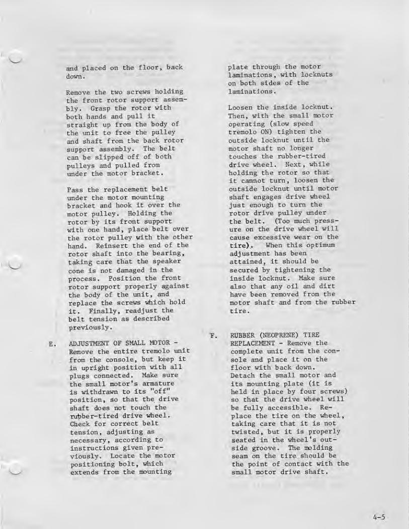
E.
and placed on the floor, back
down,
Reioove the two screws holding
the frooc rotor support asaem-
bly. Gragp the rotor with
both hands and pull it
straight up from the body o£
the unit Co free the pulley
and shaft from the back rotor
support assembly. The belt
can be slipped off of both
pulleys and pulled from
under the motor bracket.
Pass the replacement beltunder Che motor mountingbracket and hook, it over the
motoE pulley. Holding the
rotor by its front support
with one hand, place belt over
the rotor pulley with the oCher
hand. Reinsert che end o£ the
rotor shaft into the bearing,
taking care that the speaker
cone is not damaged in the
process. Position the front
rotor support properly against
the body of Che unit^ and
replace Che screws which hold
It. Finally, readjust che
belC tension as describedpreviously.
ADJUSTMENT OF EhtALL MOTOR -
Remove Che entire Creraolo uniC
from Che conaole, but keep it
in upri^it position wiCh all
plugs connected. Make sure
the sroall motor's armatureis withdrawn to its "off"
position, so that the drive
shaft does not touch the
rubber-tired drive wheel.
Check for correct belttension, adjuating as
necessary, according to
instructions given pre-viously. LocaCe the motor
positioning bolt, which
extends from the mounting
T.
plate through the motorlaminations, with locknuts
on both sides of che
laminations-
Loosen the inside locknut
.
Then, with Che small motor
operating (slow speedtremolo ON) tighten the
outside locknuc until the
motor shaft no longertouches the rubber-tired
driue wheel. Next, whileholding Che rotor so chat
it cannot turn, loosen the
outside locknut until motor
shaft engages drive wheeljust enough to turn the
rotor drive pulley underChe belt. (Too much press-
ure on Che drive wheel will
cause excessive wear on che
tire). When this opcimumadjustuienC has beenattained, it should be
secured by tightening the
inside locknuc. Make sure
also chat any oil and dirthave been removed from the
mocor shaft and from the rubber
Clre.
RUBBER (NEOPRENE) TIREREPLACEMENT - Remove the
coroplece unit from Che con-
sole and place it on thefloor with back down.Detach the small motor and
its mounting plate (iC is
held in place by four screws)
so Chac che drive wheel will
be fully accessible. Re-place the tire on the wheel,
caking care chat it is nottwisted, but it is properly
seated tn the wheel's out-side groove. The moldingseam on Che tire should be
Che poinC of conCacC with che
small mocor drive shaft.
4-5

After makitig sure that the
tire and wheel are free of
oil and dirt, the motorassembly should be replaced
and the drive tension shouldbe readjusted according to
the previous inacruccions.
4-5 RAISING ORGAU ON DEEP FILECARPETING - From time to
time ue are inforined thatpedal keyboard operation is
impaired because of deeppile carpeting.
This can be overcome by
applying a spacer scrip
»
of the dimensions shown in
Figure A-6, to the bottomof the console at each end.
The strip nay be stained to
approximate the organ fin-ish. If stain is applied^a sealer such as shellacor varnish must be appliedto the strip to protectthe carpeting.
piPtm 0- (4| D[niiia.T.
-
ELJW t VtCCTb
^ - - d^EI— P-
Figure 4-1Bottom Rail Construction
GLIDER/SPACER INSTALLATIONINSTRUCTIONS - Be careful not
to disrupt generator mountingor other electrical components^Proceed according to thefollowing;
1. Remove and sec aside Che
metal glides from console.
2. Securely glue and nail spacerstrip to underside of each end of
cabinet and remount (A) metalglides to spacer strips, approx-imately 1 inch from each end.
3. Insert (2) plastic glidesinto legs. (Care must be takennot to split leg).
4. Remove (4) metal glides onbench and install the (i)
remaining glides. Thiscompletes installation. SeeFigure 4-7.
\
GLIDE (PLASTIC)
Figure 4-2Placement of Glides
GLIDE (METAL)
NOTEThe 14" length should be in-creased to 15 3/4" for T^222.In addition to the spacerstrips 6 glides are requiredwhich will be supplied on a
no charge basis. Order PareNo. 032'04146& Plastic Glide.
4-6 ORGAH SETUP PROCEDURE -
All tabs , tonebars ^ rockerswitches and Rhythm III controlsare to be In the "off" positionunless otherwise specified.
4-6

EKpressloTi pedal waxlnitJTn posi-
tion unless otherwise specified
.
Pedals and keys are called for
by number, Number 1 being the
key or pedal at the lowest
frequency side of the manual
Connect oscilloscope and AC
VTVM across stationary speaker
output.
UPPER MANUAL ADJUSTMENT
1. Depress upper Toanual "Tone-
bars and Percussion" tab.
5. Turn off AuCo-Accompaniinent
,
place Rhythm III volume to
maximum, and place Silent/
Sound switch to Silent
position.
6. Depress lower manual"Tonebars" tab,
7. Pull out lower manual 8'
Tonebar to position B.
B. Depress lower manual key ff20
and adjust R5 on Autochordcontrol PUB for output of 4.0
volts peak to peak (+.3 volts).
2. Pull out upper manual 8'
Tonebar and play Key *8.
3. Adjust BS70 (On PWB 12A-
000014) for 4.0 volts peak to
peak (+,3volc)-
4. Push in 8' Tonebar and pull
out 4' Tonebar-
5. Place the expression pedal
in minimum position.
S. Turn "off" lower manual"Tonebars" tab and push in S'
Tonebar,
C. PEDAL LEVEL
1. Pull out pedal l6'/3'Tonebar to position 8.
2. Depress pedal ffl and notethat the output is between 17V
and 32V peak to peak.
6. Play Key tfS and observe the
output to be less than .3 volts
peak to peak, but that it re-
maine audible.
7. Push in 4' Tonebar and return
expression pedal to position,
B. LOWER MANUAL ADJUSTMENT
1. Place Rhythm III in Auto-Accompaniment mode.
2. Rhythm III volume to mini-
mum (off) .
3. Depress Rock push button
and place Silent/Sound tab to
Sound position.
4. Depress any lower manual
key and adjust Rll for minimumaudible output*
D.
3. Depress "Pedal Sustain"switch and play each pedal and
note that the sound will sustainfor approximately 1 1/4 seconds(sustain only when pedal is
depressed)
.
4.
to the "onDepress the l6'/3' switch
position <8')
.
Play pedal ^6 and note chat
the B' sound is approximatelytwice the frequency of the 16
sound
.
PERCUSSION AND REITERATIONNULL ADJUSTMENT
1. Depress the "Reiterate"tab and set the ReiterationRate control at approximatelymid position.
4-7

2. Depress and hold uppermanual Key ^&.
3. Rotace Che PercussionLevel control K557 , fullcouncec-clockwise (up)
.
4. Connect the oacilloscopeto the junction of C503 andfi527 on Percussion Board1Z4-0O0170,
5. Set Che oscilloscope sensi-tivity to 10 mv/cm and roCatethe Alternate Hull (R519) andChe Main Null (R556) controlsuntil the pulses on theoscilloscope are adjusted ComlnimuiQ amplicude.
PERCUSSION AND REITERATICW GAIN
1.
2.
3.
4.
Depress "Celesta" Tab,
Depress "ReiCeratlon" tab,and place rate control inapproximate mid position.
Connect the oscilloscopeto the speaker cerminaland adjust verticalsensicivicy to 1.0 V/cm.
Depress and hold downupper manual key flS,
Adjust Percussion Levelcontrol (R557) until thepercussion output is7+ .3V peak to peak-
Return the "Celesca" to
"off" position and depressthe "Marimba" tab. Thehigh percussion signalshall be 5.0V (-1.5V +2V)peak to peak. The lowfrequency shall be between3.0V to 6.2V.
F, PERCUSSION DECAY TIME
1, Return all tabs Co their"off" posiClon.
2, Play upper manual Key flS
and observe for each tab
5.
the lengCh of time for eachpercussion signal to decay.a. Chimes and Guitardecay time should be approxi-mately three seconds.b. All other percussionvoices should decay approxi-mately one-balf second toone second.
3, Return all tabs to "off"position.
G. VIBRATO LEVEL AND CONTROLS
1. Depress the "Vibrato onUpper" tab "Tonebar andPercussion" tab, and pullthe 3' tonebar toposition 8.
2. Play Key flS and adjust thevibrato level control R821on 124-000018 PWB for 4V(+.3V) peak to peak^
3. Depress the "Vibrato Lower"and"Tonebar3" tabs.
^. Pull out the louer manual S'
tonebar and play louermanual key #20, Note theoutput to be 4V (+ IV -1.3V)peak to peak.
5i Return all tabs and tonebarsto "off" position
,
H. TREMOLO
1. Connect oscilloscope totremolo input on baffleterminal strip.
2. Depress "Tonebars and Per-cussion" tab and pull out3' tonebar to position 8.
3. Turn on "Tremolo On" taband play Key *S and note theoutput to be 4V (+1.5 -1.2)peak to peak.
I. RHYTHM III
1. High frequency level adjustand legato keying test.a. Turn on Snare Dmraswitch and volume maxiDium.
b. Play any lower manualkey approKimately 5 times
4-3

per second and adjust R129of Khychin HI Voicing PWB£or output of becueen1.2V and 1.5V peak Co peak.
2. Low frequency level adjustment.a. Turn Rhythm III tempoc^Mitrol to maxlDLum.
b. Turn Silent/Sound switchCo Sound and notice bass drumis heard. (No rhythm pat-terns switches depressed).c. Adjust R116 for 30V + 2Vpeak CO peak on oscilloscope.
J. HUH
1. Hum reading should be takenwith the control panel covershield^ music lamp installed,and Tremolo tablet in SLOWposition. Organ nrust meetHum requirements with AC plugin either direction.
2. Place all other cabs, tone-bars, and Rhythm III switchesIn the "o£f'* position anddepress the following tabs:
Tonebars & PercussionBrillianceTurn on Music Lamp
a. Hum level should be lessthan .120 volts RMS uith andwithout scanner rotating.
b. T-500C - with Che recorderplay button depressed, record-er volume in maximum position(without tape), hum Levelshall be less than 70 mv RMSwithout scanner rotation.
c. Depress the Revert I andII tabs. Hum level should beless than ,070 volts RMSwithout scanner rotation.
i-9

CHART 4-1 ALIGNMENT fi PEBFORMA^CE CHECK T-500C
Step

SUBJECT: TRIGGER ReilABILITV IMPROVEMEKT
REFERENCE: 124-000170 PERCUSSION BOARDModel T-500
SYHPTOM: Intermittent Ik harmonic divider IC-501 Crisgerlng. iVj. Har-
monic iB part of chime voice on percussion)
CORRECTION: Replace R559 (100 ohm) with Jumper.
Change C513 from .00^7 to .015.
J il r-F
IHIT r-F
luii Mr iciBi} o-SH lit
iH^-^^C).
r^
CHiHIKj
'"Om O-EI^DO O-HinK) CKHHhO0-{I>n>0 0-{I^T£>o o^iPo ^„r*0
SUBJECT: PART NUMBER CORRECTIONS
NATURE OF CHANGE;
i. Refer to page 6-5, of service manual, console-top front view.Lower manujl right hand end block pa^t number should be 025-0^6747Instead of 025-028A07.
Z. Refer to pjJ?;e 6-6, console rear view, top connector numbershould be C05-'0i3363 instead of 005-0^330^.
-4-11

SUBJECT; ttHYTHJ^ 1X1 C12i-0O00S2> SUBSTITUTION PLUG
Purpose Is to operate organ with Rhythm III removed,
PatrCE needed:
One Female Plug 00^-030973Seven Female Pins 007-03073^
,Two Resistors (8,2K) 600-020711
One Resistor (ISOfiSU) 60A-O7O121
V\AA
13) @ Q )
(5) 5) ® © (i)
© ® ® © ®
e.?K
4-12
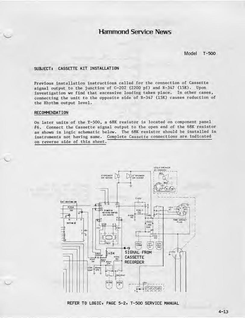
HaTDTTiond Service News
Mode! T-500
SUBJECT: CASSETTE i<IT INSTALLATION
Previous installation Instructions called for the connection of Cassette
signal output to the Junction of C-202 (2?00 pf) and R-347 (15K). Upon
investigation we find that excessive loading cakes place. In other cases,
connecting the unit to the opposite side of R-347 (15K) causes reduction of
the Rhythm output level-
RECOMMENDATION
On Later units of the T-500, a 68K resistor is located on component panel
fl6. Connect the Cassette signal output to the open end of the 68K resistor
as shown in logic schematic below. The 6eK resistor should be installed in
instruments not having same. Complete Cassette connections are indicated
on reverse side of this sheet.
Ww CJ : _[i_[|gg©@|
;
RE^R TO LOGICi PAGE 5'2i T-500 SERVICE MANUAL
4-13

HBHCflaEjH
SPfAriEPTEnillNiVL
CONNECT THRU 63K TOJUNCTION OF C303 <2200 Pf)
AND H343 t27K) ON SWITCH
PANEL BOARD #6
BlCur iVWDIQLUGTiltmALSrHkP
PIN NC5 OF POWSUmr CHASES
GBQUmnG lUS «M Of UPPEIf
HMUAL LEFT SIOE
CONSOLE COWECTIONS
ID PIN MO.
cteamiziowBS ofoissitie
4_2j ^^s^ss^ 5
o4
?
SHIO
CLD
I
3 tfitn
I
I
I
i ffiLi
^ YIELDED CAKF
GRM
TTITHIIUL STRIP AS^
0&3-CH8S39
CONNECT THRU 6EK TO
JUNCTION OF C303 (2200 pf
J
Ai-JD R343 (27K) ON SVITCH
PANEL BOARD i''t
SPEAK EftTERUiMl
»ICHE HJIMO iDLUe iCftHIHllL STRIP
PIN6 OF POWEH SUf^LT OlASSlS
GffQUflDIWE lUCREAR OF
UPPER MfllUL IE ET&LClE
CONSOII CONNECTIONS

SECTION VDIAGRAMS
5-1. GENERAL. -This section contains diagrams which illustrdte the foregoing text and provide
information necessary to proper organ servicing.
^^^

lOWEfl PilAHU4LTgHCQ#Aa
,0017 T 47K
e/B
I
I
Ile?
I
I tooI
I 6SI
I ^I
UH3I2020
FnDlll^o^£
EENEHA1CP
m^ER PtUNUdL rgrVEBARS
[^ EE ^ Ep
-L
...w^L
f« f5 34-s 31 27 ?4 » 23 H 3D S4-e—a—a—
&
llQWVPfMMVI*-*SWPPqOHVPP
ftQMVPPaetftpp
.JEUtf££.jaw^"
'"fc^p"
X(MT
FIGURE 5-1LOGIC BLOCK DIAGRAM
T T T T
Iffl'OODOl*
IXHAEPUAtKML AUTDCHOADKEVIH«
4:
-9
:r
fl40f EH
a9K
033
390
pCl'OOCHiS CAESfTE'RECORDER PLfll^P
I500SEfiie5D*JL'.
ufii
EXPRESSIONPEPflL
i23-D0oaei
^13 'psan
PSSfl15 K
T r SVieitfTD avyii aRECOVER-. *
124-OOaJlf
-a—a
II 3
4|—
I
^>l^>Sl"i^^^rr
IE4-H>0L7O
TniE4ICL
] 1P3
r
LfT
W35T
r IS P?
tjr
nJ-r
REITRATE
[cnnn*! Luujrj fbNH
5-2
PBE9
HlfOjV R42aB^
-L-eBQpr
6«K
1
|@| ^^ I
BLENT RWm»J 5TT
P6QI RNS 4.r
»35i
lOOK
fr35l«—rji^,—
IBK
JT^'
QUID CMQPDCONTHOL PW&154-000179
^9
]7
l«
IS
II
107
Toia/Bswircn it
10 «/6 StVlTCH IS
PEI>BLSUBIiUH 1;
J«
UK
-A-^lW»-
WHT/BPK29
WlfT'RE
WHT
%PfOALSi/flTCh9D I
1^4-000035
^U 3
nirrTiiirJiT
fj
1 '2sr
re
-—
a
WD a
11^-
10..
'3' -
91 -
10
BO sIE4 -000026
9
GBfi.
WHT
PEDAL ^MlCHBD 3
I24-00COZ7 lift
I9K
I'D
'-L
J
l2StEAri[fl
0I4-C?;33
:fi^
|l^"sP£A«Eft0*4-02^397
*"-*I O
-en202!
<23 POWIRBREVEHfi AUPBO
E2C0blI—,wi-||_R547rSK
LESLIE ^PCAriEREZr-Mp03p_^_
RED
L^OrfT
<^L
©0<D®
|®©@®.) J_
_PqBiER_5UPPLV
AC
PILOT LiP*•12
©^
11
l^lVU-DIUJ^Efl Bi
PLIEHHFJl24-rJD017fl
•"O? R40J CC4034700 aiK ^EHO
PEDfli-KEYftG g
I CUrCur Kim 1
iiDcanniTaBI
09*-0463M
SH la2 WVC-C
^IV
.?SV
UUW LiMPS*lTOM
III.AUP3

TUfQ. -IB-bl
(5~C ) ^i<h:i::zk> qotim^\
Wo »^(p^TT^ <>{mIl-o O-CED-e »- i
rScTTS) cHTTTH) 040-© «<^
9^ J
(STTT^ CHEiiK) O-EIhO ©.^
n]-o &{OEi-© «*P4
C§cijjg) QfFT^>e o-aiIH> •
Lffl/Efl. MrtHDAL BUS AMPLIFIER SOftED (I?ft-000016)
TERHLHanCHni#

BE W
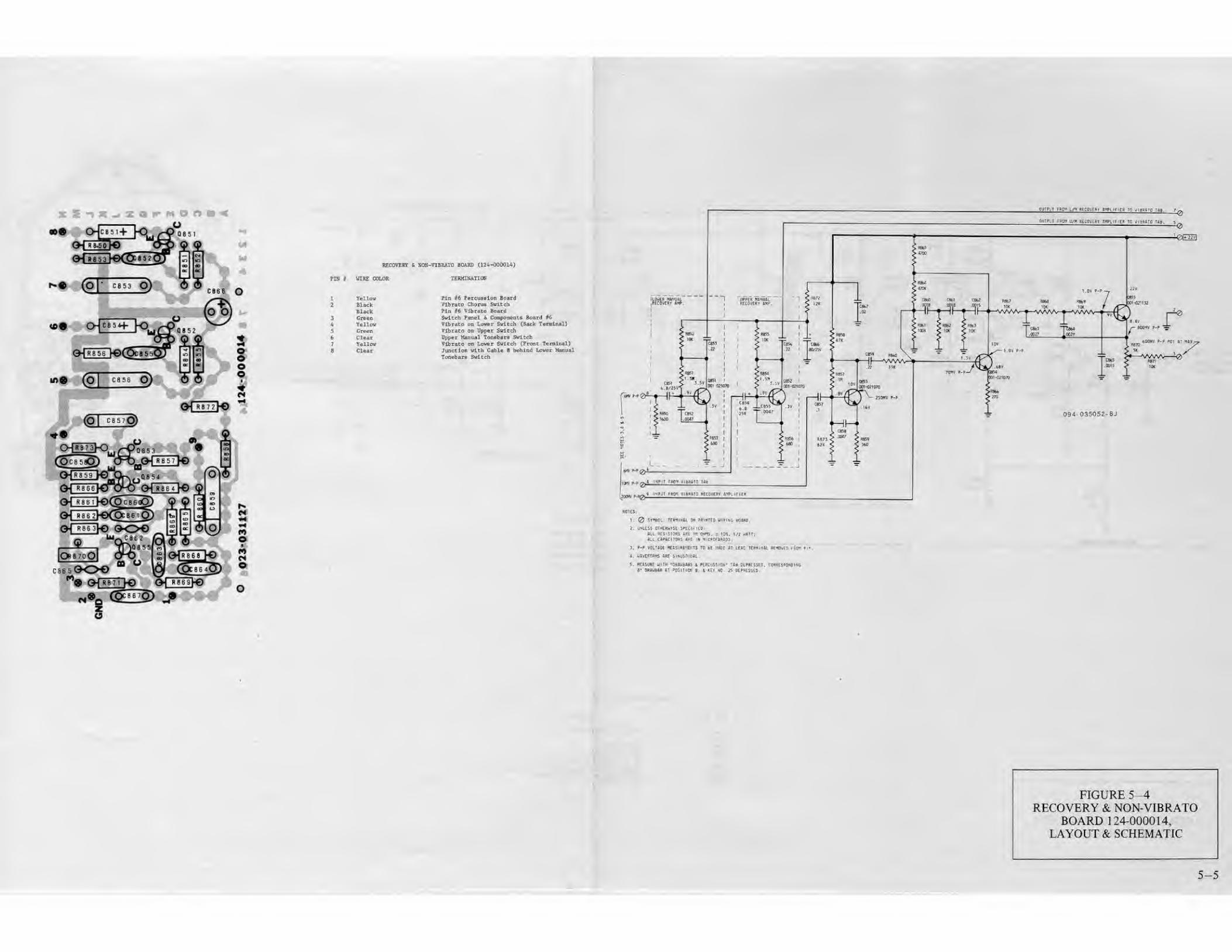
1>- M O A ^ ijmr tiy' \r' hecoe^if i^humb tq i\tai'o 'm fjy.
zo
PIH HlEL COLOP TKBMIHATItW
1

INPUT FBDH
VIBBAIQ TUB
HMtf P-P
\vtw p- p O-INPUT FROM SCAintR
VIIRJITO CtBIVE AflPLIFkEI
^OVPf
l^dHVPP
CS07azz
4
CJO«J3H > ]i|
"T^MPF
OUTPUT TO VIBKTO UHl BOX
€)•"
5 5VDC
cm
750IIVPP
4' I'SIS
<330t
h
^ 50VPP
22V
I
4 3VDC
Oto;
ceo91
i- 1M?0
W^ ^ DUlPur ^DHV P-P PCT A' M>i
^o
irePJtTO BECOVlJtY
094-0350S?-9ll
(JI — 001 0ilO7O
0:5-M]-0?]]33
fl4— 001-0?i2M
W*oi-oziia?
g o-f^s"^7i-o oHI«^IKj_o-IhlII-o
2 o-CEllll-o
VURjMO BOAB 02^-000010)
FIGURE 5-5VIBRATO BOARD 124-000018,
LAYOUT & SCHEMATIC
EFl 9

1- micfs^ [MHft-iSE inciinD-
P6JW1L KEVeH ROAM fll a2'i-OD00251
pia v

470
4-I5V
©Bh
TERMINAL ON PRINTED WIPING BOiRDWAVthORMS P'PJNDICATIONS OBTAINED WITHLOW C PEDAL DEPRESSED
0701 001-02(070
Q70?lhrii7O5 OOI-02IP33
0706fhru710 001-0^1132
PETJAL mVIDm IDJUIP (124-000173)
Pin 1

![Untitled1 [studio250.fr]studio250.fr/docs/hammond/HammondTimesVol31No2-Fall1969.pdf · Ethel Smith discovered early that the Hammond organ ... needed to play the organ and the coordination](https://cdn.vdocuments.us/doc/165x107/5a8acb177f8b9a78648c0490/untitled1-smith-discovered-early-that-the-hammond-organ-needed-to-play-the.jpg)


