USER MANUALKeep User Manual in vehicle
IN-100UM

IMPORTANT SAFETY INFORMATION The Halo is not intended to replace regular pressure-checks and tire maintenance practices as specified by the FMCSA in their Compliance, Safety, Accountability (CSA) Program. Aperia encourages users to take care of their tires and Halos, both of which are important for their safety.
The Halo device, its accompanying parts, and the installation process itself do not present any risks for the individual doing the installation or maintenance if the instructions are followed. For personal protection, it is recommended that the installer wear proper footwear, eyewear, and gloves during the installation process and all related maintenance processes and follow all relevant safety procedures. When using power tools, we encourage all installers to abide by OSHA standards and regulations.
Safety
3
The Halo should be installed and maintained in accordance with the instructions in this manual. Proper installation and maintenance of the Halo is critical to ensure proper functioning of the device. Failure to do so may lead to a malfunctioning product or system which, in turn, could result in injury or death, damage to equipment, material or property.
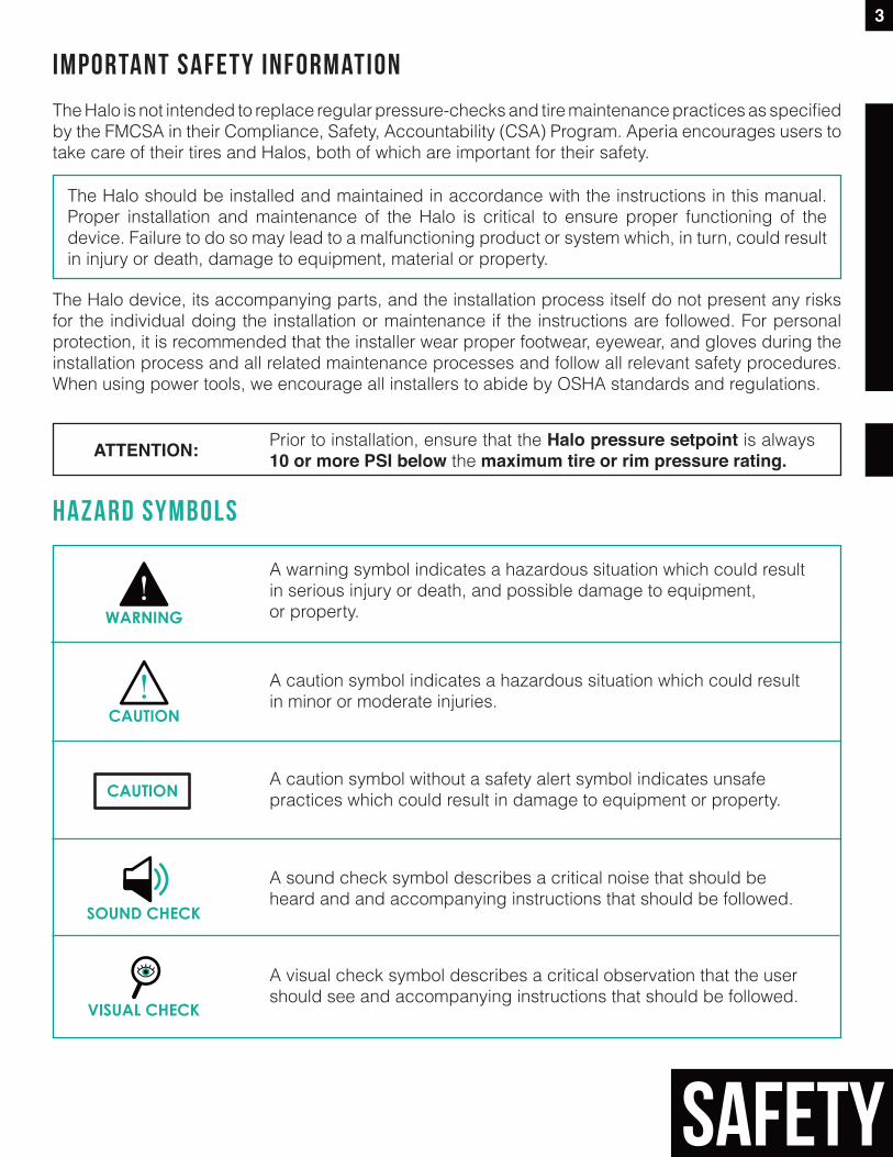
Hazard symbols
WARNING
A warning symbol indicates a hazardous situation which could result in serious injury or death, and possible damage to equipment, or property.
CAUTION
A caution symbol indicates a hazardous situation which could result in minor or moderate injuries.
VISUAL CHECK
A sound check symbol describes a critical noise that should be heard and and accompanying instructions that should be followed.
SOUND CHECK
A visual check symbol describes a critical observation that the user should see and accompanying instructions that should be followed.
CAUTIONA caution symbol without a safety alert symbol indicates unsafe practices which could result in damage to equipment or property.
Prior to installation, ensure that the Halo pressure setpoint is always 10 or more PSI below the maximum tire or rim pressure rating.ATTENTION:
Contents
3 Important Safety Information3 Hazard Symbols
5 Introduction5 The Halo Tire Inflator5 Customer Support
6 Getting Started6 System Components6 Pre-Installation Checklist6 Installation Tools
7 Installation Overview
8 Halo Installation8 Verify Pressure and Orient Halo9 Test-Fit Bracket for Optimal Hose Fit12 Install Bracket13 Attach Halo14 Attach Hose(s) to Tire Valve Stem15 Attach Hose(s) to Halo16 Final Check
17 Halo Uninstallation 19 Halo Maintenance
23 TorqueSpecificationsTable
23 Roadside Call Instructions
4
CONTENTS
READ THE INSTRUCTIONS CLOSELY AS SOME STEPS ARE CRITICAL FOR SAFETY AND PROPER FUNCTION. IF THIS IS YOUR FIRST INSTALL, PAY SPECIAL ATTENTION TO CAUTIONS AND WARNINGS.
IMPORTANT
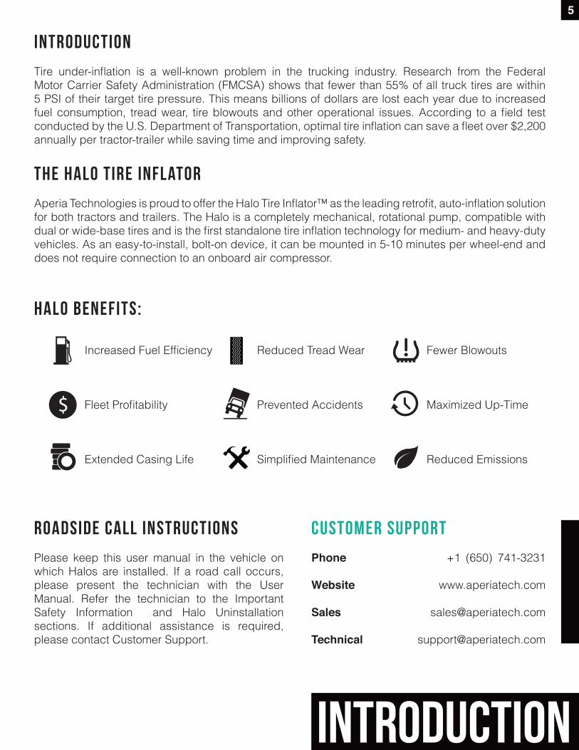
Reduced Tread Wear
Prevented Accidents
Simplified Maintenance
Increased Fuel Efficiency
Fleet Profitability
Extended Casing Life
INTRODUCTION
Tire under-inflation is a well-known problem in the trucking industry. Research from the Federal Motor Carrier Safety Administration (FMCSA) shows that fewer than 55% of all truck tires are within 5 PSI of their target tire pressure. This means billions of dollars are lost each year due to increased fuel consumption, tread wear, tire blowouts and other operational issues. According to a field test conducted by the U.S. Department of Transportation, optimal tire inflation can save a fleet over $2,200 annually per tractor-trailer while saving time and improving safety.
The Halo Tire inflator
Aperia Technologies is proud to offer the Halo Tire Inflator™ as the leading retrofit, auto-inflation solution for both tractors and trailers. The Halo is a completely mechanical, rotational pump, compatible with dual or wide-base tires and is the first standalone tire inflation technology for medium- and heavy-duty vehicles. As an easy-to-install, bolt-on device, it can be mounted in 5-10 minutes per wheel-end and does not require connection to an onboard air compressor.
Roadside Call Instructions
Please keep this user manual in the vehicle on which Halos are installed. If a road call occurs, please present the technician with the User Manual. Refer the technician to the Important Safety Information and Halo Uninstallation sections. If additional assistance is required, please contact Customer Support.
customer support
Phone +1 (650) 741-3231
Website www.aperiatech.com
Sales [email protected]
Technical [email protected]
Fewer Blowouts
Maximized Up-Time
Reduced Emissions
Halo benefits:
5
introduction
6
Getting started
START
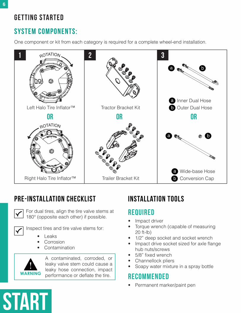
INSTALLATION tools
REQUIRED• Impact driver• Torque wrench (capable of measuring
20 ft-lb)• 1/2” deep socket and socket wrench• Impact drive socket sized for axle flange
hub nuts/screws• 5/8” fixed wrench• Channellock pliers• Soapy water mixture in a spray bottle
Recommended• Permanent marker/paint pen
Right Halo Tire Inflator™
Tractor Bracket Kit
Trailer Bracket Kit
One component or kit from each category is required for a complete wheel-end installation.
SYSTEM COMPONENTS:
1 2 3
ROTATION
Left Halo Tire Inflator™
A contaminated, corroded, or leaky valve stem could cause a leaky hose connection, impact performance or deflate the tire.
PRE-INSTALLATION CHECKLIST
For dual tires, align the tire valve stems at 180° (opposite each other) if possible. Inspect tires and tire valve stems for:
• Leaks• Corrosion• Contamination
WARNING
or or or
ROTATION
b
Inner Dual Hose Outer Dual Hose
a
ab
Wide-base HoseConversion Cap
a
a
b
b
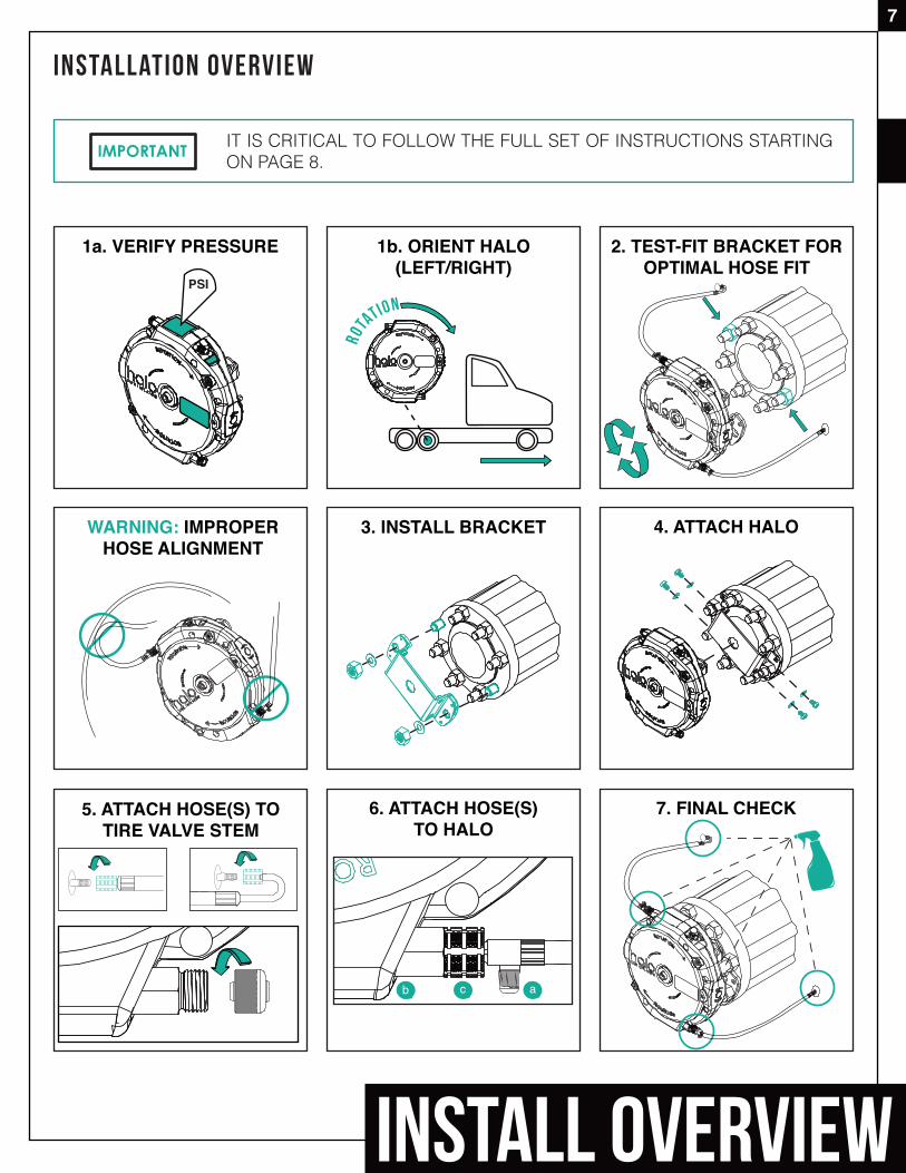
INSTALLATION OVERVIEW
INSTALL OVERVIEW
7
IMPORTANT
1a. VERIFY PRESSURE
PSI
1b. ORIENT HALO(LEFT/RIGHT)
5. ATTACH HOSE(S) TOTIRE VALVE STEM
ROTATION
2. TEST-FIT BRACKET FOR OPTIMAL HOSE FIT
WARNING: IMPROPER HOSE ALIGNMENT
3. INSTALL BRACKET 4. ATTACH HALO
6. ATTACH HOSE(S)TO HALO
7. FINAL CHECK
ab c
IT IS CRITICAL TO FOLLOW THE FULL SET OF INSTRUCTIONS STARTING ON PAGE 8.
install
HALO INSTALLATION
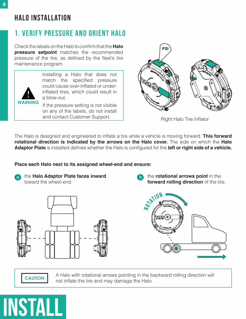
1. verify pressure and orient halo
A Halo with rotational arrows pointing in the backward rolling direction will not inflate the tire and may damage the Halo.
the Halo Adaptor Plate faces inward toward the wheel-end.
a b
The Halo is designed and engineered to inflate a tire while a vehicle is moving forward. This forward rotational direction is indicated by the arrows on the Halo cover. The side on which the Halo Adaptor Plate is installed defines whether the Halo is configured for the left or right side of a vehicle.
the rotational arrows point in the forward rolling direction of the tire.
ROTA
TION
Place each Halo next to its assigned wheel-end and ensure:
Check the labels on the Halo to confirm that the Halo pressure setpoint matches the recommended pressure of the tire, as defined by the fleet’s tire maintenance program.
Installing a Halo that does not match the specified pressure could cause over-inflated or under-inflated tires, which could result in a blow-out.
CAUTION
Right Halo Tire Inflator
If the pressure setting is not visible on any of the labels, do not install and contact Customer Support.
WARNING
PSI
8
9
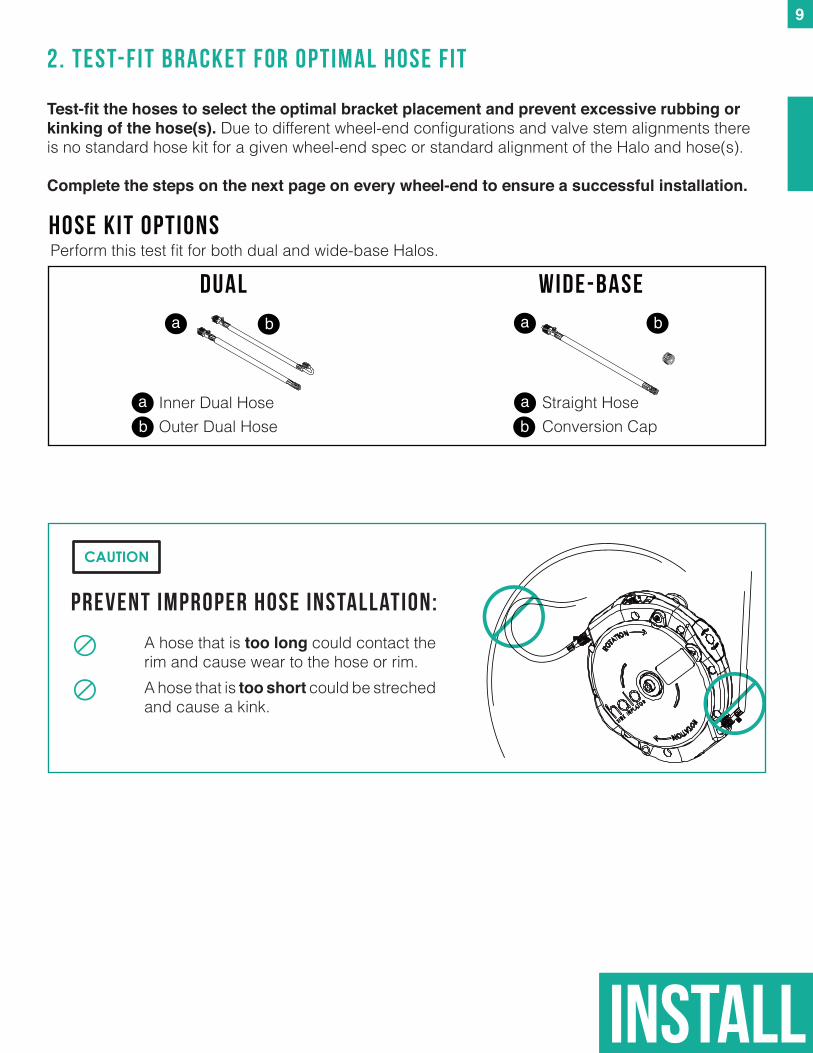
2. TEST-FIT BRACKET FOR OPTIMAL HOSE FIT
Test-fitthehosestoselecttheoptimalbracketplacementandpreventexcessiverubbingorkinkingofthehose(s).Due to different wheel-end configurations and valve stem alignments there is no standard hose kit for a given wheel-end spec or standard alignment of the Halo and hose(s).
Complete the steps on the next page on every wheel-end to ensure a successful installation.
PREVENT Improper hose INSTALLATION:
A hose that is too long could contact the rim and cause wear to the hose or rim. A hose that is too short could be streched and cause a kink.
b
Inner Dual Hose Outer Dual Hose
Straight HoseConversion Cap
a
ab
a
a
b
b
DUAL Wide-Base
HOSE KIT OPTIONSPerform this test fit for both dual and wide-base Halos.
install
CAUTION
install
10
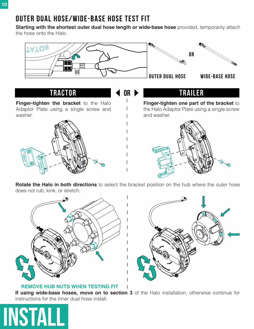
OUTER DUAL HOSE/WIDE-BASE HOSE TEST FITStarting with the shortest outer dual hose length or wide-base hose provided, temporarily attach the hose onto the Halo.
REMOVE HUB NUTS WHEN TESTING FIT
orFinger-tighten the bracket to the Halo Adaptor Plate using a single screw and washer.
Finger-tightenonepartofthebracketto the Halo Adaptor Plate using a single screw and washer.
Tractor Trailer
Rotate the Halo in both directions to select the bracket position on the hub where the outer hose does not rub, kink, or stretch.
If using wide-base hoses, move on to section 3 of the Halo installation, otherwise continue for instructions for the inner dual hose install.
OUTER DUAL HOSE WIDE-BASE HOSE
OR
install
orTractor Trailer
VISUAL CHECK Ensure that your hose(s) are not kinked or rubbing on the wheel.
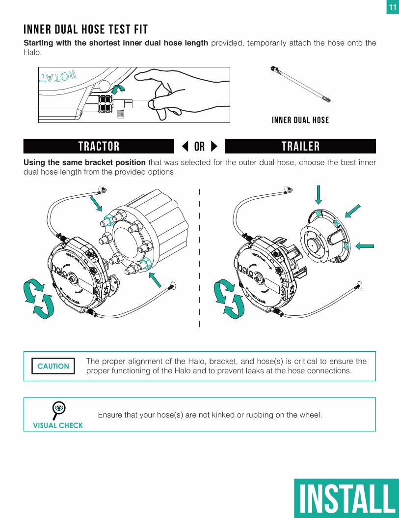
Usingthesamebracketpositionthat was selected for the outer dual hose, choose the best inner dual hose length from the provided options
The proper alignment of the Halo, bracket, and hose(s) is critical to ensure the proper functioning of the Halo and to prevent leaks at the hose connections.CAUTION
11
INNER DUAL HOSE TEST FITStarting with the shortest inner dual hose length provided, temporarily attach the hose onto the Halo.
INNER DUAL HOSE
install
12
orTractor Trailer
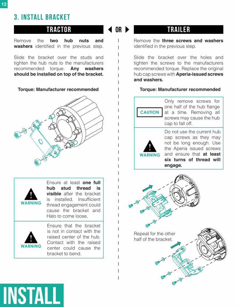
3. INSTALL BRACKET
Remove the two hub nuts and washers identified in the previous step.
Slide the bracket over the studs and tighten the hub nuts to the manufacturers recommended torque. Any washers shouldbeinstalledontopofthebracket.
Remove the three screws and washers identified in the previous step.
Slide the bracket over the holes and tighten the screws to the manufacturers recommended torque. Replace the original hub cap screws with Aperia-issued screws and washers.
Do not use the current hub cap screws as they may not be long enough. Use the Aperia issued screws and ensure that at least six turns of thread will engage.
WARNING
Only remove screws for one half of the hub flange at a time. Removing all screws may cause the hub cap to fall off.
CAUTION
Ensure at least one full hub stud thread is visible after the bracket is installed. Insufficient thread engagement could cause the bracket and Halo to come loose.
WARNING
Ensure that the bracket is not in contact with the raised center of the hub. Contact with the raised center could cause the bracket to bend.
WARNING
Repeat for the other half of the bracket.
Torque: Manufacturer recommended Torque: Manufacturer recommended
install
13
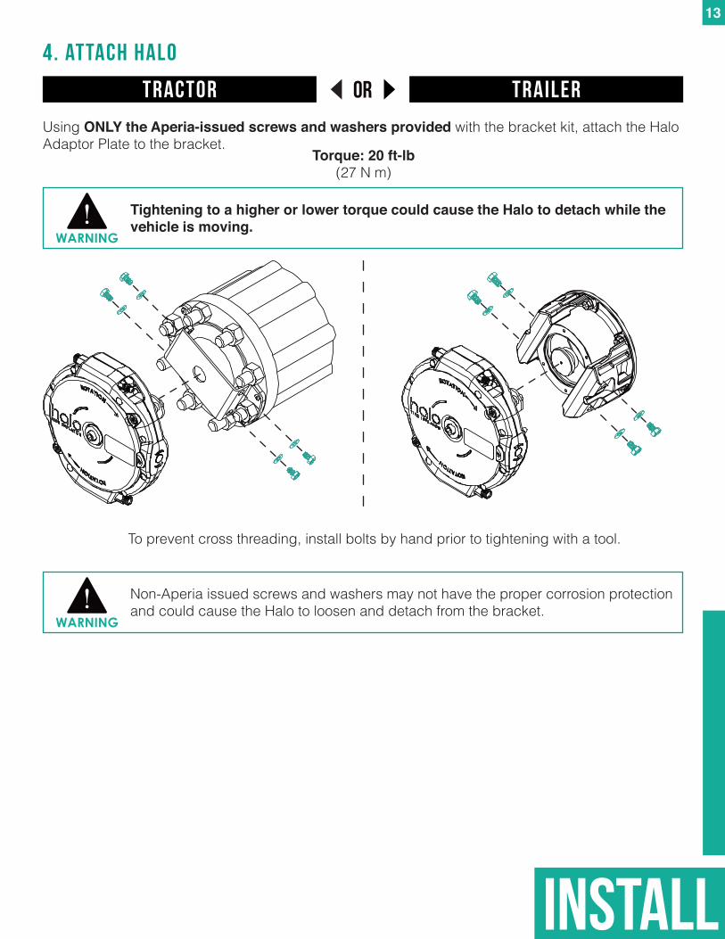
Using ONLY the Aperia-issued screws and washers provided with the bracket kit, attach the Halo Adaptor Plate to the bracket.
4. attach halo
Non-Aperia issued screws and washers may not have the proper corrosion protection and could cause the Halo to loosen and detach from the bracket.
Tightening to a higher or lower torque could cause the Halo to detach while the vehicle is moving.
WARNING
WARNING
orTractor Trailer
Torque: 20 ft-lb(27 N m)
To prevent cross threading, install bolts by hand prior to tightening with a tool.
install
14
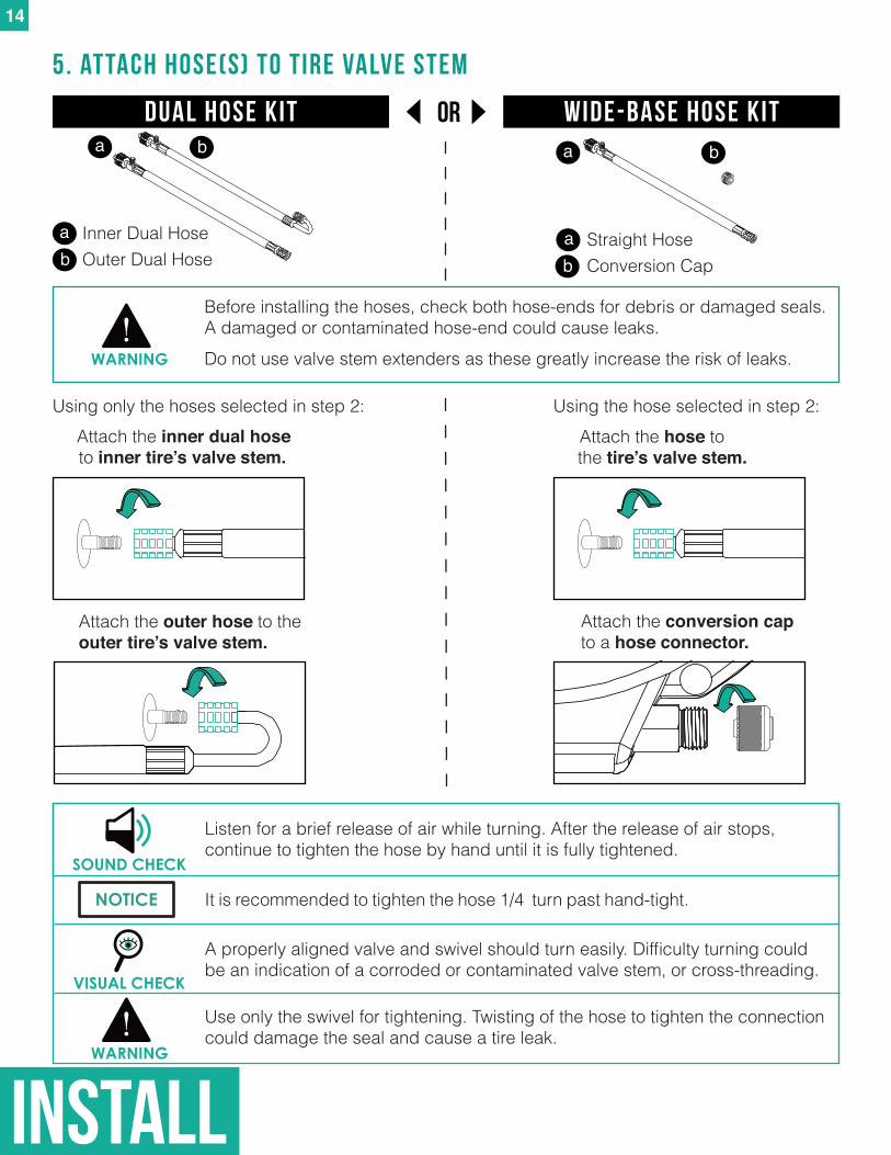
Attach the inner dual hose to inner tire’s valve stem.
5. attach hose(s) to tire valve stem
Use only the swivel for tightening. Twisting of the hose to tighten the connection could damage the seal and cause a tire leak.
VISUAL CHECK
A properly aligned valve and swivel should turn easily. Difficulty turning could be an indication of a corroded or contaminated valve stem, or cross-threading.
SOUND CHECK
Listen for a brief release of air while turning. After the release of air stops, continue to tighten the hose by hand until it is fully tightened.
Using only the hoses selected in step 2: Using the hose selected in step 2:
Straight HoseConversion Cap
a
a
Before installing the hoses, check both hose-ends for debris or damaged seals. A damaged or contaminated hose-end could cause leaks.
Attach the hose to the tire’s valve stem.
Attach the outer hose to the outer tire’s valve stem.
WARNING
Attach the conversion cap to a hose connector.
b
b
WARNING
It is recommended to tighten the hose 1/4 turn past hand-tight.NOTICE
orDual hose kit Wide-Base Hose Kit
Do not use valve stem extenders as these greatly increase the risk of leaks.
b
Inner Dual Hose Outer Dual Hose
a
ab
install
15
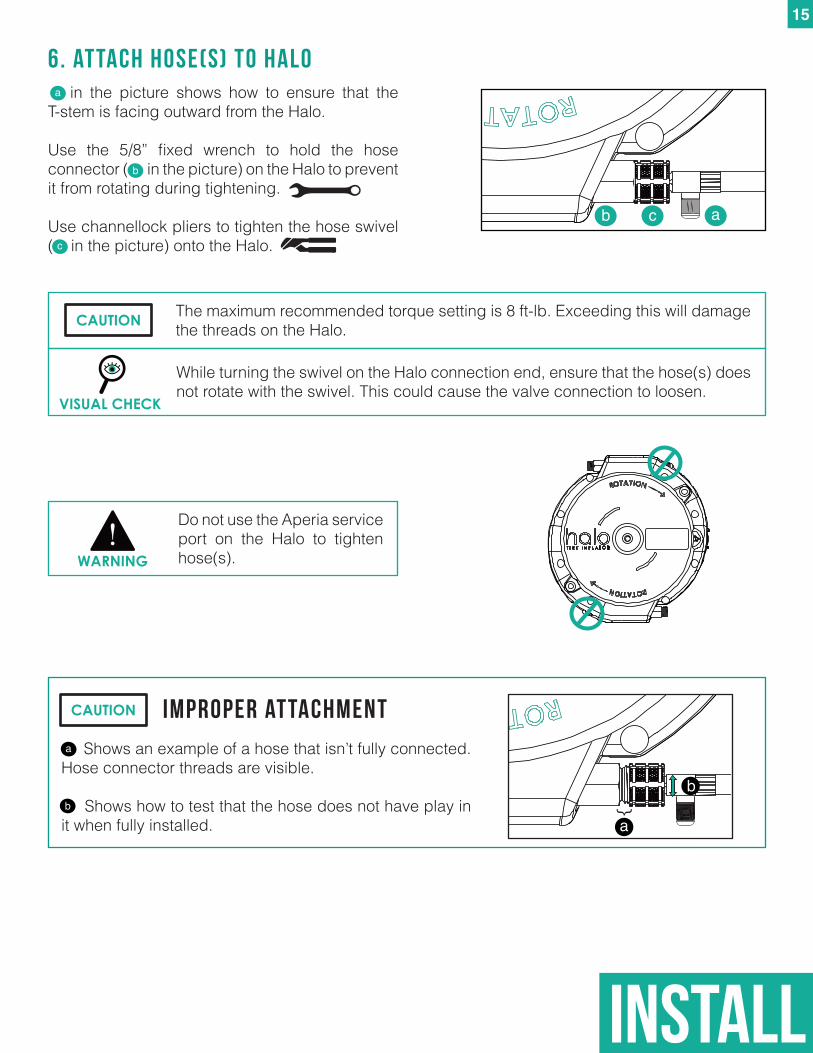
6. attach hose(s) to halo
ab c
Do not use the Aperia service port on the Halo to tighten hose(s).WARNING
The maximum recommended torque setting is 8 ft-lb. Exceeding this will damage the threads on the Halo.CAUTION
in the picture shows how to ensure that the T-stem is facing outward from the Halo.
Use the 5/8” fixed wrench to hold the hose connector ( in the picture) on the Halo to prevent it from rotating during tightening.
Use channellock pliers to tighten the hose swivel ( in the picture) onto the Halo.
a
b
c
... Shows an example of a hose that isn’t fully connected. Hose connector threads are visible.
.. Shows how to test that the hose does not have play in it when fully installed.
Improper attachment
a
b
a
b }
While turning the swivel on the Halo connection end, ensure that the hose(s) does not rotate with the swivel. This could cause the valve connection to loosen.
VISUAL CHECK
CAUTION
install
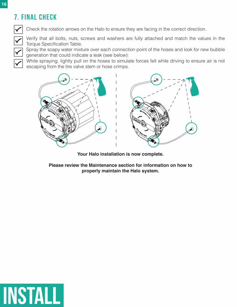
Verify that all bolts, nuts, screws and washers are fully attached and match the values in the Torque Specification Table.Spray the soapy water mixture over each connection point of the hoses and look for new bubble generation that could indicate a leak (see below):
7. Final check
Your Halo installation is now complete.
Please review the Maintenance section for information on how to properly maintain the Halo system.
While spraying, lightly pull on the hoses to simulate forces felt while driving to ensure air is not escaping from the tire valve stem or hose crimps.
Check the rotation arrows on the Halo to ensure they are facing in the correct direction.
16
17
TIRE PRESSUREUNINSTALL
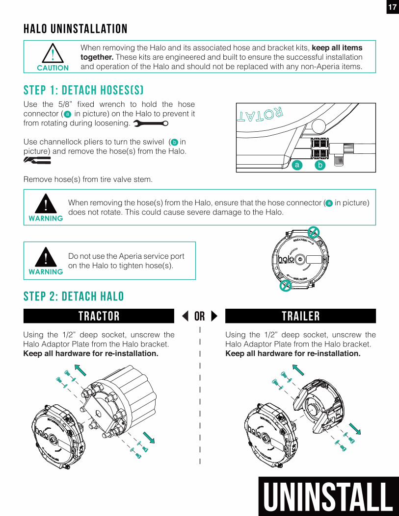
Use the 5/8” fixed wrench to hold the hose connector ( in picture) on the Halo to prevent it from rotating during loosening.
Use channellock pliers to turn the swivel ( in picture) and remove the hose(s) from the Halo.
Remove hose(s) from tire valve stem.
Halo UninstallationWhen removing the Halo and its associated hose and bracket kits, keepallitemstogether. These kits are engineered and built to ensure the successful installation and operation of the Halo and should not be replaced with any non-Aperia items.
STEP 1: detach hoses(s)
CAUTION
When removing the hose(s) from the Halo, ensure that the hose connector ( in picture) does not rotate. This could cause severe damage to the Halo.
WARNING
a b
STEP 2: detach halo
Using the 1/2” deep socket, unscrew the Halo Adaptor Plate from the Halo bracket.Keep all hardware for re-installation.
Using the 1/2” deep socket, unscrew the Halo Adaptor Plate from the Halo bracket.Keep all hardware for re-installation.
Do not use the Aperia service port on the Halo to tighten hose(s).
WARNING
a
a
b
orTractor Trailer
18
UNINSTALL
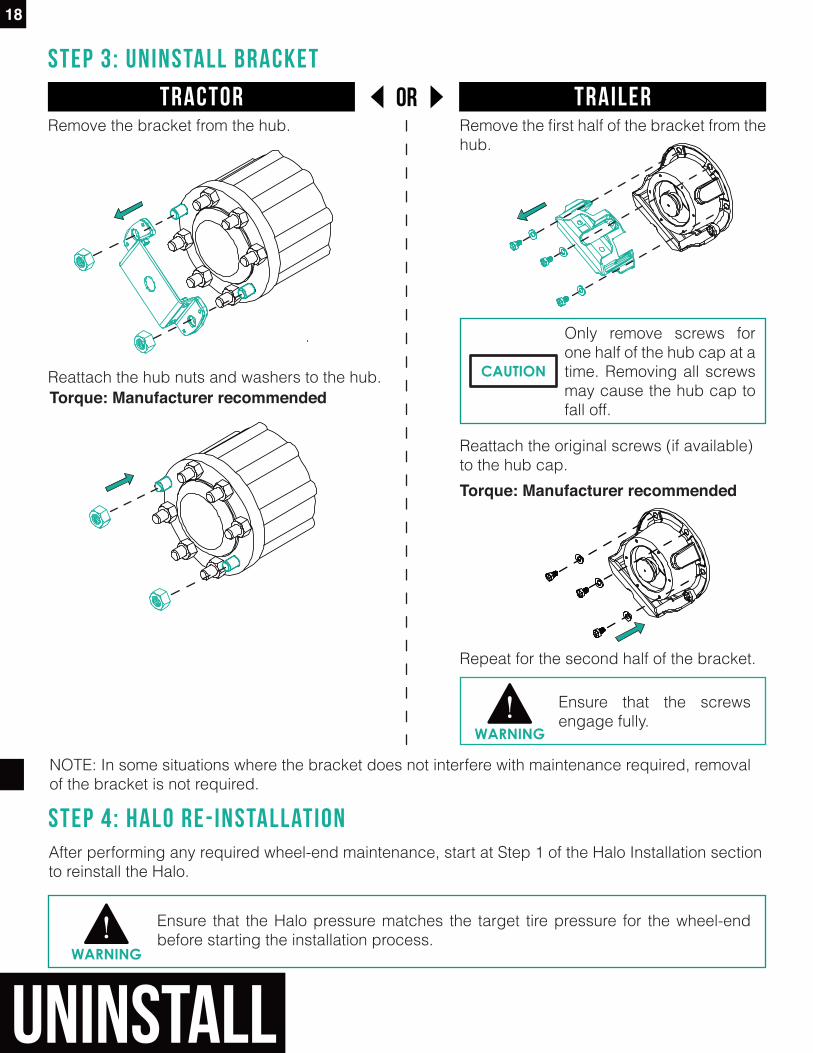
STEP 3: uninstall bracket
Remove the bracket from the hub.
Reattach the hub nuts and washers to the hub.
Reattach the original screws (if available) to the hub cap.
Remove the first half of the bracket from the hub.
Repeat for the second half of the bracket.
Torque: Manufacturer recommended
Torque: Manufacturer recommended
STEP 4: halo re-INstallationAfter performing any required wheel-end maintenance, start at Step 1 of the Halo Installation section to reinstall the Halo.
Ensure that the Halo pressure matches the target tire pressure for the wheel-end before starting the installation process.
WARNING
Only remove screws for one half of the hub cap at a time. Removing all screws may cause the hub cap to fall off.
CAUTION
Ensure that the screws engage fully.
WARNING
NOTE: In some situations where the bracket does not interfere with maintenance required, removal of the bracket is not required.
orTractor Trailer
19
MAINTENANCE
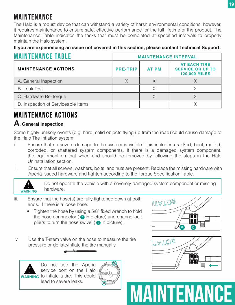
iii. Ensure that the hose(s) are fully tightened down at both ends. If there is a loose hose:
MAINTENANCEThe Halo is a robust device that can withstand a variety of harsh environmental conditions; however, it requires maintenance to ensure safe, effective performance for the full lifetime of the product. The Maintenance Table indicates the tasks that must be completed at specified intervals to properly maintain the Halo system.
Do not operate the vehicle with a severely damaged system component or missing hardware. WARNING
• Tighten the hose by using a 5/8” fixed wrench to hold the hose connnector ( in picture) and channellock pliers to turn the hose swivel ( in picture).
a
ba b
A. General Inspection
Some highly unlikely events (e.g. hard, solid objects flying up from the road) could cause damage to the Halo Tire Inflation system.
A. General Inspection
PRE-TRIP AT PMAT EACH TIRE
SERVICE OR UP TO 120,000 MILES
X
X
MAINTENANCE ACTIONS
XX
XX
XX
B. Leak Test C. Hardware Re-TorqueD. Inspection of Serviceable Items
MAINTENANCE table
MAINTENANCE actions
If you are experiencing an issue not covered in this section, please contact Technical Support.
i. Ensure that no severe damage to the system is visible. This includes cracked, bent, melted, corroded, or shattered system components. If there is a damaged system component, the equipment on that wheel-end should be removed by following the steps in the Halo Uninstallation section.ii. Ensure that all screws, washers, bolts, and nuts are present. Replace the missing hardware with Aperia-issued hardware and tighten according to the Torque Specification Table.
Do not use the Aperia service port on the Halo to inflate a tire. This could lead to severe leaks.
WARNING
iv. Use the T-stem valve on the hose to measure the tire pressure or deflate/inflate the tire manually.
MAINTENANCE INTERVAL
MAINTENANCE
20
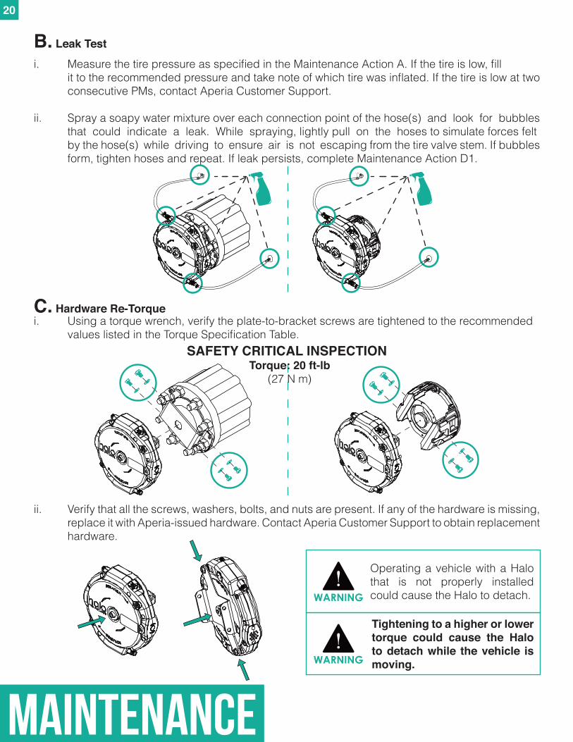
B.LeakTesti. Measure the tire pressure as specified in the Maintenance Action A. If the tire is low, fill it to the recommended pressure and take note of which tire was inflated. If the tire is low at two consecutive PMs, contact Aperia Customer Support.
ii. Spray a soapy water mixture over each connection point of the hose(s) and look for bubbles that could indicate a leak. While spraying, lightly pull on the hoses to simulate forces felt by the hose(s) while driving to ensure air is not escaping from the tire valve stem. If bubbles form, tighten hoses and repeat. If leak persists, complete Maintenance Action D1.
C. Hardware Re-Torque
Operating a vehicle with a Halo that is not properly installed could cause the Halo to detach. WARNING
Tightening to a higher or lower torque could cause the Halo to detach while the vehicle is moving. WARNING
i. Using a torque wrench, verify the plate-to-bracket screws are tightened to the recommended values listed in the Torque Specification Table.
ii. Verify that all the screws, washers, bolts, and nuts are present. If any of the hardware is missing, replace it with Aperia-issued hardware. Contact Aperia Customer Support to obtain replacement hardware.
SAFETY CRITICAL INSPECTIONTorque: 20 ft-lb
(27 N m)
21
MAINTENANCE
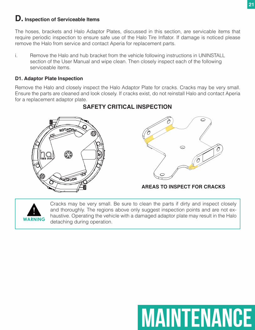
D1. Adaptor Plate Inspection
Remove the Halo and closely inspect the Halo Adaptor Plate for cracks. Cracks may be very small. Ensure the parts are cleaned and look closely. If cracks exist, do not reinstall Halo and contact Aperia for a replacement adaptor plate.
AREAS TO INSPECT FOR CRACKS
Cracks may be very small. Be sure to clean the parts if dirty and inspect closely and thoroughly. The regions above only suggest inspection points and are not ex-haustive. Operating the vehicle with a damaged adaptor plate may result in the Halo detaching during operation.WARNING
SAFETY CRITICAL INSPECTION
D. Inspection of Serviceable Items
The hoses, brackets and Halo Adaptor Plates, discussed in this section, are servicable items that require periodic inspection to ensure safe use of the Halo Tire Inflator. If damage is noticed please remove the Halo from service and contact Aperia for replacement parts.
i. Remove the Halo and hub bracket from the vehicle following instructions in UNINSTALL section of the User Manual and wipe clean. Then closely inspect each of the following serviceable items.
22
MAINTENANCE
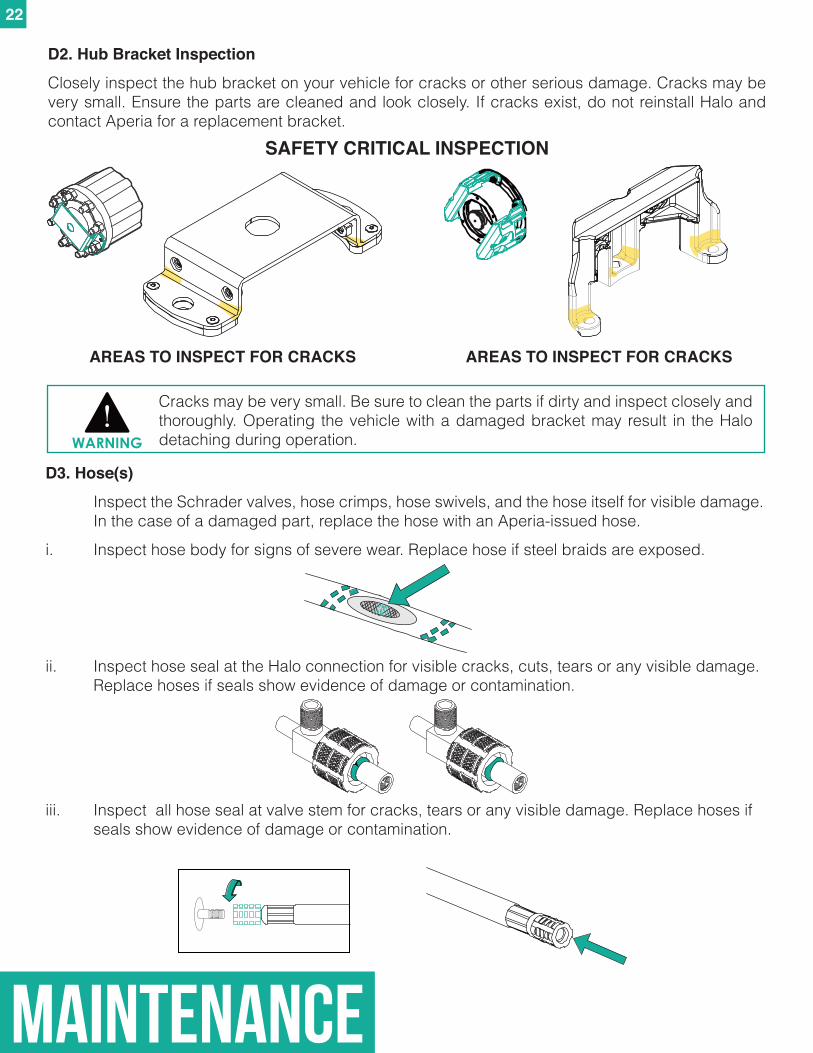
D3. Hose(s)
Inspect the Schrader valves, hose crimps, hose swivels, and the hose itself for visible damage. In the case of a damaged part, replace the hose with an Aperia-issued hose.
i. Inspect hose body for signs of severe wear. Replace hose if steel braids are exposed.
ii. Inspect hose seal at the Halo connection for visible cracks, cuts, tears or any visible damage. Replace hoses if seals show evidence of damage or contamination.
iii. Inspect all hose seal at valve stem for cracks, tears or any visible damage. Replace hoses if seals show evidence of damage or contamination.
D2.HubBracketInspectionClosely inspect the hub bracket on your vehicle for cracks or other serious damage. Cracks may be very small. Ensure the parts are cleaned and look closely. If cracks exist, do not reinstall Halo and contact Aperia for a replacement bracket.
SAFETY CRITICAL INSPECTION
Cracks may be very small. Be sure to clean the parts if dirty and inspect closely and thoroughly. Operating the vehicle with a damaged bracket may result in the Halo detaching during operation.WARNING
AREAS TO INSPECT FOR CRACKSAREAS TO INSPECT FOR CRACKS
23
MAINTENANCE
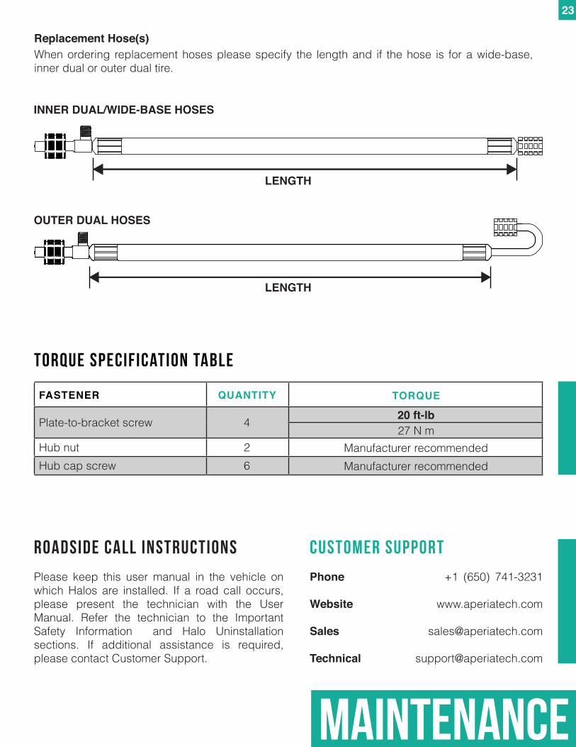
When ordering replacement hoses please specify the length and if the hose is for a wide-base, inner dual or outer dual tire.
Replacement Hose(s)
INNER DUAL/WIDE-BASE HOSES
OUTER DUAL HOSES
LENGTH
LENGTH
FASTENER
Plate-to-bracket screw
Hub nutHub cap screw
4
26
QUANTITY
TORQUE SPECIFICATION Table
Roadside Call Instructions
Please keep this user manual in the vehicle on which Halos are installed. If a road call occurs, please present the technician with the User Manual. Refer the technician to the Important Safety Information and Halo Uninstallation sections. If additional assistance is required, please contact Customer Support.
customer support
Phone +1 (650) 741-3231
Website www.aperiatech.com
Sales [email protected]
Technical [email protected]
27 N m20 ft-lb
Manufacturer recommendedManufacturer recommended
TORQUE

91-00004501 IN-100UM
ÌIN-100UM/ÎRevision B
Ì91-Ç M!ÅÎ


