Download - Group One Presentations

1
Group One Presentations
January 31st, 2019
Preparing to Move to a Solution
Andrew LangPM
January 31, 2019
2

3
Problem: Interdependent Lower Level Requirements
● Systems are all interdependent.● There is a large volume of work completed
that must be documented shared and integrated.
● Numbers and requirements paint a limited picture.

Solution: Get Data and Format Report
4
Technical Progress● Gather “Big” data● Lower level requirements delivered: 70-80*● Tentative total mass sent from Earth: .585 Mg**● Total number of systems: 14
Management Progress● Sections of report proposed● Plan to use report as a “living document”● Final report will be composed in Latex● Automatic labeling and referencing
*As of 4:10 PM 01/30/2019**As of 5:35 PM 01/30/2019

BACKUP: Proposed Report Sections
5

BACKUP: Overleaf Template
6
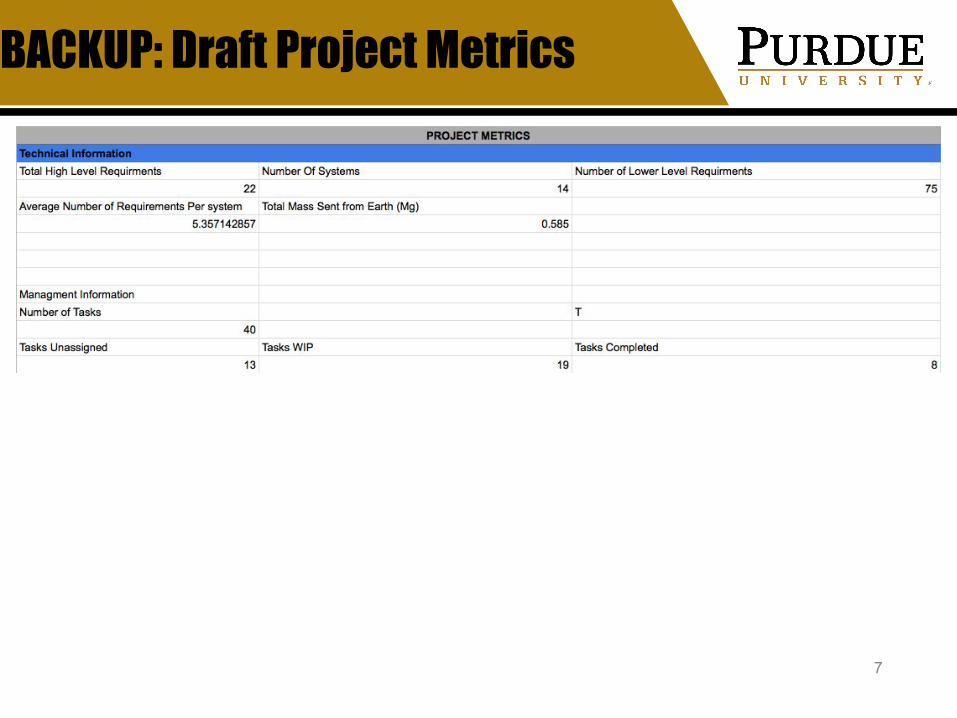
BACKUP: Draft Project Metrics
7

BACKUP: Current Action Items
8

Landing Site Prep - Analysis of Methods to Prepare
Lunar Surface Andres Carrillo
CADMajor Launch Vehicle, Communication Satellites, Ice Harvesters,
Landing Site PrepJanuary 31, 2019
9

10
Problem
Landing site prep involves a system to prepare the lunar surface for construction and safe landing. Complications or problems with the lunar surface:
- Dust/Lunar regolith particles- Meteorites- Not level/uneven land- Potential need to dig or build under surface of moon- No existing structures, road system, landing/launch pad, etc.
Excavation, Leveling, and Construction techniques/machines:- Explosives- Excavators- Bulldozers- Plows- Loaders

Solution
11
Use a combination of excavation explosives and machines/vehicles to prepare the land site.● Explosive should be ANFO (Ammonium Nitrate/Fuel Oil)● Excavator Heavy Duty Bucket from CAT (3.737 Mg, 3.8 m3)● D11T Bulldozer from CAT (104.236 Mg, 172.13 m3)
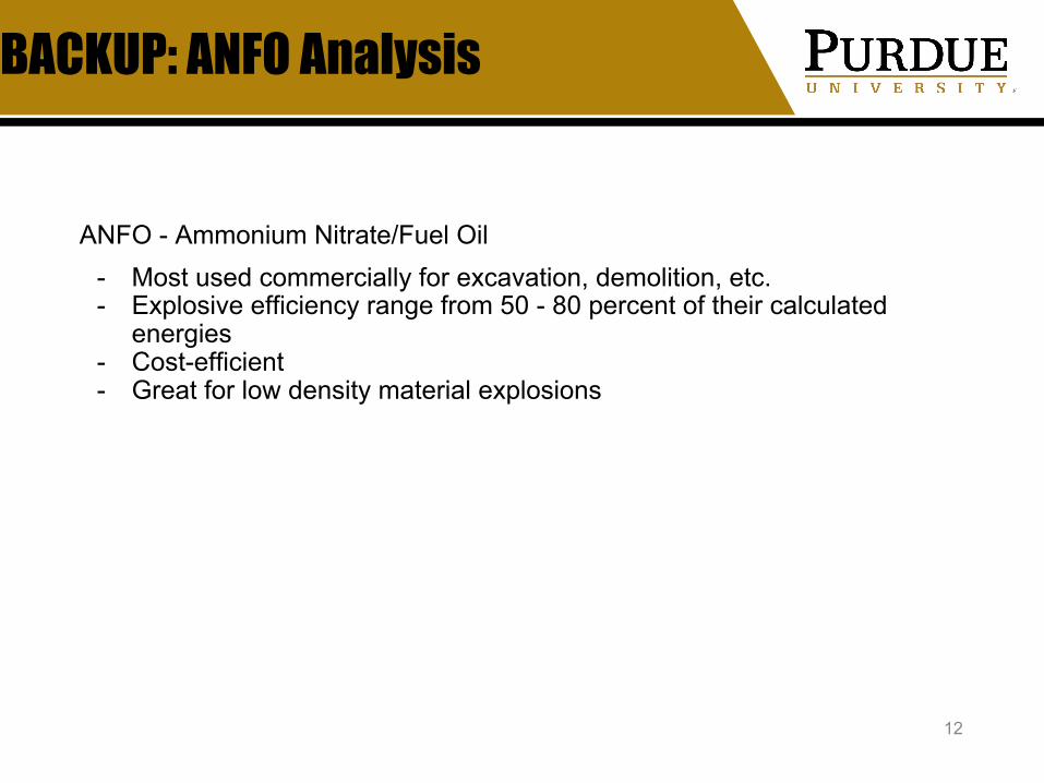
BACKUP: ANFO Analysis
12
ANFO - Ammonium Nitrate/Fuel Oil- Most used commercially for excavation, demolition, etc.- Explosive efficiency range from 50 - 80 percent of their calculated
energies - Cost-efficient- Great for low density material explosions

BACKUP: Heavy Machinery via CAT
13
Retrieved from: https://www.cat.com/en_US/products/new/attachments/buckets-excavator/heavy-duty/2000000591.html
Retrieved from: https://www.cat.com/en_US/products/new/equipment/dozers/large-dozers/18332635.html

BACKUP: Particle velocity mapping code
14
BACKUP: Sources
15
1. Abbaspour, H., Drebenstedt, C., Badroddin, M., and Maghaminik, A., “Optimized design of drilling and blasting operations in open pit mines under technical and economic uncertainties by system dynamic modelling,” International Journal of Mining Science and Technology, vol. 28, 2018, pp. 839–848.
2. Athanasios Goulas, Ross J. Friel, (2016) "3D printing with moondust", Rapid Prototyping Journal, Vol. 22 Issue: 6, pp.864-870, https://doi.org/10.1108/RPJ-02-2015-0022
3. Gibney, E., “How to build a Moon base,” Nature News Available: https://www.nature.com/articles/d41586-018-07107-4.
4. Johnson, S. M., Bourque, R. F., Day, W. C., Gates, R. H., Gilson, D. R., Fraser, R. L., ... & Remboldt, A. L. (1971). Explosive excavation technology (No. NCG-TR-21). ARMY ENGINEER NUCLEAR CRATERING GROUP LIVERMORE CA.
5. Rodriguez, J., “This Is Must-Have Heavy Equipment for Construction Projects,” The Balance Small Business Available: https://www.thebalancesmb.com/must-have-earth-moving-construction-heavy-equipment-844586.
6. Tate, K., “Home On the Moon: How to Build a Lunar Colony (Infographic),” Space.com Available: https://www.space.com/21588-how-moon-base-lunar-colony-works-infographic.html.
7. Wall, M., “Back to the Moon: How New Lunar Bases Will Work,” Space.com Available: https://www.space.com/10634-moon-base-lunar-outpost-technology.html.
Scout Rover: Ice Detection Equipment
Matthew EustaceCAD
Scout Rovers January 31, 2019
16
17
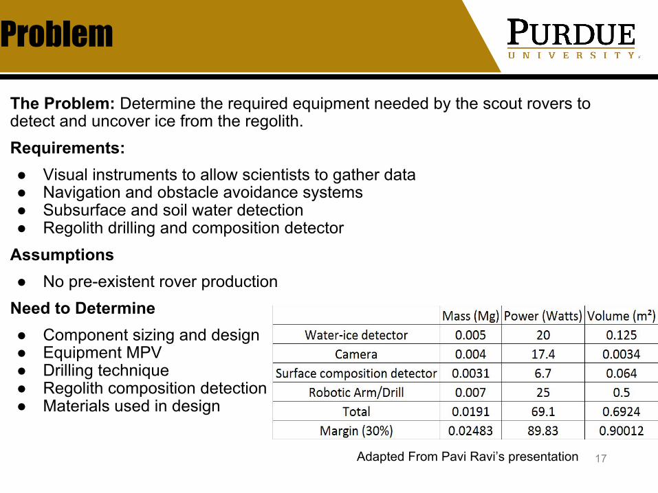
Problem
The Problem: Determine the required equipment needed by the scout rovers to detect and uncover ice from the regolith.Requirements: ● Visual instruments to allow scientists to gather data● Navigation and obstacle avoidance systems● Subsurface and soil water detection● Regolith drilling and composition detector
Assumptions● No pre-existent rover production
Need to Determine● Component sizing and design● Equipment MPV● Drilling technique● Regolith composition detection● Materials used in design
Adapted From Pavi Ravi’s presentation
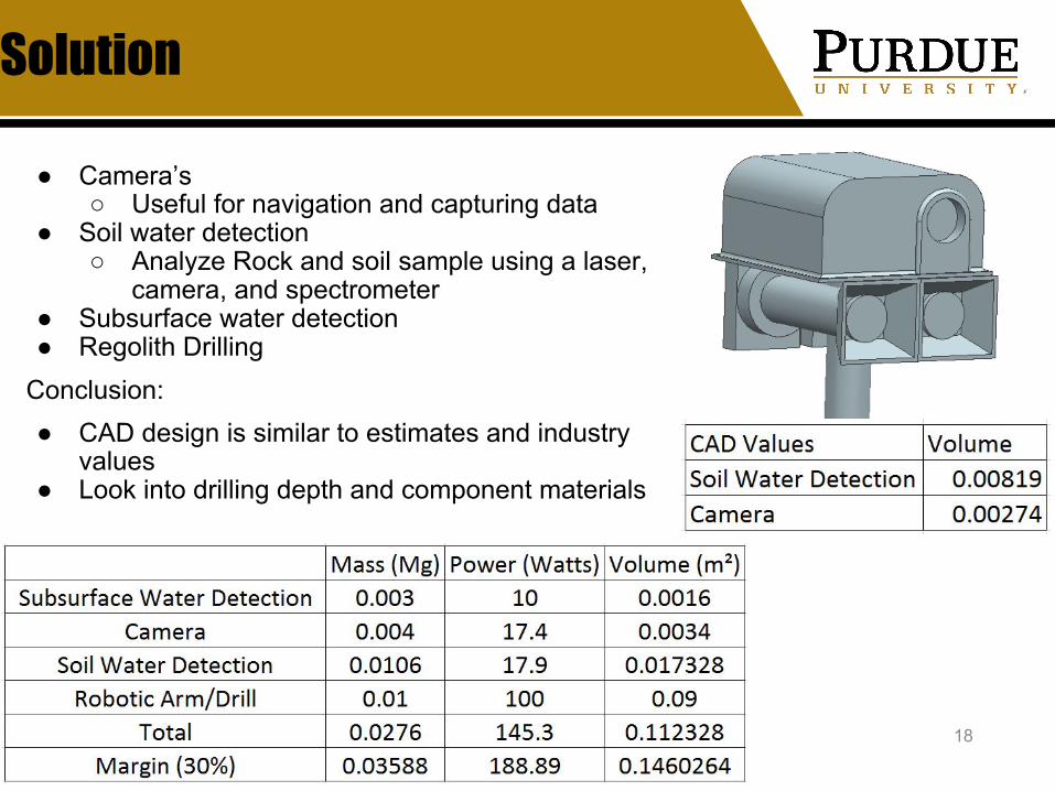
Solution
18
● Camera’s○ Useful for navigation and capturing data
● Soil water detection○ Analyze Rock and soil sample using a laser,
camera, and spectrometer● Subsurface water detection● Regolith Drilling
Conclusion:● CAD design is similar to estimates and industry
values● Look into drilling depth and component materials
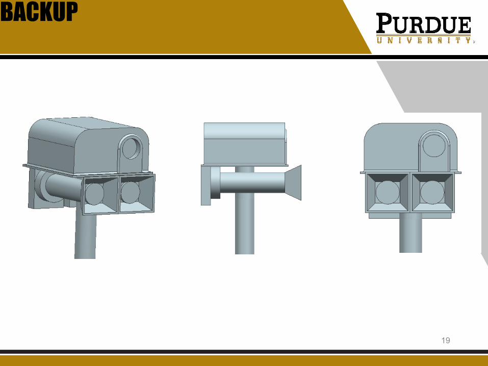
BACKUP
19
Backup
Rover Sensors and EquipmentMatthew EustaceCAD Team
The sensors and equipment needed for the mission were analyzed in order to better understand the rover’s mass, power, and volume requirements. The process is to look at what requirements the rover must accomplish. Research was then performed to find relevant sensors and equipment that meet these requirements. Mass, power, and volume calculations were then performed in order to better define rover sizing.
Camera’sOne necessary requirement is to have camera’s to provide visual data to scientists during the Rover’s exploratory
mission.One possible source of equipment is similar to the Mastcam-Z. It is a camera mounted to the mast of the rover, that
allows colored panoramic imaging, 3D imaging, zoom capabilities, and high-definition video. The Mastcam-Z has a mass of about 0.004 Mg, requires about 17.4 watts, and has dimension of 0.11x0.12x0.26 m and therefore a volume of 0.0034 m2 .
NavigationAnother necessary requirement is navigational equipment. The Rover needs navigational capabilities so that it can
head towards predetermined locations looking for ice. The rover also needs to have the capability to adapt to the terrain and navigate obstacles not seen by ground control. While the GPS system would need to be different, the Mastcam could already provide the capabilities needed for getting data from the terrain ahead. An onboard computer could look at the specified direction of the rover while the images could be analyzed to determine the best route. 20

Backup
Subsurface water detectionA necessary piece of equipment for this mission is a device that can look below the surface of the moon to look for
ice. Satellites can help target areas to deploy scout rovers, but once on the surface the rovers will need to define where to dig. It would take too long to successfully find subsurface ice if the scout rover was blindly digging holes.
One solution could be a sensor such as RIMFAX. This stands for Radar Imager for Mars’ Subsurface Experiment. This sensor uses radar waves to detect changes in the material underground. The instrument probes the ground beneath it and can find materials such as ice, rock, sand, and liquid water. RIMFAX has a mass of 0.003 Mg, power of 5-10 watts, and a volume of 0.0016 m2 or 0.196x0.120x0.066 m. It has the capability to see greater than 10 meters deep under the surface.
Soil Water DetectionAnother necessary piece of equipment is a tool that can analyze the components of soil. This sensor can then look at
soil samples around the rover and help analyze the best place to drill. Possible instruments could be the SuperCam or the ChemCam. Both instruments analyze rock and soil samples with
a laser, camera, and spectrometer. This tool can identify the chemical makeup of rocks, soil, and regolith from more than 7 meters away. They can look at the atomic and molecular makeup of the samples. The SuperCam has a mass of 0.0106 Mg, power of 17.9 watts, and volume of 0.017328 m2 or 0.38x0.24x0.19 m.
Regolith Drilling and Composition DetectorAnother requirement is a drill to dig into the soil once ice has been detected in the regolith. A device will also be
needed that can analyze the regolith sample and see what the composition is. The drill will have to reach a depth of at least 1 meter unless the science team requests a longer length. In order to reach 1 meter, the drill will have to be at least 1.5 meters in length based on various drills in production. So the volume would be about 0.09 m2, require about 100 watts of power, and have a mass of about 0.01 Mg. The Composition Detector is still being researched. 21

References
[1] Lecher, Colin, 2012. “The Ten Instruments that Mars Rover Curiosity willuse to Investigate the Red Planet,” Popular Science Available:https://www.popsci.com/technology/article/2012-07/tools-mars-rover-curosity-will-use-uncover-history-water-and-life
[2] “Rover,” NASA Available: https://mars.nasa.gov/mars2020/mission/rover/[3] Colaprete, Anthony, “Resource Prospector: Evaluating the ISRU Potential of the Lunar Poles,” NASA Available: https://www.hou.usra.edu/meetings/leag2016/presentations/Wednesday /Colaprete.pdf[4] “What are Science Instruments,” NASA Available: https://mars.nasa.gov/mars2020/mission/instruments/.
22

Autonomous Lunar Landing Requirements
Kevin SheridanCommunication and Control
Landing/Deployment Vehicle(s) & Lunar Launch and Descent VehicleJanuary 31, 2019
23

Problem: Autonomous Landing
24
Waypoint Constraints
The Problem: Determine thruster requirements for landing, Determine compute/sensing package mass/power.
Requirements: • Landers must be able capable of correction maneuver.• Landing must be autonomous
Assumptions/Constraints: • Landing consists of 3 stages: zeroing of lateral
velocity, correction maneuver, and vertical landing. • Initial speed at 5 km is 1.69 km/s (from mission design)• Initial Mass: 5000 kg• 4 m X 2 m cylinder• Vacuum Isp of each thruster: 300 s• Maximum thrust: 71000 N

Solution: Thruster Requirements & Sensing/Compute Package
25
Note: Thruster Characteristics, Trajectory parameters, Vehicle Mass/Inertia are configurable in Matlab code attached.
Note: Attitude and Position over time can be extracted from the code. This can be used for a visualization later.
Mass ~ 1 kg
Power 30 W
Sensing and Compute Package
Thruster Configuration: • 4 pairs of angled thrusters. (8 total)• Maximum Thrust Guess: 71 kN (per engine)• Vacuum Isp Guess: 300 s
1 m Camera

BACKUP: Minimum Time Trajectory Generation
26
By choosing this thruster configuration, I was able to use the fact that forces can only be produced in the body frame z axis to compute the attitude of the spacecraft based on its acceleration.
Then, by using the higher order derivatives of the trajectory, the moments required can be computed at any point along the trajectory.
Finally, we can form a linear mapping between the thruster forces and moments and body frame Z force.
The trajectory generator implementation can be found here:https://github.com/AAE450/FutureMoon/tree/dev/LandingAnalysis

BACKUP: Wrapper function to trajectory generator
27
Note: All code can be found here:https://github.com/AAE450/FutureMoon/tree/dev/LandingAnalysis

28
Backup: Trajectory Generator
29
Backup: Trajectory Generator

30
Backup: Trajectory Generator

31
Backup: Trajectory Generator

References
32
Feetham, L., Aouf, N., Dubois-Matra, O., & Bourdarias, C. (2016, July). Image datasets for autonomous planetary landing algorithm development. In Mechanical and Aerospace Engineering (ICMAE), 2016 7th International Conference on(pp. 627-637). IEEE.
Sibley, G., Matthies, L., & Sukhatme, G. (2010). Sliding window filter with application to planetary landing. Journal of Field Robotics, 27(5), 587-608.
Cutler, M. J. (2012). Design and control of an autonomous variable-pitch quadrotor helicopter (Doctoral dissertation, Massachusetts Institute of Technology, Department of Aeronautics and Astronautics).
Data rate determination and link budget analysis
Minduli Wijayatunga Communications and Control
Safe Haven, Orbital Propellant Depot & Launch vehicles January 31, 2019
33
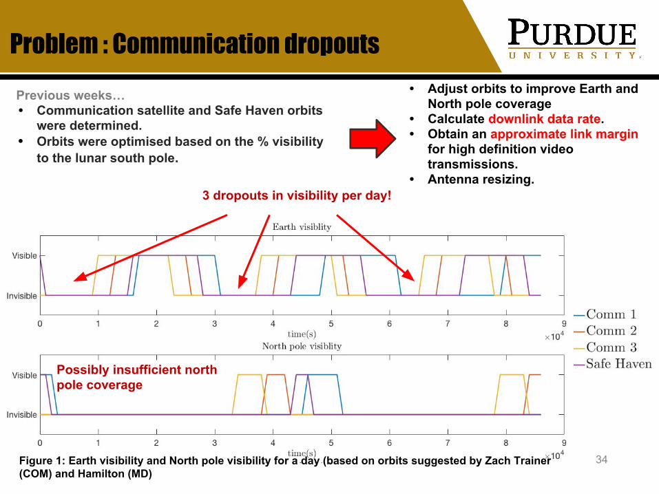
Problem : Communication dropouts
34
• Adjust orbits to improve Earth and North pole coverage
• Calculate downlink data rate. • Obtain an approximate link margin
for high definition video transmissions.
• Antenna resizing.
Previous weeks… • Communication satellite and Safe Haven orbits
were determined. • Orbits were optimised based on the % visibility
to the lunar south pole.
3 dropouts in visibility per day!
Possibly insufficient north pole coverage
Figure 1: Earth visibility and North pole visibility for a day (based on orbits suggested by Zach Trainer (COM) and Hamilton (MD)

Solution: Improved orbits, resultant data rate and link margin
35
Spacecraft a(km) i(deg) e ⍵(deg) Ω(deg) 𝛉(deg)Safe Haven 4567.5 80 (90) 0.6 90 90(0) 270 Commsat 1 4900 70(90) 0.5 90 0(0) 0Commsat 2 4900 70(90) 0.5 90 90(0) 90 (120)Commsat 3 4900 70(90) 0.5 90 180(0) 180(240)
Table 1: Refined spacecraft orbits (Previous data from Zach Trainer (COMS) and Hamilton (MD)
Data rate = 14.26 Mbps(calculation on slide 6)
Figure 2: Earth visibility and North pole visibility of the redefined orbits for a day Table 2 : Antenna gain, diameter and beamwidth
Link margin = (0.69 ±0.21)dB(Link budget on slide 8)
X BAND Gain (dB) D(m) BW
Earth 50 5.02 0.49Commsat
(main) 25 0.28 8.74
Safe Haven/Commsat
(redundant) 20 0.16 15.55

36
Backup : Total coverage of the refined orbits
Figure 4: Earth visibility, North pole visibility and south pole visibility of the redefined orbits for a day
37
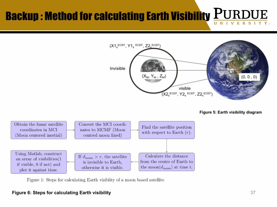
Backup : Method for calculating Earth Visibility
Figure 6: Steps for calculating Earth visibility
38
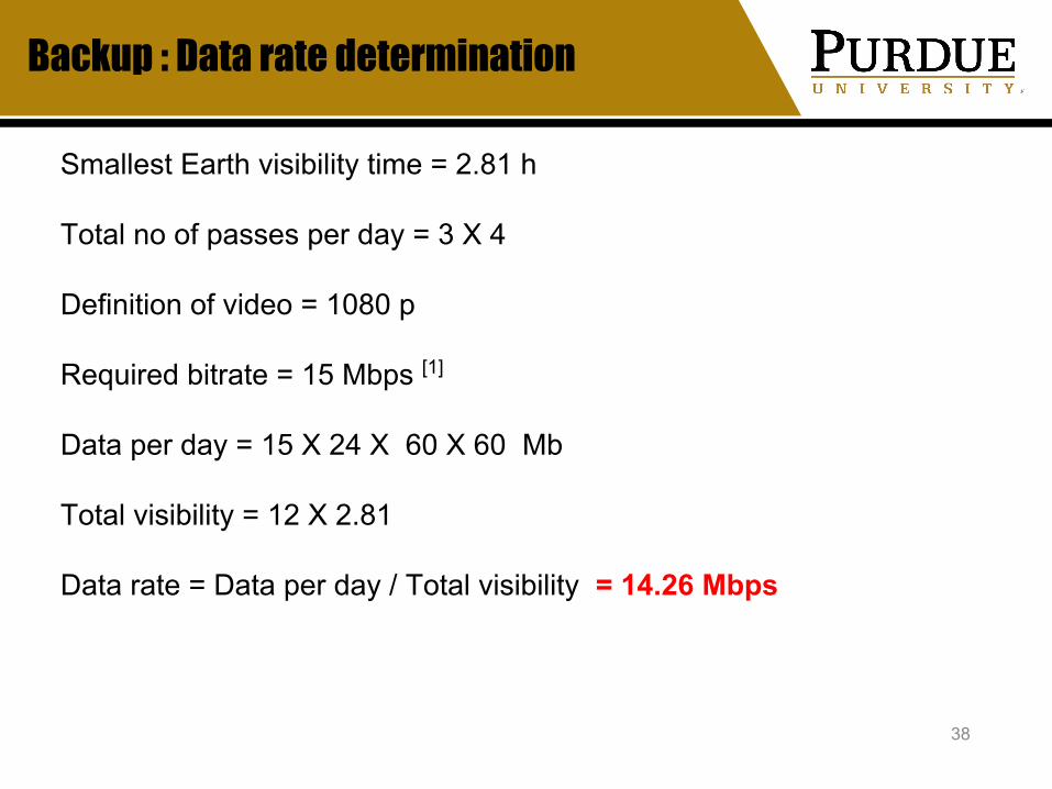
Backup : Data rate determination
Smallest Earth visibility time = 2.81 h Total no of passes per day = 3 X 4 Definition of video = 1080 p
Required bitrate = 15 Mbps [1]
Data per day = 15 X 24 X 60 X 60 Mb
Total visibility = 12 X 2.81
Data rate = Data per day / Total visibility = 14.26 Mbps

Backup : Reasoning for frequency selection
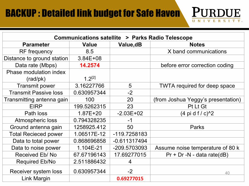
BACKUP : Detailed link budget for Safe Haven
40
Communications satellite > Parks Radio Telescope Parameter Value Value,dB Notes
RF frequency 8.5 X band communications Distance to ground station 3.84E+08
Data rate (Mbps) 14.2574 before error correction coding Phase modulation index
(rad/pk) 1.2[2] Transmit power 3.16227766 5 TWTA required for deep space
Transmit Passive loss 0.630957344 -2 Transmitting antenna gain 100 20 (from Joshua Yeggy’s presentation)
EIRP 199.5262315 23 Pt Lt Gt Path loss 1.87E+20 -2.03E+02 (4 pi d f / c)^2
Atmospheric loss 0.794328235 -1 Ground antenna gain 1258925.412 50 ParksTotal Recieced power 1.06517E-12 -119.7258183
Data to total power 0.868696858 -0.611317494 Data to noise power 1.104E-21 -209.5703093 Assume noise temperature of 80 k
Received Eb/ No 67.67196143 17.69277015 Pr + Dr -N - data rate(dB)Required Eb/No 2.511886432 4
Receiver system loss 0.630957344 -2 Link Margin 0.69277015

BACKUP : Detailed link budget for Communication Satellite
41
Communications satellite > Parks Radio Telescope Parameter Value Value,dB Notes
RF frequency 8.5 X band communications Distance to ground station 3.84E+08
Data rate (Mbps) 14.2574 before error correction coding Phase modulation index
(rad/pk) 1.2[2] Transmit power 3.16227766 5 TWTA required for deep space
Transmit Passive loss 0.630957344 -2 Transmitting antenna gain 100 25 (from Joshua Yeggy’s presentation)
EIRP 199.5262315 23 Pt Lt Gt Path loss 1.87E+20 -2.03E+02 (4 pi d f / c)^2
Atmospheric loss 0.794328235 -1 Ground antenna gain 1258925.412 50 ParksTotal Recieced power 1.06517E-12 -119.7258183
Data to total power 0.868696858 -0.611317494 Data to noise power 1.104E-21 -209.5703093 Assume noise temperature of 80 k
Received Eb/ No 67.67196143 17.69277015 Pr + Dr -N - data rate(dB)Required Eb/No 2.511886432 4
Receiver system loss 0.630957344 -2 Link Margin 5.70

42
Backup : Antenna diameter and beamwidth calculation
Antenna Diameter – antenna gain equation[4]
G = Gain in dBK = Efficiency (taken as 50%)D = Antenna diameter (m)λ = Wavelength (m)
Antenna Diameter – antenna beamwidth equation [4]
D = Antenna diameter (m)λ = Wavelength (m)

43
Backup : Matlab code

44
Backup : Matlab code

45
Backup : Matlab code
46
Backup : Matlab code
47
Backup : Matlab code

48
Backup : Matlab code

49
Backup : Matlab code

50
Backup : Matlab code

References
51
[1] Understanding video bitrates, encoding.com
[2] Space mission analysis and design, James R. Wertz
[3] European Space Agency, https://www.esa.int
[4] Parabolic Reflector Antenna Gain,https://www.electronics-notes.com
Human Factors Supplies and Storage Requirements
Sandra BonillaHuman Factors
Resource StorageJanuary 31, 2019
52
53
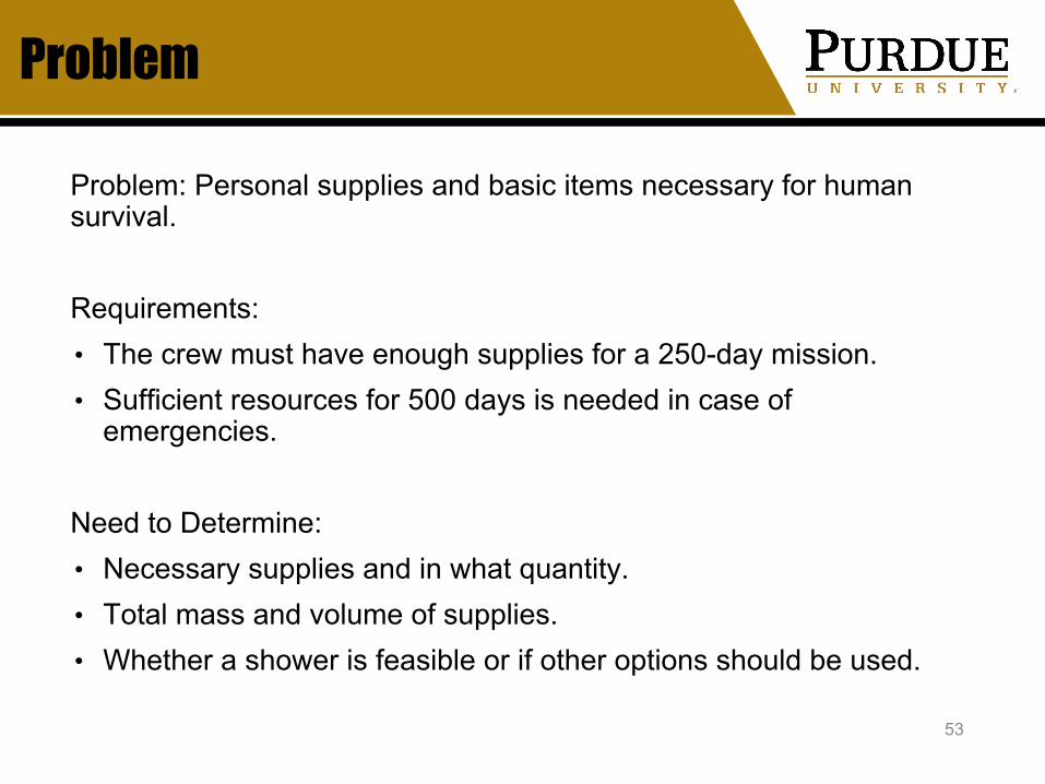
Problem
Problem: Personal supplies and basic items necessary for human survival.
Requirements:• The crew must have enough supplies for a 250-day mission. • Sufficient resources for 500 days is needed in case of
emergencies.
Need to Determine:• Necessary supplies and in what quantity.• Total mass and volume of supplies.• Whether a shower is feasible or if other options should be used.
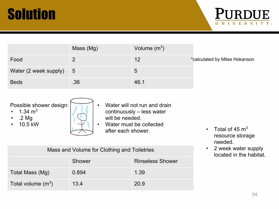
Solution
54
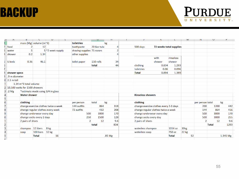
Mass (Mg) Volume (m3)
Food 2 12
Water (2 week supply) 5 5
Beds .36 46.1
*calculated by Miles Hokanson
Possible shower design:• 1.34 m3
• .2 Mg• 10.5 kW
Mass and Volume for Clothing and Toiletries
Shower Rinseless Shower
Total Mass (Mg) 0.894 1.39
Total volume (m3) 13.4 20.9
• Water will not run and drain continuously – less water will be needed.
• Water must be collected after each shower. • Total of 45 m3
resource storage needed.
• 2 week water supply located in the habitat.
BACKUP
55

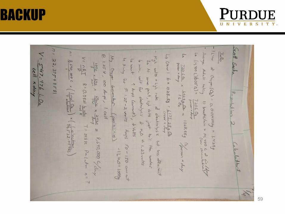
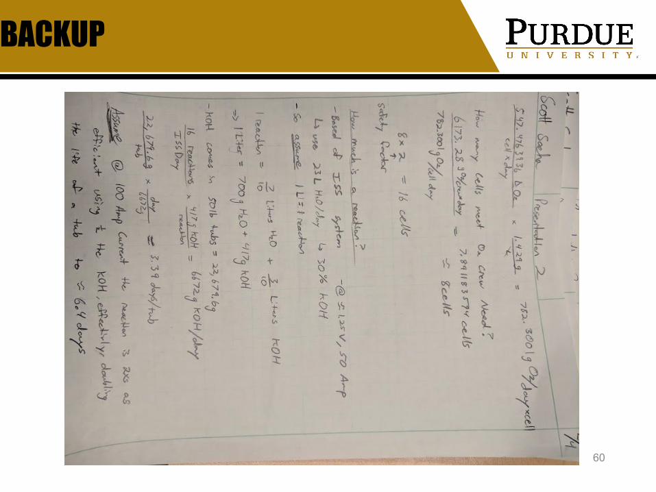
Moon Base Oxygen Generation
Scott SachaHuman FactorsGroup Leader
January 31, 2019
56
57
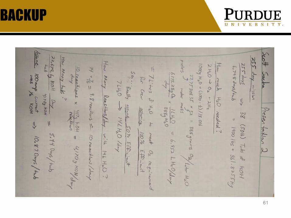
Problem: Oxygen Supplies-Moon Base
• Requirements: 6.1732 kg Oxygen/day (O2)
• Discover• Pros: Awesome we just need to capture it!• Cons: No air/Not possible
• Bring• Pros: We can breathe!• Cons: Storage uses space and mass on
launches, limited time usage.
• Create• Pros: Long lasting survivable method.• Cons: Need materials and energy.

58
Solution: Moon Base Electrolysis System
(255 Days)Power
(kW/day)Mass (kg)
Volume (m3)
Cost (USD) Notes
Water N/A 3570 3.57 0Assume water =
pure
KOH N/A 544.3108 0.454249 3072 N/A
Solar 3 UNKNOWN UNKNOWN 0Use disc. rover
power sys.
Battery 3 216 0.0943 14001.25V, 100 Amp
(parallel)
BACKUP
59
BACKUP
60
BACKUP
61

BACKUP
62

BACKUP
63
[1] Human Research Program Education and Outreach, “Oxygen Generator System,” MATH AND SCIENCE @ WORK. [Online]. Available: https://www.nasa.gov/pdf/570242main_OxygenGen_CHEM_ED.pdf. [Accessed: 16-Jan-2019].
[2] CR Scientific LLC, “Electrolysis Experiments,” CR Scientific: Electrolysis Experiments - Introduction. [Online]. Available: http://www.crscientific.com/electrolysis.html. [Accessed: 16-Jan-2019].
[3] W. C. Adams, “Measurement of Breathing Rate and Volume in Routinely Performed Activites,” California Environmental Protection Agency, Aug-1994. [Online]. Available: https://www.arb.ca.gov/research/resnotes/notes/94-11.htm. [Accessed: 16-Jan-2019].
[4] [email protected], m. (2019). Electrolysis of water. [online] Www1.lsbu.ac.uk. Available at: http://www1.lsbu.ac.uk/water/electrolysis.html [Accessed 30 Jan. 2019].
Delta-V Budget for Ice Shipment on Lunar/Depot Round Trip
Cody HawkinsMission Design Group Leader
Martian Transport / Habitat / Landing & Deployment / Resource StorageJanuary 31, 2019
64

65
Problem
- Requirements- Reusable vehicle must ferry ice
from surface to prop. depot- Ice delivery must be net positive
- Assumptions- Impulsive maneuvers- 2% reserve for ΔV- 6.68° inclination from Earth-Moon
plane to Moon equator
- Determine- ΔV requirements by site- Best site from ΔV perspective
Site Latitude (°)
Shackleton 89.9° S
Sverdrup 88.5° S
Rozhdestvenskiy 82.2° N
Solution
66
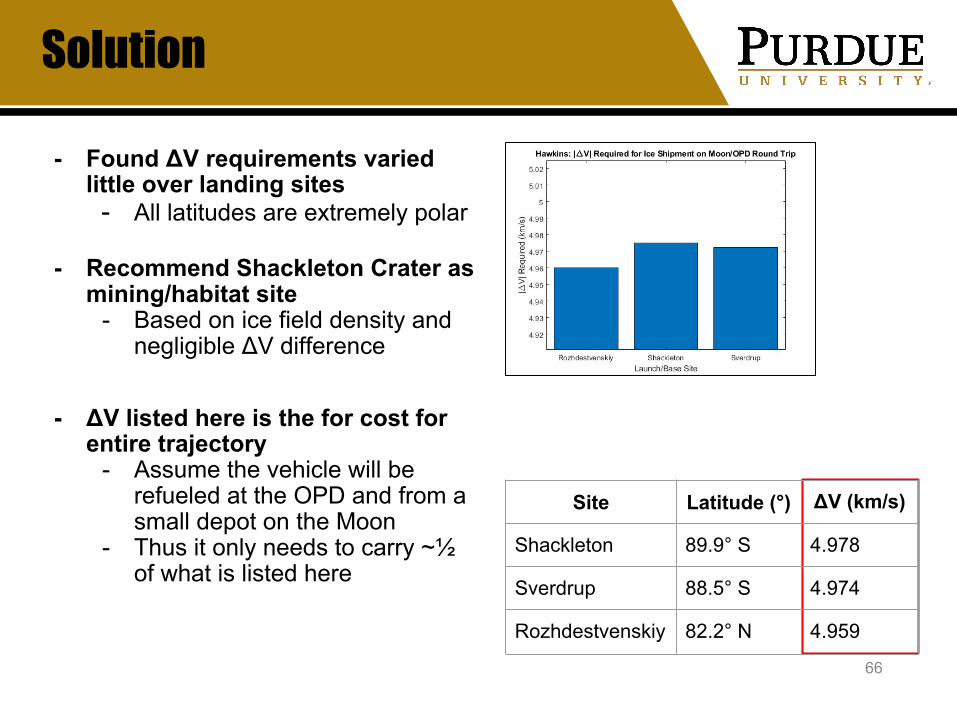
- Found ΔV requirements varied little over landing sites
- All latitudes are extremely polar
- Recommend Shackleton Crater as mining/habitat site
- Based on ice field density and negligible ΔV difference
- ΔV listed here is the for cost for entire trajectory
- Assume the vehicle will be refueled at the OPD and from a small depot on the Moon
- Thus it only needs to carry ~½ of what is listed here
Site Latitude (°) ΔV (km/s)
Shackleton 89.9° S 4.978
Sverdrup 88.5° S 4.974
Rozhdestvenskiy 82.2° N 4.959

BACKUP
67
Moon axis
Moon equator
Earth axis
Earth equator
Ecliptic plane
Earth Moon plane
6.68° obliquity
23.44° obliquity
Conclusion: need to reach 6.68° inclination relative to lunar equatorial plane for intercept with L1
- Change plane as far out as possible
L1

BACKUP
68
Step Description Avg. ΔV (km/s)
1 Launch to circular LLO 1.63
2 Transfer from circular LLO to L1
0.64
3 Plane change at L1/apoapsis 0.095
4 Stop at L1 0.072
5 Transfer from L1 to LLO 0.072
6 Reverse plane change at L1/apoapsis
0.095
7 Circular LLO capture 0.64
8 Enter descent arc 0.021
9 Propulsive landing 1.69
TOTAL 4.955
BACKUP
69
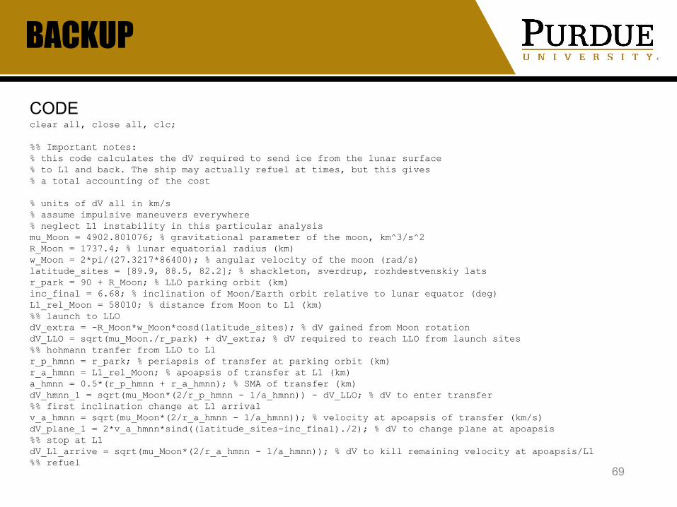
CODEclear all, close all, clc;
%% Important notes:% this code calculates the dV required to send ice from the lunar surface% to L1 and back. The ship may actually refuel at times, but this gives% a total accounting of the cost
% units of dV all in km/s% assume impulsive maneuvers everywhere% neglect L1 instability in this particular analysismu_Moon = 4902.801076; % gravitational parameter of the moon, km^3/s^2R_Moon = 1737.4; % lunar equatorial radius (km)w_Moon = 2*pi/(27.3217*86400); % angular velocity of the moon (rad/s)latitude_sites = [89.9, 88.5, 82.2]; % shackleton, sverdrup, rozhdestvenskiy latsr_park = 90 + R_Moon; % LLO parking orbit (km)inc_final = 6.68; % inclination of Moon/Earth orbit relative to lunar equator (deg)L1_rel_Moon = 58010; % distance from Moon to L1 (km)%% launch to LLOdV_extra = -R_Moon*w_Moon*cosd(latitude_sites); % dV gained from Moon rotationdV_LLO = sqrt(mu_Moon./r_park) + dV_extra; % dV required to reach LLO from launch sites%% hohmann tranfer from LLO to L1 r_p_hmnn = r_park; % periapsis of transfer at parking orbit (km)r_a_hmnn = L1_rel_Moon; % apoapsis of transfer at L1 (km)a_hmnn = 0.5*(r_p_hmnn + r_a_hmnn); % SMA of transfer (km)dV_hmnn_1 = sqrt(mu_Moon*(2/r_p_hmnn - 1/a_hmnn)) - dV_LLO; % dV to enter transfer%% first inclination change at L1 arrivalv_a_hmnn = sqrt(mu_Moon*(2/r_a_hmnn - 1/a_hmnn)); % velocity at apoapsis of transfer (km/s)dV_plane_1 = 2*v_a_hmnn*sind((latitude_sites-inc_final)./2); % dV to change plane at apoapsis%% stop at L1dV_L1_arrive = sqrt(mu_Moon*(2/r_a_hmnn - 1/a_hmnn)); % dV to kill remaining velocity at apoapsis/L1%% refuel
BACKUP
70
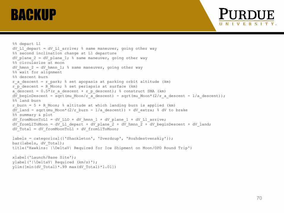
%% depart L1dV_L1_depart = dV_L1_arrive; % same maneuver, going other way%% second inclination change at L1 departuredV_plane_2 = dV_plane_1; % same maneuver, going other way%% circularize at moondV_hmnn_2 = dV_hmnn_1; % same maneuver, going other way%% wait for alignment%% descent burnr_a_descent = r_park; % set apopasis at parking orbit altitude (km)r_p_descent = R_Moon; % set periapsis at surface (km)a_descent = 0.5*(r_a_descent + r_p_descent); % construct SMA (km)dV_beginDescent = sqrt(mu_Moon/r_a_descent) - sqrt(mu_Moon*(2/r_a_descent - 1/a_descent));%% land burnr_burn = 5 + R_Moon; % altitude at which landing burn is applied (km)dV_land = sqrt(mu_Moon*(2/r_burn - 1/a_descent)) + dV_extra; % dV to brake%% summary & plotdV_fromMoonToL1 = dV_LLO + dV_hmnn_1 + dV_plane_1 + dV_L1_arrive;dV_fromL1ToMoon = dV_L1_depart + dV_plane_2 + dV_hmnn_2 + dV_beginDescent + dV_land;dV_Total = dV_fromMoonToL1 + dV_fromL1ToMoon;
labels = categorical({'Shackleton', 'Sverdrup', 'Rozhdestvenskiy'});bar(labels, dV_Total);title('Hawkins: |\DeltaV| Required for Ice Shipment on Moon/OPD Round Trip')
xlabel('Launch/Base Site');ylabel('|\DeltaV| Required (km/s)');ylim([min(dV_Total)*.99 max(dV_Total)*1.01])

Cislunar Vehicle Departures and Arrivals
Matthew WardaMission Design
Cislunar & Landing Vehicle Trajectory DesignJanuary 31, 2019

Problem
● Requirements○ Vehicle must navigate between the Earth and Moon○ Must be able to access Lagrangian point L1 or L2 from low
lunar orbit (LLO)○ Minimal ΔV necessities for transfer orbits○ Preferably low time-of-flight (TOF) values
● Assumptions○ Impulsive maneuvers○ Centrobaric and symmetrical bodies○ Isolated system consisting of the Earth, Moon, and Sun
● Need to Determine○ Departure and arrival locations from the Earth and Moon○ ΔV and TOF comparisons between transfer options

Solution
Transfer Angle ΔV (km/s) ΔV + 2% margin of error (km/s) TOF (Earth days)
15° 13.320 13.586 4.885
30° 12.397 12.645 4.892
60° 10.445 10.654 4.917
90° 8.418 8.586 4.950
120° 6.426 6.555 4.983
150° 4.714 4.808 5.006
180° 3.930 4.009 5.015
Lagrangian Point ΔV (km/s) ΔV + 5% margin of error (km/s) TOF (Earth days)
L1 0.7147 0.7504 2.687
L2 0.7111 0.7466 3.136
Transfers from 300 km Earth orbit to 90 km Moon
orbit
Transfers from 90 km Moon orbit
to Lagrangian
points
BACKUP

BACKUP
BACKUP

BACKUP
● References
○ Cornish, N. J. (2019, January 14). What is a Lagrange Point? | Solar System Exploration: NASA Science. Retrieved January 26, 2019, from https://solarsystem.nasa.gov/resources/754/what-is-a-lagrange-point/
○ Howell, E. (2017, August 21). Lagrange Points: Parking Places in Space. Retrieved January 27, 2019, from https://www.space.com/30302-lagrange-points.html
○ Williams, D. R. (2018, July 18). Planetary Fact Sheet. Retrieved January 27, 2019, from https://nssdc.gsfc.nasa.gov/planetary/factsheet/
Scout Rover Travel Power Required
Myles HomanPower and Thermal
Scout RoversJanuary 31, 2019
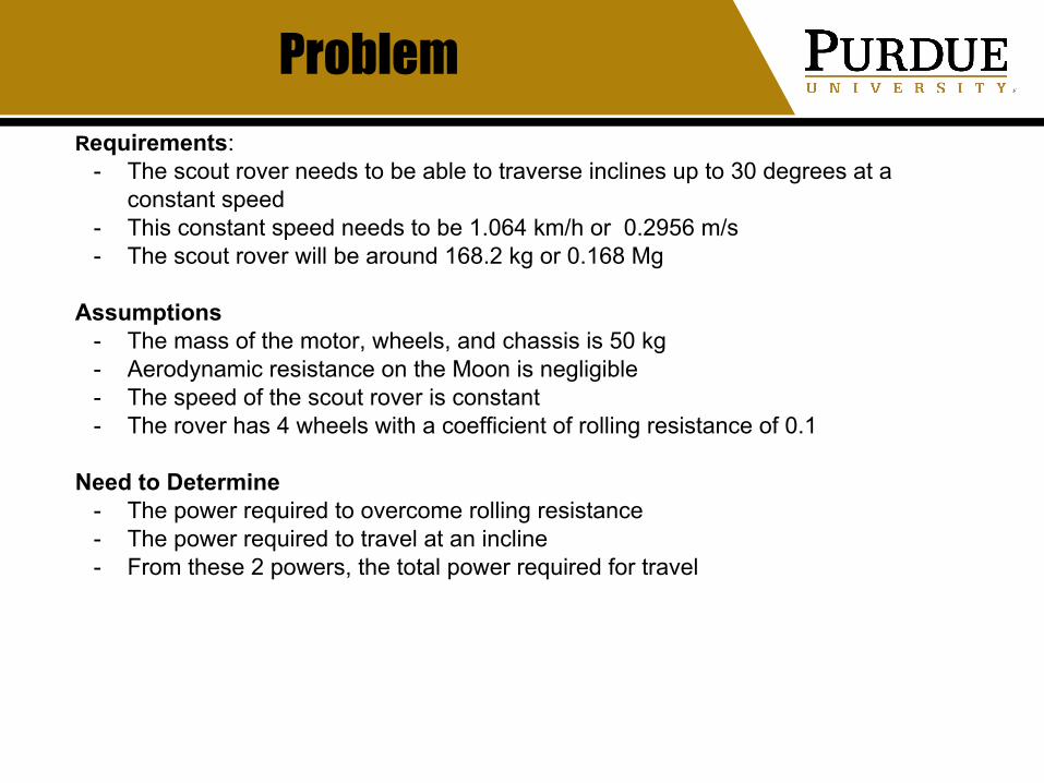
ProblemRequirements:
- The scout rover needs to be able to traverse inclines up to 30 degrees at a constant speed
- This constant speed needs to be 1.064 km/h or 0.2956 m/s- The scout rover will be around 168.2 kg or 0.168 Mg
Assumptions- The mass of the motor, wheels, and chassis is 50 kg- Aerodynamic resistance on the Moon is negligible- The speed of the scout rover is constant- The rover has 4 wheels with a coefficient of rolling resistance of 0.1
Need to Determine- The power required to overcome rolling resistance- The power required to travel at an incline- From these 2 powers, the total power required for travel
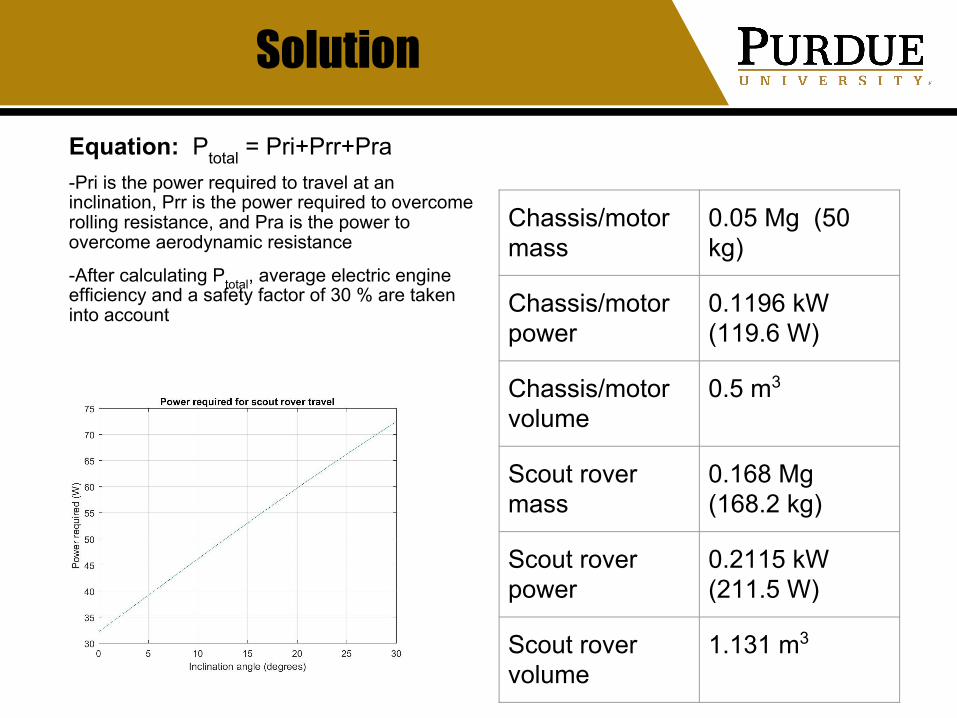
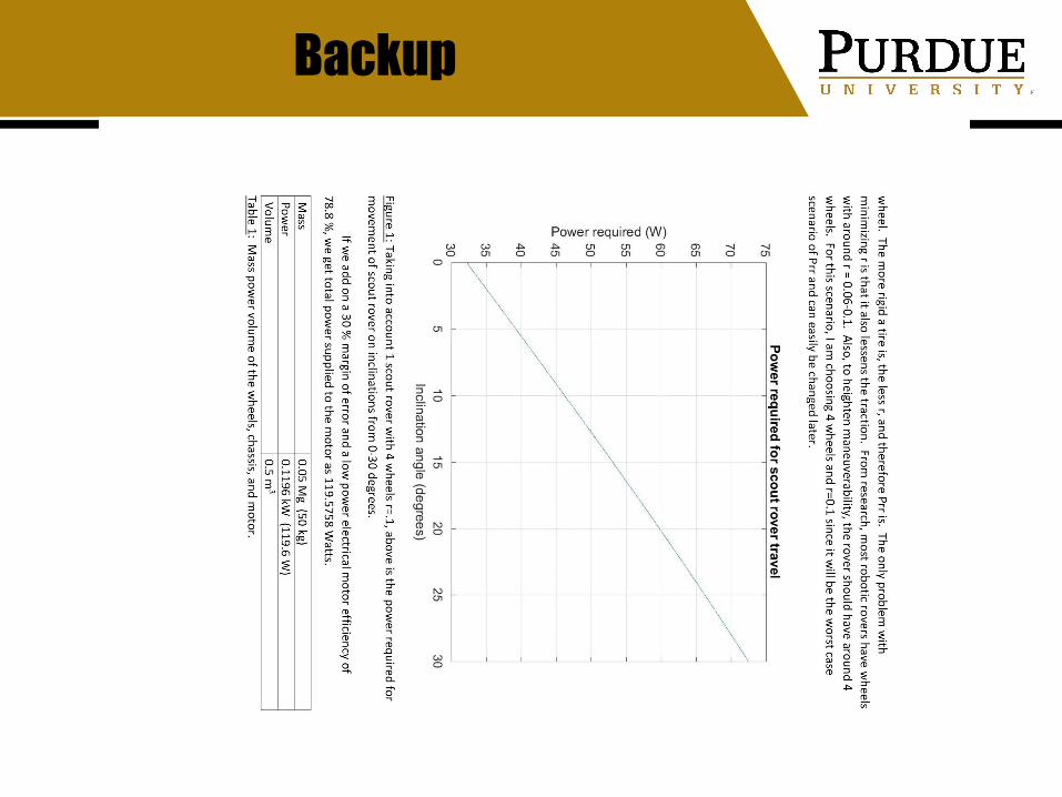
SolutionEquation: Ptotal = Pri+Prr+Pra -Pri is the power required to travel at an inclination, Prr is the power required to overcome rolling resistance, and Pra is the power to overcome aerodynamic resistance
-After calculating Ptotal, average electric engine efficiency and a safety factor of 30 % are taken into account
Chassis/motor mass
0.05 Mg (50 kg)
Chassis/motor power
0.1196 kW (119.6 W)
Chassis/motor volume
0.5 m3
Scout rover mass
0.168 Mg (168.2 kg)
Scout rover power
0.2115 kW (211.5 W)
Scout rover volume
1.131 m3

Backup
Backup

Backup

References
[1] “Electrical Motor Efficiency” Retrieved from https://www.engineeringtoolbox.com/electrical-motor-efficiency-d_655.html
[2] “Power to Move a Person” Retrieved from https://www.xootr.com/power-to-move-a-person.html
[3] Apostolopoulos, Dimitrios & Wagner, Michael & Leger, Chris & Jones, Jack. (2005). Experimental Characterization of a Robotic Inflatable Wheel.

Communication Satellites and Safe Haven
Alycia McEachenPower and Thermal Systems
January 17, 2019
85
Problem
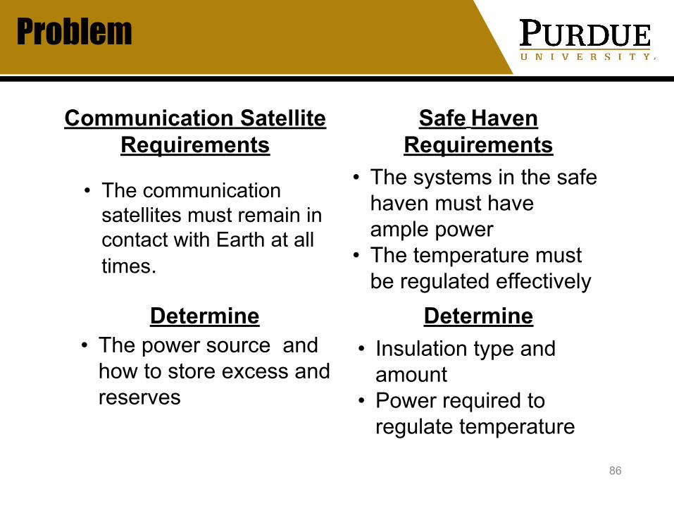
86
• The communication satellites must remain in contact with Earth at all times.
• The systems in the safe haven must have ample power
• The temperature must be regulated effectively
Communication Satellite Requirements
Safe Haven Requirements
• The power source and how to store excess and reserves
Determine Determine• Insulation type and
amount• Power required to
regulate temperature
Solution
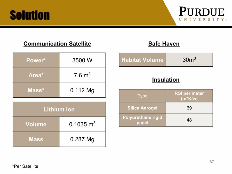
87
Communication Satellite
*Per Satellite
Safe Haven
Power* 3500 W
Area* 7.6 m2
Mass* 0.112 Mg
Lithium Ion
Volume 0.1035 m3
Mass 0.287 Mg
Habitat Volume 30m3
Insulation
Type RSI per meter (m*K/w)
Silica Aerogel 69
Polyurethane rigid panel 48
BACKUP
• Energy density of solar radiation at moon is similar to energy density on earth- 1368w/m2
88
Assumptions
BACKUP
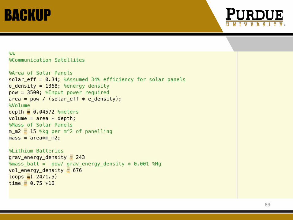
Screen Shot 2019-01-31 at 12.08.33 AM
89

BACKUP
90
“Common Sizes of Solar Panels,” Brightstar SolarAvailable: http://brightstarsolar.net/common-sizes-of-solar-panels/.
“From the Lab to the Marketplace,” LBNL - KEVLAR--CLUE #1Available: https://www2.lbl.gov/Science-Articles/Archive/aerogel-insulation.html.
“Insulation,” Department of EnergyAvailable: https://www.energy.gov/energysaver/weatherize/insulation.
“Lithium Ion,” PanasonicAvailable: https://na.industrial.panasonic.com/sites/default/pidsa/files/ncr18650b.pdf.
Simone, “Is my roof suitable for solar panels (and what is the weight of a solar panel)?,” SunmetrixAvailable: https://sunmetrix.com/is-my-roof-suitable-for-solar-panels-and-what-is-the-weight-of-a-solar-panel/.
“Staying Cool on the ISS,” NASAAvailable: https://science.nasa.gov/science-news/science-at-nasa/2001/ast21mar_1.
References

BACKUP
91

Lunar Ascent/Descent Vehicle Feasibility
Ryan DelahuntyPropulsion
Lunar Ascent/Descent VehicleJanuary 31, 2019
92
Problem:
93
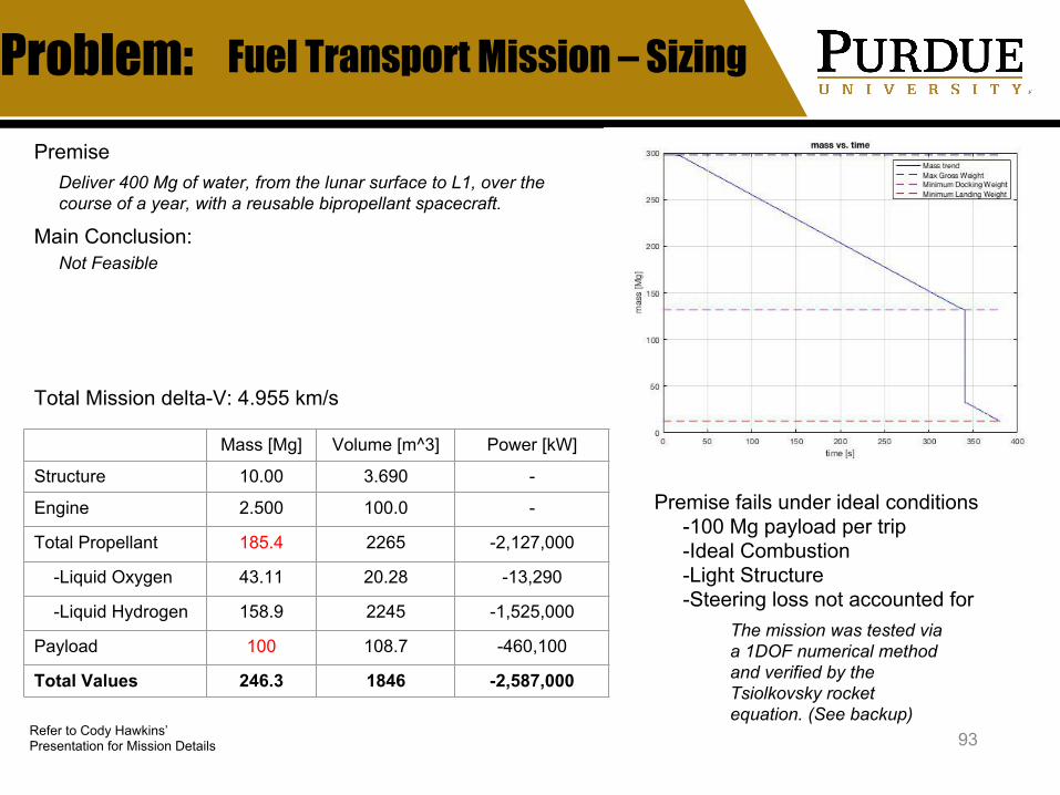
Mass [Mg] Volume [m^3] Power [kW]
Structure 10.00 3.690 -
Engine 2.500 100.0 -
Total Propellant 185.4 2265 -2,127,000
-Liquid Oxygen 43.11 20.28 -13,290
-Liquid Hydrogen 158.9 2245 -1,525,000
Payload 100 108.7 -460,100
Total Values 246.3 1846 -2,587,000
Refer to Cody Hawkins’ Presentation for Mission Details
Fuel Transport Mission – Sizing
Main Conclusion:
Total Mission delta-V: 4.955 km/s
Premise fails under ideal conditions -100 Mg payload per trip -Ideal Combustion -Light Structure -Steering loss not accounted for
Deliver 400 Mg of water, from the lunar surface to L1, over the course of a year, with a reusable bipropellant spacecraft.
The mission was tested via a 1DOF numerical method and verified by the Tsiolkovsky rocket equation. (See backup)
Premise
Not Feasible

Recommendation: Lunar Fuel Depot
94
Lunar Fuel Depot
Production Increase
-Adds design challenges to Mars Transport Vehicle-Simplifies overall engineering challenges
-Also requires a production output increase
Two Potential Solutions
-Increase would need to be by orders of magnitude-Inherently inefficient to deliver water to orbit with
traditional rocket propulsion

95
BACKUP
96
BACKUP

97
BACKUP
98
BACKUP

99
BACKUP

100
Backup

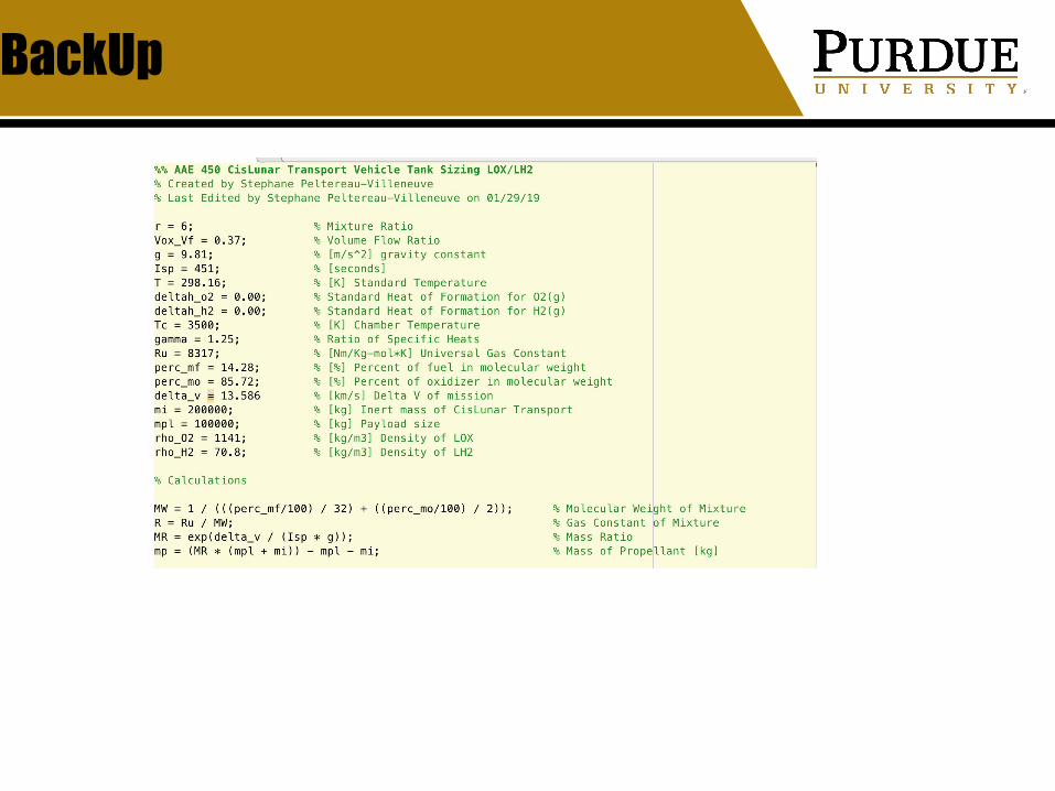
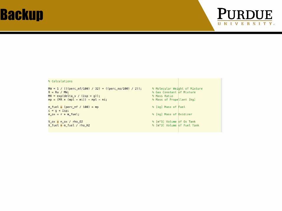
CisLunar Transport Vehicle
Stephane Peltereau-VilleneuvePropulsion
Cislunar Transport Vehicle | Orbital Fuel DepotJanuary 31, 2019
101
102
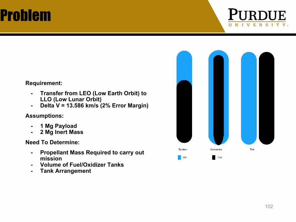
Problem
Requirement:
- Transfer from LEO (Low Earth Orbit) to LLO (Low Lunar Orbit)
- Delta V = 13.586 km/s (2% Error Margin)
Assumptions:
- 1 Mg Payload- 2 Mg Inert Mass
Need To Determine:
- Propellant Mass Required to carry out mission
- Volume of Fuel/Oxidizer Tanks- Tank Arrangement
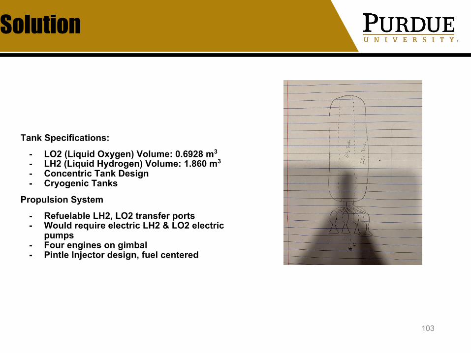
Solution
103
Tank Specifications:
- LO2 (Liquid Oxygen) Volume: 0.6928 m3 - LH2 (Liquid Hydrogen) Volume: 1.860 m3
- Concentric Tank Design- Cryogenic Tanks
Propulsion System
- Refuelable LH2, LO2 transfer ports - Would require electric LH2 & LO2 electric
pumps- Four engines on gimbal- Pintle Injector design, fuel centered
BackUp
Backup

References
106
Sutton, G. P., and Biblarz, O., Rocket propulsion elements, Hoboken (N.Y.): Wiley., 2017.
Heister, S. D., Anderson, W. E., Pourpoint, T., and Cassady, J., Rocket Propulsion., 2019.
Safe Haven Specific Science Payload Specifications
Harry LlamasScience
Safe HavenJanuary 31, 2019
107

108
Problem
Chief Scientific Factors Affecting Safe Haven Specifications:• Radiation Shielding• Emergency Food and Water Supplies
Adequate radiation shielding will be required to ensure Astronauts do not receive a dangerous level of radiation whilst seeking shelter within the safe haven. Since this is an emergency shelter it will not necessarily have the same level of radiation shielding as within the habitat
Whilst they are within the safe haven they will have to have an adequate food supply to survive for short lengths of time and possible evacuation back to Earth
H
r
Solution
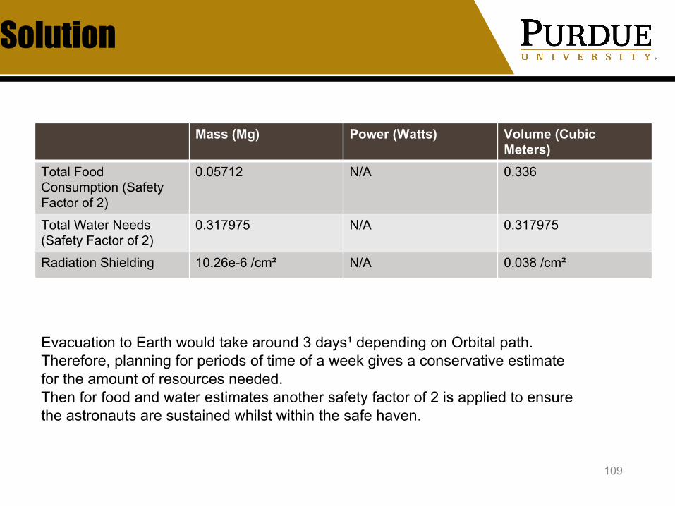
109
Mass (Mg) Power (Watts) Volume (Cubic Meters)
Total Food Consumption (Safety Factor of 2)
0.05712 N/A 0.336
Total Water Needs (Safety Factor of 2)
0.317975 N/A 0.317975
Radiation Shielding 10.26e-6 /cm² N/A 0.038 /cm²
Evacuation to Earth would take around 3 days¹ depending on Orbital path. Therefore, planning for periods of time of a week gives a conservative estimate for the amount of resources needed. Then for food and water estimates another safety factor of 2 is applied to ensure the astronauts are sustained whilst within the safe haven.

BACKUP
110
Total water needs of 6 man crew is around 6 gallons per day in an emergency situation² assuming astronauts will be drinking half a gallon per day and using another half gallon for personal hygiene. This would then mean for a weeks stay aboard the safe haven 42 Gallons would be required and then 84 Gallons giving a safety factor of 2 should more water be used or the stay be longer than expected. This equates to 317.975 litres.
Each Astronaut still needs to consume at least 2000 calories³ per day at a net mass of 3.6e-4 kg/calorie that would require at least 57.12 kg⁴ of food for a 2 week stay and at 2e-6 cubic metre per calorie that would give 0.336 cubic metres for a two week stay
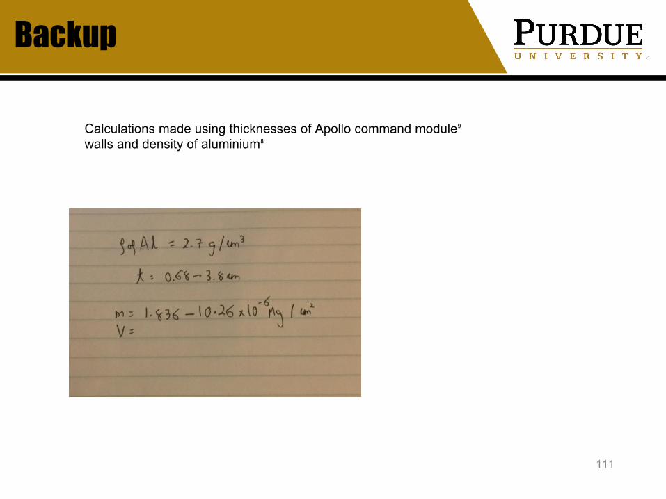
The maximum allowable radiation exposure of a person as denoted by the united states is 50 mSv and this applies for lunar missions of up to 180 days, so for the 7 days they might be living within the safe haven it would be important to ensure that they receive less than 1.94 mSv⁵ of radiation Estimates for the worst case during a solar particle event put the total radiation received in the lunar environment at around 1 Sv per year⁶ so approximately 19.16495551 mSv for the week long duration. This would have to be mitigated by radiation shielding. Commonly aluminium is used as the casing of spacecrafts⁷, this can only absorb half the radiation that hits it, this would still mean the astronauts are receiving a very high dose during this stay.
111
Backup
Calculations made using thicknesses of Apollo command module⁹ walls and density of aluminium⁸
112
References
1. https://nssdc.gsfc.nasa.gov/nmc/spacecraft/display.action?id=1969-059A
2. https://www.beprepared.com/blog/18680/much-water-store/3. https://www.nasa.gov/vision/earth/everydaylife/jamestown-ne
eds-fs.html.4. https://airandspace.si.edu/exhibitions/apollo-to-the-moon/onli
ne/astronaut-life/food-in-space.cfm5. https://en.wikipedia.org/wiki/Spaceflight_radiation_carcinoge
nesis#Current_permissible_exposure_limits6. http://adsabs.harvard.edu/abs/2012P%26SS...74...78R7. https://www.nasa.gov/audience/foreducators/5-8/features/F_
Shielding_Space_Rays.html8. https://www.google.com/search?q=density+of+aluminium&o
q=density+of+aluminium&aqs=chrome..69i57j0l5.5335j1j7&sourceid=chrome&ie=UTF-8
9. https://en.wikipedia.org/wiki/Apollo_command_and_service_module#Command_module_(CM)

Preliminary Science Laboratory Sizing and Equipment
Theo SorgGroup Lead, Science
Habitat, Fuel-Depot, Landing Site PrepJanuary 31, 2019
113
Problem: Habitat Laboratory
114
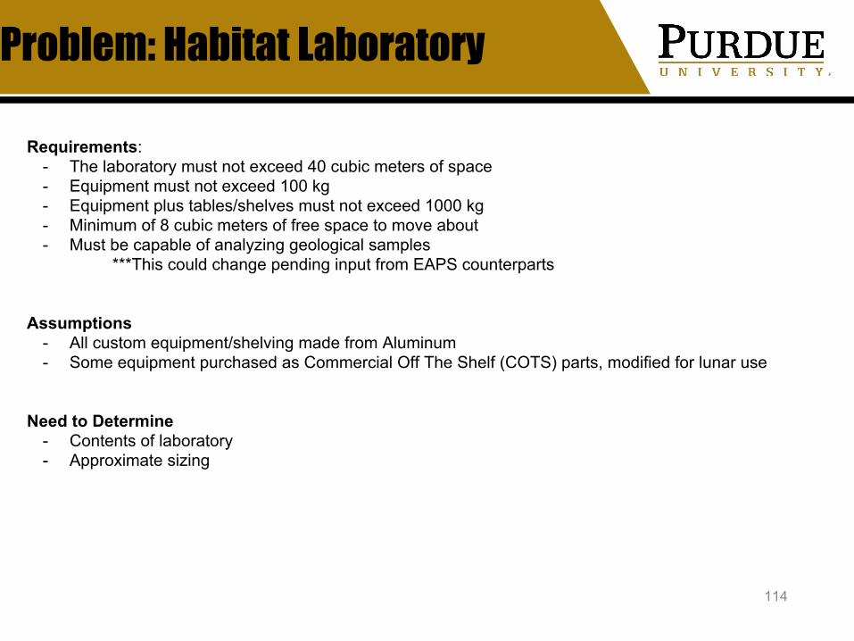
Requirements: - The laboratory must not exceed 40 cubic meters of space- Equipment must not exceed 100 kg- Equipment plus tables/shelves must not exceed 1000 kg- Minimum of 8 cubic meters of free space to move about- Must be capable of analyzing geological samples
***This could change pending input from EAPS counterparts
Assumptions- All custom equipment/shelving made from Aluminum- Some equipment purchased as Commercial Off The Shelf (COTS) parts, modified for lunar use
Need to Determine- Contents of laboratory- Approximate sizing

Totals- Mass (excluding surrounding structure): 740 kg- Power required for equipment: 720 Watts- Volume: 30 cubic meters
Equipment- Scales (2)- Hammers (2)- Chisels (full set)- Polarizing light microscope- Scanning Electron Microscope
Future Iterations- Adjustments in equipment per science objectives- Layout adjustments per human factors input- More accurate volume estimation and CAD
Solution
115
4 meters
3 meters
2.5 meters
BACKUP: Equipment
116
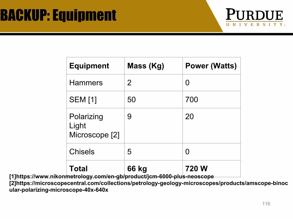
Equipment Mass (Kg) Power (Watts)
Hammers 2 0
SEM [1] 50 700
Polarizing Light Microscope [2]
9 20
Chisels 5 0
Total 66 kg 720 W[1]https://www.nikonmetrology.com/en-gb/product/jcm-6000-plus-neoscope[2]https://microscopecentral.com/collections/petrology-geology-microscopes/products/amscope-binocular-polarizing-microscope-40x-640x

BACKUP: Tables and Shelves
117

Mass Estimate of Scout Rovers/Demo Systems
Jack GreenStructures
Scout Rovers/Demonstration SystemsJanuary 31, 2019
118

Problem: Determine Mass of Scout Rovers
119
Requirements: - Safely handle a capacity of between 0.079 Mg and 0.104 Mg (based on Science Team estimates)- Successfully deal with launch, landing, and deployment
- Landing may require additional structural support- Radiation Protection
Previous Calculation Estimates:- Science payload mass : ~0.103 Mg- Science payload volume : ~1.64 m3
- Numbers from Science Team
Need to Determine...- Architectural mass including
- Radiation Shield- Structure and support
- Volume of rover material

Solution: Material Type and Shape
120
Radiation Protection- Polyethylene Shield
- Density: 0.96 g/cm3
- Thickness: 5 cm- Has about half the mass of equivalent
aluminum shield- Excellent at radiation absorption due to its high
hydrogen contentShield Shape
- Dome optimal for space and mass minimization
Rover Structure- Additional Mass of ~0.03 Mg
Future Iterations- CAD Design- More detailed power analysis
- (with help from power team)
Results:

Backup - Material Mass Comparison
121
- For Polyethylene
- For Kevlar

Backup - References
122
[1] https://science.nasa.gov/science-news/science-at-nasa/2005/08sep_radioactivemoon [2] https://www.space.com/24731-mars-radiation-curiosity-rover.html [3] https://www.space.com/21353-space-radiation-mars-mission-threat.html [4] https://www.thomasnet.com/articles/custom-manufacturing-fabricating/radiation-shielding-materials [5] https://www.nasa.gov/vision/space/travelinginspace/radiation_shielding.html [6] https://www.nature.com/articles/s41598-017-01707-2.pdf [7] https://mars.nasa.gov/mer/technology/bb_power.html


