© Copyright QinetiQ Limited 2012
UNCLASSIFIED
1
GPS TSPI for Ultra High Dynamics
Use of GPS L1/L2/L5 Signals for TSPI
ITEA Test Instrumentation Workshop, May 15th – 18th 2012
For further information please contact
Tony Pratt: [email protected]
Alex Macaulay: [email protected]
Nick Cooper: [email protected]
Unit 1, Highfield Parc
Highfield Road, Oakley
Bedfordshire MK43 7TA
United Kingdom
Batch of 10 off Q20 HD GPS Modules Being
Pick and Place Populated During Manufacture
DISTRIBUTION STATEMENT A. Approved for public release;
distribution is unlimited

© Copyright QinetiQ Limited 2012
UNCLASSIFIED
2
Contents
Motivation
GPS Solution
GPS Signals Evolution
Architecture of Receiver
• Signal Conditioning
• Search, Acquisition and Tracking
• Measurements and processing
Performance Simulation
Performance Test Results

© Copyright QinetiQ Limited 2012
UNCLASSIFIED
3 3
Motivation
© Copyright QinetiQ Limited 2012
UNCLASSIFIED
4
Motivation
Test and Evaluation Applications for Advanced Weapons
• New class of high energy kinetic weapons
− Distinguishing characteristics
− High dynamics envelope: acceleration ~500g; velocity ~5km/s; control range safety zone
• New classes of T&E measurement requirements
− GPS and coupled (MEMS) IMU
− Accuracy improvement, Support in ‘difficult’ GPS areas (urban warfare)
• High accuracy TSPI results
− Moderate to low dynamics
− End game scoring - ~10cms
• Tactical GPS will be subject to intentional denial in areas of military operation
− Requirement to test for effects on weapons systems
− L5 signals provide independent navigation grid for T&E
− Jamming causes unpredictable behaviour – see next slide

© Copyright QinetiQ Limited 2012
UNCLASSIFIED
5
Observed Effects of Jamming
Coverage of GPS jamming unit; 25m above ground level, maximum power 1.58W ERP
Ship steering course in blue
• Left track (no jamming)
• Right track – GPS L1 locations reported with jammer switched on
− Red dots are speeds > 100kts
Images courtesy of Dstl
© Copyright QinetiQ Limited 2012
UNCLASSIFIED
6 6
GPS Solution & Signal Evolution

© Copyright QinetiQ Limited 2012
UNCLASSIFIED
7
T&E Solutions using 3 Frequency GPS
GPS Broadcasts on 3 Frequencies
• L1 1575.42 MHz (154 x 10.23 MHz) – P(Y) code, C/A code
• L2 1227.60 MHz (120 x 10.23 MHz) – P(Y) code + CM, CL code, broadcast from 10 SV’s
• L5 1176.45MHz (115x10.23MHz) – L5I + L5Q, broadcast from 2 SV’s
− L5 (civil) signals on Block IIF SV’s
L1, L2, L5 – offer greater range of T&E performance options
• L1: - Rapid time to acquisition & fix; high dynamics envelope ~300g+
− Long code wavelength (CA = 293m); short code of 1ms, range ambiguity (293 km)
• L2: - New civil signals; L2CM, L2CL
− Longer code wavelength (L2C = 586m), potential for dynamics ~500g LOS
− Codes are 20ms & 1.5 sec, no range ambiguity, greater difficulty in acquisition (esp. CL)
• L5: - Operates in aeronautical safety of life band (ITU protected)
− Short code wavelength (code = 29.3m), 10.23Mcps code rate - same as P(Y)
− Provides independent low dynamic navigation
− T&E application used for L1/L2 performance assessment during jamming conditions
© Copyright QinetiQ Limited 2012
UNCLASSIFIED
8
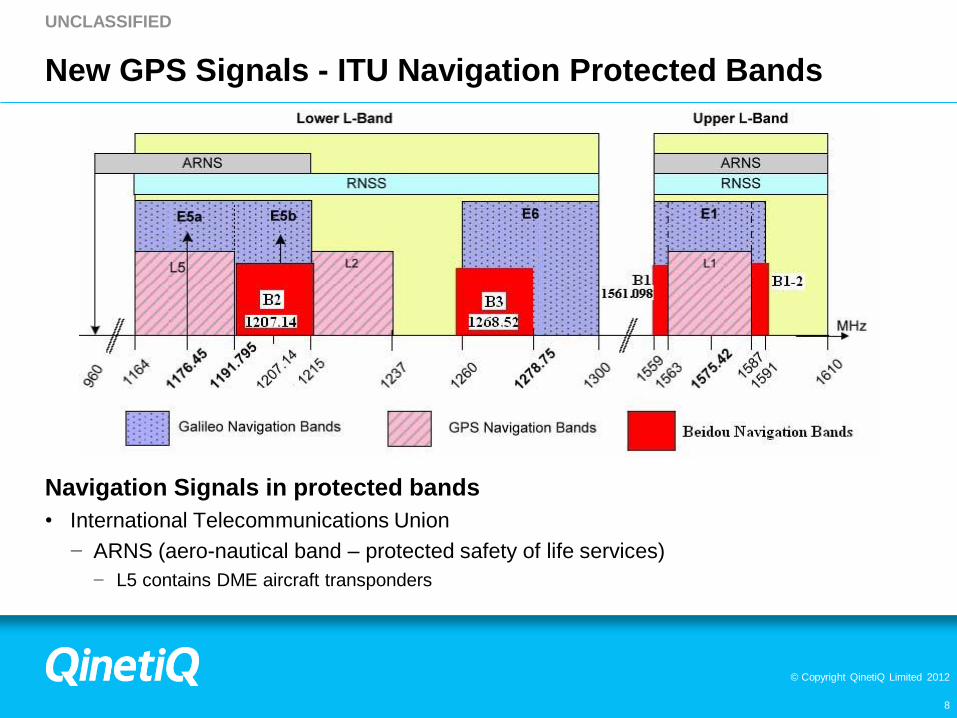
New GPS Signals - ITU Navigation Protected Bands
Navigation Signals in protected bands
• International Telecommunications Union
− ARNS (aero-nautical band – protected safety of life services)
− L5 contains DME aircraft transponders
© Copyright QinetiQ Limited 2012
UNCLASSIFIED
9
UHD Basic Concepts
Three Frequency GPS Receiver
• Basic civil signal receiver avoiding use of military signals
− Military code wavelength requires use of IMU to support high dynamics (m=29.3m)
− Military codes are long (1 week) at 10,230 kchips/sec
− Limited (10dB) benefit against jamming (compared to C/A code)
Processing for fast Time To First Fix (TTFF)
• Direct data download from satellite too slow (30+sec)
− Typical requirement < 3sec
• Hybrid receiver mode
− Uses ground Reference Station includes GPS receiver resource
− Navigation Messages from visible satellites
− Establishes position estimate and GPS time solution
− Optionally measure and correct for satellite clock and ephemeris errors (differential mode)
• Solution computed in ground station
− Options for measurement combinations

© Copyright QinetiQ Limited 2012
UNCLASSIFIED
10
UHD Receiver Architecture
& Performance Simulation

© Copyright QinetiQ Limited 2012
UNCLASSIFIED
11
Main Developments in UHD
Three Frequency GPS Reception
Sustained or Improved TTFF
• Efficient use of hardware architecture to provide >1M acquisition channels
− Simultaneous frequency and code search algorithm
Multi-channel Tracking for all-in-view Satellites
• Every frequency/signal simultaneously tracked
• Hardware uses high speed multiplex technique
− Benefits from speed of current FPGA/ASIC switching circuits
− Reduces circuit area but not power consumption
Tracking Loop Design for Maximum Acceleration Dynamics
• Trades sensitivity for dynamics to limit of GPS capability
Hybrid Receiver Technique to Sustain sub-30 sec TTFF
− Accuracy improvements through DGPS possible

© Copyright QinetiQ Limited 2012
UNCLASSIFIED
12
Physical Breadboard
COTS Platform
• 2 FPGA with sufficient capacity
• 2 x Virtex 5 LX220 -2 (Xilinx)
− Signal conditioning and tracking; signal acquisition

© Copyright QinetiQ Limited 2012
UNCLASSIFIED
13
UHD System Architecture
System Architecture
• Separate channels for acquisition and tracking
− Acquisition requires 100,000’s channels to support short TTFA
− Tracking requires few physical channels dedicated to visible SV’s (~60 for 5 signals /SV)
− L1(1); L2(1); L5 (5)
• Signal conditioning
− Digital transversal filters to set bandwidth (allowing lower sample rates)
− Received signal samples are stored
− Acquisition based on analysis of stored data sample (eg 1ms for C/A code; 20ms for L2CM)
− Acquired signals referenced to common timebase
RF Processor
L1, L2, L5
Internal clock
Input
Frequency
Changing to
near
baseband
Input digital
filters
L1, L2, L5
Received Sample
Store
Acquisition Data Processor
Tracking Data Processor
Software Process
Management
Signal detection
Neuman-Hofman Code
detection
Data Transfer Acq-Track
Tracking loops

© Copyright QinetiQ Limited 2012
UNCLASSIFIED
14
Dynamic Envelope for Host Vehicle
Stresses the Receiver Measurement Circuits
− Satellite tracking lost if stress too large
• Tracking circuits experience 2 types of stress:
− Noise - mainly controlled by bandwidth and C/N0 levels
− Sources of dynamic stresses:
− host body - satellite motion resolved along line of sight (LOS) to satellite
• Dynamic stresses arise due to:
− During signal acquisition
− transients – imperfect match of estimated code delay and Doppler to actual
− Un-modeled motion (after acquisition)
− Tracking architecture holds vehicular motion states (such as position, velocity, etc)
− Stable states do not contribute to stress
− Host vehicle states are useful if stable for reasonable intervals
− Highly dependent on expected host vehicle trajectory
− Mainly controlled using 3rd order tracking loops
− Model position, velocity, acceleration states
© Copyright QinetiQ Limited 2012
UNCLASSIFIED
15
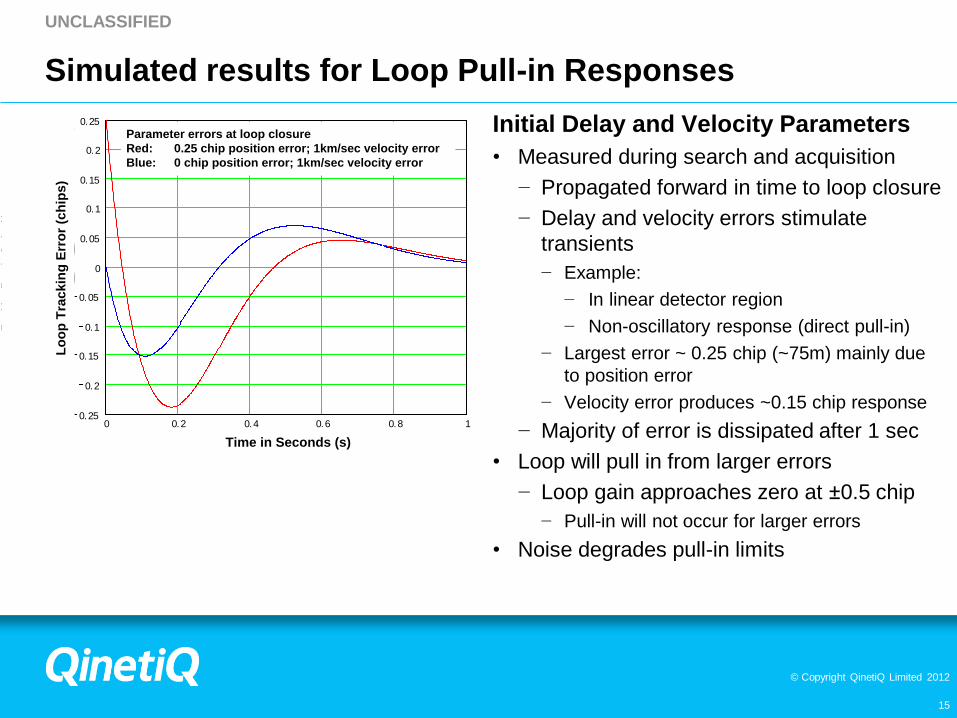
Simulated results for Loop Pull-in Responses
Initial Delay and Velocity Parameters
• Measured during search and acquisition
− Propagated forward in time to loop closure
− Delay and velocity errors stimulate
transients
− Example:
− In linear detector region
− Non-oscillatory response (direct pull-in)
− Largest error ~ 0.25 chip (~75m) mainly due
to position error
− Velocity error produces ~0.15 chip response
− Majority of error is dissipated after 1 sec
• Loop will pull in from larger errors
− Loop gain approaches zero at ±0.5 chip
− Pull-in will not occur for larger errors
• Noise degrades pull-in limits
0 0.2 0.4 0.6 0.8 10.25
0.2
0.15
0.1
0.05
0
0.05
0.1
0.15
0.2
0.25
Time in seconds
Tra
ck
ing
Err
or
in C
ode c
hip
s
0.25
0.25
U3j 0
dl3j
U1j 0
dl1j
1.00 j TTime in Seconds (s)
Lo
op
Tra
ck
ing
Err
or
(ch
ips
)
Parameter errors at loop closure
Red: 0.25 chip position error; 1km/sec velocity error
Blue: 0 chip position error; 1km/sec velocity error

© Copyright QinetiQ Limited 2012
UNCLASSIFIED
16
0 2 4 6 8 100.5
0.4
0.3
0.2
0.1
0
0.1
0.2
0.3
0.4
0.5
Time in seconds
Tra
ckin
g E
rro
r in
Co
de c
hip
s
0.5
0.5
U3j 0
dl3j
U4j 0
dl3j
10.00 j T
Pull-in Conditions:
Acceleration Error: 250g
Velocity Error: 1km/sec
Position Error: 73m
Time (seconds) after Loop Closure
Tra
ck
ing
Err
or
(Ch
ips
) a
fte
r lo
op
clo
su
re
Noise Response at Pull-in
Realization of Loop Response
− Results from simulation
• Combined response of:
− Noise input
− 250g acceleration step
− ¼ chip position error
− 1km/s LOS velocity error
• Balance between:
− Noise and dynamic stimuli
• See approach to critical error (½ sec)
− C/N0 ~ 23dB (red); 36dB (blue)
− Identical noise realization in simulation
− Generated from random number source
Loop near drop out

© Copyright QinetiQ Limited 2012
UNCLASSIFIED
17
Performance Tests and Results
© Copyright QinetiQ Limited 2012
UNCLASSIFIED
18
UHD GPS Testing
Verification and Validation Testing Carried Out
• Test cases defined based on User and System requirements
• Performed at QinetiQ and GWEF (Eglin AFB) facilities
Tests with Simulated RF Signals
• Provides repeatability, control, dynamics and truth data - common test scenarios
• QinetiQ: Spirent GSS8800
• GWEF: Spirent GSS7700
• Tested under dynamics
− acquisition and tracking performance
− position and velocity accuracy, carrier phase
Tests with Off-air Signals
• L1 (31 satellites), L2C (10 satellites)
− Combined L1/L2 antenna
• L5 insufficient satellites (2 only so far)

© Copyright QinetiQ Limited 2012
UNCLASSIFIED
19
UHD GPS Headline Achievements
Acquisition and Tracking
• L1 signals, off-Air and simulated
• L2CM/L2CL signals, off-Air and simulated
• L5 signals, simulated – insufficient coverage for off-air testing
All satellites acquired in under 3 seconds in any frequency band
Independent Position solutions generated from L1, L2C, L5 signals
• Uses existing ground segment equipment
Carrier Phase Tracking
• Carrier phase tracking of simulated L1, L2C, L5 signals at >50g Acceleration
− (Manual) data demodulation and time decoding from L1 carrier tracked off-air signals
Performance detailed on next slides

© Copyright QinetiQ Limited 2012
UNCLASSIFIED
20
UHD GPS Provisional Performance Results
Parameter
Specification
Existing JAMI
Performance
Current Target Ultimate Goal Achieved at
End of Program
Max Acceleration at Satellite
Acquisition
50g 600g 1,000g L1: 800g
L2: 1000g
L5: 100g
Tracking through Acceleration 50g 600g 1000g L1: 1000g
L2: 2000g
L5: 100g
Maximum (Body) Velocity at Satellite
Acquisition
500m/s 3000m/s 5000m/s L1: 9000m/s
L2: 11000m/s
L5: 3000m/s
Maximum (Body) Velocity Tracking 500m/s 3000m/s 5000m/s Approx 16000m/s
Position Accuracy
<10m <10m <0.3m (with
processing)
L1: <5.8m
L2: <6.4m
L5: <25m
Velocity Accuracy 1m/s <1m/s <0.3/s L1: <7.9m/s
L2: <9.5m/s
L5: <14.3m/s
Note: Some performance issues with L5 accuracy to be resolved

© Copyright QinetiQ Limited 2012
UNCLASSIFIED
21
UHD GPS Provisional Performance Results (cont…)
Parameter
Specification
Existing JAMI
Performance
Current Target Ultimate Goal Achieved at
End of Program
Time To First Fix 3.5s <3s <3s L1: 1.35s
Time to detect last SV (SV32)
Maximum time to acquire all in view
7s L1: 0.113s
L2: 1.634s
L5: 1.064
Receiver Type L1 L1/L2 L1/L2/L5 L1/L2/L5
Receiver Channels 12 channels >24 channels >36 channels 72 pseudo-channels
Nominal Simultaneous search windows 25,000 >100,000 >106 >5*106 per second

© Copyright QinetiQ Limited 2012
UNCLASSIFIED
22
Acknowledgements
This project is funded by the Test Resource Management Center (TRMC) Test
and Evaluation/Science & Technology (T&E/S&T) Program through the U.S.
Army Program Executive Office for Simulation, Training and Instrumentation
(PEO STRI) under Contract No. N-66604-07-C-2614.
Any opinions, findings, and conclusions or recommendations expressed in this
material are those of the author(s) and do not necessarily reflect the views of the
Test Resource Management Center (TRMC) and Evaluation/Science &
Technology (T&E/S&T) Program and/or the U.S. Army Program Executive Office
for Simulation, Training and Instrumentation (PEO STRI).

© Copyright QinetiQ Limited 2012
www.QinetiQ.com
23


![Precise GNSS positioningcdn.preterhuman.net/.../_gbpprorg/mil/gps/p1.pdf · E2 L1 E1 1176.45 L5 (E5a) E5b 1202.25 1160 1170 1180 1190 1200 1210 1220 f [MHz] GPS civil signal Galileo](https://cdn.vdocuments.us/doc/165x107/5f0fdd9f7e708231d44645d6/precise-gnss-e2-l1-e1-117645-l5-e5a-e5b-120225-1160-1170-1180-1190-1200-1210.jpg)
