
GIC68-PGIC68-BGIC68-N
Rev. A+System BoardUser’s Manual
935-GIC681-000A66010315

Copyright
This publication contains information that is protected by copyright.No part of it may be reproduced in any form or by any means orused to make any transformation/adaptation without the priorwritten permission from the copyright holders.
This publication is provided for informational purposes only. Themanufacturer makes no representations or warranties with respect tothe contents or use of this manual and specifically disclaims anyexpress or implied warranties of merchantability or fitness for anyparticular purpose. The user will assume the entire risk of the use orthe results of the use of this document. Further, the manufacturerreserves the right to revise this publication and make changes to itscontents at any time, without obligation to notify any person orentity of such revisions or changes.
© 2003. All Rights Reserved.
Trademarks
Windows® 98, Windows® 98 SE, Windows® ME, Windows® 2000,Windows NT® 4.0 and Windows® XP are registered trademarks ofMicrosoft Corporation. Intel®, Pentium® III and CeleronTM areregistered trademarks of Intel Corporation. VIA CyrixIII is aregistered trademark of VIA Technologies, Inc. Award is a registeredtrademark of Award Software, Inc. Other trademarks and registeredtrademarks of products appearing in this manual are the propertiesof their respective holders.
Caution
To avoid damage to the system:• Use the correct AC input voltage range.....
To reduce the risk of electric shock:• Unplug the power cord before removing the system chassis
cover for installation or servicing. After installation or servicing,cover the system chassis before plugging the power cord.

Battery:• Danger of explosion if battery incorrectly replaced.• Replace only with the same or equivalent type recommend by
the manufacturer.• Dispose of used batter ies according to the batter y
manufacturer’s instructions.
Joystick or MIDI port:• Do not use any joystick or MIDI device that requires more than
10A current at 5V DC. There is a risk of fire for devices thatexceed this limit.
FCC and DOC Statement on Class B
This equipment has been tested and found to comply with the limitsfor a Class B digital device, pursuant to Part 15 of the FCC rules.These limits are designed to provide reasonable protection againstharmful interference when the equipment is operated in a residentialinstallation. This equipment generates, uses and can radiate radiofrequency energy and, if not installed and used in accordance withthe instruction manual, may cause harmful interference to radiocommunications. However, there is no guarantee that interferencewill not occur in a particular installation. If this equipment does causeharmful interference to radio or television reception, which can bedetermined by turning the equipment off and on, the user isencouraged to try to correct the interference by one or more of thefollowing measures:
• Reorient or relocate the receiving antenna.• Increase the separation between the equipment and the receiver.• Connect the equipment into an outlet on a circuit different from
that to which the receiver is connected.• Consult the dealer or an experienced radio TV technician for
help.
Notice:
1. The changes or modifications not expressly approved by theparty responsible for compliance could void the user's authorityto operate the equipment.
2. Shielded interface cables must be used in order to comply withthe emission limits.

Notice
This user’s manual is for the GIC68-P, GIC68-N and GIC68-Bsystem boards. The differences between these boards are shownbelow.
GIC68-P Intel 82562 LAN controller
1 onboard LAN port
1 onboard COM 1 port and 3 connectors forexternal COM 2, COM 3 and COM 4 ports.
GIC68-N Intel 82562 and 82559 LAN controllers
2 onboard LAN ports
1 onboard COM 1 port and 3 connectors forexternal COM 2, COM 3 and COM 4 ports.
GIC68-B Intel 82562 LAN controller
1 onboard LAN port
1 onboard COM 1 port and 1 connector foran external COM 2 port.
Table of Contents
Chapter 1 - Introduction
1.1 Features and Specifications..................................................................................1.2 Package Checklist.........................................................................................................
Chapter 2 - Hardware Installation
2.1 System Board Layout ..........................................................................................2.2 System Memory...........................................................................................................2.3 Jumper Settings for Clearing CMOS Data........................................2.4 Jumper Settings for Selecting the CPU’s Front Side Bus......2.5 Jumper Settings for PS/2 Wake Up...................................................................2.6 Jumper Settings for USB Wake Up..........................................................2.7 Jumper Settings for the Onboard LAN 2 Port............................2.8 Jumper Settings for BIOS Write Protect..............................................2.9 Rear Panel I/O Ports..............................................................................................2.10 I/O Connectors...........................................................................................................
Chapter 3 - Award BIOS Setup Utility
3.1 The Basic Input/Output System.....................................................................3.1.1 Standard CMOS Features.............................................................3.1.2 Advanced BIOS Features..............................................................3.1.3 Advanced Chipset Features ......................................................3.1.4 Integrated Peripherals.........................................................................3.1.5 Power Management Setup............................................................3.1.6 PnP/PCI Configurations....................................................................3.1.7 PC Health Status...................................................................................3.1.8 Frequency/Voltage Control............................................................3.1.9 Load Fail-Safe Defaults.....................................................................3.1.10 Load Optimized Defaults..............................................................3.1.11 Set Supervisor Password...............................................................3.1.12 Set User Password..............................................................................3.1.13 Save & Exit Setup.................................................................................3.1.14 Exit Without Saving..............................................................................
3.2 Updating the BIOS....................................................................................................
715
60606671758287899193939494959596
16192123252729303139

Introduction1
6
115115
Chapter 4 - Supported Softwares
4.1 Desktop Management Interface.................................................................4.2 Drivers, Utilities and Software Applications.....................................4.3 Installation Notes......................................................................................................
Appendix A - Watchdog Timer
A.1 Watchdog Timer..............................................................................................................
Appendix B - Using the Suspend to RAMFunction
B.1 Using the Suspend to RAM Function........................................................
Appendix C - System Error Messages
C.1 POST Beep.......................................................................................................................C.2 Error Messages..............................................................................................................
Appendix D - Troubleshooting
D.1 Troubleshooting Checklist....................................................................................
98101108
110
117
109

1Introduction
7
1.1 Features and Specifications
1.1.1 Features
Chipset
• Intel® 815E B-step
Processor
The system board is equipped with Socket 370. It is also equippedwith a switching voltage regulator that automatically detects 1.050Vto 1.825V.
• Pentium® III- FCPGA2 133MHz FSB (1.13GHz-1.26GHz on 0.13µ)- FCPGA 133MHz FSB (533EB-1GHz)- FCPGA 100MHz FSB (500E-1.1GHz)
• CeleronTM
- FCPGA2 100MHz FSB (≥1.2GHz on 0.13µ)- FCPGA 100MHz FSB (800MHz-1.1GHz)- FCPGA 66MHz FSB (566MHz-700MHz)
• VIA CyrixIII processor
System Memory
• 32MB to 512MB memory using unbuffered DIMMs• Two 168-pin DIMM sockets• Uses x64 PC-133/PC-100 SDRAM DIMM (3.3V) for 133MHz/
100MHz system memory bus
Chapter 1 - Introduction
DIMMs2MBx644MBx648MBx6416MBx6432MBx64
Memory Size16MB32MB64MB128MB256MB

Introduction1
8
Expansion Slots
The system board is equipped with 4 PCI slots.
Onboard Graphics Features
• Graphics memory- Shares 1MB of the system memory. This is fixed regardless of
the size of the system memory.- Uses the Dynamic Video Memory Technology (DVMT) tech-
nology. This freely changes in size because graphics memory isallocated from the system memory according to currentneeds.
• Graphics controller- 3D hyper pipelined architecture- 2D hardware and motion video acceleration- 9-bit precision hardware motion compensation assistance for
software MPEG2 decode- Software DVD at 30fps
• 2D graphics features- Resolution: up to 1600x1200 in 8-bit color at 85Hz refresh- 3 Operand Raster BitBLTs- 64x64x3 color transparent cursor
• 3D graphics features- Flat and Gouraud shading- MIP mapping with tri-linear and anisotropic filtering- Full color specular / Z-buffering- Fogging atmospheric effect- 3D pipe 2D clipping / backface culling
• Intel DVO (Digital Video Out) interface• Software drivers
- Windows® 95/98/ME- Windows NT® 4.0 / Windows® 2000 / Windows® XP
Onboard Audio Features
• 18-bit stereo full-duplex codec with independent variablesampling rate
• High quality differential CD input• True stereo line level outputs

1Introduction
9
Onboard LAN Features
• Uses 82559 fast ethernet controller (GIC68-N only)- Integrated IEEE 802.3, 10BASE-T and 100BASE-TX
compatible PHY- Glueless 32-bit PCI master interface- Glueless CardBus master interface- 128 Kbyte Flash interface- Thin BGA 15 mm2 package
• Uses 82562 fast ethernet controller (GIC68-P, GIC68-N andGIC68-B)- Basic 10/100 Client Connection. Supports 559 level cable
and PHY Stats. Support for Server OS included as checkitem, but no Server function included
- Same Quality Driver suits as 82559- Supports DMI/SNMP/WMI- 10/100 Auto Sensing- IEEE 802.3, 10BASE-T/100BASE-TX compliant physical layer
interface- IEEE 802.3u Auto-Negotiation- 48-pin SSOP, 3.3V device
PCI Bus Master IDE Controller
• Two PCI IDE interfaces support up to four IDE devices• Supports ATA/33, ATA/66 and ATA/100 hard drives• PIO Mode 4 Enhanced IDE (data transfer rate up to 14MB/sec.)• Bus mastering reduces CPU utilization during disk transfer• Supports ATAPI CD-ROM, LS-120 and ZIP
IrDA Interface
The system board is equipped with an IrDA connector for wirelessconnectivity between your computer and peripheral devices.
USB Ports
The system board supports 4 USB ports. USB allows data exchangebetween your computer and a wide range of simultaneouslyaccessible external Plug and Play peripherals.

Introduction1
10
Watchdog Timer
The Watchdog Timer function allows your application to regularly“clear” the system at the set time interval. If the system hangs orfails to function, it will reset at the set time interval so that yoursystem will continue to operate.
BIOS
• Award BIOS, Windows® 98/2000/ME/XP Plug and Playcompatible
• Supports SCSI sequential boot-up• Flash EPROM for easy BIOS upgrades (4Mbit)• Supports DMI 2.0 function
Desktop Management Interface (DMI)
The system board comes with a DMI 2.0 built into the BIOS. TheDMI utility in the BIOS automatically records various informationabout your system configuration and stores these information in theDMI pool, which is a part of the system board's Plug and PlayBIOS. DMI, along with the appropriately networked software, isdesigned to make inventory, maintenance and troubleshooting ofcomputer systems easier. Refer to chapter 4 for instructions on usingthe DMI utility.
Compatibility
• Microsoft PC ’98 compliant• VESA Display Power Management Signaling (DPMS)• VESA DDC2B for Plug and Play monitors• PCI 2.2 compliant• Intel AGP version 2.0• AC ‘97 compliant
Rear Panel I/O Ports (PC 99 color-coded connectors)
• Four USB ports• Two RJ45 LAN ports (GIC68-N only)
One RJ45 LAN port (GIC68-P and GIC68-B only)• One NS16C550A-compatible DB-9 serial port• One DB-15 VGA port• One SPP/ECP/EPP DB-25 parallel port

1Introduction
11
• One mini-DIN-6 PS/2 mouse port• One mini-DIN-6 PS/2 keyboard port• Three audio jacks: line-out, line-in and mic-in
I/O Connectors
• Three connectors for 3 external COM 2, COM 3 and COM 4serial ports (GIC68-P and GIC68-N only)GIC68-B is only equipped with 1 connector for an externalCOM 2 serial port.
• One connector for an external game/MIDI port• One connector for DVO port• One connector for IrDA interface• One CompactFlashTM socket• Two IDE connectors• One floppy drive interface supports up to two 2.88MB floppy
drives• One ATX power supply connector• One Wake-On-LAN connector• One Wake-On-Ring connector• CPU fan, system fan and chassis fan connectors• One opened chassis alarm connector• Two internal audio connectors (CD-in and AUX-in)
1.1.2 System Health Monitor Functions
The system board is capable of monitoring the following “systemhealth” conditions.
• Monitors CPU/system temperature and overheat alarm• Monitors CPU Core / CPU VTT / VCC3 / 5V / ±12V / VBAT
/ 5VSB voltages and failure alarm• Monitors the fan speed of the CPU fan, system fan and chassis
fan; and failure alarm• Automatic system fan and chassis fan on/off control• Read back capability that displays temperature, voltage and fan
speed• Opened chassis alarm• Supports Intel® processor thermal diode output (real processor
temperature)

Introduction1
12
Refer to the “PC Health Status” section in chapter 3 and the“Winbond Hardware Doctor” section in chapter 4 for moreinformation.
1.1.3 Intelligence
Automatic System/Chassis Fan Off
The system and chassis fans will automatically turn off once thesystem enters the Suspend mode.
Dual Function Power Button
Depending on the setting in the “Soft-Off By PWR-BTTN” field ofthe Power Management Setup, this switch will allow the system toenter the Soft-Off or Suspend mode.
Wake-On-Ring
This feature allows the system that is in the Suspend mode or SoftPower Off mode to wake-up/power-on to respond to calls comingfrom an internal or external modem. Refer to “Wake-On-RingConnector” in chapter 2 and “Power On by Ring_conn” in the PowerManagement Setup section in chapter 3 for more information.
Important:If you are using a modem add-in card, the 5VSB power sourceof your power supply must support ≥720mA.
Wake-On-LAN
The Wake-On-LAN function allows the network to remotely wakeup a Soft Power Down (Soft-Off) PC. Your LAN card must supportthe remote wakeup function. Refer to “Wake-On-LAN Connector” inchapter 2 and “Wake Up On LAN_conn” in the PowerManagement Setup section in chapter 3 for more information.
Important:The 5VSB power source of your power supply must support≥720mA.

1Introduction
13
Wake-On-Keyboard/Wake-On-Mouse
This function allows you to use the keyboard or PS/2 mouse topower-on the system. Refer to “Jumper Settings for PS/2 Wake Up”in chapter 2 and “Power On Function” in the Integrated Peripheralssection in chapter 3 for more information.
Important:• The power button will not function once a keyboard
password has been set in the “KB Power On Password”field of the Integrated Peripherals submenu. You must typethe correct password to power-on the system. If you forgotthe password, power-off the system and remove thebattery. Wait for a few seconds and install it back beforepowering-on the system.
• The 5VSB power source of your power supply mustsupport ≥720mA.
Wake-On-USB Keyboard
The Wake-On-USB Keyboard function allows you to use a USBkeyboard to wake up a system from the S3 (STR - Suspend ToRAM) state. Refer to “Jumper Settings for USB Wake Up” in chapter2 and “USB KB Wake-Up From S3” in the Power ManagementSetup section in chapter 3 for more information.
Important:• If you are using the Wake-On-USB Keyboard function for 2
USB ports, the 5VSB power source of your power supplymust support ≥1.5A.
• If you are using the Wake-On-USB Keyboard function for 3or more USB ports, the 5VSB power source of your powersupply must support ≥2A.
RTC Timer to Power-on the System
The RTC installed on the system board allows your system toautomatically power-on on the set date and time. Refer to “ResumeBy Alarm” in the Power Management Setup section in chapter 3 formore information.

Introduction1
14
ACPI STR
The system board is designed to meet the ACPI (AdvancedConfiguration and Power Interface) specification. ACPI has energysaving features that enables PCs to implement Power Managementand Plug-and-Play with operating systems that support OS DirectPower Management. Currently, only Windows®®®®® 98/98SE/2000/ME/XPsupports the ACPI function. ACPI when enabled in the PowerManagement Setup will allow you to use the Suspend to RAMfunction.
With the Suspend to RAM function enabled, you can power-off thesystem at once by pressing the power button or selecting “Standby”when you shut down Windows®®®®® 98/98SE/2000/ME/XP withouthaving to go through the sometimes tiresome process of closing files,applications and operating system. This is because the system iscapable of storing all programs and data files during the entireoperating session into RAM (Random Access Memory) when itpowers-off. The operating session will resume exactly where you leftoff the next time you power-on the system. Refer to “Using theSuspend to RAM Function” in appendix A for more information.
Important:The 5VSB power source of your power supply must support≥1A.
AC Power Failure Recovery
When power returns after an AC power failure, you may choose toeither power-on the system manually, let the system power-onautomatically or return to the state where you left off before powerfailure occurs. Refer to “PWR Lost Resume State” in the IntegratedPeripherals section in chapter 3 for more information.
Virus Protection
Most viruses today destroy data stored in hard drives. The systemboard is designed to protect the boot sector and partition table ofyour hard disk drive.

1Introduction
15
1.2 Package Checklist
The system board package contains the following items:
! The system board! A user’s manual! One card-edge bracket mounted with 2 serial por ts
(GIC68-P and GIC68-N only)! One card-edge bracket mounted with a serial port and a
game/MIDI port (GIC68-P, GIC68-B and GIC68-N)! One IDE cable for ATA/33, ATA/66 or ATA/100 IDE drives! One 34-pin floppy disk drive cable! One “Main Board Utility” CD
If any of these items are missing or damaged, please contact yourdealer or sales representative for assistance.
2
16
Hardware Installation
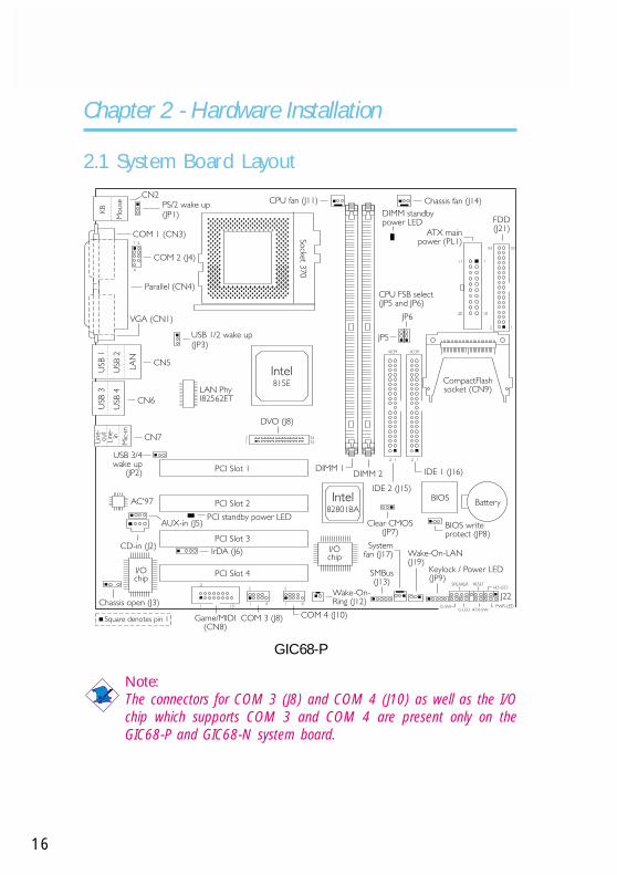
2.1 System Board Layout
Chapter 2 - Hardware Installation
Note:The connectors for COM 3 (J8) and COM 4 (J10) as well as the I/Ochip which supports COM 3 and COM 4 are present only on theGIC68-P and GIC68-N system board.
GIC68-P
21
9
2
1 9
2
1 15
2
1 9
HD-LEDSPEAKER RESET
J22
Socke
t370
CN2
KB
Mouse
COM 1 (CN3)
VGA (CN1)
Parallel (CN4)
LA
N
USB
1
USB
2
USB
3
USB
4Lin
e-
in
Lin
e-
out
Mic
-in
PS/2 wake up(JP1)
USB 1/2 wake up(JP3)
LAN PhyI82562ET
Intel815E
USB 3/4wake up
(JP2)
CN5
CN6
CN7
CPU fan (J11) Chassis fan (J14)
11
20
1
10
2 1
34 33
FDD(J21)
CPU FSB select(JP5 and JP6)
JP5
JP6
CompactFlashsocket (CN9)
IDE 1 (J16)
IDE 2 (J15)BIOS
Battery
Clear CMOS(JP7)
BIOS writeprotect (JP8)
Keylock / Power LED(JP9)
Wake-On-LAN(J19)
Systemfan (J17)
SMBus(J13)
Intel82801BA
I/Ochip
I/Ochip
Wake-On-Ring (J12)
COM 4 (J10)COM 3 (J8)Game/MIDI(CN8)
Chassis open (J3)
CD-in (J2)
AUX-in (J5)
AC'97
IrDA (J6)
DVO (J8)
12
3334
COM 2 (J4)
DIMM 1DIMM 2
PCI standby power LED
PCI Slot 1
PCI Slot 2
PCI Slot 3
PCI Slot 4
Square denotes pin 1
2 1
4039
2 1
4039
PWR-LEDATX-SWG-LED
G-SW
DIMM standbypower LED
ATX mainpower (PL1)

2Hardware Installation
17
GIC68-N

2
18
Hardware Installation
GIC68-B

2Hardware Installation
19
2.2 System Memory
Warning:Electrostatic discharge (ESD) can damage your system board,processor, disk drives, add-in boards, and other components. Performthe upgrade instruction procedures described at an ESD workstationonly. If such a station is not available, you can provide some ESDprotection by wearing an antistatic wrist strap and attaching it to ametal part of the system chassis. If a wrist strap is unavailable,establish and maintain contact with the system chassis throughoutany procedures requiring ESD protection.
.
.
.
.
.
.
.
.
The system board is equipped with two 168-pin DIMM (Dual In-lineMemory Module) sockets that support unbuffered PC-133/PC-100SDRAM DIMM for 133MHz/100MHz system memory bus. PCSDRAM (Synchronous Dynamic Random Access Memory) is a fastmemory interface technology that uses the clock on the chip tosynchronize with the CPU clock so that the timing of the memorychips and the timing of the CPU are synchronized. This saves timeduring transmission of data, subsequently increasing systemperformance.
The “System Memory Frequency” field in the Advanced ChipsetFeatures submenu of the BIOS must be set according to the type ofPC SDRAM DIMM used.
DIMM 1 DIMM 2

2
20
Hardware Installation
1. Pull the “tabs” which are at the ends of the socket to the side.
2. Position the DIMM above the socket with the “notches” in themodule aligned with the “keys” on the socket.
3. Seat the module vertically into the socket. Make sure it iscompletely seated. The tabs will hold the DIMM in place.
Pin 1
Notch
Key
TabTab
2.2.2 Installing the DIM Module
A DIM module simply snaps into a DIMM socket on the systemboard. Pin 1 of the DIM module must correspond with Pin 1 of thesocket.
The onboard VGA shares 1MB of the system memory. This is fixedregardless of the size of the system memory. Aside from the 1MBshared memory, it also uses Dynamic Video Memory Technology(DVMT). DVMT freely changes in size because graphics memory isallocated from the system memory according to current needs. Referto chapter 1 for the type of memory supported by the systemboard.

2Hardware Installation
21
2.3 Jumper Settings for Clearing CMOS Data
Clear CMOS(JP7)
123
2-3 On:Clear CMOS Data
1-2 On: Normal(default)
3 2 1 3 2 1
Clear CMOS Data - Jumper JP7
If you encounter the following,
a) CMOS data becomes corrupted.b) You forgot the supervisor or user password.c) You are unable to boot-up the computer system because the
processor’s clock/ratio was incorrectly set in the BIOS.
you can reconfigure the system with the default values stored in theROM BIOS.
To load the default values stored in the ROM BIOS, please followthe steps below.
1. Power-off the system.
2. Set JP7 pins 2 and 3 to On. Wait for a few seconds and set JP7back to its default setting, pins 1 and 2 On.
3. Now power-on the system.

2
22
Hardware Installation
If your reason for clearing the CMOS data is due to incorrectsetting of the processor’s clock/ratio in the BIOS, please proceedto step 4.
4. After powering-on the system, press <Del> to enter the mainmenu of the BIOS.
5. Select the Frequency/Voltage Control submenu and press<Enter>.
6. Set the “CPU Host/PCI Clock” or “CPU Clock Ratio” field to itsdefault setting or an appropriate bus clock or frequency ratio.Refer to the Frequency/Voltage Control section in chapter 3 formore information.
7. Press <Esc> to return to the main menu of the BIOS setuputility. Select “Save & Exit Setup” and press <Enter>.
8. Type <Y> and press <Enter>.

2Hardware Installation
23
2.4 Jumper Settings for Selecting the CPU’s FrontSide Bus
2-3 On1-2 On
CPU Front Side Bus Select - Jumpers JP5 and JP6
This jumper is used to select the front side bus of the CPU installedon the system board. The default setting is 1-2 On: Auto. The systemwill run according to the CPU’s FSB.
CPU FSB select(JP5 and JP6)
JP5
JP6
1
2
3
JP5 JP6
3
2
1
JP5 JP6
3
2
1
CPU
Auto*
66MHz
100MHz
133MHz
JP5
1-2 On
2-3 On
2-3 On
1-2 On
JP6
1-2 On
2-3 On
1-2 On
1-2 On
“*” denotes default setting

2
24
Hardware Installation
Important:Overclocking may result in the processor’s or system’s instabilityand is not guaranteed to provide better system performance. Ifyou are unable to boot your system due to overclocking, makesure to set these jumpers back to their default settings.

2Hardware Installation
25
PS/2 Wake Up Settings - Jumper JP1
The Wake-On-Keyboard/Wake-On-Mouse function allows you to usethe keyboard or PS/2 mouse to power-on the system. By default,JP1 is disabled. To use this function, set JP1 to 2-3 On. “Power OnFunction” in the Integrated Peripherals submenu of the BIOS mustbe set accordingly. Refer to chapter 3 for details.
Warning:1. If JP1 was enabled with a password set in the “KB Power
On Password” field, and now you wish to disable thekeyboard password function, make sure to set the “PowerOn Function” field to “Button Only” prior to setting JP1 todisabled. You will not be able to boot up the system if youfail to do so.
2.5 Jumper Settings for PS/2 Wake Up
PS/2 wake up(JP1)
1
2
3
2-3 On: 5VSB - Enabled1-2 On: VCC - Disabled(default)
1
2
3
1
2
3
.
.
.
.
.
.
.
.

2
26
Hardware Installation
2. The power button will not function once a keyboardpassword has been set in the “KB Power On Password”field of the Integrated Peripherals submenu. You must typethe correct password to power-on the system.
3. The 5VSB power source of your power supply mustsupport ≥720mA.

2Hardware Installation
27
2.6 Jumper Settings for USB Wake Up
USB Wake Up Settings - Jumpers JP2 and JP3
The Wake-On-USB Keyboard function allows you to use a USBkeyboard to wake up a system from the S3 (STR - Suspend ToRAM) state.
JP2 - for the USB keyboard that is connected to the USB 3 or USB4 port.
JP3 - for the USB keyboard that is connected to the USB 1 or USB2 port.
By default, this function is disabled. To use this function, set theappropriate jumper - pins 2 and 3 to On. “USB KB Wake-Up FromS3” in the Power Management Setup submenu of the BIOS mustalso be enabled.
USB 3/4wake up
(JP2)
USB 1/2wake up
(JP3)
1
2
3
1 2 3
1 2 31
2
3
JP3
JP2
1 2 31
2
3
JP3
JP2
2-3 On: 5VSB - Enabled1-2 On: VCC - Disabled(default)

2
28
Hardware Installation
Important:• If you are using the Wake-On-USB Keyboard function for 2
USB ports, the 5VSB power source of your power supplymust support ≥1.5A.
• If you are using the Wake-On-USB Keyboard function for 3or more USB ports, the 5VSB power source of your powersupply must support ≥2A.

2Hardware Installation
29
2.7 Jumper Settings for the Onboard LAN 2 Port(GIC68-N only)
1-2 On: Enabled(default)
2-3 On: Disabled
Onboard LAN 2 Settings - Jumper JP4
This jumper is used to enable or disable the onboard Intel 82559LAN chip that controls the LAN 2 port.
1 2 3 1 2 3

2
30
Hardware Installation
2.8 Jumper Settings for BIOS Write Protect
BIOS Write Protect Settings - Jumper JP8
The default setting is 2-3 On. This setting will protect the systemfrom unnecessary updating or flashing of the BIOS. It secures theBIOS therefore any updates to it will not take effect.
BIOS write protect(JP8)
1 2 3
1-2 On: BIOS WriteProtect Disabled
2-3 On: BIOS WriteProtect Enabled
(default)
1 2 3 1 2 3

2Hardware Installation
31
2.9 Rear Panel I/O Ports
PS/2Mouse
RJ45LAN 1Parallel
USB 1/2COM 1 VGA
Line-out
Line-in
Mic-in
PS/2 K/B
RJ45LAN 2
USB 3/4
PS/2Mouse
RJ45LANParallel
Line-out
Line-in
Mic-in
USB 1/2COM 1 VGA USB 3
GIC68-N
PS/2 K/B
GIC68-P and GIC68-B
USB 4

2
32
Hardware Installation
2.9.1 PS/2 Mouse and PS/2 Keyboard Ports
The system board is equipped with an onboard PS/2 mouse(Green) and PS/2 keyboard (Purple) ports - both at location CN2of the system board. The PS/2 mouse port uses IRQ12. If a mouseis not connected to this port, the system will reserve IRQ12 forother expansion cards.
The Wake-On-Keyboard/Mouse function allows you to use thekeyboard or PS/2 mouse to power-on the system.
To use this function:
• JP1 pins 2 and 3 must be set to On.
• “Power On Function” in the Integrated Peripherals submenu ofthe BIOS must be set accordingly. Refer to chapter 3 for moreinformation.
Warning:Make sure to turn off your computer prior to connecting ordisconnecting a mouse or keyboard. Failure to do so maydamage the system board.
PS/2 Mouse
PS/2 Keyboard
.
.
.
.
.
.
.
.
CN2
2Hardware Installation
33
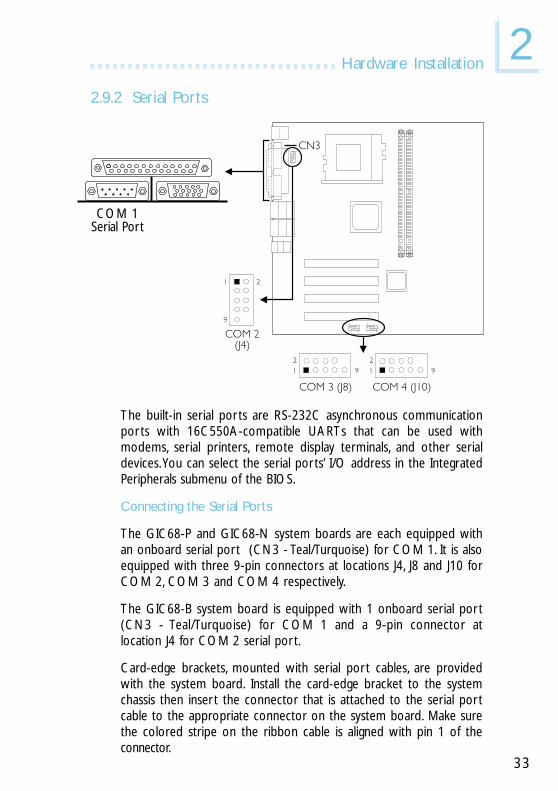
2.9.2 Serial Ports
The built-in serial ports are RS-232C asynchronous communicationports with 16C550A-compatible UARTs that can be used withmodems, serial printers, remote display terminals, and other serialdevices. You can select the serial ports’ I/O address in the IntegratedPeripherals submenu of the BIOS.
Connecting the Serial Ports
The GIC68-P and GIC68-N system boards are each equipped withan onboard serial port (CN3 - Teal/Turquoise) for COM 1. It is alsoequipped with three 9-pin connectors at locations J4, J8 and J10 forCOM 2, COM 3 and COM 4 respectively.
The GIC68-B system board is equipped with 1 onboard serial port(CN3 - Teal/Turquoise) for COM 1 and a 9-pin connector atlocation J4 for COM 2 serial port.
Card-edge brackets, mounted with serial port cables, are providedwith the system board. Install the card-edge bracket to the systemchassis then insert the connector that is attached to the serial portcable to the appropriate connector on the system board. Make surethe colored stripe on the ribbon cable is aligned with pin 1 of theconnector.
COM 1Serial Port
CN321
9
COM 2(J4)
21
92
1 9
2
1 9
COM 4 (J10)COM 3 (J8)
2
1 9
2
1 9

2
34
Hardware Installation
Parallel Port
2.9.3 Parallel Port
The system board has a standard parallel port (CN4 - Burgundy)for interfacing your PC to a parallel printer. It supports SPP, ECP andEPP modes. You can select the port’s mode in the Integrated Periph-erals submenu of the BIOS.
CN4
Setting
SPP(Standard Parallel Port)
ECP(Extended Capabilities Port)
EPP(Enhanced Parallel Port)
Function
Allows normal speed operation butin one direction only.
Allows parallel port to operate inbidirectional mode and at a speedfaster than the SPP’s data transferrate.
Allows bidirectional parallel port op-eration at maximum speed.

2Hardware Installation
35
2.9.4 VGA Port
The system board can only be used with an analog video monitor.Connect the monitor’s 15-pin D-shell cable connector to the VGAport (CN1 - Blue). If your monitor supports analog video but doesnot have a 15-pin D-shell connector, see your monitor dealer for theadapter or optional cable. After you plug the monitor cable into theVGA port, gently tighten the cable screws to hold the connector inplace. Some monitors have a switch that chooses between analogand TTL (or digital) operation. If your monitor has such a switch, setit for analog. You can configure the display in the Advanced ChipsetFeatures submenu of the BIOS.
VGA PortCN1

2
36
Hardware Installation
The system board is equipped with four onboard USB ports (CN5and CN6 - Black). USB allows data exchange between yourcomputer and a wide range of simultaneously accessible externalPlug and Play peripherals. You must have the proper drivers installedin your operating system to use the USB ports. Refer to youroperating system’s manual or documentation.
You can enable or disable the USB ports in the Integrated Peripher-als submenu (“USB Controller” field) of the BIOS.
The Wake-On-USB Keyboard function allows you to use a USBkeyboard to wake up a system from the S3 (STR - Suspend ToRAM) state.
To use this function:
• JP2 or JP3 pins 2 and 3 must be set to On.
• “USB KB Wake-Up From S3” in the Power Management Setupsubmenu of the BIOS must be set to Enabled.
2.9.5 Universal Serial Bus Ports
CN5
CN6
USB 2USB 1
USB 4USB 3

2Hardware Installation
37
2.9.6 RJ45 Fast-Ethernet Port
The GIC68-N system board is equipped with 2 onboard RJ45 fast-ethernet LAN ports at locations CN5 and CN6. GIC68-P andGIC68-B are each equipped with only 1 onboard LAN port atlocation CN5.
The LAN port allows the system board to connect to a local areanetwork by means of a network hub. The Intel 82559 chip on theGIC68-N system board which controls the LAN 2 port can beenabled or disabled using JP4. Refer to “Jumper Settings for theOnboard LAN 2 Port” in chapter 2 for more information.
CN5
CN6
RJ45 LAN 1
RJ45 LAN 2

2
38
Hardware Installation
Onboard Audio Jacks (CN7)
The system board is equipped with 3 audio jacks. A jack is a one-hole connecting interface for inserting a plug.
Line-out Jack (Lime)This jack is used to connect external speakers for audio output fromthe system board.
Line-in Jack (Light Blue)This jack can be connected to the line-out jack of any external audiodevices such as Hi-fi set, CD player, AM/FM radio tuner, synthesizer,etc. Connect a stereo cable from the line-out jack of your externaldevice to this line-in jack.
Mic-in Jack (Pink)Connect a microphone to the mic-in jack.
2.9.7 Audio Jacks
Line-out
Line-inMic-in

2Hardware Installation
39
2.10.1 Internal Audio Connectors
The CD-in and AUX-in connectors are used to receive audio from aCD-ROM drive, TV tuner or MPEG card.
Pin
1
2
3
4
Function
Left audio channel
Ground
Ground
Right audio channel
2.10 I/O Connectors

2
40
Hardware Installation
2
1 15
Game/MIDI(CN8)
151
2
The system board is equipped with a 15-pin connector at locationCN8 for connecting an external game/MIDI port. Connect yourgame/MIDI port cable to connector CN8. Make sure the coloredstripe on the ribbon cable is aligned with pin 1 of connector CN8.
The Game/MIDI port is identical to that of a standard PC gameadapter or game I/O port. This port works well with any applicationthat is compatible with the standard PC joystick. You can configurethe game port in the Integrated Peripherals submenu of the BIOS.
2.10.2 Game/MIDI Port

2Hardware Installation
41
2.10.3 Floppy Disk Drive Connector
The system board is equipped with a shrouded floppy disk driveconnector that supports two standard floppy disk drives. To preventimproper floppy cable installation, the shrouded floppy disk headerhas a keying mechanism. The 34-pin connector on the floppy cablecan be placed into the header only if pin 1 of the connector isaligned with pin 1 of the header. You can enable or disable thisfunction in the Integrated Peripherals submenu of the BIOS.
Connecting the Floppy Disk Drive Cable
1. Install the 34-pin header connector of the floppy disk drive cableinto the shrouded floppy disk header (J21) on the system board.The colored edge of the ribbon should be aligned with pin 1 ofJ21.
2. Install the other 34-pin header connector(s) into the disk drive(s).Align the colored edge of the daisy chained ribbon cable with pin1 of the drive edge connector(s). The end-most connector shouldbe attached to the drive you want to designate as Drive A.
2 1
34 33
FDD(J21)
12
3334

2
42
Hardware Installation
2.10.4 IDE Disk Drive Connector
The system board is equipped with two shrouded PCI IDE headersthat will interface four Enhanced IDE (Integrated Drive Electronics)disk drives. To prevent improper IDE cable installation, each shroudedPCI IDE header has a keying mechanism. The 40-pin connector onthe IDE cable can be placed into the header only if pin 1 of theconnector is aligned with pin 1 of the header. You can enable ordisable the onboard primary or secondary IDE controller in theIntegrated Peripherals submenu of the BIOS.
Connecting the IDE Disk Drive Cable
1. If you are connecting two IDE drives, install the 40-pin connectorof the IDE cable into the primary shrouded IDE header (IDE 1 -J16). If you are adding a third or fourth IDE device, install the40-pin connector of the other IDE cable into the secondaryshrouded IDE header (IDE 2 - J15).
2. Install the other 40-pin header connector(s) into the device withthe colored edge of the ribbon cable aligned with pin 1 of thedrive edge connector(s).
IDE 1(J16)
IDE 2(J15)
12
40 39
12
40 39
CompactFlashsocket (CN9)

2Hardware Installation
43
Note:Refer to your disk drive user’s manual for information aboutselecting proper drive switch settings.
Adding a Second IDE Disk Drive
When using two IDE drives, one must be set as the master and theother as the slave. Follow the instructions provided by the drivemanufacturer for setting the jumpers and/or switches on the drives.
The system board supports Enhanced IDE or ATA-2, ATA/33,ATA/66 or ATA/100 hard drives. We recommend that you use harddrives from the same manufacturer. In a few cases, drives from twodifferent manufacturers will not function properly when used together.The problem lies in the hard drives, not the system board.
Important:• CompactFlashTM and IDE 2 share the same channel. Since
CompactFlashTM on this board is always in Master mode, ifa CompactFlashTM card is installed in the socket, make surethe drive connected to the IDE 2 connector is set to Slavemode.
• If you encountered problems while using an ATAPI CD-ROMdrive that is set in Master mode, please set the CD-ROMdrive to Slave mode. Some ATAPI CD-ROMs may not berecognized and cannot be used if incorrectly set in Mastermode.

2
44
Hardware Installation
2.10.5 IrDA Connector
Pin
1
2
3
4
5
Function
VCC
N. C.
IRRX
Ground
IRTX
The system board is equipped with an IrDA connector for wirelessconnectivity between your computer and peripheral devices. TheIRDA (Infrared Data Association) specification supports datatransfers of 115K baud at a distance of 1 meter.
Connect your IrDA cable to connector J6 on the system board. Set“UART Mode Select” in the Integrated Peripherals submenu of theBIOS to the type of IrDA standard supported by your device. Youmust have the proper drivers installed in your operating system touse this connector. Refer to your operating system’s manual ordocumentation.
Note:The sequence of the pin functions on some IrDA cable may bereversed from the pin function defined on the system board.Make sure to connect the cable to the IrDA connectoraccording to their pin functions.
IrDA (J6)
1 2 3 4 5

2Hardware Installation
45
2.10.6 CPU Fan Connector
Pin
1
2
3
Function
Ground
Power
Sense
The CPU must be kept cool by using a fan with heatsink. Connectthe CPU fan to the 3-pin fan connector at location J11 on thesystem board. The system is capable of monitoring the speed of theCPU fan.
CPU fan(J11)
321

2
46
Hardware Installation
2.10.7 Chassis Fan Connector
Pin
1
2
3
If you are installing a chassis fan in the system unit, connect the fan’sconnector to location J14 on the system board. The fan will provideadequate airflow throughout the chassis to prevent overheating theCPU. The system is capable of monitoring and controlling the speedof the chassis fan. The chassis fan will automatically turn off once thesystem enters the Suspend mode.
Function
Ground
On/Off
Sense
321
Chassis fan(J14)

2Hardware Installation
47
2.10.8 System Fan Connector
If you are installing a system fan in the system unit, connect the fan’sconnector to location J17 on the system board. The system iscapable of monitoring and controlling the speed of the system fan.The system fan will automatically turn off once the system enters theSuspend mode.
System fan(J17)
3 2 1
Pin
1
2
3
Function
Ground
On/Off
Sense

2
48
Hardware Installation
Wake-On-LAN(J19)
3 2 1
2.10.9 Wake-On-LAN Connector
The Wake-On-LAN function is applicable only when you are using aLAN add-in card that has the same function. It will allow thenetwork to remotely power-on a Soft Power Down (Soft-Off) PC.However, if your system is in the Suspend mode, you can power-onthe system only through an IRQ or DMA interrupt.
To use the Wake-On-LAN function, you must enable the “Wake UpOn LAN_conn” field in the Power Management Setup of the BIOS.Your LAN card package should include a cable. Connect one end ofthe cable to the wakeup header on the card and the other end tolocation J19 on the system board. The network will detect MagicPacket and assert a wakeup signal to power-up the system. Refer tothe add-in card’s manual for details. Note: Your LAN card mustsupport the remote wake up function.
Important:The 5VSB power source of your power supply must support≥720mA.
Pin
1
2
3
Function
WOL
Ground
+5VSB

2Hardware Installation
49
2.10.10 Wake-On-Ring Connector
Wake-On-Ring(J12)
21
Pin
1
2
Function
Ground
RI#
The Wake-On-Ring connector is used to connect to an internalmodem card that has the same connector. It will allow the systemthat is in the Suspend mode or Soft Power Off mode to wake-up/power-on to respond to calls coming from the internal modem card.
To use this function, connect one end of the cable (that came withthe card) to the card’s wake-on-ring connector and the other end tolocation J12 on the system board. You must also enable “Power OnBy Ring_conn” in the Power Management Setup of the BIOS.
If you are using an external modem, the ring-on function will comethrough the serial port where the external modem is connected.
Important:If you are using a modem add-in card, the 5VSB power sourceof your power supply must support a minimum of ≥720mA.

2
50
Hardware Installation
2.10.11 SMBus Connector
SMBus (J13)
1 2 3 4 5
Pin
1
2
3
4
5
Function
3VSB
N. C.
SMBus Clk
SMBus Data
Ground
The SMBus (System Management Bus) connector is used to connectSMBus devices. It is a multiple device bus that allows multiple chipsto connect to the same bus allowing each device to initiate datatransfer.
2Hardware Installation
51
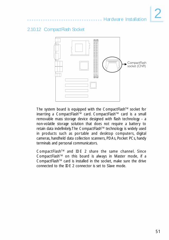
2.10.12 CompactFlash Socket
The system board is equipped with the CompactFlashTM socket forinserting a CompactFlashTM card. CompactFlashTM card is a smallremovable mass storage device designed with flash technology - anon-volatile storage solution that does not require a battery toretain data indefinitely. The CompactFlashTM technology is widely usedin products such as por table and desktop computers, digitalcameras, handheld data collection scanners, PDAs, Pocket PCs, handyterminals and personal communicators.
CompactFlashTM and IDE 2 share the same channel. SinceCompactFlashTM on this board is always in Master mode, if aCompactFlashTM card is installed in the socket, make sure the driveconnected to the IDE 2 connector is set to Slave mode.
CompactFlashsocket (CN9)

2
52
Hardware Installation
2.10.13 DVO Connector
DVO (J8)
12
3334
2 34
1 33
The Intel Digital Video Out (DVO) interface is a scaleable, low-voltage interface that ranges from 1.1V to 1.8V. It interfaces with adiscrete TV encoder to enable platform support for TV-Out, with adiscrete TMDS transmitter to enable platform support for DVI-compliant digital displays, or with an integrated TV encoder andTMDS transmitter. Refer to the next page for the pin function of theDVO interface.

2Hardware Installation
53
Pin
1
3
5
7
9
11
13
15
17
19
21
23
25
27
29
31
33
Function
PCIRST-
LTVDATA0
LTVDATA1
LTVDATA2
LTVDATA3
LTVDATA4
LTVDATA5
LTVDATA6
LTVDATA7
LTVDATA8
LTVDATA9
LTVDATA10
LTVDATA11
VCC3;O
VCC3;O
Ground
Ground
Pin
2
4
6
8
10
12
14
16
18
20
22
24
26
28
30
32
34
Function
GP22
CLKOUT0
CLKOUT1
TVVSYNC
TVRSYNC
TVLBLANK#
LTVCL
LTVDA
TVCLK1
VCC18
VCC18
VCC
VCC
+12V
+12V
Ground
Ground

2
54
Hardware Installation
2.10.14 Chassis Open Connector
Pin
1
2
3
4
Function
Ground
Chassis signal
N. C.
+5V
The “chassis open” function, when enabled, will alert you that thesystem chassis is open. To use this function, please follow the stepsbelow.
1. Connect the “chassis sensor” cable that is attached on yoursystem chassis to location J3 on the system board.
2. Install the “Winbond Hardware Doctor” utility contained in theprovided CD. By default, this function is disabled. When enabled,a warning message will appear when the chassis is open. Theutility can also be configured so that a beeping alarm will soundwhen the chassis is open. Refer to the “Winbond HardwareDoctor” section in chapter 4 for information on installing theutility.
Chassis open(J3)
1 2 3 4

2Hardware Installation
55
2.10.15 DIMM/PCI Standby Power LED
DIMM Standby Power LED
This LED will turn red when the system’s power is on or when it isin the Suspend state (Power On Suspend or Suspend to RAM). Itwill not light when the system is in the Soft-Off state.
PCI Standby Power LED
This LED will turn red when the system is in the power-on, Soft-Offor Suspend (Power On Suspend or Suspend to RAM) state.
Important:Lighted LEDs serve as a reminder that you must power-off thesystem then turn off the power supply’s switch or unplug thepower cord prior to installing any memory modules or add-incards.
DIMM standbypower LED
PCI standbypower LED

2
56
Hardware Installation
2.10.16 Power Connector
The pin function of the ATX power connector is shown below.
Pin
1
2
3
4
5
6
7
8
9
10
Function
3.3V
3.3V
Ground
+5V
Ground
+5V
Ground
PW-OK
5VSB
+12V
Pin
11
12
13
14
15
16
17
18
19
20
Function
3.3V
-12V
Ground
PS-ON
Ground
Ground
Ground
-5V
+5V
+5V
Important:The system board requires a minimum of 3.3V/6A electriccurrent.
11
20
1
10
ATX mainpower (PL1)
1
10
11
20
2Hardware Installation
57
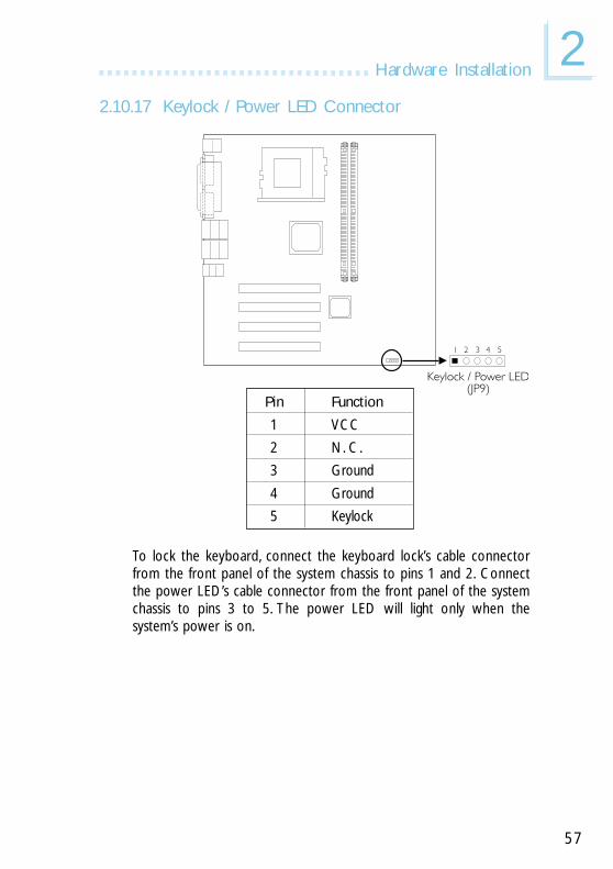
2.10.17 Keylock / Power LED Connector
Keylock / Power LED(JP9)
1 2 3 4 5
Pin
1
2
3
4
5
Function
VCC
N. C.
Ground
Ground
Keylock
To lock the keyboard, connect the keyboard lock’s cable connectorfrom the front panel of the system chassis to pins 1 and 2. Connectthe power LED’s cable connector from the front panel of the systemchassis to pins 3 to 5. The power LED will light only when thesystem’s power is on.

2
58
Hardware Installation
2.10.18 Front Panel Connector
HD-LED: Primary/Secondary IDE LEDThis LED will light when the hard drive is being accessed.
RESET: Reset SwitchThis switch allows you to reboot without having to power off thesystem thus prolonging the life of the power supply or system.
SPEAKER: Speaker ConnectorThis connects to the speaker installed in the system chassis.
G-SW: Green SwitchThis switch will allow your system to enter the Suspend mode.
G-LED: Green LEDThis LED will not light when the system’s power is on or when thesystem is in the S3 (STR - Suspend To RAM) state. It will blink everysecond when the system is in the S1 (POS - Power On Suspend)state.
ATX-SW: ATX Power SwitchDepending on the setting in the BIOS setup, this switch is a “dualfunction power button” that will allow your system to enter the Soft-Off or Suspend mode. Refer to “Soft-Off By PWR-BTTN” in thePower Management Setup submenu of the BIOS.
PWR-LED
G-SW
HD-LED
RESETSPEAKER
21
2019
ATX-SW
G-LEDFront panelconnector (J22)

2Hardware Installation
59
PWR-LED: Power/Standby LEDWhen the system’s power is on, this LED will light. When the systemis in the S1 (POS - Power On Suspend) state, it will blink everysecond. When the system is in the S3 (STR - Suspend To RAM)state, it will blink every 4 seconds.
Note:If a system did not boot-up and the Power/Standby LED didnot light after it was powered-on, it may indicate that the CPUor memory module was not installed properly. Please makesure they are properly inserted into their corresponding socket.
Pin
35
1416
810
1820
79
13151719
246
HD-LED(Primary/Secondary IDE LED)
G-LED(Green LED)
ATX-SW(ATX power switch)
G-SW(Green switch)
RESET(Reset switch)
SPEAKER(Speaker connector)
PWR-LED(Power/Standby LED)
Pin Assignment
HDD LED PowerHDD
Green LED PowerGround
PWRBT+PWRBT-
GroundSMI
GroundH/W Reset
Speaker DataN. C.GroundSpeaker Power
LED Power (+)LED Power (+)LED Power (-) or Standby Signal

60
3 Award BIOS Setup Utility
3.1 The Basic Input/Output System
The Basic Input/Output System (BIOS) is a program that takes careof the basic level of communication between the processor andperipherals. In addition, the BIOS also contains codes for variousadvanced features found in this system board. This chapter explainsthe Setup Utility for the Award BIOS.
After you power up the system, the BIOS message appears on thescreen and the memory count begins. After the memory test, thefollowing message will appear on the screen:
Press DEL to enter setup
If the message disappears before you respond, restart the system orpress the “Reset” button. You may also restart the system bypressing the <Ctrl> <Alt> and <Del> keys simultaneously.
When you press <Del>, the main menu screen will appear.
3.1.1 Standard CMOS Features
Use the arrow keys to highlight “Standard CMOS Features” andpress <Enter>. A screen similar to the one on the next page willappear.
Chapter 3 - Award BIOS Setup Utility
CMOS Setup Utility - Copyright (C) 1984-2000 Award Software
Standard CMOS Features
Advanced BIOS Features
Advanced Chipset Features
Integrated Peripherals
Power Management Setup
PnP/PCI Configurations
PC Health Status
Frequency/Voltage Control
Load Fail-Safe Defaults
Load Optimized Defaults
Set Supervisor Password
Set User Password
Save & Exit Setup
Exit Without Saving
EscF10
: Quit: Save & Exit Setup
↑↓→← : Select Item
Time, Date, Hard Disk Type...

61
3Award BIOS Setup Utility
Date
The date format is <day>, <month>, <date>, <year>. Day displaysa day, from Sunday to Saturday. Month displays the month, fromJanuary to December. Date displays the date, from 1 to 31. Yeardisplays the year, from 1994 to 2079.
Time
The time format is <hour>, <minute>, <second>. The time is basedon the 24-hour military-time clock. For example, 1 p.m. is 13:00:00.Hour displays hours from 00 to 23. Minute displays minutes from00 to 59. Second displays seconds from 00 to 59.
IDE Primary Master, IDE Primary Slave, IDE Secondary Master andIDE Secondary Slave
Move the cursor to the “IDE Primary Master”, “IDE Primary Slave”,“IDE Secondary Master” or “IDE Secondary Slave” field, then press<Enter>.
The settings on the screen are for reference only. Your version may not beidentical to this one.
↑↓→← Move
CMOS Setup Utility - Copyright (C) 1984-2000 Award SoftwareStandard CMOS Features
Date (mm:dd:yy)Time (hh:mm:ss)
IDE Primary MasterIDE Primary SlaveIDE Secondary MasterIDE Secondary Slave
Drive ADrive B
VideoHalt On
Base MemoryExtended MemoryTotal Memory
F6:Fail-Safe Defaults F7:Optimized DefaultsF1:General Help
Thu, Sep 5 20004 : 35 : 5
Press Enter NonePress Enter NonePress Enter NonePress Enter None
1.44M, 3.5 in.None
EGA/VGAAll, But Keyboard
640K129024K130048K
Item Help
Menu Level
Change the day, month,year and century
Enter:SelectF5:Previous Values
+/-/PU/PD:Value F10:Save ESC:Exit

62
3 Award BIOS Setup Utility
The settings on the screen are for reference only. Your version may not beidentical to this one.
↑↓→← :Move
Phoenix - AwardBIOS CMOS Setup UtilityIDE Primary Master
IDE HDD Auto Detection
IDE Primary MasterAccess Mode
Capacity
CylinderHeadPrecompLanding ZoneSector
F6:Fail-Safe Defaults F7:Optimized DefaultsF1:General Help
Press Enter
AutoAuto
0 M
0000
Item Help
Menu Level
Change the day, month,year and century
Enter:SelectF5:Previous Values
+/-/PU/PD:Value F10:Save ESC:Exit
IDE HDD Auto DetectionDetects the parameters of the drive. The parameters willautomatically be shown on the screen.
IDE Primary Master/Slave and IDE Secondary Master/SlaveIf you wish to define your own drive type manually, select “Manual”.The drive type information should be included in the documentationfrom your hard disk vendor. If you select ”Auto”, the BIOS will auto-detect the HDD & CD-ROM drive at the POST stage and showthe IDE for the HDD & CD-ROM drive. If a hard disk has notbeen installed, select “None”.
Access ModeFor hard drives larger than 528MB, you would typically select theLBA type. Certain operating systems require that you select Normalor Large. Please check your operating system’s manual or Help deskon which one to select.

63
3Award BIOS Setup Utility
CapacityDisplays the approximate capacity of the disk drive. Usually the sizeis slightly greater than the size of a formatted disk given by a diskchecking program.
CylinderThis field displays the number of cylinders.
HeadThis field displays the number of read/write heads.
PrecompThis field displays the number of cylinders at which to change thewrite timing.
Landing ZoneThis field displays the number of cylinders specified as the landingzone for the read/write heads.
SectorThis field displays the number sectors per track.
Drive A and Drive B
These fields identify the types of floppy disk drives installed.
None No floppy drive is installed360K, 5.25 in. 5-1/4 in. standard drive; 360KB capacity1.2M, 5.25 in. 5-1/4 in. AT-type high-density drive; 1.2MB capacity720K, 3.5 in. 3-1/2 in. double-sided drive; 720KB capacity1.44M, 3.5 in. 3-1/2 in. double-sided drive; 1.44MB capacity2.88M, 3.5 in. 3-1/2 in. double-sided drive; 2.88MB capacity

64
3 Award BIOS Setup Utility
Video
This field selects the type of video adapter used for the primarysystem monitor. Although secondary monitors are supported, you donot have to select the type. The default setting is EGA/VGA.
EGA/VGA Enhanced Graphics Adapter/Video Graphics Array. ForEGA, VGA, SVGA and PGA monitor adapters.
CGA 40 Color Graphics Adapter. Power up in 40-columnmode.
CGA 80 Color Graphics Adapter. Power up in 80-columnmode.
Mono Monochrome adapter. Includes high resolutionmonochrome adapters.
Halt On
This field determines whether the system will stop if an error isdetected during power up. The default setting is All Errors.
No Errors The system boot will not stop for any errors detected.All Errors The system boot will stop whenever the BIOS detects
a non-fatal error.All, But Keyboard The system boot will not stop for a keyboard
error; it will stop for all other errors.All, But Diskette The system boot will not stop for a disk error;
it will stop for all other errors.All, But Disk/Key The system boot will not stop for a disk or
keyboard error; it will stop for all other errors.
Base Memory
Displays the amount of base (or conventional) memory installed inthe system. The value of the base memory is typically 512K forsystems with 512K memory installed on the motherboard or 640Kfor systems with 640K or more memory installed on themotherboard.

65
3Award BIOS Setup Utility
Extended Memory
Displays the amount of extended memory detected during boot-up.
Total Memory
Displays the total memory available in the system.

66
3 Award BIOS Setup Utility
3.1.2 Advanced BIOS Features
The Advanced BIOS Features allows you to configure your systemfor basic operation. Some entries are defaults required by the systemboard, while others, if enabled, will improve the performance of yoursystem or let you set some features according to your preference.
Virus Warning
This field protects the boot sector and partition table of your hard diskdrive. When this field is enabled, the Award BIOS will monitor the bootsector and partition table of the hard disk drive. If an attempt is madeto write to the boot sector or partition table of the hard disk drive,the BIOS will halt the system and an error message will appear.
After seeing the error message, if necessary, you will be able to runan anti-virus program to locate and remove the problem before anydamage is done.
Many disk diagnostic programs which attempt to access the bootsector table will cause the warning message to appear. If you arerunning such a program, we recommend that you first disable this field.Also, disable this field if you are installing or running certain operating
CMOS Setup Utility - Copyright (C) 1984-2000 Award SoftwareAdvanced BIOS Features
Item Help
Menu Level
Allows you to choosethe VIRUS warningfeature for IDE HardDisk boot sectorprotection. If thisfunction is enabled andsomeone attempt towrite data into thisarea, BIOS will show awarning message onscreen and alarm beep
↑↓→← MoveF6:Fail-Safe Defaults F7:Optimized Defaults
F1:General HelpEnter:SelectF5:Previous Values
+/-/PU/PD:Value F10:Save ESC:Exit
Virus WarningCPU Internal CacheExternal CacheCPU L2 Cache ECC CheckingProcessor Serial NumberQuick Power On Self TestFirst Boot DeviceSecond Boot DeviceThird Boot DeviceFourth Boot DeviceSwap Floppy DriveBoot Up Floppy SeekBoot Up NumLock StatusGate A20 OptionSecurity OptionAPIC ModeMPS Version Control For OSOS Select For DRAM > 64MBHDD S.M.A.R.T. CapabilityReport No FDD for WIN 95Small Logo (EPA) Show
DisabledEnabledEnabledEnabledEnabledEnabledFloppyHDD-0LS/ZIPEnabledDisabledDisabledOnFastSetupEnabled1.4Non-OS2DisabledYesDisabled
The screen above list all the fields available in the Advanced BIOS Featuressubmenu, for ease of reference in this manual. In the actual CMOS setup,you have to use the scroll bar to view the fields. The settings on the screenare for reference only. Your version may not be identical to this one.

67
3Award BIOS Setup Utility
systems like Windows® 98SE/2000/ME/XP or the operating systemmay not install nor work.
CPU Internal Cache and External Cache
These fields speed up the memory access. The default is Enabled,which provides better performance by enabling cache.
CPU L2 Cache ECC Checking
The processors supported by the system board come with built-inLevel 2 cache. By default, ECC is enabled to check the Level 2 cache.If you are not using this function, set this field to Disabled.
Processor Serial Number
This field will appear only when you are using Intel’s Pentium III orlater processor. These processors come with an individual"processor serial number" which by default is activated. Therefore,when connected to the Internet, the processor transmits the serialnumber online making it possible to track your online activity. Thisfield provides you the option of disabling this function.
Quick Power On Self Test
This field speeds up Power On Self Test (POST) whenever thesystem is powered on. The BIOS will shorten or skip some checkitems during POST. To attain the shortest POST time, select “Fast”.
First Boot Device, Second Boot Device, Third Boot Device andFourth Boot Device
Select the drive to boot first, second, third and fourth in the “FirstBoot Device” “Second Boot Device”, “Third Boot Device” and“Fourth Boot Device” fields respectively. The BIOS will boot theoperating system according to the sequence of the drive selected.

68
3 Award BIOS Setup Utility
Swap Floppy Drive
When this field is enabled and the system is booting from the floppydrive, the system will boot from drive B instead of drive A. Whenthis field is disabled and the system is booting from the floppy drive,the system will boot from drive A. You must have two floppy drivesto use this function.
Boot Up Floppy Seek
When enabled, the BIOS will check whether the floppy disk driveinstalled is 40 or 80 tracks. Note that the BIOS cannot distinguishbetween 720K, 1.2M, 1.44M and 2.88M drive types as they are all 80tracks. When disabled, the BIOS will not search for the type of floppydisk drive by track number. Note that there will not be any warningmessage if the drive installed is 360KB.
Boot Up NumLock Status
This allows you to determine the default state of the numerickeypad. By default, the system boots up with NumLock on whereinthe function of the numeric keypad is the number keys. When set toOff, the function of the numeric keypad is the arrow keys.
Gate A20 Option
This entry allows you to select how gate A20 is handled. Gate A20is a device used to address memory above 1 Mbyte. Initially, gate A20was handled via the keyboard controller. Today, while keyboards stillprovide this support, it is more common, and much faster, for thesystem chipset to provide support for gate A20.

69
3Award BIOS Setup Utility
Security Option
This field determines when the system will prompt for the password- everytime the system boots or only when you enter the BIOSsetup. Set the password in the Set Supervisor/User Passwordsubmenu.
System The system will not boot and access to Setup will bedenied unless the correct password is entered at theprompt.
Setup The system will boot, but access to Setup will be deniedunless the correct password is entered at the prompt.
APIC Mode
Leave this field in its default setting.
MPS Version Control for OS
This field is used to select the MPS version that the system board isusing.
OS Select for DRAM > 64MB
This field allows you to access the memory that is over 64MB inOS/2.
HDD S.M.A.R.T. Capability
The system board supports SMART (Self-Monitoring, Analysis andReporting Technology) hard drives. SMART is a reliability predictiontechnology for ATA/IDE and SCSI drives. The drive will providesufficient notice to the system or user to backup data prior to thedrive’s failure. The default is Disabled. If you are using hard drivesthat suppor t S.M.A.R.T., set this field to Enabled. SMART issupported in ATA/33 or later hard drives.

70
3 Award BIOS Setup Utility
Report No FDD For WIN 95
The options are Yes and No.
Small Logo(EPA) Show
Enabled The EPA logo will appear during system boot-up.Disabled The EPA logo will not appear during system boot-up.

71
3Award BIOS Setup Utility
3.1.3 Advanced Chipset Features
This section gives you functions to configure the system based onthe specific features of the chipset. The chipset manages bus speedsand access to system memory resources. These items should notbe altered unless necessary. The default settings have been chosenbecause they provide the best operating conditions for your system.The only time you might consider making any changes would be ifyou discovered some incompatibility or that data was being lostwhile using your system.
SDRAM CAS Latency Time
The default setting is 3 which is 3 clock cycles for the CAS latency.
SDRAM Cycle Time Tras/Trc
This field selects the number of SCLKs for an access cycle.
CMOS Setup Utility - Copyright (C) 1984-2000 Award SoftwareAdvanced Chipset Features
Item Help
Menu Level
↑↓→← MoveF6:Fail-Safe Defaults F7:Optimized Defaults
F1:General HelpEnter:SelectF5:Previous Values
+/-/PU/PD:Value F10:Save ESC:Exit
SDRAM CAS Latency TimeSDRAM Cycle Time Tras/TrcSDRAM RAS-to-CAS DelaySDRAM RAS Precharge TimeSystem BIOS CacheableVideo BIOS CacheableCPU Latency TimerDelayed TransactionAGP Graphics Aperture SizeDisplay Cache FrequencySystem Memory FrequencyOn-Chip Video Window Size
GFX ScalingShow VBIOS MessageTV FormatOutput Device SyncronousOutput Device Priority
* Onboard Display Cache Setting *CAS# LatencyPaging Mode ControlRAS-to-CAS OverrideRAS# TimingRAS# Precharge Timing
3AutoAutoAutoDisabledDisabledEnabledEnabled64100 MHzAuto64MBAuto/EDIDDisabledNTSCDisabledCRT/FP/TV
3Openby CAS# LTFastFast
The screen above list all the fields available in the Advanced ChipsetFeatures submenu, for ease of reference in this manual. In the actual CMOSsetup, you have to use the scroll bar to view the fields. The settings on thescreen are for reference only. Your version may not be identical to this one.

72
3 Award BIOS Setup Utility
SDRAM RAS-to-CAS Delay
This field allows you to insert a timing delay between the CAS andRAS strobe signals, used when DRAM is written to, read from, orrefreshed. This field applies only when synchronous DRAM is installedin the system.
SDRAM RAS Precharge Time
If there is insufficient number of cycles for the RAS to accumulate itscharge before DRAM refresh, the refresh may be incomplete and theDRAM may fail to retain data.
System BIOS Cacheable
When this field is enabled, accesses to the system BIOS ROMaddressed at F0000H-FFFFFH are cached, provided that the cachecontroller is enabled. The larger the range of the Cache RAM, thehigher the efficiency of the system.
Video BIOS Cacheable
As with caching the system BIOS, enabling the Video BIOS cache willallow access to video BIOS addresssed at C0000H to C7FFFH tobe cached, if the cache controller is also enabled. The larger the rangeof the Cache RAM, the faster the video performance.
CPU Latency Timer
The options are Enabled and Disabled.
Delayed Transaction
When enabled, this function frees up the PCI bus for other PCImasters during the PCI-to-ISA transactions. This allows PCI and ISAbuses to be used more efficiently and prevents degradation ofperformance on the PCI bus when ISA accesses are made.
AGP Graphics Aperture Size
This field is relevant to the memory-mapped graphics data of theAGP card installed in your system. Leave this in its default setting.

73
3Award BIOS Setup Utility
Display Cache Frequency
This field is used to select the display cache frequency.
System Memory Frequency
Auto The BIOS will automatically detect the type of PCSDRAM DIMM installed on the system board.
100 MHz Select this option if you are using a PC-100 SDRAMDIMM.
133 MHz Select this option if you are using a PC-133 SDRAMDIMM.
On-Chip Video Window Size
This field selects the on-chip video window size.
For DVO interface only - the following fields will appear onlywhen you are using the DVO interface.
GFX Scaling
This default setting is Auto/EDID.
Show VBIOS Message
This default setting is Disabled.
TV Format
This default setting is NTSC.
Output Device Syncronous
This default setting is Disabled.
Output Device Priority
This default setting is CRT/FP/TV.

74
3 Award BIOS Setup Utility
Onboard Display Cache Setting
CAS# LatencyThis field is used to select the local memory clock periods. Theoptions are 2 and 3.
Paging Mode ControlThis field is used to select the paging mode control. The optionsare Open and Close.
RAS-to-CAS OverrideThis field is used to select the display cache clock periods control.The options are “by CAS# LT” and “Override(2)”.
RAS# TimingThis field controls RAS# active to Protegra, and refresh to RAS#active delay (in local memory clocks). The options are Slow andFast.
RAS# Precharge TimingThis field controls RAS# precharge (in local memory clocks). Theoptions are Slow and Fast.

75
3Award BIOS Setup Utility
3.1.4 Integrated Peripherals
The screen above list all the fields available in the Integrated Peripheralssubmenu, for ease of reference in this manual. In the actual CMOS setup,you have to use the scroll bar to view the fields. The settings on the screenare for reference only. Your version may not be identical to this one.
XX
CMOS Setup Utility - Copyright (C) 1984-2000 Award SoftwareIntegrated Peripherals
Item Help
Menu Level
↑↓→← MoveF6:Fail-Safe Defaults F7:Optimized Defaults
F1:General HelpEnter:SelectF5:Previous Values
+/-/PU/PD:Value F10:Save ESC:Exit
On-Chip Primary PCI IDEOn-Chip Secondary PCI IDEIDE Primary Master PIOIDE Primary Slave PIOIDE Secondary Master PIOIDE Secondary Slave PIOIDE Primary Master UDMAIDE Primary Slave UDMAIDE Secondary Master UDMAIDE Secondary Slave UDMAUSB ControllerUSB Keyboard SupportInit Display FirstAC97 AudioWatchdog FunctionIDE HDD Block ModePower On FunctionKB Power On PasswordHot Key Power OnOnboard FDC ControllerOnboard Serial Port 1Onboard Serial Port 2UART Mode SelectRxD, TxD ActiveIR Transmission DelayUR2 Duplex ModeUse IR PinsOnboard Parallel PortParallel Port ModeEPP Mode SelectECP Mode Use DMAPWR Lost Resume StateGame Port AddressMidi Port AddressMidi Port IRQOnboard Serial Port 3Serial Port 3 Use IRQOnboard Serial Port 4Serial Port 4 Use IRQ
EnabledEnabledAutoAutoAutoAutoAutoAutoAutoAutoEnabledDisabledPCI SlotAutoDisabledEnabledDisabledEnterCtrl-F1Enabled3F8/IRQ42F8/IRQ3NormalHi,LoEnabledHalfRxD2TxD2378/IRQ7ECP+EPPEPP1.71LASTATEDisabledDisabled103E8IRQ112E8IRQ10
X
XXXX
On-Chip Primary PCI IDE and On-Chip Secondary PCI IDE
These fields allow you to enable or disable the primary andsecondary IDE controller. The default is Enabled. Select Disabled ifyou want to add a different hard drive controller.
IDE Primary Master/Slave PIO and IDE Secondary Master/SlavePIO
PIO means Programmed Input/Output. Rather than have the BIOSissue a series of commands to effect a transfer to or from the diskdrive, PIO allows the BIOS to tell the controller what it wants andthen let the controller and the CPU perform the complete task bythemselves. Your system supports five modes, 0 (default) to 4, which

76
3 Award BIOS Setup Utility
primarily differ in timing. When Auto is selected, the BIOS will selectthe best available mode after checking your drive.
Auto The BIOS will automatically set the system according toyour hard disk drive’s timing.
Mode 0-4 You can select a mode that matches your hard diskdrive’s timing. Caution: Do not use the wrong settingor you will have drive errors.
IDE Primary Master/Slave UDMA and IDE Secondary Master/Slave UDMA
These fields allow you to set the Ultra DMA in use. When Auto isselected, the BIOS will select the best available option after checkingyour hard drive or CD-ROM.
Auto The BIOS will automatically detect the settings for you.Disabled The BIOS will not detect these categories.
USB Controller
We recommend that you leave this field in its default setting -Enabled.
USB Keyboard Support
By default, USB Keyboard Support is Disabled. However, if you areusing a USB keyboard under DOS, make sure to enable thisfunction.
Init Display First
This field is used to select whether to initialize the onboard VGA orPCI first when the system boots.
Onboard When the system boots, it will first initialize theonboard VGA.
PCI Slot When the system boots, it will first initialize PCI.
AC97 Audio
Auto Select this option when using the onboard audio codec,primary or secondary audio riser card, or audio/modemriser card.
Disabled Select this option when using a PCI sound card.

77
3Award BIOS Setup Utility
Watchdog Function
Enabled Enables the Watchdog function.Disabled Disables the Watchdog function.
Refer to Appendix A for more information.
IDE HDD Block Mode
Enabled The IDE HDD uses the block mode. The system BIOSwill check the hard disk drive for the maximum blocksize the system can transfer. The block size will dependon the type of hard disk drive.
Disabled The IDE HDD uses the standard mode.
Power On Function
This field allows you to use the keyboard or PS/2 mouse to power-on the system. To use this function, make sure JP1 is set to 2-3 On -Enabled. Refer to “Jumper Settings for PS/2 Wake Up” in chapter 2for more information.
Button only Default setting. Uses the power button to poweron the system.
Warning:If JP1 was previously enabled with a pass-word set in the “KB Power On Password” field,and now you wish to disable the keyboardpassword function, make sure to set this fieldto disabled prior to setting JP1 to disabled(1-2 On). You will not be able to boot up thesystem if you fail to do so.
Password When this option is selected, move the cursor tothe “KB Power On Password” field and press<Enter>. Enter your password. You can enter up to5 characters. Type in exactly the same password toconfirm, then press <Enter>.
Important:The power button will not function once akeyboard password has been set in the “KBPower On Password” field. You must type thecorrect password to power-on the system. Ifyou forgot the password, power-off the
.
.
.
.
.
.
.
.

78
3 Award BIOS Setup Utility
system and remove the battery. Wait for afew seconds and install it back beforepowering-on the system.
Hot Key When this option is selected, move the cursor tothe “Hot Key Power On” field to select a functionkey you would like to use to power-on the system.The options are from Ctrl-F1 to Ctrl-F12.
Mouse Left When this option is selected, double-click the leftbutton of the mouse to power-on the system.
Mouse Right When this option is selected, double-click the rightbutton of the mouse to power-on the system.
Any Key Press any key to power-on the system.Keyboard 98 When this option is selected, press the “wake up”
key of the Windows 98 compatible keyboard topower-on the system.
Onboard FDC Controller
Enabled Enables the onboard floppy disk controller.Disabled Disables the onboard floppy disk controller.
Onboard Serial Port 1 and Onboard Serial Port 2
Auto The system will automatically select an I/O address forthe onboard serial port 1 and serial port 2.
3F8/IRQ4, 2F8/IRQ3, 3E8/IRQ4, 2E8/IRQ3 Allows you tomanually select an I/O address for the onboard serialport 1 and serial port 2.
Disabled Disables the onboard serial port 1 and/or serial port 2.
UART Mode Select
The system board supports IrDA function for wireless connectivitybetween your computer and peripheral devices. You may not useIrDA (J6) and the COM 2 serial port (J4) at the same time. If youare using the COM 2 serial port, make sure this field is set toNormal.
To use the IrDA function, follow the steps below.
1. Connect your IrDA cable to connector J6 on the systemboard.

79
3Award BIOS Setup Utility
2. Set the “UART Mode Select” field to the type of IrDAstandard supported by your IrDA peripheral/device (IrDA orASKIR). For better transmission of data, your IrDA peripheraldevice must be within a 30o angle and within a distance of 1meter.
3. Set the “RxD, TxD Active”, “IR Transmission Delay”, “UR2 DuplexMode” and “Use IR Pins” fields appropriately.
RxD, TxD Active
The options are Hi, Lo; Lo, Hi; Lo, Lo; and Hi, Hi.
IR Transmission Delay
If this field is Enabled, transmission of data will be slower. This isrecommended when you encounter transmission problem with yourdevice. The options are: Enabled and Disabled.
UR2 Duplex Mode
Half Data is completely transmitted before receiving data.Full Transmits and receives data simultaneously.
Use IR Pins
The options are IR-Rx2Tx2 and RxD2TxD2.
Onboard Parallel Port
378/IRQ7, 3BC/IRQ7, 278/IRQ5 Selects the I/O address andIRQ for the onboard parallel port.
Disabled Disables the onboard parallel port.
Parallel Port Mode
The options are SPP, EPP, ECP and ECP+EPP. These apply to astandard specification and will depend on the type and speed ofyour device. Refer to your peripheral’s manual for the best option.
SPPAllows normal speed operation but in one direction only.
“ECP (Extended Capabilities Port)”Allows parallel port to operate in bidirectional mode and at aspeed faster than the normal mode’s data transfer rate.

80
3 Award BIOS Setup Utility
“EPP (Enhanced Parallel Port)”Allows bidirectional parallel port operation at maximum speed.
If you selected EPP, the “EPP Mode Select” field is selectable. If youselected ECP, the “ECP Mode Use DMA” field is selectable. If youselected ECP+EPP, both “EPP Mode Select” and “ECP Mode UseDMA” are selectable.
EPP Mode Select
This field is used to select the EPP mode of the parallel port.
ECP Mode Use DMA
This is used to select a DMA channel of the parallel port.
PWR Lost Resume State
Keep Off When power returns after an AC power failure, thesystem’s power is off. You must press the Powerbutton to power-on the system.
Keep On When power returns after an AC power failure, thesystem will automatically power-on.
LASTATE When power returns after an AC power failure, thesystem will return to the state where you left offbefore power failure occurs. If the system’s power isoff when AC power failure occurs, it will remain offwhen power returns. If the system’s power is onwhen AC power failure occurs, the system will power-on when power returns.
Game Port Address
This field is used to select the game port’s address.
Midi Port Address
This field is used to select the midi port’s address. If you haveselected the midi port’s address, you may select its IRQ in the “MidiPort IRQ” field.
Midi Port IRQ
This field is used to select the midi port’s IRQ.

81
3Award BIOS Setup Utility
Onboard Serial Port 3 (GIC68-P and GIC68-N only)
This field is used to select the serial port 3’s I/O address.
Serial Port 3 Use IRQ (GIC68-P and GIC68-N only)
This field is used to select the serial port 3’s IRQ address. This fieldis not configurable if the “Onboard Serial Port 3” field is set toDisabled.
Onboard Serial Port 4 (GIC68-P and GIC68-N only)
This field is used to select the serial port 4’s I/O address.
Serial Port 4 Use IRQ (GIC68-P and GIC68-N only)
This field is used to select the serial port 4’s IRQ address. This fieldis not configurable if the “Onboard Serial Port 4” field is set toDisabled.

82
3 Award BIOS Setup Utility
3.1.5 Power Management Setup
The Power Management Setup allows you to configure your systemto most effectively save energy.
ACPI Function
This function should be enabled only in operating systems that sup-port ACPI. Currently, only Windows®®®®® 98/2000/ME/XP supports thisfunction. If you want to use the Suspend to RAM function, make surethis field is enabled then select “S3(STR)” in the “ACPI Suspend Type”field.
ACPI Suspend Type
This field is used to select the type of Suspend mode.
S1(POS) Enables the Power On Suspend function.S3(STR) Enables the Suspend to RAM function. Refer to “Using
the Suspend to RAM Function” in appendix A formore information.
X
XX
CMOS Setup Utility - Copyright (C) 1984-2000 Award SoftwarePower Management Setup
Item Help
Menu Level
↑↓→← MoveF6:Fail-Safe Defaults F7:Optimized Defaults
F1:General HelpEnter:SelectF5:Previous Values
+/-/PU/PD:Value F10:Save ESC:Exit
X
ACPI FunctionACPI Suspend TypeRun VGABIOS if S3 ResumePower ManagementVideo Off MethodVideo Off In SuspendSuspend TypeModem Use IRQSuspend ModeHDD Power DownSoft-Off By PWR-BTTNWake-Up by PCI / PME#Power On by Ring_connWake Up On LAN_connUSB KB Wake-Up From S3CPU Thermal-ThrottlingResume by Alarm
Date(of Month) AlarmTime (hh:mm:ss) Alarm
** Reload Global Timer Events **
Primary IDE0Primary IDE1Secondary IDE0Secondary IDE1FDD, COM, LPT PortPCI PIRQ[A-D]#
EnabledS1(POS)AutoUser DefineDPMSYesPwrOn SuspendNADisabledDisabledInstant-OffDisabledDisabledDisabledDisabled50.0%Disabled00 : 0 : 0
DisabledDisabledDisabledDisabledDisabledDisabled
The screen above list all the fields available in the Power Management Setupsubmenu, for ease of reference in this manual. In the actual CMOS setup,you have to use the scroll bar to view the fields. The settings on the screenare for reference only. Your version may not be identical to this one.

83
3Award BIOS Setup Utility
Run VGABIOS if S3 Resume
When this field is set to Auto, the system will initialize the VGA BIOSwhen it wakes up from the S3 state.
Power Management
This field allows you to select the type (or degree) of power savingby changing the length of idle time that elapses before the Suspendmode and HDD Power Down fields are activated.
Min Saving Minimum power saving time for the Suspend Modeand HDD Power Down = 1 hr.
Max Saving Maximum power saving time for the. SuspendMode and HDD Power Down = 1 min.
User Define Allows you to set the power saving time in the“Suspend Mode” and “HDD Power Down” fields.
Video Off Method
This determines the manner in which the monitor is blanked.
V/H SYNC + Blank This selection will cause the system to turnoff the vertical and horizontal synchronizationports and write blanks to the video buffer.
Blank Screen This option only writes blanks to the video buffer.DPMS Initializes display power management signaling. Use
this option if your video board supports it.
Video Off In Suspend
This field is used to activate the video off feature when the systementers the Suspend mode. The options are Yes and No.
Suspend Type
This field is used to select the type of Suspend Mode.

84
3 Award BIOS Setup Utility
Modem Use IRQ
This field is used to set an IRQ channel for the modem installed inyour system.
Suspend Mode
This is selectable only when the Power Management field is set toUser Define. When the system enters the Suspend mode accordingto the power saving time selected, the CPU and onboardperipherals will be shut off.
HDD Power Down
This is selectable only when the Power Management field is set toUser Define. When the system enters the HDD Power Down modeaccording to the power saving time selected, the hard disk drive willbe powered down while all other devices remain active.
Soft-Off by PWR-BTTN
This field allows you to select the method of powering off yoursystem.
Hold 4 Sec. Regardless of whether the Power Managementfunction is enabled or disabled, if the power buttonis pushed and released in less than 4 sec, thesystem enters the Suspend mode. The purpose ofthis function is to prevent the system from poweringoff in case you accidentally “hit” or pushed thepower button. Push and release again in less than 4sec to restore. Pushing the power button for morethan 4 seconds will power off the system.
Instant-Off Pressing and then releasing the power button atonce will immediately power off your system.
Wake-Up by PCI / PME#
Enabled Access to a PCI card such as a modem or onboardLAN will cause the system to wake up. The PCI cardmust support the wake up function.
Disabled The system will not wake up despite access to the PCIcard or onboard LAN.

85
3Award BIOS Setup Utility
Power On By Ring_conn
Set this field to Enabled to use the modem ring-on function. This willallow your system to power-on to respond to calls coming from anexternal or internal modem. Refer to “Wake-On-Ring Connector” inchapter 2 for more information.
Wake Up On LAN_conn
If you are using a LAN card that supports the remote wake upfunction, set this field to Enabled. The will allow the network toremotely wake up a Soft Power Down (Soft-Off) PC. However, ifyour system is in the Suspend mode, you can wake up the systemonly through an IRQ or DMA interrupt. Refer to “Wake-On-LANConnector” in chapter 2 for more information.
USB KB Wake-Up From S3
Set this field to Enabled to use the Wake-On-USB Keyboardfunction. This function allows you to use a USB keyboard to wake upa system from the S3 (STR - Suspend To RAM) state. Refer to“Jumper Settings for USB Wake Up” in chapter 2 for moreinformation.
CPU Thermal-Throttling
We recommend that you leave this field in its default setting.
Resume By Alarm
Enabled When Enabled, you can set the date and time youwould like the Soft Power Down (Soft-Off) PC topower-on in the “Date (of Month) Alarm” and “Time(hh:mm:ss) Alarm” fields. However, if the system is beingaccessed by incoming calls or the network (Resume OnRing/LAN) prior to the date and time set in thesefields, the system will give priority to the incoming callsor network.
Disabled Disables the automatic power-on function. (default)

86
3 Award BIOS Setup Utility
Date (of Month) Alarm
0 The system will power-on everyday according to thetime set in the “Time (hh:mm:ss) Alarm” field.
1-31 Select a date you would like the system to power-on.The system will power-on on the set date, and time setin the “Time (hh:mm:ss) Alarm” field.
Time (hh:mm:ss) Alarm
This is used to set the time you would like the system to power-on.If you want the system to power-on everyday as set in the “Date(of Month) Alarm” field, the time set in this field must be later thanthe time of the RTC set in the Standard CMOS Features submenu.
Reload Global Timer Events
When enabled, access to the specified field (Primary IDE 0/1,Secondary IDE 0/1, FDD/COM/LPT Port or PCI PIRQ[A-D]#) willcause the system to wake up completely from the powermanagement mode. When disabled, the system will not wake upfrom the power management mode despite access to the specifiedfield.

87
3Award BIOS Setup Utility
3.1.6 PnP/PCI Configurations
This section describes configuring the PCI bus system. It coverssome very technical items and it is strongly recommended that onlyexperienced users should make any changes to the default settings.
PNP OS Installed
The options are Yes and No.
Reset Configuration Data
Enabled The BIOS will reset the Extended System ConfigurationData (ESCD) once automatically. It will then recreate anew set of configuration data.
Disabled The BIOS will not reset the configuration data.
Resources Controlled By
The Award Plug and Play BIOS has the capability to automaticallyconfigure all of the boot and Plug and Play compatible devices.
Auto The system will automatically detect the settings for you.Manual Choose the specific IRQ in the “IRQ Resources” field.
The settings on the screen are for reference only. Your version may not beidentical to this one.
X
CMOS Setup Utility - Copyright (C) 1984-2000 Award SoftwarePnP/PCI Configurations
PNP OS InstalledReset Configuration Data
Resources Controlled ByIRQ Resources
PCI/VGA Palette SnoopINT Pin 1 AssignmentINT Pin 2 AssignmentINT Pin 3 AssignmentINT Pin 4 AssignmentINT Pin 5 AssignmentINT Pin 6 AssignmentINT Pin 7 AssignmentINT Pin 8 Assignment
YesDisabled
Auto(ESCD)Press Enter
DisabledAutoAutoAutoAutoAutoAutoAutoAuto
Item Help
Menu Level
Default is Disabled.Select Enabled toreset Extended SystemConfiguration Data(ESCD) when you exitSetup if you haveinstalled a new add-onand the systemreconfiguration hascaused such a seriousconflict that the OScannot boot.
↑↓→← MoveF6:Fail-Safe Defaults F7:Optimized Defaults
F1:General HelpEnter:SelectF5:Previous Values
+/-/PU/PD:Value F10:Save ESC:Exit

88
3 Award BIOS Setup Utility
IRQ Resources
This field is used to set each system interrupt to either Legacy ISAor PCI.
PCI For devices compliant with the PCI bus architecture.Legacy ISA For devices compliant with the original PC AT bus
specification.
PCI/VGA Palette Snoop
This field determines whether the MPEG ISA/VESA VGA cards canwork with PCI/VGA or not. The default value is Disabled.
Enabled MPEG ISA/VESA VGA cards work with PCI/VGA.Disabled MPEG ISA/VESA VGA cards does not work with PCI/
VGA.
INT Pin 1 Assignment to INT Pin 8 Assignment
By default, an IRQ is automatically assigned to each field. You mayalso manually assign an IRQ to these fields.

89
3Award BIOS Setup Utility
3.1.7 PC Health Status
CPU Warning Temperature
This field is used to select the CPU’s temperature limit. Once the systemhas detected that the CPU’s temperature exceeded the limit set in thisfield, a warning alarm will beep.
Current System Temperature, Current CPU Temperature, CurrentSystem Fan Speed, Current CPU Fan Speed and Current ChassisFan Speed
These fields show the internal temperature of the system, currenttemperature of the CPU, and the current fan speed of the system,CPU and chassis fans in RPM (Revolutions Per Minute).
CPU Core, CPU VTT and VCC3
These fields show the voltage of the processor.
The settings on the screen are for reference only. Your version may not beidentical to this one.
CMOS Setup Utility - Copyright (C) 1984-2000 Award SoftwarePC Health Status
CPU Warning TemperatureCurrent System Temp.Current CPU TemperatureCurrent System Fan SpeedCurrent CPU Fan SpeedCurrent Chassis Fan SpeedCPU CoreCPU VTTVCC3+5 V :+12 V :-12 V :VBAT (V) :5VSB (V) :
Disabled27C/80F37C/98F
0 RPM0 RPM0 RPM
Item Help
Menu Level
↑↓→← MoveF6:Fail-Safe Defaults F7:Optimized Defaults
F1:General HelpEnter:SelectF5:Previous Values
+/-/PU/PD:Value F10:Save ESC:Exit
1.45 V1.18 V1.75 V5.05 V
12.03 V-11.37 V
3.21 V5.40 V

90
3 Award BIOS Setup Utility
+5V, +12V, -12V, VBAT (V) and 5VSB (V)
These fields show the output voltage of the power supply.
If you want a warning message to pop-up or a warning alarm tosound when an abnormal condition occurs, you must install theWinbond Hardware Doctor utility. This utility is included in the CDthat came with the system board. Refer to the “Winbond HardwareDoctor” section in chapter 4 for more information.

91
3Award BIOS Setup Utility
3.1.8 Frequency/Voltage Control
The settings on the screen are for reference only. Your version may not beidentical to this one.
CMOS Setup Utility - Copyright (C) 1984-2000 Award SoftwareFrequency/Voltage Control
Auto Detect DIMM/PCI ClkSpread SpectrumCPU Host/PCI ClockCPU Clock Ratio
EnabledEnabledDisabledX 3
Item Help
Menu Level
↑↓→← MoveF6:Fail-Safe Defaults F7:Optimized Defaults
F1:General HelpEnter:SelectF5:Previous Values
+/-/PU/PD:Value F10:Save ESC:Exit
Auto Detect DIMM/PCI Clk
When enabled, the system will automatically send clock signals toexisting DIMM or PCI devices.
Spread Spectrum
Leave this field in its default setting. Do not alter this setting unlessadvised by an engineer or technician.
CPU Host/PCI Clock
This field provides several options for selecting the external systembus clock of the processor. The PCI clock will at the same timeappear next to the external bus clock selected. For example, if youselected “66/33”, 66MHz is the external bus clock and 33MHz is thePCI clock. Regardless of the type of processor used, the defaultsetting is “Default”. Under this setting, the system will run accordingto the processor’s clock frequency.
Important:Overclocking may result to the processor’s or system’sinstability and are not guaranteed to provide better systemperformance.

92
3 Award BIOS Setup Utility
CPU Clock Ratio
This field is used to select the CPU’s frequency ratio.
Important:• The frequency ratio of some processors may have been
locked by the manufacturer. If you are using this kind ofprocessor, setting an extended ratio for the processor willhave no effect. The system will instead use its factorydefault ratio.
• The frequency ratio of processors greater than 8x has beenlocked by the manufacturer and will no longer have theflexibility of using extended ratios. Therefore, the system willuse the processor’s factory default ratio.
If you selected an option other than the default setting and is unableto boot up the system, clear the CMOS data by setting JP7 to 2-3On. All fields in the BIOS Setup will automatically be set to theirdefault settings.

93
3Award BIOS Setup Utility
3.1.9 Load Fail-Safe Defaults
The “Load Fail-Safe Defaults” option loads the troubleshootingdefault values permanently stored in the ROM chips. These settingsare not optimal and turn off all high performance features. Youshould use these values only if you have hardware problems.Highlight this option in the main menu and press <Enter>. Themessage below will appear.
Load Fail-Safe Defaults (Y/N)? N
If you want to proceed, type <Y> and press <Enter>. The defaultsettings will be loaded.
3.1.10 Load Optimized Defaults
The “Load Optimized Defaults” option loads optimized settings fromthe BIOS ROM. Use the default values as standard values for yoursystem. Highlight this option in the main menu and press <Enter>.The message below will appear.
Load Optimized Defaults (Y/N)? N
Type <Y> and press <Enter> to load the Setup default values.

94
3 Award BIOS Setup Utility
3.1.11 Set Supervisor Password
If you want to protect your system and setup from unauthorizedentry, set a supervisor’s password with the “System” option selectedin the Advanced BIOS Features. If you want to protect access tosetup only, but not your system, set a supervisor’s password with the“Setup” option selected in the Advanced BIOS Features. You will notbe prompted for a password when you cold boot the system.
Use the arrow keys to highlight “Set Supervisor Password” andpress <Enter>. The message below will appear.
Enter Password:
Type in the password. You are limited to eight characters. Whendone, the message below will appear:
Confirm Password:
You are asked to verify the password. Type in exactly the samepassword. If you type in a wrong password, you will be promptedto enter the correct password again. To delete or disable thepassword function, highlight “Set Supervisor Password” and press<Enter>, instead of typing in a new password. Press the <Esc> keyto return to the main menu.
3.1.12 Set User Password
If you want another user to have access only to your system butnot to setup, set a user’s password with the “System” optionselected in the Advanced BIOS Features. If you want a user to entera password when trying to access setup, set a user’s password withthe “Setup” option selected in the Advanced BIOS Features.
Using user’s password to enter Setup allows a user to access only“Set User Password” that appears in the main menu screen. Accessto all other options is denied. To set, confirm, verify, disable or deletea user’s password, follow the procedures described in the section“Set Supervisor Password”.

95
3Award BIOS Setup Utility
3.1.13 Save & Exit Setup
When all the changes have been made, highlight “Save & Exit Setup”and press <Enter>. The message below will appear:
Save to CMOS and Exit (Y/N)? N
Type “Y” and press <Enter>. The modifications you have made willbe written into the CMOS memory, and the system will reboot. Youwill once again see the initial diagnostics on the screen. If you wish tomake additional changes to the setup, press <Ctrl> <Alt> <Esc>simultaneously or <Del> after memory testing is done.
3.1.14 Exit Without Saving
When you do not want to save the changes you have made,highlight “Exit Without Saving” and press <Enter>. The messagebelow will appear:
Quit Without Saving (Y/N)? N
Type “Y” and press <Enter>. The system will reboot and you willonce again see the initial diagnostics on the screen. If you wish tomake any changes to the setup, press <Ctrl> <Alt> <Esc>simultaneously or <Del> after memory testing is done.

96
3 Award BIOS Setup Utility
3.2 Updating the BIOS
To update the BIOS, you will need the new BIOS file and a flashutility, AWDFLASH.EXE. Please contact technical support or yoursales representative for the files.
1. Save the new BIOS fi le along with the flash uti l ityAWDFLASH.EXE to a floppy disk.
2. Reboot the system and enter the Award BIOS Setup Utility toset the first boot drive to “Floppy”.
3. Save the setting and reboot the system.
4. After the system booted from the floppy disk, execute the flashutility by typing AWDFLASH.EXE. The following screen will appear.
5. Type the new BIOS file name onto the gray area that is next to“File Name to Program” then press <Enter>.
Award BIOS Flash Utility V.8.15B(C) Phoenix Technologies Ltd. All Rights Reserved.
(The current BIOS information will appear in this area.)
File Name to Program :

97
3Award BIOS Setup Utility
6. The following will appear.
Do You Want to Save BIOS (Y/N)
This question refers to the current existing BIOS in your system.We recommend that you save the current BIOS and its flashutility; just in case you need to reinstall the BIOS. To save thecurrent BIOS, press <Y> then enter the file name of the currentBIOS. Otherwise, press <N>.
7. The following will then appear.
Press “Y” to Program or “N” to Exit
8. Press <Y> to flash the new BIOS.

98
4 Supported Software
4.1 Desktop Management Interface (DMI)
The system board comes with a DMI built into the BIOS. DMI, alongwith the appropriately networked software, is designed to makeinventory, maintenance and troubleshooting of computer systems easier.With DMI, a network administrator or MIS engineer can remotelyaccess some information about a particular computer system withoutphysically going to it. Quite often a service call may be unnecessary asthe problem can be solved remotely.
The DMI utility in the BIOS automatically records various informationabout your system configuration. Information about the type and speedof CPU, type and amount of memory for each memory slot, BIOSrevision level, types of add-in PCI boards and components, certainrevision numbers of hardware installed, etc. are automatically detectedand stored in the DMI pool, which is a part of the system board'sPlug and Play BIOS. Additional information, such as ISA basedperipherals, which may not be automatically detected, can be manuallyrecorded in the DMI pool by using the Add DMI menu. The DMI pooldata is then verified or updated whenever the system hardware orsetup is altered.
4.1.1 Running the DMI Utility
To run the DMI utility, type: DMICFG.EXE. Please contact technicalsupport or your sales representative for the utility.
The DMI utility must run in real mode with at least 180K of basememory. Memory managers like HIMEM.SYS (required by Windows)must not be installed. You may do this by using one of the 3 methodslisted below.
1. Boot up from a system diskette without the AUTOEXEC.BAT andCONFIG.SYS files,
2. “REM” HIMEM.SYS in the CONFIG.SYS, or
3. Press <F5> during bootup to bypass your AUTOEXEC.BAT andCONFIG.SYS files.
Chapter 4 - Supported Software

99
4Supported Software
4.1.2 Using the DMI Utility
The four menus located on top of the DMI Configuration Utility screenare Edit DMI, Add DMI, Load DMI File and Save DMI File. Use the← or → (left or right) arrow keys to select a menu from the Menubar.
On the left side of the screen is a list of the system configuration items.Use the ↑ or ↓ (up or down) arrow keys to select an item.
The commands at the bottom of the screen will allow you to navigatethrough the various setup menus.
Edit DMI
1. Use the ← or → arrow keys to select the Edit DMI menu.
2. Highlight the item on the left screen that you would like to editby using the ↑ or ↓ arrow keys, then press <Enter>.
3. The cursor will move to the screen you select allowing you to editinformation. The screen will also display the auto-detectedinformation.
4. Press <F10> to update the edited information into the flash ROM.
Move cursor ENTER-Accept DEL-Delete ESC-Abort&Exit↑ ↓ ↑ ↓ ↑ ↓ ↑ ↓ ↑ ↓ ←←←←←→→→→→
Award DMI Configuration Utility Copyright Award Software Inc, 1996[Edit DMI] [Add DMI] [Load DMI File] [Save DMI File]
BIOSSystem
Enclosure/ChassisProcessor
Memory ControllerMemory ModuleMemory ModuleMemory ModuleMemory Module
CacheCache
Port ConnectorPort ConnectorPort ConnectorPort ConnectorPort ConnectorPort ConnectorPort ConnectorSystem Slots
*** BIOS Auto Detect ***
Type : BIOS InformationHandle : 0000
Vendor Name :BIOS Version :BIOS Starting Address Segment : E000BIOS Build Date :BIOS Characteristics :Size of BIOS ROM : 0256K

100
4 Supported Software
Add DMI
1. Use the ← or → arrow keys to select the Add DMI menu.
2. Highlight the item on the left screen that you would like to addby using the ↑ or ↓ arrow keys, then press <Enter>.
3. The cursor will move to the screen you select allowing you to enterinformation about the added item.
4. Press <F10> to save information into the flash ROM.
To view information about the added items, go to the Edit DMI menu.
Load DMI File
1. Use the ← or → arrow keys to select the Load DMI File menu.
2. The following message will appear.
Press [Enter] to select DMI file for load
Press <Enter>.
3. The DMI files will appear on the screen. Select the file you wouldlike to load and press <Enter>.
4. The following message will appear.
Do you want to execute? (Y/N)
Type <Y>. All previous DMI structures will be destroyed and thenew file will be saved into the flash ROM.
Save DMI File
1. Use the ← or → arrow keys to select the Save DMI File menu.
2. The following message will appear.
Press [Enter] to select DMI file for save
Press <Enter>.
3. Enter the directory and filename under which you would like theDMI file saved.

101
4Supported Software
4.2 Drivers, Utilities and Software Applications
The CD that came with the system board contains drivers, utilitiesand software applications required to enhance the performance ofthe system board.
Insert the CD into a CD-ROM drive. The autorun screen (MainBoard Utility CD) will appear. If after inserting the CD, "Autorun" didnot automatically start (which is, the Main Board Utility CD screendid not appear), please go directly to the root directory of the CDand double-click "Setup".

102
4 Supported Software
4.2.1 Intel 815 INF Update Utility
The Intel 815 INF Update Utility is used for updating Windows
98/ME/2000/XP's INF files so that the Intel chipset can berecognized and configured properly in the system.
To install the utility, please follow the steps below.
1. Click “Intel 815 INF Update Utility for Windows 98/ME/2000/XP”. The following screen will appear.
2. Follow the prompts on the screen to complete installation.
3. Reboot the system for the utility to take effect.

103
4Supported Software
4.2.2 Intel 815 Graphics Drivers
To install the driver, please follow the steps below.
1. Click “Intel 815 Graphics Drivers”. The following screen willappear.
2. Follow the prompts on the screen to complete installation.
3. Reboot the system for the driver to take effect.

104
4 Supported Software
4.2.3 Realtek Audio Drivers
The audio drivers are supported in the following operating systems:Windows 98 SE, Windows ME, Windows NT 4.0, Windows
2000 and Windows XP.
To install the driver, please follow the steps below.
1. Click “Realtek Audio Drivers”. The following screen will appear.
2. Follow the prompts on the screen to complete installation.
3. Reboot the system for the driver to take effect.

105
4Supported Software
4.2.4 Intel 562/599 LAN Drivers
To install the driver, please follow the steps below.
1. Click “Intel 562/599 LAN Drivers”. The following screen willappear.
2. Follow the prompts on the screen to complete installation.
3. Reboot the system for the driver to take effect.

106
4 Supported Software
4.2.5 Winbond Hardware Doctor
The Winbond Hardware Doctor is capable of monitoring thesystem’s hardware conditions such as the temperature of the CPUand system, voltage, and speed of the CPU, chassis and system fans.It also allows you to manually set a range to the items beingmonitored. If the values are over or under the set range, a warningmessage will pop-up. The utility can also be configured so that abeeping alarm will sound whenever an error occurs. We recommendthat you use the “Default Setting” which is the ideal setting thatwould keep the system in good working condition.
Note:Use this utility only in Windows®®®®® 98, Windows®®®®® 98 SE,Windows®®®®® ME, Windows®®®®® 2000, Windows NT®®®®® 4.0 orWindows®®®®® XP operating system.
To install Hardware Monitor, please follow the steps below.
1. Click “Winbond Hardware Doctor”. The screen below will appear.
2. Follow the prompts on the screen to complete installation.
3. Restart the system.

107
4Supported Software
4.2.6 Microsoft DirectX 8.1
To install, please follow the steps below.
1. Click “Microsoft DirectX 8.1”. The following screen will appear.
2. Click “Yes” to continue.
3. Follow the prompts on the screen to complete installation.
4. Reboot the system for the driver to take effect.

108
4 Supported Software
4.3 Installation Notes
1. "Autorun" ONLY supports the Windows 98 SE, Windows ME,Windows 2000, Windows NT 4.0 and Windows XPoperating systems. If after inserting the CD, "Autorun" did notautomatically start (which is, the Main Board Utility CD screendid not appear), please go directly to the root directory of theCD and double-click "Setup".
2. All steps or procedures to install software drivers are subject tochange without notice as the softwares are occassionally updated.Please contact technical support or your sales representative forthe latest version of the drivers or software applications.

109
AWatchdog Timer
Appendix A - Watchdog Timer
A.1 Watchdog Timer
The following are parameters for setting the time interval of theWatchdog Timer function. The system will be regularly “cleared”according to the set time interval. If the system hangs or fails tofunction, it will also reset according to the time interval so that yoursystem will continue to operate.
Debug <Enter>
- o 370,87 <Enter>
- o 370,87 <Enter>
- o 370,07 <Enter>
- o 371,08 <Enter>
- o 370,f2 <Enter>
- o 371,XY <Enter>
“XY” is the Watchdog Time count value for the “00h to “FFh” rangewherein the time can be set from 0 sec. to 255 sec.
To use the Watchdog function, you must also set the “WatchdogFunction” field in the Integrated Peripherals submenu of the AwardBIOS utility to Enabled.

B
110
Using the Suspend to RAM Function
B.1 Using the Suspend to RAM Function
If you are using the Windows®®®®® 98 operating system, please followthe steps below.
1. Select “Power Management Setup” in the main menu screen andpress <Enter>.
2. In the “ACPI Function” field, select “Enabled”.
3. In the “ACPI Suspend Type” field, select “S3(STR)”.
Appendix B - Using the Suspend to RAM Function
4. Press <Esc> to return to the main menu.
5. Select “Save & Exit Setup” and press <Enter>. Type <Y> andpress <Enter>.
X
XX
CMOS Setup Utility - Copyright (C) 1984-2000 Award SoftwarePower Management Setup
Item Help
Menu Level
↑↓→← MoveF6:Fail-Safe Defaults F7:Optimized Defaults
F1:General HelpEnter:SelectF5:Previous Values
+/-/PU/PD:Value F10:Save ESC:Exit
X
ACPI FunctionACPI Suspend TypeRun VGABIOS if S3 ResumePower ManagementVideo Off MethodVideo Off In SuspendSuspend TypeModem Use IRQSuspend ModeHDD Power DownSoft-Off By PWR-BTTNWake-Up On PCI/LAN1,2Power On by RingWake Up On LANUSB KB Wake-Up From S3CPU Thermal-ThrottlingResume by Alarm
Date(of Month) AlarmTime (hh:mm:ss) Alarm
** Reload Global Timer Events **
Primary IDE0Primary IDE1Secondary IDE0Secondary IDE1FDD, COM, LPT PortPCI PIRQ[A-D]#
EnabledS1(POS)AutoUser DefineDPMSYesPwrOn SuspendNADisabledDisabledInstant-OffDisabledDisabledDisabledDisabled50.0%Disabled00 : 0 : 0
DisabledDisabledDisabledDisabledDisabledDisabled
The screen above list all the fields available in the Power Management Setupsubmenu, for ease of reference in this manual. In the actual CMOS setup,you have to use the scroll bar to view the fields. The settings on the screenare for reference only. Your version may not be identical to this one.

BUsing the Suspend to RAM Function
111
6. Install Windows®®®®® 98 by typing the following parameter. This isto ensure that the ACPI function is supported.
[drive]:>setup /p j
If you have previously installed Windows®®®®® 98, you need toupgrade the system in order to support ACPI. Please contactMicrosoft for upgrade information.
7. Boot Windows®®®®® 98. In the Windows®®®®® 98 desktop, click theStart button. Move the cursor to Settings, then click ControlPanel.
To check whether ACPI was properly installed, double-click theSystem icon. In the System Properties dialog box, click the“Device Manager” tab. In “View devices by type”, click “Systemdevices”.

B
112
Using the Suspend to RAM Function
9. Click File System. In the “Typical role of this computer” field,select “Mobile or docking system”. Click Apply, then click OK.Restart the computer.
8. Double-click the System icon. In the System Properties dialogbox, click the Performance tab.

BUsing the Suspend to RAM Function
113
10. Repeat step 7 to open the Control Panel dialog box. Double-click the Power Management icon.
11. Click the Advanced tab. In the “When I press the powerbutton on my computer” field, select “Standby”.

B
114
Using the Suspend to RAM Function
12. After completing the steps above and you want to power-offthe computer, you do not need to go through the process ofclosing files, applications and operating system. You can power-off the computer at once by pressing the power button orselecting “Standby” when you shut down Windows®®®®® 98.
To power-on the computer, just press the power button. Theoperating session where you left off when you power-off thecomputer will resume in not more than 8 seconds. However,the power button will not function if a keyboard password hasbeen set in the “KB Power On Password” field of theIntegrated Peripherals submenu. You must type the password topower-on the computer.
If you have changed the color or resolution (in the DisplayProperties dialog box), do not apply the settings withoutrestarting. You must restart the computer.
Important:If you are unable to use the Suspend to RAM function (afterperforming the steps above in Windows®®®®® 98 or when you arein-Windows®®®®® 2000/ME), please check whether your add-incards or devices support this function. If this function is notsupported, you need to download the appropriate driver fromtheir respective website.

CSystem Error Message
115
When the BIOS encounters an error that requires the user tocorrect something, either a beep code will sound or a message willbe displayed in a box in the middle of the screen and the message,PRESS F1 TO CONTINUE, CTRL-ALT-ESC or DEL TO ENTERSETUP, will be shown in the information box at the bottom. EnterSetup to correct the error.
C.1 POST Beep
There are two kinds of beep codes in the BIOS. One code indicatesthat a video error has occured and the BIOS cannot initialize thevideo screen to display any additional information. This beep codeconsists of a single long beep followed by three short beeps. Theother code indicates that a DRAM error has occured. This beepcode consists of a single long beep.
C.2 Error Messages
One or more of the following messages may be displayed if theBIOS detects an error during the POST. This list indicates the errormessages for all Awards BIOSes:
CMOS BATTERY HAS FAILEDThe CMOS battery is no longer functional. It should be replaced.
Caution:Danger of explosion if battery incorrectly replaced. Replace onlywith the same or equivalent type recommended by themanufacturer. Dispose of used batteries according to thebattery manufacturer’s instructions.
CMOS CHECKSUM ERRORChecksum of CMOS is incorrect. This can indicate that CMOS hasbecome corrupt. This error may have been caused by a weakbattery. Check the battery and replace if necessary.
DISPLAY SWITCH IS SET INCORRECTLYThe display switch on the motherboard can be set to eithermonochrome or color. This indicates the switch is set to a different
Appendix C - System Error Message

C
116
System Error Message
setting than indicated in Setup. Determine which setting is correct,either turn off the system and change the jumper or enter Setup andchange the VIDEO selection.
FLOPPY DISK(S) fail (80)Unable to reset floppy subsystem.
FLOPPY DISK(S) fail (40)Floppy type mismatch.
Hard Disk(s) fail (80)HDD reset failed.
Hard Disk(s) fail (40)HDD controller diagnostics failed.
Hard Disk(s) fail (20)HDD initialization error.
Hard Disk(s) fail (10)Unable to recalibrate fixed disk.
Hard Disk(s) fail (08)Sector Verify failed.
Keyboard is locked out - Unlock the keyThe BIOS detects that the keyboard is locked. Keyboard controller ispulled low.
Keyboard error or no keyboard presentCannot initialize the keyboard. Make sure the keyboard is attachedcorrectly and no keys are being pressed during the boot.
Manufacturing POST loopSystem will repeat POST procedure infinitely while the keyboardcontroller is pull low. This is also used for the M/B burn in test at thefactory.
BIOS ROM checksum error - System haltedThe checksum of ROM address F0000H-FFFFFH is bad.
Memory test failThe BIOS reports memory test fail if the memory has error(s).

DTroubleshooting
117
D.1 Troubleshooting Checklist
This chapter of the manual is designed to help you with problemsthat you may encounter with your personal computer. To efficientlytroubleshoot your system, treat each problem individually. This is toensure an accurate diagnosis of the problem in case a problem hasmultiple causes.
Some of the most common things to check when you encounterproblems while using your system are listed below.
1. The power switch of each peripheral device is turned on.2. All cables and power cords are tightly connected.3. The electrical outlet to which your peripheral devices are
connected is working. Test the outlet by plugging in a lamp orother electrical device.
4. The monitor is turned on.5. The display’s brightness and contrast controls are adjusted
properly.6. All add-in boards in the expansion slots are seated securely.7. Any add-in board you have installed is designed for your system
and is set up correctly.
Monitor/Display
If the display screen remains dark after the system is turned on:
1. Make sure that the monitor’s power switch is on.2. Check that one end of the monitor’s power cord is properly
attached to the monitor and the other end is plugged into aworking AC outlet. If necessary, try another outlet.
3. Check that the video input cable is properly attached to themonitor and the system’s display adapter.
4. Adjust the brightness of the display by turning the monitor’sbrightness control knob.
Appendix D - Troubleshooting

D
118
Troubleshooting
The picture seems to be constantly moving.
1. The monitor has lost its vertical sync. Adjust the monitor’s verticalsync.
2. Move away any objects, such as another monitor or fan, thatmay be creating a magnetic field around the display.
3. Make sure your video card’s output frequencies are supportedby this monitor.
The screen seems to be constantly wavering.
1. If the monitor is close to another monitor, the adjacent monitormay need to be turned off. Fluorescent lights adjacent to themonitor may also cause screen wavering.
Power Supply
When the computer is turned on, nothing happens.
1. Check that one end of the AC power cord is plugged into a liveoutlet and the other end properly plugged into the back of thesystem.
2. Make sure that the voltage selection switch on the back panel isset for the correct type of voltage you are using.
3. The power cord may have a “short” or “open”. Inspect the cordand install a new one if necessary.
Floppy Drive
The computer cannot access the floppy drive.
1. The floppy diskette may not be formatted. Format the disketteand try again.
2. The diskette may be write-protected. Use a diskette that is notwrite-protected.
3. You may be writing to the wrong drive. Check the pathstatement to make sure you are writing to the targeted drive.
4. There is not enough space left on the diskette. Use anotherdiskette with adequate storage space.

DTroubleshooting
119
Hard Drive
Hard disk failure.
1. Make sure the correct drive type for the hard disk drive hasbeen entered in the BIOS.
2. If the system is configured with two hard drives, make sure thebootable (first) hard drive is configured as Master and thesecond hard drive is configured as Slave. The master hard drivemust have an active/bootable partition.
Excessively long formatting period.
1. If your hard drive takes an excessively long period of time toformat, it is likely a cable connection problem. However, if yourhard drive has a large capacity, it will take a longer time toformat.
Parallel Port
The parallel printer doesn’t respond when you try to print.
1. Make sure that your printer is turned on and that the printer ison-line.
2. Make sure your software is configured for the right type ofprinter attached.
3. Verify that the onboard LPT port’s I/O address and IRQ settingsare configured correctly.
4. Verify that the attached device works by attaching it to a parallelport that is working and configured correctly. If it works, theprinter can be assumed to be in good condition. If the printerremains inoperative, replace the printer cable and try again.

D
120
Troubleshooting
Serial Port
The serial device (modem, printer) doesn’t output anything or isoutputting garbled characters.
1. Make sure that the serial device’s power is turned on and thatthe device is on-line.
2. Verify that the device is plugged into the correct serial port onthe rear of the computer.
3. Verify that the attached serial device works by attaching it to aserial port that is working and configured correctly. If the serialdevice does not work, either the cable or the serial device has aproblem. If the serial device works, the problem may be due tothe onboard I/O or the address setting.
4. Make sure the COM settings and I/O address are configuredcorrectly.
Keyboard
Nothing happens when a key on the keyboard was pressed.
1. Make sure the keyboard is properly connected.2. Make sure there are no objects resting on the keyboard and
that no keys are pressed during the booting process.
System Board
1. Make sure the add-in card is seated securely in the expansionslot. If the add-in card is loose, power off the system, re-installthe card and power up the system.
2. Check the jumper settings to ensure that the jumpers areproperly set.
3. Verify that all memory modules are seated securely into thememory sockets.
4. Make sure the memory modules are in the correct locations.5. If the board fails to function, place the board on a flat surface
and seat all socketed components. Gently press each componentinto the socket.
6. If you made changes to the BIOS settings, re-enter setup andload the BIOS defaults.


