
≈ 30 Lectures , 5 Assignments
Recommended Texts:
Surveying : H Kahmen & W Faig
+ many other texts
APG3017D
SURVEYING III
Theodolite errors and mitigation
Centring
Electronic circle reading systems
Vertical circle indexing compensation
Vertical axis tilt sensors
General observing principles with electronic angle measurements
Module 3: Theodolite Measurement
and Errors2
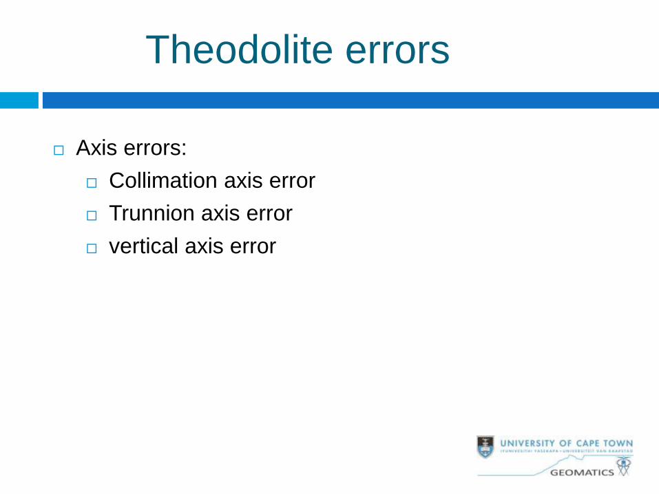
Theodolite errors
Axis errors:
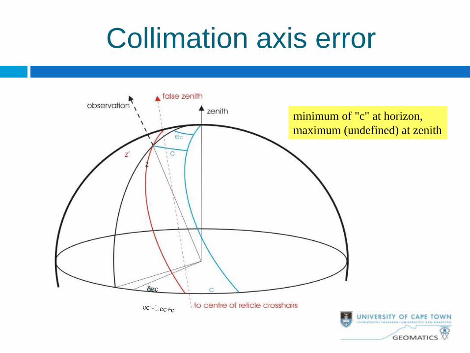
Collimation axis error
Trunnion axis error
vertical axis error
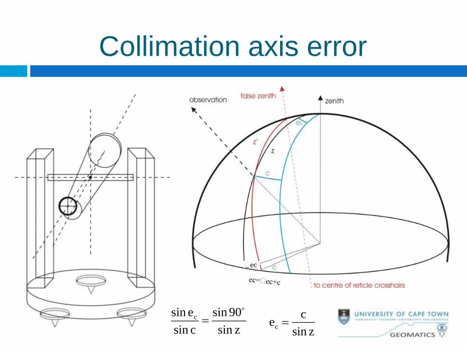
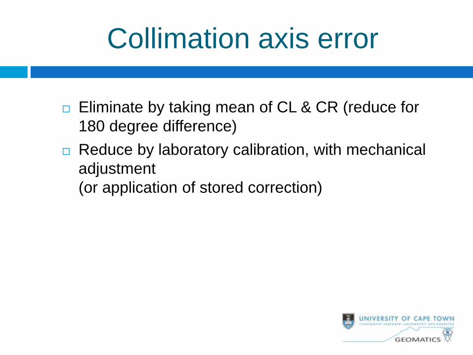
Collimation axis error
c
ce
sin z
csin e sin 90
sin c sin z
ec
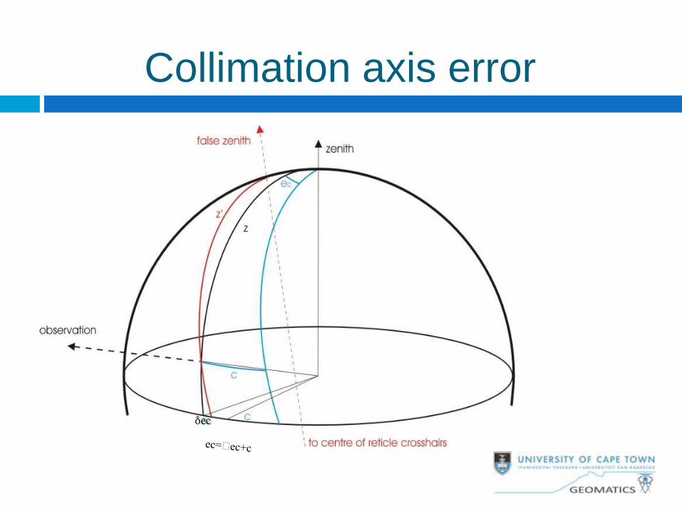
Collimation axis error
Collimation axis error
minimum of "c" at horizon,
maximum (undefined) at zenith
Collimation axis error
Eliminate by taking mean of CL & CR (reduce for
180 degree difference)
Reduce by laboratory calibration, with mechanical
adjustment
(or application of stored correction)
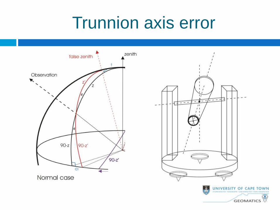
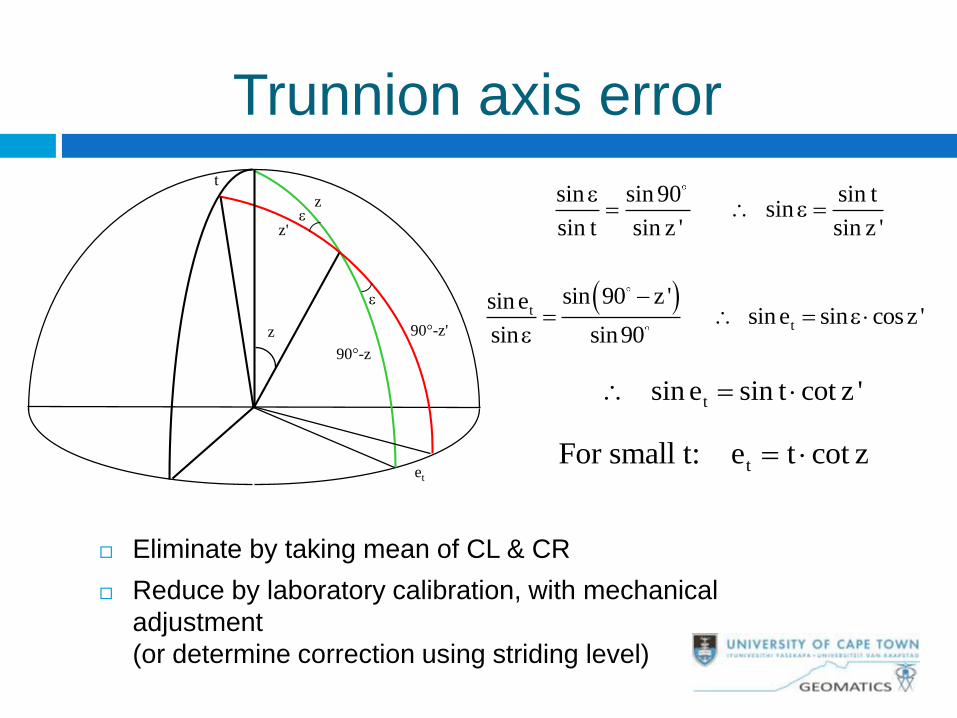
Trunnion axis error
Trunnion axis error
Eliminate by taking mean of CL & CR
Reduce by laboratory calibration, with mechanical
adjustment
(or determine correction using striding level)
t
90°-z
90°-z'
z
z'
e
e
et
z
sin sin 90 sin t sin
sin t sin z ' sin z '
e e
t
t
sin 90 z 'sin e sin e sin cosz '
sin sin90
e
e
t sin e sin t cot z '
tFor small t: e t cot z
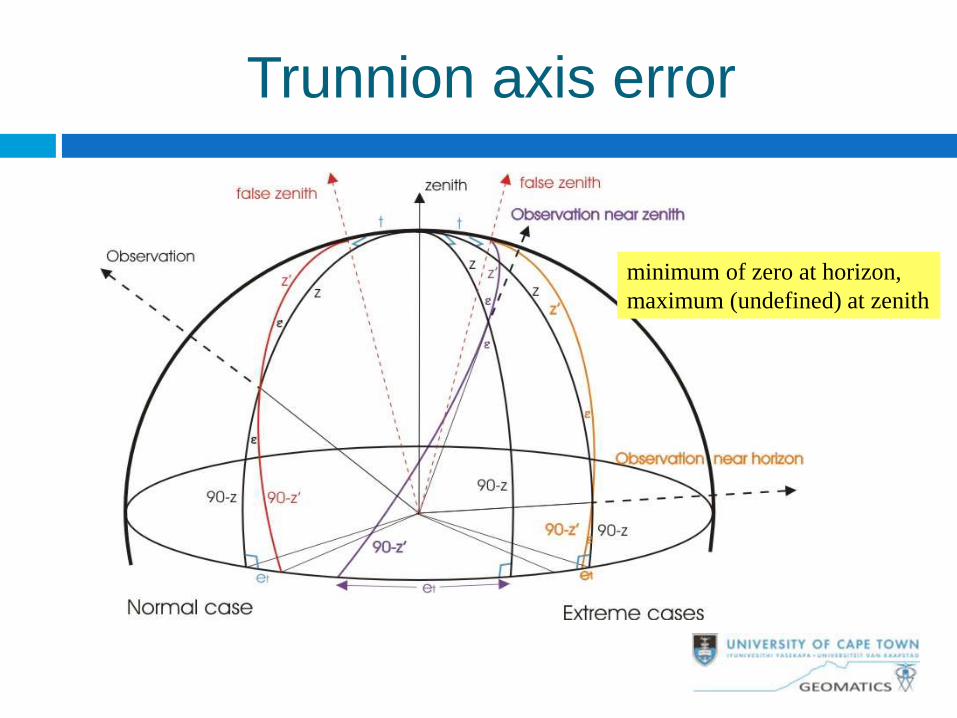
Trunnion axis error
minimum of zero at horizon,
maximum (undefined) at zenith
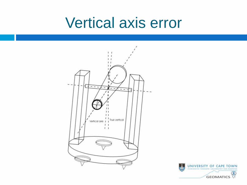
Vertical axis error
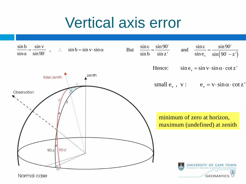
Vertical axis error
sin b sin v , sin b sin v sin
sin sin90
v
sin sin 90 sin sin 90But and
sin b sin z ' sin e sin 90 z '
e e
vHence: sin e sin v sin cot z '
v vFor small e , v : e v sin cot z '
minimum of zero at horizon,
maximum (undefined) at zenith
Vertical axis error
Reduce by careful leveling (use vertical circle
indexing device)
Reduce using vertical axis tilt sensor
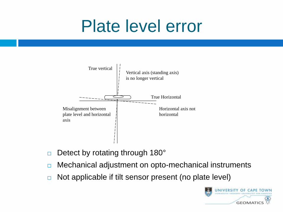
Plate level error
Detect by rotating through 180°
Mechanical adjustment on opto-mechanical instruments
Not applicable if tilt sensor present (no plate level)
Vertical axis (standing axis)
is no longer vertical
True vertical
Horizontal axis not
horizontal
True Horizontal
Misalignment between
plate level and horizontal
axis
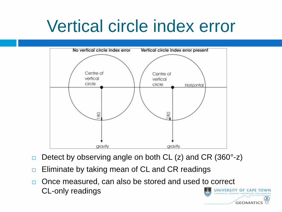
Vertical circle index error
Detect by observing angle on both CL (z) and CR (360°-z)
Eliminate by taking mean of CL and CR readings
Once measured, can also be stored and used to correct
CL-only readings
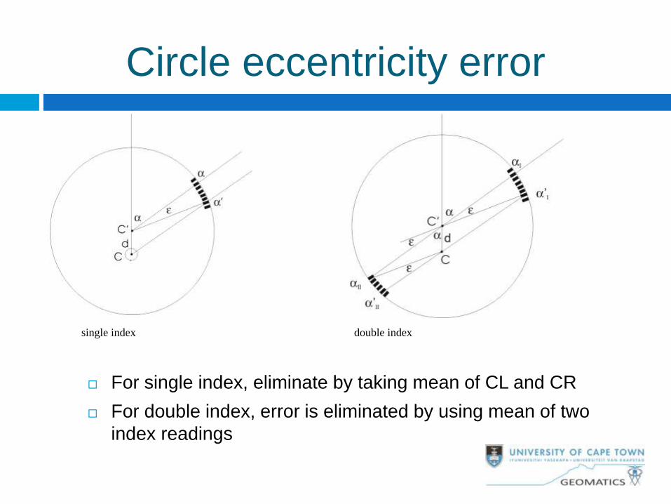
Circle eccentricity error
For single index, eliminate by taking mean of CL and CR
For double index, error is eliminated by using mean of two
index readings
single index double index
Circle graduation errors
Random errors are small and insignificant
Periodic errors are generated in circle manufacture –
periodicity depends upon the manufacturing technique.
Effect can be reduced by observing on different parts of
the circle – only possible for opto-mechanical instruments
where the circle can be rotated. In some electronic
theodolites the entire circle is sampled for a single
measurement and the effect is averaged out.
Interpolation errors occur in electronic theodolites due to a
mismatch between coarse and fine reading systems. Can
be calibrated and applied as a correction (generally only
by the manufacturer)
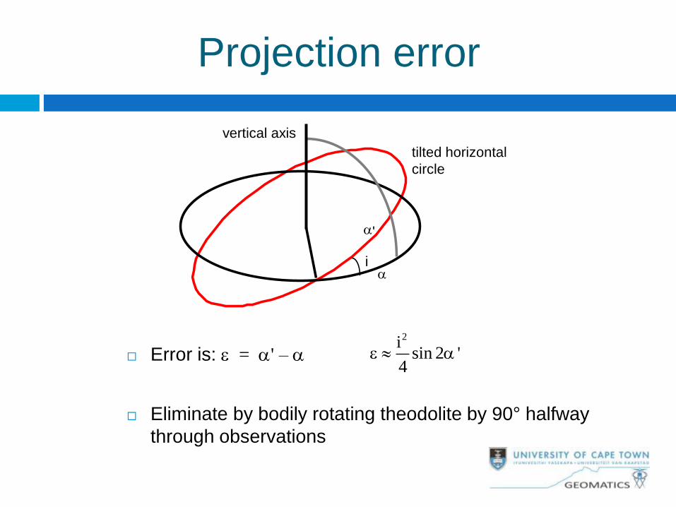
Projection error
Error is: e = ' –
Eliminate by bodily rotating theodolite by 90° halfway
through observations
vertical axis
tilted horizontal
circle
i
'
2isin 2 '
4e
Centreing
Plumbbob: low accuracy, affected by
wind
Optical plummet: requires iteration
with levelling;
if eyepiece is in tribrach it is difficult to
calibrate and adjust.
right-angle prism
eyepiece
survey mark
tribrach
right-angle
prism laser
survey mark
tribrach
Laser plummet: optics
above the tribrach, so can
be checked easily
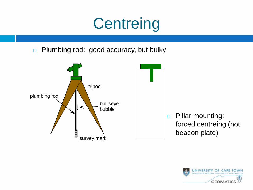
Centreing
Plumbing rod: good accuracy, but bulky
Pillar mounting:
forced centreing (not
beacon plate)
tripod
bull'seye bubble
survey mark
plumbing rod
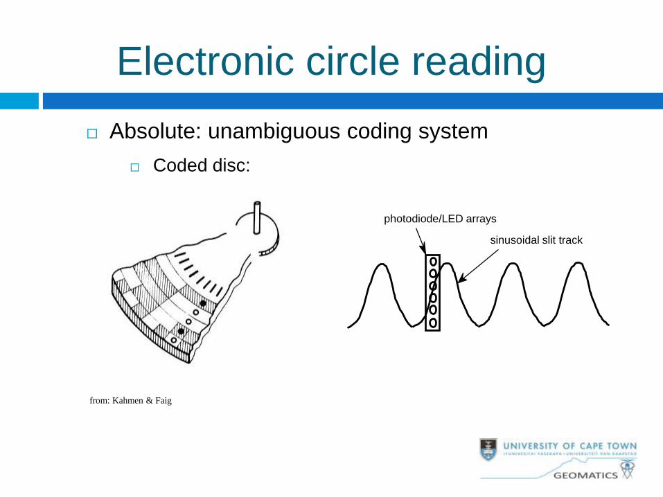
Electronic circle reading
Absolute: unambiguous coding system
Coded disc:
photodiode/LED arrays
sinusoidal slit track
from: Kahmen & Faig
Electronic circle reading
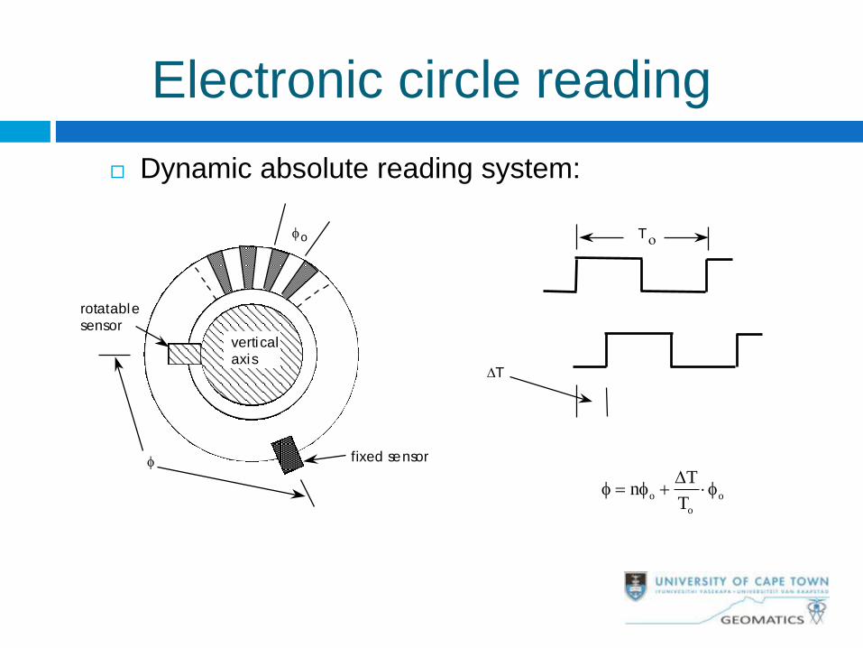
Dynamic absolute reading system:
vertical axis
fixed sensor
rotatable sensor
o
DT
To
o o
o
Tn
T
D
Electronic circle reading
+ =
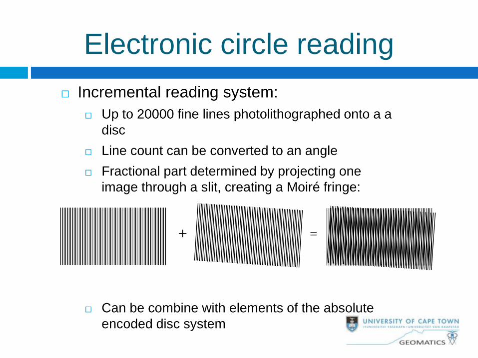
Incremental reading system:
Up to 20000 fine lines photolithographed onto a a
disc
Line count can be converted to an angle
Fractional part determined by projecting one
image through a slit, creating a Moiré fringe:
Can be combine with elements of the absolute
encoded disc system
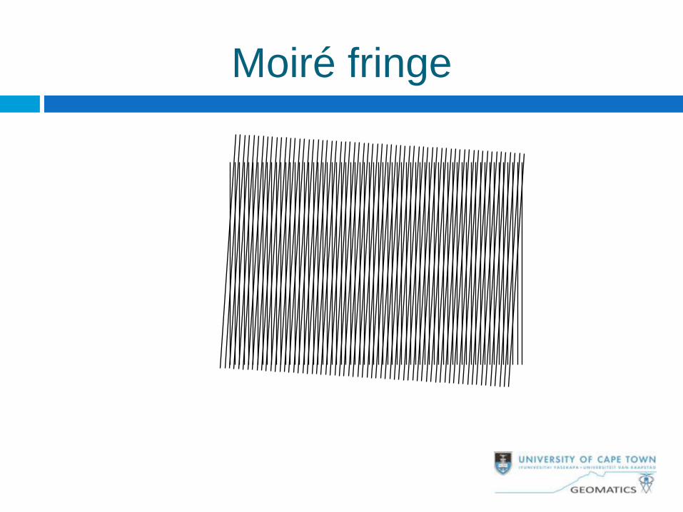
Moiré fringe
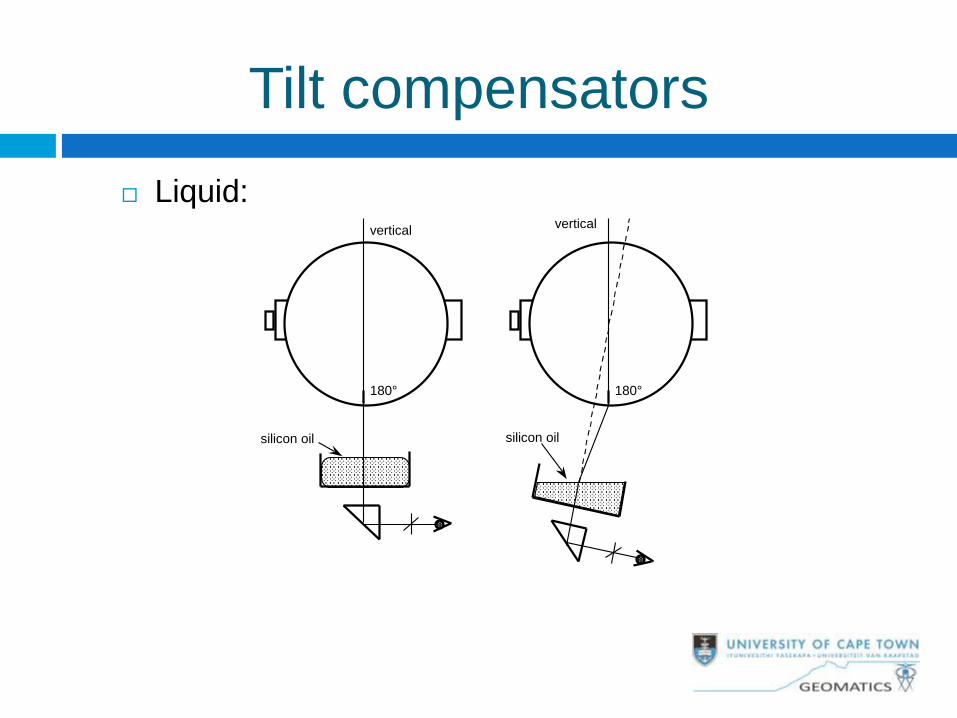
Tilt compensators
Liquid:
180°
vertical
silicon oil
180°
vertical
silicon oil
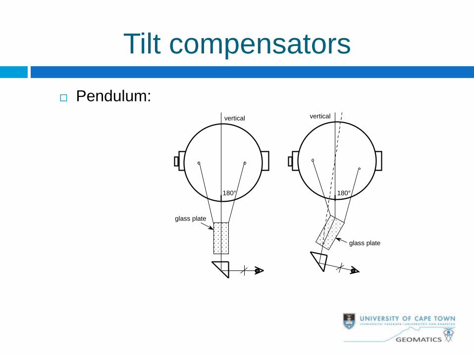
Tilt compensators
Pendulum:
180°
vertical
glass plate
180°
vertical
glass plate
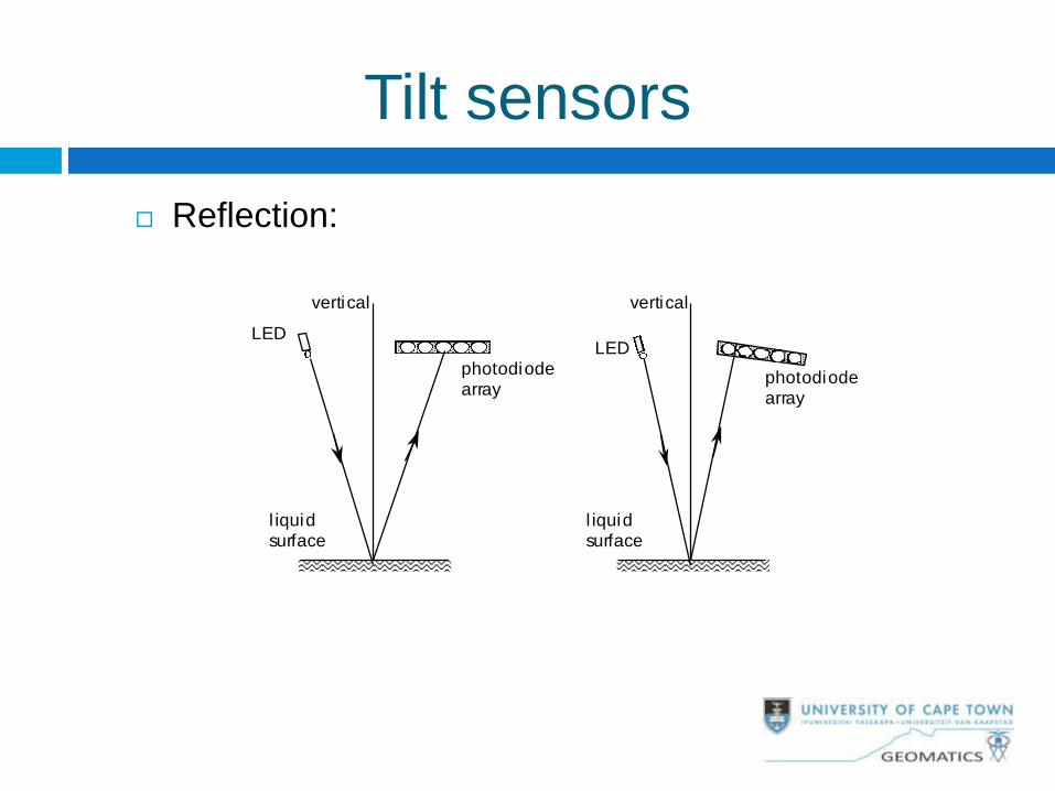
Tilt sensors
Reflection:
vertical
LED
photodiode array
l iquid surface
vertical
LED
photodiode array
l iquid surface
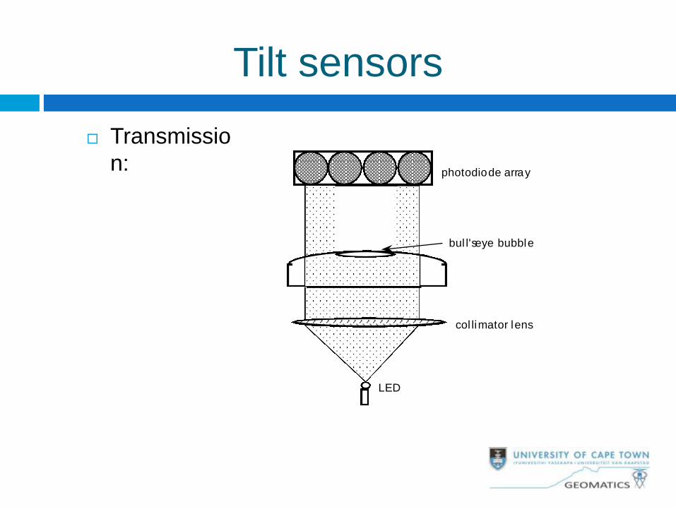
Tilt sensors
Transmissio
n:photodiode array
LED
col limator lens
bul l'seye bubble
General observing tips for high
accuracy Level and centre accurately; shade the instrument;
allow the tilt sensor time to stabilise.
Always observe on CL and CR
Observe horizontal directions separately from zenith
angles and distances
Observe multiple arcs, changing circle settings
where possible
Complete all zenith angles measurements to one
target, before observing the next
Observe RO, but only as a check (do not adjust)
Module 4: EDM and Errors30
Principles
Basic Components
Errors in EDM
Calibration of EDM
Observation Procedures and Reductions
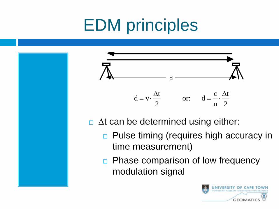
EDM principles
Dt can be determined using either:
Pulse timing (requires high accuracy in
time measurement)
Phase comparison of low frequency
modulation signal
d
t c td v or: d
2 n 2
D D
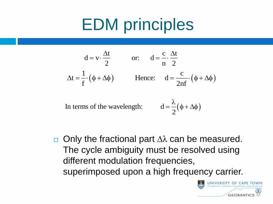
EDM principles
Only the fractional part Dλ can be measured.
The cycle ambiguity must be resolved using
different modulation frequencies,
superimposed upon a high frequency carrier.
t c td v or: d
2 n 2
D D
1 c
t Hence: df 2nf
D D D
In terms of the wavelength: d2
D
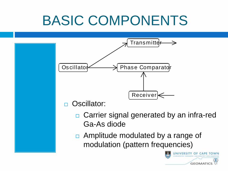
BASIC COMPONENTS
Oscillator:
Carrier signal generated by an infra-red
Ga-As diode
Amplitude modulated by a range of
modulation (pattern frequencies)
Osci l lator
Transmitter
Phase Comparator
Receiver
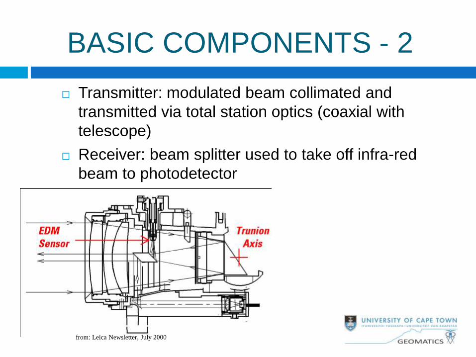
BASIC COMPONENTS - 2
Transmitter: modulated beam collimated and
transmitted via total station optics (coaxial with
telescope)
Receiver: beam splitter used to take off infra-red
beam to photodetector
from: Leica Newsletter, July 2000
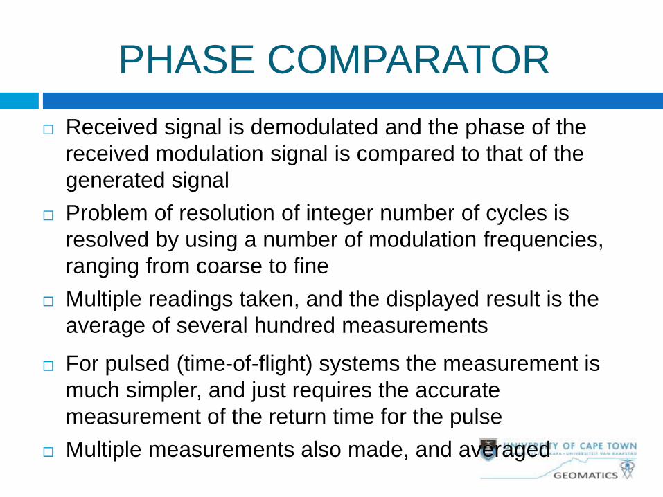
PHASE COMPARATOR
Received signal is demodulated and the phase of the
received modulation signal is compared to that of the
generated signal
Problem of resolution of integer number of cycles is
resolved by using a number of modulation frequencies,
ranging from coarse to fine
Multiple readings taken, and the displayed result is the
average of several hundred measurements
For pulsed (time-of-flight) systems the measurement is
much simpler, and just requires the accurate
measurement of the return time for the pulse
Multiple measurements also made, and averaged
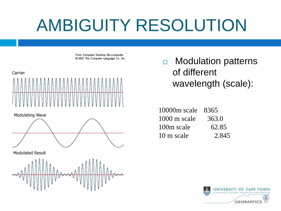
AMBIGUITY RESOLUTION
Modulation patterns
of different
wavelength (scale):
10000m scale 8365
1000 m scale 363.0
100m scale 62.85
10 m scale 2.845
PHASE vs PULSE
MEASUREMENTS Pulse (ToF) units use low power laser infra-red,
phase units do not necessarily use lasers
Phase comparison is more accurate
Pulsed systems have greater range
Hand-held laser ranging and reflectorless ranging
use pulsed laser
Most high-end models use both pulsed and phase
comparison in the same unit (pulsed for
reflectorless, phase with reflectors, and for
greater accuracy)
Errors and biases in EDM
Zero Constants
Propagation of errors
Multipath
Scale factor and determination with
zero constant
Cyclic error
ATR errors
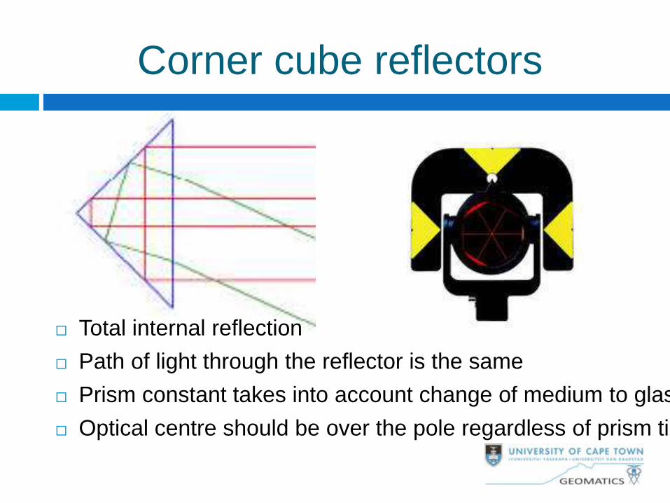
Corner cube reflectors
Total internal reflection
Path of light through the reflector is the same
Prism constant takes into account change of medium to glass
Optical centre should be over the pole regardless of prism tilt
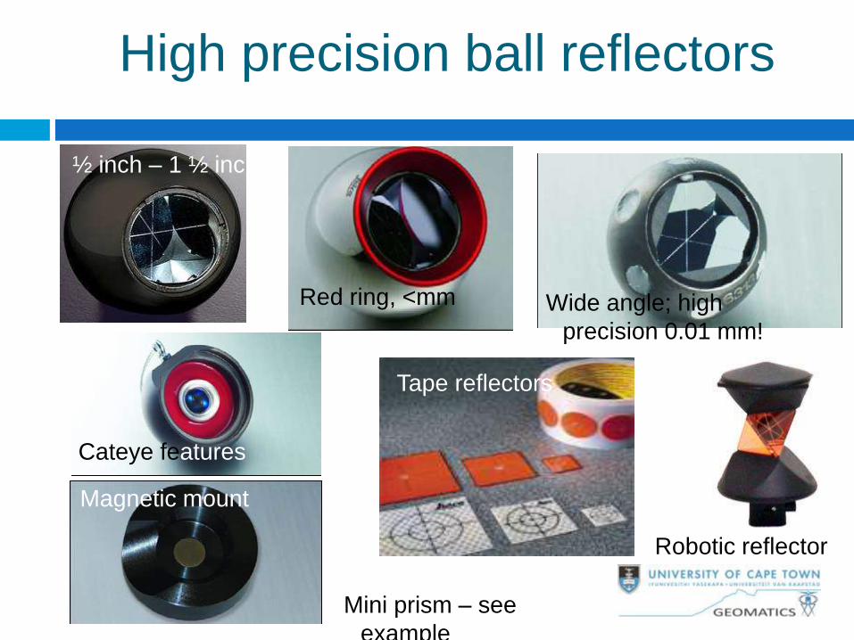
High precision ball reflectors
Red ring, <mm
½ inch – 1 ½ inch
Wide angle; high
precision 0.01 mm!
Magnetic mount
Cateye features
Tape reflectors
Robotic reflector
Mini prism – see
example
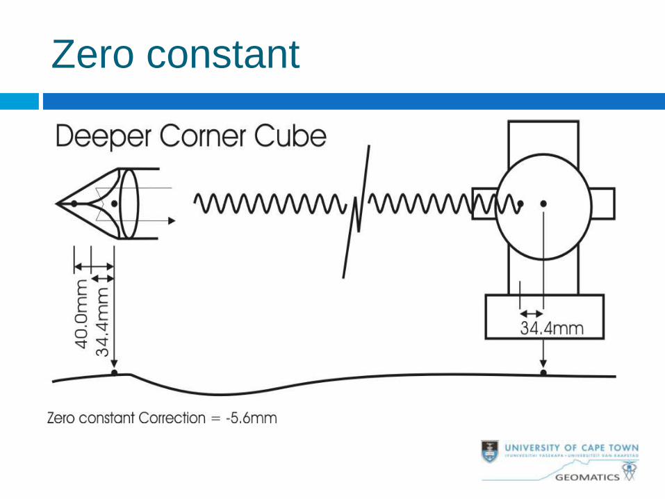
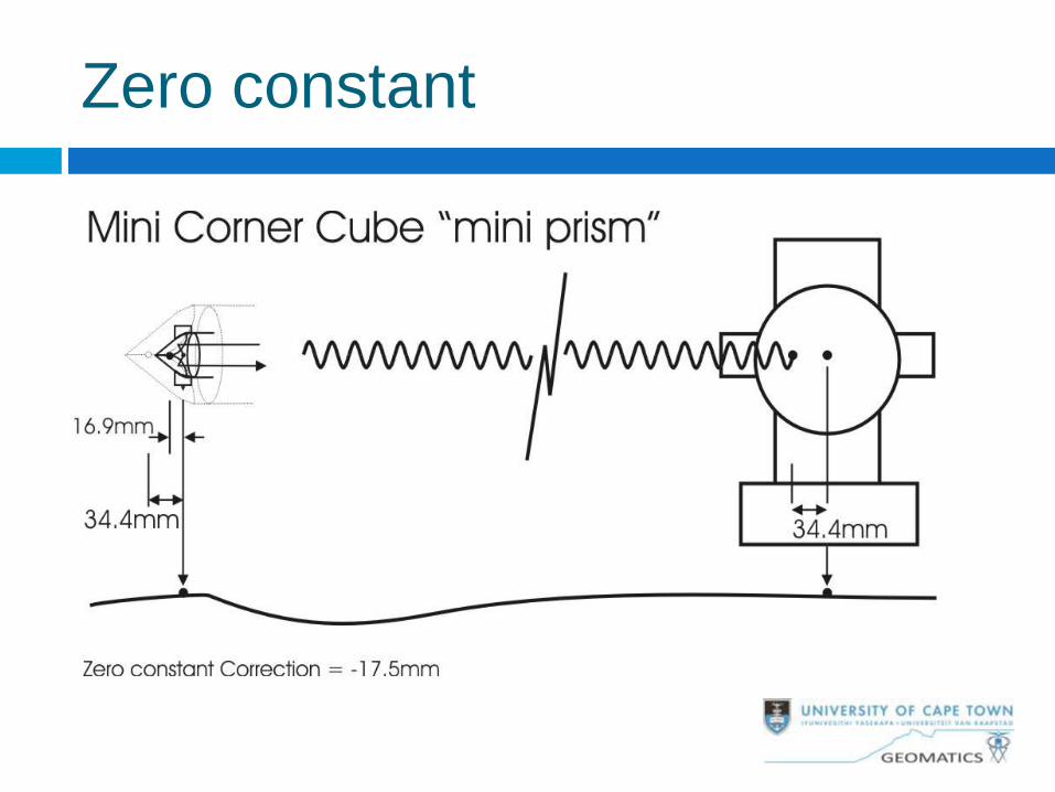
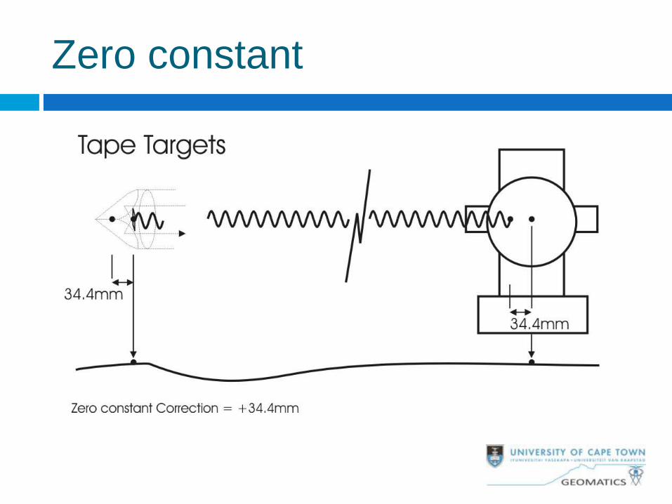
Zero constant
Is a combination of two offsets:
between electrical centre and
mechanical centre of the instrument
between point of reflection and
mechanical centre of reflector
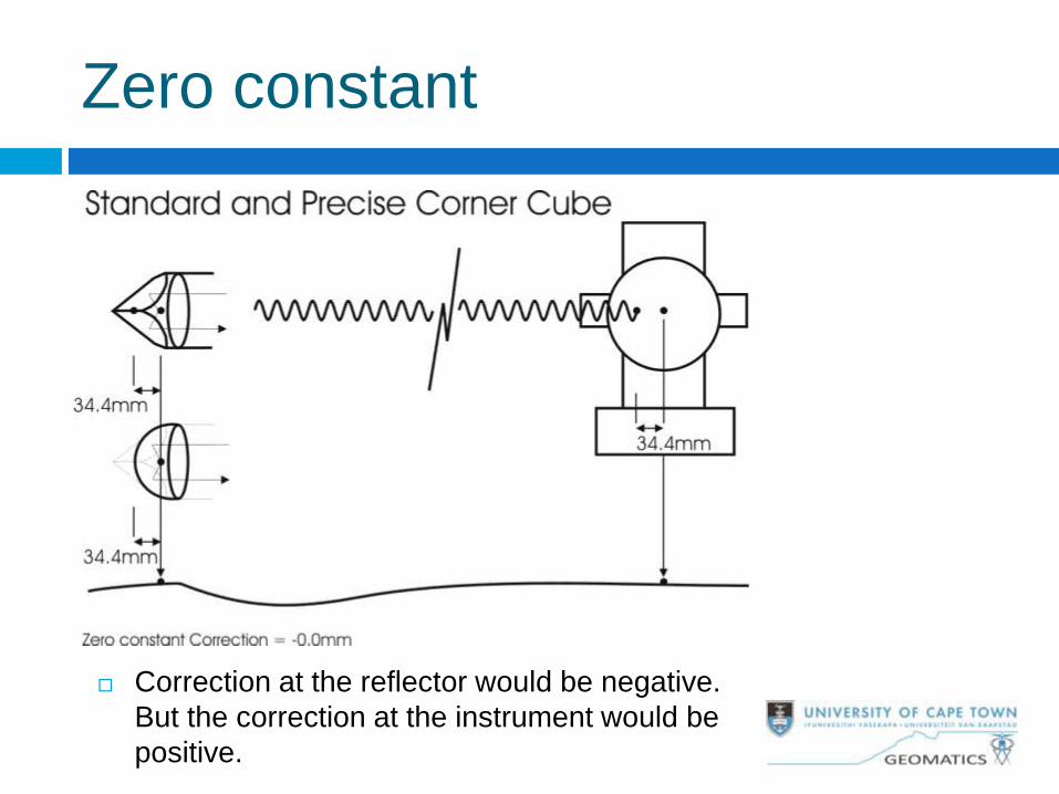
Zero constant
Correction at the reflector would be negative.
But the correction at the instrument would be
positive.
Zero constant
Zero constant
Zero constant
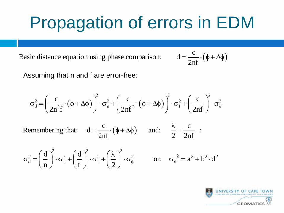
Propagation of errors in EDM
c
Basic distance equation using phase comparison: d2nf
D
2 2 2
2 2 2 2
d n f2 2
c c c
2n f 2nf 2nf
D D
Assuming that n and f are error-free:
c c
Remembering that: d and: :2nf 2 2nf
D
2 2 2
22 2 2 2 2 2 2
d n f d
d d or: a b d
n f 2
d
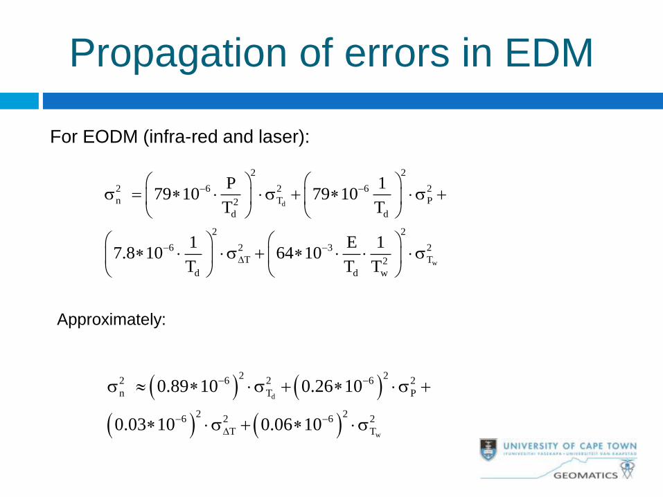
w
2 2
2 6 2 6 2
n T P2
d d
2 2
6 2 3 2
T T2
d d w
P 179 10 79 10
T T
1 E 17.8 10 64 10
T T T
D
Approximately:
d
w
2 22 6 2 6 2
n T P
2 26 2 6 2
T T
0.89 10 0.26 10
0.03 10 0.06 10
D
For EODM (infra-red and laser):
Propagation of errors in EDM
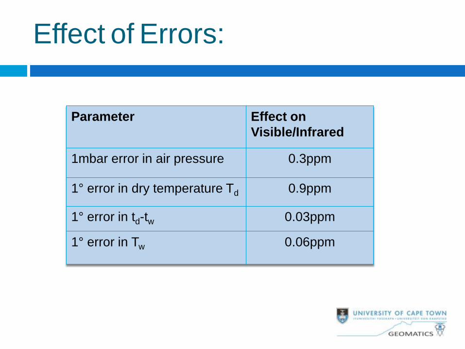
Effect of Errors:
Parameter Effect on
Visible/Infrared
1mbar error in air pressure 0.3ppm
1° error in dry temperature Td 0.9ppm
1° error in td-tw 0.03ppm
1° error in Tw 0.06ppm
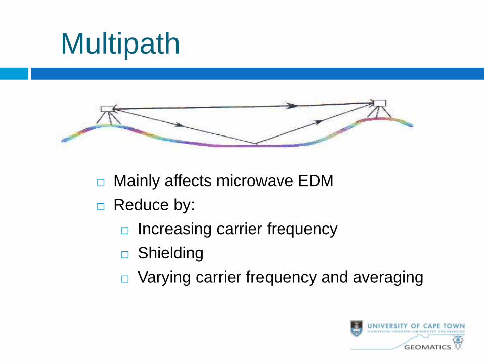
Multipath
Mainly affects microwave EDM
Reduce by:
Increasing carrier frequency
Shielding
Varying carrier frequency and averaging
Scale error
Systematic error in refractive index (suspected
for microwave EDM)
Error in reference frequency
Scale bias with respect to existing survey
control
Scale factor must be determined by field
calibration over a known baseline
Best to use several baselines of significantly
greater accuracy than the EDM
Best to use long baselines, to reduce effect
of centreing errors
Zero constant determination
Due to a combination of offsets at instrument
and reflector (different for every
instrument/reflector combination)
Can be determined from a single measurement
on a known baseline (if no scale error present)
Can be determined from three measured
distances (in a straight line) – see next slide
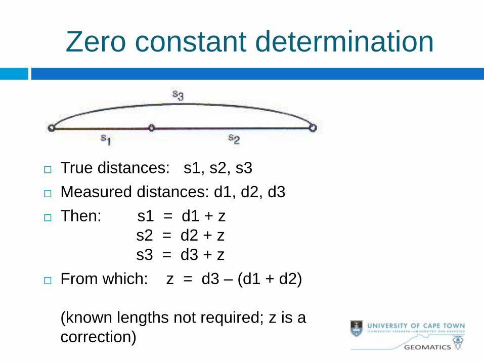
True distances: s1, s2, s3
Measured distances: d1, d2, d3
Then: s1 = d1 + z
s2 = d2 + z
s3 = d3 + z
From which: z = d3 – (d1 + d2)
(known lengths not required; z is a
correction)
Zero constant determination
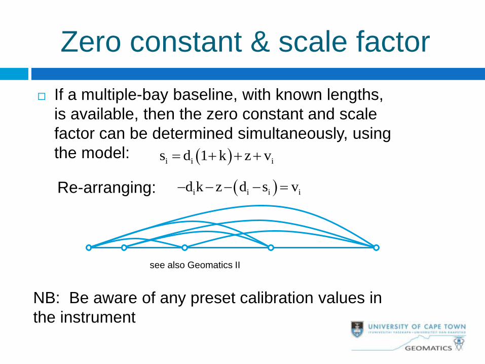
Zero constant & scale factor
If a multiple-bay baseline, with known lengths,
is available, then the zero constant and scale
factor can be determined simultaneously, using
the model: i i is d 1 k z v
Re-arranging: i i i id k z d s v
NB: Be aware of any preset calibration values in
the instrument
see also Geomatics II
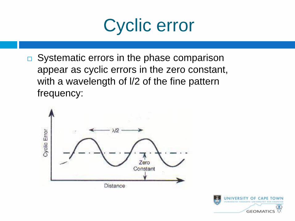
Cyclic error
Systematic errors in the phase comparison
appear as cyclic errors in the zero constant,
with a wavelength of l/2 of the fine pattern
frequency:
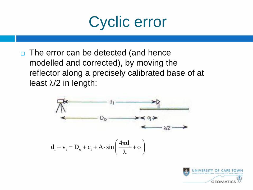
The error can be detected (and hence
modelled and corrected), by moving the
reflector along a precisely calibrated base of at
least λ/2 in length:
ii i o i
4 dd v D c A sin
Cyclic error
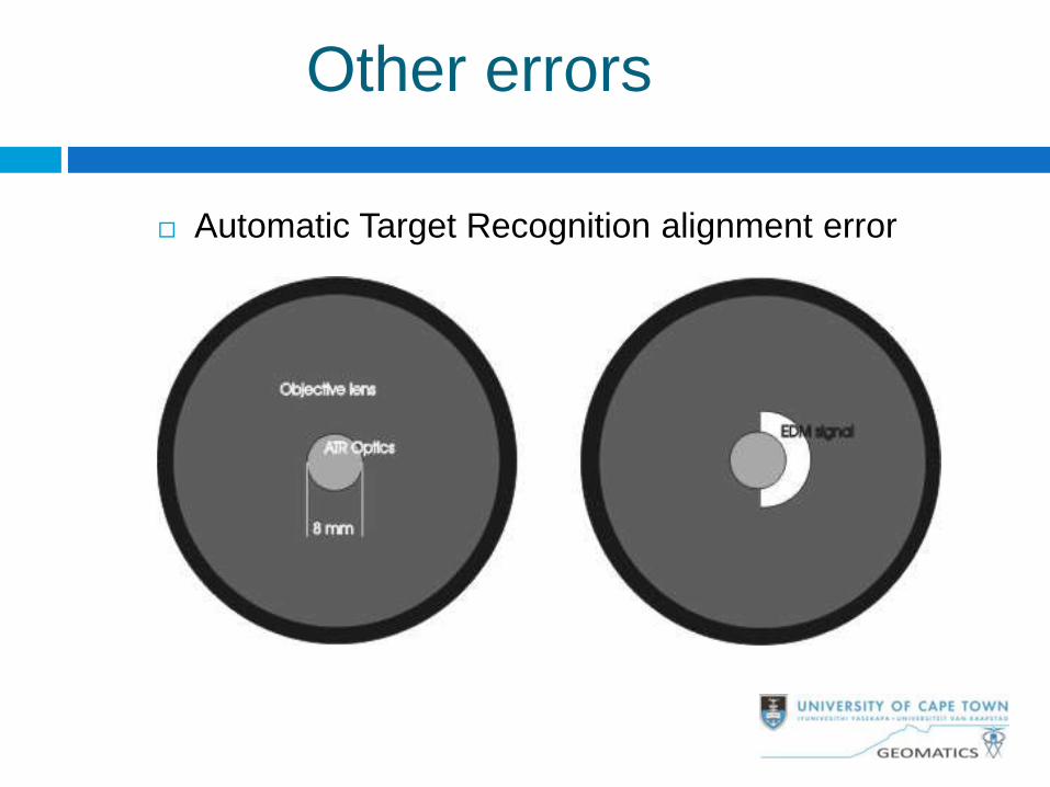
Other errors
Automatic Target Recognition alignment error
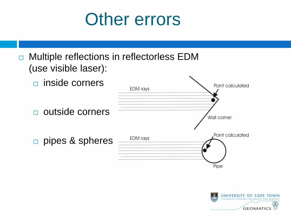
Multiple reflections in reflectorless EDM
(use visible laser):
inside corners
outside corners
pipes & spheres
Other errors
Observation precautions
Do not point at sun!
Be aware of reflective surface for reflectorless EDM
Avoid multipath conditions for microwave EDM
Check instrument settings (zero constant, scale
factor, refractive index, default temperature &
pressure)
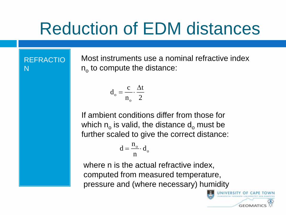
Reduction of EDM distances
Most instruments use a nominal refractive index
no to compute the distance:
o
o
c td
n 2
D
If ambient conditions differ from those for
which no is valid, the distance do must be
further scaled to give the correct distance:
oo
nd d
n
where n is the actual refractive index,
computed from measured temperature,
pressure and (where necessary) humidity
REFRACTIO
N
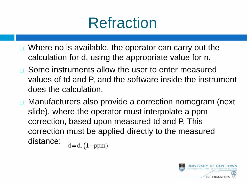
Refraction
Where no is available, the operator can carry out the
calculation for d, using the appropriate value for n.
Some instruments allow the user to enter measured
values of td and P, and the software inside the instrument
does the calculation.
Manufacturers also provide a correction nomogram (next
slide), where the operator must interpolate a ppm
correction, based upon measured td and P. This
correction must be applied directly to the measured
distance: od d 1 ppm
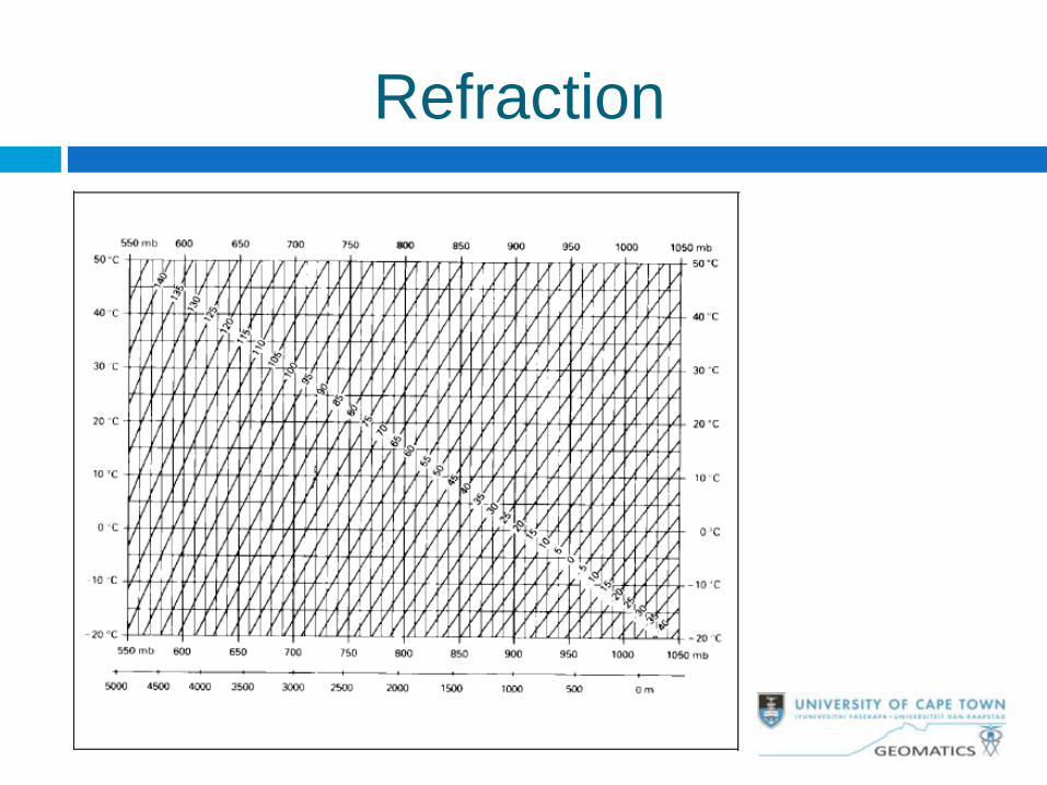
Refraction
NB: It is especially important to apply a correction to the
nominal distance when operating at altitude, as the
nominal refractive index is based upon a sea level
pressure.
E.g., at an altitude of 1500m the ppm correction to the
nominal distance is 50ppm for Leica EDM
Refraction
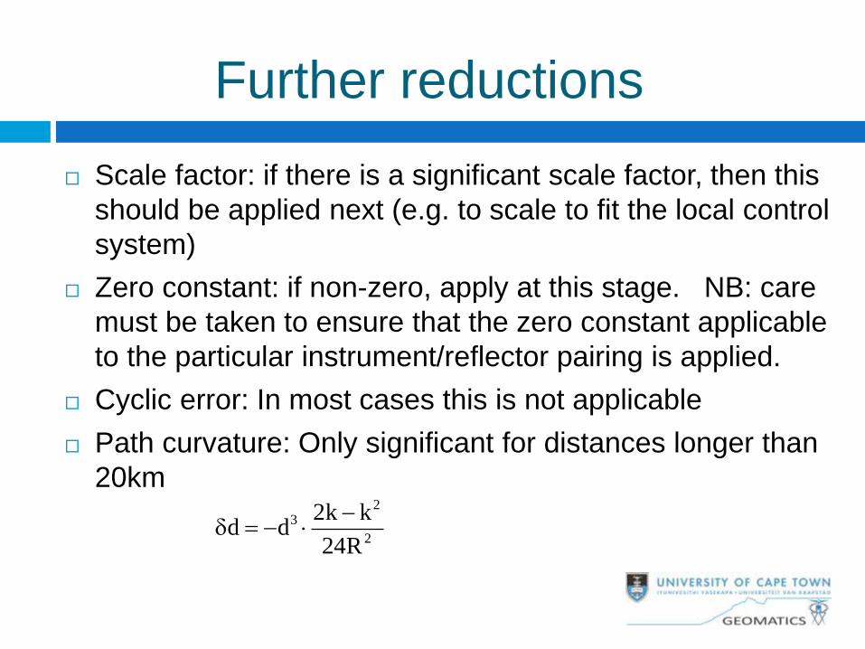
Further reductions
Scale factor: if there is a significant scale factor, then this
should be applied next (e.g. to scale to fit the local control
system)
Zero constant: if non-zero, apply at this stage. NB: care
must be taken to ensure that the zero constant applicable
to the particular instrument/reflector pairing is applied.
Cyclic error: In most cases this is not applicable
Path curvature: Only significant for distances longer than
20km 2
3
2
2k kd d
24R
Reduction to computing surface
After application of the corrections listed, we now
have a straight line in space.
Reduction to the computing surface (ellipsoid or
plane) involves reductions for slope, height above
ellipsoid and scale enlargement (if the computing
surface is the projection plane).
For greater precision, the first two steps are
combined into one (see next slide)
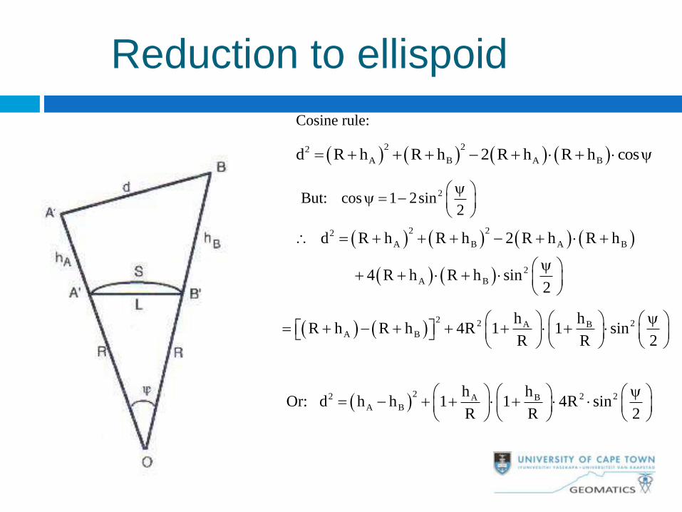
Cosine rule:
2 22
A B A Bd R h R h 2 R h R h cos
2But: cos 1 2sin2
2 22
A B A B
2
A B
d R h R h 2 R h R h
4 R h R h sin2
2 2 2A B
A B
h hR h R h 4R 1 1 sin
R R 2
22 2 2A B
A B
h hOr: d h h 1 1 4R sin
R R 2
Reduction to ellispoid
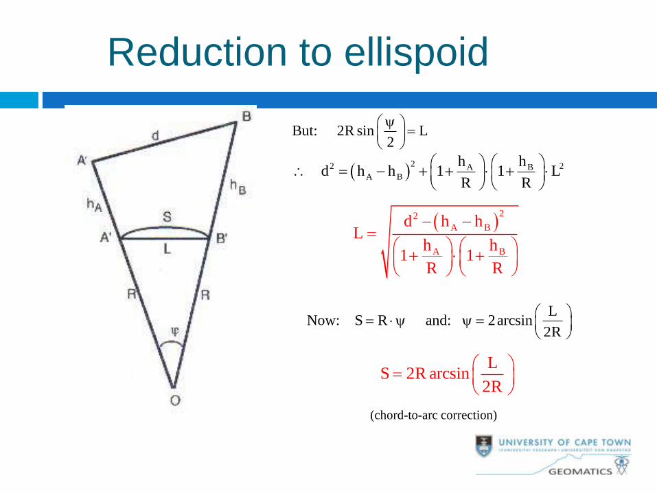
But: 2R sin L2
22 2A B
A B
h h d h h 1 1 L
R R
22
A B
A B
d h hL
h h1 1
R R
LNow: S R and: 2arcsin
2R
LS 2R arcsin
2R
(chord-to-arc correction)
Reduction to ellispoid
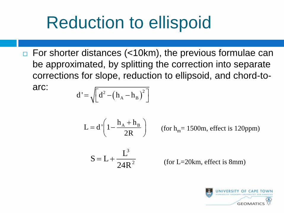
For shorter distances (<10km), the previous formulae can
be approximated, by splitting the correction into separate
corrections for slope, reduction to ellipsoid, and chord-to-
arc:
22
A Bd ' d h h
A Bh hL d ' 1
2R
3
2
LS L
24R
(for hm= 1500m, effect is 120ppm)
(for L=20km, effect is 8mm)
Reduction to ellispoid
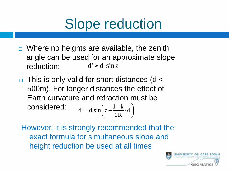
Slope reduction
Where no heights are available, the zenith
angle can be used for an approximate slope
reduction: d' d sinz
This is only valid for short distances (d <
500m). For longer distances the effect of
Earth curvature and refraction must be
considered: 1 kd ' d.sin z d
2R
However, it is strongly recommended that the
exact formula for simultaneous slope and
height reduction be used at all times
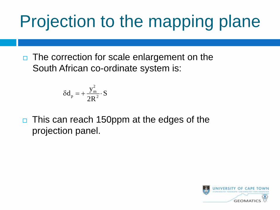
Projection to the mapping plane
The correction for scale enlargement on the
South African co-ordinate system is:
2
mp 2
yd S
2R
This can reach 150ppm at the edges of the
projection panel.


