
YEB PNT Advisory Board, June 2011
Geodetic Reference Antenna in Space (GRASP):
A Mission to Enhance GNSS and the Terrestrial Reference Frame Yoaz Bar-Sever, Willy Bertiger, Shailen Desai, Richard Gross, Bruce Haines, Sien Wu, JPL
Steve Nerem, University of Colorado , Boulder
1

YEB PNT Advisory Board, June 2011
GRASP Mission Goals
The GRASP mission concept is designed to address the following problems: • Establishing precise and stable ties between the geodetic techniques used to define
and disseminate the TRF • Consistently calibrate the myriad antennas used to transmit and receive GNSS
signals, in ground and space applications • Enhance the contribution of GNSS to the TRF, and further improve the accuracy and
stability of the TRF • Improve the overall accuracy of GNSS orbit and clock states, benefiting all precision
GNSS applications • And more…
With thousands of tracking sites globally, GNSS is the primary technique for densifying, transferring, and accessing the Terrestrial Reference Frame (TRF)
2
YEB PNT Advisory Board, June 2011
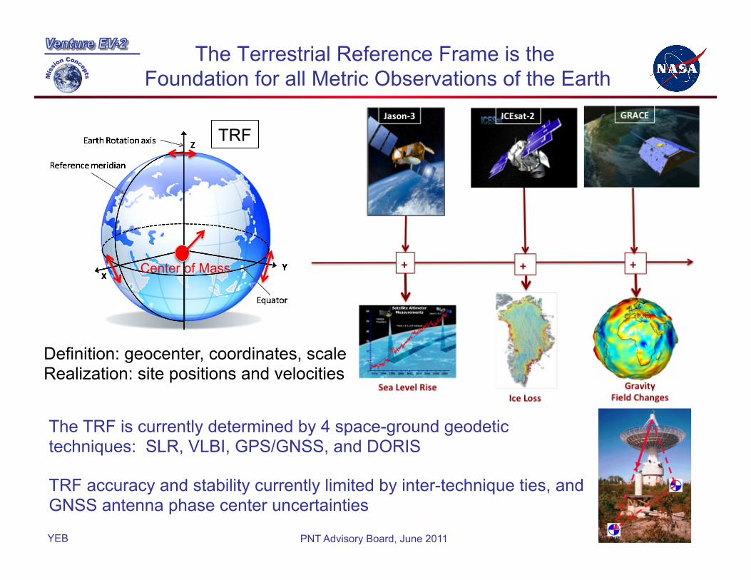
The Terrestrial Reference Frame is the Foundation for all Metric Observations of the Earth
3
The TRF is currently determined by 4 space-ground geodetic techniques: SLR, VLBI, GPS/GNSS, and DORIS TRF accuracy and stability currently limited by inter-technique ties, and GNSS antenna phase center uncertainties
Center of Mass
TRF
Definition: geocenter, coordinates, scale Realization: site positions and velocities
YEB PNT Advisory Board, June 2011
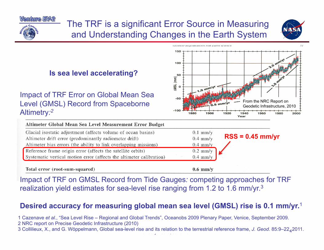
The TRF is a significant Error Source in Measuring and Understanding Changes in the Earth System
Is sea level accelerating?
Impact of TRF Error on Global Mean Sea Level (GMSL) Record from Spaceborne Altimetry:2
1 Cazenave et al., “Sea Level Rise – Regional and Global Trends”, Oceanobs 2009 Plenary Paper, Venice, September 2009. 2 NRC report on Precise Geodetic Infrastructure (2010) 3 Collilieux, X., and G. Wöppelmann, Global sea-level rise and its relation to the terrestrial reference frame, J. Geod. 85:9–22, 2011.
Impact of TRF on GMSL Record from Tide Gauges: competing approaches for TRF realization yield estimates for sea-level rise ranging from 1.2 to 1.6 mm/yr.3 Desired accuracy for measuring global mean sea level (GMSL) rise is 0.1 mm/yr.1
RSS = 0.45 mm/yr
From the NRC Report on Geodetic Infrastructure, 2010
4

YEB PNT Advisory Board, June 2011
Uncertainty in GPS Antenna Phase Variations is a Limiting Error Source in GPS-Geodesy
Evidence of a problem: • High post-fit residuals for GPS43 (1st IIR sat) • Bias in Topex GPS antenna position • Drift in Jason GPS antenna position • Drift in GPS realization of TRF Scale Error is phase center => error is position
TRF Scale from GPS Alone (2002–2007): Agreement with ITRF2005
-20
0
20
40
60
-4
-2
0
2
4
6
8
2002 2003 2004 2005 2006 2007 2008
mm
ppb
Years
+0.01 ppb/yr
–0.21 ppb/yr
–0.37 ppb/yr
This Study vs. ITRF2005IGT05
Legacy vs. ITRF2005IGT05
Legacy vs. ITRF2000JPL00
-100
-50
0
50
100
-12
-8
-4
0
4
8
12
1994.0 1996.0 1998.0 2000.0 2002.0 2004.0 2006.0
Time Series of T/P and Jason-1 Radial Antenna Offset EstimatesNoneIGSJPLBCDBCD
Nominal (Gipsy) Model
GRACE-Based GPS PCV Maps
mm
ppb
Year
TOPEX/Poseidon Jason-1
GRACE Data SpanUsed In
PCV Maps
D
-8.2953701Minimum
8.5058155Maximum
0.60300648Sum
19Points
0.031737183Mean
1.1129774Median
4.6419038RMS
4.7689914Std Deviation
22.743279Variance
1.0940817Std Error
-0.039184551Skewness
-0.92282638Kurtosis
Slope = +3.7 ± 0.1 mm/yr
Slope = +0.1 ± 0.1 mm/yr
Bias = +55.6 ± 0.8 mm
B
48.259182Minimum
60.715157Maximum
1056.7383Sum
19Points
55.617803Mean
55.645386Median
55.716286RMS
3.4020173Std Deviation
11.573722Variance
0.78047629Std Error
-0.39930782Skewness
-0.57790671Kurtosis
Bias = +0.0 ± 1.1 mmJason APV map before correction for GPS transmit APV
5

YEB PNT Advisory Board, June 2011
Problems with Ground-Based Determination of the GPS Satellites Antenna Phase Variations
Estimation of GPS transmit APV from ground observations is problematic:
– Sensitivity to tropospheric delay biases
– High correlation with receiver APV, which are uncertain due to local multipath and diversity of hardware • Robot- or anechoic chamber-based antenna calibrations do not capture the conditions in-situ
• High likelihood of global systematic error because of common monument types
– Dependent on the TRF; IGS selected antenna offset to maintain the TRF Scale
– Narrow field of view limits utility for space applications
0
5
10
15
0 4 8 12 16
Sampling of GPS Transmitter Beam Pattern
TERRESTRIAL NETWORKGRACE (500 km)JASON (1300 km)
% O
bs.
Nadir Angle (Deg.)
Sampling of GPS Transmitter Beam Pattern
6

YEB PNT Advisory Board, June 2011
GRACE: GRASP Concept Experiment
• GRACE acted as the GRASP pathfinder mission
• A priori GRACE antenna model from pre-launch anechoic measurements
• GPS transmit Antenna map estimated iteratively
• Scale is derived from GM • Estimates for all PRNs flying Oct.
2006–Nov. 2009 • Includes group delay (Ionosphere-
free pseudorange, PC)
GRACE APV (LC) FROM ANECHOIC MEASUREMENTS TYPICAL GPS APV (LC) FROM
STACKED RESIDUAL APPROACH
GRACE spacecraft (500 km orbit) GPS spacecraft (20,000 km orbit)
GRACE GPS antenna phase (receive) GPS spacecraft antenna phase
(transmit) [from GRACE data]
• Proof of concept well demonstrated • But, GRASP is much better suited to
this measurement than GRACE: • Center of Mass to mm level • Better calibrated, and includes PC • 1,400 km orbit height (same as
altimetry missions: T/P, J-1,2,3) 7

YEB PNT Advisory Board, June 2011
GRASP Spacecra, Concept
CPU + DSP
DC - DC
Clk in
GNSS/VLBI
C&DH
RF Down Converters
GNSS Antenna
S-Band and X-Band
VLBI Antenna
Comm LInk - Transponder
VLBI signals
LNA
Amp
S-Band and X-band Comm Antenna
Solar Panels
Laser Retroreflector
Array
DORIS
5 Science Instruments: • GNSS • VLBI • DORIS • LRA • The spacecraft
Nadir
Sun
10 MHz ref
Orbit: 1400 km altitude, circular, sun-synchronous (~101.4°inclination) No eclipses
• Collocate all the geodetic techniques on one spacecraft • Ground calibrate all sensors to sub-mm • Design spacecraft and orbit to facilitate sub-mm POD
8
YEB PNT Advisory Board, June 2011 9
GRASP Broad Benefits
• The spacecraft is a flying geodetic super-site: – Enables the realization of the TRF with 1 mm accuracy and 0.1 mm/year stability as
specified by GGOS – Improves the measurement of sea level change and ice/water mass changes being
made by satellite altimeter and satellite gravity missions respectively. – Essentially an orbiting “measurement lab” that combines the most important
geodetic measurements on a single spacecraft. – Will complement data being collected by Jason-2/3 and GRACE Follow On. – Enhance the global geodetic infrastructure through improved inter-technique ties
• Many of the benefits of GRASP can be extended retroactively to improve the entire ~20 year altimetric sea level record and the decade-long satellite gravity record. Likewise, future altimeter and gravity measurements will benefit from GRASP as well.
• GRASP will enhance the accuracy of precision GNSS applications
• GRASP will promote interoperability of GNSS by providing a common reference

YEB PNT Advisory Board, June 2011
Simulations Demonstrate Broad GNSS Benefits
Absolute reference antenna for consistent calibration of all GNSS antennas, ground and space
– Factor of 3.5 improvement is determination of GPS antenna radial offset with GPS data alone; factor of 8 improvement with SLR data
– GNSS satellite APV sampling fully consistent with high LEO missions, such as Jason, and will improve GNSS-based orbit determination of LEOs
Factor of 3 improvement in GPS POD Factor of 10 improvement in Geocenter determination with GPS data alone
Enhances GNSS contributions to the TRF through geocenter and scale (GNSS-based scale determination not shown here) • Factor of 10 improvement in Geocenter
determination with GPS data alone
10
YEB PNT Advisory Board, June 2011
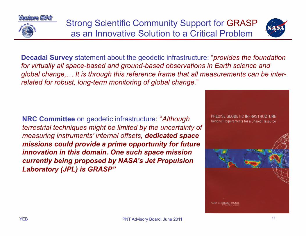
Strong Scientific Community Support for GRASP as an Innovative Solution to a Critical Problem
Decadal Survey statement about the geodetic infrastructure: “provides the foundation for virtually all space-based and ground-based observations in Earth science and global change,… It is through this reference frame that all measurements can be inter-related for robust, long-term monitoring of global change.”
NRC Committee on geodetic infrastructure: “Although terrestrial techniques might be limited by the uncertainty of measuring instruments’ internal offsets, dedicated space missions could provide a prime opportunity for future innovation in this domain. One such space mission currently being proposed by NASA’s Jet Propulsion Laboratory (JPL) is GRASP”
11
YEB PNT Advisory Board, June 2011
GRASP Programmatics
• NASA draft Venture AO released (on time) in February 2011
- $150M cap, Earth-science focused mission
• Final AO release due June 17, proposals due 3 months later
• Passed JPL Ventures review in March, 2011; now in full mission proposal mode
- PI: Prof. Steve Nerem, University of Colorado, Boulder
- Targeted launch: 2016/2017; 3 years in orbit
• This is a mission by and for the geodetic community – all data will be available to the public immediately
• Secured broad endorsements from the geodetic community: GGOS, IGS, ILRS, IDS, and IVS
• GRASP is a dual-use mission – seeking DoD endorsements and support
– Secured endorsements from GPS Directorate and USNO
12


