Download - Genie Manual de Servicio Gth-844
8/14/2019 Genie Manual de Servicio Gth-844
http://slidepdf.com/reader/full/genie-manual-de-servicio-gth-844 1/196
Parts Manual
GTH-844
GTH-842
GTH-644
after GTH05-12345
after GTH05-12345
after GTH05-12345
Serial Number Range
Service Manual
GTH-636
GTH-644
GTH-842
Part No. 97487
Rev D
June 2007
from GTH0806A-8418from GTH0806B-6958
Serial Number Range
from GTH0606A-8418
from GTH0606A-8418from GTH0606B-6271
GTH-844
GTH-1048
GTH-1056
GTH-844
from GTH1006A-8418 toGTH-1007A-11442
from GTH0806A-8418from GTH0806B-6956
from GTH1006A-8418 toGTH1007A-11442

8/14/2019 Genie Manual de Servicio Gth-844
http://slidepdf.com/reader/full/genie-manual-de-servicio-gth-844 2/196
June 2007
GTH-636 GTH-644 • GTH-842 • GTH-844 • GTH-1048 • GTH-1056 Part No. 97487ii
Introduction
Important
Read, understand and obey the safety rules and
operating instructions in the appropriate Operator'sManual on your machine before attempting any
maintenance or repair procedure.
This manual provides detailed scheduledmaintenance information for the machine owner
and user. It also provides troubleshooting andrepair procedures for qualified service
professionals.
Basic mechanical, hydraulic and electricalskills are required to perform most procedures.
However ,several procedures require specializedskills, tools, lifting equipment and a suitableworkshop. In these instances, we strongly
recommend that maintenance and repair beperformed at an authorized Genie dealer
service center.
Technical Publications
Genie Industries has endeavored to deliver the
highest degree of accuracy possible. However,continuous improvement of our products is a Genie
policy. Therefore, product specifications aresubject to change without notice.
Readers are encouraged to notify Genie of errors
and send in suggestions for improvement. Allcommunications will be carefully considered for
future printings of this and all other manuals.
Contact Us:
PO Box 97030
Redmond, WA 98073-9730 USA
www.genieindustries.com
e-mail: [email protected]
Copyright © 2006 by Genie Industries
97487 Rev D June 2007First Edition, Fourth Printing
"Genie" is a registered trademark of GenieIndustries in the USA and many other countries."GTH" is a trademark of Genie Industries.
Printed on recycled paper
Printed in U.S.A.
Introduction
8/14/2019 Genie Manual de Servicio Gth-844
http://slidepdf.com/reader/full/genie-manual-de-servicio-gth-844 3/196
June 2007
Part No. 97487 GTH-636 • GTH-644 • GTH-842 • GTH-844 • GTH-1048 • GTH-1056 iii
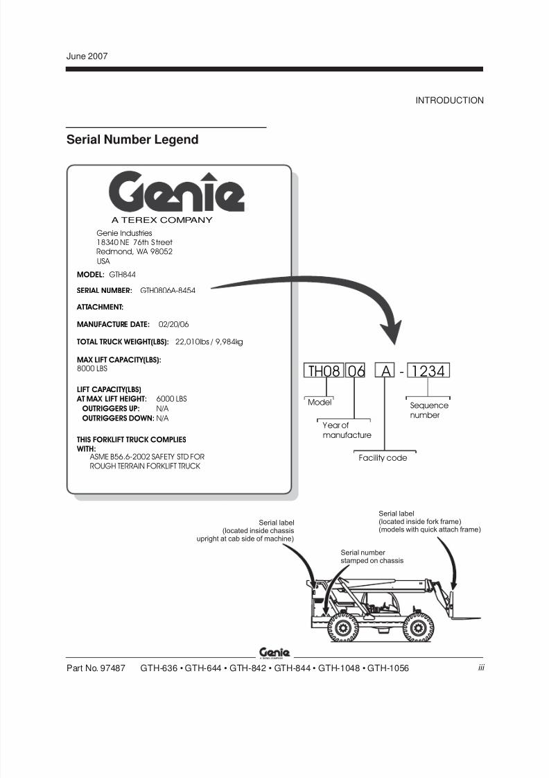
Serial Number Legend
INTRODUCTION
TH08 06 A - 1234
Model
Y ear of
manufacture
Facility code
Sequencenumber
MODEL:
Genie Industries18340 NE 76th S treetRedmond, WA 98052
USA
GTH844
A TEREX COMPANY
SERIAL NUMBER: GTH0806A-8454
ATTACHMENT:
MANUFACTURE DATE: 02/20/06
TOTAL TRUCK WEIGHT(LBS): 22,010lbs / 9,984kg
MAX LIFT CAPACITY(LBS):8000 LBS
LIFT CAPACITY(LBS)
AT MAX LIFT HEIGHT:
OUTRIGGERS UP:OUTRIGGERS DOWN: N/A
N/A
6000 LBS
THIS FORKLIFT TRUCK COMPLIES WITH:
ASME B56.6-2002 SAFETY STD FOR
ROUGH TERRAIN FORKLIFT TRUCK
Serial label(located inside fork frame)(models with quick attach frame)
Serial label(located inside chassis
upright at cab side of machine)
Serial number stamped on chassis
8/14/2019 Genie Manual de Servicio Gth-844
http://slidepdf.com/reader/full/genie-manual-de-servicio-gth-844 4/196
June 2007
GTH-636 • GTH-644 • GTH-842 • GTH-844 • GTH-1048 • GTH-1056 Part No. 97487iv
This page intentionally left blank.

8/14/2019 Genie Manual de Servicio Gth-844
http://slidepdf.com/reader/full/genie-manual-de-servicio-gth-844 5/196
June 2007
Part No. 97487 GTH-636 • GTH-644 • GTH-842 • GTH-844 • GTH-1048 • GTH-1056
Safety Rules
Section 1 • Safety Rules
v
Danger
Failure to obey the instructions and safety rules
in this manual and the appropriate Operator'sManual on your machine will result in death or
serious injury.
Many of the hazards identified in theoperator’s manual are also safety hazardswhen maintenance and repair procedures
are performed.
Do Not Perform MaintenanceUnless:
You are trained and qualified to perform
maintenance on this machine.
You read, understand and obey:
- manufacturer’s instructions and safety rules
- employer’s safety rules and worksiteregulations
- applicable governmental regulations
You have the appropriate tools, lifting
equipment and a suitable workshop.
8/14/2019 Genie Manual de Servicio Gth-844
http://slidepdf.com/reader/full/genie-manual-de-servicio-gth-844 6/196
June 2007
GTH-636 • GTH-644 • GTH-842 • GTH-844 • GTH-1048 • GTH-1056 Part No. 97487
SAFETY RULES
vi
Section 1 • Safety Rules
Personal Safety
Any person working on or around a machine must
be aware of all known safety hazards. Personalsafety and the continued safe operation of the
machine should be your top priority.
Read each procedure thoroughly. This
manual and the decals on the machine,use signal words to identify the following:
Safety alert symbol—used to alertpersonnel to potential personal
injury hazards. Obey all safetymessages that follow this symbol
to avoid possible injury or death.
Indicates an imminently hazardoussituation which, if not avoided, will
result in death or serious injury.
Indicates a potentially hazardoussituation which, if not avoided,
could result in death or seriousinjury.
Indicates a potentially hazardous
situation which, if not avoided,may cause minor or moderate
injury.
Indicates a potentially hazardoussituation which, if not avoided,
may result in property damage.
Be sure to wear protective eye wear andother protective clothing if the situation
warrants it.
Be aware of potential crushing hazardssuch as moving parts, free swinging or
unsecured components when lifting orplacing loads. Always wear approvedsteel-toed shoes.
Workplace SafetyBe sure to keep sparks, flames andlighted tobacco away from flammable and
combustible materials like battery gasesand engine fuels. Always have anapproved fire extinguisher within easy
reach.
Be sure that all tools and working areasare properly maintained and ready foruse. Keep work surfaces clean and free of
debris that could get into machinecomponents and cause damage.
Be sure any forklift, overhead crane or
other lifting or supporting device is fullycapable of supporting and stabilizing theweight to be lifted. Use only chains or
straps that are in good condition and ofample capacity.
Be sure that fasteners intended for onetime use (i.e., cotter pins and self-locking
nuts) are not reused. These componentsmay fail if they are used a second time.
Be sure to properly dispose of old oil orother fluids. Use an approved container.
Please be environmentally safe.
Be sure that your workshop or work areais properly ventilated and well lit.

8/14/2019 Genie Manual de Servicio Gth-844
http://slidepdf.com/reader/full/genie-manual-de-servicio-gth-844 7/196
June 2007
Part No. 97487 GTH-636 • GTH-644 • GTH-842 • GTH-844 • GTH-1048 • GTH-1056
Table of Contents
vii
Introduction
Important Information ......................................................................................... ii
Serial Number Legend ...................................................................................... iii
Section 1 Safety Rules
General Safety Rules ........................................................................................ v
Section 2 Rev Specifications
D Machine Specifications ................................................................................ 2 - 1
Performance Specifications ......................................................................... 2 - 3
Hydraulic Specifications............................................................................... 2 - 4
Manifold Component Specifications ............................................................. 2 - 6
John Deere 4045TF270 Engine ................................................................... 2 - 7
John Deere 4045TF275 Engine ................................................................... 2 - 8
Deutz BF4 2012 Engine ............................................................................... 2 - 9
Perkins 1104C-44T Engine........................................................................ 2 - 10
Perkins 1104C-44TA Engine ..................................................................... 2 - 11
Dana T12000 Transmission ....................................................................... 2 - 12Dana T20000 Transmission ....................................................................... 2 - 12
Dana Planetary 212 Drive Axle .................................................................. 2 - 13
Dana Planetary 213 Drive Axle .................................................................. 2 - 13
Hydraulic Hose and Fitting Torque Specifications ...................................... 2 - 14
SAE and Metric Fasteners Torque Charts ................................................. 2 - 15
Section 3 Rev Scheduled Maintenance Procedures
Introduction .................................................................................................. 3 - 1
Pre-delivery Preparation Report .................................................................. 3 - 3
Maintenance Inspection Report ................................................................... 3 - 5

8/14/2019 Genie Manual de Servicio Gth-844
http://slidepdf.com/reader/full/genie-manual-de-servicio-gth-844 8/196
June 2007
GTH-636 • GTH-644 • GTH-842 • GTH-844 • GTH-1048 • GTH-1056 Part No. 97487
TABLE OF CONTENTS
viii
Section 3 Rev Scheduled Maintenance Procedures, continued
C Checklist A Procedures
A-1 Inspect the Manuals and Decals ......................................................... 3 - 7
A-2 Perform Pre-operation Inspection ....................................................... 3 - 8
A-3 Perform Function Tests ...................................................................... 3 - 8
A-4 Lubricate the Machine ........................................................................ 3 - 9
A-5 Perform Engine Maintenance - John Deere and Perkins Models...... 3 - 11
A-6 Perform Transmission Maintenance ................................................. 3 - 11
A-7 Perform Engine Maintenance - Deutz Models .................................. 3 - 12A-8 Perform 30 Day Service ................................................................... 3 - 12
A-9 Perform Transmission Maintenance -
GTH-636, GTH-644, GTH-842 and GTH-844 Models ...................... 3 - 13
A-10 Perform Engine Maintenance - Perkins Models................................ 3 - 13
A-11 Perform Axle Maintenance ............................................................... 3 - 14
A-12 Perform Engine Maintenance - John Deere Models ......................... 3 - 14
A-13 Perform Transmission Maintenance -
GTH-636, GTH-644, GTH-842 and GTH-844 Models ..................... 3 -- 15
A-14 Perform Transmission Maintenance ................................................. 3 - 15
A-15 Perform Axle Maintenance ............................................................... 3 - 16
B Checklist B Procedures
B-1 Inspect the Battery ........................................................................... 3 - 17
B-2 Inspect the Electrical Wiring ............................................................. 3 - 17
B-3 Check the Exhaust System .............................................................. 3 - 18
B-4 Inspect the Engine Air Filter.............................................................. 3 - 19
B-5 Inspect the Tires, Wheels and Lug Nut Torque................................. 3 - 19
B-6 Perform Hydraulic Oil Analysis ......................................................... 3 - 20
B-7 Inspect the Fuel and Hydraulic Tank Cap Venting Systems ............. 3 - 21
B-8 Check the Boom Wear Pads ............................................................ 3 - 22
B-9 Lubricate the Driveshafts .................................................................. 3 - 23
B-10 Perform Engine Maintenance - John Deere Models ......................... 3 - 23
8/14/2019 Genie Manual de Servicio Gth-844
http://slidepdf.com/reader/full/genie-manual-de-servicio-gth-844 9/196
June 2007
Part No. 97487 GTH-636 • GTH-644 • GTH-842 • GTH-844 • GTH-1048 • GTH-1056
TABLE OF CONTENTS
ix
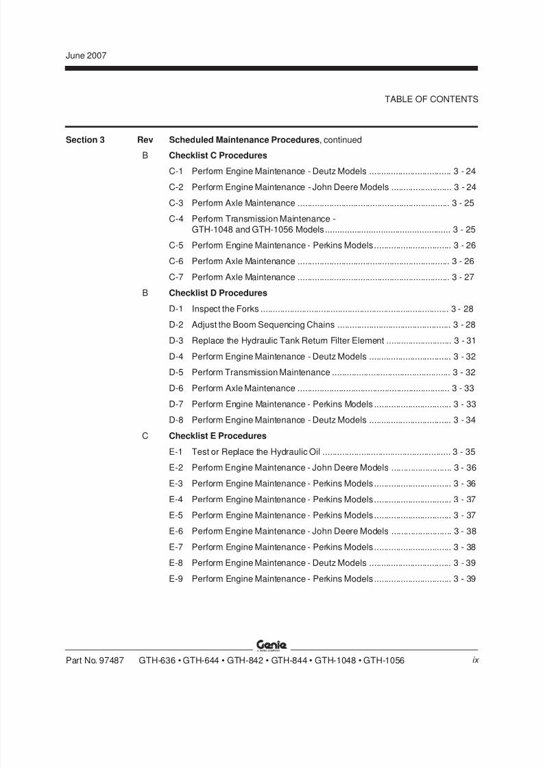
Section 3 Rev Scheduled Maintenance Procedures, continued
B Checklist C Procedures
C-1 Perform Engine Maintenance - Deutz Models .................................. 3 - 24
C-2 Perform Engine Maintenance - John Deere Models ......................... 3 - 24
C-3 Perform Axle Maintenance ............................................................... 3 - 25
C-4 Perform Transmission Maintenance -
GTH-1048 and GTH-1056 Models .................................................... 3 - 25
C-5 Perform Engine Maintenance - Perkins Models................................ 3 - 26
C-6 Perform Axle Maintenance ............................................................... 3 - 26
C-7 Perform Axle Maintenance ............................................................... 3 - 27
B Checklist D Procedures
D-1 Inspect the Forks .............................................................................. 3 - 28
D-2 Adjust the Boom Sequencing Chains ............................................... 3 - 28
D-3 Replace the Hydraulic Tank Return Filter Element ........................... 3 - 31
D-4 Perform Engine Maintenance - Deutz Models .................................. 3 - 32
D-5 Perform Transmission Maintenance ................................................. 3 - 32
D-6 Perform Axle Maintenance ............................................................... 3 - 33
D-7 Perform Engine Maintenance - Perkins Models ................................ 3 - 33
D-8 Perform Engine Maintenance - Deutz Models .................................. 3 - 34
C Checklist E Procedures
E-1 Test or Replace the Hydraulic Oil ..................................................... 3 - 35
E-2 Perform Engine Maintenance - John Deere Models ......................... 3 - 36
E-3 Perform Engine Maintenance - Perkins Models................................ 3 - 36
E-4 Perform Engine Maintenance - Perkins Models................................ 3 - 37
E-5 Perform Engine Maintenance - Perkins Models................................ 3 - 37
E-6 Perform Engine Maintenance - John Deere Models ......................... 3 - 38
E-7 Perform Engine Maintenance - Perkins Models................................ 3 - 38
E-8 Perform Engine Maintenance - Deutz Models .................................. 3 - 39
E-9 Perform Engine Maintenance - Perkins Models................................ 3 - 39
8/14/2019 Genie Manual de Servicio Gth-844
http://slidepdf.com/reader/full/genie-manual-de-servicio-gth-844 10/196
June 2007
GTH-636 • GTH-644 • GTH-842 • GTH-844 • GTH-1048 • GTH-1056 Part No. 97487
TABLE OF CONTENTS
x
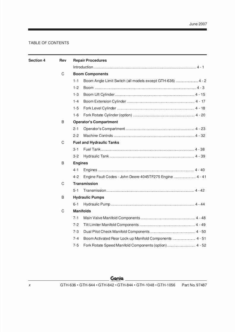
Section 4 Rev Repair Procedures
Introduction .................................................................................................. 4 - 1
C Boom Components
1-1 Boom Angle Limit Switch (all models except GTH-636) ..................... 4 - 2
1-2 Boom ................................................................................................. 4 - 3
1-3 Boom Lift Cylinder............................................................................ 4 - 15
1-4 Boom Extension Cylinder ................................................................. 4 - 17
1-5 Fork Level Cylinder .......................................................................... 4 - 18
1-6 Fork Rotate Cylinder (option) ........................................................... 4 - 20B Operator's Compartment
2-1 Operator's Compartment .................................................................. 4 - 23
2-2 Machine Controls ............................................................................. 4 - 32
C Fuel and Hydraulic Tanks
3-1 Fuel Tank ......................................................................................... 4 - 38
3-2 Hydraulic Tank ................................................................................. 4 - 39
B Engines
4-1 Engines ............................................................................................ 4 - 40
4-2 Engine Fault Codes - John Deere 4045TF275 Engine ..................... 4 - 41
C Transmission
5-1 Transmission.................................................................................... 4 - 42
B Hydraulic Pumps
6-1 Hydraulic Pump ................................................................................ 4 - 44
C Manifolds
7-1 Main Valve Manifold Components .................................................... 4 - 48
7-2 Tilt Limiter Manifold Components ..................................................... 4 - 49
7-3 Dual Pilot Check Manifold Components ........................................... 4 - 507-4 Boom Activated Rear Lock-up Manifold Components ...................... 4 - 51
7-5 Fork Rotate Speed Manifold Components (option)........................... 4 - 52

8/14/2019 Genie Manual de Servicio Gth-844
http://slidepdf.com/reader/full/genie-manual-de-servicio-gth-844 11/196
June 2007
Part No. 97487 GTH-636 • GTH-644 • GTH-842 • GTH-844 • GTH-1048 • GTH-1056
TABLE OF CONTENTS
xi
Section 4 Rev Repair Procedures, continued
7-6 Control Block Manifold Components ................................................ 4 - 53
7-7 Fork Tilt Manifolds Components....................................................... 4 - 54
7-8 Rear Lock-up Manifold Components ................................................ 4 - 55
7-9 Parking Brake Manifold Components ............................................... 4 - 56
7-10 Differential Lock-up Manifold Components
(optional on GTH-636 and GTH-644) ............................................... 4 - 57
7-11 Sway Manifold Components............................................................. 4 - 58
7-12 Fork Rotate Manifold Components (option) ...................................... 4 - 59
7-13 Sway Directional Manifold Components ........................................... 4 - 60
7-14 Outrigger Manifold Components -
GTH-1048 and GTH-1056 ................................................................ 4 - 61
7-15 Controller Relief (Drop Block) Manifold -
GTH-636, GTH-1048 and GTH-1056 ............................................... 4 - 62
7-16 Boom Lift and Boom Extension Cylinders Manifold Components ..... 4 - 63
7-17 Fork Level Cylinder Manifold Components ....................................... 4 - 64
7-18 Fork Rotate Cylinder Manifold Components (option) ........................ 4 - 65
7-19 Pump Destroke Manifold Components ............................................. 4 - 66
7-20 Extend Cylinder Relief Valve Manifold -GTH-636, GTH-1048 and GTH-1056 ............................................... 4 - 67
7-21 Boom Activated Sway Lock-up Manifold Components ..................... 4 - 68
7-22 Valve Adjustments - Control Block Manifold ..................................... 4 - 69
7-23 Valve Adjustments - Tilt Limiter Manifold.......................................... 4 - 71
7-24 Valve Coils ....................................................................................... 4 - 72
D Axle Components
8-1 Axles ................................................................................................ 4 - 73
A Outriggers
9-1 Outriggers ........................................................................................ 4 - 76
8/14/2019 Genie Manual de Servicio Gth-844
http://slidepdf.com/reader/full/genie-manual-de-servicio-gth-844 12/196
June 2007
GTH-636 • GTH-644 • GTH-842 • GTH-844 • GTH-1048 • GTH-1056 Part No. 97487xii
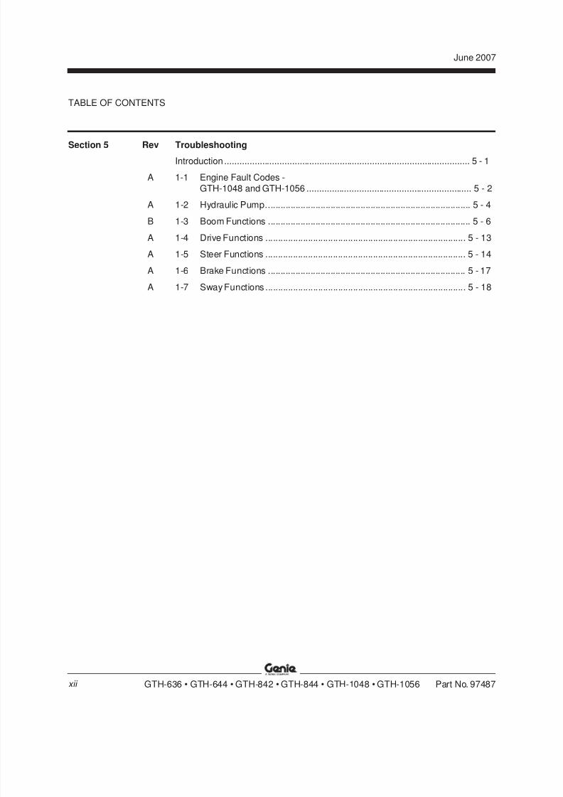
Section 5 Rev Troubleshooting
Introduction .................................................................................................. 5 - 1
A 1-1 Engine Fault Codes -
GTH-1048 and GTH-1056 .................................................................. 5 - 2
A 1-2 Hydraulic Pump.................................................................................. 5 - 4
B 1-3 Boom Functions ................................................................................. 5 - 6
A 1-4 Drive Functions ................................................................................ 5 - 13
A 1-5 Steer Functions ................................................................................ 5 - 14
A 1-6 Brake Functions ............................................................................... 5 - 17
A 1-7 Sway Functions ................................................................................ 5 - 18
TABLE OF CONTENTS
8/14/2019 Genie Manual de Servicio Gth-844
http://slidepdf.com/reader/full/genie-manual-de-servicio-gth-844 13/196
June 2007
Part No. 97487 GTH-636 • GTH-644 • GTH-842 • GTH-844 • GTH-1048 • GTH-1056
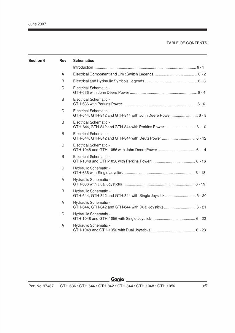
Section 6 Rev Schematics
Introduction .................................................................................................. 6 - 1
A Electrical Component and Limit Switch Legends ......................................... 6 - 2
B Electrical and Hydraulic Symbols Legends .................................................. 6 - 3
C Electrical Schematic -GTH-636 with John Deere Power ................................................................ 6 - 4
B Electrical Schematic -GTH-636 with Perkins Power ....................................................................... 6 - 6
C Electrical Schematic -
GTH-644, GTH-842 and GTH-844 with John Deere Power ......................... 6 - 8B Electrical Schematic -
GTH-644, GTH-842 and GTH-844 with Perkins Power ............................. 6 - 10
B Electrical Schematic -GTH-644, GTH-842 and GTH-844 with Deutz Power ................................ 6 - 12
C Electrical Schematic -GTH-1048 and GTH-1056 with John Deere Power .................................... 6 - 14
B Electrical Schematic -GTH-1048 and GTH-1056 with Perkins Power .......................................... 6 - 16
C Hydraulic Schematic -GTH-636 with Single Joystick .................................................................... 6 - 18
A Hydraulic Schematic -
GTH-636 with Dual Joysticks ..................................................................... 6 - 19
B Hydraulic Schematic -
GTH-644, GTH-842 and GTH-844 with Single Joystick ............................. 6 - 20
A Hydraulic Schematic -
GTH-644, GTH-842 and GTH-844 with Dual Joysticks .............................. 6 - 21
C Hydraulic Schematic -
GTH-1048 and GTH-1056 with Single Joystick.......................................... 6 - 22
A Hydraulic Schematic -
GTH-1048 and GTH-1056 with Dual Joysticks .......................................... 6 - 23
TABLE OF CONTENTS
xiii

8/14/2019 Genie Manual de Servicio Gth-844
http://slidepdf.com/reader/full/genie-manual-de-servicio-gth-844 14/196
June 2007
GTH-636 • GTH-644 • GTH-842 • GTH-844 • GTH-1048 • GTH-1056 Part No. 97487xiv
This page intentionally left blank.

8/14/2019 Genie Manual de Servicio Gth-844
http://slidepdf.com/reader/full/genie-manual-de-servicio-gth-844 15/196
REV D
Section 2 SpecificationsJune 2007
Part No. 97487 GTH-636 • GTH-644 • GTH-842 • GTH-844 • GTH-1048 • GTH-1056 2 - 1
Specifications
Machine SpecificationsFluid capacities
GTH-636, GTH-644, GTH-842 and GTH 844
Fuel tank 30 gallons
113.6 liters
Hydraulic tank 34 gallons
128.7 liters
Hydraulic system 50 gallons
(including tank) 189.3 liters
For operational specifications, refer to the
Operator's Manual.
GTH-1048 and GTH-1056
Fuel tank 30 gallons
113.6 liters
Hydraulic tank 48 gallons
181.7 liters
Hydraulic system 66 gallons
(including tank) 249.8 liters
Continuous improvement of our products is a
Genie policy. Product specifications are
subject to change without notice.
8/14/2019 Genie Manual de Servicio Gth-844
http://slidepdf.com/reader/full/genie-manual-de-servicio-gth-844 16/196
REV D
Section 2 • Specifications June 2007
2 - 2 GTH-636 • GTH-644 • GTH-842 • GTH-844 • GTH-1048 • GTH-1056 Part No. 97487
SPECIFICATIONS
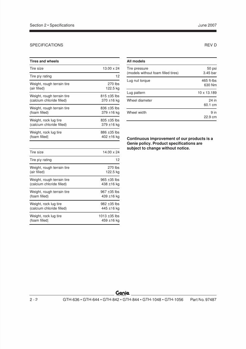
Tires and wheels
Tire size 13.00 x 24
Tire ply rating 12
Weight, rough terrain tire 270 lbs
(air filled) 122.5 kg
Weight, rough terrain tire 815 ±35 lbs
(calcium chloride filled) 370 ±16 kg
Weight, rough terrain tire 836 ±35 lbs
(foam filled) 379 ±16 kg
Weight, rock lug tire 835 ±35 lbs
(calcium chloride filled) 379 ±16 kg
Weight, rock lug tire 886 ±35 lbs
(foam filled) 402 ±16 kg
Tire size 14.00 x 24
Tire ply rating 12
Weight, rough terrain tire 270 lbs
(air filled) 122.5 kg
Weight, rough terrain tire 965 ±35 lbs
(calcium chloride filled) 438 ±16 kg
Weight, rough terrain tire 967 ±35 lbs
(foam filled) 439 ±16 kg
Weight, rock lug tire 982 ±35 lbs
(calcium chloride filled) 445 ±16 kg
Weight, rock lug tire 1013 ±35 lbs
(foam filled) 459 ±16 kg
All models
Tire pressure 50 psi
(models without foam filled tires) 3.45 bar
Lug nut torque 465 ft-lbs
630 Nm
Lug pattern 10 x 13.189
Wheel diameter 24 in
60.1 cm
Wheel width 9 in
22.9 cm
Continuous improvement of our products is aGenie policy. Product specifications aresubject to change without notice.
8/14/2019 Genie Manual de Servicio Gth-844
http://slidepdf.com/reader/full/genie-manual-de-servicio-gth-844 17/196
REV D
Section 2 • SpecificationsJune 2007
Part No. 97487 GTH-636 • GTH-644 • GTH-842 • GTH-844 • GTH-1048 • GTH-1056 2 - 3
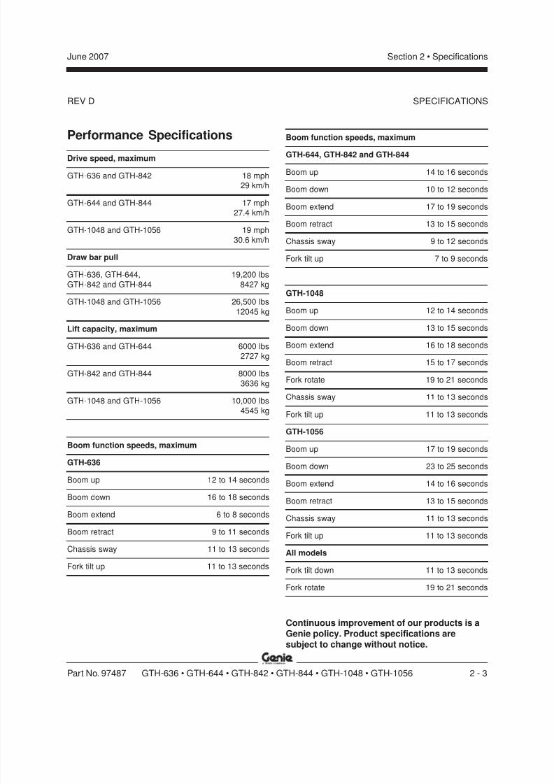
Performance SpecificationsDrive speed, maximum
GTH-636 and GTH-842 18 mph
29 km/h
GTH-644 and GTH-844 17 mph
27.4 km/h
GTH-1048 and GTH-1056 19 mph
30.6 km/h
Draw bar pull
GTH-636, GTH-644, 19,200 lbsGTH-842 and GTH-844 8427 kg
GTH-1048 and GTH-1056 26,500 lbs
12045 kg
Lift capacity, maximum
GTH-636 and GTH-644 6000 lbs
2727 kg
GTH-842 and GTH-844 8000 lbs
3636 kg
GTH-1048 and GTH-1056 10,000 lbs
4545 kg
Boom function speeds, maximum
GTH-636
Boom up 12 to 14 seconds
Boom down 16 to 18 seconds
Boom extend 6 to 8 seconds
Boom retract 9 to 11 seconds
Chassis sway 11 to 13 seconds
Fork tilt up 11 to 13 seconds
SPECIFICATIONS
Boom function speeds, maximum
GTH-644, GTH-842 and GTH-844
Boom up 14 to 16 seconds
Boom down 10 to 12 seconds
Boom extend 17 to 19 seconds
Boom retract 13 to 15 seconds
Chassis sway 9 to 12 seconds
Fork tilt up 7 to 9 seconds
GTH-1048
Boom up 12 to 14 seconds
Boom down 13 to 15 seconds
Boom extend 16 to 18 seconds
Boom retract 15 to 17 seconds
Fork rotate 19 to 21 seconds
Chassis sway 11 to 13 seconds
Fork tilt up 11 to 13 seconds
GTH-1056
Boom up 17 to 19 seconds
Boom down 23 to 25 seconds
Boom extend 14 to 16 seconds
Boom retract 13 to 15 seconds
Chassis sway 11 to 13 seconds
Fork tilt up 11 to 13 seconds
All models
Fork tilt down 11 to 13 seconds
Fork rotate 19 to 21 seconds
Continuous improvement of our products is aGenie policy. Product specifications aresubject to change without notice.
8/14/2019 Genie Manual de Servicio Gth-844
http://slidepdf.com/reader/full/genie-manual-de-servicio-gth-844 18/196
REV D
Section 2 • Specifications June 2007
2 - 4 GTH-636 • GTH-644 • GTH-842 • GTH-844 • GTH-1048 • GTH-1056 Part No. 97487
SPECIFICATIONS
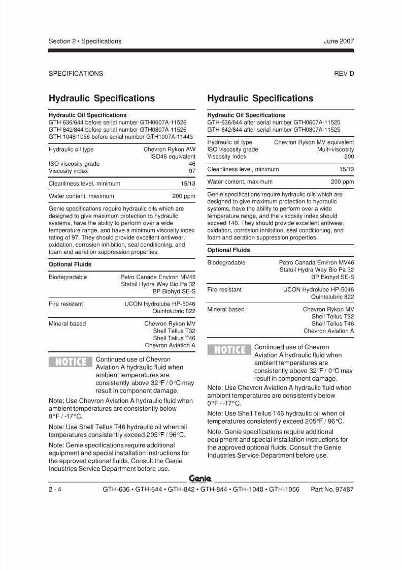
Hydraulic SpecificationsHydraulic Oil Specifications
GTH-636/644 before serial number GTH0607A-11526
GTH-842/844 before serial number GTH0807A-11526
GTH-1048/1056 before serial number GTH1007A-11443
Hydraulic oil type Chevron Rykon AW
ISO46 equivalent
ISO viscosity grade 46
Viscosity index 97
Cleanliness level, minimum 15/13
Water content, maximum 200 ppm
Genie specifications require hydraulic oils which are
designed to give maximum protection to hydraulic
systems, have the ability to perform over a wide
temperature range, and have a minimum viscosity index
rating of 97. They should provide excellent antiwear,
oxidation, corrosion inhibition, seal conditioning, and
foam and aeration suppression properties.
Optional Fluids
Biodegradable Petro Canada Environ MV46
Statoil Hydra Way Bio Pa 32
BP Biohyd SE-S
Fire resistant UCON Hydrolube HP-5046
Quintolubric 822
Mineral based Chevron Rykon MV
Shell Tellus T32
Shell Tellus T46
Chevron Aviation A
Continued use of ChevronAviation A hydraulic fluid whenambient temperatures are
consistently above 32°F / 0°C mayresult in component damage.
Note: Use Chevron Aviation A hydraulic fluid whenambient temperatures are consistently below0°F / -17°C.
Note: Use Shell Tellus T46 hydraulic oil when oiltemperatures consistently exceed 205°F / 96°C.
Note: Genie specifications require additionalequipment and special installation instructions for
the approved optional fluids. Consult the GenieIndustries Service Department before use.
Hydraulic SpecificationsHydraulic Oil Specifications
GTH-636/644 after serial number GTH0607A-11525
GTH-842/844 after serial number GTH0807A-11525
Hydraulic oil type Chevron Rykon MV equivalent
ISO viscosity grade Multi-viscosity
Viscosity index 200
Cleanliness level, minimum 15/13
Water content, maximum 200 ppm
Genie specifications require hydraulic oils which are
designed to give maximum protection to hydraulicsystems, have the ability to perform over a wide
temperature range, and the viscosity index should
exceed 140. They should provide excellent antiwear,
oxidation, corrosion inhibition, seal conditioning, and
foam and aeration suppression properties.
Optional Fluids
Biodegradable Petro Canada Environ MV46
Statoil Hydra Way Bio Pa 32
BP Biohyd SE-S
Fire resistant UCON Hydrolube HP-5046
Quintolubric 822
Mineral based Chevron Rykon MV
Shell Tellus T32
Shell Tellus T46
Chevron Aviation A
Continued use of Chevron
Aviation A hydraulic fluid whenambient temperatures are
consistently above 32°F / 0°C mayresult in component damage.
Note: Use Chevron Aviation A hydraulic fluid whenambient temperatures are consistently below
0°F / -17°C.
Note: Use Shell Tellus T46 hydraulic oil when oiltemperatures consistently exceed 205°F / 96°C.
Note: Genie specifications require additionalequipment and special installation instructions for
the approved optional fluids. Consult the GenieIndustries Service Department before use.
8/14/2019 Genie Manual de Servicio Gth-844
http://slidepdf.com/reader/full/genie-manual-de-servicio-gth-844 19/196
REV D
Section 2 • SpecificationsJune 2007
Part No. 97487 GTH-636 • GTH-644 • GTH-842 • GTH-844 • GTH-1048 • GTH-1056 2 - 5
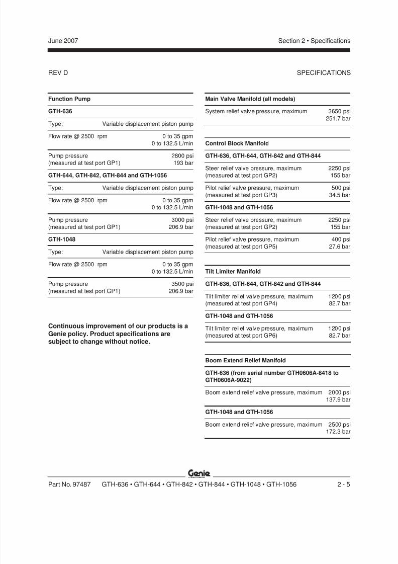
Function Pump
GTH-636
Type: Variable displacement piston pump
Flow rate @ 2500 rpm 0 to 35 gpm
0 to 132.5 L/min
Pump pressure 2800 psi
(measured at test port GP1) 193 bar
GTH-644, GTH-842, GTH-844 and GTH-1056
Type: Variable displacement piston pump
Flow rate @ 2500 rpm 0 to 35 gpm
0 to 132.5 L/min
Pump pressure 3000 psi
(measured at test port GP1) 206.9 bar
GTH-1048
Type: Variable displacement piston pump
Flow rate @ 2500 rpm 0 to 35 gpm
0 to 132.5 L/min
Pump pressure 3500 psi
(measured at test port GP1) 206.9 bar
Continuous improvement of our products is a
Genie policy. Product specifications aresubject to change without notice.
Main Valve Manifold (all models)
System relief valve pressure, maximum 3650 psi
251.7 bar
Control Block Manifold
GTH-636, GTH-644, GTH-842 and GTH-844
Steer relief valve pressure, maximum 2250 psi
(measured at test port GP2) 155 bar
Pilot relief valve pressure, maximum 500 psi
(measured at test port GP3) 34.5 bar
GTH-1048 and GTH-1056
Steer relief valve pressure, maximum 2250 psi
(measured at test port GP2) 155 bar
Pilot relief valve pressure, maximum 400 psi
(measured at test port GP5) 27.6 bar
Tilt Limiter Manifold
GTH-636, GTH-644, GTH-842 and GTH-844
Tilt limiter relief valve pressure, maximum 1200 psi(measured at test port GP4) 82.7 bar
GTH-1048 and GTH-1056
Tilt limiter relief valve pressure, maximum 1200 psi
(measured at test port GP6) 82.7 bar
Boom Extend Relief Manifold
GTH-636 (from serial number GTH0606A-8418 to
GTH0606A-9022)
Boom extend relief valve pressure, maximum 2000 psi137.9 bar
GTH-1048 and GTH-1056
Boom extend relief valve pressure, maximum 2500 psi
172.3 bar
SPECIFICATIONS
8/14/2019 Genie Manual de Servicio Gth-844
http://slidepdf.com/reader/full/genie-manual-de-servicio-gth-844 20/196
REV D
Section 2 • Specifications June 2007
2 - 6 GTH-636 • GTH-644 • GTH-842 • GTH-844 • GTH-1048 • GTH-1056 Part No. 97487
SPECIFICATIONS
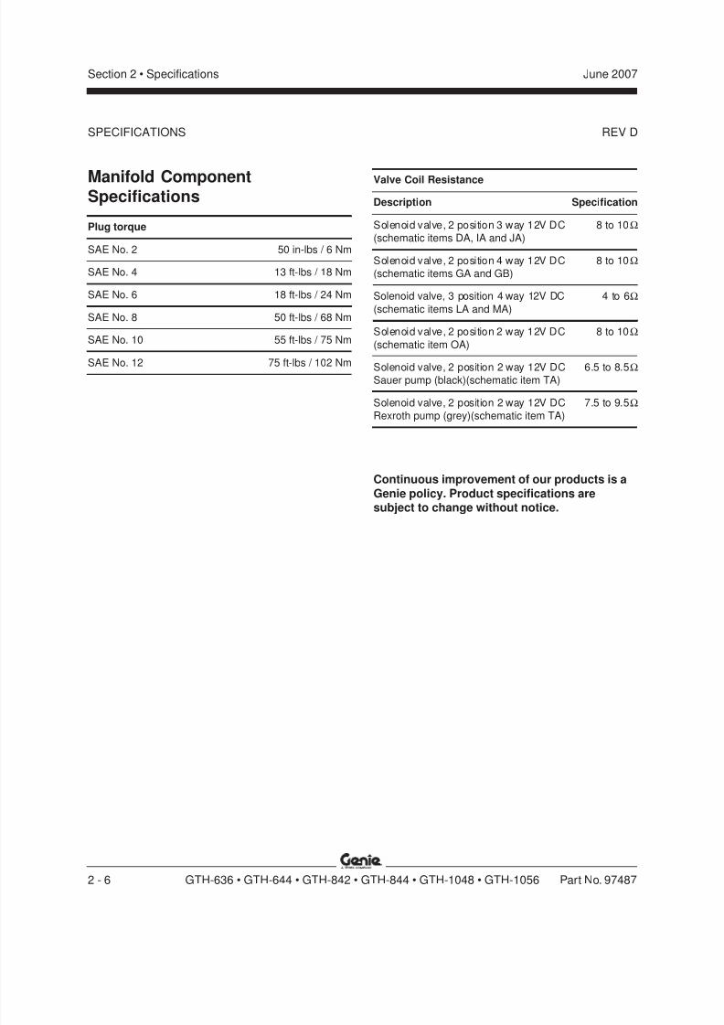
Manifold ComponentSpecifications
Plug torque
SAE No. 2 50 in-lbs / 6 Nm
SAE No. 4 13 ft-lbs / 18 Nm
SAE No. 6 18 ft-lbs / 24 Nm
SAE No. 8 50 ft-lbs / 68 Nm
SAE No. 10 55 ft-lbs / 75 Nm
SAE No. 12 75 ft-lbs / 102 Nm
Valve Coil Resistance
Description Specification
Solenoid valve, 2 position 3 way 12V DC 8 to 10Ω
(schematic items DA, IA and JA)
Solenoid valve, 2 position 4 way 12V DC 8 to 10Ω
(schematic items GA and GB)
Solenoid valve, 3 position 4 way 12V DC 4 to 6Ω
(schematic items LA and MA)
Solenoid valve, 2 position 2 way 12V DC 8 to 10Ω
(schematic item OA)
Solenoid valve, 2 position 2 way 12V DC 6.5 to 8.5Ω
Sauer pump (black)(schematic item TA)
Solenoid valve, 2 position 2 way 12V DC 7.5 to 9.5Ω
Rexroth pump (grey)(schematic item TA)
Continuous improvement of our products is a
Genie policy. Product specifications aresubject to change without notice.
8/14/2019 Genie Manual de Servicio Gth-844
http://slidepdf.com/reader/full/genie-manual-de-servicio-gth-844 21/196
REV D
Section 2 • SpecificationsJune 2007
Part No. 97487 GTH-636 • GTH-644 • GTH-842 • GTH-844 • GTH-1048 • GTH-1056 2 - 7
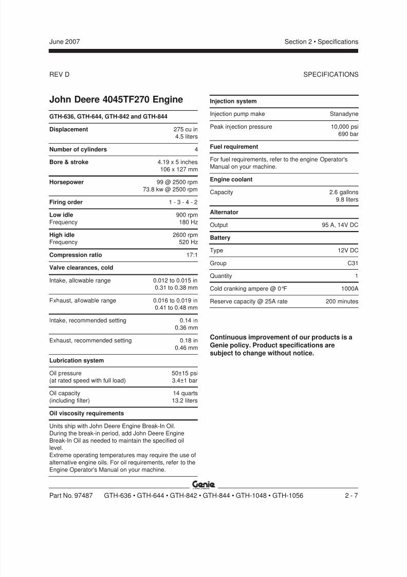
John Deere 4045TF270 EngineGTH-636, GTH-644, GTH-842 and GTH-844
Displacement 275 cu in
4.5 liters
Number of cylinders 4
Bore & stroke 4.19 x 5 inches
106 x 127 mm
Horsepower 99 @ 2500 rpm
73.8 kw @ 2500 rpm
Firing order 1 - 3 - 4 - 2
Low idle 900 rpm
Frequency 180 Hz
High idle 2600 rpm
Frequency 520 Hz
Compression ratio 17:1
Valve clearances, cold
Intake, allowable range 0.012 to 0.015 in
0.31 to 0.38 mm
Exhaust, allowable range 0.016 to 0.019 in0.41 to 0.48 mm
Intake, recommended setting 0.14 in
0.36 mm
Exhaust, recommended setting 0.18 in
0.46 mm
Lubrication system
Oil pressure 50±15 psi
(at rated speed with full load) 3.4±1 bar
Oil capacity 14 quarts
(including filter) 13.2 liters
Oil viscosity requirements
Units ship with John Deere Engine Break-In Oil.
During the break-in period, add John Deere Engine
Break-In Oil as needed to maintain the specified oil
level.
Extreme operating temperatures may require the use of
alternative engine oils. For oil requirements, refer to the
Engine Operator's Manual on your machine.
Injection system
Injection pump make Stanadyne
Peak injection pressure 10,000 psi
690 bar
Fuel requirement
For fuel requirements, refer to the engine Operator's
Manual on your machine.
Engine coolant
Capacity 2.6 gallons
9.8 liters
Alternator
Output 95 A, 14V DC
Battery
Type 12V DC
Group C31
Quantity 1
Cold cranking ampere @ 0°F 1000A
Reserve capacity @ 25A rate 200 minutes
Continuous improvement of our products is a
Genie policy. Product specifications aresubject to change without notice.
SPECIFICATIONS
8/14/2019 Genie Manual de Servicio Gth-844
http://slidepdf.com/reader/full/genie-manual-de-servicio-gth-844 22/196
REV D
Section 2 • Specifications June 2007
2 - 8 GTH-636 • GTH-644 • GTH-842 • GTH-844 • GTH-1048 • GTH-1056 Part No. 97487
SPECIFICATIONS
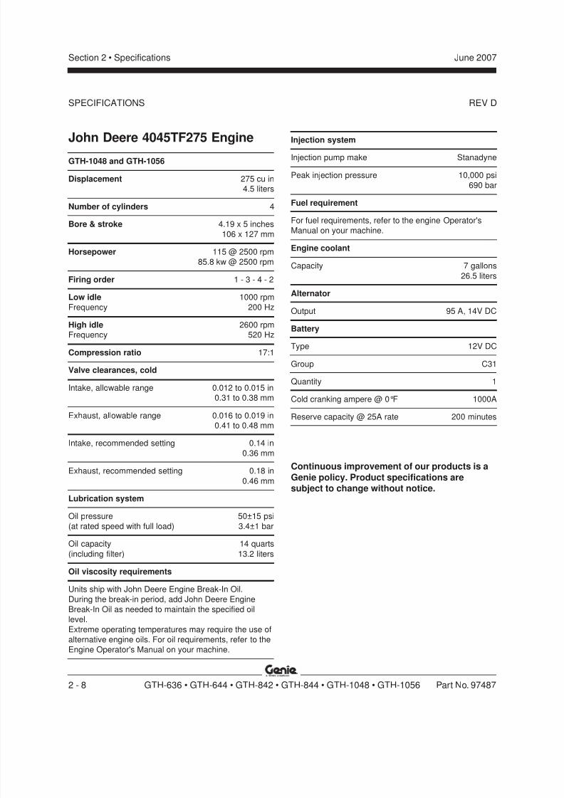
John Deere 4045TF275 EngineGTH-1048 and GTH-1056
Displacement 275 cu in
4.5 liters
Number of cylinders 4
Bore & stroke 4.19 x 5 inches
106 x 127 mm
Horsepower 115 @ 2500 rpm
85.8 kw @ 2500 rpm
Firing order 1 - 3 - 4 - 2
Low idle 1000 rpm
Frequency 200 Hz
High idle 2600 rpm
Frequency 520 Hz
Compression ratio 17:1
Valve clearances, cold
Intake, allowable range 0.012 to 0.015 in
0.31 to 0.38 mm
Exhaust, allowable range 0.016 to 0.019 in0.41 to 0.48 mm
Intake, recommended setting 0.14 in
0.36 mm
Exhaust, recommended setting 0.18 in
0.46 mm
Lubrication system
Oil pressure 50±15 psi
(at rated speed with full load) 3.4±1 bar
Oil capacity 14 quarts
(including filter) 13.2 liters
Oil viscosity requirements
Units ship with John Deere Engine Break-In Oil.
During the break-in period, add John Deere Engine
Break-In Oil as needed to maintain the specified oil
level.
Extreme operating temperatures may require the use of
alternative engine oils. For oil requirements, refer to the
Engine Operator's Manual on your machine.
Injection system
Injection pump make Stanadyne
Peak injection pressure 10,000 psi
690 bar
Fuel requirement
For fuel requirements, refer to the engine Operator's
Manual on your machine.
Engine coolant
Capacity 7 gallons
26.5 liters
Alternator
Output 95 A, 14V DC
Battery
Type 12V DC
Group C31
Quantity 1
Cold cranking ampere @ 0°F 1000A
Reserve capacity @ 25A rate 200 minutes
Continuous improvement of our products is a
Genie policy. Product specifications aresubject to change without notice.
8/14/2019 Genie Manual de Servicio Gth-844
http://slidepdf.com/reader/full/genie-manual-de-servicio-gth-844 23/196
REV D
Section 2 • SpecificationsJune 2007
Part No. 97487 GTH-636 • GTH-644 • GTH-842 • GTH-844 • GTH-1048 • GTH-1056 2 - 9
SPECIFICATIONS
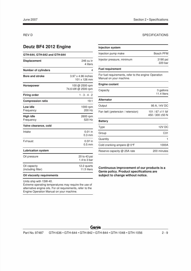
Deutz BF4 2012 EngineGTH-644, GTH-842 and GTH-844
Displacement 246 cu in
4 liters
Number of cylinders 4
Bore and stroke 3.97 x 4.96 inches
101 x 126 mm
Horsepower 100 @ 2500 rpm
74.6 kW @ 2500 rpm
Firing order 1 - 3 - 4 - 2
Compression ratio 19:1
Low idle 1000 rpm
Frequency 200 Hz
High idle 2600 rpm
Frequency 520 Hz
Valve clearance, cold
Intake 0.01 in
0.3 mm
Exhaust 0.02 in0.5 mm
Lubrication system
Oil pressure 20 to 43 psi
1.4 to 3 bar
Oil capacity 12.2 quarts
(including filter) 11.5 liters
Oil viscosity requirements
Units ship with 15W-40.
Extreme operating temperatures may require the use of
alternative engine oils. For oil requirements, refer to the
Engine Operation Manual on your machine.
Injection system
Injection pump make Bosch PFM
Injector pressure, minimum 3190 psi
220 bar
Fuel requirement
For fuel requirements, refer to the engine Operation
Manual on your machine.
Engine coolant
Capacity 3 gallons
11.4 liters
Alternator
Output 95 A, 14V DC
Fan belt (pretension / retension) 101 / 67 ±11 lbf
450 / 300 ±50 N
Battery
Type 12V DC
Group C31
Quantity 1
Cold cranking ampere @ 0°F 1000A
Reserve capacity @ 25A rate 200 minutes
Continuous improvement of our products is aGenie policy. Product specifications are
subject to change without notice.
8/14/2019 Genie Manual de Servicio Gth-844
http://slidepdf.com/reader/full/genie-manual-de-servicio-gth-844 24/196
REV D
Section 2 • Specifications June 2007
2 - 10 GTH-636 • GTH-644 • GTH-842 • GTH-844 • GTH-1048 • GTH-1056 Part No. 97487
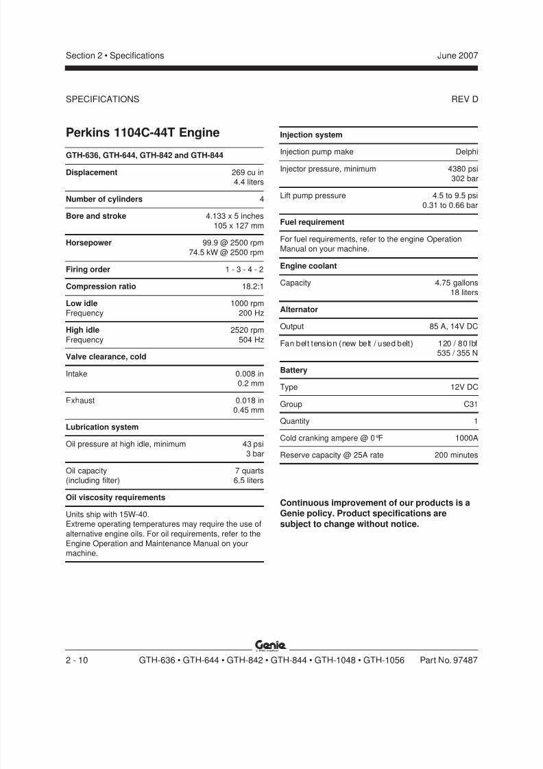
Perkins 1104C-44T EngineGTH-636, GTH-644, GTH-842 and GTH-844
Displacement 269 cu in
4.4 liters
Number of cylinders 4
Bore and stroke 4.133 x 5 inches
105 x 127 mm
Horsepower 99.9 @ 2500 rpm
74.5 kW @ 2500 rpm
Firing order 1 - 3 - 4 - 2
Compression ratio 18.2:1
Low idle 1000 rpm
Frequency 200 Hz
High idle 2520 rpm
Frequency 504 Hz
Valve clearance, cold
Intake 0.008 in
0.2 mm
Exhaust 0.018 in0.45 mm
Lubrication system
Oil pressure at high idle, minimum 43 psi
3 bar
Oil capacity 7 quarts
(including filter) 6.5 liters
Oil viscosity requirements
Units ship with 15W-40.
Extreme operating temperatures may require the use of
alternative engine oils. For oil requirements, refer to the
Engine Operation and Maintenance Manual on your
machine.
Injection system
Injection pump make Delphi
Injector pressure, minimum 4380 psi
302 bar
Lift pump pressure 4.5 to 9.5 psi
0.31 to 0.66 bar
Fuel requirement
For fuel requirements, refer to the engine Operation
Manual on your machine.
Engine coolant
Capacity 4.75 gallons
18 liters
Alternator
Output 85 A, 14V DC
Fan belt tension (new belt / used belt) 120 / 80 lbf
535 / 355 N
Battery
Type 12V DC
Group C31
Quantity 1
Cold cranking ampere @ 0°F 1000A
Reserve capacity @ 25A rate 200 minutes
Continuous improvement of our products is aGenie policy. Product specifications are
subject to change without notice.
SPECIFICATIONS

8/14/2019 Genie Manual de Servicio Gth-844
http://slidepdf.com/reader/full/genie-manual-de-servicio-gth-844 25/196
REV D
Section 2 • SpecificationsJune 2007
Part No. 97487 GTH-636 • GTH-644 • GTH-842 • GTH-844 • GTH-1048 • GTH-1056 2 - 11
Perkins 1104C-44TA EngineGTH-1048 and GTH-1056
Displacement 269 cu in
4.4 liters
Number of cylinders 4
Bore and stroke 4.133 x 5 inches
105 x 127 mm
Horsepower 127 @ 2200 rpm
94.7 kW @ 2200 rpm
Firing order 1 - 3 - 4 - 2
Compression ratio 18.2:1
Low idle 1000 rpm
Frequency 200 Hz
High idle 2310 rpm
Frequency 462 Hz
Valve clearance, cold
Intake 0.008 in
0.2 mm
Exhaust 0.018 in0.45 mm
Lubrication system
Oil pressure at high idle, minimum 43 psi
3 bar
Oil capacity 8.3 quarts
(including filter) 7.85 liters
Oil viscosity requirements
Units ship with 15W-40.
Extreme operating temperatures may require the use of
alternative engine oils. For oil requirements, refer to the
Engine Operation and Maintenance Manual on your
machine.
Injection system
Injection pump make Delphi
Injector pressure, minimum 4380 psi
302 bar
Lift pump pressure 4.5 to 9.5 psi
0.31 to 0.66 bar
Fuel requirement
For fuel requirements, refer to the engine Operation
Manual on your machine.
Engine coolant
Capacity 5 gallons
18.9 liters
Alternator
Output 85 A, 14V DC
Fan belt tension (new belt / used belt) 120 / 80 lbf
535 / 355 N
Battery
Type 12V DC
Group C31
Quantity 1
Cold cranking ampere @ 0°F 1000A
Reserve capacity @ 25A rate 200 minutes
Continuous improvement of our products is aGenie policy. Product specifications are
subject to change without notice.
SPECIFICATIONS
8/14/2019 Genie Manual de Servicio Gth-844
http://slidepdf.com/reader/full/genie-manual-de-servicio-gth-844 26/196
REV D
Section 2 • Specifications June 2007
2 - 12 GTH-636 • GTH-644 • GTH-842 • GTH-844 • GTH-1048 • GTH-1056 Part No. 97487
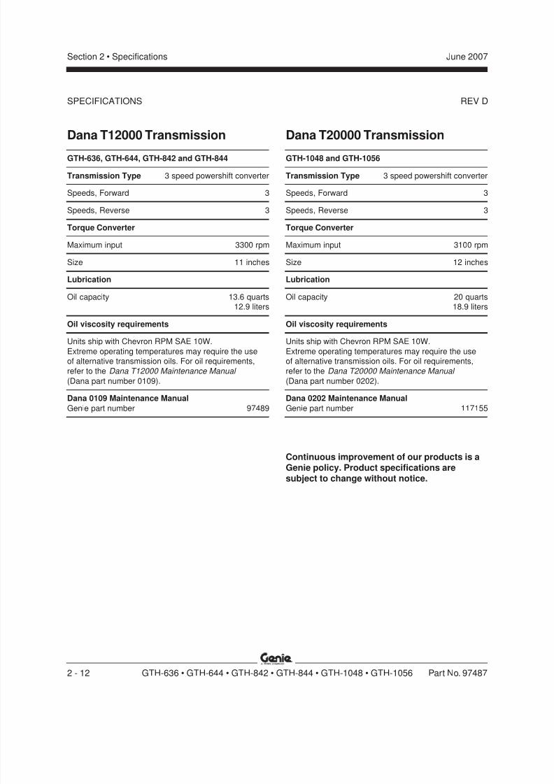
Dana T12000 TransmissionGTH-636, GTH-644, GTH-842 and GTH-844
Transmission Type 3 speed powershift converter
Speeds, Forward 3
Speeds, Reverse 3
Torque Converter
Maximum input 3300 rpm
Size 11 inches
Lubrication
Oil capacity 13.6 quarts
12.9 liters
Oil viscosity requirements
Units ship with Chevron RPM SAE 10W.
Extreme operating temperatures may require the use
of alternative transmission oils. For oil requirements,
refer to the Dana T12000 Maintenance Manual
(Dana part number 0109).
Dana 0109 Maintenance Manual
Genie part number 97489
Dana T20000 TransmissionGTH-1048 and GTH-1056
Transmission Type 3 speed powershift converter
Speeds, Forward 3
Speeds, Reverse 3
Torque Converter
Maximum input 3100 rpm
Size 12 inches
Lubrication
Oil capacity 20 quarts
18.9 liters
Oil viscosity requirements
Units ship with Chevron RPM SAE 10W.
Extreme operating temperatures may require the use
of alternative transmission oils. For oil requirements,
refer to the Dana T20000 Maintenance Manual
(Dana part number 0202).
Dana 0202 Maintenance Manual
Genie part number 117155
Continuous improvement of our products is aGenie policy. Product specifications aresubject to change without notice.
SPECIFICATIONS
8/14/2019 Genie Manual de Servicio Gth-844
http://slidepdf.com/reader/full/genie-manual-de-servicio-gth-844 27/196
REV D
Section 2 • SpecificationsJune 2007
Part No. 97487 GTH-636 • GTH-644 • GTH-842 • GTH-844 • GTH-1048 • GTH-1056 2 - 13
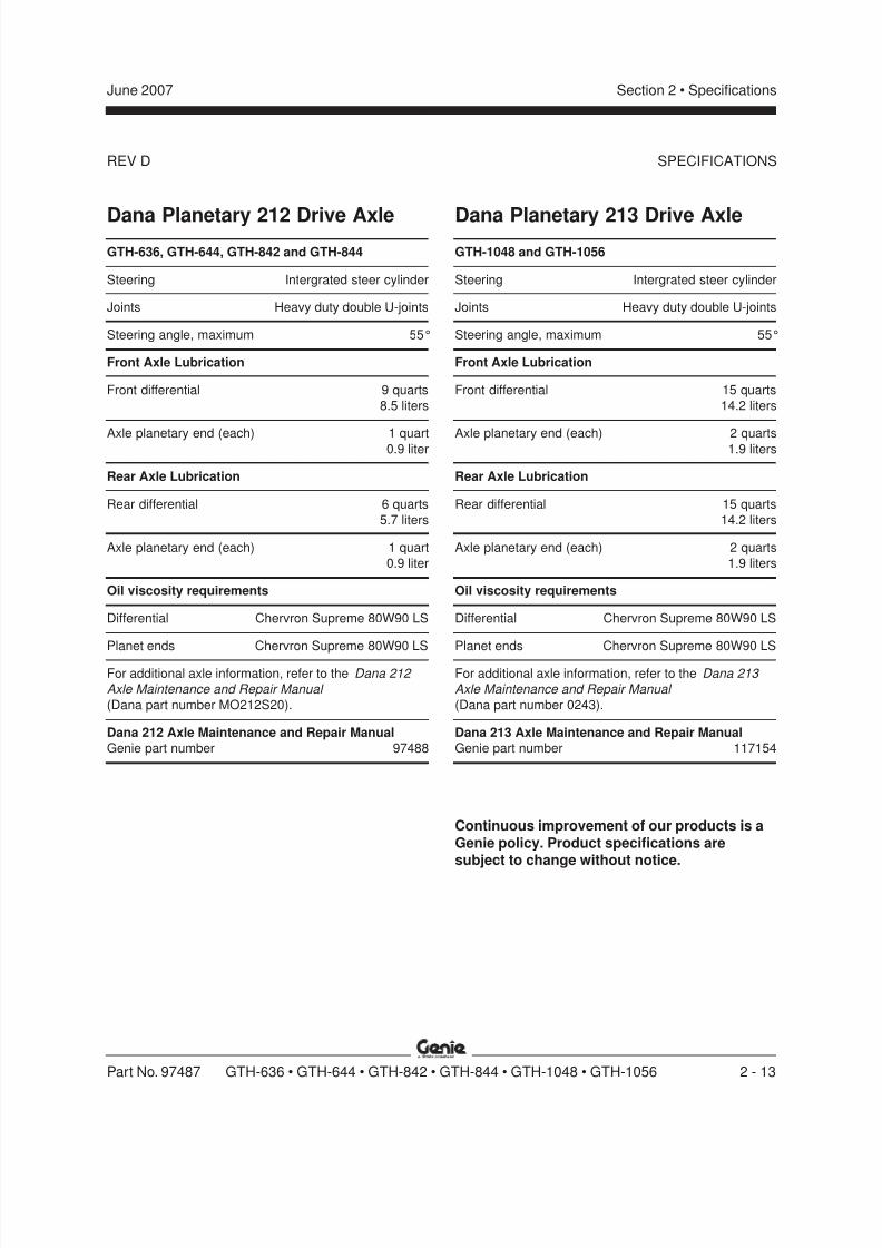
Dana Planetary 212 Drive AxleGTH-636, GTH-644, GTH-842 and GTH-844
Steering Intergrated steer cylinder
Joints Heavy duty double U-joints
Steering angle, maximum 55°
Front Axle Lubrication
Front differential 9 quarts
8.5 liters
Axle planetary end (each) 1 quart0.9 liter
Rear Axle Lubrication
Rear differential 6 quarts
5.7 liters
Axle planetary end (each) 1 quart
0.9 liter
Oil viscosity requirements
Differential Chervron Supreme 80W90 LS
Planet ends Chervron Supreme 80W90 LS
For additional axle information, refer to the Dana 212
Axle Maintenance and Repair Manual
(Dana part number MO212S20).
Dana 212 Axle Maintenance and Repair Manual
Genie part number 97488
SPECIFICATIONS
Dana Planetary 213 Drive AxleGTH-1048 and GTH-1056
Steering Intergrated steer cylinder
Joints Heavy duty double U-joints
Steering angle, maximum 55°
Front Axle Lubrication
Front differential 15 quarts
14.2 liters
Axle planetary end (each) 2 quarts1.9 liters
Rear Axle Lubrication
Rear differential 15 quarts
14.2 liters
Axle planetary end (each) 2 quarts
1.9 liters
Oil viscosity requirements
Differential Chervron Supreme 80W90 LS
Planet ends Chervron Supreme 80W90 LS
For additional axle information, refer to the Dana 213
Axle Maintenance and Repair Manual
(Dana part number 0243).
Dana 213 Axle Maintenance and Repair Manual
Genie part number 117154
Continuous improvement of our products is a
Genie policy. Product specifications aresubject to change without notice.
8/14/2019 Genie Manual de Servicio Gth-844
http://slidepdf.com/reader/full/genie-manual-de-servicio-gth-844 28/196
REV D
Section 2 • Specifications June 2007
2 - 14 GTH-636 • GTH-644 • GTH-842 • GTH-844 • GTH-1048 • GTH-1056 Part No. 97487
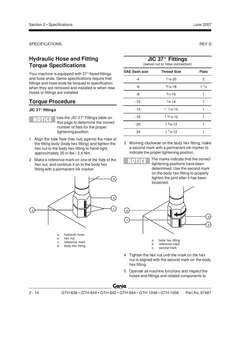
Hydraulic Hose and FittingTorque Specifications
Your machine is equipped with 37° flared fittingsand hose ends. Genie specifications require thatfittings and hose ends be torqued to specification
when they are removed and installed or when newhoses or fittings are installed.
JIC 37° Fittings(swivel nut or hose connection)
SAE Dash size Thread Size Flats
-4 7 / 16-20 2
-6 9 / 16-18 1 1 / 4
-8 3 / 4-16 1
-10 7 / 8-14 1
-12 1 1 / 16-12 1
-16 1 5 / 16-12 1
-20 1 5 / 8-12 1
-24 1 7 / 8-12 1
Torque Procedure
JIC 37° fittings
Use the JIC 37° Fittings table onthis page to determine the correctnumber of flats for the proper
tightening position.
1 Align the tube flare (hex nut) against the nose ofthe fitting body (body hex fitting) and tighten the
hex nut to the body hex fitting to hand-tight,approximately 30 in-lbs / 3.4 Nm.
2 Make a reference mark on one of the flats of thehex nut, and continue it on to the body hexfitting with a permanent ink marker.
3 Working clockwise on the body hex fitting, makea second mark with a permanent ink marker to
indicate the proper tightening position.
The marks indicate that the correct
tightening positions have beendetermined. Use the second mark
on the body hex fitting to properly
tighten the joint after it has beenloosened.
b
c
a
d
a
b
c
b
a hydraulic hose
b hex nutc reference markd body hex fitting
a body hex fittingb reference markc second mark
4 Tighten the hex nut until the mark on the hexnut is aligned with the second mark on the body
hex fitting.
5 Operate all machine functions and inspect the
hoses and fittings and related components to
SPECIFICATIONS

8/14/2019 Genie Manual de Servicio Gth-844
http://slidepdf.com/reader/full/genie-manual-de-servicio-gth-844 29/196
REV D
Section 2 • SpecificationsJune 2007
Part No. 97487 GTH-636 • GTH-644 • GTH-842 • GTH-844 • GTH-1048 • GTH-1056 2 - 15
SPECIFICATIONS
Size
(mm)
in- lbs N m in-lbs N m in-lbs N m in- lbs N m in-lbs N m in-lbs N m in-lbs N m in-lbs N m
5 16 1.8 21 2.4 41 4.63 54 6.18 58 6.63 78 8.84 68 7.75 91 10.36 19 3.05 36 4.07 69 7.87 93 10.5 100 11.3 132 15 116 13.2 155 17.6
7 45 5.12 60 6.83 116 13.2 155 17.6 167 18.9 223 25.2 1.95 22.1 260 29.4
f t - lbs N m ft-lbs N m ft- lbs N m ft- lbs N m ft- lbs N m ft - lbs N m ft- lbs N m ft- lbs N m
8 5.4 7.41 7.2 9.88 14 19.1 18.8 25.5 20.1 27.3 26.9 36.5 23.6 32 31.4 42.610 10.8 14.7 14.4 19.6 27.9 37.8 37.2 50.5 39.9 54.1 53.2 72.2 46.7 63.3 62.3 84.412 18.9 25.6 25.1 34.1 48.6 66 64.9 88 69.7 94.5 92.2 125 81 110 108 147
14 30.1 40.8 40 54.3 77.4 105 103 140 110 150 147 200 129 175 172 23416 46.9 63.6 62.5 84.8 125 170 166 226 173 235 230 313 202 274 269 36518 64.5 87.5 86.2 117 171 233 229 311 238 323 317 430 278 377 371 503
20 91 124 121 165 243 330 325 441 337 458 450 610 394 535 525 71322 124 169 166 225 331 450 442 600 458 622 612 830 536 727 715 97024 157 214 210 285 420 570 562 762 583 791 778 1055 682 925 909 1233
Class 4.6
DRYLUBED
METRIC FASTENER TORQUE CHART• This chart is to be used as a guide only unless noted elsewhere in this manual •
LUBED DRY
Class 10.9Class 8.8
DRYLUBEDDRYLUBED
Class 12.9
LUBED DRY LUBED DRY LUBED DRY LUBED DRY
SIZE THREAD
in- lbs N m in-lbs N m in- lbs N m in-lbs N m in-lbs N m
20 80 9 100 11.3 110 12.4 140 15.8 130 14.728 90 10.1 120 13.5 120 13.5 160 18 140 15.8
f t - lbs N m ft- lbs N m ft- lbs N m ft - lbs N m ft- lbs N m
18 13 17.6 17 23 18 24 25 33.9 21 28.4
24 14 19 19 25.7 20 27.1 27 36.6 24 32.516 23 31.2 31 42 33 44.7 44 59.6 38 51.524 26 35.2 35 47.4 37 50.1 49 66.4 43 58.3
14 37 50.1 49 66.4 50 67.8 70 94.7 61 82.720 41 55.5 55 74.5 60 81.3 80 108.4 68 92.113 57 77.3 75 101.6 80 108.4 110 149 93 126
20 64 86.7 85 115 90 122 120 162 105 14212 80 108.4 110 149 120 162 150 203 130 17618 90 122 120 162 130 176 170 230 140 189
11 110 149 150 203 160 217 210 284 180 24418 130 176 170 230 180 244 240 325 200 271
10 200 271 270 366 280 379 380 515 320 43316 220 298 300 406 310 420 420 569 350 4749 320 433 430 583 450 610 610 827 510 691
14 350 474 470 637 500 678 670 908 560 7598 480 650 640 867 680 922 910 1233 770 1044
12 530 718 710 962 750 1016 990 1342 840 1139
7 590 800 790 1071 970 1315 1290 1749 1090 147712 670 908 890 1206 1080 1464 1440 1952 1220 16547 840 1138 1120 1518 1360 1844 1820 2467 1530 2074
12 930 1260 1240 1681 1510 2047 2010 2725 1700 23046 1460 1979 1950 2643 2370 3213 3160 4284 2670 3620
12 1640 2223 2190 2969 2670 3620 3560 4826 3000 4067
LUBEDDRYLUBED
SAE FASTENER TORQUE CHART
Grade 5
DRYLUBED
• This chart is to be used as a guide only unless noted elsewhere in this manual •
A574 High Stre ngth
Black Oxide BoltsGrade 8
LUBED
1/4
LUBED DRY LUBED DRY
1 1/2
9/16
5/8
3/4
7/8
1
1 1/8
1 1/4
5/16
3/8
7/16
1/2
10.9 12.98.84.6

8/14/2019 Genie Manual de Servicio Gth-844
http://slidepdf.com/reader/full/genie-manual-de-servicio-gth-844 30/196
Section 2 • Specifications June 2007
2 - 16 GTH-636 • GTH-644 • GTH-842 • GTH-844 • GTH-1048 • GTH-1056 Part No. 97487
This page intentionally left blank.
8/14/2019 Genie Manual de Servicio Gth-844
http://slidepdf.com/reader/full/genie-manual-de-servicio-gth-844 31/196
Section 3 Scheduled Maintenance ProceduresJune 2007
Part No. 97487 GTH-636 • GTH-644 • GTH-842 • GTH-844 • GTH-1048 • GTH-1056 3 - 1
Scheduled Maintenance Procedures
Observe and Obey:
Maintenance inspections shall be completed by
a person trained and qualified on themaintenance of this machine.
Scheduled maintenance inspections shall becompleted daily, quarterly, semi-annually,annually and every 2 years as specified on the
Maintenance Inspection Report.
Failure to perform each procedureas presented and scheduled could
result in death, serious injury orsubstantial damage.
Immediately tag and remove from service a
damaged or malfunctioning machine.
Repair any machine damage or malfunction
before operating the machine.
Use only Genie approved replacement parts.
Machines that have been out of service for a
period longer than 3 months must complete thequarterly inspection.
Unless otherwise specified, perform each
maintenance procedure with the machine in thefollowing configuration:
· Machine parked on a firm, level surface
· Boom in the stowed position
· Key switch in the off position with the keyremoved
· Wheels chocked
About This SectionThis section contains detailed procedures for each
scheduled maintenance inspection.
Each procedure includes a description, safety
warnings and step-by-step instructions.
Symbols Legend
Safety alert symbol—used to alert
personnel to potential personalinjury hazards. Obey all safety
messages that follow this symbol
to avoid possible injury or death.
Indicates an imminently hazardous
situation which, if not avoided, willresult in death or serious injury.
Indicates a potentially hazardous
situation which, if not avoided,could result in death or seriousinjury.
Indicates a potentially hazardoussituation which, if not avoided,
may cause minor or moderate
injury.
Indicates a potentially hazardous
situation which, if not avoided,may result in property damage.
Indicates that a specific result is expected after
performing a series of steps.
Indicates that an incorrect result has occurredafter performing a series of steps.
8/14/2019 Genie Manual de Servicio Gth-844
http://slidepdf.com/reader/full/genie-manual-de-servicio-gth-844 32/196
Section 3 • Scheduled Maintenance Procedures June 2007
3 - 2 GTH-636 • GTH-644 • GTH-842 • GTH-844 • GTH-1048 • GTH-1056 Part No. 97487
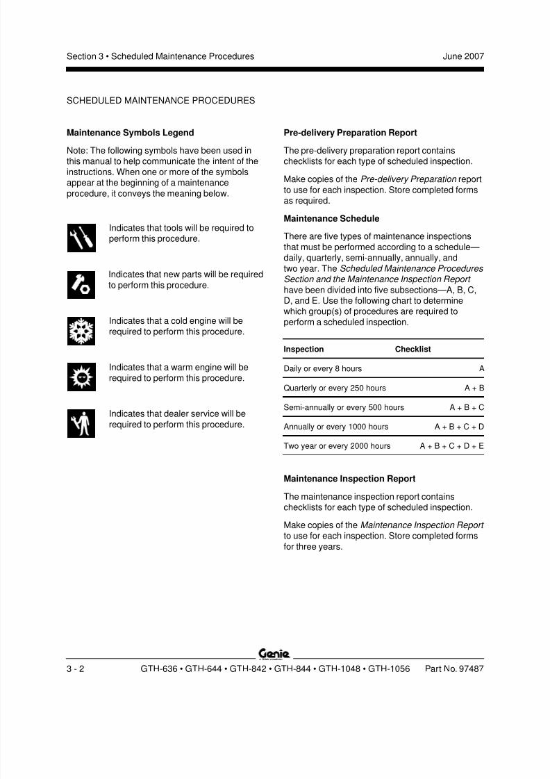
Maintenance Symbols LegendNote: The following symbols have been used inthis manual to help communicate the intent of the
instructions. When one or more of the symbolsappear at the beginning of a maintenance
procedure, it conveys the meaning below.
Indicates that tools will be required toperform this procedure.
Indicates that new parts will be requiredto perform this procedure.
Indicates that a cold engine will be
required to perform this procedure.
Indicates that a warm engine will be
required to perform this procedure.
Indicates that dealer service will be
required to perform this procedure.
Pre-delivery Preparation ReportThe pre-delivery preparation report containschecklists for each type of scheduled inspection.
Make copies of the Pre-delivery Preparation report
to use for each inspection. Store completed formsas required.
Maintenance Schedule
There are five types of maintenance inspections
that must be performed according to a schedule—daily, quarterly, semi-annually, annually, and
two year. The Scheduled Maintenance Procedures Section and the Maintenance Inspection Report
have been divided into five subsections—A, B, C,D, and E. Use the following chart to determinewhich group(s) of procedures are required to
perform a scheduled inspection.
Inspection Checklist
Daily or every 8 hours A
Quarterly or every 250 hours A + B
Semi-annually or every 500 hours A + B + C
Annually or every 1000 hours A + B + C + D
Two year or every 2000 hours A + B + C + D + E
Maintenance Inspection Report
The maintenance inspection report containschecklists for each type of scheduled inspection.
Make copies of the Maintenance Inspection Report to use for each inspection. Store completed forms
for three years.
SCHEDULED MAINTENANCE PROCEDURES
8/14/2019 Genie Manual de Servicio Gth-844
http://slidepdf.com/reader/full/genie-manual-de-servicio-gth-844 33/196
Genie Industries USA18340 NE 76th StreetPO Box 97030Redmond, WA 98073-9730(425) 881-1800
Copyright © 2002 by Genie Industries. Genie® is a registered trademark of GenieIndustries. Rev B
Genie UKThe Maltings, Wharf Road
Grantham, LincolnshireNG31- 6BH England
(44) 1476-584333
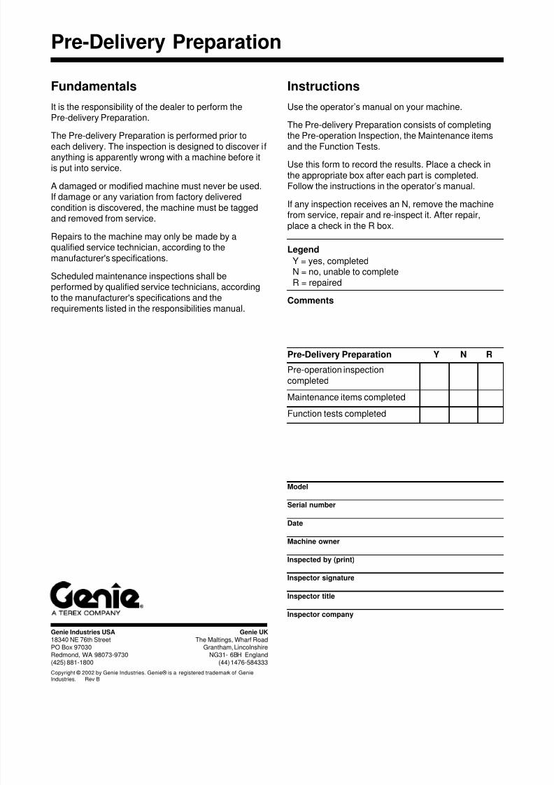
Pre-Delivery Preparation
Pre-Delivery Preparation Y N R
Pre-operation inspection
completed
Maintenance items completed
Function tests completed
Model
Serial number
Date
Machine owner
Inspected by (print)
Inspector signature
Inspector title
Inspector company
Instructions
Use the operator’s manual on your machine.
The Pre-delivery Preparation consists of completing
the Pre-operation Inspection, the Maintenance itemsand the Function Tests.
Use this form to record the results. Place a check in
the appropriate box after each part is completed.Follow the instructions in the operator’s manual.
If any inspection receives an N, remove the machinefrom service, repair and re-inspect it. After repair,
place a check in the R box.
Legend
Y = yes, completed
N = no, unable to completeR = repaired
Comments
Fundamentals
It is the responsibility of the dealer to perform thePre-delivery Preparation.
The Pre-delivery Preparation is performed prior toeach delivery. The inspection is designed to discover ifanything is apparently wrong with a machine before itis put into service.
A damaged or modified machine must never be used.If damage or any variation from factory delivered
condition is discovered, the machine must be taggedand removed from service.
Repairs to the machine may only be made by aqualified service technician, according to the
manufacturer's specifications.
Scheduled maintenance inspections shall beperformed by qualified service technicians, according
to the manufacturer's specifications and therequirements listed in the responsibilities manual.

8/14/2019 Genie Manual de Servicio Gth-844
http://slidepdf.com/reader/full/genie-manual-de-servicio-gth-844 34/196
Section 3 • Scheduled Maintenance Procedures June 2007
3 - 4 GTH-636 • GTH-644 • GTH-842 • GTH-844 • GTH-1048 • GTH-1056 Part No. 97487
This page intentionally left blank.
8/14/2019 Genie Manual de Servicio Gth-844
http://slidepdf.com/reader/full/genie-manual-de-servicio-gth-844 35/196
Section 3 • Scheduled Maintenance ProceduresJune 2007
Part No. 97487 GTH-636 • GTH-644 • GTH-842 • GTH-844 • GTH-1048 • GTH-1056 3 - 5
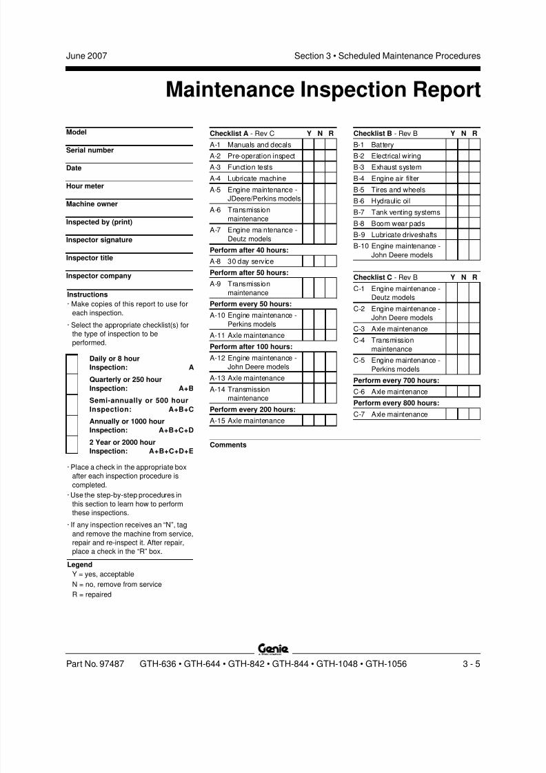
Maintenance Inspection Report
Checklist B - Rev B Y N RB-1 Battery
B-2 Electrical wiring
B-3 Exhaust system
B-4 Engine air filter
B-5 Tires and wheels
B-6 Hydraulic oil
B-7 Tank venting systems
B-8 Boom wear pads
B-9 Lubricate driveshafts
B-10 Engine maintenance -
John Deere models
Checklist C - Rev B Y N R
C-1 Engine maintenance -
Deutz models
C-2 Engine maintenance -
John Deere models
C-3 Axle maintenance
C-4 Transmission
maintenance
C-5 Engine maintenance -
Perkins models
Perform every 700 hours:
C-6 Axle maintenance
Perform every 800 hours:C-7 Axle maintenance
Checklist A - Rev C Y N RA-1 Manuals and decals
A-2 Pre-operation inspect
A-3 Function tests
A-4 Lubricate machine
A-5 Engine maintenance -
JDeere/Perkins models
A-6 Transmission
maintenance
A-7 Engine maintenance -
Deutz models
Perform after 40 hours:
A-8 30 day service
Perform after 50 hours:
A-9 Transmission
maintenance
Perform every 50 hours:
A-10 Engine maintenance -
Perkins models
A-11 Axle maintenance
Perform after 100 hours:
A-12 Engine maintenance -
John Deere models
A-13 Axle maintenance
A-14 Transmission
maintenance
Perform every 200 hours:
A-15 Axle maintenance
Instructions
· Make copies of this report to use for
each inspection.
· Select the appropriate checklist(s) for
the type of inspection to be
performed.
Daily or 8 hour
Inspection: A
Quarterly or 250 hour
Inspection: A+B
Semi-annually or 500 hour
Inspection: A+B+C
Annually or 1000 hour
Inspection: A+B+C+D
2 Year or 2000 hour
Inspection: A+B+C+D+E
· Place a check in the appropriate box
after each inspection procedure is
completed.
· Use the step-by-step procedures in
this section to learn how to perform
these inspections.
· If any inspection receives an “N”, tag
and remove the machine from service,
repair and re-inspect it. After repair,place a check in the “R” box.
Legend
Y = yes, acceptable
N = no, remove from service
R = repaired
Model
Serial number
Date
Hour meter
Machine owner
Inspected by (print)
Inspector signature
Inspector title
Inspector company
Comments

8/14/2019 Genie Manual de Servicio Gth-844
http://slidepdf.com/reader/full/genie-manual-de-servicio-gth-844 36/196
Section 3 • Scheduled Maintenance Procedures June 2007
3 - 6 GTH-636 • GTH-644 • GTH-842 • GTH-844 • GTH-1048 • GTH-1056 Part No. 97487
Instructions
· Make copies of this report to use for
each inspection.
· Select the appropriate checklist(s) for
the type of inspection to be
performed.
Daily or 8 hour
Inspection: A
Quarterly or 250 hour
Inspection: A+B
Semi-annually or 500 hour
Inspection: A+B+C
Annually or 1000 hour
Inspection: A+B+C+D
2 Year or 2000 hour
Inspection: A+B+C+D+E
· Place a check in the appropriate box
after each inspection procedure is
completed.
· Use the step-by-step procedures in
this section to learn how to perform
these inspections.
· If any inspection receives an “N”, tag
and remove the machine from service,
repair and re-inspect it. After repair,place a check in the “R” box.
Legend
Y = yes, acceptable
N = no, remove from service
R = repaired
Model
Serial number
Date
Hour meter
Machine owner
Inspected by (print)
Inspector signature
Inspector title
Inspector company
MAINTENANCE INSPECTION REPORT
Checklist D - Rev B Y N RD-1 Forks
D-2 Sequencing chains
D-3 Hydraulic return filter
D-4 Engine maintenance -
Deutz models
D-5 Transmission
D-6 Axle maintenance
D-7 Engine maintenance -
Perkins models
Perform every 1500 hours:
D-8 Engine maintenance -
Deutz models
Checklist E - Rev C Y N RE-1 Hydraulic oil
E-2 Engine maintenance -
John Deere models
E-3 Engine maintenance -
Perkins models
Perform every 3000 hours:
E-4 Engine maintenance -
Perkins models
Perform every 4000 hours:
E-5 Engine maintenance -
Perkins models
Perform every 4500 hours:
E-6 Engine maintenance -John Deere models
Perform every 6000 hours:
E-7 Engine maintenance -
Perkins models
Perform every 12,000 hours:
E-8 Engine maintenance -
Deutz models
E-9 Engine maintenance -
Perkins models
Comments
8/14/2019 Genie Manual de Servicio Gth-844
http://slidepdf.com/reader/full/genie-manual-de-servicio-gth-844 37/196
REV C
Section 3 • Scheduled Maintenance ProceduresJune 2007
Part No. 97487 GTH-636 • GTH-644 • GTH-842 • GTH-844 • GTH-1048 • GTH-1056 3 - 7
A-1Inspect the Manuals and Decals
Note: Genie specifications require that thisprocedure be performed every 8 hours or daily,whichever comes first.
Maintaining the operator’s and safety manuals in
good condition is essential to safe machineoperation. Manuals are included with eachmachine and should be stored in the container
provided in the operator's compartment. Anillegible or missing manual will not provide safety
and operational information necessary for a safeoperating condition.
In addition, maintaining all of the safety andinstructional decals in good condition is mandatory
for safe machine operation. Decals alert operatorsand personnel to the many possible hazards
associated with using this machine. They alsoprovide users with operation and maintenanceinformation. An illegible decal will fail to alert
personnel of a procedure or hazard and couldresult in unsafe operating conditions.
1 Check to make sure that the operator's andsafety manuals are present and complete in the
storage container in the operator'scompartment.
2 Examine the pages of each manual to be surethat they are legible and in good condition.
Result: The operator's manual is appropriate for
the machine and all manuals are legible and ingood condition.
Result: The operator's manual is notappropriate for the machine or all manuals are
not in good condition or is illegible. Remove themachine from service until the manual is
replaced.
Checklist A Procedures
3 Open the operator's manual to the decalsinspection section. Carefully and thoroughlyinspect all decals on the machine for legibilityand damage.
Result: The machine is equipped with all
required decals, and all decals are legible and
in good condition.
Result: The machine is not equipped with allrequired decals, or one or more decals are
illegible or in poor condition. Remove themachine from service until the decals arereplaced.
4 Always return the manuals to the storagecontainer after use.
Note: Contact your authorized Genie distributor or
Genie Industries if replacement manuals or decalsare needed.
8/14/2019 Genie Manual de Servicio Gth-844
http://slidepdf.com/reader/full/genie-manual-de-servicio-gth-844 38/196
REV C
Section 3 • Scheduled Maintenance Procedures June 2007
3 - 8 GTH-636 • GTH-644 • GTH-842 • GTH-844 • GTH-1048 • GTH-1056 Part No. 97487
CHECKLIST A PROCEDURES
A-2Perform Pre-operation Inspection
Note: Genie specifications require that thisprocedure be performed every 8 hours or daily,whichever comes first.
Completing a Pre-operation Inspection is essential
to safe machine operation. The Pre-operationInspection is a visual inspection performed by theoperator prior to each work shift. The inspection is
designed to discover if anything is apparentlywrong with a machine before the operator performs
the function tests. The Pre-operation Inspectionalso serves to determine if routine maintenance
procedures are required.
Complete information to perform this procedure is
available in the appropriate operator's manual.Refer to the Operator's Manual on your machine.
A-3Perform Function Tests
Note: Genie specifications require that thisprocedure be performed every 8 hours or daily,whichever comes first.
Completing the function tests is essential to safe
machine operation. Function tests are designed todiscover any malfunctions before the machine isput into service. A malfunctioning machine must
never be used. If malfunctions are discovered, themachine must be tagged and removed from
service.
Complete information to perform this procedure is
available in the appropriate operator's manual.Refer to the Operator's Manual on your machine.
8/14/2019 Genie Manual de Servicio Gth-844
http://slidepdf.com/reader/full/genie-manual-de-servicio-gth-844 39/196
REV C
Section 3 • Scheduled Maintenance ProceduresJune 2007
Part No. 97487 GTH-636 • GTH-644 • GTH-842 • GTH-844 • GTH-1048 • GTH-1056 3 - 9
CHECKLIST A PROCEDURES
A-4Lubricate the Machine
Note: Genie specifications require that thisprocedure be performed every 8 hours or daily,
whichever comes first.
Greasing the specified locations is essential for
good machine performance and service life.Operating the machine with little or no grease
may cause the machine to perform poorly and
continued use may cause component damage.
GTH-644, GTH-842 and GTH-844:
1 Fully extend the boom. Raise the boom as
needed.
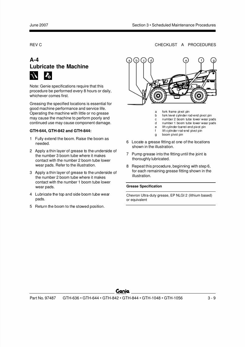
2 Apply a thin layer of grease to the underside ofthe number 3 boom tube where it makescontact with the number 2 boom tube lowerwear pads. Refer to the illustration.
3 Apply a thin layer of grease to the underside of
the number 2 boom tube where it makes
contact with the number 1 boom tube lowerwear pads.
4 Lubricate the top and side boom tube wearpads.
5 Return the boom to the stowed position.
a fork frame pivot pinb fork level cylinder rod-end pivot pinc number 2 boom tube lower wear padsd number 1 boom tube lower wear padse lift cylinder barrel-end pivot pinf lift cylinder rod-end pivot ping boom pivot pin
6 Locate a grease fitting at one of the locationsshown in the illustration.
7 Pump grease into the fitting until the joint is
thoroughly lubricated.
8 Repeat this procedure, beginning with step 6,for each remaining grease fitting shown in the
illustration.
Grease Specification
Chevron Ultra-duty grease, EP NLGI 2 (lithium based)
or equivalent
b e f gca d

8/14/2019 Genie Manual de Servicio Gth-844
http://slidepdf.com/reader/full/genie-manual-de-servicio-gth-844 40/196
REV C
Section 3 • Scheduled Maintenance Procedures June 2007
3 - 10 GTH-636 • GTH-644 • GTH-842 • GTH-844 • GTH-1048 • GTH-1056 Par t No. 97487
GTH-636, GTH-1048 and GTH-1056:1 Fully extend the boom. Raise the boom as
needed.
2 Locate the grease fittings at both sides of all
boom tubes except the innermost tube. Refer tothe illustration.
3 Pump grease into the fittings until the innerboom rollers are thoroughly lubricated.
4 Lubricate the top boom tube wear pads.
Note: Do not lubricate the side wear pads at the
boom rollers, if equipped.
5 Return the boom to the stowed position.
6 Locate a grease fitting at one of the locationsshown in the illustration.
7 Pump grease into the fitting until the joint is
thoroughly lubricated.
8 Repeat this procedure, beginning with step 6,for each remaining grease fitting shown in the
illustration.
GTH-1048 and GTH-1056:
9 Locate the grease fittings on the stabilizer frameat the front of the machine.
10 Pump grease into each fitting until the joints are
thoroughly lubricated.
11 Locate the grease fittings on the outriggers atthe front of the machine.
12 Pump grease into each fitting until the joints are
thoroughly lubricated.
Grease Specification
Chevron Ultra-duty grease, EP NLGI 2 (lithium based)
or equivalent
a fork frame pivot pinb fork level cylinder rod-end pivot pinc fork level cylinder barrel-end pivot pin
d boom grease fittingse lift cylinder barrel-end pivot pinf lift cylinder rod-end pivot ping boom pivot pinh outrigger pivot pin
(GTH-1048 and GTH-1056)i outrigger frame
(GTH-1048 and GTH-1056)
CHECKLIST A PROCEDURES
d fca b
i
h
e g

8/14/2019 Genie Manual de Servicio Gth-844
http://slidepdf.com/reader/full/genie-manual-de-servicio-gth-844 41/196
REV C
Section 3 • Scheduled Maintenance ProceduresJune 2007
Part No. 97487 GTH-636 • GTH-644 • GTH-842 • GTH-844 • GTH-1048 • GTH-1056 3 - 11
A-5Perform Engine Maintenance -John Deere and Perkins Models
Note: Engine specifications require that this
procedure be performed every 8 hours or daily,whichever comes first.
Required maintenance procedures and additionalengine information is available in the
John Deere 4045T270 Operator's Manual (John Deere part number OMRG25204) OR the
John Deere 4045T275 Operator's Manual (John Deere part number OMRG33324) OR the
Perkins 1104 Operation and Maintenance Manual (Perkins part number SEBU7833-01).
John Deere 4045T270 Operator's Manual
Genie part number 97492
John Deere 4045T275 Operator's Manual
Genie part number 108444
Perkins 1104 Operation and Maintenance Manual
Genie part number 117765
CHECKLIST A PROCEDURES
A-6Perform TransmissionMaintenance
Note: Transmission specifications require that thisprocedure be performed every 8 hours or daily,whichever comes first.
GTH-636, GTH-644, GTH-842 and GTH-844:
Required maintenance procedures and additionaltransmission information is available in the
Dana T12000 Maintenance Manual (Dana part number 0109).
Dana T12000 Maintenance Manual
Genie part number 97489
GTH-1048 and GTH-1056:
Required maintenance procedures and additionalTransmission information is available in the
Dana T20000 Maintenance Manual (Dana part number 0202).
Dana T20000 Maintenance Manual
Genie part number 115025
8/14/2019 Genie Manual de Servicio Gth-844
http://slidepdf.com/reader/full/genie-manual-de-servicio-gth-844 42/196
REV C
Section 3 • Scheduled Maintenance Procedures June 2007
3 - 12 GTH-636 • GTH-644 • GTH-842 • GTH-844 • GTH-1048 • GTH-1056 Par t No. 97487
CHECKLIST A PROCEDURES
A-7Perform Engine Maintenance -Deutz Models
Note: Engine specifications require that this
procedure be performed every 10 hours or daily,whichever comes first.
Required maintenance procedures and additionalengine information is available in the
Deutz 2012 Operation Manual (Deutz part number 0297 9912).
Deutz 2012 Operation Manual
Genie part number 108746
A-8Perform 30 Day Service
The 30 day maintenance procedure is a one-time
sequence of procedures to be performed after thefirst 30 days or 40 hours of usage. After this
interval, refer to the maintenance checklists forcontinued scheduled maintenance.
1 Perform the following maintenance procedures:
John Deere models:
· A-12 Perform Engine Maintenance -John Deere Models
· B-5 Inspect the Tires, Wheels andLug Nut Torque
· D-3 Replace the Hydraulic Tank
Return Filter Element
Deutz models:
· B-5 Inspect the Tires, Wheels andLug Nut Torque
· D-3 Replace the Hydraulic TankReturn Filter Element
· D-4 Perform Engine Maintenance -
Deutz Models
Perkins models:
· B-5 Inspect the Tires, Wheels andLug Nut Torque
· D-3 Replace the Hydraulic Tank
Return Filter Element
8/14/2019 Genie Manual de Servicio Gth-844
http://slidepdf.com/reader/full/genie-manual-de-servicio-gth-844 43/196
REV C
Section 3 • Scheduled Maintenance ProceduresJune 2007
Part No. 97487 GTH-636 • GTH-644 • GTH-842 • GTH-844 • GTH-1048 • GTH-1056 3 - 13
CHECKLIST A PROCEDURES
A-9Perform TransmissionMaintenanceGTH-636, GTH-644, GTH-842 and GTH-844
Note: Transmission specifications require that thisone-time procedure be performed after 50 hours ofoperation.
Required maintenance procedures and additional
transmission information is available in theDana T12000 Maintenance Manual (Dana part number 0109).
Dana T12000 Maintenance Manual
Genie part number 97489
A-10Perform Engine Maintenance -Perkins Models
Note: Engine specifications require that this
procedure be performed every 50 hours or weekly,whichever comes first.
Required maintenance procedures and additionalengine information is available in the
Perkins 1104 Operation and Maintenance Manual (Perkins part number SEBU7833-01).
Perkins 1104 Operation and Maintenance Manual
Genie part number 117765
8/14/2019 Genie Manual de Servicio Gth-844
http://slidepdf.com/reader/full/genie-manual-de-servicio-gth-844 44/196
REV C
Section 3 • Scheduled Maintenance Procedures June 2007
3 - 14 GTH-636 • GTH-644 • GTH-842 • GTH-844 • GTH-1048 • GTH-1056 Par t No. 97487
A-11Perform Axle Maintenance
Note: Axle specifications require that this
procedure be performed every 50 hours ormonthly, whichever comes first.
GTH-636, GTH-644, GTH-842 and GTH-844:
Required maintenance procedures and additionalaxle information is available in the
Dana 212 Axle Maintenance and Repair Manual (Dana part number 0247).
Dana 212 Axle Maintenance and Repair Manual
Genie part number 97488
GTH-1048 and GTH-1056:
Required maintenance procedures and additionalaxle information is available in the
Dana 213 Axle Maintenance and Repair Manual
(Dana part number 0243).
Dana 213 Axle Maintenance and Repair Manual
Genie part number 115026
A-12Perform Engine Maintenance -John Deere Models
Note: Engine specifications requires that this one-
time procedure be performed after 100 hours ofoperation.
Required maintenance procedures and additionalengine information is available in the
John Deere 4045T270 Operator's Manual (John Deere part number OMRG25204) OR the
John Deere 4045T275 Operator's Manual (John Deere part number OMRG33324).
John Deere 4045T270 Operator's Manual
Genie part number 97492
John Deere 4045T275 Operator's Manual
Genie part number 108444
CHECKLIST A PROCEDURES
8/14/2019 Genie Manual de Servicio Gth-844
http://slidepdf.com/reader/full/genie-manual-de-servicio-gth-844 45/196
REV C
Section 3 • Scheduled Maintenance ProceduresJune 2007
Part No. 97487 GTH-636 • GTH-644 • GTH-842 • GTH-844 • GTH-1048 • GTH-1056 3 - 15
A-13Perform Axle Maintenance
Note: Axle specifications require that this one-time
procedure be performed after 100 hours ofoperation.
GTH-636, GTH-644, GTH-842 and GTH-844:
Required maintenance procedures and additionalaxle information is available in the
Dana 212 Axle Maintenance and Repair Manual (Dana part number 0247).
Dana 212 Axle Maintenance and Repair Manual
Genie part number 97488
GTH-1048 and GTH-1056:
Required maintenance procedures and additionalaxle information is available in the
Dana 213 Axle Maintenance and Repair Manual
(Dana part number 0243).
Dana 213 Axle Maintenance and Repair Manual
Genie part number 115026
CHECKLIST A PROCEDURES
A-14Perform TransmissionMaintenanceGTH-636, GTH-644, GTH-842 and GTH-844
Note: Transmission specifications requires that thisone-time procedure be performed after 100 hoursof operation.
Required maintenance procedures and additional
transmission information is available in theDana T12000 Maintenance Manual (Dana part number 0109).
Dana T12000 Maintenance Manual
Genie part number 97489

8/14/2019 Genie Manual de Servicio Gth-844
http://slidepdf.com/reader/full/genie-manual-de-servicio-gth-844 46/196
REV C
Section 3 • Scheduled Maintenance Procedures June 2007
3 - 16 GTH-636 • GTH-644 • GTH-842 • GTH-844 • GTH-1048 • GTH-1056 Par t No. 97487
CHECKLIST A PROCEDURES
A-15Perform Axle Maintenance
Note: Axle specifications requires that this
procedure be performed every 200 hours ofoperation.
GTH-636, GTH-644, GTH-842 and GTH-844:
Required maintenance procedures and additionalaxle information is available in the
Dana 212 Axle Maintenance and Repair Manual (Dana part number 0247).
Dana 212 Axle Maintenance and Repair Manual
Genie part number 97488
GTH-1048 and GTH-1056:
Required maintenance procedures and additionalaxle information is available in the
Dana 213 Axle Maintenance and Repair Manual
(Dana part number 0243).
Dana 213 Axle Maintenance and Repair Manual
Genie part number 115026
8/14/2019 Genie Manual de Servicio Gth-844
http://slidepdf.com/reader/full/genie-manual-de-servicio-gth-844 47/196
REV B
Section 3 • Scheduled Maintenance ProceduresJune 2007
Part No. 97487 GTH-636 • GTH-644 • GTH-842 • GTH-844 • GTH-1048 • GTH-1056 3 - 17
B-1Inspect the Battery
Note: Genie requires that this procedure be
performed every 250 hours or quarterly, whichevercomes first.
Proper battery condition is essential to goodengine performance and operational safety.
Damaged cables and connections can result in
engine component damage and hazardousconditions.
Electrocution hazard. Contact with
hot or live circuits could result indeath or serious injury. Remove all
rings, watches and other jewelry.
Bodily injury hazard. Batteriescontain acid. Avoid spilling or
contacting battery acid. Neutralizebattery acid spills with baking soda
and water.
1 Put on protective clothing and eye wear.
2 Be sure that the battery cable connections arefree of corrosion.
Note: Adding terminal protectors and a corrosionpreventative sealant will help eliminate corrosionon the battery terminals and cables.
3 Be sure that the battery hold-downs and cable
connections are tight.
B-2Inspect the Electrical Wiring
Note: Genie requires that this procedure be
performed every 250 hours or quarterly, whichevercomes first.
Maintaining electrical wiring in good condition isessential to safe operation and good machine
performance. Failure to find and replace burnt,
chafed, corroded or pinched wires could result inunsafe operating conditions and may causecomponent damage.
Electrocution hazard. Contact withhot or live circuits could result in
death or serious injury. Remove allrings, watches and other jewelry.
1 Inspect the following areas for burnt, chafed,
corroded and loose wires:
· Inside of the operator's compartment
· Underside of the chassis
· Boom assembly
2 Inspect for a liberal coating of dielectric greasein the following locations:
·All harness connectors
3 Start the engine and raise the boom so there isenough room to access and remove all thecovers attached to the chassis.
Checklist B Procedures
8/14/2019 Genie Manual de Servicio Gth-844
http://slidepdf.com/reader/full/genie-manual-de-servicio-gth-844 48/196
REV B
Section 3 • Scheduled Maintenance Procedures June 2007
3 - 18 GTH-636 • GTH-644 • GTH-842 • GTH-844 • GTH-1048 • GTH-1056 Part No. 97487
4 Attach a lifting strap from an overhead crane tothe boom. Support the boom. Do not apply anylifting pressure.
5 Remove all engine covers, hydraulic tank
covers and chassis covers.
Crushing hazard. Death or seriousinjury could result if the boom
should unexpectedly fall whileworking underneath the boom. Do
not stand or work beneath a boomthat is not properly supported.
6 Inspect the following areas for burnt, chafed,
corroded, pinched and loose wires:
· Engine
·Transmission
· Manifolds
·Chassis
7 Inspect for a liberal coating of dielectric greasein all connections between the engine,
transmission and the operator's compartment.
8 Install all covers removed in step 5.
9 Remove the lifting strap from the overheadcrane.
10 Start the engine and lower the boom to thestowed position. Turn the machine off.
B-3Check the Exhaust System
Note: Genie requires that this procedure be
performed every 250 hours or quarterly, whichevercomes first.
Maintaining the exhaust system is essential togood engine performance and service life. Running
the engine with a damaged or leaking exhaust
system can cause component damage and unsafeoperating conditions.
Bodily injury hazard. Do not
inspect while the engine isrunning. Remove the key to
secure from operation.
Bodily injury hazard. Beware ofhot engine components. Contact
with hot engine components maycause severe burns.
1 Remove the center engine cover and set aside.
2 Open the right side engine access cover.
3 Be sure that all fasteners are tight.
4 Inspect all welds for cracks.
5 Inspect for exhaust leaks; i.e., carbon builduparound seams and joints.
6 Close the right side engine access cover. Installthe center engine access cover.
CHECKLIST B PROCEDURES
8/14/2019 Genie Manual de Servicio Gth-844
http://slidepdf.com/reader/full/genie-manual-de-servicio-gth-844 49/196
REV B
Section 3 • Scheduled Maintenance ProceduresJune 2007
Part No. 97487 GTH-636 • GTH-644 • GTH-842 • GTH-844 • GTH-1048 • GTH-1056 3 - 19
B-4Inspect the Engine Air Filter
Note: Genie requires that this procedure be
performed every 250 hours or quarterly, whichevercomes first. Perform this procedure more often if
dusty conditions exist.
Maintaining the engine air filter in good condition is
essential to good engine performance and service
life. Failure to perform this procedure can lead topoor engine performance and component damage.
Note: Perform this procedure with the engine off.
1 Release the latches on the front cover of the air
cleaner assembly. Remove the cover.
2 Gently twist and pull out the external or primaryfilter element.
3 Remove the inner or secondary filter element.
4 Clean the inside of the canister and the gasketwith a damp cloth.
5 Inspect the primary and secondary air filter
elements. If needed, blow from the insideout using low pressure dry compressed air,or carefully tap out dust.
6 Install the secodnary filter element first, theninstall the primary filter element.
7 Install the front cover onto the air cleaner
assembly and secure the latches.
CHECKLIST B PROCEDURES
B-5Inspect the Tires, Wheels andLug Nut Torque
Note: Genie requires that this procedure be
performed every 250 hours or quarterly, whichevercomes first.
Maintaining the tires and wheels in goodcondition, including proper wheel fastener torque,
is essential to safe operation and goodperformance. Tire and/or wheel failure could result
in a machine tip-over. Component damage mayalso result if problems are not discovered andrepaired in a timely fashion.
Bodily injury hazard. Anoverinflated tire can explode and
could result in death or seriousinjury.
Tip over hazard. Do not usetemporary flat tire repair products.
Note: The tires on some machines are foam filledand do not need air added to them.
1 Check all tire treads and sidewalls for cuts,
cracks, punctures and unusual wear.
2 Check each wheel for damage, bends andcracks.
3 Check each lug nut for proper torque. Refer toSection 2, Specifications .

8/14/2019 Genie Manual de Servicio Gth-844
http://slidepdf.com/reader/full/genie-manual-de-servicio-gth-844 50/196
REV B
Section 3 • Scheduled Maintenance Procedures June 2007
3 - 20 GTH-636 • GTH-644 • GTH-842 • GTH-844 • GTH-1048 • GTH-1056 Part No. 97487
CHECKLIST B PROCEDURES
Models with air or calcium chloride filled tires:4 Put on protective clothing and eye wear.
5 Rotate the wheel until the tire stem is at the 12o'clock position.
B-6Perform Hydraulic Oil Analysis
Note: Genie requires that this procedure be
performed every 250 hours or quarterly, whichevercomes first.
Replacement or testing of the hydraulic oil isessential for good machine performance and
service life. Dirty oil may cause the machine to
perform poorly and continued use may causecomponent damage. Extremely dirty conditionsmay require oil changes to be performed more
often. Refer to Section 2, Specifications .
Note: Before replacing the hydraulic oil, the oil may
be tested by an oil distributor for specific levels ofcontamination to verify that changing the oil is
necessary. If the hydraulic oil is not replaced atthe two year inspection, test the oil quarterly.Replace the oil when it fails the test. See E-1,
Test or Replace the Hydraulic Oil.
a
a valve stem
6 Check the air pressure in the tire. Refer to
Section 2, Specifications .
Result - models with air-filled tires: The air
pressure meets specification. The tire is at thecorrectly filled level.Result - models with calcium chloride-filled
tires: The air pressure meets specification, anda small amount of calcium chloride mixtureleaks from the valve stem when checking the
air pressure. The tire is at the correctly filledlevel.
Result - models with air-filled tires: The airpressure does not meet specification. Add airuntil the air pressure meets specification.
Result - models with calcium chloride-filled
tires: The air pressure does not meetspecification OR the tire does not release any
calcium chloride mixture when checking the airpressure. Add calcium chloride mix to the tire
as needed until it begins to leak out whendepressing the valve stem, and add air until the
air pressure meets specification.
7 Repeat this procedure beginning with step 5 foreach remaining tire.
8/14/2019 Genie Manual de Servicio Gth-844
http://slidepdf.com/reader/full/genie-manual-de-servicio-gth-844 51/196
REV B
Section 3 • Scheduled Maintenance ProceduresJune 2007
Part No. 97487 GTH-636 • GTH-644 • GTH-842 • GTH-844 • GTH-1048 • GTH-1056 3 - 21
B-7Inspect the Fuel and HydraulicTank Cap Venting Systems
Note: Genie requires that this procedure be
performed every 250 hours or quarterly, whichevercomes first. Perform this procedure more often ifdusty conditions exist.
Free-breathing fuel and hydraulic tank caps are
essential for good machine performance andservice life. A dirty or clogged tank cap may cause
the machine to perform poorly and continued usemay cause component damage. Extremely dirtyconditions may require that the caps be inspected
more often.
Explosion and fire hazard. Engine
fuels are combustible. Perform thisprocedure in an open, well-
ventilated area away from heaters,sparks, flames and lighted
tobacco. Always have an
approved fire extinguisher withineasy reach.
Note: Perform this procedure with the engine off.
1 Remove the cap from the fuel tank.
2 Check for proper venting.
Result: Air passes through the fuel tank cap.
Proceed to step 4.
Result: If air does not pass through the cap,clean or replace the cap. Proceed to step 3.
Note: When checking for positive tank cap venting,air should pass freely through the cap.
3 Using a mild solvent, carefully wash the capventing system. Dry using low pressurecompressed air. Repeat this procedurebeginning with step 2.
4 Install the fuel tank cap onto the fuel tank.
5 Remove the breather cap from the hydraulictank.
6 Check for proper venting.
Result: Air passes through the fuel tank cap.
Proceed to step 8.
Result: If air does not pass through the cap,clean or replace the cap. Proceed to step 7.
Note: When checking for positive tank cap venting,air should pass freely through the cap.
7 Using a mild solvent, carefully wash the capventing system. Dry using low pressure
compressed air. Repeat this procedurebeginning with step 6.
8 Install the breather cap onto the hydraulic tank.
CHECKLIST B PROCEDURES
8/14/2019 Genie Manual de Servicio Gth-844
http://slidepdf.com/reader/full/genie-manual-de-servicio-gth-844 52/196
REV B
Section 3 • Scheduled Maintenance Procedures June 2007
3 - 22 GTH-636 • GTH-644 • GTH-842 • GTH-844 • GTH-1048 • GTH-1056 Part No. 97487
CHECKLIST B PROCEDURES
B-8Check the Boom Wear PadsGTH-644, GTH-842 and GTH-844
Note: Genie specifications require that this
procedure be performed every 250 hours ofoperation.
1 Extend the boom until the wear pads areaccessible.
2 Measure each upper wear pad.
Result: The measurement is within
specification.
Result: The measurement is less thanspecification. Replace both wear pads. Refer toRepair Procedure 1-2, How to Replace the
Boom Wear Pads .
2 Measure each side wear pad.
Result: The measurement is within
specification.
Result: The measurement is less thanspecification. Replace all side wear pads. Refer
to Repair Procedure 1-2, How to Replace the Boom Wear Pads .
2 Measure each lower wear pad.Result: The measurement is within
specification.
Result: The measurement is less thanspecification. Replace both wear pads. Refer to
Repair Procedure 1-2, How to Replace the Boom Wear Pads .
Boom Wear Pad Specifications,
GTH-644, GTH-842 and GTH-844
Upper wear pad thickness, minimum 9 / 16 inch
14.3 mm
Side wear pad thickness, minimum 3 / 8 inch
9.5 mm
Lower wear pad thickness, minimum 9 / 16 inch
14.3 mm
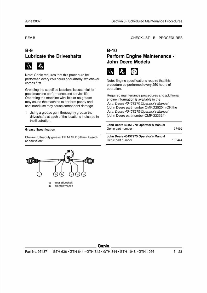
8/14/2019 Genie Manual de Servicio Gth-844
http://slidepdf.com/reader/full/genie-manual-de-servicio-gth-844 53/196
REV B
Section 3 • Scheduled Maintenance ProceduresJune 2007
Part No. 97487 GTH-636 • GTH-644 • GTH-842 • GTH-844 • GTH-1048 • GTH-1056 3 - 23
B-9Lubricate the Driveshafts
Note: Genie requires that this procedure be
performed every 250 hours or quarterly, whichevercomes first.
Greasing the specified locations is essential forgood machine performance and service life.
Operating the machine with little or no grease
may cause the machine to perform poorly andcontinued use may cause component damage.
1 Using a grease gun, thoroughly grease the
driveshafts at each of the locations indicated inthe illustration.
Grease Specification
Chevron Ultra-duty grease, EP NLGI 2 (lithium based)
or equivalent
aa ab bb
CHECKLIST B PROCEDURES
a rear driveshaftb frontd riveshaft
B-10Perform Engine Maintenance -John Deere Models
Note: Engine specifications require that this
procedure be performed every 250 hours ofoperation.
Required maintenance procedures and additionalengine information is available in the
John Deere 4045T270 Operator's Manual (John Deere part number OMRG25204) OR the
John Deere 4045T275 Operator's Manual (John Deere part number OMRG33324).
John Deere 4045T270 Operator's Manual
Genie part number 97492
John Deere 4045T275 Operator's Manual
Genie part number 108444
8/14/2019 Genie Manual de Servicio Gth-844
http://slidepdf.com/reader/full/genie-manual-de-servicio-gth-844 54/196
REV B
Section 3 • Scheduled Maintenance Procedures June 2007
3 - 24 GTH-636 • GTH-644 • GTH-842 • GTH-844 • GTH-1048 • GTH-1056 Part No. 97487
C-1Perform Engine Maintenance -Deutz Models
Note: Engine specifications require that thisprocedure be performed every 500 hours or semi-
annually, whichever comes first.
Required maintenance procedures and additional
engine information is available in the
Deutz 2012 Operation Manual (Deutz part number 0297 9912).
Deutz 2012 Operation Manual
Genie part number 108746
C-2Perform Engine Maintenance -John Deere Models
Note: Engine specifications require that this
procedure be performed every 500 hours or semi-annually, whichever comes first.
Required maintenance procedures and additionalengine information is available in the
John Deere 4045T270 Operator's Manual (John Deere part number OMRG25204) OR the
John Deere 4045T275 Operator's Manual (John Deere part number OMRG33324).
John Deere 4045T270 Operator's Manual
Genie part number 97492
John Deere 4045T275 Operator's Manual
Genie part number 108444
Checklist C Procedures

8/14/2019 Genie Manual de Servicio Gth-844
http://slidepdf.com/reader/full/genie-manual-de-servicio-gth-844 55/196
REV B
Section 3 • Scheduled Maintenance ProceduresJune 2007
Part No. 97487 GTH-636 • GTH-644 • GTH-842 • GTH-844 • GTH-1048 • GTH-1056 3 - 25
CHECKLIST C PROCEDURES
C-3Perform Axle Maintenance
Note: Axle specifications require that this
procedure be performed after 500 hours ofoperation.
GTH-636, GTH-644, GTH-842 and GTH-844:
Required maintenance procedures and additionalaxle information is available in the
Dana 212 Axle Maintenance and Repair Manual (Dana part number 0247).
Dana 212 Axle Maintenance and Repair Manual
Genie part number 97488
GTH-1048 and GTH-1056:
Required maintenance procedures and additionalaxle information is available in the
Dana 213 Axle Maintenance and Repair Manual
(Dana part number 0243).
Dana 213 Axle Maintenance and Repair Manual
Genie part number 115026
C-4Perform TransmissionMaintenanceGTH-1048 and GTH-1056
Note: Transmission specifications require that thisprocedure be performed every 500 hours or semi-annually, whichever comes first.
Required maintenance procedures and additional
transmission information is available in theDana T20000 Maintenance Manual (Dana part number 0202).
Dana T20000 Maintenance Manual
Genie part number 115025

8/14/2019 Genie Manual de Servicio Gth-844
http://slidepdf.com/reader/full/genie-manual-de-servicio-gth-844 56/196
REV B
Section 3 • Scheduled Maintenance Procedures June 2007
3 - 26 GTH-636 • GTH-644 • GTH-842 • GTH-844 • GTH-1048 • GTH-1056 Part No. 97487
C-5Perform Engine Maintenance -Perkins Models
Note: Engine specifications require that this
procedure be performed every 500 hours orannually, whichever comes first.
Required maintenance procedures and additionalengine information is available in the
Perkins 1104 Operation and Maintenance Manual (Perkins part number SEBU7833-01).
Perkins 1104 Operation and Maintenance Manual
Genie part number 117765
C-6Perform Axle Maintenance
Note: Axle specifications require that this
procedure be performed every 700 hours ofoperation.
GTH-636, GTH-644, GTH-842 and GTH-844:
Required maintenance procedures and additionalaxle information is available in the
Dana 212 Axle Maintenance and Repair Manual (Dana part number 0247).
Dana 212 Axle Maintenance and Repair Manual
Genie part number 97488
GTH-1048 and GTH-1056:
Required maintenance procedures and additionalaxle information is available in the
Dana 213 Axle Maintenance and Repair Manual
(Dana part number 0243).
Dana 213 Axle Maintenance and Repair Manual
Genie part number 115026
CHECKLIST C PROCEDURES
8/14/2019 Genie Manual de Servicio Gth-844
http://slidepdf.com/reader/full/genie-manual-de-servicio-gth-844 57/196
REV B
Section 3 • Scheduled Maintenance ProceduresJune 2007
Part No. 97487 GTH-636 • GTH-644 • GTH-842 • GTH-844 • GTH-1048 • GTH-1056 3 - 27
C-7Perform Axle Maintenance
Note: Axle specifications require that this
procedure be performed every 800 hours ofoperation.
GTH-636, GTH-644, GTH-842 and GTH-844:
Required maintenance procedures and additionalaxle information is available in the
Dana 212 Axle Maintenance and Repair Manual (Dana part number 0247).
Dana 212 Axle Maintenance and Repair Manual
Genie part number 97488
GTH-1048 and GTH-1056:
Required maintenance procedures and additionalaxle information is available in the
Dana 213 Axle Maintenance and Repair Manual
(Dana part number 0243).
Dana 213 Axle Maintenance and Repair Manual
Genie part number 115026
CHECKLIST C PROCEDURES
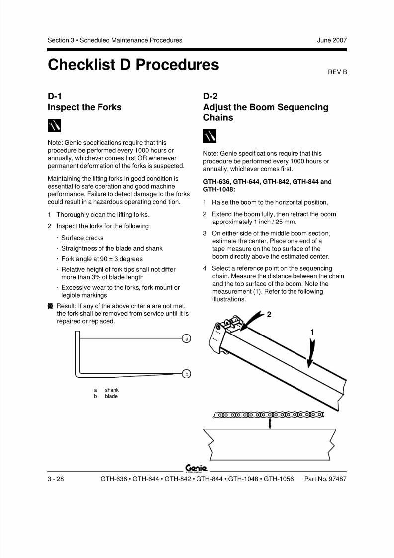
8/14/2019 Genie Manual de Servicio Gth-844
http://slidepdf.com/reader/full/genie-manual-de-servicio-gth-844 58/196
REV B
Section 3 • Scheduled Maintenance Procedures June 2007
3 - 28 GTH-636 • GTH-644 • GTH-842 • GTH-844 • GTH-1048 • GTH-1056 Part No. 97487
D-1Inspect the Forks
Note: Genie specifications require that this
procedure be performed every 1000 hours orannually, whichever comes first OR whenever
permanent deformation of the forks is suspected.
Maintaining the lifting forks in good condition is
essential to safe operation and good machine
performance. Failure to detect damage to the forkscould result in a hazardous operating condition.
1 Thoroughly clean the lifting forks.
2 Inspect the forks for the following:
· Surface cracks
· Straightness of the blade and shank
· Fork angle at 90 ± 3 degrees
· Relative height of fork tips shall not differmore than 3% of blade length
· Excessive wear to the forks, fork mount or
legible markings
Result: If any of the above criteria are not met,the fork shall be removed from service until it isrepaired or replaced.
D-2Adjust the Boom SequencingChains
Note: Genie specifications require that this
procedure be performed every 1000 hours orannually, whichever comes first.
GTH-636, GTH-644, GTH-842, GTH-844 andGTH-1048:
1 Raise the boom to the horizontal position.
2 Extend the boom fully, then retract the boom
approximately 1 inch / 25 mm.
3 On either side of the middle boom section,estimate the center. Place one end of a
tape measure on the top surface of theboom directly above the estimated center.
4 Select a reference point on the sequencing
chain. Measure the distance between the chainand the top surface of the boom. Note the
measurement (1). Refer to the followingillustrations.
Checklist D Procedures
1
2
a shankb blade
a
b

8/14/2019 Genie Manual de Servicio Gth-844
http://slidepdf.com/reader/full/genie-manual-de-servicio-gth-844 59/196
REV B
Section 3 • Scheduled Maintenance ProceduresJune 2007
Part No. 97487 GTH-636 • GTH-644 • GTH-842 • GTH-844 • GTH-1048 • GTH-1056 3 - 29
CHECKLIST D PROCEDURES
GTH-1056:1 Raise the boom to the horizontal position.
2 Extend the boom fully, then retract the boomapproximately 1 inch / 25 mm.
3 On either side of the number 2 boom tube,estimate the center. Place one end of a
tape measure on the top surface of theboom directly above the estimated center.
5 Move to the fork end of the same boom sectionthat was just measured.
6 Measure the distance between the top surfaceof the boom and the same reference point used
on the sequencing chain in step 4. Note themeasurement (2).
Result: The difference between measurements
1 and 2 is 0.25 to 0.5 inch / 6.35 to 12.7 mm.No adjustment to the chain is necessary.
Proceed to step 10.
Result: The difference between measurements
1 and 2 is less than a 0.25 inch / 6.35 mm ORis greater than 0.5 inch / 12.7 mm. The chainrequires adjustment. Proceed to step 7.
Note: The measurements taken in step 4 and step
6 must be taken from the same plane on the boom.
7 Working at the fork end of the large boom tube,
locate the adjustable chain anchor on the top ofboom section.
ba c
a nutb springc chain anchor
8 Place an adjustable wrench across the flat partof the chain, just ahead of the chain anchor.Tighten the wrench onto the chain.
9 Using a 1 7 / 16 inch wrench, adjust the nut as
required to tighten or loosen the chain. Repeatthis procedure beginning with step 4.
10 Using a feeler gauge, check the gap betweenthe coils of the spring. The gap should be no
less than 0.030 inch / 0.76 mm.
Note: The spring coils should never be collapsedcompletely.
a number 0 boom tubeb chain tensioner
c boom tube 2 extension chaind number 1 boom tubee boom tube 3 extension chainf number 2 boom tubeg number 3 boom tubeh front coveri chain roller (hidden from view) j boom roller (hidden from view)k support loopl extension cylinder
gc he
l k
GTH-1056
fda b
j ji j i
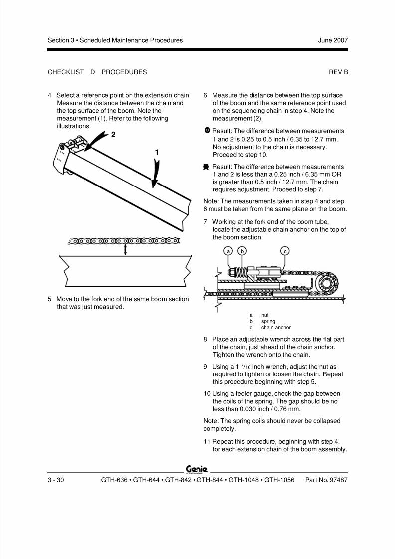
8/14/2019 Genie Manual de Servicio Gth-844
http://slidepdf.com/reader/full/genie-manual-de-servicio-gth-844 60/196
REV B
Section 3 • Scheduled Maintenance Procedures June 2007
3 - 30 GTH-636 • GTH-644 • GTH-842 • GTH-844 • GTH-1048 • GTH-1056 Part No. 97487
1
2
ba c
4 Select a reference point on the extension chain.Measure the distance between the chain andthe top surface of the boom. Note themeasurement (1). Refer to the following
illustrations.
6 Measure the distance between the top surfaceof the boom and the same reference point usedon the sequencing chain in step 4. Note themeasurement (2).
Result: The difference between measurements
1 and 2 is 0.25 to 0.5 inch / 6.35 to 12.7 mm.
No adjustment to the chain is necessary.Proceed to step 10.
Result: The difference between measurements1 and 2 is less than a 0.25 inch / 6.35 mm ORis greater than 0.5 inch / 12.7 mm. The chainrequires adjustment. Proceed to step 7.
Note: The measurements taken in step 4 and step6 must be taken from the same plane on the boom.
7 Working at the fork end of the boom tube,locate the adjustable chain anchor on the top of
the boom section.
CHECKLIST D PROCEDURES
5 Move to the fork end of the same boom sectionthat was just measured.
a nutb springc chain anchor
8 Place an adjustable wrench across the flat part
of the chain, just ahead of the chain anchor.Tighten the wrench onto the chain.
9 Using a 1 7 / 16 inch wrench, adjust the nut as
required to tighten or loosen the chain. Repeatthis procedure beginning with step 5.
10 Using a feeler gauge, check the gap betweenthe coils of the spring. The gap should be noless than 0.030 inch / 0.76 mm.
Note: The spring coils should never be collapsed
completely.
11 Repeat this procedure, beginning with step 4,for each extension chain of the boom assembly.
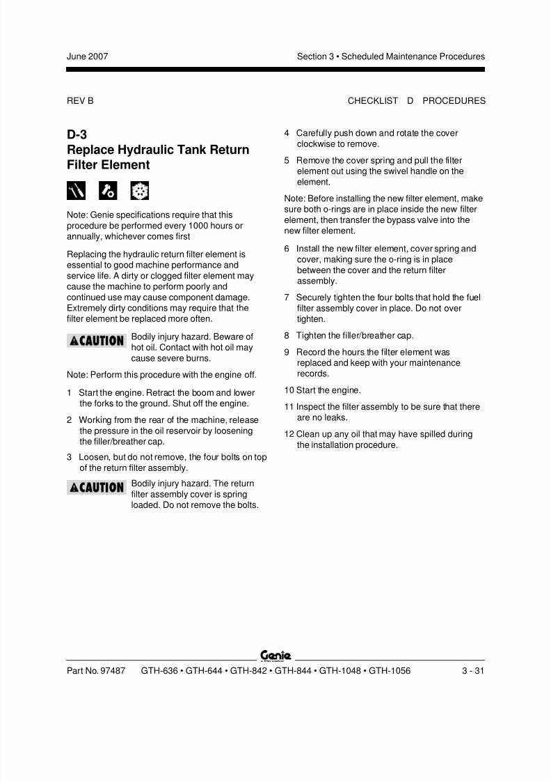
8/14/2019 Genie Manual de Servicio Gth-844
http://slidepdf.com/reader/full/genie-manual-de-servicio-gth-844 61/196

8/14/2019 Genie Manual de Servicio Gth-844
http://slidepdf.com/reader/full/genie-manual-de-servicio-gth-844 62/196
REV B
Section 3 • Scheduled Maintenance Procedures June 2007
3 - 32 GTH-636 • GTH-644 • GTH-842 • GTH-844 • GTH-1048 • GTH-1056 Part No. 97487
CHECKLIST D PROCEDURES
D-4Perform Engine Maintenance -Deutz Models
Note: Engine specifications require that thisprocedure be performed every 1000 hours or
annually, whichever comes first.
Required maintenance procedures and additional
engine information is available in the
Deutz 2012 Operation Manual (Deutz part number 0297 9912).
Deutz 2012 Operation Manual
Genie part number 108746
D-5Perform TransmissionMaintenance
Note: Transmission specifications require that thisprocedure be performed every 1000 hours orannually, whichever comes first.
GTH-636, GTH-644, GTH-842 and GTH-844:
Required maintenance procedures and additionaltransmission information is available in the
Dana T12000 Maintenance Manual (Dana part number 0109).
Dana T12000 Maintenance Manual
Genie part number 97489
GTH-1048 and GTH-1056:
Required maintenance procedures and additionaltransmission information is available in the
Dana T20000 Maintenance Manual (Dana part number 0202).
Dana T20000 Maintenance Manual
Genie part number 115025
8/14/2019 Genie Manual de Servicio Gth-844
http://slidepdf.com/reader/full/genie-manual-de-servicio-gth-844 63/196
REV B
Section 3 • Scheduled Maintenance ProceduresJune 2007
Part No. 97487 GTH-636 • GTH-644 • GTH-842 • GTH-844 • GTH-1048 • GTH-1056 3 - 33
D-6Perform Axle Maintenance
Note: Axle specifications require that this
procedure be performed every 1000 hours ofoperation.
GTH-636, GTH-644, GTH-842 and GTH-844:
Required maintenance procedures and additionalaxle information is available in the
Dana 212 Axle Maintenance and Repair Manual (Dana part number 0247).
Dana 212 Axle Maintenance and Repair Manual
Genie part number 97488
GTH-1048 and GTH-1056:
Required maintenance procedures and additionalaxle information is available in the
Dana 213 Axle Maintenance and Repair Manual
(Dana part number 0243).
Dana 213 Axle Maintenance and Repair Manual
Genie part number 115026
D-7Perform Engine Maintenance -Perkins Models
Note: Engine specifications require that this
procedure be performed every 1000 hours.
Required maintenance procedures and additional
engine information is available in thePerkins 1104 Operation and Maintenance Manual
(Perkins part number SEBU7833-01).
Perkins 1104 Operation and Maintenance Manual
Genie part number 117765
CHECKLIST D PROCEDURES
8/14/2019 Genie Manual de Servicio Gth-844
http://slidepdf.com/reader/full/genie-manual-de-servicio-gth-844 64/196
REV B
Section 3 • Scheduled Maintenance Procedures June 2007
3 - 34 GTH-636 • GTH-644 • GTH-842 • GTH-844 • GTH-1048 • GTH-1056 Part No. 97487
D-8Perform Engine Maintenance -Deutz Models
Note: Engine specifications require the valves tobe adjusted every 1500 hours of operation.
Required maintenance procedures and additionalengine information is available in the
Deutz 2012 Operation Manual
(Deutz part number 0297 9912).
Deutz 2012 Operation Manual
Genie part number 108746
CHECKLIST D PROCEDURES
8/14/2019 Genie Manual de Servicio Gth-844
http://slidepdf.com/reader/full/genie-manual-de-servicio-gth-844 65/196
REV C
Section 3 • Scheduled Maintenance ProceduresJune 2007
Part No. 97487 GTH-636 • GTH-644 • GTH-842 • GTH-844 • GTH-1048 • GTH-1056 3 - 35
E-1Test or Replace the Hydraulic Oil
Note: Genie specifications require that this
procedure be performed every 2000 hours or twoyears, whichever comes first
Replacement or testing of the hydraulic oil isessential for good machine performance and
service life. Dirty oil may cause the machine to
perform poorly and continued use may causecomponent damage. Extremely dirty conditionsmay require oil changes to be performed more
frequently. Refer to Section 2, Specifications .
Component damage hazard. The
work area and surfaces where thisprocedure will be performed must
be clean and free of debris thatcould get into the hydraulicsystem.
Note: Before replacing the hydraulic oil, the oil maybe tested by an oil distributor for specific levels of
contamination to verify that changing the oil isnecessary. If the hydraulic oil is not replaced atthe two year inspection, test the oil quarterly.
Replace the oil when it fails the test.
1 Lower the boom to the stowed position.
2 Remove oil cap from top of hydraulic tank.
3 Using an approved hand-operated pump, drainthe hydraulic tank into a suitable container.Refer to Section 2, Specifications .
Bodily injury hazard. Beware of
hot oil. Contact with hot oil maycause severe burns.
4 Remove the drain plug from the rear of the tank.
5 Rinse out the inside of the tank using a mild
solvent.
6 Install the drain plug and securely tighten. Donot over tighten.
7 Fill the tank with hydraulic oil until the fluid levelis in the center of the sight glass at the rear ofthe tank.
8 Clean up any oil that may have spilled.
Checklist E Procedures
8/14/2019 Genie Manual de Servicio Gth-844
http://slidepdf.com/reader/full/genie-manual-de-servicio-gth-844 66/196
REV C
Section 3 • Scheduled Maintenance Procedures June 2007
3 - 36 GTH-636 • GTH-644 • GTH-842 • GTH-844 • GTH-1048 • GTH-1056 Par t No. 97487
CHECKLIST E PROCEDURES
E-2Perform Engine Maintenance -John Deere Models
Note: Engine specifications require that this
procedure be performed every 2000 hours or twoyears, whichever comes first.
Required maintenance procedures and additionalengine information is available in the
John Deere 4045T270 Operator's Manual (John Deere part number OMRG25204) OR the
John Deere 4045T275 Operator's Manual (John Deere part number OMRG33324).
John Deere 4045T270 Operator's Manual
Genie part number 97492
John Deere 4045T275 Operator's Manual
Genie part number 108444
E-3Perform Engine Maintenance -Perkins Models
Note: Engine specifications require that this
procedure be performed every 2000 hours.
Required maintenance procedures and additional
engine information is available in thePerkins 1104 Operation and Maintenance Manual
(Perkins part number SEBU7833-01).
Perkins 1104 Operation and Maintenance Manual
Genie part number 117765
8/14/2019 Genie Manual de Servicio Gth-844
http://slidepdf.com/reader/full/genie-manual-de-servicio-gth-844 67/196
REV C
Section 3 • Scheduled Maintenance ProceduresJune 2007
Part No. 97487 GTH-636 • GTH-644 • GTH-842 • GTH-844 • GTH-1048 • GTH-1056 3 - 37
E-4Perform Engine Maintenance -Perkins Models
Note: Engine specifications require that this
procedure be performed every 3000 hours or twoyears, whichever comes first.
Required maintenance procedures and additionalengine information is available in the
Perkins 1104 Operation and Maintenance Manual (Perkins part number SEBU7833-01).
Perkins 1104 Operation and Maintenance Manual
Genie part number 117765
E-5Perform Engine Maintenance -Perkins Models
Note: Engine specifications require that this
procedure be performed every 4000 hours.
Required maintenance procedures and additional
engine information is available in thePerkins 1104 Operation and Maintenance Manual
(Perkins part number SEBU7833-01).
Perkins 1104 Operation and Maintenance Manual
Genie part number 117765
CHECKLIST E PROCEDURES
8/14/2019 Genie Manual de Servicio Gth-844
http://slidepdf.com/reader/full/genie-manual-de-servicio-gth-844 68/196
REV C
Section 3 • Scheduled Maintenance Procedures June 2007
3 - 38 GTH-636 • GTH-644 • GTH-842 • GTH-844 • GTH-1048 • GTH-1056 Par t No. 97487
CHECKLIST E PROCEDURES
E-6Perform Engine Maintenance -John Deere Models
Note: Engine specifications require that this
procedure be performed every 4500 hours or 60months, whichever comes first.
Required maintenance procedures and additionalengine information is available in the
John Deere 4045T270 Operator's Manual (John Deere part number OMRG25204) OR the
John Deere 4045T275 Operator's Manual (John Deere part number OMRG33324).
John Deere 4045T270 Operator's Manual
Genie part number 97492
John Deere 4045T275 Operator's Manual
Genie part number 108444
E-7Perform Engine Maintenance -Perkins Models
Note: Engine specifications require that this
procedure be performed every 6000 hours or everythree years, whichever comes first.
Required maintenance procedures and additionalengine information is available in the
Perkins 1104 Operation and Maintenance Manual (Perkins part number SEBU7833-01).
Perkins 1104 Operation and Maintenance Manual
Genie part number 117765

8/14/2019 Genie Manual de Servicio Gth-844
http://slidepdf.com/reader/full/genie-manual-de-servicio-gth-844 69/196
REV C
Section 3 • Scheduled Maintenance ProceduresJune 2007
Part No. 97487 GTH-636 • GTH-644 • GTH-842 • GTH-844 • GTH-1048 • GTH-1056 3 - 39
E-8Perform Engine Maintenance -Deutz Models
Note: Engine specifications require that this
procedure be performed every 12,000 hours.
Required maintenance procedures and additional
engine information is available in theDeutz 2012 Operation Manual
(Deutz part number 0297 9912).
Deutz 2012 Operation Manual
Genie part number 108746
E-9Perform Engine Maintenance -Perkins Models
Note: Engine specifications require that this
procedure be performed every 12,000 hours orevery six years, whichever comes first.
Required maintenance procedures and additionalengine information is available in the
Perkins 1104 Operation and Maintenance Manual (Perkins part number SEBU7833-01).
Perkins 1104 Operation and Maintenance Manual
Genie part number 117765
CHECKLIST E PROCEDURES

8/14/2019 Genie Manual de Servicio Gth-844
http://slidepdf.com/reader/full/genie-manual-de-servicio-gth-844 70/196
Section 3 • Scheduled Maintenance Procedures June 2007
3 - 40 GTH-636 • GTH-644 • GTH-842 • GTH-844 • GTH-1048 • GTH-1056 Part No. 97487
This page intentionally left blank.
8/14/2019 Genie Manual de Servicio Gth-844
http://slidepdf.com/reader/full/genie-manual-de-servicio-gth-844 71/196
Section 4 Repair ProceduresJune 2007
Part No. 97487 GTH-636 • GTH-644 • GTH-842 • GTH-844 • GTH-1048 • GTH-1056 4 - 1
Repair Procedures
About This SectionMost of the procedures in this section should onlybe performed by a trained service professional
in a suitably equipped workshop. Select theappropriate repair procedure after troubleshootingthe problem.
Perform disassembly procedures to the point
where repairs can be completed. Then tore-assemble, perform the disassembly steps inreverse order.
Symbols Legend
Safety alert symbol—used to alertpersonnel to potential personal
injury hazards. Obey all safetymessages that follow this symbol
to avoid possible injury or death.
Indicates an imminently hazardoussituation which, if not avoided, will
result in death or serious injury.
Indicates a potentially hazardoussituation which, if not avoided,
could result in death or serious
injury.
Indicates a potentially hazardous
situation which, if not avoided,may cause minor or moderate
injury.
Indicates a potentially hazardoussituation which, if not avoided,
may result in property damage.
Indicates that a specific result is expected afterperforming a series of steps.
Indicates that an incorrect result has occurredafter performing a series of steps.
Observe and Obey:
Repair procedures shall be completed by aperson trained and qualified on the repair of this
machine.
Immediately tag and remove from service adamaged or malfunctioning machine.
Repair any machine damage or malfunction
before operating the machine.
Before Repairs Start:
Read, understand and obey the safety rulesand operating instructions in the appropriateoperator’s manual on your machine.
Be sure that all necessary tools and parts areavailable and ready for use.
Use only Genie approved replacement parts.
Read each procedure completely and adhere
to the instructions. Attempting shortcuts mayproduce hazardous conditions.
Unless otherwise specified, perform each
repair procedure with the machine in thefollowing configuration:
· Machine parked on a firm, level surface
· Boom in the stowed position
· Key switch in the off position with the key
removed· Wheels chocked
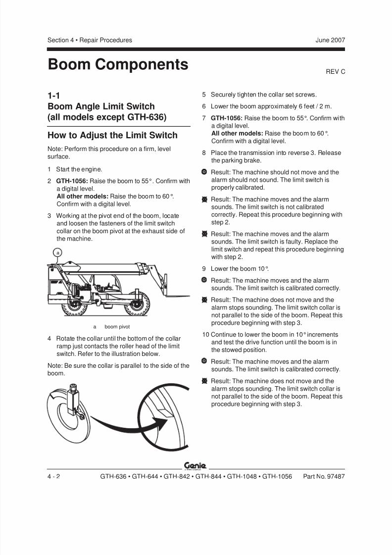
8/14/2019 Genie Manual de Servicio Gth-844
http://slidepdf.com/reader/full/genie-manual-de-servicio-gth-844 72/196
REV C
Section 4 • Repair Procedures June 2007
4 - 2 GTH-636 • GTH-644 • GTH-842 • GTH-844 • GTH-1048 • GTH-1056 Part No. 97487
1-1Boom Angle Limit Switch(all models except GTH-636)
How to Adjust the Limit Switch
Note: Perform this procedure on a firm, levelsurface.
1 Start the engine.
2 GTH-1056: Raise the boom to 55°. Confirm with
a digital level.
All other models: Raise the boom to 60°.Confirm with a digital level.
3 Working at the pivot end of the boom, locateand loosen the fasteners of the limit switch
collar on the boom pivot at the exhaust side ofthe machine.
5 Securely tighten the collar set screws.6 Lower the boom approximately 6 feet / 2 m.
7 GTH-1056: Raise the boom to 55°. Confirm witha digital level.All other models: Raise the boom to 60°.
Confirm with a digital level.
8 Place the transmission into reverse 3. Releasethe parking brake.
Result: The machine should not move and thealarm should not sound. The limit switch isproperly calibrated.
Result: The machine moves and the alarmsounds. The limit switch is not calibratedcorrectly. Repeat this procedure beginning with
step 2.
Result: The machine moves and the alarmsounds. The limit switch is faulty. Replace the
limit switch and repeat this procedure beginningwith step 2.
9 Lower the boom 10°.
Result: The machine moves and the alarmsounds. The limit switch is calibrated correctly.
Result: The machine does not move and the
alarm stops sounding. The limit switch collar isnot parallel to the side of the boom. Repeat this
procedure beginning with step 3.
10 Continue to lower the boom in 10° incrementsand test the drive function until the boom is in
the stowed position.
Result: The machine moves and the alarmsounds. The limit switch is calibrated correctly.
Result: The machine does not move and the
alarm stops sounding. The limit switch collar isnot parallel to the side of the boom. Repeat this
procedure beginning with step 3.
Boom Components
a boom pivot
4 Rotate the collar until the bottom of the collarramp just contacts the roller head of the limit
switch. Refer to the illustration below.
Note: Be sure the collar is parallel to the side of theboom.
a
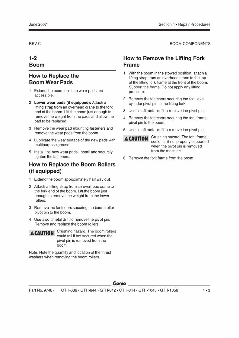
8/14/2019 Genie Manual de Servicio Gth-844
http://slidepdf.com/reader/full/genie-manual-de-servicio-gth-844 73/196
REV C
Section 4 • Repair ProceduresJune 2007
Part No. 97487 GTH-636 • GTH-644 • GTH-842 • GTH-844 • GTH-1048 • GTH-1056 4 - 3
BOOM COMPONENTS
1-2Boom
How to Replace theBoom Wear Pads
1 Extend the boom until the wear pads areaccessible.
2 Lower wear pads (if equipped): Attach a
lifting strap from an overhead crane to the forkend of the boom. Lift the boom just enough to
remove the weight from the pads and allow thepad to be replaced.
3 Remove the wear pad mounting fasteners and
remove the wear pads from the boom.
4 Lubricate the wear surface of the new pads withmultipurpose grease.
5 Install the new wear pads. Install and securelytighten the fasteners.
How to Replace the Boom Rollers(if equipped)
1 Extend the boom approximately half way out.
2 Attach a lifting strap from an overhead crane tothe fork end of the boom. Lift the boom just
enough to remove the weight from the lowerrollers.
3 Remove the fasteners securing the boom roller
pivot pin to the boom.
4 Use a soft metal drift to remove the pivot pin.Remove and replace the boom rollers.
Crushing hazard. The boom rollers
could fall if not secured when thepivot pin is removed from the
boom.
Note: Note the quantity and location of the thrustwashers when removing the boom rollers.
How to Remove the Lifting ForkFrame
1 With the boom in the stowed position, attach alifting strap from an overhead crane to the topof the lifting fork frame at the front of the boom.
Support the frame. Do not apply any liftingpressure.
2 Remove the fasteners securing the fork level
cylinder pivot pin to the lifting fork.
3 Use a soft metal drift to remove the pivot pin.
4 Remove the fasteners securing the fork framepivot pin to the boom.
5 Use a soft metal drift to remove the pivot pin.
Crushing hazard. The fork framecould fall if not properly supported
when the pivot pin is removedfrom the machine.
6 Remove the fork frame from the boom.
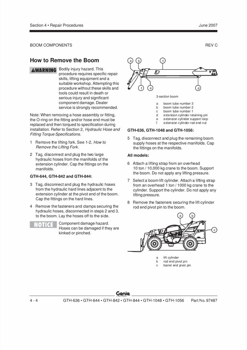
8/14/2019 Genie Manual de Servicio Gth-844
http://slidepdf.com/reader/full/genie-manual-de-servicio-gth-844 74/196
REV C
Section 4 • Repair Procedures June 2007
4 - 4 GTH-636 • GTH-644 • GTH-842 • GTH-844 • GTH-1048 • GTH-1056 Part No. 97487
BOOM COMPONENTS
cba
df e
How to Remove the BoomBodily injury hazard. Thisprocedure requires specific repair
skills, lifting equipment and asuitable workshop. Attempting thisprocedure without these skills and
tools could result in death orserious injury and significant
component damage. Dealerservice is strongly recommended.
Note: When removing a hose assembly or fitting,
the O-ring on the fitting and/or hose end must bereplaced and then torqued to specification during
installation. Refer to Section 2, Hydraulic Hose and Fitting Torque Specifications.
1 Remove the lifting fork. See 1-2, How to Remove the Lifting Fork .
2 Tag, disconnect and plug the two large
hydraulic hoses from the manifolds of theextension cylinder. Cap the fittings on the
manifolds.
GTH-644, GTH-842 and GTH-844:
3 Tag, disconnect and plug the hydraulic hosesfrom the hydraulic hard lines adjacent to theextension cylinder at the pivot end of the boom.
Cap the fittings on the hard lines.
4 Remove the fasteners and clamps securing thehydraulic hoses, disconnected in steps 2 and 3,
to the boom. Lay the hoses off to the side.
Component damage hazard.
Hoses can be damaged if they arekinked or pinched.
3-section boom
a boom tube number 3b boom tube number 2c boom tube number 1d extension cylinder retaining pine extension cylinder support loop
f extension cylinder rod end nut
GTH-636, GTH-1048 and GTH-1056:
5 Tag, disconnect and plug the remaining boom
supply hoses at the respective manifolds. Capthe fittings on the manifolds.
All models:
6 Attach a lifting strap from an overhead10 ton / 10,000 kg crane to the boom. Support
the boom. Do not apply any lifting pressure.
7 Select a boom lift cylinder. Attach a lifting strap
from an overhead 1 ton / 1000 kg crane to thecylinder. Support the cylinder. Do not apply anylifting pressure.
8 Remove the fasteners securing the lift cylinderrod end pivot pin to the boom.
ba
c
a lift cylinderb rod end pivot pinc barrel end pivot pin
8/14/2019 Genie Manual de Servicio Gth-844
http://slidepdf.com/reader/full/genie-manual-de-servicio-gth-844 75/196
REV C
Section 4 • Repair ProceduresJune 2007
Part No. 97487 GTH-636 • GTH-644 • GTH-842 • GTH-844 • GTH-1048 • GTH-1056 4 - 5
BOOM COMPONENTS
9 Use a soft metal drift to remove the rod endpivot pin from the cylinder.
Crushing hazard. The boom willfall if not properly supported when
the lift cylinder pivot pin isremoved from the machine.
Crushing hazard. The cylinder will
fall if not properly supported whenthe pivot pin is removed.
10 Using the crane, raise the cylinder slightly.
11 Place a block measuring
3 x 3 x 3 inches / 7 x 7 x 7 cm between thecylinder manifold and the chassis.
12 Lower the cylinder until the cylinder manifold
rests on the block.
Crushing hazard. Keep handsclear of the cylinder manifold when
lowering the cylinder.
13 Repeat this procedure, beginning with step 7,
for the other lift cylinder.
14 Using the crane, raise the boom to a horizontalposition.
15 Remove the fasteners securing the boom pivot
pin to the machine.
16 Use a soft metal drift to remove the pivot pin.Crushing hazard. The boom will
fall if not properly supported whenthe pivot pin is removed from the
machine.
17 Carefully remove the boom assembly from themachine and place it on a structure capable of
supporting it.
Crushing hazard. The boom couldbecome unbalanced and fall if not
properly supported when removedfrom the machine.
Component damage hazard. The
weight of the boom assembly maycrush the hydraulic hard lines
under the boom. Use cautionwhen placing the boom assembly
onto a structure capable ofsupporting it.
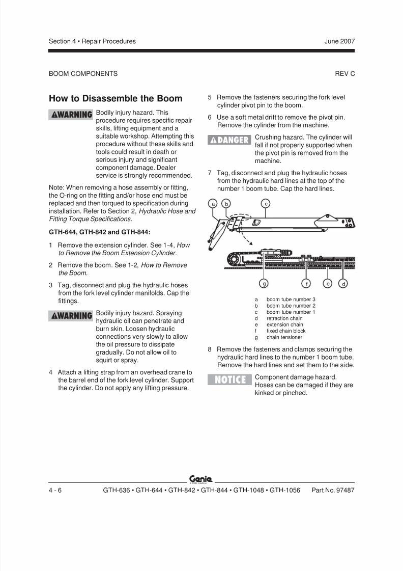
8/14/2019 Genie Manual de Servicio Gth-844
http://slidepdf.com/reader/full/genie-manual-de-servicio-gth-844 76/196
REV C
Section 4 • Repair Procedures June 2007
4 - 6 GTH-636 • GTH-644 • GTH-842 • GTH-844 • GTH-1048 • GTH-1056 Part No. 97487
How to Disassemble the BoomBodily injury hazard. Thisprocedure requires specific repair
skills, lifting equipment and asuitable workshop. Attempting thisprocedure without these skills and
tools could result in death orserious injury and significant
component damage. Dealerservice is strongly recommended.
Note: When removing a hose assembly or fitting,
the O-ring on the fitting and/or hose end must bereplaced and then torqued to specification during
installation. Refer to Section 2, Hydraulic Hose and Fitting Torque Specifications.
GTH-644, GTH-842 and GTH-844:
1 Remove the extension cylinder. See 1-4, How to Remove the Boom Extension Cylinder .
2 Remove the boom. See 1-2, How to Remove
the Boom .
3 Tag, disconnect and plug the hydraulic hosesfrom the fork level cylinder manifolds. Cap the
fittings.
Bodily injury hazard. Sprayinghydraulic oil can penetrate and
burn skin. Loosen hydraulicconnections very slowly to allowthe oil pressure to dissipate
gradually. Do not allow oil tosquirt or spray.
4 Attach a lifting strap from an overhead crane tothe barrel end of the fork level cylinder. Supportthe cylinder. Do not apply any lifting pressure.
cba
dfg e
BOOM COMPONENTS
5 Remove the fasteners securing the fork levelcylinder pivot pin to the boom.
6 Use a soft metal drift to remove the pivot pin.Remove the cylinder from the machine.
Crushing hazard. The cylinder will
fall if not properly supported whenthe pivot pin is removed from the
machine.
7 Tag, disconnect and plug the hydraulic hosesfrom the hydraulic hard lines at the top of the
number 1 boom tube. Cap the hard lines.
a boom tube number 3b boom tube number 2c boom tube number 1d retraction chaine extension chainf fixed chain blockg chain tensioner
8 Remove the fasteners and clamps securing the
hydraulic hard lines to the number 1 boom tube.Remove the hard lines and set them to the side.
Component damage hazard.
Hoses can be damaged if they arekinked or pinched.

8/14/2019 Genie Manual de Servicio Gth-844
http://slidepdf.com/reader/full/genie-manual-de-servicio-gth-844 77/196
REV C
Section 4 • Repair ProceduresJune 2007
Part No. 97487 GTH-636 • GTH-644 • GTH-842 • GTH-844 • GTH-1048 • GTH-1056 4 - 7
16 Using the crane, raise the front end of thenumbers 2 and 3 boom tube assembly slightlyand remove the bottom wear pads of thenumber 1 boom tube.
17 Support and slide the numbers 2 and 3 boomtube assembly out of the number 1 boom tube.
Place the numbers 2 and 3 boom tubeassembly on a structure capable of supportingit.
Crushing hazard. The numbers 2and 3 boom tube assembly maybecome unbalanced and fall when
removed from the number 1 boomtube if not properly supported and
attached to the overhead crane.
Note: During removal, the overhead crane strapwill need to be adjusted for proper balancing.
18 Remove the fork level cylinder hydraulic hosesfrom the boom assembly.
19 Remove the fasteners securing the extensionchain pivot pin to the number 3 boom tube.
20 Use a soft metal drift to remove the pivot pin.
Remove the chain and set it to the side.Note: Do not allow the chain to become twisted ordirty.
21 Extend the number 3 boom tube enough toaccess the inner wear pads of the number 2
boom tube.
22 Remove the top and side wear pads of thenumber 2 boom tube at the fork end of the
boom.
BOOM COMPONENTS
9 Remove the fasteners securing the chaintensioner of the number 3 extension chain tothe number 1 boom tube.
10 Remove the fasteners securing the fixed chain
block of the number 3 retraction chain to thenumber 1 boom tube.
Note: The fixed chain block of the number 3
retraction chain is secured to the inside of thenumber 1 boom tube and is hidden from view when
installed.
11 Extend the number 2 boom tube assembly
enough to access the inner wear pads of thenumber 1 boom tube.
12 Remove the top and side wear pads of the
number 1 boom tube at the fork end of theboom.
13 Using a chain of sufficient capacity, secure
together the numbers 2 and 3 boom tubes.
14 Attach a lifting strap from an overhead crane tothe numbers 2 and 3 boom tube assembly at
the fork end of the boom.
15 Support and slide the numbers 2 and 3 boom
tube assembly approximately halfway out of thenumber 1 boom tube.
Crushing hazard. The boomassembly may become
unbalanced and fall when thenumbers 2 and 3 boom tubes are
moved if not secured together.

8/14/2019 Genie Manual de Servicio Gth-844
http://slidepdf.com/reader/full/genie-manual-de-servicio-gth-844 78/196
REV C
Section 4 • Repair Procedures June 2007
4 - 8 GTH-636 • GTH-644 • GTH-842 • GTH-844 • GTH-1048 • GTH-1056 Part No. 97487
23 Support and slide the number 3 boom tubeassembly approximately halfway out of thenumber 2 boom tube.
24 Using the crane, raise the fork end of the
number 3 boom tube assembly slightly andremove the bottom wear pads of the number 2
boom tube.
25 Support and slide the number 3 boom tubeassembly out of the number 2 boom tube.
Place the number 3 boom tube assembly on astructure capable of supporting it.
Crushing hazard. The number 3
boom tube could becomeunbalanced and fall whenremoved from the number 2 boom
tube if not properly supported andattached to the overhead crane.
Note: During removal, the overhead crane strapwill need to be adjusted for proper balancing.
BOOM COMPONENTS
GTH-636 and GTH-1048:1 Remove the extension cylinder. See 1-4, How
to Remove the Boom Extension Cylinder .
2 Remove the boom. See 1-2, How to Remove
the Boom .
3 Remove the access cover from the fork of the
boom. Remove the clamp securing thehydraulic hoses to the top of the gooseneck atthe fork end of the boom (if equipped).
4 Attach a lifting strap from an overhead crane tothe rod end of the fork level cylinder.
5 Raise the cylinder enough to access the
manifolds of the fork level cylinder.
6 Tag, disconnect and plug the hydraulic hosesfrom the fork level cylinder manifolds. Cap the
fittings. Lower the cylinder.
Bodily injury hazard. Sprayinghydraulic oil can penetrate and
burn skin. Loosen hydraulicconnections very slowly to allow
the oil pressure to dissipategradually. Do not allow oil to
squirt or spray.
Crushing hazard. Keep handsclear of the cylinder whenlowering.
Component damage hazard.Hoses can be damaged if they arekinked or pinched.
7 Attach a lifting strap from an overhead crane tothe barrel end of the fork level cylinder.
8 Remove the fasteners securing the fork level
cylinder barrel-end pivot pin to the boom.
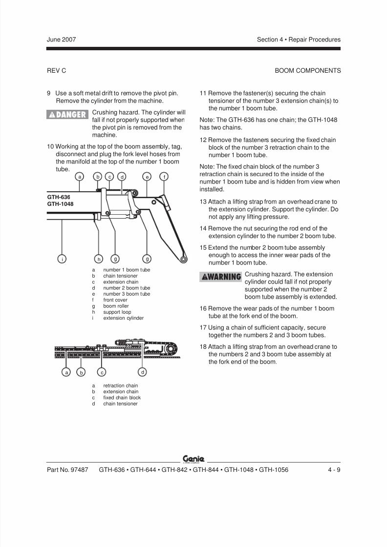
8/14/2019 Genie Manual de Servicio Gth-844
http://slidepdf.com/reader/full/genie-manual-de-servicio-gth-844 79/196
REV C
Section 4 • Repair ProceduresJune 2007
Part No. 97487 GTH-636 • GTH-644 • GTH-842 • GTH-844 • GTH-1048 • GTH-1056 4 - 9
9 Use a soft metal drift to remove the pivot pin.Remove the cylinder from the machine.
Crushing hazard. The cylinder willfall if not properly supported when
the pivot pin is removed from themachine.
10 Working at the top of the boom assembly, tag,
disconnect and plug the fork level hoses fromthe manifold at the top of the number 1 boom
tube.
11 Remove the fastener(s) securing the chaintensioner of the number 3 extension chain(s) tothe number 1 boom tube.
Note: The GTH-636 has one chain; the GTH-1048
has two chains.
12 Remove the fasteners securing the fixed chain
block of the number 3 retraction chain to thenumber 1 boom tube.
Note: The fixed chain block of the number 3
retraction chain is secured to the inside of thenumber 1 boom tube and is hidden from view when
installed.13 Attach a lifting strap from an overhead crane to
the extension cylinder. Support the cylinder. Donot apply any lifting pressure.
14 Remove the nut securing the rod end of the
extension cylinder to the number 2 boom tube.
15 Extend the number 2 boom tube assemblyenough to access the inner wear pads of the
number 1 boom tube.
Crushing hazard. The extensioncylinder could fall if not properly
supported when the number 2boom tube assembly is extended.
16 Remove the wear pads of the number 1 boomtube at the fork end of the boom.
17 Using a chain of sufficient capacity, secure
together the numbers 2 and 3 boom tubes.
18 Attach a lifting strap from an overhead crane tothe numbers 2 and 3 boom tube assembly at
the fork end of the boom.
a db c
GTH-636
GTH-1048
a
i gh
cb d e f
g
a number 1 boom tubeb chain tensionerc extension chain
d number 2 boom tubee number 3 boom tubef front coverg boom rollerh support loopi extension cylinder
a retraction chainb extension chainc fixed chain blockd chain tensioner
BOOM COMPONENTS
8/14/2019 Genie Manual de Servicio Gth-844
http://slidepdf.com/reader/full/genie-manual-de-servicio-gth-844 80/196
REV C
Section 4 • Repair Procedures June 2007
4 - 10 GTH-636 • GTH-644 • GTH-842 • GTH-844 • GTH-1048 • GTH-1056 Part No. 97487
19 Support and slide the numbers 2 and 3 boomtube assembly approximately halfway out of thenumber 1 boom tube.
Crushing hazard. The boom
assembly could becomeunbalanced and fall when the
numbers 2 and 3 boom tubes aremoved if not secured together.
20 If equipped, remove the fasteners securing the
side wear pads to the number 1 boom tube, andremove the wear pads.
21 Raise the front end of the numbers 2 and 3
boom tube assembly slightly and remove theboom rollers from the number 1 boom tube.
22 Support and slide the numbers 2 and 3 boom
tube assembly out of the number 1 boom tube.Place the numbers 2 and 3 boom tube
assembly on a structure capable of supportingit.
Crushing hazard. The numbers 2
and 3 boom tube assembly couldbecome unbalanced and fall whenremoved from the number 1 boom
tube if not properly supported andattached to the overhead crane.
Note: During removal, the overhead crane strap
will need to be adjusted for proper balancing.
23 Remove the fasteners securing the extensionchain pivot pin to the number 3 boom tube.
24 Use a soft metal drift to remove the pivot pin.
Remove the chain and set it to the side.
Note: Do not allow the chain to become twisted ordirty.
25 Extend the number 3 boom tube assemblyenough to access the inner wear pads of thenumber 2 boom tube.
26 Remove the wear pads of the number 2 boom
tube at the front end of the boom.
27 Attach a lifting strap from an overhead crane tothe number 3 boom tube assembly at the fork
end of the boom.
28 Support and slide the number 3 boom tubeassembly approximately halfway out of the
number 2 boom tube.
29 If equipped, remove the fasteners securing theside wear pads to the number 2 boom tube, and
remove the wear pads.
30 Raise the front end of the number 3 boom tubeassembly slightly and remove the boom rollers
of the number 2 boom tube.
31 Support and slide the number 3 boom tubeassembly out of the number 2 boom tube.
Place the number 3 boom tube assembly on astructure capable of supporting it.
Crushing hazard. The number 3
boom tube assembly couldbecome unbalanced and fall when
removed from the number 2 boomtube if not properly supported and
attached to the overhead crane.
Note: During removal, the overhead crane strapwill need to be adjusted for proper balancing.
BOOM COMPONENTS
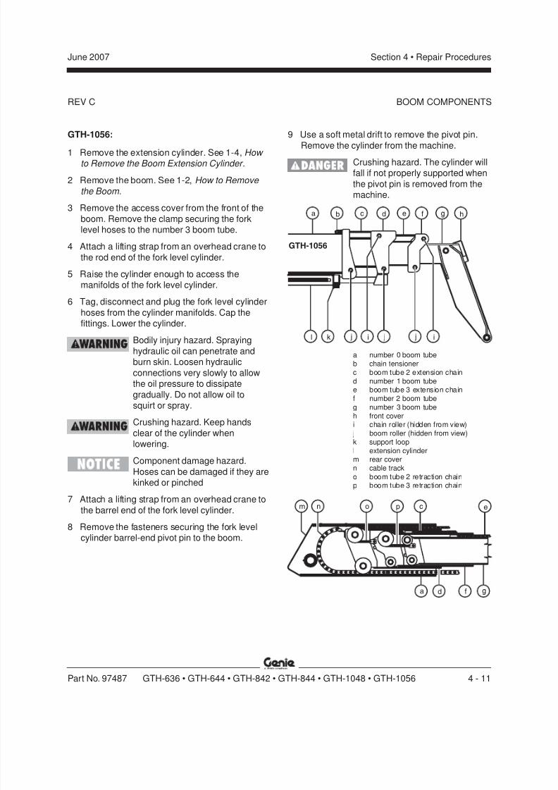
8/14/2019 Genie Manual de Servicio Gth-844
http://slidepdf.com/reader/full/genie-manual-de-servicio-gth-844 81/196
REV C
Section 4 • Repair ProceduresJune 2007
Part No. 97487 GTH-636 • GTH-644 • GTH-842 • GTH-844 • GTH-1048 • GTH-1056 4 - 11
GTH-1056:1 Remove the extension cylinder. See 1-4, How
to Remove the Boom Extension Cylinder .
2 Remove the boom. See 1-2, How to Remove
the Boom .
3 Remove the access cover from the front of the
boom. Remove the clamp securing the forklevel hoses to the number 3 boom tube.
4 Attach a lifting strap from an overhead crane to
the rod end of the fork level cylinder.
5 Raise the cylinder enough to access themanifolds of the fork level cylinder.
6 Tag, disconnect and plug the fork level cylinder
hoses from the cylinder manifolds. Cap thefittings. Lower the cylinder.
Bodily injury hazard. Spraying
hydraulic oil can penetrate andburn skin. Loosen hydraulic
connections very slowly to allowthe oil pressure to dissipate
gradually. Do not allow oil tosquirt or spray.
Crushing hazard. Keep hands
clear of the cylinder whenlowering.
Component damage hazard.
Hoses can be damaged if they arekinked or pinched
7 Attach a lifting strap from an overhead crane to
the barrel end of the fork level cylinder.
8 Remove the fasteners securing the fork levelcylinder barrel-end pivot pin to the boom.
9 Use a soft metal drift to remove the pivot pin.Remove the cylinder from the machine.
Crushing hazard. The cylinder willfall if not properly supported when
the pivot pin is removed from themachine.
gc he
l k
GTH-1056
fda b
j ji j i
en co p
a f g
m
d
a number 0 boom tubeb chain tensionerc boom tube 2 extension chaind number 1 boom tubee boom tube 3 extension chainf number 2 boom tubeg number 3 boom tube
h front coveri chain roller (hidden from view) j boom roller (hidden from view)k support loopl extension cylinderm rear covern cable tracko boom tube 2 retraction chainp boom tube 3 retraction chain
BOOM COMPONENTS
8/14/2019 Genie Manual de Servicio Gth-844
http://slidepdf.com/reader/full/genie-manual-de-servicio-gth-844 82/196
REV C
Section 4 • Repair Procedures June 2007
4 - 12 GTH-636 • GTH-644 • GTH-842 • GTH-844 • GTH-1048 • GTH-1056 Part No. 97487
10 Attach a lifting strap from an overhead crane tothe extension cylinder. Support the cylinder. Donot apply any lifting pressure.
11 Remove the nut securing the rod end of the
extension cylinder to the number 1 boom tube.
12 Extend the number 1 boom tube until the hosemanifolds are accessible.
Crushing hazard. The boom
assembly could fall when thenumber 1 boom tube is extended if
not properly supported andattached to the overhead crane.
13 Tag, disconnect and plug the hydraulic hoses at
the top of the hose manifolds at the top of thenumber 1 boom tube. Cap the fittings.
Component damage hazard.
Hoses can be damaged if they arekinked or pinched.
Note: Do not remove the hose manifolds at this
time.
14 Remove the wear pads of the number 0 boomtube at the front end of the boom.
15 Manually return the boom tubes to the stowed
position.
16 Remove the access cover from the rear of theboom.
17 Working with a screwdriver inside the rear of
the boom, carefully remove eight of the externalhinge link tabs from the end of the cable track
where it attaches to the number 3 boom tube.
18 Using a screwdriver, carefully separate thecable track from the cable track mount at the
rear of the number 3 boom tube.
19 Loosen evenly, then remove, the fastenerssecuring the chain tensioners of the boom tube2 extension chains to the number 0 boom tube.
20 Remove the fasteners securing the fixed chain
block of the boom tube 2 retraction chain to thetop of the number 0 boom tube near the front of
the tube.
Note: The fixed chain block of the boom tube 2retraction chain is secured to the inside of the
number 0 boom tube and is hidden from view wheninstalled.
21 Using a chain of sufficient capacity, securetogether the numbers 1, 2 and 3 boom tubes.
Note:To secure the boom tubes together, it may be
helpful to loosen the boom roller fasteners at oneside of the boom, wrapping the chain around the
boom roller pin between the nut and the side of theboom.
22 Attach a lifting strap from an overhead crane tothe numbers 1, 2 and 3 boom tube assemblies
at the fork end of the boom.
23 Support and slide the numbers 1, 2 and 3 boom
tube assemblies approximately halfway out ofthe number 0 boom tube.
Crushing hazard. The boomassembly could become
unbalanced and fall when thenumbers 1, 2 and 3 boom tubes
are moved if not secured together.
24 If equipped, remove the fasteners securing theside wear pads to the number 0 boom tube, and
remove the wear pads.
BOOM COMPONENTS
8/14/2019 Genie Manual de Servicio Gth-844
http://slidepdf.com/reader/full/genie-manual-de-servicio-gth-844 83/196
REV C
Section 4 • Repair ProceduresJune 2007
Part No. 97487 GTH-636 • GTH-644 • GTH-842 • GTH-844 • GTH-1048 • GTH-1056 4 - 13
25 Raise the fork end of the number 1 boom tubeassembly slightly and remove the boom rollersfrom the number 0 boom tube.
26 Support and slide the numbers 1, 2 and 3 boom
tube assemblies out of the number 0 boomtube. Place the numbers 1, 2 and 3 boom tube
assemblies on a structure capable ofsupporting it.
Crushing hazard. The numbers 1,
2 and 3 boom tube assembliescould become unbalanced and fallwhen removed from the number 0
boom tube if not properlysupported and attached to the
overhead crane.
Note: During removal, the overhead crane strapwill need to be adjusted for proper balancing.
27 Remove the chain tensioner from the end ofboth number 2 boom tube extension chains.
28 Remove the cable track mount bracket from therear of the number 1 boom tube.
29 Remove the chain or device securing the
booms together.30 Evenly remove the fasteners securing the chain
tensioners of the boom tube 3 extension chains
to the number 1 boom tube.
31 Remove the fasteners securing the fixed chainblock of the number 3 boom tube retraction
chain to the top of the number 1 boom tubenear the fork end of the tube.
Note: The fixed chain block of the number 3 boom
tube retraction chain is secured to the inside of thenumber 1 boom tube and is hidden from view when
installed.
32 Remove the hose manifolds from the top of thenumber 1 boom tube. Tag, disconnect and plugthe hoses from the hose manifolds. Cap thefittings.
Component damage hazard.Hoses can be damaged if they are
kinked or pinched.
33 Remove the fork level cylinder hoses from theboom assembly.
34 Extend the number 2 boom tube approximately
12 inches / 30 cm.
35 Remove the chain rollers from the top of thenumber 1 boom tube at the front of the boom.
36 Remove the wear pads of the number 1 boom
tube at the front end of the boom.
37 Manually return the boom tubes to the stowedposition.
38 Using a chain of sufficient capacity, securetogether the numbers 2 and 3 boom tubes.
39 Attach a lifting strap from an overhead crane to
the numbers 2 and 3 boom tube assemblies atthe fork end of the boom.
40 Support and slide the numbers 2 and 3 boom
tube assemblies approximately halfway out ofthe number 1 boom tube.
Crushing hazard. The boom
assembly could becomeunbalanced and fall when the
numbers 2 and 3 boom tubes aremoved if not secured together.
BOOM COMPONENTS
8/14/2019 Genie Manual de Servicio Gth-844
http://slidepdf.com/reader/full/genie-manual-de-servicio-gth-844 84/196
REV C
Section 4 • Repair Procedures June 2007
4 - 14 GTH-636 • GTH-644 • GTH-842 • GTH-844 • GTH-1048 • GTH-1056 Part No. 97487
41 If equipped, remove the fasteners securing theside wear pads to the number 1 boom tube, andremove the wear pads.
42 Raise the fork end of the number 2 boom tube
assembly slightly and remove the boom rollersfrom the number 1 boom tube.
43 Support and slide the numbers 2 and 3 boom
tube assemblies out of the number 1 boomtube. Place the numbers 2 and 3 boom tube
assemblies on a structure capable ofsupporting it.
Crushing hazard. The numbers 2
and 3 boom tube assembliescould become unbalanced and fallwhen removed from the number 1
boom tube if not properlysupported and attached to the
overhead crane.
Note: During removal, the overhead crane strapwill need to be adjusted for proper balancing.
44 Remove the chain or device securing thebooms together.
45 Extend the number 3 boom tube approximately12 inches / 30 cm.
46 Remove the chain rollers from the top of the
number 2 boom tube at the fork end of theboom.
47 Remove the wear pads of the number 2 boom
tube at the fork end of the boom.
48 Attach a lifting strap from an overhead crane tothe number 3 boom tube assembly at the fork
end of the boom.
49 Support and slide the number 3 boom tubeassembly approximately halfway out of thenumber 2 boom tube.
50 If equipped, remove the fasteners securing the
side wear pads to the number 2 boom tube, andremove the wear pads.
51 Raise the fork end of the number 3 boom tube
assembly slightly and remove the boom rollersof the number 2 boom tube.
52 Support and slide the number 3 boom tube
assembly out of the number 2 boom tube.Place the number 3 boom tube assembly on a
structure capable of supporting it.
Crushing hazard. The number 3boom tube assembly could
become unbalanced and fall whenremoved from the number 2 boom
tube if not properly supported andattached to the overhead crane.
Note: During removal, the overhead crane strap
will need to be adjusted for proper balancing.
BOOM COMPONENTS
8/14/2019 Genie Manual de Servicio Gth-844
http://slidepdf.com/reader/full/genie-manual-de-servicio-gth-844 85/196
REV C
Section 4 • Repair ProceduresJune 2007
Part No. 97487 GTH-636 • GTH-644 • GTH-842 • GTH-844 • GTH-1048 • GTH-1056 4 - 15
1-3Boom Lift Cylinder
How to Remove a Lift Cylinder
Note: When removing a hose assembly or fitting,
the O-ring on the fitting and/or hose end must bereplaced and then torqued to specification duringinstallation. Refer to Section 2, Hydraulic Hose and
Fitting Torque Specifications.
1 Attach an overhead 10 ton / 10,000 kg crane tothe boom. Support the boom. Do not apply any
lifting pressure.
2 Tag, disconnect and plug the two largerhydraulic hoses at the lift cylinder and manifold.Cap the fittings.
Bodily injury hazard. Sprayinghydraulic oil can penetrate andburn skin. Loosen hydraulic
connections very slowly to allowthe oil pressure to dissipate
gradually. Do not allow oil tosquirt or spray.
Component damage hazard.Hoses can be damaged if they arekinked or pinched.
3 Remove the fasteners securing the lift cylinder
pivot pin to the chassis.
BOOM COMPONENTS
4 Use a soft metal drift to remove the pivot pin.Crushing hazard. The boom will
fall if not properly supported whenthe pivot pin is removed from the
machine.
5 Using the overhead crane, raise the boom to ahorizontal position.
6 Attach a lifting strap from an overhead crane to
the lift cylinder. Support the cylinder. Do notapply any lifting pressure.
7 Remove the fasteners securing the lift cylinder
collar to the boom. Remove the collar.
8 Remove the cylinder from the machine.
Crushing hazard. The cylinder will
fall if not properly supported whenremoved from the machine.
8/14/2019 Genie Manual de Servicio Gth-844
http://slidepdf.com/reader/full/genie-manual-de-servicio-gth-844 86/196
REV C
Section 4 • Repair Procedures June 2007
4 - 16 GTH-636 • GTH-644 • GTH-842 • GTH-844 • GTH-1048 • GTH-1056 Part No. 97487
How to Bleed the Lift/Tilt Circuit1 With the machine on a firm, level surface, start
the engine and allow the engine to idle.
2 Raise the boom to full height, then lower the
boom to the stowed position.
3 Repeat step 2.
4 Raise the tips of the lifting forks to full height,
then continue to activate the fork tilt up functionfor a minimum of 60 seconds. Release the
joystick.
5 Stop the engine.
6 Select one of the boom lift cylinders. Locate thebleed fitting at the top of the cylinder.
7 Securely install a clear hose onto the bleeder
fitting. Place the other end of the hose into asuitable container to collect hydraulic fluid.
8 Using a wrench, carefully open the bleeder
fitting on the cylinder and allow the pressurizedfluid to drain through the hose and into the
container. Close the bleeder fitting.
Bodily injury hazard. Sprayinghydraulic oil can penetrate and
burn skin. Loosen hydraulicconnections very slowly to allow
the oil pressure to dissipategradually. Do not allow oil tosquirt or spray.
9 Start the engine and allow the engine to idle.
10 Activate the fork tilt up function forapproximately 15 seconds.
11 Repeat this procedure beginning with step 8
until a steady stream of oil without air bubbles isvisible through the bleeder hose.
12 Repeat this procedure for the other cylinder,
beginning with step 6.
BOOM COMPONENTS

8/14/2019 Genie Manual de Servicio Gth-844
http://slidepdf.com/reader/full/genie-manual-de-servicio-gth-844 87/196
REV C
Section 4 • Repair ProceduresJune 2007
Part No. 97487 GTH-636 • GTH-644 • GTH-842 • GTH-844 • GTH-1048 • GTH-1056 4 - 17
1-4Boom Extension Cylinder
How to Remove theExtension Cylinder
Note: When removing a hose assembly or fitting,the O-ring on the fitting and/or hose end must be
replaced and then torqued to specification duringinstallation. Refer to Section 2, Hydraulic Hose and
Fitting Torque Specifications.
1 Raise the boom to a horizontal position.2 Extend the boom approximately 1 foot / 30 cm.
3 Attach a lifting strap from an overhead crane tothe extension cylinder. Support the cylinder. Do
not apply any lifting pressure.
6 Place a wooden block, which measuresapproximately 2 x 4 x 12 inches / 5 x 10 x 30cm, onto the top of the number 2 boom tube ina way that will prevent the number 2 boom tube
from retracting into the number 1 boom tube.
7 Retract the extension cylinder to the stowed
position. Turn the machine off.
Crushing hazard. The extensioncylinder will fall if not properly
supported when the cylinder isretracted.
8 Tag, disconnect and plug the hydraulic hoses
from the extension cylinder manifolds. Cap thefittings on the manifolds.
Bodily injury hazard. Spraying
hydraulic oil can penetrate andburn skin. Loosen hydraulic
connections very slowly to allowthe oil pressure to dissipategradually. Do not allow oil to
squirt or spray.
Component damage hazard.Hoses can be damaged if they are
kinked or pinched.
9 Remove the fasteners securing the extensioncylinder barrel end pivot pin to the boom.
10 Use a soft metal drift to remove the pivot pin.Remove the cylinder from the machine.
Crushing hazard. The extension
cylinder will fall if not properlysupported when the pivot pin isremoved from the machine.
BOOM COMPONENTS
a boom tube number 3b boom tube number 2c boom tube number 1d extension cylinder retaining pine extension cylinder support loopf extension cylinder rod end nut
4 Remove the nut securing the rod end of theextension cylinder to the number 2 boom tube.
5 Remove the extension cylinder support loopfrom the number 3 boom tube.
cba
df e
8/14/2019 Genie Manual de Servicio Gth-844
http://slidepdf.com/reader/full/genie-manual-de-servicio-gth-844 88/196
REV C
Section 4 • Repair Procedures June 2007
4 - 18 GTH-636 • GTH-644 • GTH-842 • GTH-844 • GTH-1048 • GTH-1056 Part No. 97487
1-5Fork Level Cylinder
How to Remove the Fork LevelCylinder
1 With the boom in the stowed position, fully lowerthe tips of the lifting forks.
2 Remove the access cover from the fork of the
boom.
3 Attach a lifting strap from an overhead crane to
the top of the lifting fork frame. Support theframe. Do not apply any lifting pressure.
4 Attach a lifting strap from a second overhead
crane to the barrel end of the fork level cylinder.Support the cylinder. Do not apply any liftingpressure.
5 Tag, disconnect and plug the fork level cylinderhoses from the cylinder manifolds. Cap thefittings.
Bodily injury hazard. Sprayinghydraulic oil can penetrate and
burn skin. Loosen hydraulicconnections very slowly to allowthe oil pressure to dissipate
gradually. Do not allow oil tosquirt or spray.
Component damage hazard.
Hoses can be damaged if they arekinked or pinched
6 Remove the fasteners securing the fork levelcylinder rod-end pivot pin to the boom.
7 Use a soft metal drift to remove the pivot pin.
Crushing hazard. The lifting forkframe could fall if not properly
supported when the pivot pin isremoved from the machine.
8 Remove the fasteners securing the fork level
cylinder barrel-end pivot pin to the boom.
9 Use a soft metal drift to remove the pivot pin.Remove the cylinder from the machine.
Crushing hazard. The cylindercould fall if not properly supportedwhen the pivot pin is removed
from the machine.
BOOM COMPONENTS
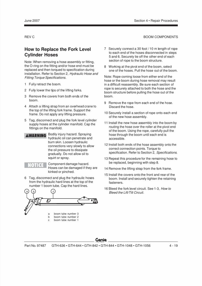
8/14/2019 Genie Manual de Servicio Gth-844
http://slidepdf.com/reader/full/genie-manual-de-servicio-gth-844 89/196
REV C
Section 4 • Repair ProceduresJune 2007
Part No. 97487 GTH-636 • GTH-644 • GTH-842 • GTH-844 • GTH-1048 • GTH-1056 4 - 19
How to Replace the Fork LevelCylinder Hoses
Note: When removing a hose assembly or fitting,the O-ring on the fitting and/or hose end must bereplaced and then torqued to specification during
installation. Refer to Section 2, Hydraulic Hose and Fitting Torque Specifications.
1 Fully retract the boom.
2 Fully lower the tips of the lifting forks.
3 Remove the covers from both ends of the
boom.
4 Attach a lifting strap from an overhead crane tothe top of the lifting fork frame. Support the
frame. Do not apply any lifting pressure.
5 Tag, disconnect and plug the fork level cylindersupply hoses at the cylinder manifold. Cap the
fittings on the manifold.
Bodily injury hazard. Sprayinghydraulic oil can penetrate and
burn skin. Loosen hydraulicconnections very slowly to allow
the oil pressure to dissipategradually. Do not allow oil to
squirt or spray.
Component damage hazard.Hoses can be damaged if they are
kinked or pinched.
6 Tag, disconnect and plug the hydraulic hosesfrom the hydraulic hard lines at the top of the
number 1 boom tube. Cap the hard lines.
7 Securely connect a 30 foot / 10 m length of ropeto each end of the hoses disconnected in steps5 and 6. Securely tie off the other end of eachsection of rope to the boom structure.
8 Working at the pivot end of the boom, selectone of the hoses. Pull the hose out of the boom.
Note: Rope coming loose from either end of the
hose or the boom during hose removal may resultin a difficult reassembly. Be sure each section of
rope is securely attached to both the hose and theboom structure before pulling the hose out of theboom.
9 Remove the rope from each end of the hose.
Discard the hose.
10 Securely install a section of rope onto each endof the new hose assembly.
11 Install the new hose assembly into the boom by
routing the hose over the roller at the pivot endof the boom. Using the rope, carefully pull the
hose through the boom until each end isaccessible.
12 Install both ends of the hose assembly onto the
correct connection points. Torque tospecification. Refer to Section 2, Specifications .
13 Repeat this procedure for the remaining hose to
be replaced, beginning with step 8.
14 Remove the lifting strap from the fork frame.
15 Install the covers onto the front and rear of theboom. Install and securely tighten the retaining
fasteners.
16 Bleed the fork level circuit. See 1-3, How to Bleed the Lift/Tilt Circuit .
BOOM COMPONENTS
cba
a boom tube number 3b boom tube number 2c boom tube number 1
8/14/2019 Genie Manual de Servicio Gth-844
http://slidepdf.com/reader/full/genie-manual-de-servicio-gth-844 90/196
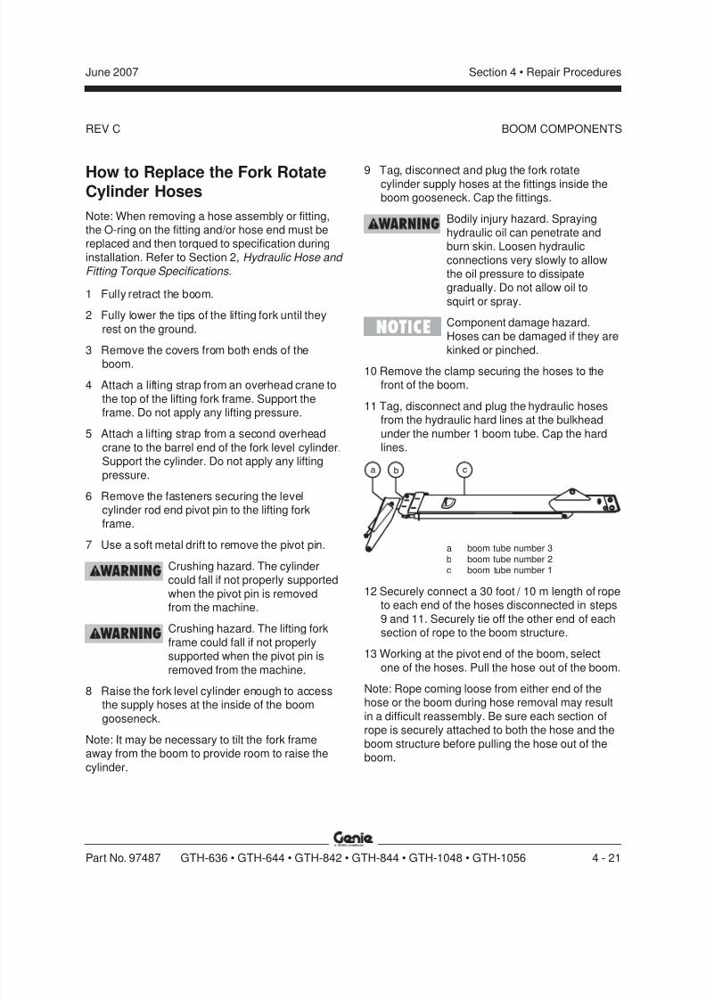
8/14/2019 Genie Manual de Servicio Gth-844
http://slidepdf.com/reader/full/genie-manual-de-servicio-gth-844 91/196
REV C
Section 4 • Repair ProceduresJune 2007
Part No. 97487 GTH-636 • GTH-644 • GTH-842 • GTH-844 • GTH-1048 • GTH-1056 4 - 21
How to Replace the Fork RotateCylinder Hoses
Note: When removing a hose assembly or fitting,the O-ring on the fitting and/or hose end must bereplaced and then torqued to specification during
installation. Refer to Section 2, Hydraulic Hose and Fitting Torque Specifications.
1 Fully retract the boom.
2 Fully lower the tips of the lifting fork until they
rest on the ground.
3 Remove the covers from both ends of theboom.
4 Attach a lifting strap from an overhead crane to
the top of the lifting fork frame. Support theframe. Do not apply any lifting pressure.
5 Attach a lifting strap from a second overhead
crane to the barrel end of the fork level cylinder.Support the cylinder. Do not apply any lifting
pressure.
6 Remove the fasteners securing the levelcylinder rod end pivot pin to the lifting fork
frame.
7 Use a soft metal drift to remove the pivot pin.
Crushing hazard. The cylindercould fall if not properly supported
when the pivot pin is removedfrom the machine.
Crushing hazard. The lifting fork
frame could fall if not properlysupported when the pivot pin is
removed from the machine.
8 Raise the fork level cylinder enough to access
the supply hoses at the inside of the boomgooseneck.
Note: It may be necessary to tilt the fork frameaway from the boom to provide room to raise the
cylinder.
9 Tag, disconnect and plug the fork rotatecylinder supply hoses at the fittings inside theboom gooseneck. Cap the fittings.
Bodily injury hazard. Spraying
hydraulic oil can penetrate andburn skin. Loosen hydraulic
connections very slowly to allowthe oil pressure to dissipategradually. Do not allow oil to
squirt or spray.
Component damage hazard.Hoses can be damaged if they are
kinked or pinched.
10 Remove the clamp securing the hoses to thefront of the boom.
11 Tag, disconnect and plug the hydraulic hosesfrom the hydraulic hard lines at the bulkhead
under the number 1 boom tube. Cap the hardlines.
BOOM COMPONENTS
a boom tube number 3b boom tube number 2c boom tube number 1
12 Securely connect a 30 foot / 10 m length of ropeto each end of the hoses disconnected in steps
9 and 11. Securely tie off the other end of eachsection of rope to the boom structure.
13 Working at the pivot end of the boom, select
one of the hoses. Pull the hose out of the boom.
Note: Rope coming loose from either end of the
hose or the boom during hose removal may resultin a difficult reassembly. Be sure each section ofrope is securely attached to both the hose and the
boom structure before pulling the hose out of theboom.
cba

8/14/2019 Genie Manual de Servicio Gth-844
http://slidepdf.com/reader/full/genie-manual-de-servicio-gth-844 92/196
REV C
Section 4 • Repair Procedures June 2007
4 - 22 GTH-636 • GTH-644 • GTH-842 • GTH-844 • GTH-1048 • GTH-1056 Part No. 97487
14 Remove the rope from each end of the hose.Discard the hose.
15 Securely install a section of rope onto each endof the new hose assembly.
16 Install the new hose assembly into the boom by
routing the hose over the roller at the pivot endof the boom. Using the rope, carefully pull the
hose through the boom until each end isaccessible.
17 Install both ends of the hose assembly onto the
correct connection points. Torque tospecification. Refer to Section 2, Specifications .
18 Repeat this procedure for the remaining hose to
be replaced, beginning with step 13.
19 Install the fork level cylinder. Use a soft metaldrift to install the cylinder pivot pins.
20 Install and securely tighten all pivot pin retaining
fasteners.
21 Remove the lifting strap from the fork frame and
fork level cylinder.
22 Install the covers onto the front and rear of theboom. Install and securely tighten the retaining
fasteners.
Bleed the Fork Rotate Circuit:
23 Start the engine and warm to operating
temperature.
24 Looking from the cab towards the front of theboom, fully rotate the lifting fork frame in a
clockwise direction. Turn the engine off.
25 Disconnect the hydraulic hose with the straight
connector end fitting from the cylinder manifold.
26 Securely install a 24 inch / 60 cm hoseextension into the hose disconnected in step
25. Place the other end of the hose into asuitable container to collect hydraulic fluid.
BOOM COMPONENTS
27 Start the engine and activate the fork rotatecounter clockwise function until a steady streamof oil without air bubbles is flowing from thebleeder hose.
Note: This removes residual air from the barrel endof the cylinder circuit.
28 Looking from the cab towards the front of theboom, fully rotate the lifting fork frame in a
clockwise direction. Turn the engine off.
29 Remove the hose extension from the hose.
30 Install the hose with the straight connector end
fitting onto the cylinder manifold. Torque tospecification. Refer to Section 2, Specifications .
31 Disconnect the hydraulic hose with the 90°connector end fitting from the cylinder manifold.
32 Securely install a 24 inch / 60 cm hoseextension into the hose disconnected in step
31. Place the other end of the hose into acontainer to collect hydraulic fluid.
33 Start the engine and activate the fork rotate
clockwise function until a steady stream of oilwithout air bubbles is flowing from the bleeder
hose.
Note: This removes residual air from the rod end ofthe cylinder circuit.
34 Looking from the cab towards the front of theboom, fully rotate the lifting fork frame in a
counter clockwise direction. Turn the engine off.
35 Remove the hose extension from the hose.
36 Install the hose with the 90° connector endfitting onto the cylinder manifold. Torque to
specification. Refer to Section 2, Specifications .
37 Remove the lifting strap from the fork frame.

8/14/2019 Genie Manual de Servicio Gth-844
http://slidepdf.com/reader/full/genie-manual-de-servicio-gth-844 93/196

8/14/2019 Genie Manual de Servicio Gth-844
http://slidepdf.com/reader/full/genie-manual-de-servicio-gth-844 94/196
REV B
Section 4 • Repair Procedures June 2007
4 - 24 GTH-636 • GTH-644 • GTH-842 • GTH-844 • GTH-1048 • GTH-1056 Part No. 97487
OPERATOR'S COMPARTMENT
T
P
T
P
1
2
4
3
LIFT UP
BOOM IN
LIFT DOWN
BOOM OUT
T
P
T
P
1
2
4
3
TO (T) PORTON FOOT BRAKE
VALVE
PARKING BRAKE
VALVE
TO FRONT AXLEPARKING BRAKE
CIRCUIT
CONTROL BLOCK
MAIN VALVEASSEMBLY
TANK PORT #1
TANK PORT #3
T3
C
FRONTSTEERING
CYL.
BKPRS
C
RT3T2
T1
BOTTOM
VIEW
R
C1
C2
P
T
L
P
R
B L
O C K
C O N T R
O L ST
BLOCK
MANIFOLD
STEERINGREAR
CYL.
RP
CYL 1
CYL 2
STEERING SELECTORTOP VIEW
6 Refering to Illustration 2, locate port T of the joystick. Tag, disconnect and plug the hose withthe straight connector from the tee fitting at portT of the joystick. Cap the fitting.
8 Carefully lift the steering selector away from theside console assembly.
9 Tag, disconnect and plug the hoses at ports C1,C2 and R of the steering selector. Cap the
fittings.
Bodily injury hazard. Sprayinghydraulic oil can penetrate and
burn skin. Loosen hydraulicconnections very slowly to allow
the oil pressure to dissipategradually. Do not allow oil tosquirt or spray.
Burn hazard. Contact with hotfluids or components may causesevere burns.
Illustration 24-way Controller Circuit
7 Remove the fasteners securing the steeringselector to the side console. Set the fasteners
aside.
Illustration 3Steer Circuit
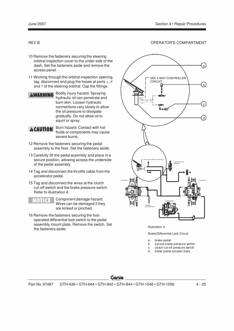
8/14/2019 Genie Manual de Servicio Gth-844
http://slidepdf.com/reader/full/genie-manual-de-servicio-gth-844 95/196
REV B
Section 4 • Repair ProceduresJune 2007
Part No. 97487 GTH-636 • GTH-644 • GTH-842 • GTH-844 • GTH-1048 • GTH-1056 4 - 25
OPERATOR'S COMPARTMENT
10 Remove the fasteners securing the steeringorbitral inspection cover to the under side of thedash. Set the fasteners aside and remove theaccess panel.
11 Working through the orbitral inspection opening,tag, disconnect and plug the hoses at ports L, P
and T of the steering orbitral. Cap the fittings.
Bodily injury hazard. Sprayinghydraulic oil can penetrate and
burn skin. Loosen hydraulicconnections very slowly to allowthe oil pressure to dissipate
gradually. Do not allow oil tosquirt or spray.
Burn hazard. Contact with hot
fluids or components may causesevere burns.
12 Remove the fasteners securing the pedalassembly to the floor. Set the fasteners aside.
13 Carefully lift the pedal assembly and place in a
secure position, allowing access the undersideof the pedal assembly.
14 Tag and disconnect the throttle cable from theaccelerator pedal.
15 Tag and disconnect the wires at the clutchcut-off switch and the brake pressure switch.
Refer to illustration 4.
Component damage hazard.Wires can be damaged if they
are kinked or pinched.
16 Remove the fasteners securing the foot-operated differential lock switch to the pedal
assembly mount plate. Remove the switch. Setthe fasteners aside.
Illustration 4
Brake/Differential Lock Circuit
a brake pedalb service brake pressure switchc clutch cut-off pressure switchd brake pedal actuator body
P
S
3
F
PT
F
PT
REAR AXLE
TRANSMISSION
TO REARLOCK-UP BLOCK
FRONT AXLE
CONTROL BLOCKASSEMBLY
SEE 4-WAY CONTROLLER CIRCUIT
SEE 4-WAY CONTROLLERCIRCUIT
a
b
c
d
8/14/2019 Genie Manual de Servicio Gth-844
http://slidepdf.com/reader/full/genie-manual-de-servicio-gth-844 96/196
REV B
Section 4 • Repair Procedures June 2007
4 - 26 GTH-636 • GTH-644 • GTH-842 • GTH-844 • GTH-1048 • GTH-1056 Part No. 97487
OPERATOR'S COMPARTMENT
17 Open the fuse block access panel locatedunder the dash.
18 Tag and disconnect the blue wire of thedifferential lock switch from the 5 amp fuse in
the lower right corner of the fuse block.
19 Tag, disconnect and plug the hoses at ports F
and P of the brake pedal actuator body. Cap the
fittings.
Bodily injury hazard. Sprayinghydraulic oil can penetrate and
burn skin. Loosen hydraulicconnections very slowly to allow
the oil pressure to dissipategradually. Do not allow oil tosquirt or spray.
Burn hazard. Contact with hotfluids or components may cause
severe burns.
20 Tag and disconnect the red wire from the 20amp fuse in the top left corner of the fuse block.
21 Tag and disconnect the yellow wire of the rear
lock-up switch from the white wire of theparking brake relay.
22 Remove the fasteners securing the steering
column cover to the dash. Remove the covers.Set the fasteners aside.
23 Tag and disconnect the harness connector from
the transmission control lever.
24 Remove the fasteners securing the dashpanel to the operator's compartment. Carefully
move the dash panel towards the front of themachine. Set the fasteners aside
25 Remove the grommet from the dash panel.Set the grommet aside and pull the connectorof the transmission control harness through theopening.
Component damage hazard.Wires can be damaged if they
are kinked or pinched.
26 Tag and disconnect the connector with a redand black wire of the column mounted shifter
harness, from the connector with two blackwires of the instrument panel harness.
27 Tag and disconnect the white wire of the
column mounted shifter wire harness from theparking brake relay.
28 Tag and disconnect the yellow wire from the
parking brake relay.
29 Tag and disconnect the instrument panelharness from the main power harness.
Note: This harness connection is the quick
disconnect screw type.
30 Tag and disconnect the red 8 gauge wires fromone another.
31 Tag and disconnect the white, black and yellow
wires from the sway control switch at the sideconsole assembly.
Component damage hazard.
Wires can be damaged if theyare kinked or pinched.
32 Remove the fasteners securing the seat to the
operator's compartment. Remove the seat.
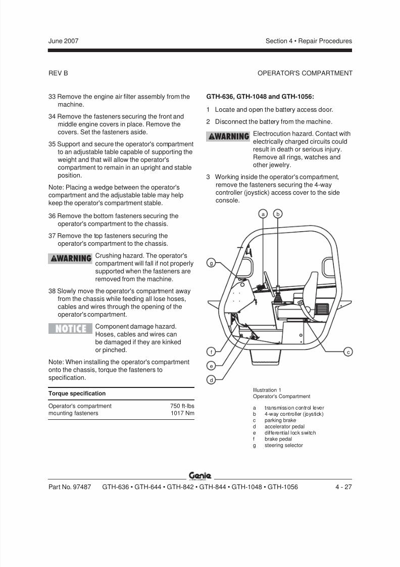
8/14/2019 Genie Manual de Servicio Gth-844
http://slidepdf.com/reader/full/genie-manual-de-servicio-gth-844 97/196
REV B
Section 4 • Repair ProceduresJune 2007
Part No. 97487 GTH-636 • GTH-644 • GTH-842 • GTH-844 • GTH-1048 • GTH-1056 4 - 27
OPERATOR'S COMPARTMENT
a
cf
e
g
b
d
33 Remove the engine air filter assembly from themachine.
34 Remove the fasteners securing the front andmiddle engine covers in place. Remove the
covers. Set the fasteners aside.
35 Support and secure the operator's compartmentto an adjustable table capable of supporting the
weight and that will allow the operator'scompartment to remain in an upright and stable
position.
Note: Placing a wedge between the operator'scompartment and the adjustable table may help
keep the operator's compartment stable.
36 Remove the bottom fasteners securing the
operator's compartment to the chassis.
37 Remove the top fasteners securing theoperator's compartment to the chassis.
Crushing hazard. The operator'scompartment will fall if not properlysupported when the fasteners are
removed from the machine.
38 Slowly move the operator's compartment away
from the chassis while feeding all lose hoses,cables and wires through the opening of theoperator's compartment.
Component damage hazard.
Hoses, cables and wires canbe damaged if they are kinked
or pinched.
Note: When installing the operator's compartmentonto the chassis, torque the fasteners to
specification.
Torque specification
Operator's compartment 750 ft-lbs
mounting fasteners 1017 Nm
GTH-636, GTH-1048 and GTH-1056:1 Locate and open the battery access door.
2 Disconnect the battery from the machine.
Electrocution hazard. Contact with
electrically charged circuits couldresult in death or serious injury.
Remove all rings, watches andother jewelry.
3 Working inside the operator's compartment,
remove the fasteners securing the 4-waycontroller (joystick) access cover to the side
console.
Illustration 1
Operator's Compartment
a transmission control leverb 4-way controller (joystick)c parking braked accelerator pedale differential lock switchf brake pedalg steering selector
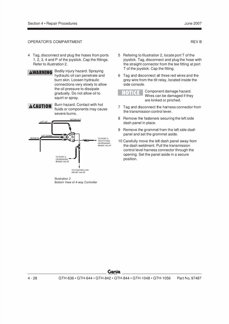
8/14/2019 Genie Manual de Servicio Gth-844
http://slidepdf.com/reader/full/genie-manual-de-servicio-gth-844 98/196
REV B
Section 4 • Repair Procedures June 2007
4 - 28 GTH-636 • GTH-644 • GTH-842 • GTH-844 • GTH-1048 • GTH-1056 Part No. 97487
OPERATOR'S COMPARTMENT
LIFT UP
LIFT DOWN
BOOM IN
BOOM OUT
T
P
2
4
3 1
P
T
TO PORT 2ON BRAKINGBRAKE VALVE
TO PORT 3TEE FITTINGON BRAKINGBRAKE VALVE
TO CONTROLLERRELIEF VALVE
4 Tag, disconnect and plug the hoses from ports1, 2, 3, 4 and P of the joystick. Cap the fittings.Refer to illustration 2.
Bodily injury hazard. Spraying
hydraulic oil can penetrate andburn skin. Loosen hydraulic
connections very slowly to allowthe oil pressure to dissipategradually. Do not allow oil to
squirt or spray.
Burn hazard. Contact with hotfluids or components may cause
severe burns.
Illustration 2Bottom View of 4-way Controller
5 Refering to Illustration 2, locate port T of the joystick. Tag, disconnect and plug the hose withthe straight connector from the tee fitting at portT of the joystick. Cap the fitting.
6 Tag and disconnect all three red wires and thegrey wire from the tilt relay, located inside the
side console.
Component damage hazard.Wires can be damaged if they
are kinked or pinched.
7 Tag and disconnect the harness connector fromthe transmission control lever.
8 Remove the fasteners securing the left side
dash panel in place.
9 Remove the grommet from the left side dashpanel and set the grommet aside.
10 Carefully move the left dash panel away from
the dash weldment. Pull the transmissioncontrol level harness connector through the
opening. Set the panel aside in a secureposition.
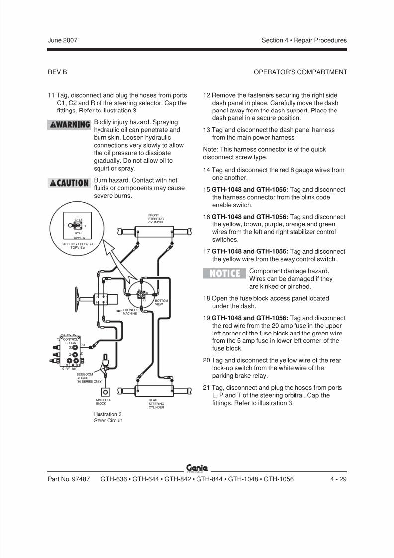
8/14/2019 Genie Manual de Servicio Gth-844
http://slidepdf.com/reader/full/genie-manual-de-servicio-gth-844 99/196
REV B
Section 4 • Repair ProceduresJune 2007
Part No. 97487 GTH-636 • GTH-644 • GTH-842 • GTH-844 • GTH-1048 • GTH-1056 4 - 29
OPERATOR'S COMPARTMENT
ST
CONTROLBLOCK
S PR BKG1 G3
G4 C
G2
RT2 T3
T1
R
P
L
T
REARSTEERINGCYLINDER
MANIFOLDBLOCK
SEE BOOMCIRCUIT(10 SERIES ONLY)
R
FRONT OFMACHINE
C1
P
C2
BOTTOMVIEW
CYL1
CYL2
TOPVIEW
RP
FRONTSTEERINGCYLINDER
STEERING SELECTORTOPVIEW
11 Tag, disconnect and plug the hoses from portsC1, C2 and R of the steering selector. Cap thefittings. Refer to illustration 3.
Bodily injury hazard. Spraying
hydraulic oil can penetrate andburn skin. Loosen hydraulic
connections very slowly to allowthe oil pressure to dissipategradually. Do not allow oil to
squirt or spray.
Burn hazard. Contact with hotfluids or components may cause
severe burns.
12 Remove the fasteners securing the right sidedash panel in place. Carefully move the dashpanel away from the dash support. Place thedash panel in a secure position.
13 Tag and disconnect the dash panel harnessfrom the main power harness.
Note: This harness connector is of the quick
disconnect screw type.
14 Tag and disconnect the red 8 gauge wires from
one another.
15 GTH-1048 and GTH-1056: Tag and disconnect
the harness connector from the blink codeenable switch.
16 GTH-1048 and GTH-1056: Tag and disconnectthe yellow, brown, purple, orange and green
wires from the left and right stabilizer controlswitches.
17 GTH-1048 and GTH-1056: Tag and disconnectthe yellow wire from the sway control switch.
Component damage hazard.
Wires can be damaged if theyare kinked or pinched.
18 Open the fuse block access panel located
under the dash.
19 GTH-1048 and GTH-1056: Tag and disconnectthe red wire from the 20 amp fuse in the upper
left corner of the fuse block and the green wirefrom the 5 amp fuse in lower left corner of thefuse block.
20 Tag and disconnect the yellow wire of the rearlock-up switch from the white wire of theparking brake relay.
21 Tag, disconnect and plug the hoses from portsL, P and T of the steering orbitral. Cap the
fittings. Refer to illustration 3.
Illustration 3Steer Circuit

8/14/2019 Genie Manual de Servicio Gth-844
http://slidepdf.com/reader/full/genie-manual-de-servicio-gth-844 100/196
REV B
Section 4 • Repair Procedures June 2007
4 - 30 GTH-636 • GTH-644 • GTH-842 • GTH-844 • GTH-1048 • GTH-1056 Part No. 97487
OPERATOR'S COMPARTMENT
22 Remove the fasteners securing the brakeactuator covers in place. Set the covers andfasteners aside.
23 Tag, disconnect and plug the hoses from ports
A, P and T of the brake actuator. Cap thefittings. Refer to illustration 4.
Bodily injury hazard. Spraying
hydraulic oil can penetrate andburn skin. Loosen hydraulic
connections very slowly to allowthe oil pressure to dissipategradually. Do not allow oil to
squirt or spray.
Burn hazard. Contact with hotfluids or components may cause
severe burns.
25 Working inside the seat box, tag, disconnectand plug the hoses from ports 1, 2 and 3 of theparking brake valve assembly. Cap the fittings.Refer to illustration 5.
Bodily injury hazard. Sprayinghydraulic oil can penetrate and
burn skin. Loosen hydraulicconnections very slowly to allowthe oil pressure to dissipate
gradually. Do not allow oil tosquirt or spray.
Burn hazard. Contact with hot
fluids or components may causesevere burns.
26 Tag and disconnect the orange and red wires
from the parking brake pressure switch.
Component damage hazard.
Wires can be damaged if theyare kinked or pinched.
27 Remove the fasteners securing the pedal
assembly to the floor.
28 Carefully lift the pedal assembly and place in asecure position, allowing access to theunderside of the accelerator pedal.
29 GTH-636: Tag and disconnect the throttle cablefrom the accelerator pedal.
30 GTH-1048 and GTH-1056: Tag and disconnect
the wire harness connector from the acceleratorpedal.
31 Remove the fasteners securing the foot
operated differential lock switch in place andremove the switch.
32 GTH-1048 and GTH-1056: Tag and
disconnected the blue wire of the differentiallock switch from the 5 amp fuse in the lower
right corner of the fuse block.
Component damage hazard.Wires can be damaged if they
are kinked or pinched.
A
P T
TO CONTROLLER RELIEF VALVESEE 4-WAY CONTROLLER CIRCUIT
TO CLUTCH CUT-OFFPRESSURE SWITCH
TO BRAKE ACCUMULATOR / CONTROL BLOCK
Illustration 4Brake Actuator
24 Remove the fasteners securing the seat box
cover in place. Set the cover and fastenersaside.
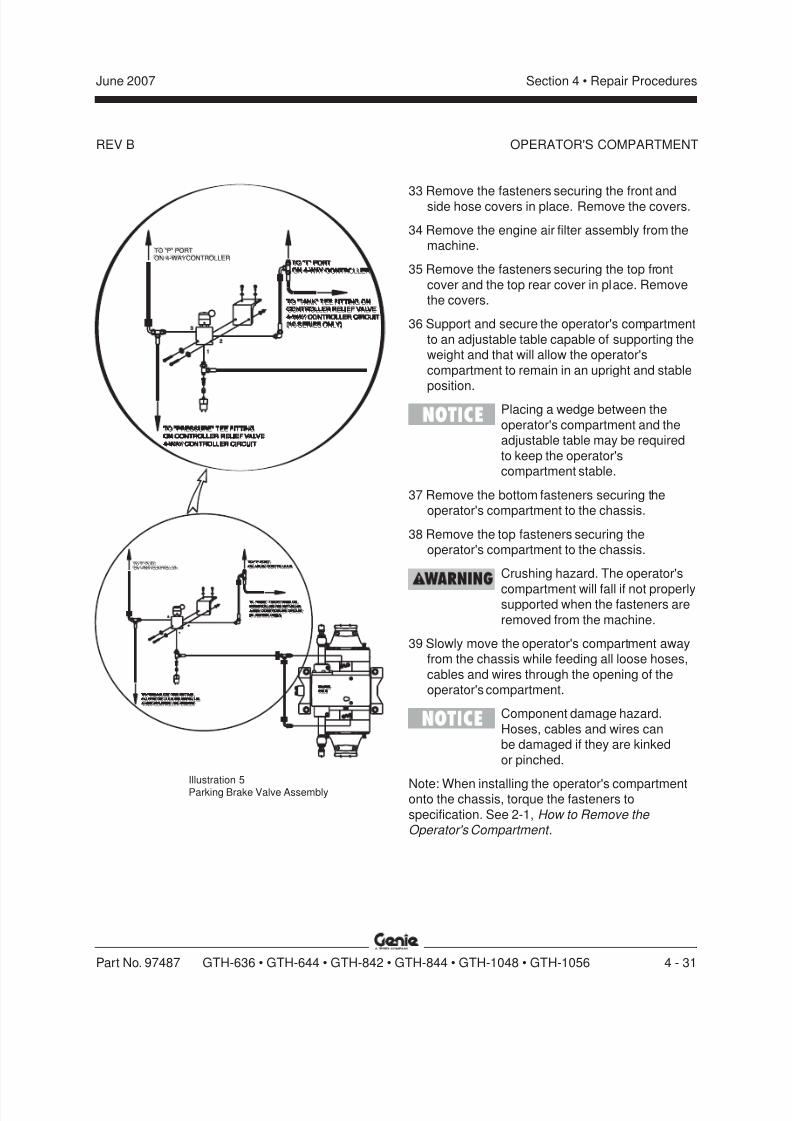
8/14/2019 Genie Manual de Servicio Gth-844
http://slidepdf.com/reader/full/genie-manual-de-servicio-gth-844 101/196
REV B
Section 4 • Repair ProceduresJune 2007
Part No. 97487 GTH-636 • GTH-644 • GTH-842 • GTH-844 • GTH-1048 • GTH-1056 4 - 31
2
1
3
2
1
3
TO "P" PORT
ON 4-WAYCONTROLLER
TO P PORT
ON4-WAYCONTROLLER
TO "TANK" TEE FITTING ONCONTROLLER RELIEF VALVE
4-WAYCONTROLLER CIRCUIT
(10 SERIES ONLY)
TO TANK TEEFITTINGONCONTROLLER RELIEFVALVE
4-WAYCONTROLLER CIRCUIT
10 SERIESONLY)
TO "T" PORT
ON 4-WAY CONTROLLER
TO T PORT
ON4-WAYCONTROLLER
TO "PRESSURE" TEE FITTING
ON CONTROLLER RELIEF VALVE
4-WAYCONTROLLER CIRCUIT
TO PRESSURE TEE FITTING
ONCONTROLLERRELIEFVALVE
4-WAYCONTROLLER CIRCUIT
FRONTAXLEFRONTAXLE
TO "P" PORTON 4-WAYCONTROLLERTO P PORTON 4-WAY CONTROLLER
TO "TANK" TEE FITTING ONCONTROLLER RELIEF VALVE
4-WAYCONTROLLER CIRCUIT(10 SERIES ONLY)
TO TANK TEE FITTING ONCONTROLLERRELIEF VALVE
4-WAYCONTROLLER CIRCUIT 10 SERIES ONLY)
TO "T" PORTON 4-WAY CONTROLLERTO T PORTON 4-WAY CONTROLLER
TO "PRESSURE" TEE FITTINGON CONTROLLER RELIEF VALVE
4-WAYCONTROLLER CIRCUIT
TO PRESSURE TEE FITTINGON CONTROLLER RELIEF VALVE
4-WAYCONTROLLER CIRCUIT
33 Remove the fasteners securing the front andside hose covers in place. Remove the covers.
34 Remove the engine air filter assembly from themachine.
35 Remove the fasteners securing the top front
cover and the top rear cover in place. Removethe covers.
36 Support and secure the operator's compartment
to an adjustable table capable of supporting theweight and that will allow the operator's
compartment to remain in an upright and stableposition.
Placing a wedge between the
operator's compartment and theadjustable table may be required
to keep the operator'scompartment stable.
37 Remove the bottom fasteners securing theoperator's compartment to the chassis.
38 Remove the top fasteners securing theoperator's compartment to the chassis.
Crushing hazard. The operator's
compartment will fall if not properlysupported when the fasteners are
removed from the machine.
39 Slowly move the operator's compartment awayfrom the chassis while feeding all loose hoses,
cables and wires through the opening of theoperator's compartment.
Component damage hazard.
Hoses, cables and wires canbe damaged if they are kinked
or pinched.
Note: When installing the operator's compartmentonto the chassis, torque the fasteners to
specification. See 2-1, How to Remove the Operator's Compartment .
OPERATOR'S COMPARTMENT
Illustration 5Parking Brake Valve Assembly
8/14/2019 Genie Manual de Servicio Gth-844
http://slidepdf.com/reader/full/genie-manual-de-servicio-gth-844 102/196
REV B
Section 4 • Repair Procedures June 2007
4 - 32 GTH-636 • GTH-644 • GTH-842 • GTH-844 • GTH-1048 • GTH-1056 Part No. 97487
OPERATOR'S COMPARTMENT
2-2Machine Controls
How to Remove the SteeringColumn and Orbitral
GTH-644, GTH-842 and GTH-844:
1 Locate and open the battery access door.
2 Disconnect the battery from the machine.
Electrocution hazard. Contact with
electrically charged circuits couldresult in death or serious injury.Remove all rings, watches and
other jewelry.
3 Remove the fasteners securing the steeringorbitral inspection cover in place. Remove the
cover.
4 Working through the orbitral inspection opening,tag, disconnect and plug the hoses at ports L, P,
R and T of the steering orbitral. Cap the fittings.
Bodily injury hazard. Spraying
hydraulic oil can penetrate andburn skin. Loosen hydraulicconnections very slowly to allow
the oil pressure to dissipategradually. Do not allow oil tosquirt or spray.
Burn hazard. Contact with hotfluids or components may causesevere burns.
5 Remove the horn button from the steeringwheel. Remove the nut securing the steeringwheel to the column.
6 Separate the steering wheel from the steering
column and set it aside.
7 Remove the fasteners securing the steeringcolumn cover to the dash. Remove the covers.
8 Tag and disconnect the Deutsch connector
from the transmission control lever.
9 Tag and disconnect the black wire on thesteering column, from the tan wire on the
instrument panel harness.
10 Remove the fasteners securing thetransmission control lever to the column.
Carefully separate the lever from the column.
11 Remove the fasteners securing the dash panelto the operator's compartment.
12 Remove the grommet from the dash panel andset the grommet aside.
13 Carefully move the dash panel towards the front
of the machine and pull the Deutsch connectorthrough the panel hole. Place the dash panel in
a secure position.
Component damage hazard.Wires can be damaged if they are
kinked or pinched.
14 Remove the fasteners securing the steeringcolumn to the steering orbitral. Carefully
separate the components and remove themfrom the dash weldment.
Note: Assistance may be needed to perform this
step.
8/14/2019 Genie Manual de Servicio Gth-844
http://slidepdf.com/reader/full/genie-manual-de-servicio-gth-844 103/196
REV B
Section 4 • Repair ProceduresJune 2007
Part No. 97487 GTH-636 • GTH-644 • GTH-842 • GTH-844 • GTH-1048 • GTH-1056 4 - 33
OPERATOR'S COMPARTMENT
GTH-636, GTH-1048 and GTH-1056:1 Locate and open the battery access door.
2 Disconnect the battery from the machine.
Electrocution hazard. Contact with
electrically charged circuits couldresult in death or serious injury.
Remove all rings, watches andother jewelry.
3 Remove the horn button from the steering
wheel. Remove the nut securing the steeringwheel to the column.
4 Separate the steering wheel from the steering
column and set it aside.
5 Tag and disconnect the Deutsch connectorfrom the transmission control lever.
6 Remove the fasteners securing the
transmission control lever to the column.Carefully separate the lever from the column.
7 Remove the fasteners securing the left and right
dash panels in place.
8 Remove the grommet from the left side dash
panel and set the grommet aside.
9 Carefully move the left dash panel away fromthe dash weldment. Pull the Deutsch connectorthrough the panel hole and place the dash
panel in a secure position.
10 Carefully move the right dash panel away fromthe dash weldment and place in a secure
position.
11 Tag and disconnect the black wire on thesteering column, from the tan wire on theinstrument panel harness.
12 Tag, disconnect and plug the hoses at ports L,
P, R and T of the steering orbitral. Cap thefittings.
Bodily injury hazard. Spraying
hydraulic oil can penetrate andburn skin. Loosen hydraulic
connections very slowly to allowthe oil pressure to dissipategradually. Do not allow oil to
squirt or spray.
Burn hazard. Contact with hotfluids or components may cause
severe burns.
13 Remove the fasteners securing the steering
column to the steering orbitral. Carefullyseparate the components and remove themfrom the dash weldment.
Note: Assistance may be needed to perform thisstep.
8/14/2019 Genie Manual de Servicio Gth-844
http://slidepdf.com/reader/full/genie-manual-de-servicio-gth-844 104/196
REV B
Section 4 • Repair Procedures June 2007
4 - 34 GTH-636 • GTH-644 • GTH-842 • GTH-844 • GTH-1048 • GTH-1056 Part No. 97487
How to Remove the SteeringSelector
GTH-644, GTH-842 and GTH-844:
1 Locate and open the battery access door.
2 Disconnect the battery from the machine.
Electrocution hazard. Contact withelectrically charged circuits couldresult in death or serious injury.
Remove all rings, watches andother jewelry.
3 Remove the fasteners securing the side
console cover in place. Remove the cover.
4 Tag, disconnect and plug the hoses from ports
C1, C2, P and R of the steering selector. Capthe fittings.
Bodily injury hazard. Spraying
hydraulic oil can penetrate andburn skin. Loosen hydraulicconnections very slowly to allow
the oil pressure to dissipategradually. Do not allow oil to
squirt or spray.
Burn hazard. Contact with hotfluids or components may cause
severe burns.
5 Remove the fasteners securing the steeringselector in place. Remove the steering selector.
GTH-636, GTH-1048 and GTH-1056:1 Locate and open the battery access door.
2 Disconnect the battery from the machine.
Electrocution hazard. Contact with
electrically charged circuits couldresult in death or serious injury.
Remove all rings, watches andother jewelry.
3 Tag and disconnect the Deutsch connector
from the transmission control lever.
4 Remove the fasteners securing the left sidedash panel in place.
5 Remove the grommet from the left side dash
panel and set the grommet aside.
6 Carefully move the left side dash panel awayfrom the dash weldment. Pull the Deutsch
connector through the panel hole and place thedash panel in a secure position.
Component damage hazard.
Wires can be damaged if theyare kinked or pinched.
7 Tag, disconnect and plug the hoses from portsC1, C2, P and R of the steering selector. Capthe fittings.
Bodily injury hazard. Spraying
hydraulic oil can penetrate andburn skin. Loosen hydraulic
connections very slowly to allowthe oil pressure to dissipate
gradually. Do not allow oil tosquirt or spray.
Burn hazard. Contact with hot
fluids or components may causesevere burns.
8 Remove the fasteners securing the steering
selector in place. Remove the steering selector.
OPERATOR'S COMPARTMENT
8/14/2019 Genie Manual de Servicio Gth-844
http://slidepdf.com/reader/full/genie-manual-de-servicio-gth-844 105/196
REV B
Section 4 • Repair ProceduresJune 2007
Part No. 97487 GTH-636 • GTH-644 • GTH-842 • GTH-844 • GTH-1048 • GTH-1056 4 - 35
How to Remove the 4-wayController (joystick)
1 Locate and open the battery access door.
2 Disconnect the battery from the machine.
Electrocution hazard. Contact withelectrically charged circuits could
result in death or serious injury.Remove all rings, watches and
other jewelry.
3 Remove the fasteners securing the 4-way
controller (joystick) access cover to the sideconsole. Set the cover to the side.
4 Tag, disconnect and plug the hoses from ports1, 2, 3, 4, P and T of the joystick. Cap the
fittings.
5 Tag and disconnect all three red wires and thegrey wire from the tilt relay.
6 Remove the fasteners securing the joystick to
the side console.
7 Remove the joystick from the side console.
How to Remove the AcceleratorPedal
1 Locate and open the battery access door.
2 Disconnect the battery from the machine.
Electrocution hazard. Contact withelectrically charged circuits could
result in death or serious injury.Remove all rings, watches and
other jewelry.
3 Remove the fasteners securing the pedal
assembly to the floor.
4 Carefully lift the pedal assembly and place in a
secure position to allow access the undersideof the accelerator pedal.
5 GTH-1048 and GTH-1056: Tag and disconnect
the Deutsch connector from accelerator pedal.All other models: Tag and disconnect the
throttle cable from accelerator pedal.
6 Remove the fasteners securing the acceleratorpedal in place.
7 Set the fasteners aside and remove the
accelerator pedal.
OPERATOR'S COMPARTMENT
8/14/2019 Genie Manual de Servicio Gth-844
http://slidepdf.com/reader/full/genie-manual-de-servicio-gth-844 106/196

8/14/2019 Genie Manual de Servicio Gth-844
http://slidepdf.com/reader/full/genie-manual-de-servicio-gth-844 107/196
8/14/2019 Genie Manual de Servicio Gth-844
http://slidepdf.com/reader/full/genie-manual-de-servicio-gth-844 108/196
REV C
Section 4 • Repair Procedures June 2007
4 - 38 GTH-636 • GTH-644 • GTH-842 • GTH-844 • GTH-1048 • GTH-1056 Part No. 97487
Fuel and Hydraulic Tanks
3-1Fuel Tank
How to Remove the Fuel Tank
Explosion and fire hazard. Engine
fuels are combustible. Remove thefuel tank in an open, well-ventilated area away from heaters,
sparks, flames and lightedtobacco. Always have an
approved fire extinguisher within
easy reach.Explosion and fire hazard. Never
drain or store fuel in an opencontainer due to the possibility offire.
Explosion and fire hazard. Whentransferring fuel, connect a
grounding wire between themachine and pump or container.
1 Disconnect the battery from the machine.
Electrocution hazard. Contact with
electrically charged circuits couldresult in death or serious injury.
Remove all rings, watches andother jewelry.
2 Remove the engine air filter assembly from the
machine.
3 Remove the front portion of the engineenclosure assembly from the machine.
4 Remove the fuel filler cap from the tank.
5 Using an approved hand-operated pump, drainthe fuel tank into a container of suitablecapacity. Refer to Section 2, Specifications .
Explosion and fire hazard. When
transferring fuel, connect agrounding wire between the
machine and pump or container.
Note: Be sure to only use a hand operated pumpsuitable for use with gasoline and/or diesel fuel.
6 Tag, disconnect and plug the fuel supply hose.
7 Remove the fuel tank hold-down strap retaining
fasteners. Remove the straps from the fueltank.
8 Support and secure the fuel tank to anappropriate lifting device.
9 Remove the fuel tank from the machine.
Component damage hazard. Thefuel tank is plastic and may
become damaged if allowed to fall.
Note: Clean the fuel tank and inspectfor cracks and other damage before installing.
8/14/2019 Genie Manual de Servicio Gth-844
http://slidepdf.com/reader/full/genie-manual-de-servicio-gth-844 109/196
REV C
Section 4 • Repair ProceduresJune 2007
Part No. 97487 GTH-636 • GTH-644 • GTH-842 • GTH-844 • GTH-1048 • GTH-1056 4 - 39
FUEL AND HYDRAULIC TANKS
3-2Hydraulic Tank
The primary functions of the hydraulic tank are tocool, clean and deaerate the hydraulic fluid duringoperation. It has an internal return line filter with a
filter condition indicator.
How to Remove theHydraulic Tank
Component damage hazard. The
work area and surfaces where thisprocedure will be performed mustbe clean and free of debris that
could get into the hydraulicsystem.
Note: When removing a hose assembly or fitting,
the O-ring on the fitting and/or hose end must bereplaced and then torqued to specification during
installation. Refer to Section 2, Hydraulic Hose and Fitting Torque Specifications.
1 Lower the boom to the stowed position.
2 Raise the machine 15 inches / 40 cm.3 Using a lift with a 1 ton / 1 kg minimum
capacity, remove the counterweight from under
the hydraulic tank at the pivot end of themachine.
Tip over hazard. The
counterweight is critical tomachine stability. If the
counterweight is not installedduring re-assembly of the
machine, the machine will becomeunstable and tip over, resulting in
death or serious injury. Do notoperate the machine without thecounterweight installed onto the
machine.
Crushing hazard. Thecounterweight is extremely heavy.
Keep your body clear whenremoving the counterweight.
4 Remove oil cap from top of hydraulic tank.5 Using an approved hand-operated pump, drain
the hydraulic tank into a suitable container.Refer to Section 2, Specifications .
Bodily injury hazard. Beware of
hot oil. Contact with hot oil maycause severe burns.
6 Remove the fasteners securing the access
covers at the rear of the machine. Remove theaccess covers.
7 Tag, disconnect and plug the hoses at the
hydraulic tank. Cap the fittings.
Bodily injury hazard. Sprayinghydraulic oil can penetrate and
burn skin. Loosen hydraulicconnections very slowly to allow
the oil pressure to dissipategradually. Do not allow oil to squirtor spray.
8 Attach a lifting strap from an overhead crane tothe top of the hydraulic tank. Support the tank.
Do not apply any lifting pressure.
9 Remove the tank mounting fasteners. Lower thetank through the chassis to remove the tank
from the machine.
Crushing hazard. The hydraulictank could become unbalanced
and fall if not properly supportedwhen removed from the machine.
8/14/2019 Genie Manual de Servicio Gth-844
http://slidepdf.com/reader/full/genie-manual-de-servicio-gth-844 110/196
REV B
Section 4 • Repair Procedures June 2007
4 - 40 GTH-636 • GTH-644 • GTH-842 • GTH-844 • GTH-1048 • GTH-1056 Part No. 97487
Engines
4-1Engines
How to Repair theDeutz BF4 2012 Engine
Repair procedures and additional engineinformation is available in the
Deutz 2012 Engine Operation Manual (Deutz part number 0297 9912) and the
Deutz 2012 Engine Workshop Manual (Deutz part number 0312 0361)
Deutz 2012 Operation Manual
Genie part number 108746
Deutz 2012 Workshop Manual
Genie part number 108748
How to Repair thePerkins 1104C Engine
Repair procedures and additional engine
information is available in the
Perkins 1104 Operation and Maintenance Manual (Perkins part number SEBU7833-01) and the
Perkins 1104 Service Manual (Perkins part number RENR9401).
Perkins 1104 Operation and Maintenance Manual
Genie part number 117765
Perkins 1104 Service Manual
Genie part number 117764
How to Repair theJohn Deere 4045T Engine
Repair procedures and additional engineinformation is available in theJohn Deere 4045T270 Operator's Manual
(John Deere part number OMRG25204) and theJohn Deere 4045T275 Operator's Manual
(John Deere part number OMRG33324) and theJohn Deere 4045T Workshop Manual
(John Deere part number CTM104) and theJohn Deere 4045T Alternator Manual (John Deere part number CTM77) and the
John Deere 4045T Fuel Systems Manual (John Deere part number CTM207).
John Deere 4045T270 Operator's Manual
Genie part number 97492
John Deere 4045T275 Operator's Manual
Genie part number 108444
John Deere 4045T Workshop Manual
Genie part number 108443
John Deere 4045T Alternator Manual
Genie part number 108502
John Deere 4045T Fuel Systems Manual
Genie part number 108503
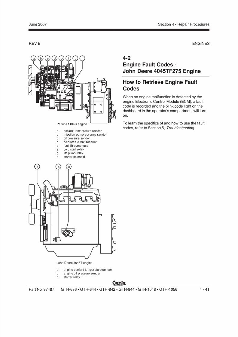
8/14/2019 Genie Manual de Servicio Gth-844
http://slidepdf.com/reader/full/genie-manual-de-servicio-gth-844 111/196
REV B
Section 4 • Repair ProceduresJune 2007
Part No. 97487 GTH-636 • GTH-644 • GTH-842 • GTH-844 • GTH-1048 • GTH-1056 4 - 41
a b c
Perkins 1104C engine
a coolant temperature senderb injection pump advance senderc oil pressure senderd cold start circuit breakere fuel lif t pump fusee cold start relayg lift pump relayh starter solenoid
ENGINES
4-2Engine Fault Codes -John Deere 4045TF275 Engine
How to Retrieve Engine FaultCodes
When an engine malfunction is detected by theengine Electronic Control Module (ECM), a fault
code is recorded and the blink code light on thedashboard in the operator's compartment will turnon.
To learn the specifics of and how to use the fault
codes, refer to Section 5, Troubleshooting .
John Deere 4045T engine
a engine coolant temperature senderb engine oil pressure senderc starter relay
ba c d e f hg

8/14/2019 Genie Manual de Servicio Gth-844
http://slidepdf.com/reader/full/genie-manual-de-servicio-gth-844 112/196
REV C
Section 4 • Repair Procedures June 2007
4 - 42 GTH-636 • GTH-644 • GTH-842 • GTH-844 • GTH-1048 • GTH-1056 Part No. 97487
Transmission
5-1Transmission
How to Remove the Transmission
Bodily injury hazard. This
procedure requires specific repairskills, lifting equipment and asuitable workshop. Attempting this
procedure without these skills andtools could result in death or
serious injury and significant
component damage. Dealerservice is strongly recommended.
Note: When removing a hose assembly or fitting,the O-ring on the fitting and/or hose end must bereplaced and then torqued to specification during
installation. Refer to Section 2, Hydraulic Hose and Fitting Torque Specifications.
Note: Perform this procedure with the engine off
and cool.
1 Disconnect the battery from the machine.
Electrocution hazard. Contact with
electrically charged circuits couldresult in death or serious injury.
Remove all rings, watches andother jewelry.
2 Chock the tires. Remove the driveshafts from
the machine.
3 Remove the drain plug from the radiator andcompletely drain the radiator into a container of
suitable capacity. Refer to Section 2,Specifications .
Burn hazard. Contact with hot
engine components or fluids maycause severe burns.
Dana T12000 transmissiona transmission temperature senderb transmission pressure senderc transmission shift coil 'B'
(drive reverse function)d transmission shift coil 'A'
(drive forward function)e transmission shift coil 'D'
(gear reduction)f transmission shift coil 'E'
(gear reduction)
b ca d e f
Note: refer to electrical schematic for additionaltransmission shift coil information.
4 Tag, disconnect and plug the water lines at theheat exchanger. Cap the fittings.
Note: Do not disconnect the transmission coolerhoses from the heat exchanger.
5 Tag, disconnect and plug the hydraulic line atthe top of the transmission. Cap the fitting.
Bodily injury hazard. Sprayinghydraulic oil can penetrate andburn skin. Loosen hydraulic
connections very slowly to allowthe oil pressure to dissipate
gradually. Do not allow oil to squirtor spray.
6 Tag and disconnect the wire harness from the
transmission.
7 Support and secure the rear of the engine to alifting device of suitable capacity. Do not apply
any lifting pressure.
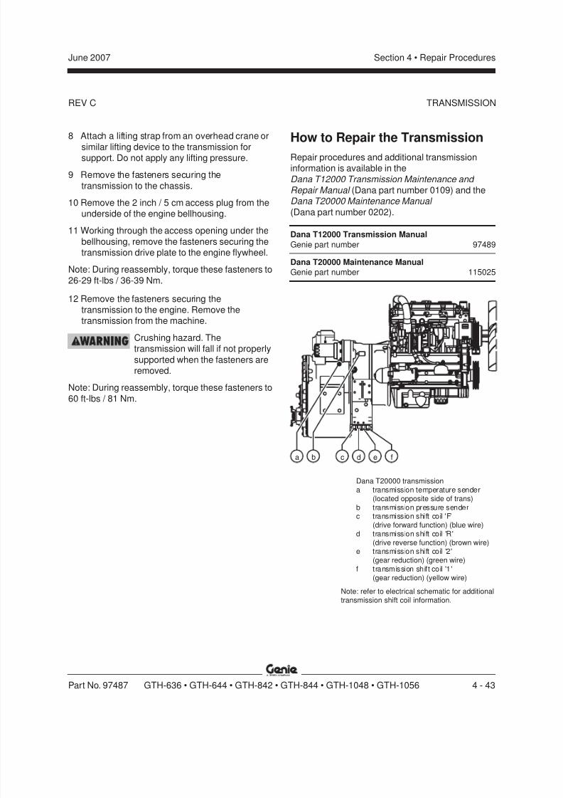
8/14/2019 Genie Manual de Servicio Gth-844
http://slidepdf.com/reader/full/genie-manual-de-servicio-gth-844 113/196
REV C
Section 4 • Repair ProceduresJune 2007
Part No. 97487 GTH-636 • GTH-644 • GTH-842 • GTH-844 • GTH-1048 • GTH-1056 4 - 43
TRANSMISSION
8 Attach a lifting strap from an overhead crane orsimilar lifting device to the transmission forsupport. Do not apply any lifting pressure.
9 Remove the fasteners securing the
transmission to the chassis.
10 Remove the 2 inch / 5 cm access plug from theunderside of the engine bellhousing.
11 Working through the access opening under the
bellhousing, remove the fasteners securing thetransmission drive plate to the engine flywheel.
Note: During reassembly, torque these fasteners to
26-29 ft-lbs / 36-39 Nm.
12 Remove the fasteners securing thetransmission to the engine. Remove thetransmission from the machine.
Crushing hazard. Thetransmission will fall if not properly
supported when the fasteners areremoved.
Note: During reassembly, torque these fasteners to
60 ft-lbs / 81 Nm.
How to Repair the TransmissionRepair procedures and additional transmissioninformation is available in the
Dana T12000 Transmission Maintenance and Repair Manual (Dana part number 0109) and theDana T20000 Maintenance Manual
(Dana part number 0202).
Dana T12000 Transmission Manual
Genie part number 97489
Dana T20000 Maintenance Manual
Genie part number 115025
Dana T20000 transmissiona transmission temperature sender
(located opposite side of trans)b transmission pressure senderc transmission shift coil 'F'
(drive forward function) (blue wire)d transmission shift coil 'R'
(drive reverse function) (brown wire)e transmission shift coil '2'
(gear reduction) (green wire)f transmission shift coil '1'
(gear reduction) (yellow wire)
Note: refer to electrical schematic for additionaltransmission shift coil information.
a b c d e f

8/14/2019 Genie Manual de Servicio Gth-844
http://slidepdf.com/reader/full/genie-manual-de-servicio-gth-844 114/196
REV B
Section 4 • Repair Procedures June 2007
4 - 44 GTH-636 • GTH-644 • GTH-842 • GTH-844 • GTH-1048 • GTH-1056 Part No. 97487
Hydraulic Pump
6-1Hydraulic Pump
How to Test the Function Pump
Note: When removing a hose assembly or fitting,
the fitting and/or hose end must be torqued tospecification during installation. Refer to Section 2,Hydraulic Hose and Fitting Torque Specifications.
1 Tag, disconnect and plug the high pressure
hydraulic hose from the main valve assembly.Cap the fitting on the main valve.
Bodily injury hazard. Spraying
hydraulic oil can penetrate andburn skin. Loosen hydraulicconnections very slowly to allow
the oil pressure to dissipategradually. Do not allow oil to squirt
or spray.
Note: The high pressure hose is the smaller of thetwo hoses.
2 Connect a 0 to 5000 psi / 0 to 350 bar pressuregauge to the high pressure hose disconnected
in step 1.
3 Hold the manual fuel shut-off lever on the
engine in the closed position.
4 Observe the pressure gauge while cranking theengine.
Result:GTH-636: If the pressure gauge reads
2800 psi / 193 bar, immediately stop. The pumpis good.GTH-644, GTH-842, GTH-844 and GTH-1056:
If the pressure gauge reads 3000 psi / 207 bar,immediately stop. The pump is good.
GTH-1048: If the pressure gauge reads3500 psi / 241 bar, immediately stop. The pump
is good.
Result:GTH-636: If the pressure fails to reach
2800 psi / 193 bar, the pump or pump couplingis bad and will need to be serviced or replaced.
GTH-644, GTH-842, GTH-844 and GTH-1056:If the pressure fails to reach3000 psi / 207 bar, the pump or pump coupling
is bad and will need to be serviced or replaced.GTH-1048: If the pressure fails to reach
3500 psi / 241 bar, the pump or pump couplingis bad and will need to be serviced or replaced.
Component damage hazard.
There is no relief valve in thehydraulic pump and the pump can
be damaged if the pressure isallowed to exceed specification.
When testing the pump, crank theengine in one second intervalsuntil the correct pressure is
confirmed. Do not over-pressurizethe pump.
5 Remove the pressure gauge and install the high
pressure hose onto the pump. Torque tospecification. Refer to Section 2, Specifications .
Bodily injury hazard. Sprayinghydraulic oil can penetrate andburn skin. Loosen hydraulic
connections very slowly to allowthe oil pressure to dissipate
gradually. Do not allow oil to squirtor spray.
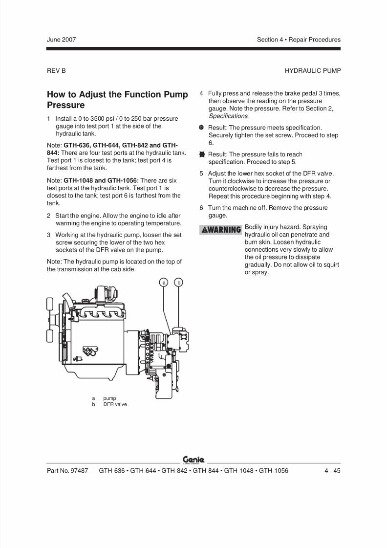
8/14/2019 Genie Manual de Servicio Gth-844
http://slidepdf.com/reader/full/genie-manual-de-servicio-gth-844 115/196
REV B
Section 4 • Repair ProceduresJune 2007
Part No. 97487 GTH-636 • GTH-644 • GTH-842 • GTH-844 • GTH-1048 • GTH-1056 4 - 45
HYDRAULIC PUMP
How to Adjust the Function PumpPressure
1 Install a 0 to 3500 psi / 0 to 250 bar pressuregauge into test port 1 at the side of thehydraulic tank.
Note: GTH-636, GTH-644, GTH-842 and GTH-844: There are four test ports at the hydraulic tank.Test port 1 is closest to the tank; test port 4 is
farthest from the tank.
Note: GTH-1048 and GTH-1056: There are sixtest ports at the hydraulic tank. Test port 1 isclosest to the tank; test port 6 is farthest from the
tank.
2 Start the engine. Allow the engine to idle afterwarming the engine to operating temperature.
3 Working at the hydraulic pump, loosen the set
screw securing the lower of the two hexsockets of the DFR valve on the pump.
Note: The hydraulic pump is located on the top of
the transmission at the cab side.
4 Fully press and release the brake pedal 3 times,then observe the reading on the pressuregauge. Note the pressure. Refer to Section 2,Specifications .
Result: The pressure meets specification.Securely tighten the set screw. Proceed to step
6.
Result: The pressure fails to reachspecification. Proceed to step 5.
5 Adjust the lower hex socket of the DFR valve.
Turn it clockwise to increase the pressure orcounterclockwise to decrease the pressure.
Repeat this procedure beginning with step 4.
6 Turn the machine off. Remove the pressuregauge.
Bodily injury hazard. Spraying
hydraulic oil can penetrate andburn skin. Loosen hydraulicconnections very slowly to allowthe oil pressure to dissipate
gradually. Do not allow oil to squirtor spray.
a pumpb DFR valve
ba
8/14/2019 Genie Manual de Servicio Gth-844
http://slidepdf.com/reader/full/genie-manual-de-servicio-gth-844 116/196
REV B
Section 4 • Repair Procedures June 2007
4 - 46 GTH-636 • GTH-644 • GTH-842 • GTH-844 • GTH-1048 • GTH-1056 Part No. 97487
HYDRAULIC PUMP
How to Remove theFunction Pump
Bodily injury hazard. Thisprocedure requires specific repairskills, lifting equipment and a
suitable workshop. Attempting thisprocedure without these skills and
tools could result in death orserious injury and significant
component damage. Dealerservice is strongly recommended.
Note: When removing a hose assembly or fitting,the O-ring on the fitting and/or hose end must bereplaced and then torqued to specification duringinstallation. Refer to Section 2, Hydraulic Hose and
Fitting Torque Specifications.
Note: Perform this procedure with the engine offand cool.
1 Disconnect the battery from the machine.
Electrocution hazard. Contact withelectrically charged circuits could
result in death or serious injury.
Remove all rings, watches andother jewelry.
2 Remove the oil cap from the top of the hydraulictank.
3 Using an approved hand-operated pump, drain
the hydraulic tank into a suitable container.Refer to Section 2, Specifications .
Bodily injury hazard. Beware of
hot oil. Contact with hot oil maycause severe burns.
4 Remove the engine air filter assembly from themachine.
5 Remove the front portion of the engineenclosure assembly from the machine.
6 Tag and disconnect the wire harness from the
pump.
7 Tag and disconnect the case drain hose at thetop of the pump. Cap the fitting on the pump.
8 Tag, disconnect and plug the large hydraulicsupply line at the pump. Cap the fitting on thepump.
9 Tag, disconnect and plug the high pressurehose at the pump. Cap the fitting on the pump.
Bodily injury hazard. Spraying
hydraulic oil can penetrate andburn skin. Loosen hydraulicconnections very slowly to allow
the oil pressure to dissipategradually. Do not allow oil to squirt
or spray.
10 Remove the fasteners securing the heatexchanger from the chassis bulkhead and let
the heat exchanger hang down.
Burn hazard. Contact with hotengine components may cause
severe burns.
11 Remove the fasteners securing the pump to thetransmission. Remove the pump from the
machine.
8/14/2019 Genie Manual de Servicio Gth-844
http://slidepdf.com/reader/full/genie-manual-de-servicio-gth-844 117/196
REV B
Section 4 • Repair ProceduresJune 2007
Part No. 97487 GTH-636 • GTH-644 • GTH-842 • GTH-844 • GTH-1048 • GTH-1056 4 - 47
How to Install theFunction Pump
1 Carefully install the hydraulic pump onto thetransmission. Install the fasteners and tighten tofinger tight.
2 Torque the fasteners evenly to85 ft-lbs / 115 Nm.
3 Install the smaller high pressure hose onto the
pump outlet. Torque the fasteners to27-37 ft-lbs / 37-50 Nm.
4 Install the larger low pressure hose onto thepump outlet. Install the hose retaining rings andfasteners. Torque the fasteners to
55-66 ft-lbs / 74-90 Nm.
5 Working at the case drain at the top of thepump, fill the pump with hydraulic fluid until thefluid is at the top of the case drain fitting.
6 Install the case drain hose onto the pump andtorque to specification. Refer to Section 2,
Specifications .
7 Securely install the wire harness onto the pump.
8 Install the heat exchanger onto the chassisbulkhead. Install and securely tighten the
fasteners. Do not over tighten.
9 Check the level of the hydraulic fluid in thehydraulic tank. Add fluid if needed.
10 Working inside the cab, press and hold the PUMP
OFF button.
Note: The PUMP OFF button is located under the
steering wheel.
11 Start the engine.12 Release the PUMP OFF button for two seconds.
13 Press and hold the PUMP OFF button for onesecond, then release.
14 Repeat step 13.
15 Turn the machine off.
HYDRAULIC PUMP

8/14/2019 Genie Manual de Servicio Gth-844
http://slidepdf.com/reader/full/genie-manual-de-servicio-gth-844 118/196
REV C
Section 4 • Repair Procedures June 2007
4 - 48 GTH-636 • GTH-644 • GTH-842 • GTH-844 • GTH-1048 • GTH-1056 Part No. 97487
AA
AD
AB
AC
4
1
2
3
T A N K
H Y D R
A U L I C
Note: 'alpha'callouts referto corresponding notes onthe hydraulic schematic
Manifolds
7-1Main Valve Manifold Components
The main valve manifold is located on the front of the hydraulic tank at the tailpipe side of the machine.
Index Schematic
No. Description Item Function Torque
1 Directional valve, pilot operated .......AA .......... Boom extend/retract ....................................88 in-lbs / 10 Nm
2 Directional valve, pilot operated .......AB .......... Lifting fork level ...........................................88 in-lbs / 10 Nm
3 Directional valve, pilot operated ...... AC .......... Boom up/down ............................................88 in-lbs / 10 Nm
4 Relief valve, 3650 psi / 251 bar ....... AD .......... Manifold relief............................................ 73 ft-lbs / 100 Nm

8/14/2019 Genie Manual de Servicio Gth-844
http://slidepdf.com/reader/full/genie-manual-de-servicio-gth-844 119/196
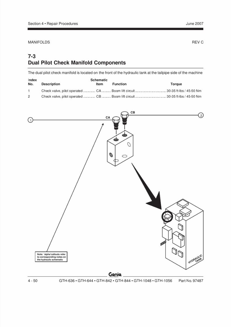
8/14/2019 Genie Manual de Servicio Gth-844
http://slidepdf.com/reader/full/genie-manual-de-servicio-gth-844 120/196
REV C
Section 4 • Repair Procedures June 2007
4 - 50 GTH-636 • GTH-644 • GTH-842 • GTH-844 • GTH-1048 • GTH-1056 Part No. 97487
CA
CB
T A N K
H Y D R
A U L I C
1
2
Note: 'alpha'callouts referto corresponding notes onthe hydraulic schematic
MANIFOLDS
7-3Dual Pilot Check Manifold Components
The dual pilot check manifold is located on the front of the hydraulic tank at the tailpipe side of the machine
Index Schematic
No. Description Item Function Torque
1 Check valve, pilot operated ............. CA .......... Boom lift circuit .................................. 30-35 ft-lbs / 45-50 Nm
2 Check valve, pilot operated ............. CB .......... Boom lift circuit .................................. 30-35 ft-lbs / 45-50 Nm
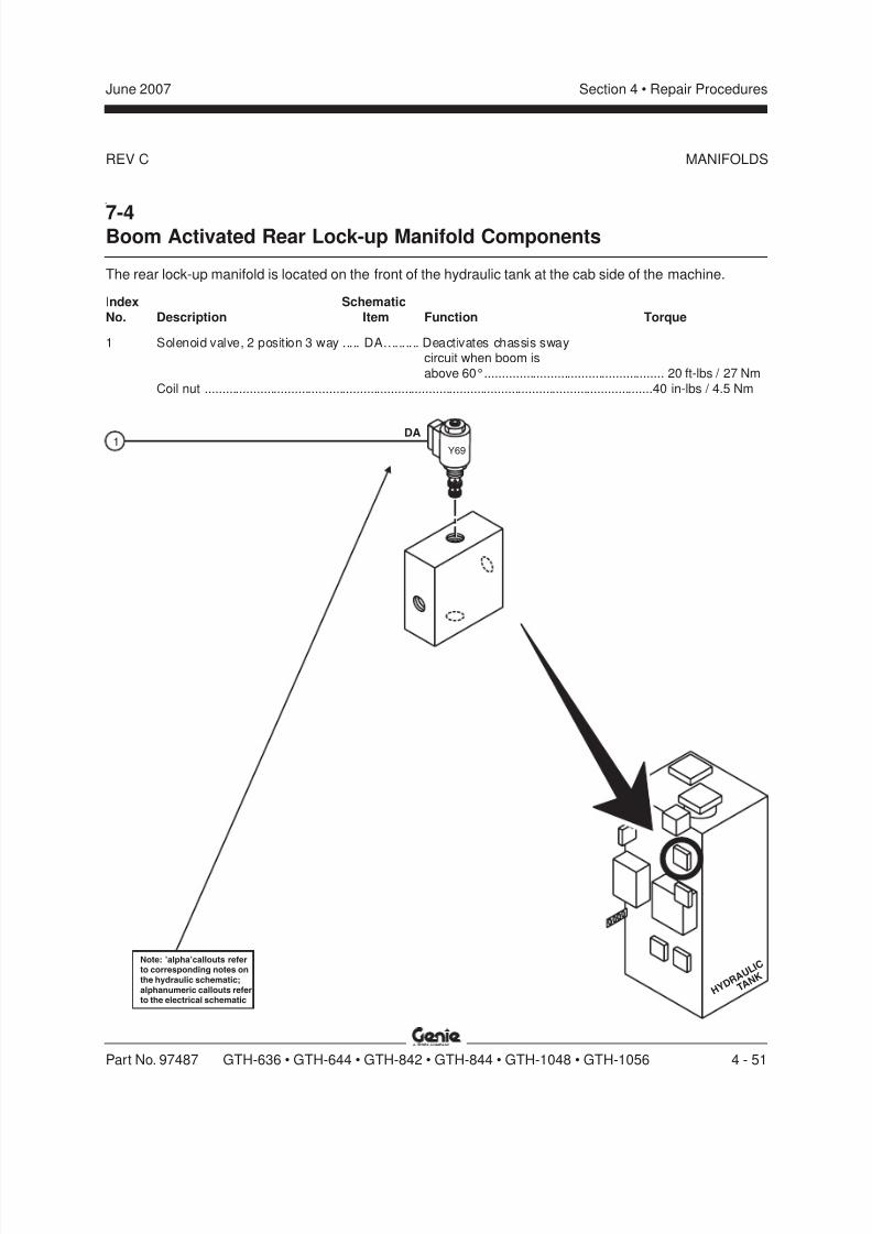
8/14/2019 Genie Manual de Servicio Gth-844
http://slidepdf.com/reader/full/genie-manual-de-servicio-gth-844 121/196
REV C
Section 4 • Repair ProceduresJune 2007
Part No. 97487 GTH-636 • GTH-644 • GTH-842 • GTH-844 • GTH-1048 • GTH-1056 4 - 51
DAY69
T A N K
H Y D R
A U L I C
1
Note: 'alpha'callouts referto corresponding notes onthe hydraulic schematic;alphanumeric callouts referto the electrical schematic
MANIFOLDS
7-4Boom Activated Rear Lock-up Manifold Components
The rear lock-up manifold is located on the front of the hydraulic tank at the cab side of the machine.
Index Schematic
No. Description Item Function Torque
1 Solenoid valve, 2 position 3 way ..... DA.......... Deactivates chassis swaycircuit when boom is
above 60°.................................................... 20 ft-lbs / 27 Nm
Coil nut ..................................................................................................................................40 in-lbs / 4.5 Nm
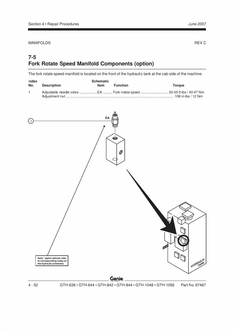
8/14/2019 Genie Manual de Servicio Gth-844
http://slidepdf.com/reader/full/genie-manual-de-servicio-gth-844 122/196
REV C
Section 4 • Repair Procedures June 2007
4 - 52 GTH-636 • GTH-644 • GTH-842 • GTH-844 • GTH-1048 • GTH-1056 Part No. 97487
EA1
T A N K
H Y D R
A U L I C
Note: 'alpha'callouts referto corresponding notes onthe hydraulic schematic
MANIFOLDS
7-5Fork Rotate Speed Manifold Components (option)
The fork rotate speed manifold is located on the front of the hydraulic tank at the cab side of the machine.
Index Schematic
No. Description Item Function Torque
1 Adjustable needle valve ...................EA .......... Fork rotate speed.............................. 30-35 ft-lbs / 40-47 NmAdjustment nut ..................................................................................................................... 108 in-lbs / 12 Nm

8/14/2019 Genie Manual de Servicio Gth-844
http://slidepdf.com/reader/full/genie-manual-de-servicio-gth-844 123/196
REV C
Section 4 • Repair ProceduresJune 2007
Part No. 97487 GTH-636 • GTH-644 • GTH-842 • GTH-844 • GTH-1048 • GTH-1056 4 - 53
FA FB
FC
FD
1
4
3
2
T A N K
H Y D R
A U L I C
Note: 'alpha'callouts referto corresponding notes onthe hydraulic schematic
MANIFOLDS
7-6Control Block Manifold Components
The control block manifold is located on the front of the hydraulic tank at the cab side of the machine.
Index Schematic
No. Description Item Function Torque
1 Adjustable needle valve ................... FA .......... Chassis sway speed ......................... 30-35 ft-lbs / 40-47 NmAdjustment nut ..................................................................................................................... 108 in-lbs / 12 Nm
2 Pressure reducing/relief valve,pilot operated, 500 psi / 34.5 bar......FB .......... Pilot pressure for boom up/down,
boom extend/retract and parking
brake circuits ..................................... 30-35 ft-lbs / 40-47 Nm
3 Pressure reducing/relief valve,
pilot operated, 2250 psi / 155 bar .....FC .......... Steer left/right andfork rotate (option) circuits ................ 30-35 ft-lbs / 40-47 Nm
4 Check valve ......................................FD .......... Brake circuit ...................................... 30-35 ft-lbs / 40-47 Nm

8/14/2019 Genie Manual de Servicio Gth-844
http://slidepdf.com/reader/full/genie-manual-de-servicio-gth-844 124/196
REV C
Section 4 • Repair Procedures June 2007
4 - 54 GTH-636 • GTH-644 • GTH-842 • GTH-844 • GTH-1048 • GTH-1056 Part No. 97487
T A N K
H Y D R
A U L I C
T A N K
H Y D R
A U L I C
1GA Y72A Y72B GB
2
Note: 'alpha'callouts referto corresponding notes onthe hydraulic schematic;alphanumeric callouts referto the electrical schematic
MANIFOLDS
7-7Fork Tilt Manifolds Components
The fork tilt manifolds, used only on machines with single joystick, are located on the front of the hydraulictank at the cab side of the machine.
Index Schematic
No. Description Item Function Torque
— Coil nut (items GA and GB) ...................................................................................................40 in-lbs / 4.5 Nm
1 Solenoid valve, 2 position 4 way ..... GA.......... Tilts lifting forks down ................................. 20 ft-lbs / 27 Nm
2 Solenoid valve, 2 position 4 way ..... GB.......... Tilts lifting forks up ...................................... 20 ft-lbs / 27 Nm

8/14/2019 Genie Manual de Servicio Gth-844
http://slidepdf.com/reader/full/genie-manual-de-servicio-gth-844 125/196
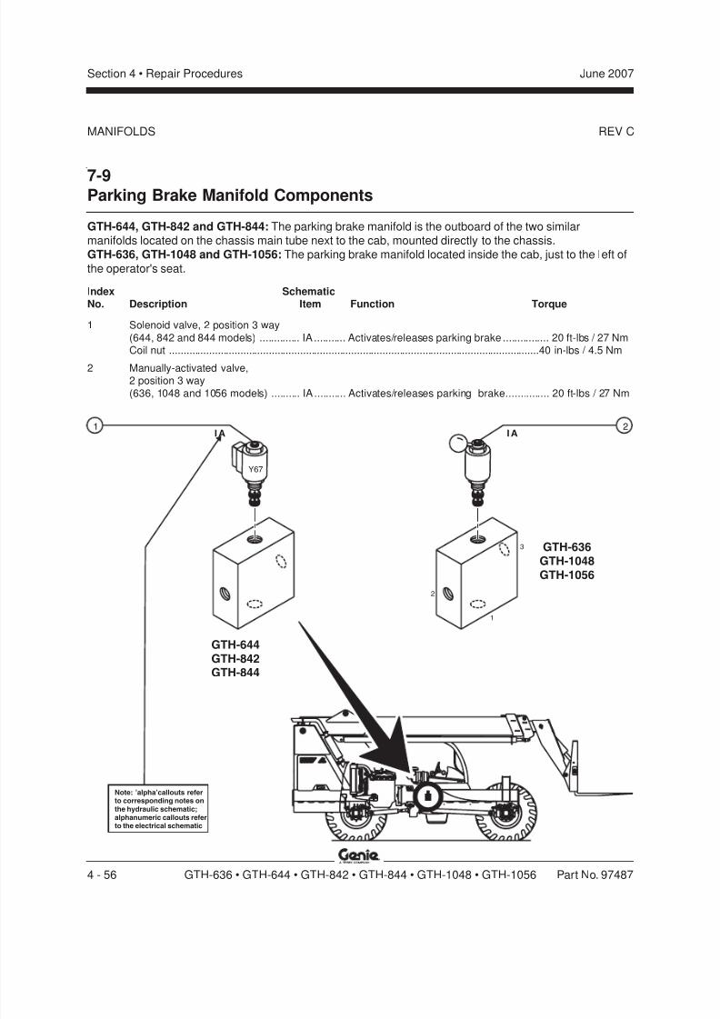
8/14/2019 Genie Manual de Servicio Gth-844
http://slidepdf.com/reader/full/genie-manual-de-servicio-gth-844 126/196
REV C
Section 4 • Repair Procedures June 2007
4 - 56 GTH-636 • GTH-644 • GTH-842 • GTH-844 • GTH-1048 • GTH-1056 Part No. 97487
MANIFOLDS
7-9Parking Brake Manifold Components
GTH-644, GTH-842 and GTH-844: The parking brake manifold is the outboard of the two similarmanifolds located on the chassis main tube next to the cab, mounted directly to the chassis.GTH-636, GTH-1048 and GTH-1056: The parking brake manifold located inside the cab, just to the left of
the operator's seat.
Index SchematicNo. Description Item Function Torque
1 Solenoid valve, 2 position 3 way
(644, 842 and 844 models) .............. IA ........... Activates/releases parking brake ................ 20 ft-lbs / 27 NmCoil nut ..................................................................................................................................40 in-lbs / 4.5 Nm
2 Manually-activated valve,2 position 3 way
(636, 1048 and 1056 models) .......... IA ........... Activates/releases parking brake............... 20 ft-lbs / 27 Nm
I A
Y67
1
Note: 'alpha'callouts referto corresponding notes onthe hydraulic schematic;alphanumeric callouts referto the electrical schematic
GTH-644GTH-842GTH-844
I A
GTH-636GTH-1048GTH-1056
2
3
2
1
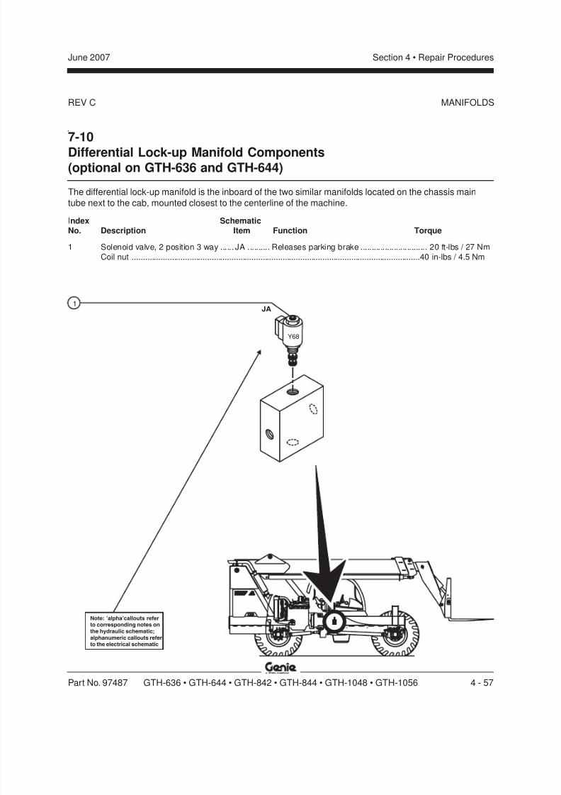
8/14/2019 Genie Manual de Servicio Gth-844
http://slidepdf.com/reader/full/genie-manual-de-servicio-gth-844 127/196
REV C
Section 4 • Repair ProceduresJune 2007
Part No. 97487 GTH-636 • GTH-644 • GTH-842 • GTH-844 • GTH-1048 • GTH-1056 4 - 57
JA1
Y68
Note: 'alpha'callouts referto corresponding notes onthe hydraulic schematic;alphanumeric callouts referto the electrical schematic
MANIFOLDS
7-10Differential Lock-up Manifold Components(optional on GTH-636 and GTH-644)
The differential lock-up manifold is the inboard of the two similar manifolds located on the chassis main
tube next to the cab, mounted closest to the centerline of the machine.
Index SchematicNo. Description Item Function Torque
1 Solenoid valve, 2 position 3 way ...... JA .......... Releases parking brake .............................. 20 ft-lbs / 27 Nm
Coil nut ..................................................................................................................................40 in-lbs / 4.5 Nm
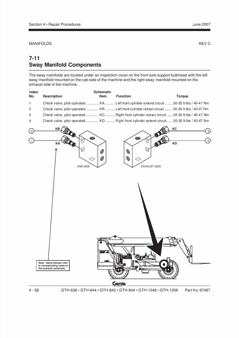
8/14/2019 Genie Manual de Servicio Gth-844
http://slidepdf.com/reader/full/genie-manual-de-servicio-gth-844 128/196
REV C
Section 4 • Repair Procedures June 2007
4 - 58 GTH-636 • GTH-644 • GTH-842 • GTH-844 • GTH-1048 • GTH-1056 Part No. 97487
KB
KA
2
41
3
Note: 'alpha'callouts referto corresponding notes onthe hydraulic schematic
CAB SIDE EXHAUST SIDE
KC
KD
MANIFOLDS
7-11Sway Manifold Components
The sway manifolds are located under an inspection cover on the front axle support bulkhead with the leftsway manifold mounted on the cab side of the machine and the right sway manifold mounted on theexhaust side of the machine.
Index Schematic
No. Description Item Function Torque
1 Check valve, pilot operated ..............KA .......... Left front cylinder extend circuit ........ 30-35 ft-lbs / 40-47 Nm
2 Check valve, pilot operated ..............KB .......... Left front cylinder retract circuit......... 30-35 ft-lbs / 40-47 Nm
3 Check valve, pilot operated ............. KC .......... Right front cylinder retract circuit ...... 30-35 ft-lbs / 40-47 Nm
4 Check valve, pilot operated ............. KD .......... Right front cylinder extend circuit ..... 30-35 ft-lbs / 40-47 Nm

8/14/2019 Genie Manual de Servicio Gth-844
http://slidepdf.com/reader/full/genie-manual-de-servicio-gth-844 129/196
REV C
Section 4 • Repair ProceduresJune 2007
Part No. 97487 GTH-636 • GTH-644 • GTH-842 • GTH-844 • GTH-1048 • GTH-1056 4 - 59
LA1
Note: 'alpha'callouts referto corresponding notes onthe hydraulic schematic
MANIFOLDS
7-12Fork Rotate Manifold Components (option)
If equipped with the fork rotate option, the fork rotate manifold is located under the rear lock-up manifoldon the rear axle support bulkhead at the cab side of the machine.
Index Schematic
No. Description Item Function Torque
1 Solenoid valve, 3 position 4 way
with manual override ........................LA .......... Rotate forks clockwise orcounterclockwise
Coil nut ..................................................................................................................................30 in-lbs / 3.4 Nm
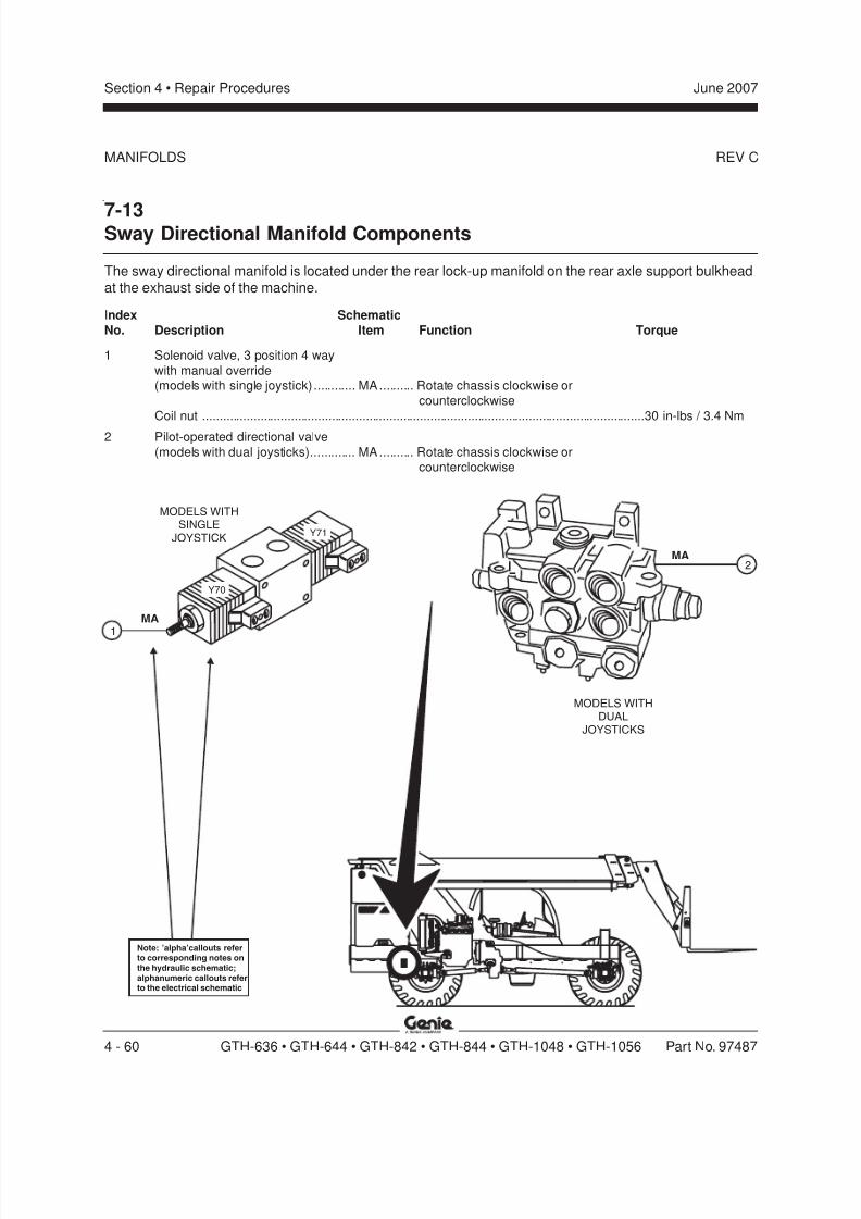
8/14/2019 Genie Manual de Servicio Gth-844
http://slidepdf.com/reader/full/genie-manual-de-servicio-gth-844 130/196
REV C
Section 4 Repair Procedures June 2007
4 - 60 GTH-636 • GTH-644 • GTH-842 • GTH-844 • GTH-1048 • GTH-1056 Part No. 97487
MANIFOLDS
7-13Sway Directional Manifold Components
The sway directional manifold is located under the rear lock-up manifold on the rear axle support bulkheadat the exhaust side of the machine.
Index Schematic
No. Description Item Function Torque
1 Solenoid valve, 3 position 4 way
with manual override(models with single joystick) ............ MA.......... Rotate chassis clockwise or
counterclockwise
Coil nut ..................................................................................................................................30 in-lbs / 3.4 Nm
2 Pilot-operated directional valve
(models with dual joysticks)............. MA.......... Rotate chassis clockwise orcounterclockwise
MA1
Y71
Y70
Note: 'alpha'callouts referto corresponding notes onthe hydraulic schematic;alphanumeric callouts referto the electrical schematic
MA2
MODELS WITHSINGLE
JOYSTICK
MODELS WITHDUAL
JOYSTICKS

8/14/2019 Genie Manual de Servicio Gth-844
http://slidepdf.com/reader/full/genie-manual-de-servicio-gth-844 131/196
REV C
Section 4 • Repair ProceduresJune 2007
Part No. 97487 GTH-636 • GTH-644 • GTH-842 • GTH-844 • GTH-1048 • GTH-1056 4 - 61
7-14Outrigger Manifold Components -GTH-1048 and GTH-1056
The outrigger manifold is located under the inspection cover on the front axle support bulkhead.
Index Schematic
No. Description Item Function Torque
— Coil nut ..................................................................................................................................30 in-lbs / 3.4 Nm
1 Solenoid valve, 3 position 4 way
with manual override ....................... NA .......... Outrigger extend/retract circuit, cab side
2 Solenoid valve, 3 position 4 way
with manual override ....................... NB .......... Outrigger extend/retract circuit, exhaust side
MANIFOLDS
NA1 2
NB
Y73
Y74Y76
Y75
Note: 'alpha'callouts referto corresponding notes onthe hydraulic schematic;alphanumeric callouts referto the electrical schematic
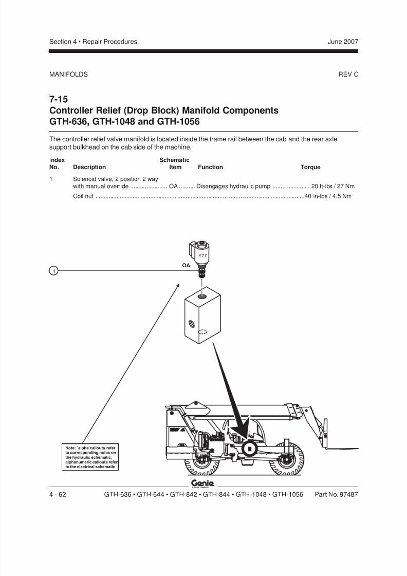
8/14/2019 Genie Manual de Servicio Gth-844
http://slidepdf.com/reader/full/genie-manual-de-servicio-gth-844 132/196
REV C
Section 4 • Repair Procedures June 2007
4 - 62 GTH-636 • GTH-644 • GTH-842 • GTH-844 • GTH-1048 • GTH-1056 Part No. 97487
7-15Controller Relief (Drop Block) Manifold ComponentsGTH-636, GTH-1048 and GTH-1056
The controller relief valve manifold is located inside the frame rail between the cab and the rear axle
support bulkhead on the cab side of the machine.
Index SchematicNo. Description Item Function Torque
1 Solenoid valve, 2 position 2 way
with manual override ....................... OA .......... Disengages hydraulic pump ....................... 20 ft-lbs / 27 Nm
Coil nut ..................................................................................................................................40 in-lbs / 4.5 Nm
MANIFOLDS
OA1
Y77
Note: 'alpha'callouts referto corresponding notes onthe hydraulic schematic;alphanumeric callouts referto the electrical schematic
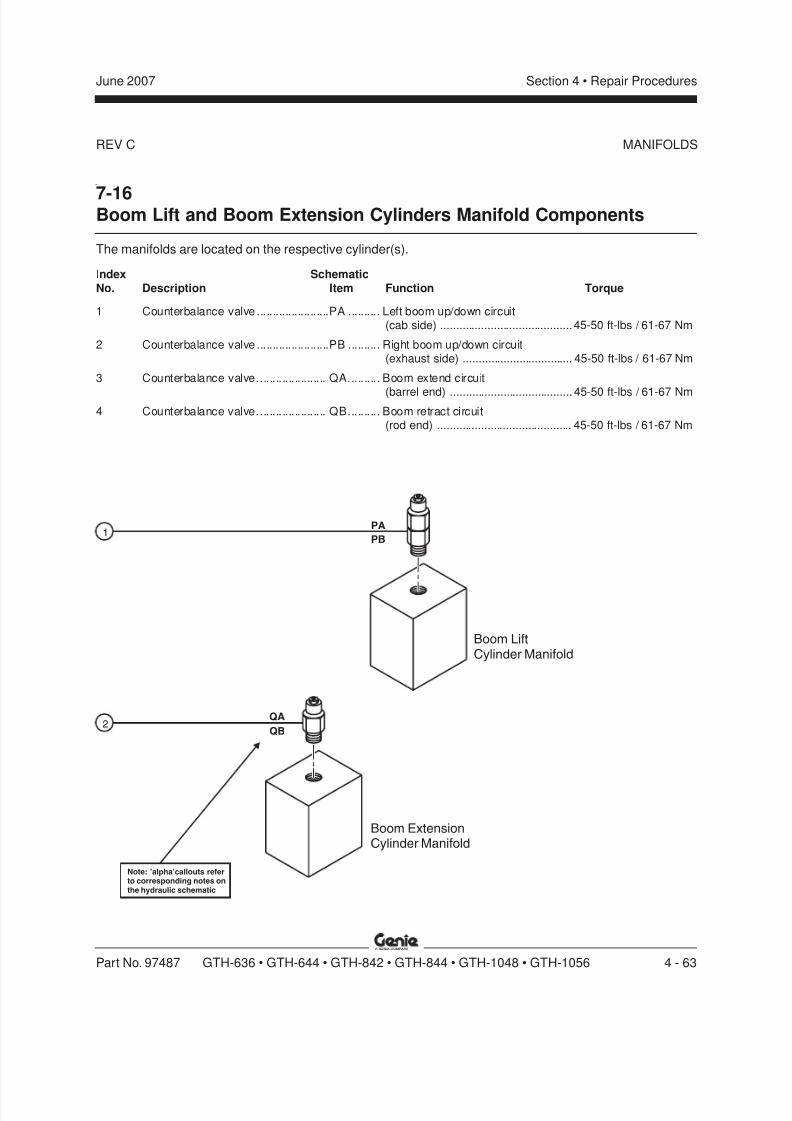
8/14/2019 Genie Manual de Servicio Gth-844
http://slidepdf.com/reader/full/genie-manual-de-servicio-gth-844 133/196
REV C
Section 4 • Repair ProceduresJune 2007
Part No. 97487 GTH-636 • GTH-644 • GTH-842 • GTH-844 • GTH-1048 • GTH-1056 4 - 63
PA
PB
QA
QB
Note: 'alpha'callouts referto corresponding notes onthe hydraulic schematic
1
2
Boom LiftCylinder Manifold
Boom ExtensionCylinder Manifold
7-16Boom Lift and Boom Extension Cylinders Manifold Components
The manifolds are located on the respective cylinder(s).
Index Schematic
No. Description Item Function Torque
1 Counterbalance valve .......................PA .......... Left boom up/down circuit(cab side) .......................................... 45-50 ft-lbs / 61-67 Nm
2 Counterbalance valve .......................PB .......... Right boom up/down circuit(exhaust side) ................................... 45-50 ft-lbs / 61-67 Nm
3 Counterbalance valve...................... QA.......... Boom extend circuit
(barrel end) ....................................... 45-50 ft-lbs / 61-67 Nm4 Counterbalance valve...................... QB.......... Boom retract circuit
(rod end) ........................................... 45-50 ft-lbs / 61-67 Nm
MANIFOLDS

8/14/2019 Genie Manual de Servicio Gth-844
http://slidepdf.com/reader/full/genie-manual-de-servicio-gth-844 134/196
REV C
Section 4 • Repair Procedures June 2007
4 - 64 GTH-636 • GTH-644 • GTH-842 • GTH-844 • GTH-1048 • GTH-1056 Part No. 97487
RA
RB
RC
1
2
3
Note: 'alpha'callouts referto corresponding notes onthe hydraulic schematic
MANIFOLDS
7-17Fork Level Cylinder Manifold Components
If equipped with the fork rotate option, the fork rotate cylinder manifold is located on the cylinder.
Index Schematic
No. Description Item Function Torque
1 Check valve, pilot operated ............. RA .......... Fork up circuit ................................... 30-35 ft-lbs / 40-47 Nm
2 Counterbalance valve ...................... RB .......... Fork up circuit ................................... 30-35 ft-lbs / 40-47 Nm
3 Check valve, pilot operated ............. RC .......... Fork down circuit ............................... 30-35 ft-lbs / 40-47 Nm
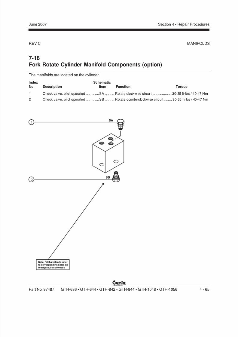
8/14/2019 Genie Manual de Servicio Gth-844
http://slidepdf.com/reader/full/genie-manual-de-servicio-gth-844 135/196
REV C
Section 4 • Repair ProceduresJune 2007
Part No. 97487 GTH-636 • GTH-644 • GTH-842 • GTH-844 • GTH-1048 • GTH-1056 4 - 65
MANIFOLDS
SA
SB
Note: 'alpha'callouts referto corresponding notes onthe hydraulic schematic
1
2
7-18Fork Rotate Cylinder Manifold Components (option)
The manifolds are located on the cylinder.
Index Schematic
No. Description Item Function Torque
1 Check valve, pilot operated ..............SA .......... Rotate clockwise circuit .................... 30-35 ft-lbs / 40-47 Nm
2 Check valve, pilot operated ..............SB .......... Rotate counterclockwise circuit ........ 30-35 ft-lbs / 40-47 Nm
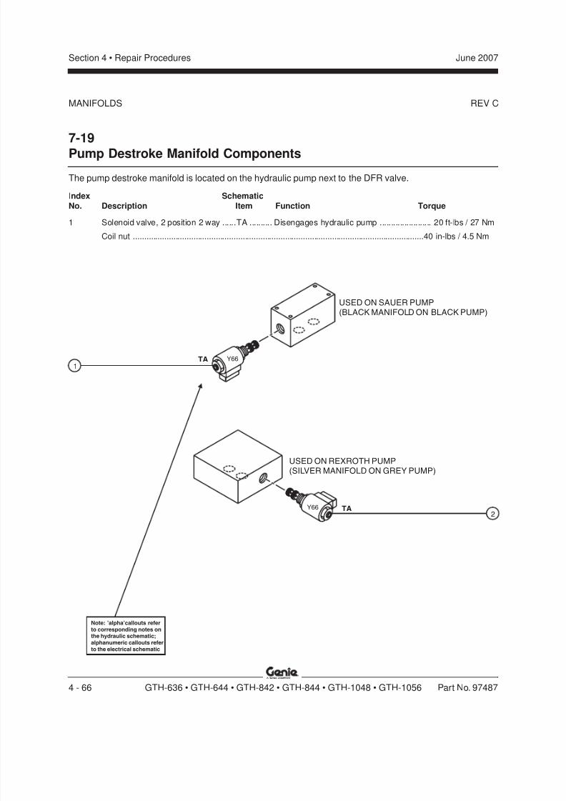
8/14/2019 Genie Manual de Servicio Gth-844
http://slidepdf.com/reader/full/genie-manual-de-servicio-gth-844 136/196
REV C
Section 4 • Repair Procedures June 2007
4 - 66 GTH-636 • GTH-644 • GTH-842 • GTH-844 • GTH-1048 • GTH-1056 Part No. 97487
7-19Pump Destroke Manifold Components
The pump destroke manifold is located on the hydraulic pump next to the DFR valve.
Index Schematic
No. Description Item Function Torque
1 Solenoid valve, 2 position 2 way ......TA .......... Disengages hydraulic pump ....................... 20 ft-lbs / 27 Nm
Coil nut ..................................................................................................................................40 in-lbs / 4.5 Nm
MANIFOLDS
TA1
2TA
USED ON SAUER PUMP(BLACK MANIFOLD ON BLACK PUMP)
USED ON REXROTH PUMP(SILVER MANIFOLD ON GREY PUMP)
Y66
Y66
Note: 'alpha'callouts referto corresponding notes onthe hydraulic schematic;alphanumeric callouts referto the electrical schematic

8/14/2019 Genie Manual de Servicio Gth-844
http://slidepdf.com/reader/full/genie-manual-de-servicio-gth-844 137/196
REV C
Section 4 • Repair ProceduresJune 2007
Part No. 97487 GTH-636 • GTH-644 • GTH-842 • GTH-844 • GTH-1048 • GTH-1056 4 - 67
MANIFOLDS
7-20Extend Cylinder Relief Manifold Components -GTH-636, GTH-1048 and GTH-1056
The extend cylinder relief manifold is located on the dump block at the front of the hydraulic tank.
Index Schematic
No. Description Item Function Torque
1 Relief valve, 2000 psi / 137.9 bar(GTH-636 from serial number
GTH0606A-8418 toGTH0606A-9022) ............................ UA .......... Boom extend relief ...................................... 20 ft-lbs / 27 Nm
— Relief valve, 2500 psi / 172.3 bar(GTH-1048 and GTH-1056)............. UA .......... Boom extend relief ...................................... 20 ft-lbs / 27 Nm
1
Note: 'alpha'callouts referto corresponding notes onthe hydraulic schematic
UA
T A N K
H Y D R
A U L I C
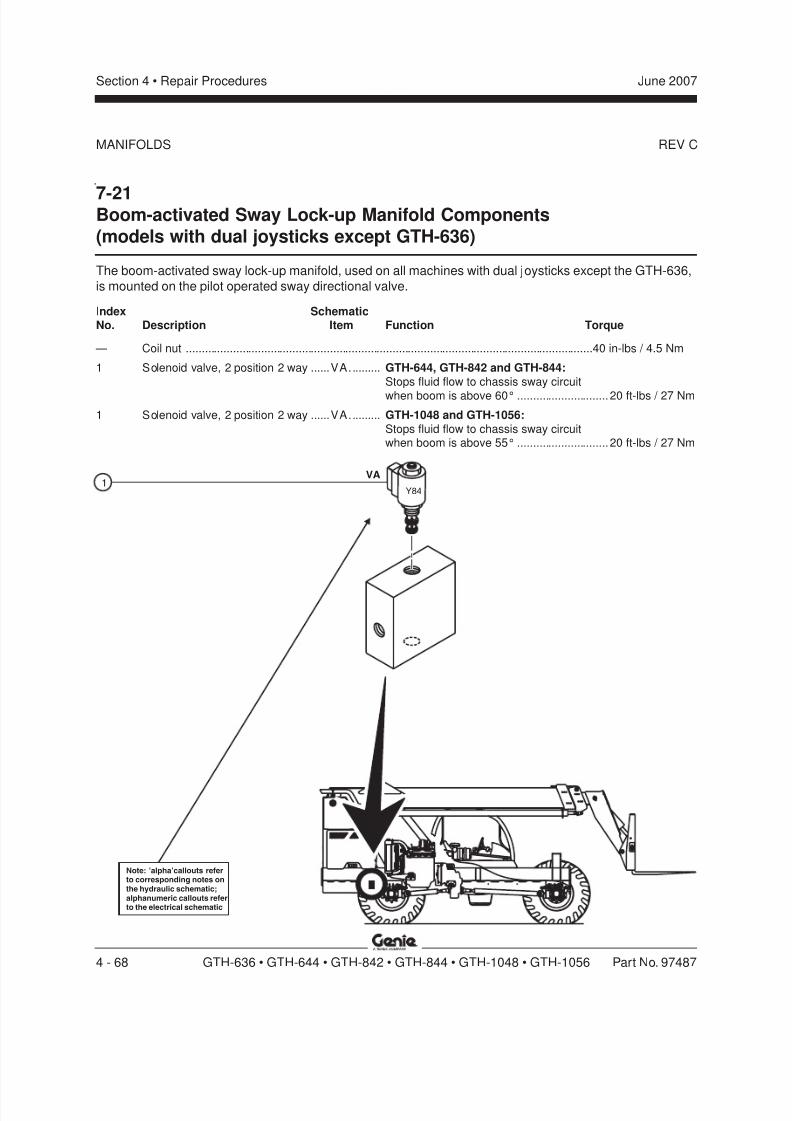
8/14/2019 Genie Manual de Servicio Gth-844
http://slidepdf.com/reader/full/genie-manual-de-servicio-gth-844 138/196
REV C
Section 4 • Repair Procedures June 2007
4 - 68 GTH-636 • GTH-644 • GTH-842 • GTH-844 • GTH-1048 • GTH-1056 Part No. 97487
7-21Boom-activated Sway Lock-up Manifold Components(models with dual joysticks except GTH-636)
The boom-activated sway lock-up manifold, used on all machines with dual joysticks except the GTH-636,
is mounted on the pilot operated sway directional valve.
Index SchematicNo. Description Item Function Torque
— Coil nut ..................................................................................................................................40 in-lbs / 4.5 Nm
1 Solenoid valve, 2 position 2 way ......VA.......... GTH-644, GTH-842 and GTH-844:
Stops fluid flow to chassis sway circuit
when boom is above 60° ............................. 20 ft-lbs / 27 Nm
1 Solenoid valve, 2 position 2 way ......VA.......... GTH-1048 and GTH-1056:
Stops fluid flow to chassis sway circuitwhen boom is above 55° ............................. 20 ft-lbs / 27 Nm
Note: 'alpha'callouts referto corresponding notes onthe hydraulic schematic;alphanumeric callouts referto the electrical schematic
VA
Y841
MANIFOLDS

8/14/2019 Genie Manual de Servicio Gth-844
http://slidepdf.com/reader/full/genie-manual-de-servicio-gth-844 139/196
REV C
Section 4 • Repair ProceduresJune 2007
Part No. 97487 GTH-636 • GTH-644 • GTH-842 • GTH-844 • GTH-1048 • GTH-1056 4 - 69
FA
FB
FC
b
a
c
7-22Valve Adjustments -Control Block Manifold
How to Set the Steer SystemPressure
Note: Be sure that the hydraulic oil level is visiblein the inspection glass of the hydraulic tank.
1 Install a 0 to 3500 psi / 0 to 250 bar pressuregauge into test port 2 at the side of the
hydraulic tank.
Note: There are four test ports at the hydraulictank. Test port 1 is closest to the tank; test port 4 is
farthest from the tank.
2 Start the engine. Allow the engine to idle afterwarming the engine to operating temperature.
3 Without operating any machine controls,observe the reading on the pressure gauge.
Result: The pressure gauge reads
2250 psi / 155 bar. The pressure setting iscorrect.
Result: The pressure gauge fails to read
2250 psi / 155 bar. The pressure setting needsto be adjusted. Continue to step 4.
4 Locate the boom lift/extend relief valve
(schematic item FC) of the control block on thefront of the hydraulic tank. Loosen the jam nut
at the top of the valve. Turn the adjustmentscrew clockwise to increase the pressure or
counterclockwise to decrease the pressure.Tighten the jam nut and repeat this procedure
beginning with step 3.
a hydraulic tankb boom lift/extend relief valve
c control block manifold
MANIFOLDS
GTH-636
GTH-644
GTH-842
GTH-844
GTH-1048
GTH-1056
a b dc b dc
a 6bcd test port 1
test porttest port 4test port 3

8/14/2019 Genie Manual de Servicio Gth-844
http://slidepdf.com/reader/full/genie-manual-de-servicio-gth-844 140/196
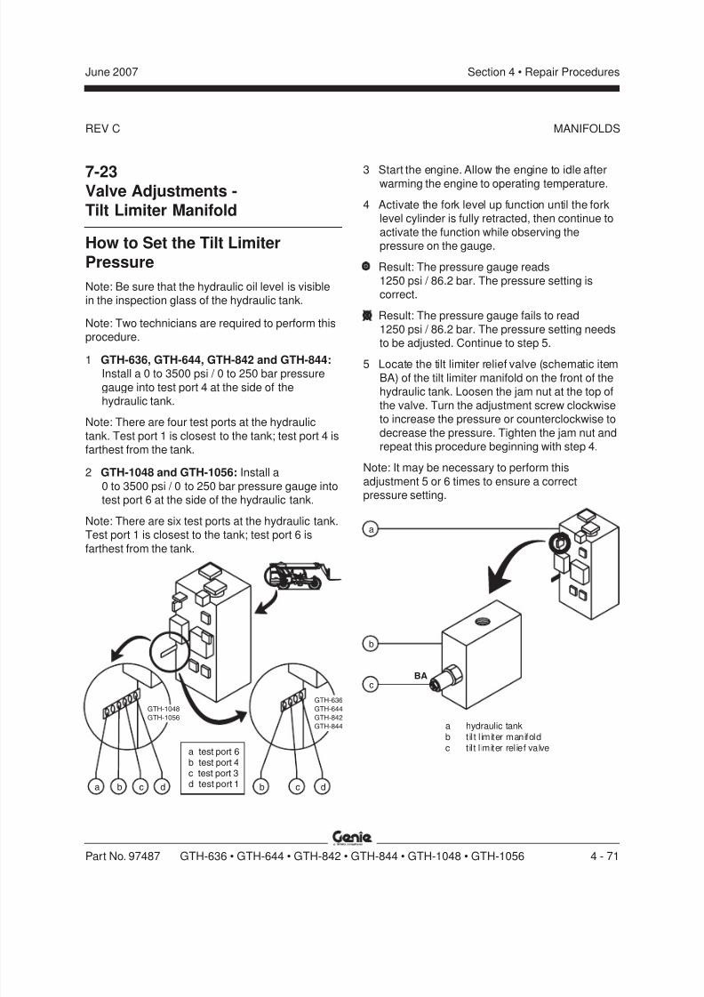
8/14/2019 Genie Manual de Servicio Gth-844
http://slidepdf.com/reader/full/genie-manual-de-servicio-gth-844 141/196
REV C
Section 4 • Repair ProceduresJune 2007
Part No. 97487 GTH-636 • GTH-644 • GTH-842 • GTH-844 • GTH-1048 • GTH-1056 4 - 71
BA
b
a
c
MANIFOLDS
7-23Valve Adjustments -Tilt Limiter Manifold
How to Set the Tilt LimiterPressure
Note: Be sure that the hydraulic oil level is visiblein the inspection glass of the hydraulic tank.
Note: Two technicians are required to perform thisprocedure.
1 GTH-636, GTH-644, GTH-842 and GTH-844:Install a 0 to 3500 psi / 0 to 250 bar pressure
gauge into test port 4 at the side of thehydraulic tank.
Note: There are four test ports at the hydraulic
tank. Test port 1 is closest to the tank; test port 4 isfarthest from the tank.
2 GTH-1048 and GTH-1056: Install a
0 to 3500 psi / 0 to 250 bar pressure gauge intotest port 6 at the side of the hydraulic tank.
Note: There are six test ports at the hydraulic tank.Test port 1 is closest to the tank; test port 6 is
farthest from the tank.
3 Start the engine. Allow the engine to idle afterwarming the engine to operating temperature.
4 Activate the fork level up function until the forklevel cylinder is fully retracted, then continue to
activate the function while observing thepressure on the gauge.
Result: The pressure gauge reads
1250 psi / 86.2 bar. The pressure setting iscorrect.
Result: The pressure gauge fails to read
1250 psi / 86.2 bar. The pressure setting needsto be adjusted. Continue to step 5.
5 Locate the tilt limiter relief valve (schematic item
BA) of the tilt limiter manifold on the front of thehydraulic tank. Loosen the jam nut at the top of
the valve. Turn the adjustment screw clockwiseto increase the pressure or counterclockwise to
decrease the pressure. Tighten the jam nut andrepeat this procedure beginning with step 4.
Note: It may be necessary to perform this
adjustment 5 or 6 times to ensure a correctpressure setting.
a hydraulic tankb til t l imiter manifoldc til t l imiter relief valve
GTH-636GTH-644
GTH-842
GTH-844
GTH-1048
GTH-1056
a b dc b dc
a 6bcd test port 1
test porttest port 4test port 3

8/14/2019 Genie Manual de Servicio Gth-844
http://slidepdf.com/reader/full/genie-manual-de-servicio-gth-844 142/196

8/14/2019 Genie Manual de Servicio Gth-844
http://slidepdf.com/reader/full/genie-manual-de-servicio-gth-844 143/196
REV D
Section 4 • Repair ProceduresJune 2007
Part No. 97487 GTH-636 • GTH-644 • GTH-842 • GTH-844 • GTH-1048 • GTH-1056 4 - 73
Axle
8-1Axles
How to Remove the Axle
Bodily injury hazard. This
procedure requires specific repairskills, lifting equipment and asuitable workshop. Attempting this
procedure without these skills andtools could result in death or
serious injury and significant
component damage. Dealerservice is required.
1 Remove the fasteners securing the driveshaft tothe transmission. Lower the end of thedriveshaft to the ground.
2 Remove the fasteners securing the driveshaft tothe axle. remove the driveshaft from the
machine.
3 Loosen the lug nuts of both wheels on the axleto be removed. Do not remove the lug nuts.
4 Raise the end of the machine until the tires are
off the ground. Place blocks under the chassisfor support.
Crushing hazard. The chassis will
fall if not properly supported.
5 Remove the lug nuts. Remove the tire andwheel assembly from both ends of the axle.
6 Support and secure the axle to an appropriatelifting device.
7 Working at one side of the machine, tag,disconnect and plug the fork level cylinderhoses at the cylinder manifold. Cap the fittings.
Bodily injury hazard. Spraying
hydraulic oil can penetrate andburn skin. Loosen hydraulic
connections very slowly to allowthe oil pressure to dissipategradually. Do not allow oil to
squirt or spray.
Component damage hazard.Hoses can be damaged if they are
kinked or pinched.
8 Attach a lifting strap from an overhead crane tothe barrel end of the axle level cylinder. Support
the cylinder. Do not apply any lifting pressure.
9 Remove the fasteners securing the axle level
cylinder barrel-end pivot pin to the chassis.
10 Use a soft metal drift to remove the pivot pin.Lower the cylinder onto the axle.
Crushing hazard. The cylinder will
fall if not properly supported whenthe pivot pin is removed from themachine.
11 Repeat this procedure, beginning with step 6,for the other side of the axle.
12 Remove the fasteners securing the axle to the
chassis. Remove the axle from the machine.
Crushing hazard. The axle will fallif not properly supported when the
fasteners are removed from themachine.
Note: When installing the axle onto the chassis,
torque the fasteners to specification.
Torque specification
Axle mounting fasteners 380 ft-lbs
515 Nm

8/14/2019 Genie Manual de Servicio Gth-844
http://slidepdf.com/reader/full/genie-manual-de-servicio-gth-844 144/196
REV D
Section 4 • Repair Procedures June 2007
4 - 74 GTH-636 • GTH-644 • GTH-842 • GTH-844 • GTH-1048 • GTH-1056 Part No. 97487
How to Adjust the Front AxleService Brakes
GTH-1048 and GTH-1056
When using the GTH-1048 and GTH-1056, most of
the braking is performed by the front axle. As aresult, the rear axle service brakes will rarely need
to be adjusted. Should adjustment of the rear axleservice brakes be required, contact the GenieIndustries Service Dept.
1 Chock the tires.
2 Start the engine and allow the engine to idle.
3 Release the parking brake.
4 At the front axle, locate and remove the coversover the service brake adjustment screws.Refer to the following illustrations.
How to Adjust the Parking BrakesGTH-636, GTH-644, GTH-842 and GTH-844
1 Chock the tires.
2 Start the engine and allow the engine to idle.
3 Release the parking brake.
4 Remove the top inspection cover from thechassis at the fork end of the machine. Locate
the parking brake cylinder on top of the driveaxle.
5 Loosen the lock nut securing the threadedportion of the parking brake adjustment rod.
6 Turn the threaded rod of the cylinder out of thecylinder several turns.
7 Turn the threaded rod into the cylinder just untilthere is zero clearance between the bushing ofthe threaded rod, the lever actuator and thelever bracket.
Note: Turning the threaded rod too far into thecylinder will move the parking brake lever, resulting
in a parking brake which does not function
correctly. Do not over tighten the rod.8 While holding the cylinder rod in position,
securely tighten the cylinder rod jam nut.
9 Inspect the parking brake lever to confirm thatthe lever is not binding or in contact with axle
casting.
10 Set the parking brake and stop the engine.
AXLE
5 Turn both of the four-sided service brake
adjustment screws in a counter clockwisedirection until a slight resistance is detected.
6 Turn both of the four-sided service brake
adjustment screws 3.75 turns in a clockwisedirection.
7 Install the covers over the service brake
adjustment screws. Securely tighten thefasteners. Do not over tighten.
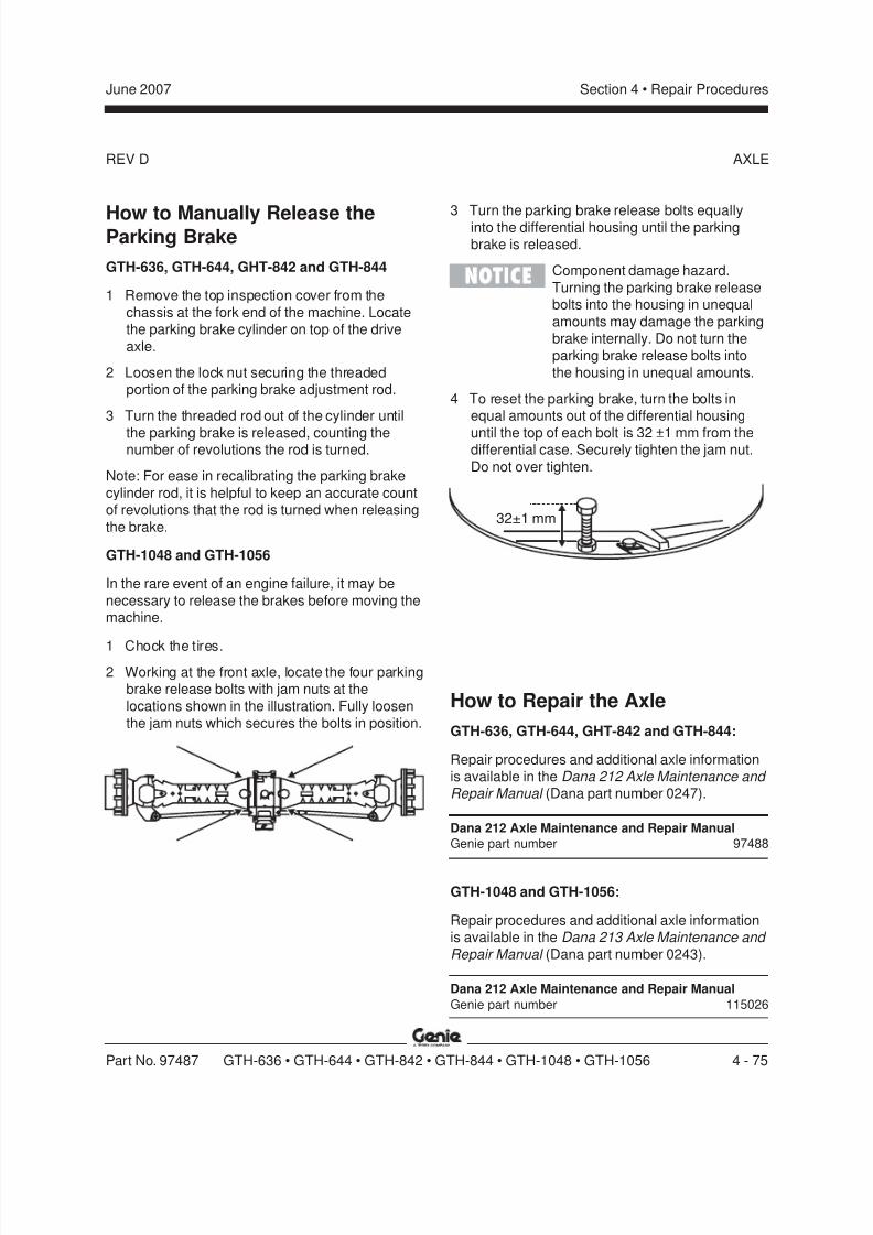
8/14/2019 Genie Manual de Servicio Gth-844
http://slidepdf.com/reader/full/genie-manual-de-servicio-gth-844 145/196
REV D
Section 4 • Repair ProceduresJune 2007
Part No. 97487 GTH-636 • GTH-644 • GTH-842 • GTH-844 • GTH-1048 • GTH-1056 4 - 75
How to Manually Release theParking Brake
GTH-636, GTH-644, GHT-842 and GTH-844
1 Remove the top inspection cover from the
chassis at the fork end of the machine. Locatethe parking brake cylinder on top of the drive
axle.
2 Loosen the lock nut securing the threadedportion of the parking brake adjustment rod.
3 Turn the threaded rod out of the cylinder until
the parking brake is released, counting thenumber of revolutions the rod is turned.
Note: For ease in recalibrating the parking brake
cylinder rod, it is helpful to keep an accurate countof revolutions that the rod is turned when releasing
the brake.
GTH-1048 and GTH-1056
In the rare event of an engine failure, it may be
necessary to release the brakes before moving themachine.
1 Chock the tires.
2 Working at the front axle, locate the four parkingbrake release bolts with jam nuts at the
locations shown in the illustration. Fully loosenthe jam nuts which secures the bolts in position.
3 Turn the parking brake release bolts equallyinto the differential housing until the parkingbrake is released.
Component damage hazard.
Turning the parking brake releasebolts into the housing in unequal
amounts may damage the parkingbrake internally. Do not turn theparking brake release bolts into
the housing in unequal amounts.
4 To reset the parking brake, turn the bolts inequal amounts out of the differential housing
until the top of each bolt is 32 ±1 mm from thedifferential case. Securely tighten the jam nut.
Do not over tighten.
32±1 mm
AXLE
How to Repair the Axle
GTH-636, GTH-644, GHT-842 and GTH-844:
Repair procedures and additional axle informationis available in the Dana 212 Axle Maintenance and Repair Manual (Dana part number 0247).
Dana 212 Axle Maintenance and Repair Manual
Genie part number 97488
GTH-1048 and GTH-1056:
Repair procedures and additional axle informationis available in the Dana 213 Axle Maintenance and
Repair Manual (Dana part number 0243).
Dana 212 Axle Maintenance and Repair Manual
Genie part number 115026

8/14/2019 Genie Manual de Servicio Gth-844
http://slidepdf.com/reader/full/genie-manual-de-servicio-gth-844 146/196
REV A
Section 4 • Repair Procedures June 2007
4 - 76 GTH-636 • GTH-644 • GTH-842 • GTH-844 • GTH-1048 • GTH-1056 Part No. 97487
9-1Outriggers
How to Remove an Outrigger
1 Extend the outrigger until the pad just touches
the ground. Do not rest the weight of themachine on the outrigger.
2 Tag, disconnect and plug the hydraulic supplyhoses at the outrigger cylinder. Cap the fittings.
Bodily injury hazard. Spraying
hydraulic oil can penetrate andburn skin. Loosen hydraulicconnections very slowly to allowthe oil pressure to dissipate
gradually. Do not allow oil tosquirt or spray.
Component damage hazard.
Hoses can be damaged if they arekinked or pinched.
3 Attach a lifting strap from an overhead crane to
the outrigger assembly. Raise the outrigger toapproximately 80°.
4 Remove the fasteners securing the outriggercylinder rod-end pivot pin to the machine.
5 Use a soft metal drift to remove the pivot pin.
Lower the cylinder onto the outrigger.
Crushing hazard. The cylindermay become unbalanced and fall
if not properly supported when thepivot pin is removed from themachine.
6 Raise the outrigger assembly to a verticalposition.
7 Remove the fasteners securing the outriggerpivot pin to the machine.
8 Use a soft metal drift to remove the pivot pin.
Remove the outrigger assembly from themachine.
Crushing hazard. The outrigger
will fall if not properly supportedwhen the pivot pin is removed
from the machine.
Outriggers

8/14/2019 Genie Manual de Servicio Gth-844
http://slidepdf.com/reader/full/genie-manual-de-servicio-gth-844 147/196
REV A
Section 4 • Repair ProceduresJune 2007
Part No. 97487 GTH-636 • GTH-644 • GTH-842 • GTH-844 • GTH-1048 • GTH-1056 4 - 77
How to Remove an OutriggerCylinder
Note: When removing a hose assembly or fitting,the O-ring on the fitting and/or hose end must bereplaced and then torqued to specification during
installation. Refer to Section 2, Hydraulic Hose and Fitting Torque Specifications.
1 Extend the outrigger until the pad just touchesthe ground. Do not rest the weight of the
machine on the outrigger.
2 Tag, disconnect and plug the two hydraulicsupply hoses at the outrigger cylinder. Cap the
fittings.
Bodily injury hazard. Sprayinghydraulic oil can penetrate and
burn skin. Loosen hydraulicconnections very slowly to allow
the oil pressure to dissipategradually. Do not allow oil to
squirt or spray.
Component damage hazard.Hoses can be damaged if they are
kinked or pinched.
3 Attach a lifting strap from an overhead crane tothe barrel end of the outrigger cylinder. Support
the cylinder. Do not apply any lifting pressure.
4 Remove the fasteners securing the outriggercylinder barrel-end pivot pin to the chassis.
5 Use a soft metal drift to remove the pivot pin.Crushing hazard. The cylinder will
fall if not properly supported whenthe pivot pin is removed from the
machine.
5 Raise the cylinder to a vertical position.
6 Remove the fasteners securing the outriggercylinder rod-end pivot pin to the machine.
7 Use a soft metal drift to remove the pivot pin.Remove the cylinder from the machine.
Crushing hazard. The cylinder willfall if not properly supported whenthe pivot pin is removed from themachine.
OUTRIGGERS

8/14/2019 Genie Manual de Servicio Gth-844
http://slidepdf.com/reader/full/genie-manual-de-servicio-gth-844 148/196
Section 4 • Repair Procedures June 2007
4 - 78 GTH-636 • GTH-644 • GTH-842 • GTH-844 • GTH-1048 • GTH-1056 Part No. 97487
This page intentionally left blank.

8/14/2019 Genie Manual de Servicio Gth-844
http://slidepdf.com/reader/full/genie-manual-de-servicio-gth-844 149/196
Section 5 TroubleshootingJune 2007
Part No. 97487 GTH-636 • GTH-644 • GTH-842 • GTH-844 • GTH-1048 • GTH-1056 5 - 1
Troubleshooting
Before Troubleshooting:Read, understand and obey the safety rules
and operating instructions in the appropriateoperator's manual on your machine.
Be sure that all necessary tools and test
equipment are available and ready for use.
Be aware of the following hazards and followgenerally accepted safe workshop practices.
Crushing hazard. When testingor replacing any hydraulic
component, always supportthe structure and secure itfrom movement.
Electrocution hazard. Contact
with electrically charged circuitscould result in death or serious
injury. Remove all rings, watchesand other jewelry.
Bodily injury hazard. Spraying
hydraulic oil can penetrate andburn skin. Loosen hydraulic
connections very slowly to allow
the oil pressure to dissipategradually. Do not allow oil to
squirt or spray.
Observe and Obey:
Troubleshooting and repair procedures shall be
completed by a person trained and qualified onthe repair of this machine.
Immediately tag and remove from service adamaged or malfunctioning machine.
Repair any machine damage or malfunctionbefore operating the machine.
Unless otherwise specified, perform eachrepair procedure with the machine in thefollowing configuration:
· Machine parked on a firm, level surface
· Boom in the stowed position
· Key switch in the off position with the keyremoved
· Wheels chocked
Malfunction
discoveredIdentify
symptomsTroubleshoot
Performrepair
Return toservice problem
solved
problemstill exists
Inspectand test
General Repair Process
8/14/2019 Genie Manual de Servicio Gth-844
http://slidepdf.com/reader/full/genie-manual-de-servicio-gth-844 150/196

8/14/2019 Genie Manual de Servicio Gth-844
http://slidepdf.com/reader/full/genie-manual-de-servicio-gth-844 151/196
REV A
Section 5 • TroubleshootingJune 2007
Part No. 97487 GTH-636 • GTH-644 • GTH-842 • GTH-844 • GTH-1048 • GTH-1056 5 - 3
TROUBLESHOOTING
How to Read the Fault CodesThe flashing BC light, when combined with short orlong pauses between the flash, tells the service
technician the specific fault coded detected by theECM, if any. Code 32, for example, would appear
as three quick flashes followed by a short pause oftwo seconds, then two more quick flashes followed
by a long pause of four seconds. Code 33 wouldappear as three quick flashes followed by a shortpause, then three more quick flashes followed by a
long pause.
Example: If the ECM had no active faults to report,though had stored codes 18 and 62 in memory, thefollowing flash sequence would be observed:
Three quick flashes followed by a short pause…two quick flashes followed by a long pause… eight
quick flashes followed by a short pause… eightquick flashes followed by a long pause… three
quick flashes followed by a short pause… threequick flashes followed by a long pause... one quickflash followed by a short pause… eight quick
flashes followed by a long pause… six quickflashes followed by a short pause… two quick
flashes followed by a long pause… the ECM wouldthen repeat the previous sequence.
Code and Description
11 Analog throttle input high12 Analog throttle input low18 Engine coolant temperature high19 Engine coolant temperature low21 Sensor supply voltage high22 Sensor supply voltage low23 Engine oil pressure input voltage high24 Engine oil pressure input voltage low
25 Manifold air temperature input voltage high26 Manifold air temperature input voltage low28 ECM error32 Signifies start of active fault codes33 Signifies start of previously active fault codes37 Fuel temperature input voltage high38 Fuel temperature input voltage low39 Crank position input noise/pattern error42 Engine overspeed54 ECM power down error55 Can error
62 Engine coolant temperature high – least severe
Code and Description
63 Engine coolant temp high – moderately severe64 Engine oil pressure moderately low65 Engine oil pressure extremely low66 Manifold air temperature moderately high68 Fuel derate69 Engine coolant temperature high – most severe71 Pump control valve closure too long72 Pump control valve closure too short
73 Pump solenoid circuit open74 Pump solenoid circuit severely shorted75 Pump control valve closure not detected76 Pump solenoid circuit moderately shorted77 Pump solenoid current high78 Security violation79 Internal ECM error81 Fuel temperature moderately high82 Engine protection shutdown83 Auxiliary engine shutdown switch active84 ECM power down error/external derate active
88 Signifies that no fault codes are stored
8/14/2019 Genie Manual de Servicio Gth-844
http://slidepdf.com/reader/full/genie-manual-de-servicio-gth-844 152/196
REV A
Section 5 • Troubleshooting June 2007
5 - 4 GTH-636 • GTH-644 • GTH-842 • GTH-844 • GTH-1048 • GTH-1056 Part No. 97487
1-2Hydraulic Pump
Symptom:Laboring engine; pump is constantly trying to buildpressure.
Check the Pump
1 Tag, disconnect and plug the smaller JIC hoseat the top of the hydraulic pump.
Bodily injury hazard. Spraying
hydraulic oil can penetrate andburn skin. Loosen hydraulic
connections very slowly to allowthe oil pressure to dissipate
gradually. Do not allow oil tosquirt or spray.
2 Install a hose onto the open port and tighten.
Place open end of hose into 5 gallon container.
3 Start the engine and run for 1 minute.
4 Stop the engine. Measure the fluid.
Result: Fluid volume is one gallon or less. The
pump is good. Proceed to step 5.
Result: Fluid volume is greater than one gallon.The pump is faulty. Replace the pump.
Check the Main Valve5 Tag and disconnect the 1.5 inch main valve
hose from the collector manifold at the top of
the hydraulic tank. Drain the hose into acontainer.
6 Place open end of hose into 5 gallon container.
7 Start the engine.
Result: No fluid is draining from the hose. Themain valve is good. Proceed to step 10.
Result: Fluid is draining from the hose. Inspect
the main valve Y-plug. Proceed to the nextstep.
8 Stop the engine. Remove the Y-plug from the
top of the main valve. Inspect for cracks, cutsor breaks in the o-ring or teflon ring.
Result: Cracks, cuts or breaks are not
observed. The Y-plug is in good condition.Proceed to the next step.
Result: Cracks, cuts or breaks are observed.
Replace the o-ring or teflon ring.
Bodily injury hazard. Spraying
hydraulic oil can penetrate andburn skin. Loosen hydraulicconnections very slowly to allow
the oil pressure to dissipategradually. Do not allow oil to
squirt or spray.
9 Remove the manifold relief valve (schematicitem AD) from the main valve manifold. Inspect
for cracks, cuts or breaks in the seals.
Result: Cracks, cuts or breaks are notobserved. Replace the relief valve.
Result: Cracks, cuts or breaks are observed.Replace the seals.
Bodily injury hazard. Sprayinghydraulic oil can penetrate and
burn skin. Loosen hydraulicconnections very slowly to allow
the oil pressure to dissipategradually. Do not allow oil to
squirt or spray.
TROUBLESHOOTING
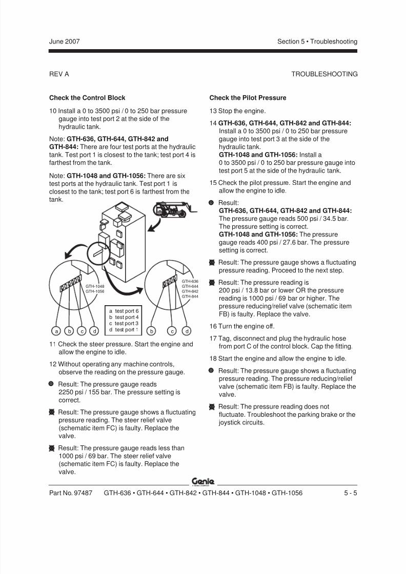
8/14/2019 Genie Manual de Servicio Gth-844
http://slidepdf.com/reader/full/genie-manual-de-servicio-gth-844 153/196
REV A
Section 5 • TroubleshootingJune 2007
Part No. 97487 GTH-636 • GTH-644 • GTH-842 • GTH-844 • GTH-1048 • GTH-1056 5 - 5
Check the Control Block10 Install a 0 to 3500 psi / 0 to 250 bar pressure
gauge into test port 2 at the side of the
hydraulic tank.
Note: GTH-636, GTH-644, GTH-842 andGTH-844: There are four test ports at the hydraulic
tank. Test port 1 is closest to the tank; test port 4 isfarthest from the tank.
Note: GTH-1048 and GTH-1056: There are sixtest ports at the hydraulic tank. Test port 1 is
closest to the tank; test port 6 is farthest from the
tank.
Check the Pilot Pressure13 Stop the engine.
14 GTH-636, GTH-644, GTH-842 and GTH-844:Install a 0 to 3500 psi / 0 to 250 bar pressure
gauge into test port 3 at the side of thehydraulic tank.
GTH-1048 and GTH-1056: Install a0 to 3500 psi / 0 to 250 bar pressure gauge into
test port 5 at the side of the hydraulic tank.
15 Check the pilot pressure. Start the engine andallow the engine to idle.
Result:GTH-636, GTH-644, GTH-842 and GTH-844:The pressure gauge reads 500 psi / 34.5 bar.
The pressure setting is correct.GTH-1048 and GTH-1056: The pressure
gauge reads 400 psi / 27.6 bar. The pressuresetting is correct.
Result: The pressure gauge shows a fluctuating
pressure reading. Proceed to the next step.
Result: The pressure reading is200 psi / 13.8 bar or lower OR the pressure
reading is 1000 psi / 69 bar or higher. Thepressure reducing/relief valve (schematic item
FB) is faulty. Replace the valve.
16 Turn the engine off.
17 Tag, disconnect and plug the hydraulic hosefrom port C of the control block. Cap the fitting.
18 Start the engine and allow the engine to idle.
Result: The pressure gauge shows a fluctuatingpressure reading. The pressure reducing/reliefvalve (schematic item FB) is faulty. Replace the
valve.
Result: The pressure reading does not
fluctuate. Troubleshoot the parking brake or the joystick circuits.
TROUBLESHOOTING
11 Check the steer pressure. Start the engine andallow the engine to idle.
12 Without operating any machine controls,
observe the reading on the pressure gauge.
Result: The pressure gauge reads2250 psi / 155 bar. The pressure setting is
correct.Result: The pressure gauge shows a fluctuatingpressure reading. The steer relief valve
(schematic item FC) is faulty. Replace thevalve.
Result: The pressure gauge reads less than
1000 psi / 69 bar. The steer relief valve(schematic item FC) is faulty. Replace the
valve.
GTH-636
GTH-644
GTH-842
GTH-844
GTH-1048
GTH-1056
a b dc b dc
a 6bc
d test port 1
test port
test port 4test port 3

8/14/2019 Genie Manual de Servicio Gth-844
http://slidepdf.com/reader/full/genie-manual-de-servicio-gth-844 154/196
REV B
Section 5 • Troubleshooting June 2007
5 - 6 GTH-636 • GTH-644 • GTH-842 • GTH-844 • GTH-1048 • GTH-1056 Part No. 97487
1-3Boom Functions
Joystick (4-way) Circuit
Symptom:
Slow or no boom functions
Check the Pilot Pressure
1 GTH-636, GTH-644, GTH-842 and GTH-844:Install a 0 to 3500 psi / 0 to 250 bar pressure
gauge into test port 3 at the side of the
hydraulic tank.
Note: There are four test ports at the hydraulic
tank. Test port 1 is closest to the tank; test port 4 isfarthest from the tank.
2 GTH-1048 and GTH-1056: Install a0 to 3500 psi / 0 to 250 bar pressure gauge into
test port 5 at the side of the hydraulic tank.
Note: There are six test ports at the hydraulic tank.Test port 1 is closest to the tank; test port 6 is
farthest from the tank.
3 Check the pilot pressure. Start the engine andallow the engine to idle.
Result:GTH-636, GTH-644, GTH-842 and GTH-844:
The pressure gauge reads 500 psi / 34.5 bar.The pressure setting is correct. Proceed to step
4.GTH-1048 and GTH-1056: The pressuregauge reads 400 psi / 27.6 bar. The pressure
setting is correct. Proceed to step 4.
Result:GTH-636, GTH-644, GTH-842 and GTH-844:
The pressure gauge fails to read500 psi / 34.5 bar. Adjust or replace the
pressure reducing/relief valve (schematic itemFB). Refer to Repair Procedure 7-18, How to
Set the Boom System Pilot Pressure.GTH-1048 and GTH-1056: The pressuregauge fails to read 400 psi / 27.6 bar. Adjust or
replace the pressure reducing/relief valve(schematic item FB). Refer to Repair Procedure
7-18, How to Set the Boom System Pilot Pressure.
Result: The pressure reading is
200 psi / 13.8 bar or lower. The pressurereducing/relief valve (schematic item FB) is
faulty. Replace the valve.
4 GTH-636, GTH-1048 and GTH-1056: Stop theengine. Proceed to step 5.
GTH-644, GTH-842 and GTH-844: Stop theengine. Proceed to step 13.
TROUBLESHOOTING
GTH-636
GTH-644
GTH-842
GTH-844
GTH-1048
GTH-1056
a b dc b dc
a 6b
cd test port 1
test porttest port 4test port 3
8/14/2019 Genie Manual de Servicio Gth-844
http://slidepdf.com/reader/full/genie-manual-de-servicio-gth-844 155/196
REV B
Section 5 • TroubleshootingJune 2007
Part No. 97487 GTH-636 • GTH-644 • GTH-842 • GTH-844 • GTH-1048 • GTH-1056 5 - 7
Check the Controller Relief (drop block)Manifold
5 Turn the key switch to the on position. Do not
start the engine.
6 Using a wrench, check for magnetism in thesolenoid valve of the controller relief manifold.
Touch a wrench to the end of the valve.
Result: The wrench sticks to the valve. The coilis good. Proceed to step 9.
Result: The wrench does not stick to the valve.Proceed to step 7.
Note: The controller relief manifold is secured to
the hoses inside the frame rail next to theoperator's compartment.
Note: A fast way to determine if a valve coil isfunctioning correctly is to touch a wrench to the
end of the valve when the coil is activated. Whenenergized, the valve will magnetize and the wrenchwill stick to the valve; turn the power off and the
wrench will fall.
7 Using a multimeter, check for power at thevalve coil.
Result: Power is present at the coil. Proceed to
step 8.
Result: Power is not present at the coil. Repairthe wire circuit to the coil.
8 Check for continuity in the ground wire circuit
from the controller relief valve coil to ground.
Result: The ground circuit has continuity.Replace the valve coil.
Result: The ground circuit does not havecontinuity. Repair the ground wire circuit to the
coil.
9 Tag and disconnect the two smaller hydraulichoses at the controller relief manifold. Connectthe hoses together and torque to specification.Refer to Section 2, Specifications .
Note: Do not remove the three larger hoses fromthe manifold.
10 Start the engine and allow the engine to idle.Test a boom function.
Result: The boom functions correctly. The
controller relief valve (schematic item OA) isfaulty. Replace the valve.
Result: The boom does not function correctly.The controller relief valve is good. Proceed tostep 11.
11 Stop the engine.
12 Install the hoses, disconnected in step 9, intothe controller relief manifold. Torque to
specification. Refer to Section 2, Specifications .
Check the Joystick
13 Locate the hose installed into port P of the joystick. Tag the hose.
14 Tag, disconnect and plug all hydraulic hosesinstalled into the joystick except for the hose atport P of the joystick.
15 Start the engine and allow the engine to idle. Do
not move the joystick.
Result: Oil does not flow from any port. The joystick is functioning correctly.
Result: Oil flows from one or more ports of the joystick. The joystick is faulty. Repair or replace
the joystick.
TROUBLESHOOTING

8/14/2019 Genie Manual de Servicio Gth-844
http://slidepdf.com/reader/full/genie-manual-de-servicio-gth-844 156/196
REV B
Section 5 • Troubleshooting June 2007
5 - 8 GTH-636 • GTH-644 • GTH-842 • GTH-844 • GTH-1048 • GTH-1056 Part No. 97487
Check the Tilt Function16 Stop the engine.
17 Turn the key switch to the on position. Do notstart the engine.
18 Locate the control relay under the joystick.Check the relay for functionality.
Note: A fast way to determine if a relay is
functioning correctly is to listen carefully whenactivating the relay. When activated, the relay will
make a distinctive 'click' as the relay contactsswitch internally.
19 Activate the fork level functions and, using awrench, check for magnetism in the solenoid
valves of both fork tilt manifolds (schematicitems GA and GB). Touch a wrench to the endof the valve.
Result: The wrench sticks to the valve. The coilis good. Replace the valve(s).
Result: The wrench does not stick to the
valve(s). Proceed to step 20.
Note: The fork tilt manifolds are the two manifolds
on the hydraulic tank located closest to the bottomof the tank.
Note: A fast way to determine if a valve coil is
functioning correctly is to touch a wrench to theend of the valve when the coil is activated. When
energized, the valve will magnetize and the wrenchwill stick to the valve; turn the power off and the
wrench will fall.
20 Using a multimeter, check for power at thevalve coils.
Result: Power is present at the coils. Proceed tostep 21.
Result: Power is not present at the coil(s).
Repair the wire circuit to the coil(s).
21 Check for continuity in the ground wire circuitfrom the fork tilt valve coils to ground.
Result: The ground circuit has continuity.Replace the valve coil(s).
Result: The ground circuit does not havecontinuity. Repair the ground wire circuit to thecoil(s).
TROUBLESHOOTING
8/14/2019 Genie Manual de Servicio Gth-844
http://slidepdf.com/reader/full/genie-manual-de-servicio-gth-844 157/196
REV B
Section 5 • TroubleshootingJune 2007
Part No. 97487 GTH-636 • GTH-644 • GTH-842 • GTH-844 • GTH-1048 • GTH-1056 5 - 9
Lift Not Functional1 Tag and disconnect the hydraulic hoses at the
dual pilot check manifold. Cap the fittings on the
manifold. Connect together both hoses from theCA side of the manifold AND connect togetherboth hoses from the CB side of the manifold.
Torque to specification. Refer to Section 2,Specifications .
Bodily injury hazard. Sprayinghydraulic oil can penetrate andburn skin. Loosen hydraulic
connections very slowly to allowthe oil pressure to dissipate
gradually. Do not allow oil tosquirt or spray.
2 Start the engine and allow the engine to idle.
3 Activate the boom up function.
Result: The machine functions correctly.Replace the check valves of the dual pilot
check valve manifold (schematic items CA andCB) OR replace the dual pilot check valvemanifold.
Result: The machine does not functioncorrectly. Proceed to step 4.
Crushing Hazard. The load on theforks could fall when lowering the
boom due to bypassing the forkself-leveling function, resulting in
death or serious injury andproperty damage. Do not allow
anyone to stand anywhere nearthe area below or in front of the
boom when performing thisprocedure.
TROUBLESHOOTING
4 Lower the boom to the stowed position. Stopthe engine.
5 Replace the check valve at the barrel end of thefork level cylinder (schematic item RA) OR
troubleshoot the dual pilot check circuit.
Bodily injury hazard. Sprayinghydraulic oil can penetrate and
burn skin. Loosen hydraulicconnections very slowly to allow
the oil pressure to dissipategradually. Do not allow oil tosquirt or spray.
8/14/2019 Genie Manual de Servicio Gth-844
http://slidepdf.com/reader/full/genie-manual-de-servicio-gth-844 158/196
REV B
Section 5 • Troubleshooting June 2007
5 - 10 GTH-636 • GTH-644 • GTH-842 • GTH-844 • GTH-1048 • GTH-1056 Part No. 97487
Fork Rotate FunctionSymptom:Fork rotates in one direction only (if equipped).
1 Turn the key switch to the on position. Start theengine.
2 Operate the manual over ride at both ends of
the fork rotate valve.
Result: The machine functions correctly.
Proceed to step 3.
Result: The machine does not function
correctly. Remove air from the fork rotatecircuit. Refer to Repair Procedure 1-6, How to Replace the Fork Rotate Cylinder Hoses .
3 Troubleshoot the fork rotate electrical circuit.
While activating the fork rotate function in onedirection, use a wrench to check for magnetismin the solenoid valve of the fork rotate manifold.
Touch a wrench to the valve.
Result: The wrench sticks to the valve. The coil
is good.
Result: The wrench does not stick to the valve.
Repair or replace the wire circuit from the forktilt switch to the fork tilt valve coil OR replacethe fork tilt switch OR replace the valve coil.
Note: A fast way to determine if a valve coil isfunctioning correctly is to touch a wrench to the
end of the valve when the coil is activated. Whenenergized, the valve will magnetize and the wrench
will stick to the valve; turn the power off and thewrench will fall.
4 Activate the fork rotate switch in the oppositedirection from step 3 and use a wrench tocheck for magnetism in the solenoid valve ofthe fork rotate manifold. Touch a wrench to the
valve.
Result: The wrench sticks to the valve. The coil
is good. Replace the valve (schematic item LA).
Result: The wrench does not stick to the valve.Repair or replace the wire circuit from the fork
tilt switch to the fork tilt valve coil OR replacethe fork tilt switch OR replace the valve coil.
TROUBLESHOOTING
8/14/2019 Genie Manual de Servicio Gth-844
http://slidepdf.com/reader/full/genie-manual-de-servicio-gth-844 159/196
REV B
Section 5 • TroubleshootingJune 2007
Part No. 97487 GTH-636 • GTH-644 • GTH-842 • GTH-844 • GTH-1048 • GTH-1056 5 - 11
Fork Level FunctionSymptom A:Forks self-level at slower rate than boom is
descending
Check the Tilt Relief Valve
1 Start the engine and allow the engine to idle.
2 Level the forks.
3 Stop the engine.
4 Tag and disconnect the hydraulic hoses at the
tilt limiter manifold. Cap the fittings on themanifold. Connect the hoses together and
torque to specification. Refer to Section 2,Specifications .
Bodily injury hazard. Spraying
hydraulic oil can penetrate andburn skin. Loosen hydraulic
connections very slowly to allowthe oil pressure to dissipate
gradually. Do not allow oil tosquirt or spray.
5 Start the engine and allow the engine to idle.
6 Activate the boom up and boom down
functions.
Result: The machine functions correctly.Replace the relief valve of the tilt limiter
manifold (schematic item BA).
Result: The machine does not functioncorrectly. Troubleshoot the fork level cylinder
manifold components (schematic items RA, RBand RC) OR check the cylinder for internal
leakage.
Symptom B:Forks self-level at a faster rate than the boom isdescending.
1 Remove the load from the forks.
2 Start the engine and allow the engine to idle.
3 Level the forks.
4 Stop the engine.
5 Tag and disconnect the two hydraulic hoses of
the boom from the tee fittings at ports C1 andC2 of the dual pilot check manifold. Cap the
fittings.Bodily injury hazard. Sprayinghydraulic oil can penetrate and
burn skin. Loosen hydraulicconnections very slowly to allow
the oil pressure to dissipategradually. Do not allow oil to
squirt or spray.
6 Tag and disconnect the hydraulic hoses fromthe fittings at ports V1 and V2 of the dual pilot
check manifold. Cap the fittings.
Bodily injury hazard. Sprayinghydraulic oil can penetrate and
burn skin. Loosen hydraulicconnections very slowly to allowthe oil pressure to dissipate
gradually. Do not allow oil tosquirt or spray.
7 Connect the hydraulic hose of port C1 to the
hydraulic hose of port V1. Torque tospecification. Refer to Section 2, Specifications .
8 Connect the hydraulic hose of port C2 to the
hydraulic hose of port V2. Torque to
specification. Refer to Section 2, Specifications .
9 Start the engine and allow the engine to idle.
TROUBLESHOOTING
8/14/2019 Genie Manual de Servicio Gth-844
http://slidepdf.com/reader/full/genie-manual-de-servicio-gth-844 160/196
REV B
Section 5 • Troubleshooting June 2007
5 - 12 GTH-636 • GTH-644 • GTH-842 • GTH-844 • GTH-1048 • GTH-1056 Part No. 97487
10 Activate the boom up and boom downfunctions.
Result: The machine functions correctly.Replace the check valves of the dual pilot
check manifold (schematic items CA and CB).
Result: The machine does not functioncorrectly. Proceed to step 11.
11 Separate the hoses connected together in steps
7 and 8, and install them into the correct portsof the dual pilot check manifold. Torque to
specification. Refer to Section 2, Specifications .
Bodily injury hazard. Sprayinghydraulic oil can penetrate and
burn skin. Loosen hydraulicconnections very slowly to allow
the oil pressure to dissipategradually. Do not allow oil to
squirt or spray.
12 Start the engine and allow the engine to idle.
13 Lower the boom to the stowed position.
14 Stop the engine.
15 Tag and disconnect the lower supply hose to
the lift cylinder at the exhaust side of themachine.
Bodily injury hazard. Spraying
hydraulic oil can penetrate andburn skin. Loosen hydraulicconnections very slowly to allow
the oil pressure to dissipategradually. Do not allow oil to
squirt or spray.
16 Start the engine and allow the engine to idle.
17 Activate the boom down function.
Result: Fluid is leaking from the open port of the
cylinder. The cylinder has internal leakage.Replace the seals inside the cylinder.
Fork Level Hose Blowout1 Remove the load from the forks.
2 Tag and disconnect the hydraulic hoses fromthe boom at ports C1 and C2 of the dual pilot
check manifold. Plug the hoses.
3 Using a jumper hose, connect together ports C1and C2 and torque to specification. Refer to
Section 2, Specifications .
Bodily injury hazard. Sprayinghydraulic oil can penetrate and
burn skin. Loosen hydraulicconnections very slowly to allow
the oil pressure to dissipategradually. Do not allow oil to
squirt or spray.
4 Start the engine and allow the engine to idle.
5 Activate the boom down function and lower theboom to the stowed position.
Note: Once the hoses are replaced, the circuit
must be bled. Refer to Repair Procedure 1-3, How to Bleed the Lift/Tilt Circuit .
TROUBLESHOOTING

8/14/2019 Genie Manual de Servicio Gth-844
http://slidepdf.com/reader/full/genie-manual-de-servicio-gth-844 161/196
8/14/2019 Genie Manual de Servicio Gth-844
http://slidepdf.com/reader/full/genie-manual-de-servicio-gth-844 162/196
REV A
Section 5 • Troubleshooting June 2007
5 - 14 GTH-636 • GTH-644 • GTH-842 • GTH-844 • GTH-1048 • GTH-1056 Part No. 97487
1-5Steer Functions
How to Troubleshoot the Steering
Check the Steer Orbitral
1 Tag, disconnect and plug the hoses at orbitralports T, R and L. Do not cap the fittings.
Bodily injury hazard. Spraying
hydraulic oil can penetrate andburn skin. Loosen hydraulic
connections very slowly to allowthe oil pressure to dissipate
gradually. Do not allow oil tosquirt or spray.
2 Install the hose from port P into port L and
torque to specification. Refer to Section 2,Specifications .
3 Start the engine. Do not move the steering
wheel.
Result: There is no flow from the open ports ofthe orbitral. The steer orbitral is functioning
correctly.Result: There is fluid flow from one or more ofthe ports of the orbitral. The steer orbitral is
faulty and must be repaired or replaced.
4 Turn the machine off. Install the hoses onto thecorrect orbitral fitting and torque to
specification. Refer to Section 2, Specifications .
Check the Steer Selector Valve5 Start the engine.
Result: The wheels at one or both ends of themachine 'drift' after releasing the steering
wheel.
6 Adjust the wheels so that all wheels are parallel
with the length of the chassis.
7 Turn off the engine.
8 Working inside the operator's compartment,remove the fasteners securing the joystick
inspection cover to the side console.9 Remove the fasteners securing the steer
selector to the side console.
10 Tag and disconnect the hoses from the steerselector valve. Cap the fittings on the valve.
Bodily injury hazard. Sprayinghydraulic oil can penetrate andburn skin. Loosen hydraulicconnections very slowly to allow
the oil pressure to dissipategradually. Do not allow oil to
squirt or spray.11 Connect together the hoses from port EXH and
CYL 1, and torque to specification. Refer to
Section 2, Specifications .
12 Connect together the hoses from port PSI and
CYL 2, and torque to specification. Refer to
Section 2, Specifications .
13 Start the engine.
TROUBLESHOOTING
8/14/2019 Genie Manual de Servicio Gth-844
http://slidepdf.com/reader/full/genie-manual-de-servicio-gth-844 163/196
8/14/2019 Genie Manual de Servicio Gth-844
http://slidepdf.com/reader/full/genie-manual-de-servicio-gth-844 164/196
REV A
Section 5 • Troubleshooting June 2007
5 - 16 GTH-636 • GTH-644 • GTH-842 • GTH-844 • GTH-1048 • GTH-1056 Part No. 97487
Check the Rear Steer Cylinder32 Start the engine.
33 Move the steer selector to oblique steer.
34 Turn the steering wheel to the right until the
wheels turn fully to the right, then turn themachine off.
35 Tag, disconnect and plug the return hose at the
cylinder. Do not cap the fitting.
36 Start the engine.
37 Turn the steering wheel to the right, then turn
the machine off.
Result: Fluid does not flow from the open fittingon the steer cylinder. The cylinder is operating
correctly.
Result: Fluid flows from the open fitting on thesteer cylinder. The cylinder is faulty and mustbe repaired or replaced.
38 Install the hose, disconnected in step 35, ontothe cylinder and torque to specification. Refer to
Section 2, Specifications .
39 Start the engine.40 Turn the steering wheel to the left until the
wheels turn fully to the left, then turn the
machine off.
41 Tag, disconnect and plug the return hose at thecylinder. Do not cap the fitting.
42 Start the engine.
43 Turn the steering wheel to the left, then turn themachine off.
Result: Fluid does not flow from the open fittingon the steer cylinder. The cylinder is operating
correctly.
Result: Fluid flows from the open fitting on thesteer cylinder. The cylinder is faulty and must
be repaired or replaced.
44 Install the hose, disconnected in step 41, ontothe cylinder and torque to specification. Refer to
Section 2, Specifications .
TROUBLESHOOTING
8/14/2019 Genie Manual de Servicio Gth-844
http://slidepdf.com/reader/full/genie-manual-de-servicio-gth-844 165/196
REV A
Section 5 • TroubleshootingJune 2007
Part No. 97487 GTH-636 • GTH-644 • GTH-842 • GTH-844 • GTH-1048 • GTH-1056 5 - 17
1-6Brake Functions
Service Brakes
Symptom:
Brakes dragging (not releasing)
1 Tee in a 0 to 1000 psi / 0 to 100 bar pressure
gauge at port A of the brake actuator at thebrake pedal assembly.
2 Start the engine and allow the engine to idle. Do
not touch the brake pedal.
Result: The gauge indicates 0 psi / 0 bar. Theactuator is good.
Result: The gauge indicates more than
0 psi / 0 bar. The actuator is faulty. Replace thebrake actuator.
Symptom:
Brakes slow to apply OR apply too quickly
1 Tee in a 0 to 1000 psi / 0 to 100 bar pressuregauge at port A of the brake actuator at the
brake pedal assembly.
2 Start the engine and allow the engine to idle.
3 Press down on the brake pedal.
Result: The gauge indicates600 to 650 psi / 41.4 to 44.8 bar. The actuator
is good.
Result: The gauge indicates less than600 psi / 41.4 bar. The actuator is faulty.
Replace the brake actuator.
Result: The gauge indicates more than650 psi / 44.8 bar. The actuator is faulty.
Replace the brake actuator.
Parking BrakeSymptom:Parking brake does not hold OR does not release
1 Locate the parking brake manifold.
Note: The parking brake manifold is the outboardof the two manifolds located inside the frame rail
next to the operator's compartment.
2 Tag, disconnect and plug the hydraulic hoses atports 1 and 2 of the parking brake manifold.
Cap the fittings.
Bodily injury hazard. Sprayinghydraulic oil can penetrate andburn skin. Loosen hydraulic
connections very slowly to allowthe oil pressure to dissipate
gradually. Do not allow oil tosquirt or spray.
3 Install a hose measuring 3 feet / 1 m into each
port and tighten.
4 With the open ends of both hoses into a 5gallon container, start the engine.
TROUBLESHOOTING
8/14/2019 Genie Manual de Servicio Gth-844
http://slidepdf.com/reader/full/genie-manual-de-servicio-gth-844 166/196
REV A
Section 5 • Troubleshooting June 2007
5 - 18 GTH-636 • GTH-644 • GTH-842 • GTH-844 • GTH-1048 • GTH-1056 Part No. 97487
1-7Sway Functions
Symptom:When activating the sway function, the rear axlewon’t move.
Check the Boom Angle Limit Switch
The GTH-636 is not equipped witha boom angle limit switch. To
troubleshoot the sway function ona GTH-636, begin this procedure
with step 7.
1 Remove all weight from the forks.
2 GTH-1056: Lower the boom to below 55°. Turnthe machine off.
All other models: Lower the boom to below60°. Turn the machine off.
3 Turn the key switch to the on position. Do not
start the engine.
Parking brake does not hold:5 Activate the parking brake (parking brake on).
Result: Oil passes through port 2 and does notpass through port 1. The manifold is functioning
correctly.
Result: Oil passes through port 1 and does not
pass through port 2. The manifold is faulty.Replace the manifold (schematic item IA).
Parking brake does not release:
6 Deactivate the parking brake (parking brake
off).
Result: Oil passes through port 1 and does not
pass through port 2. The manifold is functioningcorrectly. The pilot pressure setting is too low.
Calibrate the pilot pressure.
Result: Oil passes through port 2 and does notpass through port 1. The manifold is faulty.
Replace the manifold (schematic item IA).
Note: Required maintenance procedures andadditional axle information is available in the Dana
212 Axle Maintenance and Repair Manual
(Dana part number MO212S20) OR theDana 213 Axle Maintenance and Repair Manual (Dana part number 0243).
Dana 212 Axle Maintenance and Repair Manual
(GTH-636, GTH-644, GTH-842 and GTH-844)
Genie part number 97488
Dana 213 Axle Maintenance and Repair Manual
(GTH-1048 and GTH-1056)
Genie part number 115026
TROUBLESHOOTING

8/14/2019 Genie Manual de Servicio Gth-844
http://slidepdf.com/reader/full/genie-manual-de-servicio-gth-844 167/196
REV A
Section 5 • TroubleshootingJune 2007
Part No. 97487 GTH-636 • GTH-644 • GTH-842 • GTH-844 • GTH-1048 • GTH-1056 5 - 19
4 Using a wrench, check for magnetism in thesolenoid valve of the boom activated rearlock-up manifold. Touch a wrench to the end ofthe valve.
Result: The wrench sticks to the valve. Theboom angle limit switch wiring is reversed OR
the switch is faulty. Proceed to step 5.
Result: The wrench does not stick to the valve.The wiring is functioning correctly. Proceed to
step 7.
Note: The boom activated rear lock-up manifold ismounted on the hydraulic tank and is located
closest to the top of the tank at the cab side of themachine.
Note: A fast way to determine if a valve coil isfunctioning correctly is to touch a wrench to the
end of the valve when the coil is activated. Whenenergized, the valve will magnetize and the wrenchwill stick to the valve; turn the power off and the
wrench will fall.
5 Confirm that the yellow wire of the limit switchwire harness is attached to the center terminal
of the limit switch, and that the grey wire of the
limit switch wire harness is attached to theterminal closest to the roller arm.
TROUBLESHOOTING
6 Using a multimeter, check for power at theterminal closest to the roller arm of the limitswitch (grey wire).
Result: Power is not present at the terminal.
The switch is functioning correctly. Repair orreplace the grey wire of the limit switch wire
harness from the limit switch to the boomactivated rear lock-up valve coil.
Result: Power is present at the terminal. The
limit switch is not calibrated correctly OR thelimit switch is faulty. Calibrate the switch ORreplace and calibrate the switch.
Check the Rear Lock-up Valve
7 Tag and disconnect the hydraulic hoses from
ports 1 and 2 of the boom activated rear lock-up manifold. Connect the hoses together and
torque to specification. Refer to Section 2,Specifications .
Bodily injury hazard. Spraying
hydraulic oil can penetrate andburn skin. Loosen hydraulicconnections very slowly to allow
the oil pressure to dissipate
gradually. Do not allow oil tosquirt or spray.
8 Start the engine and allow the engine to idle.
9 Activate the sway function.
Result: The machine functions correctly. Repair
or replace the boom activated rear lock-upvalve (schematic item DA).
Result: The machine does not function
correctly. Proceed to step 10.

8/14/2019 Genie Manual de Servicio Gth-844
http://slidepdf.com/reader/full/genie-manual-de-servicio-gth-844 168/196
REV A
Section 5 • Troubleshooting June 2007
5 - 20 GTH-636 • GTH-644 • GTH-842 • GTH-844 • GTH-1048 • GTH-1056 Part No. 97487
10 Stop the engine.11 Separate the hoses connected together in step
7, and install them into the correct ports of theboom activated rear lock-up manifold. Torque
to specification. Refer to Section 2,Specifications .
Bodily injury hazard. Spraying
hydraulic oil can penetrate andburn skin. Loosen hydraulic
connections very slowly to allowthe oil pressure to dissipategradually. Do not allow oil to
squirt or spray.
Check the Rear Lock-up Manifold
12 Tee in a 0 to 3500 psi / 0 to 250 bar pressuregauge at port P of the boom activated rear
lock-up manifold. Torque to specification. Referto Section 2, Specifications .
Bodily injury hazard. Spraying
hydraulic oil can penetrate andburn skin. Loosen hydraulicconnections very slowly to allow
the oil pressure to dissipate
gradually. Do not allow oil tosquirt or spray.
13 Start the engine and allow the engine to idle.Result:
GTH-644, GTH-842 and GTH-844 andGTH-1056: The pressure gauge reads
3000 psi / 207 bar. The pressure setting iscorrect. Proceed to step 14.GTH-1048: The pressure gauge reads3500 psi / 241 bar. The pressure setting iscorrect. Proceed to step 14.
Result: The pressure is low. There is blockagein the hoses. Troubleshoot the hoses untilblockage is found.
14 Stop the engine.
15 Tee in a 0 to 3500 psi / 0 to 250 bar pressuregauge at port C1 of the boom activated rear
lock-up manifold. Torque to specification. Referto Section 2, Specifications .
Bodily injury hazard. Sprayinghydraulic oil can penetrate andburn skin. Loosen hydraulic
connections very slowly to allowthe oil pressure to dissipategradually. Do not allow oil to
squirt or spray.
TROUBLESHOOTING

8/14/2019 Genie Manual de Servicio Gth-844
http://slidepdf.com/reader/full/genie-manual-de-servicio-gth-844 169/196
REV A
Section 5 • TroubleshootingJune 2007
Part No. 97487 GTH-636 • GTH-644 • GTH-842 • GTH-844 • GTH-1048 • GTH-1056 5 - 21
TROUBLESHOOTING
16 Start the engine and allow the engine to idle.Result: The pressure gauge is reads
500 psi / 34.5 bar. The pressure setting iscorrect. Proceed to step 17.
Result: The pressure is less than
500 psi / 34.5 bar. The rear lock-up relief valve(schematic item HH) is failing. Adjust the valve
OR replace the valve.
Result: The pressure is greater than500 psi / 34.5 bar. Replace the rear lock-up
relief valve (schematic item HH).
17 Stop the engine.
18 Remove both pilot operated directional valves(schematic items HF and HG) from the rear
lock-up manifold. Inspect the valves.
Bodily injury hazard. Sprayinghydraulic oil can penetrate and
burn skin. Loosen hydraulicconnections very slowly to allow
the oil pressure to dissipategradually. Do not allow oil to
squirt or spray.
Result: Both valves do not have broken springs,or damaged seals. Install the valves. Proceed
to step 19.
Result: The valve has a broken spring or adamaged seal. The valve is faulty. Replace the
valve.
19 Remove all four check valves (schematic itemsHA, HB, HC and HD) from the rear lock-up
manifold. Repair or replace the faulty valve(s).
Bodily injury hazard. Sprayinghydraulic oil can penetrate and
burn skin. Loosen hydraulicconnections very slowly to allow
the oil pressure to dissipategradually. Do not allow oil to
squirt or spray.
8/14/2019 Genie Manual de Servicio Gth-844
http://slidepdf.com/reader/full/genie-manual-de-servicio-gth-844 170/196
Section 5 • Troubleshooting June 2007
5 - 22 GTH-636 • GTH-644 • GTH-842 • GTH-844 • GTH-1048 • GTH-1056 Part No. 97487
This page intentionally left blank.
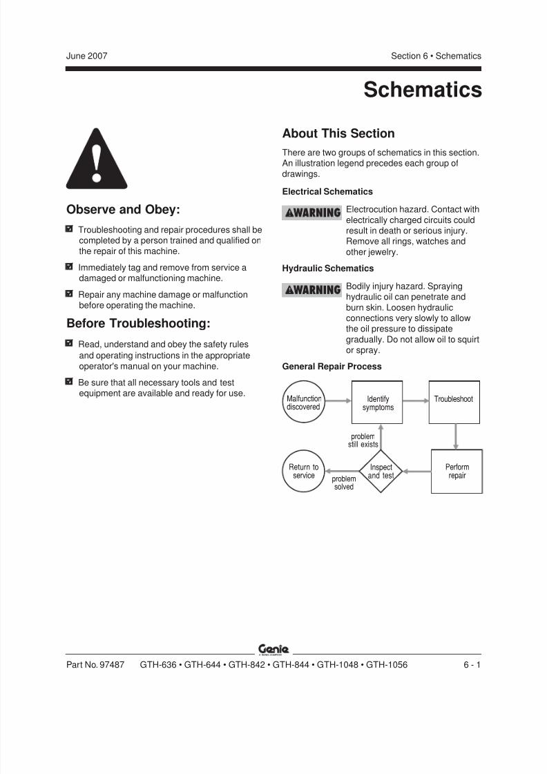
8/14/2019 Genie Manual de Servicio Gth-844
http://slidepdf.com/reader/full/genie-manual-de-servicio-gth-844 171/196
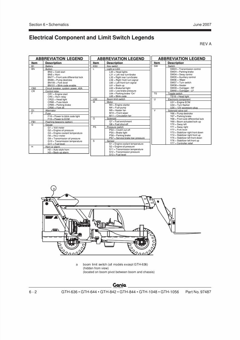
8/14/2019 Genie Manual de Servicio Gth-844
http://slidepdf.com/reader/full/genie-manual-de-servicio-gth-844 172/196
REV A
Section 6 • Schematics June 2007
6 - 2 GTH-636 • GTH-644 • GTH-842 • GTH-844 • GTH-1048 • GTH-1056 Part No. 97487
Electrical Component and Limit Switch Legends
a boom limit switch (all models except GTH-636)(hidden from view)(located on boom pivot between boom and chassis)
a
ABBREVIATION LEGENDItem DescriptionB1 Battery
ButtonBN
BN3 = Cold startBN5 = HornBN77 = Front axle differential lockBN99 = Pump destrokeBN100 = Fork levelBN101 = Blink code enable
CB2 Circuit breaker, system power, 40A
Control relayCR
CR1 = Engine startCR5 = Horn relayCR22 = Head lightCR88 = Fuse blockCR89 = Parking brakeCR90 = Fork tilt
D1 Alternator
FuseF
F18 = Power to blink code light
F19 = Power to ECMFB1 Flashing beacons (option)
GaugeG
G1 = Volt meterG2 = Engine oil pressureG3 = Engine coolant temperatureG6 = Hour meterG9 = Transmission oil pressureG10 = Transmission temperatureG11 = Fuel level
Horn or alarmH
H2 = Auto-style hornH3 = Back-up alarm
ABBREVIATION LEGENDItem Description
SwitchSW
SW23 = Transmission controlSW24 = Parking brakeSW34 = Sway controlSW35 = Auxiliary controlSW36 = WiperSW37 = Turn switchSW38 = HeaterSW39 = Outrigger - RFSW40 = Outrigger - LF
Toggle switchTS
TS18 = Head light
Electronic componentU
U31 = Engine ECMU34 = Turn flasherU35 = 12V accessory plug
Solenoid valve coilY
Y66 = Pump destrokeY67 = Parking brake
Y68 = Front axle differential lockY69 = Boom actuated lock-upY70 = Sway leftY71 = Sway rightY72 = Fork levelY73 = Stabilizer right front downY74 = Stabilizer right front upY75 = Stabilizer left front downY76 = Stabilizer left front upY77 = Controller relief
ABBREVIATION LEGENDItem DescriptionKS3 Key switch
Light or LEDL
L30 = Head lightsL31 = Left rear turn/brakeL32 = Right rear turn/brake
L59 = Right front turn signalL60 = Left front turn signalL61 = Back-upL62 = Brake/tail lightL63 = Low brake pressureL64 = Parking brake “On”L65 = Blink code
LS2 Boom limit switch
MotorM
M3 = Engine starterM4 = Fuel pumpM9 = Heater fanM10 = Front wiperM11 = Circulation fan
SolenoidQQ7 = Fuel enrichmentQ8 = Fuel shut-off
Pressure switchPS
PS4 = Clutch cut-offPS5 = Brake lightPS6 = Parking brakePS7 = Service brake low pressure
SensorS
S1 = Engine coolant temperatureS2 = Engine oil pressureS11 = Transmission temperatureS12 = Transmission pressureS13 = Fuel level
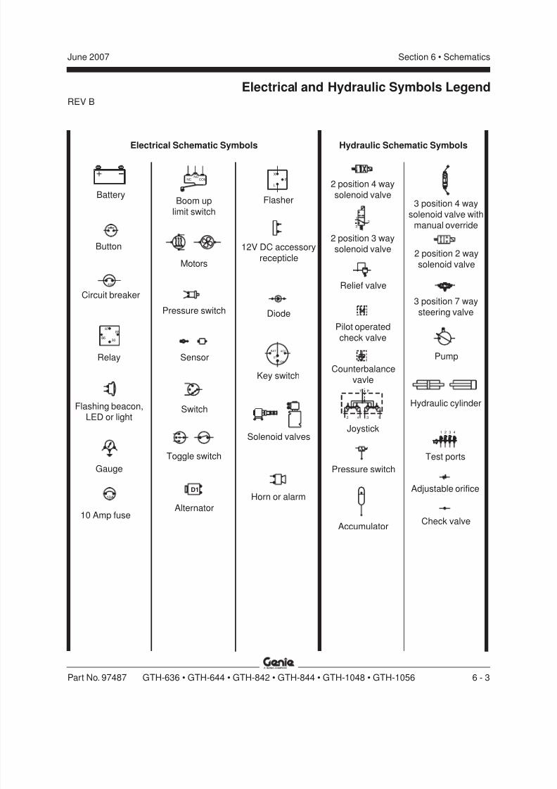
8/14/2019 Genie Manual de Servicio Gth-844
http://slidepdf.com/reader/full/genie-manual-de-servicio-gth-844 173/196
REV B
Section 6 • SchematicsJune 2007
Part No. 97487 GTH-636 • GTH-644 • GTH-842 • GTH-844 • GTH-1048 • GTH-1056 6 - 3
+ -
40A
87
3086
85
COMNO
NC
D1
X
L
P
IGN
BAT ACC
ST
42 3 1
PT
21
3
1 2 3 4
10A
Electrical and Hydraulic Symbols Legend
Electrical Schematic Symbols
Button
Circuit breaker
Relay
Flashing beacon,
LED or light
Gauge
Boom up
limit switch
Motors
Pressure switch
Sensor
Switch
Toggle switch
Alternator
Flasher
12V DC accessory
recepticle
Diode
Battery
Key switch
Solenoid valves
Horn or alarm
Hydraulic Schematic Symbols
2 position 4 way
solenoid valve
2 position 3 waysolenoid valve
Relief valve
Pilot operated
check valve
Counterbalance
vavle
Joystick
10 Amp fuse
Pressure switch
Accumulator
3 position 4 way
solenoid valve withmanual override
2 position 2 way
solenoid valve
3 position 7 way
steering valve
Pump
Hydraulic cylinder
Test ports
Adjustable orifice
Check valve

8/14/2019 Genie Manual de Servicio Gth-844
http://slidepdf.com/reader/full/genie-manual-de-servicio-gth-844 174/196
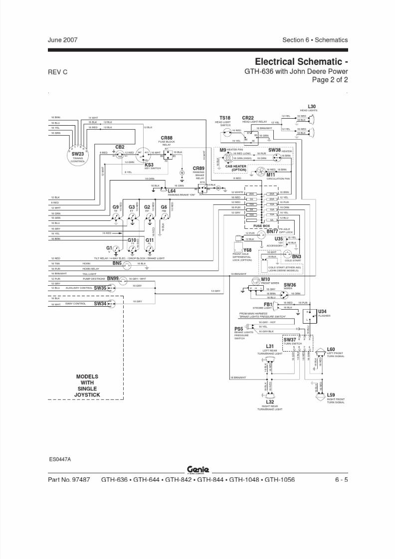
8/14/2019 Genie Manual de Servicio Gth-844
http://slidepdf.com/reader/full/genie-manual-de-servicio-gth-844 175/196
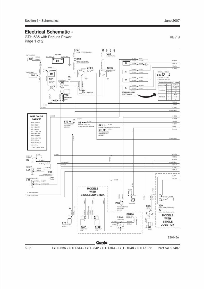
8/14/2019 Genie Manual de Servicio Gth-844
http://slidepdf.com/reader/full/genie-manual-de-servicio-gth-844 176/196

8/14/2019 Genie Manual de Servicio Gth-844
http://slidepdf.com/reader/full/genie-manual-de-servicio-gth-844 177/196
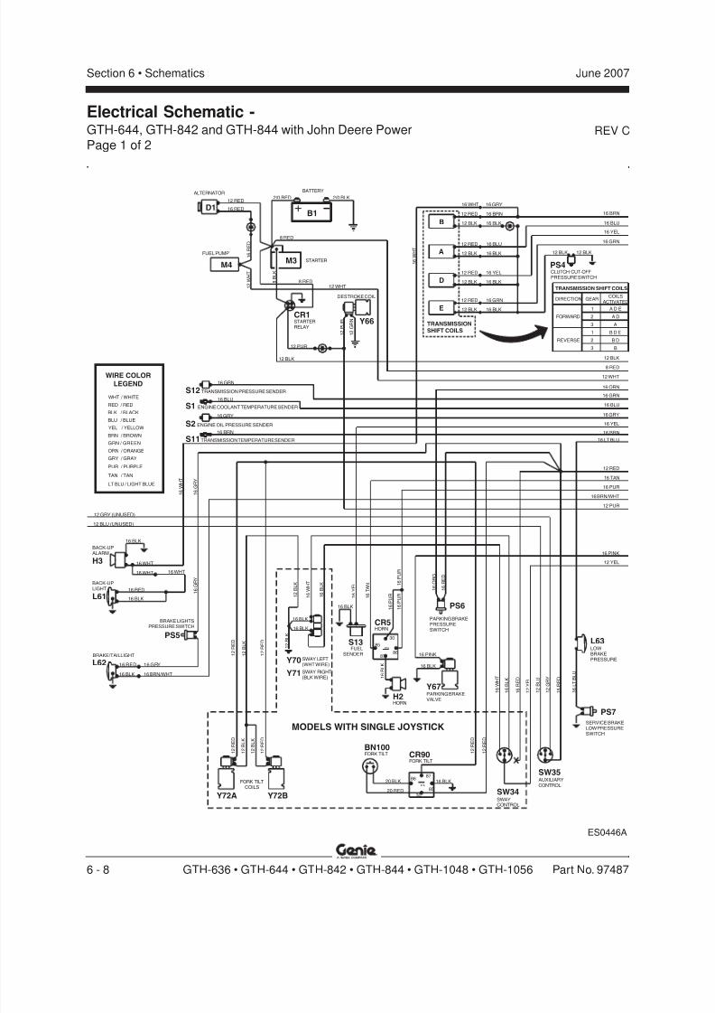
8/14/2019 Genie Manual de Servicio Gth-844
http://slidepdf.com/reader/full/genie-manual-de-servicio-gth-844 178/196
REV C
Section 6 • Schematics June 2007
6 - 8 GTH-636 • GTH-644 • GTH-842 • GTH-844 • GTH-1048 • GTH-1056 Part No. 97487
Electrical Schematic -GTH-644, GTH-842 and GTH-844 with John Deere PowerPage 1 of 2
ES0446A
16 WHT
BRAKE LIGHTSPRESSURE SWITCH
16 BLK
BRAKE/TAIL LIGHT
16 BRN/WHT
16 RED 16 GRY
16 BLK
BACK-UPLIGHT 16 RED
12 BLU (UNUSED)
BACK-UPALARM
16 BLK
16 WHT
16 WHT
12 GRY (UNUSED)
1 6 G R Y
1 2 R E D
1 2 B L K
1 2 R E D
SERVICE BRAKELOW PRESSURESWITCH
SWAYCONTROL
AUXILIARYCONTROL
1 2 B L U
1 6 W H T
1 6 B L K
1 6 R E D
1 2 Y E L
1 6 L T B L U
1 2 G R Y
1 6 R E D
1 6 G R Y
1 6 W H T
12 RED
16 TAN
16 BRN/WHT
12 PUR
16 PUR
16 GRY
16 YEL
16 BRN
16 LT BLU
12 BLK
16 BLU
16 GRN
16 ORN
12 WHT
8 RED
16 WHT
12 RED
12 BLK
12 RED
12 BLK
12 RED
12 BLK
12 BLK
12 RED
2/0 RED
12 BLK
12 PUR
1 6 R E D
FUEL PUMP
8 RED
STARTER
8 B L K
E
TRANSMISSIONSHIFT COILS
12 WHT
8 RED
1 6 W H T
A
D
ALTERNATOR
16 RED
12 RED
BATTERY
+2/0 BLK
-
B
16 YEL
CLUTCH CUT-OFFPRESSURE SWITCH
16 BLK
16 GRN
16 BLK
16 BLK
16 BLU
16 YEL
16 GRN
16 GRY
16 BRN
16 BLK
16 BRN
16 BLU
16 PINK
12 YEL
1 2
W H T
/ BLUE
LT BLU / LIGHT BLUE
YEL
BRN
/ YELLOW
/ BROWN
ORN
GRY
TAN
PUR
/ ORANGE
/ GRAY
/ TAN
/ PURPLE
GRN / GREEN
BLU
WHT
RED
BLK
/ WHITE
/ RED
/ BLACK
WIRE COLOR
LEGEND
PS7
PS5
12 BLK
PS4
12 BLK
COILSACTIVATED
GEAR
1 A D E
2 A D
3 A
B D E1
B D2
B3
TRANSMISSION SHIFT COILS
DIRECTION
FORWARD
REVERSE
D1
M4
B1
M3
SW34
SW35FORK TILT
COILS
1 2 B L K
1 2 R E D
1 2 B L K
1 2 R E D
Y72A Y72B
H3
L61
L62
LOWBRAKEPRESSURE
L63
STARTERRELAY
CR1
1 2 P U R
1 2 G R N
DESTROKE COIL
Y66
16 GRY
S1 ENGINE COOLANT TEMPERATURE SENDER
16 BLU
S2 ENGINE OIL PRESSURE SENDER
16 GRN
S12 TRANSMISSION PRESSURE SENDER
16 BRN
S11 TRANSMISSION TEMPERATURE SENDER
PARKING BRAKEVALVE
1 2
B L K
1 6 B L K
87A
16 BLK
16 PINK
1 6
B L K
1 6
W H T
1 2 B L K
16 BLK
16 BLK
1 6 O R G
1 6 T A N
1 6 Y E L
1 6 R E D
1 6 P U R
16 BLK 1 6 P U R
PARKING BRAKEPRESSURESWITCH
1 6 P U R
8786
30
85
PS6
Y67
CR5HORN
H2HORN
S13FUEL
SENDER
20 RED
87A
20 BLK 16 BLK
1 2 R E D
1 2 R E D
8786
30
85
CR90FORK TILT
BN100FORK TILT
Y70 SWAY LEFT(WHT WIRE)
Y71 SWAY RIGHT(BLK WIRE)
MODELS WITH SINGLE JOYSTICK
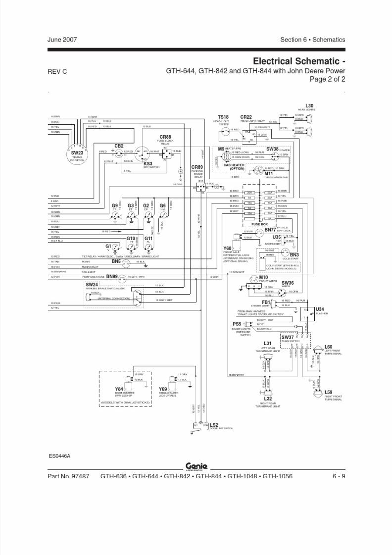
8/14/2019 Genie Manual de Servicio Gth-844
http://slidepdf.com/reader/full/genie-manual-de-servicio-gth-844 179/196
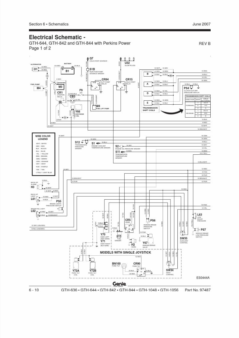
8/14/2019 Genie Manual de Servicio Gth-844
http://slidepdf.com/reader/full/genie-manual-de-servicio-gth-844 180/196
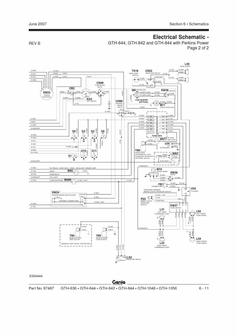
8/14/2019 Genie Manual de Servicio Gth-844
http://slidepdf.com/reader/full/genie-manual-de-servicio-gth-844 181/196
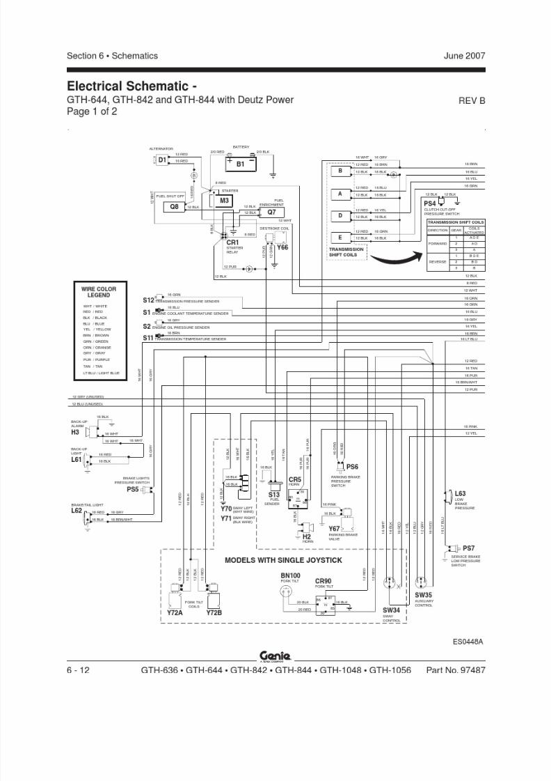
8/14/2019 Genie Manual de Servicio Gth-844
http://slidepdf.com/reader/full/genie-manual-de-servicio-gth-844 182/196
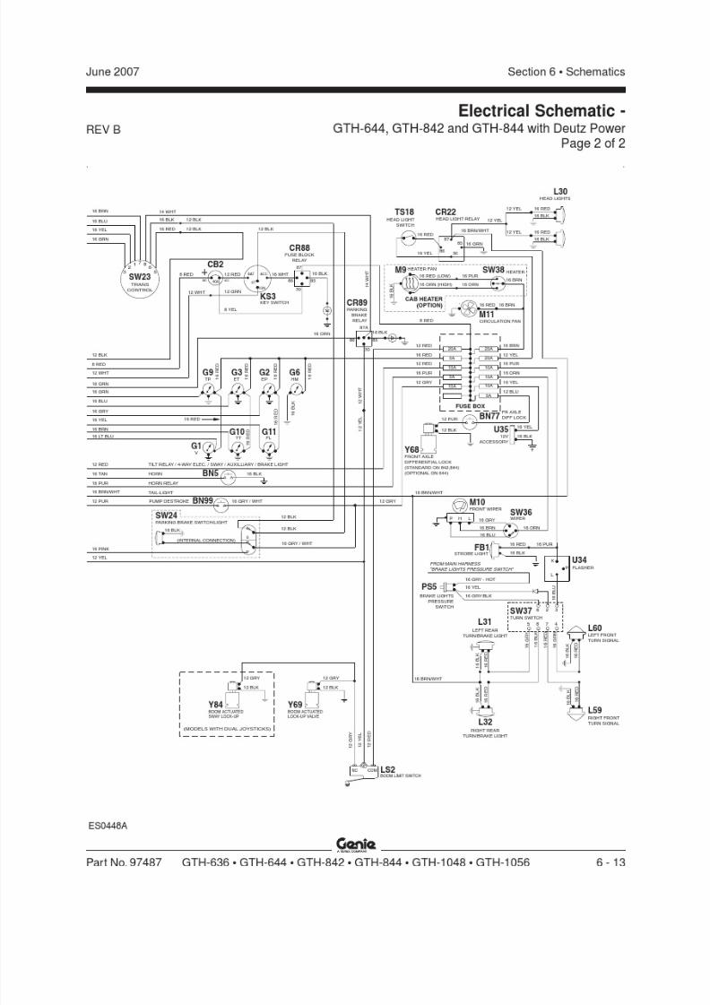
8/14/2019 Genie Manual de Servicio Gth-844
http://slidepdf.com/reader/full/genie-manual-de-servicio-gth-844 183/196

8/14/2019 Genie Manual de Servicio Gth-844
http://slidepdf.com/reader/full/genie-manual-de-servicio-gth-844 184/196
REV C
Section 6 • Schematics June 2007
6 - 14 GTH-636 • GTH-644 • GTH-842 • GTH-844 • GTH-1048 • GTH-1056 Part No. 97487
Electrical Schematic -GTH-1048 and GTH-1056 with John Deere PowerPage 1 of 2
BATTERY
UNSWITCHED ECU POWER
16 GRY
8 RED
1 2
P U R STARTER
RELAY
1 2 R E D
12 RED
16 RED
ALTERNATOR
+
8 B L K
STARTER
8 RED
2/0 RED
FORK TILTCOILS
1 2
R E D
1 2
B L K
1 2
R E D
1 2
B L K
1 6
P N K
1 2
B L K
12 BLK
1 6
B L K
8785
87A
30
86
ENGINE ECU HARNESS
16 TAN
1 6
P U R
1 6
P U R
1 6
P U R
1 6
T A N
16 PUR
12 GRY
12 PUR
16 BRN/WHT
12 BLU
J 16 RED/WHT
16 GRN
16 BLU
16 YEL
16 GRY
8 RED
16 ORN
12 RED
16 BRN
1 6
P U R
10A
D12 RED
ENGINEECM
J16 RED
-
2/0 BLK
1 0
R E D
16 BRN
1 6
W H T
1 0
B L K
SWITCHED & FUSED ECU POWER
N
H
G
R
S
C
L
M
P
D
16 GRY/WHT
12 RED/BLK
16 ORN/WHT
16 WHT
16 BRN/WHT
16 YEL/WHT
16 GRN/WHT
16 BLU/WHT
390 OHM
RESISTOR
12 RED/WHT
390 OHMRESISTOR
16 GRN/WHT
16 BLU/WHTCOILSACTIVATED
GEAR
1 F 2 1
2 F 2
3 F
R 2 11
R 22R3
TRANSMISSIONSHIFT COILS
DIRECTION
FORWARD
REVERSE
D1B1
M3
CR1
CONTROLLER
RELIEF VALVE
Y77
Y72A Y72B
CR5HORN
H2HORN
FUELSENDER
S13
PARKING BRAKE
PRESSURESWITCH
PS6
F19 10 AMP
FUSE
U31
12 RED/BLK
12 RED/WHT
16 RED/WHT
16 ORN/WHT
16 GRY/WHT
16 BRN/WHT
S11 TRANSMISSION TEMPERATURE SENDER
S2 ENGINE OIL PRESSURE SENDER
S1 ENGINE COOLANT TEMPERATURE SENDER
16 BLU
16 GRN
S12 TRANSMISSION PRESSURE SENDER
/ BLUE
LT BLU / LIGHT BLUE
YEL
BRN
/ YELLOW
/ BROWN
ORN
GRY
TAN
PUR
/ ORANGE
/ GRAY
/ TAN
/ PURPLE
GRN / GREEN
BLU
WHT
RED
BLK
/ WHITE
/ RED
/ BLACK
WIRE COLOR
LEGEND
1 2 P U R
1 2 G R N
DESTROKE COIL
Y66
ES0450A
BACK-UP
LIGHT
BRAKE/TAILLIGHT
16 RED
16 BLK
16 GRY
16 BRN/WHT
16 RED
16 BLK
16 BLK
12 GRY
12 BLU
BACK-UPALARM
1 6 G R Y
16 WHT
16 WHT
16 WHT
16 WHT
H3
L61
L62
BRAKE LIGHTS
PRESSURE SWITCH
PS5
1 6
Y E L16 BLK
1 6 B L K
1 6 B L U
1 6 B L K
1 6 B L K
1 6 Y E L
1 6 G R N
1 6 B L K
1 6 B R N
TRANS
CONTROL
TRANSMISSION SHIFT COILS
REVFWD 1 ST2 ND
16 YEL
16 GRN
16 BLU
16 BRN
14 WHT
16 BLK
16 RED
SW23
12 BLK12 BLK
CLUTCH
CUT-OFF
PRESSURESWITCH
PS42
17
3 86
5
16 GRY
30
8687A
16 BLK
8587
CR90FORK TILT
BN100FORK TILTBUTTON
12 RED
12 RED
1 6
R E D
1 6
O R G
1 2
R E D
MODELS WITH SINGLE JOYSTICK
20 RED
20 BLK
16 BLK16 BLK
16 BLK
16 WHT
16 BLK
Y70 SWAYLEFT(WHTWIRE)
Y71 SWAYRIGHT(BLK WIRE)
MODELS
WITH
SINGLEJOYSTICK
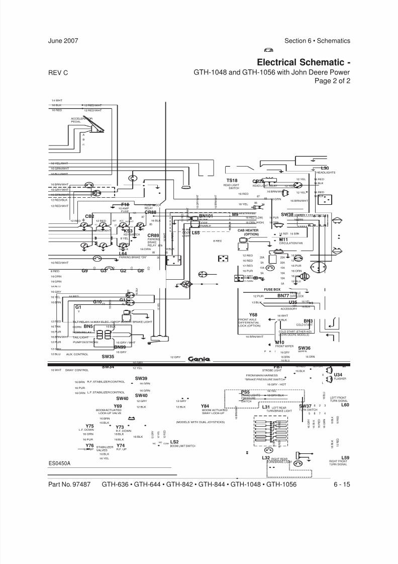
8/14/2019 Genie Manual de Servicio Gth-844
http://slidepdf.com/reader/full/genie-manual-de-servicio-gth-844 185/196
REV C
Section 6 • SchematicsJune 2007
Part No. 97487 GTH-636 • GTH-644 • GTH-842 • GTH-844 • GTH-1048 • GTH-1056 6 - 15
Electrical Schematic -GTH-1048 and GTH-1056 with John Deere Power
Page 2 of 2
16 BRN/WHT
12 BLU
12 YEL
16 PUR
16 BRN
16 ORN
16 YEL
16 RED
HORN RELAY
PUMP DESTROKE
TILT RELAY / 4-WAY ELEC. / DROP BLOCK / BRAKE LIGHT
AUX. CONTROL
HORN
TAIL-LIGHT
16 GRY/BLK
16 BLK
16 BLK
16 BLK
16 BLK
16 BLK
16 BRN
16 ORN
16 PUR
16 YEL
NC NO
1 2
G R Y
1 2
R E D
1 2
Y E L
COM
12 BLK
12 GRY
1 6
B R N / W H T
1 6
B L K
1 6
R E D
1 6
B L K
1 6
R E D
16 BLK
16 GRY / WHT
16 GRY
12 YEL
16 PUR
16 ORN
16 BRN
16 GRY
12 GRY
16 GRN
1 6
R E D
1 6
R E D
1 6
R E D
1 6
R E D
1 2
W H T
1 6
R E D
1 6
B L K
1 2
Y E L
16 YEL
FROM MAIN HARNESS
"BRAKE PRESSURE SWITCH"
16 GRY - HOT
12 GRN
12 RED
12 GRY
16 PUR
12 PUR
16 WHT
16 BLKFRONT AXLE
DIFFERENTIAL
LOCK (OPTION)
12 BLK
B
C
A
8 RED
1 6
O R N / W H T
12 RED/BLK
12 RED/WHT
16 BLK
16 ORN
12 RED 16 WHT
8 YEL
12 RED/BLK
1 4
W H T
16 BLK16 ORN
1 6
R E D
16 BLK
ACCELERATORPEDAL
16 BRN/WHT
12 RED
1 6
B R N / W H
T
1 6
G R Y / W H
T
16 GRN
16 RED
16 YEL
12 YEL
12 RED/WHT
12 RED/WHT
1 6 B L U
1 6 R E D
1 6
R E D
1 6
B L K
1 6 B L K
16 BRN/WHT
16 RED
16 BLK
16 PUR
12 YEL 16 RED
16 BLK
HEADLIGHTS
12 YEL
16 BLK
16 RED
TP ET EP HM
FLTT
V
ACC.40ABAT.
+
10A
IGN
BAT ACC
ST
87
86
30
85
87A
30
86 85
87
3086
85
1 6 B L K 16 ORN (HIGH)
CIRCULATION FAN
16 RED 16 BRN
16 RED (LOW)16 BRN
SW38 HEATER
CAB HEATER
(OPTION)
M11
M9 HEATER FAN
16 ORN
16 PUR
20A
FUSE BOX
5A
5A
10A
10A
20A
20A
10A
10A
10A
5A
16 GRY
16 BRN
16 BLU
16 ORN
LHP
FRONT WIPERM10
SW36WIPER
FLASHER
X
L
P
U34
1 6 R E D
1 6 G R N
1 6 G R Y
1 6 B L K
3
4
2
75
6
8
TURN SWITCHSW37
16 BLK
16 YEL
RIGHT FRONTTURN SIGNAL
LEFT FRONTTURN SIGNAL
LEFT REARTURN/BRAKE LIGHT
RIGHT REARTURN/BRAKE LIGHT
14 WHT
16 BLK
16 RED
8 R E D
16 GRN
16 BRN
16 YEL
16 BLU
16 GRY
16 ORN
8 RED
16 RED
1 6 R E D
BOOM LIMIT SWITCH
TS18HEAD LIGHT
SWITCH
CR22HEAD LIGHT RELAY
L30
CR89PARKINGBRAKERELAY
KS3KEY SWITCH
Y68
COLD START (ETHER AID)(JOHN DEERE MODELS)
BN3COLD START
12VACCESSORY
U35
STROBE LIGHTFB1
PS5BRAKE LIGHTSPRESSURESWITCH
L31
L32
L60
L59
BN77
FR AXLE
DIFF LOCK
LS2
Y69
CR88
FUSE BLOCKRELAY
G9 G3 G2 G6
G1G10 G11
BN99
BN5
SW35
SW39
SW40
R.F. STABILIZER CONTROL
L.F. STABILIZER CONTROL
Y76L.F. UP
Y75L.F. DOWN
Y73R.F. DOWN
Y74R.F. UP
STABILIZER
VALVES
L65
L64
BLINK
CODE
LIGHT
PARKING BRAKE “ON”
BN101BLINK
CODE
ENABLE
CB2
F1810 AMP
FUSE
16 RED/WHT
16 RED/WHT
12 RED
16 ORN/WHT
16 GRY/WHT
16 BRN/WHT
16 BLU/WHT
16 GRN/WHT
16 YEL/WHT
12 BLU
12 GRY
12 PUR
16 BRN/WHT
16 PUR
16 TAN
12 RED
ES0450A
BOOM ACTUATED
SWAY LOCK-UP
12 BLK
12 GRY
Y84
(MODELS WITH DUAL JOYSTICKS)
BOOM ACTUATED
LOCK-UP VALVE
SW40
16 GRN
SWAY CONTROLSW34
16 WHT
16 BLK

8/14/2019 Genie Manual de Servicio Gth-844
http://slidepdf.com/reader/full/genie-manual-de-servicio-gth-844 186/196
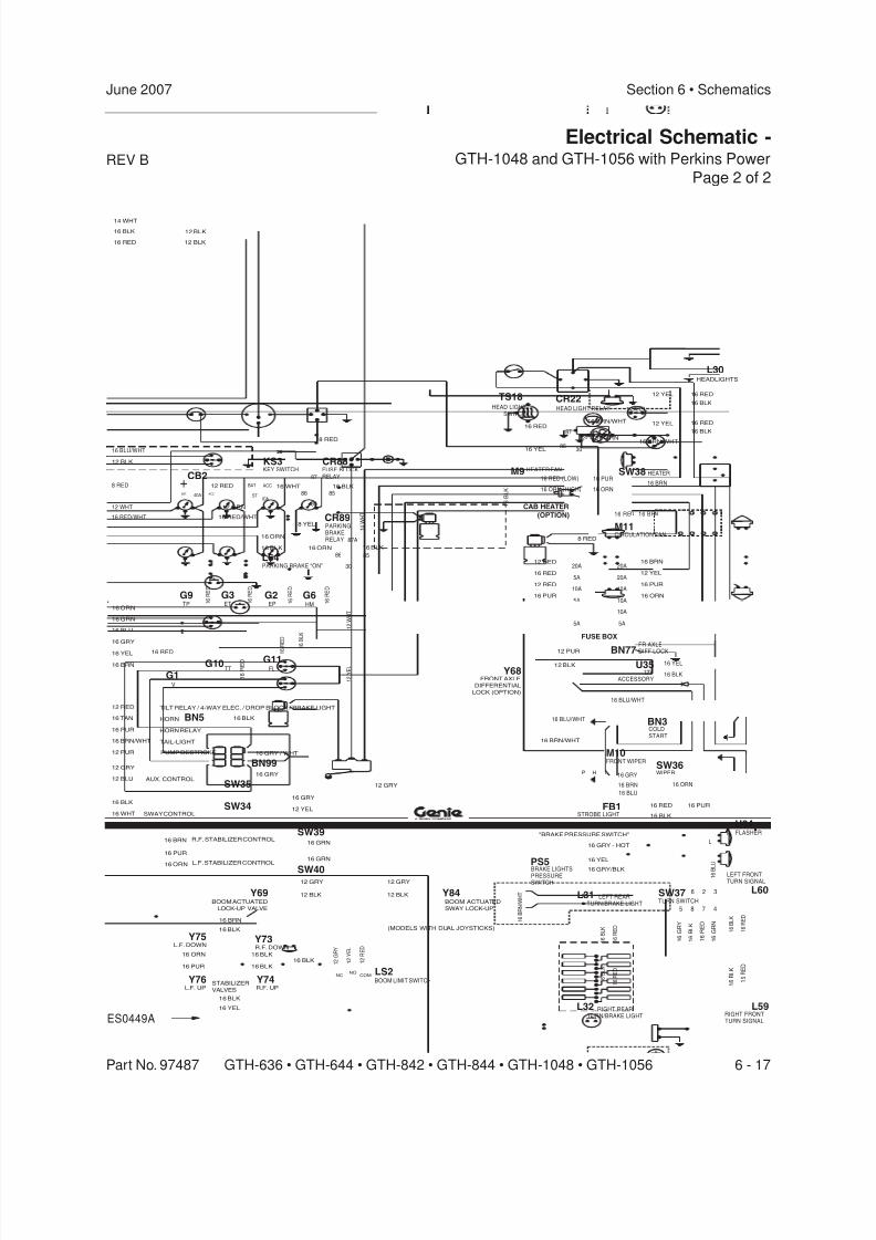
8/14/2019 Genie Manual de Servicio Gth-844
http://slidepdf.com/reader/full/genie-manual-de-servicio-gth-844 187/196
REV B
Section 6 • SchematicsJune 2007
Part No. 97487 GTH-636 • GTH-644 • GTH-842 • GTH-844 • GTH-1048 • GTH-1056 6 - 17
Electrical Schematic -GTH-1048 and GTH-1056 with Perkins Power
Page 2 of 2
16 BRN/WHT
12 BLU
12 YEL
16 PUR
16 BRN
16 ORN
16 YEL
16 RED
HORN RELAY
PUMP DESTROKE
TILT RELAY / 4-WAY ELEC. / DROP BLOCK / BRAKE LIGHT
AUX. CONTROL
HORN
TAIL-LIGHT
16 GRY/BLK
16 BLK
16 BLK
16 BLK
16 BLK
16 BLK
16 BRN
BOOM ACTUATED
LOCK-UP VALVE
16 ORN
16 PUR
16 YEL
NC NO
1 2
G R Y
1 2
R E D
1 2
Y E L
COM
12 BLK
12 GRY
1 6
B R N / W H T
1 6
B L K
1 6
R E D
1 6
B L K
1 6
R E D
16 BLK
16 GRY / WHT
16 PUR
16 ORN
16 BRN
16 GRY
12 GRY
16 GRN
1 6
R E D
1 6
R E D
1 6
R E D
1 6
R E D
1 2
W H T
1 6
R E D
1 6
B L K
1 2
Y E L
16 YEL
FROM MAIN HARNESS
"BRAKE PRESSURE SWITCH"
16 GRY - HOT
12 GRN
12 RED
12 GRY
16 PUR
12 PUR
12 BLK
12 BLK
16 BLK
16 ORN
12 RED 16 WHT
8 YEL 1 4
W H T
16 BLK16 ORN
16 BLK
16 BRN/WHT
12 RED
16 GRN
16 RED
16 YEL
12 YEL
1 6 B L U
1 6 R E D
1 6
R E D
1 6
B L K
1 6 B L K
16 BRN/WHT
16 RED
16 BLK
16 PUR
12 YEL 16 RED
16 BLK
HEADLIGHTS
12 YEL
16 BLK
16 RED
TP ET EP HM
FLTT
V
ACC.40ABAT.
+IGN
BAT ACC
ST
87
86
30
85
87A
30
86 85
87
3086
85
1 6 B L K 16 ORN (HIGH)
CIRCULATION FAN
16 RED 16 BRN
16 RED (LOW)16 BRN
SW38 HEATER
CAB HEATER
(OPTION)
M11
M9 HEATER FAN
16 ORN
16 PUR
20A
FUSE BOX
5A
5A
10A
10A
20A
20A
10A
10A
10A
5A
16 GRY
16 BRN
16 BLU
16 ORN
LHP
FRONT WIPERM10
SW36WIPER
FLASHER
X
L
P
U34
1 6 R E D
1 6 G R N
1 6 G R Y
1 6 B L K
3
4
2
75
6
8
TURN SWITCHSW37
16 BLK
16 YEL
RIGHT FRONTTURN SIGNAL
LEFT FRONTTURN SIGNAL
LEFT REARTURN/BRAKE LIGHT
RIGHT REARTURN/BRAKE LIGHT
16 GRN
16 BRN
16 YEL
16 BLU
16 GRY
16 ORN
16 RED
1 6 R E D
BOOM LIMIT SWITCH
TS18HEAD LIGHT
SWITCH
CR22HEAD LIGHT RELAY
L30
CR89PARKINGBRAKERELAY
KS3KEY SWITCH
12VACCESSORY
U35
STROBE LIGHTFB1
PS5BRAKE LIGHTSPRESSURESWITCH
L31
L32
L60
L59
BN77
FR AXLE
DIFF LOCK
LS2
Y69
G9 G3 G2 G6
G1G10 G11
BN99
BN5
SW35
ES0449A
R.F. STABILIZER CONTROL
L.F. STABILIZER CONTROL
Y76L.F. UP
Y75L.F. DOWN
Y73R.F. DOWN
Y74R.F. UP
STABILIZER
VALVES
L64PARKING BRAKE “ON”
CB2
16 RED/WHT
12 BLU
12 GRY
12 PUR
16 BRN/WHT
16 PUR
16 TAN
12 RED
5A
12 GRN
8 RED
8 RED
FRONT AXLE
DIFFERENTIAL
LOCK (OPTION)
Y68
CR88FUSE BLOCKRELAY
BN3COLDSTART
8 RED
12 WHT
16 RED/WHT
16 BLU/WHT
16 BLU/WHT
16 BLU/WHT
12 BLK
14 WHT
16 BLK
16 RED 12 BLK
BOOM ACTUATED
SWAY LOCK-UP
12 BLK
12 GRY
Y84
(MODELS WITH DUAL JOYSTICKS)
SWAY CONTROLSW34
16 WHT
16 BLK16 GRY
12 YEL
16 GRN
SW39
SW40
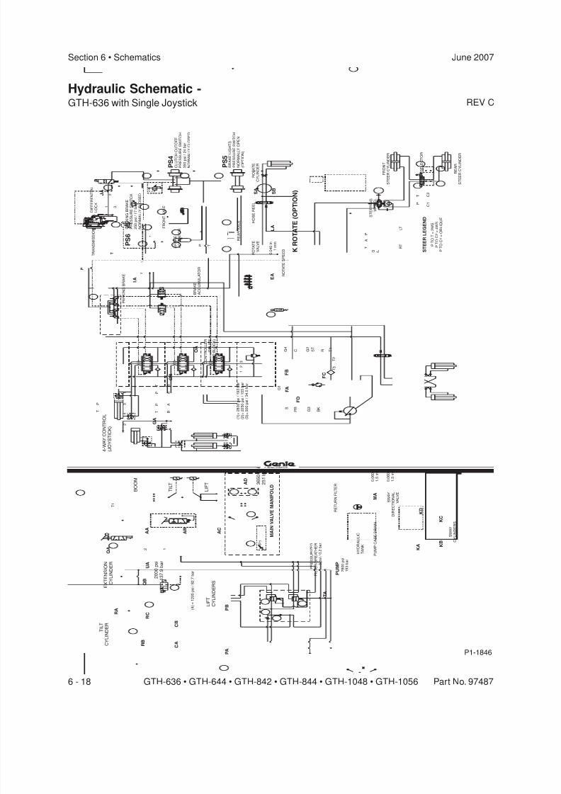
8/14/2019 Genie Manual de Servicio Gth-844
http://slidepdf.com/reader/full/genie-manual-de-servicio-gth-844 188/196
REV C
Section 6 • Schematics June 2007
6 - 18 GTH-636 • GTH-644 • GTH-842 • GTH-844 • GTH-1048 • GTH-1056 Part No. 97487
Hydraulic Schematic -GTH-636 with Single Joystick
P1-1846
T I L T
C Y L I N D E R
E X T E N
S I O N
C Y L I N D E R
L I F T
C Y L I N D E R
S
1
2
3
( 1
) = 2
8 0 0
p s
i / 1
9 3
b a r
( 2
) = 2
2 5 0
p s
i / 1
5 5
b a r
( 3
) = 5
0 0
p s
i / 3
4 . 5 b
a r
M A I N
V A L V E M A N I F O L D
P 1
T 1
B O O M
T I L T
L I F T 3
6 5 0
p s
i
2 5 1
b a r
4
2
3
1
P
T
P
T
P
T
A
B
A
B
G A
G B
Q A
A A
A B
A C
A D
Q B
R A
R C
R B
C B
C A
P B
M A
0 . 0
6 0
i n
1 . 5 m
m
0 . 0
6 0
i n
1 . 5 m
m
S W A Y
D I R E C T I O N A L
V A L V E
R E T U R N F I L T E R
P R E S S U
R I Z E D
F I L T E R / B R E
A T H E R
3 p
s i / 0
. 2 b
a r
H Y D R A U L I C
T A N K
P U M P
C A S E D R A I N
4 - W
A Y
C O N T R O L
( J O Y
S T I C K
)
S W A Y
C Y L I N D E R S
K A K
B
K C
K D
S T E E R I N G
O R B I T R A L
S T E E R I N G
W H E E L
F R O N T
S T E E R C Y L I N D E R
R E A R
S T E E R C Y L I N D E R
S T E E R S E L E C T O R
P
T
C 1
C 2
P T
O T
= 2
W S
P T
O C 2
= 4
W S
P T
O C 1
= O
B L I Q U E
S T E E R
L E G E N D
R T
L T
P
A
T
0 . 0
4 0
i n
1 m
m
R O T A T E
V A L V E
S B
S A
L A
R O T A T E
C Y L I N D E R
H O S E R E E L
F O R K
R O T A T E
( O P T I O N )
R E A R A X L E
B R A K E L I G H T S
P R E S S U R E S W I T
C H
N O R M A L L Y
O P E N
( O P T I O N )
C L U T C H C U T O F F
P R E S S U R E S W I T
C H
3 5 0
p s
i / 2
4 b
a r
N O R M A L L Y
C L O S
E D
B R A K E
A C T U A T O R
B R A K E
A C C U M U L
A T O R
F R O N T
A X L E
P A R K I N G B R A K E
P R E S S U R E S W I T C H
2 5 0
p s
i / 1
7 b
a r
N O R M A L L Y
C L O S E D
P A R K I N G B R A K
E
T
P
T R A N S M I S S I O N
D I F F E R E N T I A L
L O C K
J A
I A
2
1 3
E
A R O T A T E S P E E D
P S 4
P S 6
P S 5
T P
A
3 2
1
S P R
B K
G 3
G 4
C R S T
G 2
T 1
T 2
T 3
G 1
4
P A
( 4 )
= 1 2 0 0 p s
i / 8
2 . 7
b a r
F B
F D
F C
F A
C O N T R O L L E R
R E L I E F
( D R O P B L O C K )
O A
B A
1 2
U A
N O T E :
I T E M ‘ U A ’
W A S R E M O V E D F R O M
T H
E M A C H I N E A F T E R S E R I A L N U M B E R
G T H 0 6 0 6 A - 9
0 2 2
2 0 0 0
p s
i
1 3 7
. 9 b
a r
T A
P U M P
2 8 0 0
p s i
1 9 3
b a r
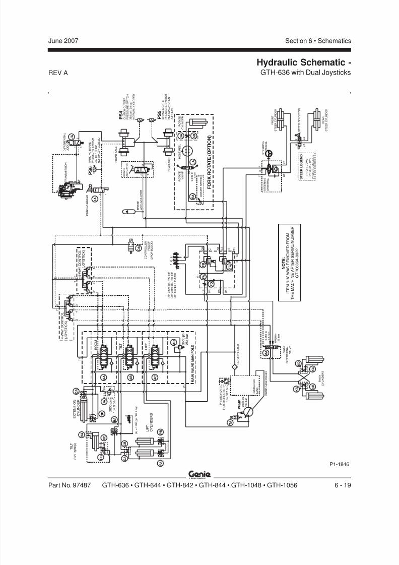
8/14/2019 Genie Manual de Servicio Gth-844
http://slidepdf.com/reader/full/genie-manual-de-servicio-gth-844 189/196
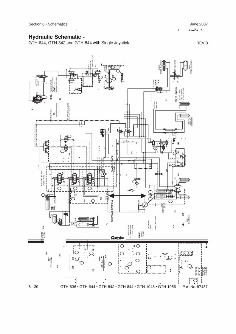
8/14/2019 Genie Manual de Servicio Gth-844
http://slidepdf.com/reader/full/genie-manual-de-servicio-gth-844 190/196
REV B
Section 6 • Schematics June 2007
6 - 20 GTH-636 • GTH-644 • GTH-842 • GTH-844 • GTH-1048 • GTH-1056 Part No. 97487
Hydraulic Schematic -GTH-644, GTH-842 and GTH-844 with Single Joystick
P1-1971P1-1962P1-1940
T I L T
C Y L I N D E R
E X T E N
S I O N
C Y L I N D E R
L I F T
C Y L I N D E R
S
1
2
3 4 G
4
G 2
C S T
R T 1
T 2
T 3
G 1
B K
G
3
P
R S
( 1 ) =
3 0 0 0
p s
i / 2
0 7
b a r
( 2 ) =
2 2 5 0
p s
i / 1
5 5
b a r
( 3 ) =
5 0 0
p s
i / 3
4 . 5 b
a r
( 4 ) =
1 2 5 0
p s
i / 8
6 . 2 b
a r
M A I N
V A L V E M A N I F O L D
P 1
T 1
B O O M
T I L T
L I F T 3
6 5 0
p s
i
2 5 1
b a r
4
2
3
1
P
T
P
T
P
T
A
B
A
B
G A
G B
Q A
A A
A B
A C
A D
Q B
R A
R C
R B
C B
C A
P B
P A
M A
0 . 0
6 0
i n
1 . 5 m
m
0 . 0
6 0
i n
1 . 5 m
m
S W A Y
D I R E C T I O N A L
V A L V E
R E T U R N F I L T E R
P R
E S S U R I Z E D
F I L T E R
/ B R E A T H E R
3 p
s i
/ 0
. 2 b
a r
H Y D R A U L I C
T A N K
P U M P
C A S E D R A I N
P U M
P
3 0 0 0
p s
i
2 0 7
b a r
4 - W
A Y
C O N T R
O L
( J O Y
S T I C K )
S W A Y
C Y L I N D E R S
K A K
B
K C
K D
B
P
C 1
C 2
D A
F C
F A
F D
F B
T S 1
S 2
C 3
C 4
T A N K
H F
H G
H C
H B
H A
H
E
R E A R
L O C K
- U P
C Y L I N D E R S
H D
H H
S T E E R I N G
O R B I T R A L
S T E E R I N G
W H E E L
F R O N T
S T E E R C Y L I N D E R
R E A R
S T E E R C Y L I N D E R
S T E E R S E L E C T O R
P
T
C 1
C 2
P T
O T
= 2
W S
P T
O C 2
= 4
W S
P T
O C 1
= O
B L I Q U E
S T E E R
L E G E N D
R T
L T
P
A
T
0 . 0
4 0
i n
1 m
m
R O T A T E
V A L V E
S B
S A
L A
R O T A T E
C Y L I N D E R
H O S E R E E L
F O R K
R O T A T E
( O P T I O N )
R E A R A X L E
B R A K E L I G H T S
P R E S S U R E S W I T C H
N O R M A L L Y
O P E N ( O P T I O N )
A
C L U T C H C U T O F F
P R E S S U R E S W I T C H
3 5 0
p s
i / 2
4 b
a r
N O R M A L L Y
C L O S E D
B R A K E
A C T U A T O R
L O W B
R A K E P R E S S U R E
P R E S S U R E S W I T C H
1 0 0 0 p
s i
/ 6
9 b
a r
N O R M
A L L Y
C L O S E D
B R A K E
A C C U M U L A T O
R
F R O N T
A X L E
P A R K I N G B R A K E
P R E S S U R E S W I T C H
2 5 0
p s
i / 1
7 b
a r
N O R M A L L Y
C L O S E D
P T
2
1 3
P A R K I N
G B R A K E
T
P
T R A N S M I S S I O N
D I F F E R E N T I A L
L O C K
J A
I A
2
1 3
E A
R O T A T E
S P E E D
C O N T R O L B L O C K
M A N I F O L D
R E A R
L O C K
- U P
M A N I F O L D
P S 4
P S 7
P S 6
P S 5
G T H
- 8 4 4
M O D E L
S C B
C A
N A
G T H
- 6 4 4
• G
T H
- 8 4 2
M O D E L
S
B A
T A

8/14/2019 Genie Manual de Servicio Gth-844
http://slidepdf.com/reader/full/genie-manual-de-servicio-gth-844 191/196
REV A
Section 6 • SchematicsJune 2007
Part No. 97487 GTH-636 • GTH-644 • GTH-842 • GTH-844 • GTH-1048 • GTH-1056 6 - 21
Hydraulic Schematic -GTH-644, GTH-842 and GTH-844 with Dual Joysticks
P1-1971P1-1962P1-1940
T I L T
C Y L I N D E R
E X T E N
S I O N
C Y L I N D E R
L I F T
C Y L I N D E R
S
1
2
3 4 G
4
G 2
C S T
R T 1
T 2
T 3
G 1
B K
G
3
P
R S
( 1 ) =
3 0 0 0
p s
i / 2
0 7
b a r
( 2 ) =
2 2 5 0
p s
i / 1
5 5
b a r
( 3 ) =
5 0 0
p s
i / 3
4 . 5 b
a r
( 4 ) =
1 2 5 0
p s
i / 8
6 . 2 b
a r
M A I N
V A L V E M A N I F O L D
P 1
T 1
B O O M
T I L T
L I F T 3
6 5 0
p s
i
2 5 1
b a r
Q A
A A
A B
A C
A D
Q B
R A
R C
R B
C B
C A
P B
P A
R E T U R N F I L T E R
P R
E S S U R I Z E D
F I L T E R
/ B R E A T H E R
3 p
s i
/ 0
. 2 b
a r
H Y D R A U L I C
T A N K
P U M P
C A S E D R A I N
4
2
3
1
P
T
4 - W
A Y
C O N T R
O L
( J O Y
S T I C K
)
S W A Y
C Y L I N D E R S
K A K
B
K C
K D
B
P
C 1
C 2
D A
F C
F A
F D
F B
T S 1
S 2
C 3
C 4
T A N K
H F
H G
H C
H B
H A
H
E
R E A R
L O C K
- U P
C Y L I N D E R S
H D
H H
S T E E R I N G
O R B I T R A L
S T E E R I N G
W H E E L
F R O N T
S T E E R C Y L I N D E R
R E A R
S T E E R C Y L I N D E R
S T E E R S E L E C T O R
P
T
C 1
C 2
P T
O T
= 2
W S
P T
O C 2
= 4
W S
P T
O C 1
= O
B L I Q U E
S T E E R
L E G E N D
R T
L T
P
A
T
0 . 0
4 0
i n
1 m
m
R O T A T E
V A L V E
S B
S A
L A
R O T A T E
C Y L I N D E R
H O S E R E E L
F O R K
R O T A T E
( O P T I O N )
R E A R A X L E
B R A K E L I G H T S
P R E S S U R E S W I T C H
N O R M A L L Y
O P E N ( O P T I O N )
A
C L U T C H C U T O F F
P R E S S U R E S W I T C H
3 5 0
p s
i / 2
4 b
a r
N O R M A L L Y
C L O S E D
B R A K E
A C T U A T O R
L O W B
R A K E P R E S S U R E
P R E S S U R E S W I T C H
1 0 0 0 p
s i
/ 6
9 b
a r
N O R M
A L L Y
C L O S E D
B R A K E
A C C U M U L A T O
R
F R O N T
A X L E
P A R K I N G B R A K E
P R E S S U R E S W I T C H
2 5 0
p s
i / 1
7 b
a r
N O R M A L L Y
C L O S E D
P T
2
1 3
P A R K I N
G B R A K E
T
P
T R A N S M I S S I O N
D I F F E R E N T I A L
L O C K
J A
I A
2
1 3
E A
R O T A T E
S P E E D
C O N T R O L B L O C K
M A N I F O L D
R E A R
L O C K
- U P
M A N I F O L D
P S 4
P S 7
P S 6
P S 5
G T H
- 8 4 4
M O D E L
S C B
C A
N A
G T H
- 6 4 4
• G
T H
- 8 4 2
M O D E L
S
B A
M A
0 . 0
6 0
i n
1 . 5 m
m
0 . 0
6 0
i n
1 . 5 m
m
S W A Y
D I R E C T I O N A L
V A L V E
4
2
3
1
P
T
4 - W
A Y
C O N T R
O L
( J O Y
S T I C K
)
V A
P U M
P
3 0 0 0
p s
i
2 0 7
b a r
T A
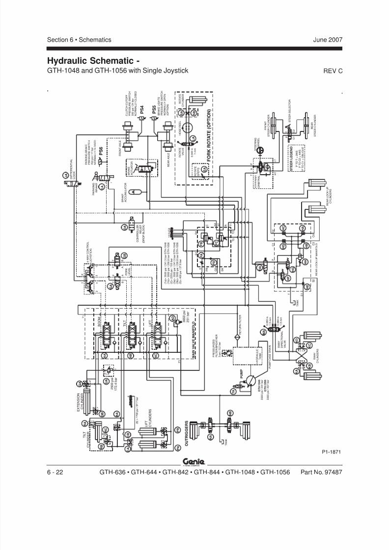
8/14/2019 Genie Manual de Servicio Gth-844
http://slidepdf.com/reader/full/genie-manual-de-servicio-gth-844 192/196
REV C
Section 6 • Schematics June 2007
6 - 22 GTH-636 • GTH-644 • GTH-842 • GTH-844 • GTH-1048 • GTH-1056 Part No. 97487
Hydraulic Schematic -GTH-1048 and GTH-1056 with Single Joystick
P1-1871
G T H - 1 0 4 8
G T H - 1 0 5 6
3 5 0 0
p s
i / 2 4 1
b a r
3 0 0 0
p s
i / 2 0 7
b a r
T
A
P
3 2
1
C L U T C H C U T O F F
P R E S S U R E S W I T
C H
3 5 0
p s
i / 2
4 b
a r
N O R M A L L Y
C L O S
E D
B R A K E L I G H T S
P R E S S U R E S W I T C H
N O R M A L L Y
O P E N
( O P T I O N )
P A
R K I N G
B R A K E
D I F F E R E N T I A L
L O C K
P A R K I N G B R A K E
P R E S S U R E S W I T C H
2 5 0
p s
i / 1
7 b
a r
N O R M A L L Y
C L O S E D
R E A R A X L E
B R A K E
A C C U M U
L A T O R
F R O N T
A X L E
0 . 0
4 0
i n
1 m
m
R O T A T E
V A L V E
S B
S A
L A
R O T A T
E
C Y L I N D E R
H O S E R E E L
F O R K
R O T A T E
( O P T I O N )
E A
R O T A T E
S P E E D
C O N T R O L L E R
R E L I E F
( D R O P B L O C K )
S T E E R I N G
O R B I T R A L
S T E E R I N G
W H E E L
F R O N T
S T E E R C Y L I N D E R
R E A R
S T E E R C Y L I N D E R
S T E E R S E L E C T O R
R T
L T
P
A
T
P
T
C 1
C 2
P T
O T
= 2
W S
P T
O C 2
= 4
W S
P T
O C 1
= O
B L I Q U E
S T E E R
L E G E N D
R E A R L O C K
- U P
C Y L I N D E R S
C 4
C 1
C 3
B
S 1
C 2
T A N K
S 2
T
P
S W A Y
C Y L I N D E R S
0 . 0
6 0
i n
1 . 5 m
m
0 . 0
6 0
i n
1 . 5 m
m
S W A Y
D I R E C T I O N A L
V A L V E
R E T U R N F I L T E R
P R E S S U R I Z E D
F I L T E R / B R E A T H E R
3 p
s i
/ 0
. 2 b
a r
H Y D R A U L I C
T A N K
P U M P
C A S E D R A I N
T A N K
O U T R I G G E R S
L I F T
C Y L I N D E R
S
T I L T
C Y L I N D E R
E X T E N
S I O N
C Y L I N D E R
M A I N
V A L V E M A N I F O L D
P 1
T 1
3 6 5 0
p s
i
2 5 1
b a r
B O O M
T I L T
L I F T
4
2
3
1
P
T
P
T
P
T
A
B
A
B 4 - W
A Y
C O N T R O L
( J O Y S T I C K )
S P R
B K
G 3
G 4
C R S T
G 2
T 1
T 2
T 3
G 1
( 1 a
) = 3
5 0 0
p s
i / 2
4 1
. 3 b
a r
G T H
- 1 0 4 8
( 1 b ) =
3 0 0 0
p s
i / 2
0 6
. 8 b
a r
G T H
- 1 0 5 6
( 2 ) =
2 2 5 0
p s
i / 1
5 5
b a r
( 5 ) =
4 0 0
p s
i / 2
7 . 6 b
a r
( 3 a
) = 3
5 0 0
p s
i / 2
4 1
. 3 b
a r
G T H
- 1 0 4 8
( 3 b ) =
3 0 0 0
p s
i / 2
0 6
. 8 b
a r
G T H
- 1 0 5 6
1 2 3
6 5 4
6
( 6 )
= 1 2 0 0 p s
i / 8
2 . 7
b a r
1 2
R E A R L O C K
- U P M A N I F O L D
A A
A B
A C
A D
C B
C A
D A
F A
F B F
C
F D
G A
G B
I A
J A B
R A K E
A C T U A T O R
K D
K A
K B
K C
M A
P B
P A
Q
A
Q B
B A
R A
R B
R C
H C
H B
H D
H F
H G
H H
H A
H E
F O R K
L E V E L
P S 4
P S 5
P S 6
N B
N A
O A
U A
2 5 0
0 p
s i
1 7 2 . 4
b a r P
U M P
T A

8/14/2019 Genie Manual de Servicio Gth-844
http://slidepdf.com/reader/full/genie-manual-de-servicio-gth-844 193/196
REV A
Section 6 • SchematicsJune 2007
Part No. 97487 GTH-636 • GTH-644 • GTH-842 • GTH-844 • GTH-1048 • GTH-1056 6 - 23
Hydraulic Schematic -GTH-1048 and GTH-1056 with Dual Joysticks
P1-1871
G T H - 1 0 4 8
G T H - 1 0 5 6
3 5 0 0
p s
i / 2 4 1
b a r
3 0 0 0
p s
i / 2 0 7
b a r
T
A
P
3 2
1
C L U T C H C U T O F F
P R E S S U R E S W I T
C H
3 5 0
p s
i / 2
4 b
a r
N O R M A L L Y
C L O S
E D
B R A K E L I G H T S
P R E S S U R E S W I T C H
N O R M A L L Y
O P E N
( O P T I O N )
P A
R K I N G
B R A K E
D I F F E R E N T I A L
L O C K
P A R K I N G B R A K E
P R E S S U R E S W I T C H
2 5 0
p s
i / 1
7 b
a r
N O R M A L L Y
C L O S E D
R E A R A X L E
B R A K E
A C C U M U
L A T O R
F R O N T
A X L E
0 . 0
4 0
i n
1 m
m
R O T A T E
V A L V E
S B
S A
L A
R O T A T
E
C Y L I N D E R
H O S E R E E L
F O R K
R O T A T E
( O P T I O N )
E A
R O T A T E
S P E E D
C O N T R O L L E R
R E L I E F
( D R O P B L O C K )
S T E E R I N G
O R B I T R A L
S T E E R I N G
W H E E L
F R O N T
S T E E R C Y L I N D E R
R E A R
S T E E R C Y L I N D E R
S T E E R S E L E C T O R
R T
L T
P
A
T
P
T
C 1
C 2
P T
O T
= 2
W S
P T
O C 2
= 4
W S
P T
O C 1
= O
B L I Q U E
S T E E R
L E G E N D
R E A R L O C K
- U P
C Y L I N D E R S
C 4
C 1
C 3
B
S 1
C 2
T A N K
S 2
T
P
S W A Y
C Y L I N D E R S
R E T U R N F I L T E R
P R E S S U R I Z E D
F I L T E R / B R E A T H E R
3 p
s i
/ 0
. 2 b
a r
H Y D R A U L I C
T A N K
P U M P
C A S E D R A I N
T A N K
O U T R I G G E R S
L I F T
C Y L I N D E R
S
T I L T
C Y L I N D E R
E X T E N
S I O N
C Y L I N D E R
M A I N
V A L V E M A N I F O L D
P 1
T 1
3 6 5 0
p s
i
2 5 1
b a r
B O O M
T I L T
L I F T
S P R
B K
G 3
G 4
C R S T
G 2
T 1
T 2
T 3
G 1
( 1 a
) = 3
5 0 0
p s
i / 2
4 1
. 3 b
a r
G T H
- 1 0 4 8
( 1 b ) =
3 0 0 0
p s
i / 2
0 6
. 8 b
a r
G T H
- 1 0 5 6
( 2 ) =
2 2 5 0
p s
i / 1
5 5
b a r
( 5 ) =
4 0 0
p s
i / 2
7 . 6 b
a r
( 3 a
) = 3
5 0 0
p s
i / 2
4 1
. 3 b
a r
G T H
- 1 0 4 8
( 3 b ) =
3 0 0 0
p s
i / 2
0 6
. 8 b
a r
G T H
- 1 0 5 6
1 2 3
6 5 4
6
( 6 )
= 1 2 0 0 p s
i / 8
2 . 7
b a r
1 2
R E A R L O C K
- U P M A N I F O L D
A A
A B
A C
A D
C B
C A
D A
F A
F B F
C
F D
I A
J A B
R A K E
A C T U A T O R
K D
K A
K B
K C
P B
P A
Q
A
Q B
B A
R A
R B
R C
H C
H B
H D
H F
H G
H H
H A
H E
P S 4
P S 5
P S 6
N B
N A
O A
U A
2 5 0
0 p
s i
1 7 2 . 4
b a r
4
2
3
1
P
T
4 - W
A Y
C O N T R
O L
( J O Y
S T I C K
)
M A
0 . 0
6 0
i n
1 . 5 m
m
0 . 0
6 0
i n
1 . 5 m
m
S W A Y
D I R E C T I O N A L
V A L V E
4
2
3
1
P
T
4 - W
A Y
C O N T R
O L
( J O Y
S T I C K
)
V A
P U M P
T A

8/14/2019 Genie Manual de Servicio Gth-844
http://slidepdf.com/reader/full/genie-manual-de-servicio-gth-844 194/196
Section 6 • Schematics June 2007
6 - 24 GTH-636 • GTH-644 • GTH-842 • GTH-844 • GTH-1048 • GTH-1056 Part No. 97487
This page intentionally left blank.

8/14/2019 Genie Manual de Servicio Gth-844
http://slidepdf.com/reader/full/genie-manual-de-servicio-gth-844 195/196
8/14/2019 Genie Manual de Servicio Gth-844
http://slidepdf.com/reader/full/genie-manual-de-servicio-gth-844 196/196
S e r v i c e M a n u a l
G T H - 6 4 4 • G
T H - 8 4 4 • G T H - 1 0 5 6
G T H - 6 3 6 • G
T H - 8 4 2 • G T H - 1 0 4 8
( G ( G ( G ( G ( G


