
GeneralSpecifications
GS12D7B5-E-A
Model SC450GConductivity / Resistivity ANALYZER
The new EXAxt Model 450 Analyzer series builds on the superior
functionality of the industry leading Yokogawa EXA series by enhancing
the EXA’s proven operation and application flexibility. The Model 450
series features a uniquely simple touch screen menu structure that offers
a choice of five different languages (English, French, German, Italian or Spanish).
The SC450 provides the best accuracy in the industry resulting from
advanced temperature compensation functionality, preloaded calibration
standards and online cell and analyzer diagnostics to provide verifiable
results.
In addition, the EXAxt SC450 offers full functionality including PID control
on either of the two mA output(s) or on any of the four independent
contact output(s). A digital HART signal is also superimposed on mA1.
The contact outputs can be selected as pulse frequency controlled or
pulse length controlled contact function to control chemical metering
pumps or solenoid valves. This information can be used to generate
additional current and contact outputs in the HIM monitor and in
maintenance optimization programs like PRM or AMS.
The EXAxt SC450 is a universal analyzer accepting sensors with cell
constants ranging from 0.005 to 50/cm; 2-electrode sensors as well as
4-electrode sensors and 5 different temperature compensating elements
for accurate temperature compensation.
The SC450 offers ultra pure water compensation for demineralized water
(default: NaCl), for Steam, Condensate and Boiler Water analysis (Cation
Conductivity, Ammonia and Morpholine Conductivity). The SC450 also
offers Matrix compensation and output linearization for more accurate
analysis of strong acids in the Pharmaceutical industry. The capability to
address the functional requirements of USP chapter 645, first published in
USP23, is also implemented.
The EXAxt 450 series provides a truly unique Human Machine Interface.
The high resolution graphical display and touch screen operation provides
all information clearly visible and easily accessible to the operator. Simply
select the language of choice and on screen instructions assure that the
best configuration for the application is obtained.
Features• Unique touch screen operation with menu structure in 5 languages.
• Enhanced diagnostics, process treanding graphics and
on-screen logbook for data storage
• Two mA-outputs and four SPDT relay contacts with display indicators
• Hart® Communications
• FM Class 1, Div.2, Group ABCD, T6 for Ta-20 to 55°C
• IP66/NEMA4X 1/2 DIN enclosure for Field Mounting and Panel Mounting
• Advanced Process Temperature Compensation
• Cell fouling monitoring
Sensors Cables Fittings Transmitters Accessories
System Configuration
Transmitters
上海晖盈实业有限公司 TEL:021-61724428 FAX:021-54795382 Email:[email protected]

2
General Specifications of EXAxt SC450
A) Input specifications : Two or four electrode measurement with square
wave excitation, using max 60m (200ft) cable
(WU40/WF10 and cell constants from 0.005 to
50.0cm-1
B) Input ranges
Conductivity : 0.000µS/cm - 200mS/cm
Minimum : 1µS x C (underrange 0.00 µS x C)
Maximum : 200mSxC (overrange 2000 ms x C)
Resistivity : 0.0Ωxcm - 1000MΩ x cm
Minimum : 5Ω/C (underrange 0.0 Ω/C)
Maximum : 1MΩ / C (overrange 100 MΩ/C)
Temperature
Pt1000 : -20 to 250ºC (0 - 500°F)
Pt100 : -20 to 200ºC (0 - 400°F)
Ni100 : -20 to 200ºC (0 - 400°F)
NTC 8k55 : -10 to 120ºC (0 - 250°F)
Pb36 (JIS NTC 6k) : -20 to 120ºC (0 - 250°F)
C) Accuracy
Conductivity/Resistivity : ≤ 0.5 % of reading
Temperature : ≤ 0.3 ºC (≤ 0.4 ºC for Pt100)
mA output circuits : ≤ 0.02 mA.
Ambient temperature : 500ppm/°C
Influence : ±0.05% / ºC.
Step response : < 4 sec for 90% (for a 2 decade step)
D) Transmission signals
General : Two isolated outputs of 4-20 mA. DC with
common negative. Maximum load 600Ω. Bi-
directional HART® digital communication,
superimposed on mA1 (4-20mA) signal.
Control functions : Linear or 21-step table table for Conductivity/
Resistivity, concentration or temperature.
- PID control.
(3.6mA) to signal failure acc.
NAMUR NE43.
- Adjustable damping
- Expire time
Hold : The mA-outputs are held at the last/fixed
value during calibration/commissioning
E) Contact outputs
General : Four SPDT relay contacts with display
indicators. Contacts outputs configurable for
hysteresis and delay time.
Switch capacity : Maximum values 100 VA, 250 VAC, 5 Amps.
Maximum values 50 Watts, 250 VDC, 5 Amps.
Status : High/Low process alarms, selected from
conductivity, resistivity, concentration or
temperature. Configurable delay time and hysteresis.
PID duty cycle or pulsed frequency control.
FAIL alarm
Control functions : On/Off
: Adjustable damping
: Expire time
Hold : Contact can be used to signal the Hold situation.
F) Contact input : Remote range switching to 10 times the
programmed range.
Contact open : If impedance > 100kΩ: Range 1
Contact closed : If impedance < 10 Ω: Range 2 (10x Range 1)
G) Temperature compensation
: Automatic or manual, for temperature ranges
mentioned under C (inputs).
Reference temp. : programmable from 0 to 100°C or 30 - 210°F
(default 25°C).
H) Compensation algorithm
: According IEC 746-3 NaCl tables (default). Two
independent user programmable temperature
coefficients, from 0% to 3.5% per °C (°F) by
adjustment or calibration.
Matrix compensation : With conductivity function of concentration and
temperature. Choice out of 13 preprogrammed
matrixes and 2 100-point user-programmable matrices.
I) Calibration : Semi-automatic calibration using pre-
configured OIML (KCI) buffer tables, with
automatic stability check. Manual adjustment to
grab sample.
J) Logbook : Software record of important events and
diagnostic data readily available in the display
or through HART.
K) Display : Graphical Quarter VGA (320 x 240 pixels) LCD
with LED backlight and touchscreen. Plain
language messages in English, German,
French, Spanish, and Italian.
L) Shipping details
Package size : 293 x 233 x 230 mm (L x W x D)
(11.5 x 9.2 x 9.1 inch).
Package weight : app. 2.5 kg (5.5lbs).
M) Housing : Cast aluminum case with chemically resistant
coating, cover with flexible polycarbonate window.
The colour of the case and cover is silvergrey.
Cable entry via six M20 polyimide glands. Cable
terminals are provided for up to 2.5 mm2 finished
wires. Weather resistant to IP66 and NEMA4X
standards. Pipe, wall or panel mounting, using
optional hardware.
N) Power supply : 85-265 VAC (±10%). Max 10VA, 47-63Hz,
9.6-30 VDC (±10%), max 10W.
O) Regulatory compliance
EMC : Meets directive 89/336/EEC
Emission conform EN 55022 class A
Immunity conform IEC 61326-1.
Low Voltage : Meets directive 73/23/EEC
Conform IEC 61010-1, UL61010C-1 and CSA 22.2 No.1010.1,
Installation category II, Pollution degree 2
Certification for cCSAus, Kema Keur and Geprufte Sicherheit
FM Class 1, Div. 2, Group ABCD, T6 forTa -20 to 55°C
P) Environment and operational conditions
Ambient temperature :-20 to +55°C
Storage temperature :-30 to +70°C
上海晖盈实业有限公司 TEL:021-61724428 FAX:021-54795382 Email:[email protected]

3
Humidity : 0 to 90% RH (non-condensing)
Data protection : EEPROM for configuration data and logbook.
Lithium cell for clock.
Watchdog timer : Checks microprocessor.
Power down : Reset to measurement.
Automatic safeguard : Auto return to measuring mode when
touchscreen is untouched for 10 min.
Display and Operating Interface
The Display is a backlit graphical display with QVGA resolution. Operation
is done by a touch screen. Graphical keys on the right and other area’s of
the touch screen respond to contact as virtual push buttons.
Main screen
The main screen displays:
1 The primary variable in large font (user selectable)
2 Other process variable(s) in small font
3 Unit symbols
4 Tagnumber (user programmable)
5 Process description (user programmable)
6 Status of alarm output(s)
7 Status indicator during HOLD and WASH situation
8 Main Function keys
Trend screen
The trend screen displays:
1 Time scale. User selectable (between 15 minutes and 1 week)
2 PV scale. User selectable
3 TAG number
4 Actual Primary Value
5 Average, maximum and minimum Primary Value in this
interval (time scale / 51)
The zoom screen displays an simple graphic representation of the
output functions. When “next” is pressed it will give access to the logbook data.
Status screen
The Status screen gives access to diagnostic information with regards to
analyzer or sensors.
No malfunction detected
Soft alarm detected. Maintenance is recommended for best accuracy
Hard alarm is detected indicating malfunction that is critical for
good analysis. When this key is pressed details are displayed
with regards to detected malfunction and troubleshooting
guidelines are displayed to resolve the malfunction.
Maintenance screen
The maintenance screen gives access to calibration, commissioning and
setup of the instrument. These levels can be protected by passwords.
Example
-Go to graph screen
-Go to detail screen
-Go to info screen
-Go to setup screen
Maximum
Minimum
Minimum
Maximum
Average
Live reading
SC
SC
T
120.0
90.0
60.0
30.0 109.3 µS/cm
450
Zoom screen
上海晖盈实业有限公司 TEL:021-61724428 FAX:021-54795382 Email:[email protected]

Functionality Characteristics
Safe operation
EXAxt450 features BURN-OUT functionality according to NAMUR
Recommendation 43. This document recommends to use the mA Output for
fault detection by controlling the mA output in the following way:
4-20 mA: scaled to measuring range
3.8-4 mA for underflow detection
20- 20.5 mA for overflow detection
=< 3.6 mA for fault detection
=> 21 mA for fault detection
Input circuitry
The conductivity is measured with a square wave AC signal across the
sensor with a frequency that is automatically adapted to the conductivity
value to minimize the influence of system capacitance and electrode
polarization. The conductivity is measured with 4-wire method to eliminate
the influence of cable length. This results in an accurate measurement over
a wider range of conductivity values using fewer cell constants.
Process Temperature Compensation
EXAxt 450 offers automatic temperature compensation and ensures full
compatibility with most commercially available conductivity sensors.
Selection is possible out of five different temperature sensing elements. All
elements have been calibrated during initialization of the analyzer. The
default configuration of the SC450 uses Pt1000 RTD for temperature compensation.
The temperature compensator is used to correct for the influence of
temperature on the conductivity of the process fluid. The analyzer readings
are at reference temperature: 25°C unless programmed otherwise.
The default temperature compensation follows the IEC 746-2 compensation
algorithm for diluted solutions of NaCl in water. This default mode(NaCl)
also incudes compensation for the temperature influence on the
dissociation of water molecules. This makes the default compensation
mode ideal for salt solutions from ultra pure water up to concentrated salt
solutions.
SC450 offers three additional modes for advanced temperature compensation
in processes where NaCl compensation does not offer the required accuracy:
1. Linear temperature coefficient stying
2. Matrix temperature compensation
Linear temperature coefficient
This function is used when the water chemistry is unknown. Therefore the
temperature coefficient is determined empirically by taking a sample,
reading conductivity and temperature, at two different temperatures. The TC
to be programmed is as % per °C. This coefficient is calculated from two
uncompensated measurements at different temperatures and can be
calculated with the following equation: ((SC1-SC2)/(T1-T2))x100/SC2 in
which (T2, SC2) is the measurement at reference temperature.
Matrix temperature compensation
This function is used when the empirical method has shown that the temperature
coefficient varies within the measuring range of the analyzer. Then a Matrix is built of
100 points, where the conductivity of 10 different samples is recorded for 10 different
temperatures.
Matrix temperature compensation
The SC450 is equipped with a matrix type algorithm (conductivity as a
function of concentration and temperature) for accurate temperature
compensation in various applications.
These are:
1. Ammonia in water: 0 - 50 ppb@0 - 90°C
(boiler feed water, condensate)
2. Ammonia in water: 15 - 30% @ 10 - 50°C
3. Morpholine in water: 0 - 500 ppb @ 0 - 90°C
(boiler feed water, condensate)
4. Sulfuric Acid in water: 0 - 27% @ 0 - 100°C
5. Sulfuric Acid in water: 39 - 85% @ - 18 - 116°C
6. Sulfuric Acid in water: 93 - 100% @ 10 - 90°C
7. Sodium Hydroxide in water: 0 - 15% @ 0 - 100°C
8. Sodium Hydroxide in water: 25 - 50% @ 0 -80°C
9. Hydrochloric Acid in water: 0 - 200 ppb @ 0 - 100°C
(Cation conductivity)
10. Hydrochloric Acid in water: 0 - 18% @ 10 - 65°C
11. Hydrochloric Acid in water: 24 - 44% @ -20 - 65°C
12. Nitric Acid in water: 0 - 25% @ 0 - 80°C
13. Nitric Acid in water: 35 - 88% @ -16 -60°C
In addition a free programmable matrix can be selected for applications not
covered by these standard ones. Measurement outside the range of the matrix
is possible, but can result in inaccuracies dependent on the chemistry of the
electrolyte solution.
0
50
100
150
200
250
300
350
400
450
500
0ºC 25ºC 50ºC 75ºC 100ºC
x
x
x
x
x
1%
2%
3%
4%
5%
mS
/cm
Temperature (Celsius)
Sodium hydroxide(0 - 5% at 0 - 100ºC)
0,0
0,5
1,0
1,5
2,0
2,5
3,0
3,5
mS/cm
上海晖盈实业有限公司 TEL:021-61724428 FAX:021-54795382 Email:[email protected]
5
WFI monitoring according to USP 645 directives.
First published in USP23 is the directive for on-line monitoring of water for
injection using Conductivity Analyzers. In this standard the purity of the
water is classified in 3 levels, of which the first level is monitored by
Conductivity Analysis. If the Conductivity exceeds the limit, then the user
must perform laboratory analysis to verify the quality of the WFI. SC450 has
the limits of USP built in the firmware and as soon as the water quality does
not meet the requirement of step 1, a fault message is generated: this
information can be transmitted through HART, contact output or High/Low
mA output according to NAMUR Recommendation 43. It is also possible to
program a contact output to close when a present safety margin is exceeded.
The USP functionality is independent of the chosen conductivity range for
the mA outputs, The functionality is active in both Conductivity and Resistivity mode.
Electrode selection
In order to make precise conductivity measurements, there are a number of
prerequisites. Most important is the selection of suitable sensors. Special
attention should be paid to the choice of the sensors to ensure compatibility
with both the chemical composition and the specific conductivity of the fluid
to be measured. Other Yokogawa specification sheets cover the choice of
sensors and holders, and any Yokogawa sales office can provide expert advice.
Measuring range as function of the cell constant
Note: With 2-electrode systems, polarization
may decrease the conductivity value at
higher concentrations. Applications using
highly conductivity fluids, inductive conductivity
measurement should be considered as an
alternative because of lower maintenance
requirements.
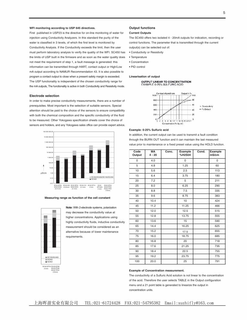
Output functions
Current Outputs
The SC450 offers two isolated 4 - 20mA outputs for indication, recording or
control functions. The parameter that is transmitted through the current
output(s) can be selected out of:
• Conductivity or Resistivity
• Temperature
• Concentration
• PID control
Linearisation of output
Example: 0-25% Sulfuric acid
In addition, the current output can be used to transmit a fault condition
through the BURN OUT function and it can maintain the last measured
value prior to maintenance or a fixed preset value using the HOLD function.
Example of Concentration measurement.
The conductivity of a Sulfuric Acid solution is not linear to the concentration
of the acid. Therefore the user selects TABLE in the Output configuration
menu and a 21 point table is generated to linearize the output in
concentration units.
SC42-SP34SX42-SX34(0.01/cm)
SC4A-002(0.02/cm)
SC42-SP24SX42-SX24
(0.1/cm)
SC4A-010(0.1/cm)
SC42-EP14(1/cm)
SC42-EP15(D)(1/cm)
SC42-EP04SC42-FP04SC42-TP04
(10/cm)
SC402/SC202/SC150/SC450DC402
100 000 000.00
10 000 000.00
1 000 000.00
100 000.00
10 000.00
1 000.00
100.00
10.00
1.00
0.10
0.01
µS/cm
S
SC42-EP18(1/cm)
SC42-EP08SC42-FP08SC42-TP04
(10/cm)
SC150/SC450
SC202
SC402
CodeOutput
MA4 - 20
Conc. Example%H2S04
Cond. ExamplemS/cm
0 4.0 0 0
5 4.8 1.25 60
10 5.6 2.5 113
15 6.4 3.75 180
20 7.2 5 211
25 8.0 6.25 290
30 8.8 7.5 335
35 9.6 8.75 383
40 10.4 10 424
45 11.2 11.25 466
50 12.0 12.5 515
55 12.8 13.75 555
60 13.6 15 590
65 14.4 16.25 625
70 15.2 17.5 655
75 16.0 18.75 685
80 16.8 20 718
85 17.6 21.25 735
90 18.4 22.5 755
95 19.2 23.75 775
100 20.0 25 791
上海晖盈实业有限公司 TEL:021-61724428 FAX:021-54795382 Email:[email protected]
6
Contact Outputs
The SC450 offers four SPDT contacts outputs. All contact outputs can be
configured for Alarm and Control functions. Contact S1, S2 and S3 are in
powered condition when the setpoint is exceeded. These contacts are
normally used for HI, LO Alarm or Control functions. Contact S4 is in alarm
condition when the power is down. This FAIL-SAFE contact is normally used to
signal a FAIL situation.
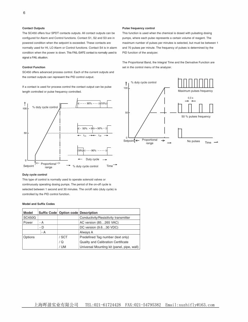
Control Function
SC450 offers advanced process control. Each of the current outputs and
the contact outputs can represent the PID control output.
If a contact is used for process control the contact output can be pulse
length controlled or pulse frequency controlled.
Duty cycle control
This type of control is normally used to operate solenoid valves or
continuously operating dosing pumps. The period of the on-off cycle is
selected between 1 second and 30 minutes. The on/off ratio (duty cycle) is
controlled by the PID control function.
Model and Suffix Codes
Pulse frequency control
This function is used when the chemical is dosed with pulsating dosing
pumps, where each pulse represents a certain volume of reagent. The
maximum number of pulses per minutes is selected, but must be between 1
and 70 pulses per minute. The frequency of pulses is determined by the
PID function of the analyzer.
The Proportional Band, the Integral Time and the Derivative Function are
set in the control menu of the analyzer.
90% 10%
100
50
0
ont toff
90%10%
50% 50%
Model Suffix Code Option code Description
SC450G Conductivity/Resisitivity transmitter
Power - A AC version (85…265 VAC)
- D DC version (9.6…30 VDC)
- A Always A
Options / SCT Predefined Tag number (text only)
/ Q Quality and Calibration Certificate
/ UM Universal Mounting kit (panel, pipe, wall)
100
50
0
0.3 s
% duty cycle control
Proportionalrange
Duty cycle
TimeSetpoint % duty cycle control
TimeSetpoint Proportional
range
% duty cycle control
No pulses
50 % pulses frequency
Maximum pulses frequency
上海晖盈实业有限公司 TEL:021-61724428 FAX:021-54795382 Email:[email protected]

7
Connection Diagram
High Voltage Signal
mA OutputsPowerSupply
RelayContacts
Sensor Inputs
POWER SUPPLY OUTPUTS
100-240VAC/10VA
CONTACTS
INPUTS
NC
C
NO
NC
C
NO
S3
S4
Temp
mA1
mA2
Shield
L
N
1
2
3
51
52
53
71
72
73
+-
11
12
13
14
15
16
+-
+-
61
62
65
66
63
21
22
Input contactNC
C
NO
NC
C
NO
S1
S2
31
32
33
41
42
43
v-
i-
v+
i+
Wiring Diagram
Dimension and Mounting
80(3.15")
2x ø6.5(0.26")
4x ø10(0.4")
200(7.87")
70(2.75")
141.5(5.57")
2" ND. pipe
pipe mounting(horizontal)
pipe mounting(vertical)
wall mounting
OPTION /UM: Universal pipe/wall/panel mounting kit
上海晖盈实业有限公司 TEL:021-61724428 FAX:021-54795382 Email:[email protected]
8
144(5.67)14
4(5.
67")
24.5
(1")
114.
5(4.
51")
27(1.06")
min.185 (7.25)
min
.195
(7.7
5)
138(5.43)
138(5.43)
M6
M6
M5
138
138
80
80
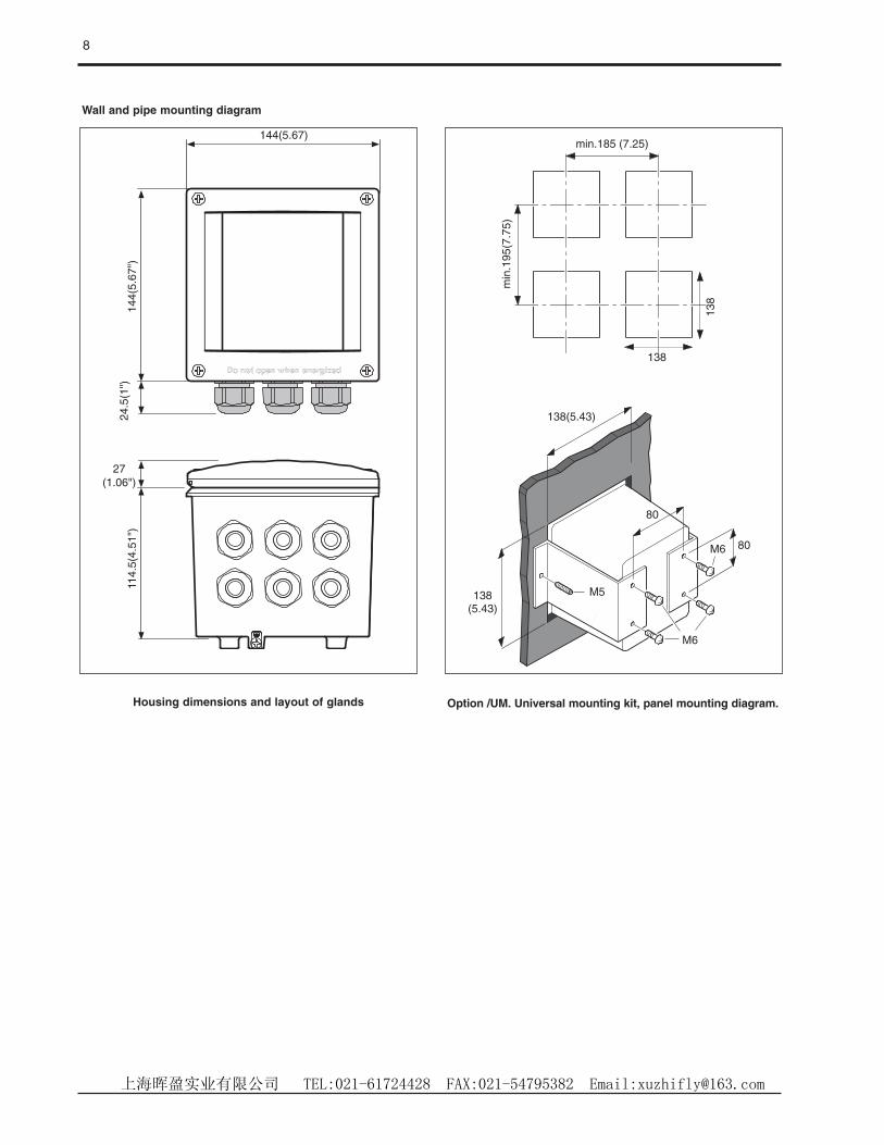
Wall and pipe mounting diagram
Housing dimensions and layout of glands Option /UM. Universal mounting kit, panel mounting diagram.
上海晖盈实业有限公司 TEL:021-61724428 FAX:021-54795382 Email:[email protected]


![D y Ì7 $Î + 6SWZö1*1n >J>E>@>R>Ob Ê]vSUb8r >D>P>C>L>Q æ/² %¼ î ¥#.I bs^I b p_c >J>E>@>RWZ 1>= \ î Z8 v8 \ î8rM öb ¨ ] ö_X8Z](https://cdn.vdocuments.us/doc/165x107/5f08bc457e708231d42377df/d-y-oe7-6swz-11n-jerob-vsub8r-dpclq.jpg)

