GeneralSpecifications
<<Contents>> <<Index>>
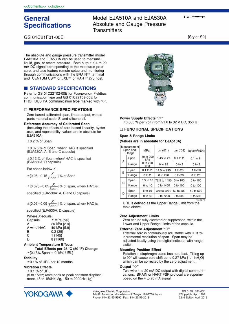
The absolute and gauge pressure transmitter modelEJA510A and EJA530A can be used to measureliquid, gas, or steam pressure. Both output a 4 to 20mA DC signal corresponding to the measured pres-sure, and also feature remote setup and monitoringthrough communications with the BRAIN™ terminaland CENTUM CS™ or µXL™ or HART® 275 host.
� STANDARD SPECIFICATIONSRefer to GS 01C22T02-00E for FOUNDATION Fieldbuscommunication type and GS 01C22T03-00E forPROFIBUS PA communication type marked with “�”.
� PERFORMANCE SPECIFICATIONSZero-based calibrated span, linear output, wettedparts material code ‘S’ and silicone oil.
Reference Accuracy of Calibrated Span(including the effects of zero-based linearity, hyster-esis, and repeatability, values are in absolute forEJA510A)
�0.2 % of Span
�0.075 % of Span, when/ HAC is specified(EJA530A: A, B and C capsule)
�0.12 % of Span, when/ HAC is specified(EJA530A: D capsule)
For spans below X,
�[0.05�0.15 ] % of Span
�[0.025�0.05 ] % of span, when/ HAC is
specified (EJA530A: A, B and C capsule)
�[0.03�0.09 ] % of span, when/ HAC is
specified (EJA530A: D capsule)
XSpan
XSpan
XSpan
Where X equals:Capsule X MPa {psi}A 20 kPa {2.9}A with/ HAC 40 kPa {5.8}B 0.2 {29}C 1 {145}D 8 {1160}
Ambient Temperature EffectsTotal Effects per 28 �C (50 �F) Change
�[0.15% Span � 0.15% URL]
Stability�0.1% of URL per 12 months
Vibration Effects�0.1 % of URL(5 to 15Hz; 4mm peak-to-peak constant displace-ment, 15 to 150Hz; 2g, 150 to 2000Hz; 1g)
Model EJA510A and EJA530AAbsolute and Gauge PressureTransmitters
Yokogawa Electric Corporation2-9-32, Nakacho, Musashino-shi, Tokyo, 180-8750 JapanPhone: 81-422-52-5690 Fax.: 81-422-52-2018
GS 01C21F01-00E
GS 01C21F01-00E©Copyright Apr. 199922nd Edition April 2012
Power Supply Effects “�”�0.005 % per Volt (from 21.6 to 32 V DC, 350 �)
� FUNCTIONAL SPECIFICATIONS
Span & Range Limits
(Values are in absolute for EJA510A)
A
B
MeasurementSpan and
Range
Span
Range
Span
Range
psi (/D1)
1.45 to 29
0 to 29
14.5 to 290
0 to 290
bar (/D3)
0.1 to 2
kgf/cm2(/D4)
0.1 to 2
0 to 2
1 to 20
0 to 20
0 to 2
1 to 20
0 to 20
MPa
10 to 200kPa
0 to 200kPa
0.1 to 2
0 to 2
72.5 to 14500.5 to 10
0 to 10C
Span
Range 0 to 1450
5 to 100
0 to 100
5 to 100
0 to 100
720 to 72005 to 50
0 to 50D
Span
Range 0 to 7200
50 to 500
0 to 500
50 to 500
0 to 500T01E.EPS
URL is defined as the Upper Range Limit from thetable above.
Zero Adjustment LimitsZero can be fully elevated or suppressed, within theLower and Upper Range Limits of the capsule.
External Zero Adjustment “�”External zero is continuously adjustable with 0.01 %incremental resolution of span. Span may beadjusted locally using the digital indicator with rangeswitch.
Mounting Position EffectRotation in diaphragm plane has no effect. Tilting upto 90� will cause zero shift up to 0.27 kPa {1.1 inH2O}which can be corrected by the zero adjustment.
Output “�”Two wire 4 to 20 mA DC output with digital communi-cations. BRAIN or HART FSK protocol are superim-posed on the 4 to 20 mA signal.
[Style: S2]
2
All Rights Reserved. Copyright © 1999, Yokogawa Electric Corporation
<<Contents>> <<Index>>
Failure AlarmOutput status at CPU failure and hardware error;
Up-scale: 110%, 21.6 mA DC or more (standard)Down-scale: -5%, 3.2 mA DC or less
-2.5%, 3.6 mA DC or less (Optionalcode /F1)
Note : Applicable for Output signal code D and E.
Damping Time Constant (1st order)The sum of the amplifier and capsule damping timeconstant must be used for the overall time constant.Amp damping time constant is adjustable from 0.2 to64 seconds.
Time Constant (approx. sec) 0.2
A, B, C, and DCapsule (Silicone Oil)
Ambient Temperature Limits (approval codes may affect limits)
-40 to 85 �C (-40 to 185 �F)-30 to 80 �C (-22 to 176 �F) with LCD Display
Process Temperature Limits(approval codes may affect limits)
-40 to 120 �C (-40 to 248 �F)
Ambient Humidity Limits5 to 100 % RH @ 40 �C (104 �F)
Maximum Overpressure
A 4 MPa abs{580 psia} 4 MPa {580 psig}B 4 MPa abs{580 psia} 4 MPa {580 psig}C 20 MPa abs{2900 psia} 20 MPa {2900 psig}D 60 MPa abs{8500 psia} 60 MPa {8500 psig}
EJA530AEJA510ACapsule Capsule
Working Pressure Limits (Silicone Oil)Maximum Pressure Limit
A 200 kPa abs{29 psia} 200 kPa {29 psig}B 2 MPa abs{290 psia} 2 MPa {290 psig}C 10 MPa abs{1450 psia} 10 MPa {1450 psig}D 50 MPa abs{7200 psia} 50 MPa {7200 psig}
EJA530AEJA510ACapsule Capsule
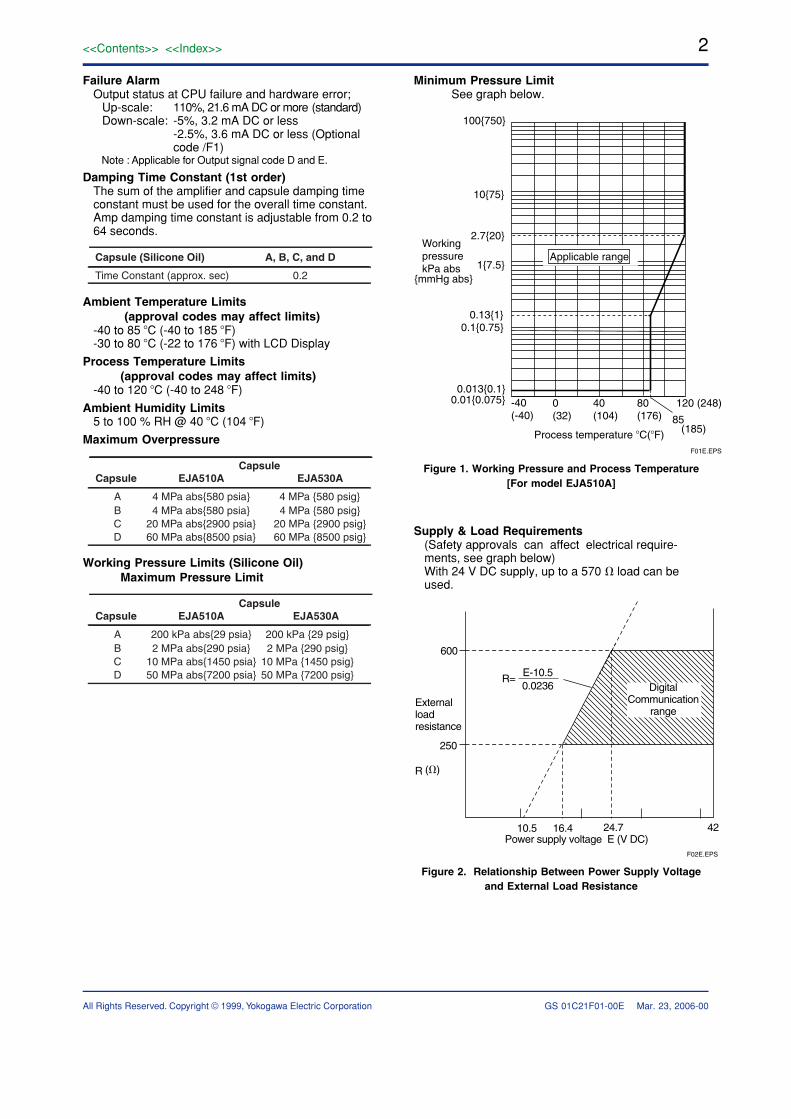
Minimum Pressure LimitSee graph below.
-40(-40)
0(32)
40(104)
80(176)
120 (248)
0.1{0.75} 0.13{1}
1{7.5}
100{750}
10{75}
2.7{20}
0.01{0.075} 0.013{0.1}
85 (185)
{mmHg abs}
WorkingpressurekPa abs
Applicable range
Process temperature �C(�F)F01E.EPS
Figure 1. Working Pressure and Process Temperature[For model EJA510A]
Supply & Load Requirements(Safety approvals can affect electrical require-ments, see graph below)With 24 V DC supply, up to a 570 � load can beused.
E-10.5 0.0236
(�)
Power supply voltage E (V DC)
600
250
R
10.5 16.4 24.7 42
Externalloadresistance
DigitalCommunication
range
R=
F02E.EPS
Figure 2. Relationship Between Power Supply Voltageand External Load Resistance
GS 01C21F01-00E Mar. 23, 2006-00

3<<Contents>> <<Index>>
All Rights Reserved. Copyright © 1999, Yokogawa Electric Corporation
Supply Voltage “�”10.5 to 42 V DC for general use and flameproof type10.5 to 32 V DC for lightning protector (Optional
code /A)10.5 to 30 V DC for intrinsically safe, Type n,
nonincendive, or non-sparking typeMinimum voltage limited at 16.4 V DC for digital
communications, BRAIN and HART
Load (Output signal code D and E)0 to 1335 � for operation250 to 600 � for digital communication
EMC Conformity Standards “�” , EN61326-1 Class A, Table2 (For use in industriallocations)EN61326-2-3
European Pressure Equipment Directive 97/23/ECSound Engineering Practice
With option code /PE3
Category III, Module H, Type of Equipment: PressureAccessory-Vessel, Type of Fluid: Liquid and Gas,Group of Fluid: 1 and 2
Communication Requirements “�”
BRAIN
Communication DistanceUp to 2 km (1.25 miles) when using CEV polyethyl-ene-insulated PVC-sheathed cables. Communicationdistance varies depending on type of cable used.
Load Capacitance0.22 �F or less (see note)
Load Inductance3.3 mH or less (see note)
Spacing from power line15 cm or more.
Input Impedance of communicating device10 k� or more at 2.4 kHz.
Note : For general-use and Flameproof type.For Intrinsically safe type, please refer to‘OPTIONAL SPECIFICATIONS.’
� PHYSICAL SPECIFICATIONS
Wetted Parts Materials:
Diaphragm and Process connectorRefer to ‘MODEL AND SUFFIX CODE.’
Non-wetted Parts Materials:
HousingLow copper cast-aluminum alloy with polyurethanepaint (Munsell 0.6GY3.1/2.0)
Degrees of ProtectionIP67, NEMA4X
Cover O-ringsBuna-N, fluoro-rubber (optional)
Data plate and tagSUS304 or SUS316 (option)
Fill FluidSilicone, Fluorinated oil (option)
Weight1.6 kg (3.5 lb) without integral indicator, mountingbracket.
ConnectionsRefer to the model code to specify the process andthe electrical connection type.
< Settings When Shipped > “�”
Tag NumberOutput ModeDisplay Mode
Operation Mode
Damping TimeConstant
As specified in order *1‘Linear’
‘2 sec.’
‘Normal’ unless otherwise specified in order
‘Linear’
Calibration Range Units
As specified in order
As specified in order
Selected from mmH2O, mmAq, mmWG, mmHg, Torr, Pa, hPa, kPa, MPa, mbar, bar, gf/cm2, kgf/cm2, inH2O, inHg, ftH2O, psi, or atm.(Only one unit can be specified)
Calibration Range
Higher Range Value
Calibration Range
Lower Range Value
T05E.EPS
*1: Up to 16 alphanumeric characters for BRAIN and8 characters for HART including ‘-’ and ‘.’ will beentered in the amplifier memory. If specified Tagincludes other characters than above, it will notbe entered in the amplifier memory.
GS 01C21F01-00E July 01, 2011-00

4
All Rights Reserved. Copyright © 1999, Yokogawa Electric Corporation
<<Contents>> <<Index>>
� MODEL AND SUFFIX CODES
� Model EJA510A and EJA530A
. . . . . . . . . . . . . . . . . . . .
. . . . . . . . . . . . . . . . . . . .
-D . . . . . . . . . . . . . . . . .
-E . . . . . . . . . . . . . . . . .
-F . . . . . . . . . . . . . . . . .
-G . . . . . . . . . . . . . . . . . A . . . . . . . . . . . . . . .
B . . . . . . . . . . . . . . . C . . . . . . . . . . . . . . .
D . . . . . . . . . . . . . . .
S# . . . . . . . . . . . . . .
H# . . . . . . . . . . . . . .
4 . . . . . . . . . . . . .
7 . . . . . . . . . . . . . 8 . . . . . . . . . . . . .
9 . . . . . . . . . . . . .
N . . . . . . . . . .
-0 . . . . . . . .
0 . . . . . .
2 . . . . . .
3 . . . . . .
4 . . . . . .
5 . . . . . .
7 . . . . . .
8 . . . . . .
9 . . . . . . A . . . . . . C . . . . . . D . . . . . . D . . . E . . . N . . .
E . .
F . .
L . .
N . .
Model Description
EJA510A EJA530A
Output Signal
Measurement span(capsule)
Wetted parts material *2
Process connection
Electrical connection
Integral indicator
Mounting bracket
Optional codes
Absolute pressure transmitterGauge pressure transmitter
4 to 20 mA DC with digital communication (BRAIN protocol)4 to 20 mA DC with digital communication (HART protocol, refer to GS 01C22T01-00E) Digital communication (FOUNDATION Fieldbus protocol, refer to GS 01C22T02-00E)
Digital communication (PROFIBUS PA protocol, refer to GS 01C22T03-00E)
10 to 200 kPa {0.1 to 2 kgf/cm2} {1.45 to 29 psi} {0.1 to 2 bar}0.1 to 2 MPa {1 to 20 kgf/cm2} {14.5 to 290 psi} {1 to 20 bar}0.5 to 10 MPa {5 to 100 kgf/cm2} {72.5 to 1450 psi} {5 to 100 bar}5 to 50 MPa {50 to 500 kgf/cm2} {720 to 7200 psi} {50 to 500 bar}
[Process Connection] [Diaphragm]SUS316L *4 Hastelloy C-276 *3 Hastelloy C-276 *3 Hastelloy C-276 *3
1/2 NPT female1/2 NPT male G 1/2 DIN 16 288 maleM20�1.5 DIN 16 288 maleAlways N
Always 0G1/2 female, one electrical connection 1/2 NPT female, two electrical connections without blind plug Pg 13.5 female, two electrical connections without blind plug M20 female, two electrical connections without blind plugG1/2 female, two electrical connections and a blind plug1/2 NPT female, two electrical connections and a blind plug Pg 13.5 female, two electrical connections and a blind plug M20 female, two electrical connections and a blind plugG1/2 female, two electrical connections and a SUS316 blind plug1/2 NPT female, two electrical connections and a SUS316 blind plugM20 female, two electrical connections and a SUS316 blind plugDigital indicatorDigital indicator with the range setting switch *1
(None)
SECC Carbon steel 2-inch pipe mountingSUS304 2-inch pipe mountingSUS316 2-inch pipe mounting(None)
/� Optional specification
�
�
�
Suffix Codes
T02E.EPS
The ‘�’ marks indicate the most typical selection for each specification. Example: EJA530A-DAS4N-02NN/�The ‘#’marks indicate the construction materials conform to NACE material recommendations per MR01-75. For the use ofSUS316 material, there may be certain limitations for pressure and temperature. Please refer to NACE standards for details.
*1: Not applicable for Output signal code F and G.*2: Users must consider the characteristics of selected wetted parts material and the influence of process fluids. The
use of inappropriate materials can result in the leakage of corrosive process fluids and cause injury to personneland/or damage to plant facilities. It is also possible that the diaphragm itself can be damaged and that material fromthe broken diaphragm and the fill fluid can contaminate the user's process fluids.Be very careful with highly corrosive process fluids such as hydrochloric acid, sulfuric acid, hydrogen sulfide,sodium hypochlorite, and high-temperature steam (150°C [302°F] or above). Contact Yokogawa for detailedinformation of the wetted parts material.
*3: Hastelloy C-276 or ASTM N10276.*4: SUS316L or ASTM grade 316L.
GS 01C21F01-00E Jul. 08, 2009-00

5<<Contents>> <<Index>>
All Rights Reserved. Copyright © 1999, Yokogawa Electric Corporation
� OPTIONAL SPECIFICATIONS (For Explosion Protected types “�”)For FOUNDATION Fieldbus explosion protected type, see GS 01C22T02-00E.
For PROFIBUS PA explosion protected type, see GS 01C22T03-00E.
Item Description Code
Factory Mutual (FM)
ATEX Intrinsically safe Approval *2 *3 *4
Applicable standard: EN50014, EN50020, EN50284 Certificate: KEMA 02ATEX1030X II 1G EEx ia IIC T4, Amb. Temp.: –40 to 60�C (–40 to 140�F) Ui=30 V, Ii=165 mA, Pi=0.9 W, Ci=22.5 nF, Li=730 �H
KS2
FM Intrinsically safe Approval *1 *3 *4
Applicable standard: FM3600, FM3610, FM3611, FM3810, ANSI/NEMA250 Intrinsically Safe for Class I, Division 1, Groups A, B, C & D, Class II, Division 1, Groups E, F & G and Class III, Division 1 Hazardous Locations. Nonincendive for Class I, Division 2, Groups A, B, C & D, Class II, Division. 2, Groups E, F & G, and Class III, Division 1 Hazardous Locations. Enclosure: “NEMA 4X”, Temp. Class: T4, Amb. Temp.: –40 to 60�C (–40 to 140�F) Intrinsically Safe Apparatus Parameters [Groups A, B, C, D, E, F and G] Vmax=30 V, Imax=165 mA, Pmax=0.9 W, Ci=22.5 nF, Li=730 �H [Groups C, D, E, F and G] Vmax=30 V, Imax=225 mA, Pmax=0.9 W, Ci=22.5 nF, Li=730 �H
FS1
ATEX Flameproof Approval *2 *4
Applicable standard: EN 60079-0, EN 60079-1 Certificate: KEMA 02ATEX2148 II 2G Ex d IIC T4, T5, T6 Amb. Temp.: T5; –40 to 80�C ( –40 to 176�F), T4 and T6; –40 to 75�C ( –40 to 167�F) Max. process Temp.: T4; 120�C (248�F), T5; 100�C (212�F), T6; 85�C (185�F)
KF21
FM Explosionproof Approval *1 *3 *4 Applicable standard: FM3600, FM3615, FM3810, ANSI/NEMA250 Explosionproof for Class I, Division 1, Groups B, C and D Dust-ignitionproof for Class II/III, Division 1, Groups E, F and G Hazardous (classified) locations, indoors and outdoors (NEMA 4X) Temperature class: T6 Amb. Temp.: –40 to 60�C (–40 to 140�F)
FF1
FU1Combined FF1 and FS1 *1 *3 *4
Combined KF21, KS2 and ATEX Type n *2 *3 *4
Type n Applicable standard: EN 60079-15, EN 60079-0 II 3G Ex nL IIC T4 Gc, Amb. Temp.: –30 to 60°C (–22 to 140°F) Ui=30 V DC, Ci=22.5 nF, Li=730 µH Dust [For combined with II 2G] Applicable standard: EN 61241-0, EN 61241-1 II 2D Ex tD A21 IP6X Max. surface Temp. for dust-proof : T85°C (Tamb: –40 to 75°C, Tp:85°C), T100°C (Tamb: –40 to 80°C, Tp:100°C), T120°C (Tamb: –40 to 75°C, Tp:120°C ) [For combined with II 1G] Applicable standard: EN 50281-1-1 II 1D maximum surface temperature T65°C (149�F) {Tamb.: 40°C (104�F)}, T85°C (185�F) {Tamb.: 60°C (140�F)}, T105°C (221�F) {Tamb.: 80°C (176�F)}
KU22
ATEX
T03-1E.EPS
*1: Applicable for Electrical connection code 2, 7 and C (1/2 NPT female).*2: Applicable for Electrical connection code 2, 4, 7, 9, C and D (1/2 NPT and M20 female).*3: Applicable for Output signal code D and E.
For intrinsically safe approval, use the safety barrier certified by the testing laboratories (BARD-400 is not applicable).*4: Lower limit of ambient temperature is –15˚C (5˚F) when /HE is specified.
GS 01C21F01-00E April 23, 2012-00

6
All Rights Reserved. Copyright © 1999, Yokogawa Electric Corporation
<<Contents>> <<Index>>
GS 01C21F01-00E July 01, 2011-00
Item Description Code
CSA Explosionproof Approval *1 *3 *4
Applicable standard: C22.2 No. 0, No. 0.4, No. 25, No. 30, No. 94, No. 142 Certificate: 1089598 Explosionproof for Class I, Division 1, Groups B, C and D Dustignitionproof for Class II/III, Division 1, Groups E, F and G Division2 ‘SEALS NOT REQUIRED’ , Temp. Class: T4, T5, T6 Encl Type 4x Max. Process Temp.: T4; 120�C (248�F), T5; 100�C (212�F), T6; 85�C (185�F) Amb. Temp.: –40 to 80�C (–40 to 176�F)Process Sealing Certification Dual Seal Certified by CSA to the requirement of ANSI/ISA 12.27.01 No additional sealing required. Primary seal failure annunciation: at the zero adjustment screw
CF1
Canadian Standards Association (CSA) CSA Intrinsically safe Approval *1 *3 *4
Applicable standard: C22.2 No. 0, No. 0.4, No. 25, No. 30, No. 94, No. 142, No. 157, No. 213 Certificate: 1053843 Class I, Groups A, B, C and D Class II and III, Groups E, F and G Encl Type 4x, Temp. Class: T4, Amb. Temp.: –40 to 60�C (–40 to 140�F) Vmax=30 V, Imax=165 mA, Pmax=0.9 W, Ci=22.5 nF, Li=730 �HProcess Sealing Certification Dual Seal Certified by CSA to the requirement of ANSI/ISA 12.27.01 No additional sealing required. Primary seal failure annunciation: at the zero adjustment screw
CS1
IECEx SU2
IECEx Intrinsically safe, type n and Flameproof Approval *3 *4 *5
Intrinsically safe and type n Applicable Standard: IEC 60079-0:2004, IEC 60079-11:1999, IEC 60079-15:2005, IEC 60079-26:2005 Certificate: IECEx KEM 06.0007X Ex ia IIC T4, Ex nL IIC T4 Enclosure: IP67 Amb. Temp.: –40 to 60�C (–40 to 140�F), Max. Process Temp.: 120�C (248�F) Electrical Parameters: [Ex ia] Ui=30 V, Ii=165 mA, Pi=0.9 W, Ci=22.5 nF, Li=730 �H [Ex nL] Ui=30 V, Ci=22.5 nF, Li=730 �HFlameproof Applicable Standard: IEC 60079-0:2004, IEC60079-1:2003 Certificate: IECEx KEM 06.0005 Ex d IIC T6...T4 Enclosure: IP67 Max.Process Temp.: T4;120�C (248�F), T5;100�C (212�F), T6; 85�C (185�F) Amb.Temp.: –40 to 75�C (–40 to 167�F) for T4, –40 to 80�C (–40 to 176�F) for T5, –40 to 75�C (–40 to 167�F) for T6
CU1Combined CF1 and CS1 *1 *3 *4
T03-2E.EPS
*1: Applicable for Electrical connection code 2, 7 and C (1/2 NPT female).*2: Applicable for Electrical connection code 2, 4, 7, 9, C and D (1/2 NPT and M20 female).*3: Applicable for Output signal code D and E.
For intrinsically safe approval, use the safety barrier certified by the testing laboratories (BARD-400 is not applicable).*4: Lower limit of ambient temperature is –15˚C (5˚F) when /HE is specified.*5: Applicable for Electrical connection code 2, 4, 7, C and D (1/2 NPT and M20 female).

7<<Contents>> <<Index>>
All Rights Reserved. Copyright © 1999, Yokogawa Electric Corporation
� OPTIONAL SPECIFICATIONS
T04E.EPS
PE3
Item Description Code
Painting *12Color change
Coating change
Lightning protector
High accuracy type *11
Calibration units *1
PR
X1
HAC
A
D1
D3
D4
(See Table for Span and Range Limits.)
Amplifier cover and terminal cover, Munsell 7.5 R4/14
P�Amplifier cover only
High accuracy
Epoxy resin-baked coating *15
Transmitter power supply voltage: 10.5 to 32 V DC (10.5 to 30 V DC for intrinsically safe type, 9 to 32 V DC for Fieldbus communication type.)Allowable current: Max. 6000 A (1�40 �s), Repeating 1000 A (1�40 �s) 100 times
P calibration (psi unit)
bar calibration (bar unit)
M calibration (kgf/cm2 unit )
Fast response *9 F1Update time: 0.125 secAmplifier damping time constant: 0.1 to 64 sec in 9 incrementsResponse time (with min. damping time constant): max. 0.3 sec
Oil-prohibited use
Mill Certificate M15Process connector
Stainless steel amplifierhousing *3
Amplifier housing material; SCS14A stainless steel (equivalent to SUS316 cast stainless steel or ASTM CF-8M) E1
Degrease cleansing treatment *15
Degrease cleansing treatment with fluorinated oil filled capsule. Operating temperature �20 to 80�C
K1
K2
Pressure test/Leak test Certificate *13
T05
T06
T07
T08
Nitrogen (N2) Gas or Water *8
Retention time: 10 minutes
Test Pressure: 200 kPa (2 kgf/cm2) *4
Test Pressure: 2 MPa (20 kgf/cm2) *5
Test Pressure: 10 MPa (100 kgf/cm2) *6
Test Pressure: 50 MPa (500 kgf/cm2) *7
Failure alarm down-scale *2
NAMUR NE43 compliant *2 *10
C1Output status at CPU failure and hardware error is –5%, 3.2 mA or less.
Fluoro-rubber O-ring HEAll O-rings of amplifier housing. Lower limit of ambient temperature: �15�C (5�F)
Data configuration at factory *16 CADescription into “Descriptor” parameter of HART protocol
C2
C3
Output signal limits: 3.8 mA to 20.5 mA
Failure alarm down-scale: output status at CPU failure and hardware error is –5%, 3.2 mA or less.
Failure alarm up-scale: output status at CPU failure and hardware error is 110%, 21.6 mA or more.
European Pressure Equipment Directive *14
PED 97/23/ECCategory: III, Module: H, Type of Equipment: Pressure Accessory-Vessel, Type of Fluid: Liquid and Gas, Group of Fluid: 1 and 2
Wired tag plate Stainless steel tag plate wired onto transmitter N4
*1: The unit of MWP (Max. working pressure) on the name plate of a housing is the same unit as specified by Option codeD1, D3 and D4.
*2: Applicable for Output signal code D and E. The hardware error indicates faulty amplifier or capsule.When combining with Option code F1, output status for down-scale is –2.5%, 3.6 mA DC or less.
*3: Applicable for Electrical connection code 2, 3, 4, A, C and D. Not applicable for Option code P� and X1.*4: Applicable for Capsule code A.*5: Applicable for Capsule code B.*6: Applicable for Capsule code C.*7: Applicable for Capsule code D.*8: Pure nitrogen gas or pure water is used for oil-prohibited use (Option code K1 and K2)*9: Applicable for Output signal code D and E. Write protection switch is attached for Output code E.*10: Not applicable for Option code C1.*11: Applicable for EJA530A. Refer to GS 01C21F01-02E.*12: Standard polyurethan painting can be used in acid atmosphere, whereas the epoxy resin-baked coating (Option code
X1) can be used in alkaline atmosphere. Anti-corrosion coating, the combination of polyurethan and epoxy resin-bakedcoating, is available by special order as sea water, alkaline, and acid resistant.
*13: The unit on the certificate is always kPa or MPa regardless of selection of option code D1, D3, or D4.*14: If compliance with category III is needed, specify this option code.*15: Not applicable for color change option.*16: Applicable for Output signal code E.
GS 01C21F01-00E July 01, 2011-00

8
All Rights Reserved. Copyright © 1999, Yokogawa Electric Corporation
<<Contents>> <<Index>>
� DIMENSIONS
� Model EJA510A and EJA530A
124(
4.88
)47
(1.8
5)
91(3.58)
44(1.73)
Adapter
Mounting bracket
110(4.33)
12 (0.47)
45 (1.77)
111(
4.37
)
Groundterminal
Zero adjustment
�78
(3.0
7)
� With Process Connection code 7Unit: mm(Approx. inch)
163(
6.41
)
� For Process Connection code 4
5(0.
19)
20(0
.78)
176(
6.92
)
� For Process Connection code 8 and 9
�6(0.23)
96(3.77) 41(1.61)12
7(5.
0)
170(
6.69
)Pipe(Open to atmosphere)*1
Conduit connection
Shrouding bolt *2
*1: Applied to Model EJA530A with Measurement span code A, B, and C. *2: Applicable only for ATEX and IECEx Flameproof type.
F03E.EPS
ZEROLOCK LOCK
2-inch pipe(O. D. 60.5 mm)
SUPPLY
CHECK
+–
+–
● Terminal Configuration
Power supply and output terminal
External indicator(ammeter) terminal*2
Ground terminalCHECK METERConnection hook*2
CommunicationTerminals(BT200 etc.)Connection hook
● Terminal Wiring
*2: When using an external indicator or a check meter,the internal resistance must be 10 � or less.Not available for Fieldbus communication (Output signal code F and G).
F04E.EPS
SUPPLY CHECK
GS 01C21F01-00E June 01, 2007-00

9<<Contents>> <<Index>>
All Rights Reserved. Copyright © 1999, Yokogawa Electric Corporation
� SELECTION GUIDE
ApplicationMaximum Working Pressure
Modelpsi
Differential Pressure
Flow
Traditional-Mounting*1
Measurement SpanType
MPakPa inH2O
Integral Orifice
EJA110A
EJA118NEJA118WEJA118Y
EJA115
Differential Pressure & Liquid Level
with Remote Seals
Extended Flush
Combination
0.5 to 101 to 1005 to 500
0.14 to 14MPa
2 to 404 to 400
20 to 200020 to 2000 psi
Draft Range Traditional-Mounting*1
Traditional-Mounting*1
Traditional-Mounting*1
Traditional-Mounting*1
Traditional-Mounting*1
EJA120A
Differential Pressure & Liquid Level
16*4
1616163.51414
2250*4
225022502250500
20002000
Based on Flange Rating
Based on Flange Rating
Based on Flange Rating
Based on Flange Rating
1 to 102 to 100
20 to 210
4 to 408 to 400
80 to 830
Liquid Level, Closed or Open Tank
3232
45004500
50 kPa 7.25
Absolute (vacuum)Pressure
FlushExtended
EJA130A
EJA210AEJA220A
2.5 to 10025 to 500
10 to 400100 to 2000
0.1 to 1 0.4 to 4
1 to 1005 to 500
1 to 1005 to 500
4 to 40020 to 2000
4 to 40020 to 2000
EJA310ALMA
0.67 to 10*2
1.3 to 130*2
0.03 to 3 MPa*2
2.67 to 40*2
0.38 to 38 inHg*2
4.3 to 430 psi*2
10 kPa*2
130 kPa*2
3000 kPa*2
40 in H2O*2
18.65*2
430*2
314
4302000
0.03 to 3 MPa 0.14 to 14 MPa
4.3 to 430 psi20 to 2000 psiEJA430A A
B
AB
AB
CD
Gauge Pressure
Gauge Pressure with Remote Seal
Gauge Pressure with Remote Seal
0.06 to 3 MPa 0.46 to 7 MPa
0.06 to 3 MPa 0.46 to 14 MPa
8.6 to 430 psi66 to 1000 psi
8.6 to 430 psi66 to 2000 psi
3250
45007200
720 to 4500 psi720 to 7200 psi
5 to 32 MPa5 to 50 MPaHigh Gauge
Extended
Flush
EJA438N
EJA440A
EJA438W
Capsule
LMHV
MH
MH
MH
LMH
E
Absolute & GaugePressure*3 Direct-Mounting
EJA510AEJA530A
10 to 2000.1 to 2 MPa
0.5 to 10 MPa5 to 50 MPa
1.45 to 29 psi14.5 to 290 psi
72.5 to 1450 psi720 to 7200 psi
200 kPa2
1050
29290
14507200
ABCD
T06E.EPS
*1: Traditional-mounting is 1/4 - 18 NPTF process connections ( 1/2 - 14 NPTF with process adapters ) on 2-1/8" centers.*2: Measurement values in absolute.*3: Measurement values in absolute for EJA510A.*4: When combined with Wetted parts material code H, M, T, A, D, and B, the value is 3.5 MPa (500 psi).
GS 01C21F01-00E Mar. 23, 2006-00

10
All Rights Reserved. Copyright © 1999, Yokogawa Electric CorporationSubject to change without notice.
<<Contents>> <<Index>>
< Ordering Information > “�”Specify the following when ordering1. Model, suffix codes, and optional codes2. Calibration range and units:
1) Calibration range can be specified with rangevalue specifications up to 5 digits(excluding any decimal point) for low or high rangelimits within the range of -32000 to 32000.2) Specify only one unit from the table, ‘Settingswhen shipped.’
3. Select linear or square root for output mode anddisplay mode.
Note: If not specified, the instrument is shipped set forlinear mode.
4. Select normal or reverse for operation modeNote: If not specified, the instrument is shipped in
normal operation mode.5. Display scale and units (for transmitters equipped
with integral indicator only)Specify either 0 to 100 % or engineering unit scaleand ‘Range and Unit’ for engineering units scale:Scale range can be specified with range limitspecifications up to 5 digits (excluding any decimalpoint) for low or high range limits within the range of -19999 to 19999.
6. Tag Number (if required)
< Related Instruments > “�”Power Distributor: Refer to GS 01B04T01-02E or
GS 01B04T02-02EBRAIN TERMINAL: Refer to GS 01C00A11-00E
< Reference >1. Teflon; Trademark of E.I. DuPont de Nemours & Co.2. Hastelloy; Trademark of Haynes International Inc.3. HART; Trademark of the HART Communication
Foundation.4. FOUNDATION ; Trademark of Fieldbus Foundation.5. PROFIBUS; Registered trademark of Profibus
Nutzerorganisation e.v., Karlsruhe, Germany.
Material Cross Reference Table
SUS316L AISI 316L
SUS316
SUS304
AISI 316
AISI 304
S25C AISI 1025
SUS630
SCM435 AISI 4137
ASTM630
SCS14A ASTM CF-8MT07E.EPS
6. Other company names and product names used inthis material are registered trademarks or trademarksof their respective owners.
< Specification Conformance >The model EJA510A and EJA530A maintain aspecification conformance to at least 3 .
GS 01C21F01-00E June 01, 2007-00


