Download - GENERAL AND PARTICULAR SPECIFICATIONS

مشروع التجديد الحضري والإنتاجية في القدس الشرقية بتنفيذ
برنامج الأمم المتحدة الإنمائي/برنامج مساعدة الشعب الفلسطيني
بتمويل من: بالشاركة مع دائرة الأوقاف الإسلامية في مدينة القدس
).…………………… (عطاء رقم
السلطان سليمانشارع في SS004و SS003 لمباني أعمال التأهيل
Renovation Works of SS003 & SS004 Buildings
Sultan Suleiman St.
GENERAL AND PARTICULAR SPECIFICATIONS
Consultants:
معماريون ومهندسو ن -مكتب دور للهندسة و التخطيط و شركة زيادة
November 2017
Reference - ITB-2018-16 _ (SS003- SS004)

1
Table of Contents
Section Description Page No.
Section 1 General Conditions 2
Section 2 Dismantling, Demolishing and Excavation Works 7
Section 3 Concrete Works 10
Section 4 Fluid Applied Waterproofing 33
Section 5 Stone Work 37
Section 6 Floor Tile Work 47
Section 7 Wall Tile Work 50
Section 8 Metal Fabrication 53
Section 9 Fire Rated Doors 59
Section 10 Joinery and Ironmongery 62
Section 10 Glazing 67
Section 11 Painting Works 69
Section 12 Drainage 74
Section 13 Electrical Installations 81
Section 14 Plumbing and sanitary Installations 91
Reference - ITB-2018-16 _ (SS003- SS004)

2
SECTION: 1
GENERAL CONDITIONS
1 General These specifications are to specify the quality of materials, level of workmanship, and methods to be
followed and respected in executing and maintaining Sultan Suleiman St. Buildings in Jerusalem.
2 Drawings
The contractor shall be provided with a list of drawings included in this bid on page A-00 of the drawings
file. All expenses borne by the contractor, to execute the conditions included in this section, on the
contractor own cost and his unit rates in the bills of quantity shall be deemed to include all costs and
expenses.
3 Bidding Documents
The bidding documents complete each other and to consider the case which gives the higher quality in
executing as the Engineers decides. The contractor is to consider this when he prices the bill.
The contractor who participates in the bid must return all bidding documents, drawings and addenda
including the pre-bid meeting, signed and stamped from his behalf. If the contractor didn’t return any of
these documents with his offer, the bidding committee has the right to reject his offer.
4 Shop Drawings If during executing the work or before, the Engineer found that the contractor needs shop drawings to
execute a certain task, the contractor must prepare these drawings and submit them to the Engineer for
approval. The Engineer has the right to instruct the contractor at any time to submit shop drawings which
the Engineer considers necessary for executing a certain task. The contractor is to abide by this instruction
and don’t proceed with the task before the Engineer approves the shop drawings. The shop drawings must
be fully detailed with a suitable scale and unless otherwise specified be submitted in four copies.
The Engineer has within a reasonable time from receiving the shop drawings approved the drawings. If the
Engineer returns the drawings with notes, the contractor shall adjust the drawings as instructed by the
Engineer and resubmit it to the Engineer for approval and he must point out the adjustment made to the
first drawing according to the standard procedure.
5 As- Built Drawings The contractor, at this own cost, shall adjust the drawing copies with him as necessary during execution of
works. The contractor is required to obtain the Engineers approval on these adjustments. When the
contractor hands over the works, he shall prepare a new set of drawings for the project as executed with all
adjustments (if any) and submit to the Engineer for approval. When the Engineer approves the As-Built
drawings the contractor shall submit one calculation copy and two copies and one computer diskette copy
(prepared for AutoCAD 13 or 14 ) written on it the project name and the phrase “ AS-BUILT DRAWINGS “
The final payment to the contractor shall be paid according to the works actually executed as recorded in
the AS- BUILT drawings mentioned above.
6 Scaffolding The contractor shall provide, erect and maintain the needed scaffoldings to execute the works of this
project. Upon completion the contractor shall remove them. The contractor is to take all the necessary
Reference - ITB-2018-16 _ (SS003- SS004)

3
safety measures related to these scaffoldings and repair any damages caused by the scaffoldings to the
permanent works during the execution period. The Contractor is asked to coordinate all needed
permissions from Authorities regarding the scaffolding installation. Where ever the Scaffolding is not
allowed by Authorities, the contractor is asked to proceed with other permitted tools (ex. Man lift) without
any claims for allowances.
7 Protection of Works The contractor, in the course of completing his obligation according to contract conditions, is to protect and
maintain the existing borders of the area (steel angles). In case they are moved or removed, because of the
contractor usage of his equipment or any other reason, the contractor is to return these angles to its correct
position as per the coordinate provided by the Engineer. The contractor is to cover and protect the works from
the climatic conditions or misuse or negligence … etc, by providing proper barrier, covers according to the
Engineer’s approval. The contractor, at his own expenses, shall repair any damages to the works caused by his
negligence, or not fulfilling his obligation, according to the Engineer’s instruction and satisfaction.
8 Materials and Its Equivalent All materials and goods must be according to technical specification. The contractor is to submit the
specification and description of the materials that he intends to supply with all necessary information to the
Engineer to investigate before supplying. These information include, but not limited to, trade name, Data
sheets, manufacturer address and the contractor is to submit samples if asked by the Engineer.
Wherever a trade name or catalogue number to any material or any item of work in the specification or bills
of quantities or drawings, this is necessary to specify the level of specification required. The contractor can
suggest alternatives for these materials provided it is with the same level of specification, and to obtain the
Engineer approval.
When alternative materials, other than mentioned in the contract, are approved and it was not in the same
level of specification, the Engineer has the right to make suitable deduction to the unit rate of these
materials. No increase to the contractor prices should be made if better materials were provided (compared
to the required specification).
Wherever, in the bills of quantity or specification or drawings, a trade name is mentioned or materials
known by its manufacturer company or distributing company or catalogue number, it is to be automatically
understood that the required is these materials or equivalent even if the phrase “or equivalent” is not
mentioned.
9 Samples The contractor must be always ready to submit samples for materials and workmanship according to
Engineer’s instruction. The Engineer shall test and inspect these samples to determine its compliance with
the technical specification and contract documents. The contractor shall execute the works according to the
accepted samples and following conditions:-
The cost of all samples shall be borne by the contractor.
The contractor is to submit samples before a reasonable time of starting the work to give the Engineer time
to inspect the samples and make the required tests.
The samples shall be submitted with a letter containing all the needed information to obtain the Engineers
approval.
The samples shall be kept at the Engineers office in the site.
10 Materials’ Testing The Engineer has the right to ask the contractor to accompany the required materials with a testing
certificate from the source either from the manufacturer or a laboratory approved by the Engineer.
Reference - ITB-2018-16 _ (SS003- SS004)

4
The Engineer has the right to test samples from any material supplied to the site, and whenever needed,
either in the lab specified by the Engineer inside the country or outside. Any materials that don’t pass the
test shall be rejected.
The contractor is to make for the Engineer and his assistants all necessary assistance and services to test the
materials brought to site, taking samples, checking measurements and weighs and provide on his own
expenses whatever need from labor, tools, materials …etc.
11 The Construction specified For The Use Of The Supervision Staff The cost of the offices for the Engineer’s use shall be included in the contractor’s prices in the bills of
quantity as described in the tender documents and conditions
The contractor should complete constructing the Engineer and inspectors offices within 30 days of receiving
the order to start works, and during this period, the contractor must provide temporary movable offices for
the use of the Engineer and supervision staff. If the contractor didn’t provide the above or didn’t provide
the required services, the Engineer has the right to deduct a penalty of US$ 60/day for every day the
contractor delays in providing the above. The Engineer shall also have the right to provide these services
and needs on the contractor expenses. And all sums shall be deducted from the contractor payment and
insurance whatever sum it reach.
The contractor shall during the execution of works provide all the required services for the abovementioned
offices including maintenance, cleaning, keeping and guarding the offices and its content at all times.
The contractor shall be responsible for all the costs of the needed services of the Engineer and inspectors
offices and their maintenance including electricity, water, telephone, cleaning the sewage pit, providing
drinking water and all needed papers, books, files, … for the works according to Engineer’s approval. The
required offices shall be erected in the place approved by the Engineer, and shall shall stay during the
execution of the works and afterwards shall becomes the property of the school. The contractor must hand it
over in a good condition without any construction or architectural defects.
12 Temporary Construction for the Contractor’s Use The contractor must, from the day of the order to start works, has an existence in the site in a movable or
temporary office for the use of his staff to receive the Engineer’s instruction when needed. The office shall
be in the size suitable for the contractor’s needs and requirements and he must obtain the prior approval of
the Engineer on this office.
The warehouses needed for the contractor use should be sufficient to store all construction materials needed
for the project including equipment and tools. These warehouses must have all the conditions required to
protect the materials from the environmental conditions.
The contractor shall be responsible to guard and maintain all the above mentioned temporary constructions
that are used by the contractor. He shall also be responsible to provide the required services for these
constructions.
The contractor shall bear all the costs of constructing these temporary constructions.
13 Removing the Temporary Constructions All temporary constructions for the contractor use shall be kept in all times in a good condition until all
stages of works are completed and finally handed over. Afterwards, the contractor shall remove all these
constructions and its residuals and clean its locations properly so that they leave no trace. If the contractor
didn’t fulfill this obligation, the Engineer has the right to execute these tasks on the contractor’s account and
deduct all the expenses from the contractor’s payment and insurance with the owner, whatever sum it reach
without any legal procedure.
Reference - ITB-2018-16 _ (SS003- SS004)

5
14 Temporary and Permanent Services The contractor shall, at his own expense, redirect public services if exist (like electricity, water,) which he
found during work and according to Engineer’s directions and approval. If existing services is connected to
or related to or related to the works, the contractor shall maintain and keep in place until handing over the
works.
The contractor shall ,on his own cost, repair any damages to the public services like telephone, electrical ,
sewage and water services for the concerned authorities or a third party.
If the concerned authority or the third party decided to repair the damages by itself, or asking any of its
representatives to do so, the contractor shall borne the cost of these repairs done by the concerned authority
or the third party. The owner, according to the contract conditions, shall not be responsible for any claims
for such actions.
15 Contradiction in the Contract Documents The contract documents complete each other and in case of contradiction or ambiguity in the contract
documents the contractor shall raise it to the Engineer’s attention. The Engineer shall make the appropriate
decision and inform the contractor. In case of contradiction or ambiguity, as mentioned above, the
contractor price shall be as recorded in the bills of quantities. In case any material or work needed to execute
the works is not mentioned in the bills of quantities, the contractor has to execute these materials or works
and their cost shall be deemed to be automatically included in the contractor’s price for the related item. The
contractor has no right to claim any differences as a result of this.
16 Site Meetings During executing the works and on periodical bases, site meetings shall be held every 2 weeks or whenever
needed for the purposes to coordinate the works and to be sure that it is properly executed according to
contract conditions and technical specification. Minutes of the meetings shall be prepared by the Engineer
or his representative and distributed to all parties and it shall be followed.
The contractor shall present in the meeting detailed of the works intended to be executed in the next two
weeks, which shall be discussed and proper instruction shall be given, and these instructions and approval
issued in the meeting shall be followed by the contractor.
17 Daily Reports The contractor shall submit to the Engineer (or his representative) a daily report containing the required
information on the labor (No.& types), equipment and materials arrived to the site and works executed in
that day.
18 Photographs of Progress of Works The contractor at his own expense shall submit once a month, or as the Engineers find suitable, suitable
number of colored photographs in 3 copies (size 10x15 cm) for the executed works or works under progress
as directed by the Engineer. The original film negative and all copies shall be the ownership of the owner,
and the photos can’t be use without his approval.
19 Work Schedule The contractor shall prepare (in 3 copies) and submit schedule of the work including all tasks of the
subcontractors and any works in the contract condition. The contractor shall keep a copy in his site office
and submit 2 copies to the Engineer.
The contractor has to make monthly (or as the Engineers see necessary) adjustment to the schedule
according to site conditions and progress of works. Two copies of the revised schedule shall be submitted to
the Engineer.
Reference - ITB-2018-16 _ (SS003- SS004)

6
20 Handing Over Works and Removing Residuals The contractor must hand over all works clean and insure removing all materials, construction residuals,
rejected materials, remains in the site in general or in the buildings or nearby. The completion of the works
as explained here shall be on the contractor’s expense and according to the Engineer’s approval. If the
contractor didn’t fulfill this obligation, the Engineer has the right to execute these works on the contractor
expense and deduct it from the contractor payments or insurance.
21 Measurements of Works
The Engineering measurement shall be made for all works; all openings and intersection shall be deducted.
Actual net distances shall be calculated but not exceeding the measurement reported in the drawings.
22 Codes and Standards
All building materials and equipment should be registered with an international recognized norm
institution or correspond to an international recognized norm. The standards used shall be the following or
approved equivalent.
AASHO Means the American Association of State Highway Officials.
ACI Means the American Concrete Institute.
ASTM Means the American Society for Testing and materials.
B S Means the British Standards Institution.
VDE Means the VerbanDeutscherElectrotechniker.
ISO Means the International Organization for Standardization.
These references shall in every case be deemed to include the latest edition or issue of such standards.
The Contractor upon receiving instructions shall supply the Engineer’s Representative with single
copies of all standards referred to on the Drawings or Specification and shall arrange for further copies for
his own use.
SECTION 2
Dismantling, Demolishing and Excavation Works
Reference - ITB-2018-16 _ (SS003- SS004)

7
1 Dismantling and Demolishing Works
1.01 Scope of work:
Included in this contract shall be the demolishing of existing walls and fixtures as shown on drawings.
1.02 Contractor:
Should submit a complete Method statement for the Demolishing works to obtain Engineers approval
before commencement with work. The method to include the sequence of operation, shoring methods and
any procedural requirements.
1.03 Services:
The Contractor should coordinate with the authorities and will arrange the disconnection of electricity, gas,
water and any other obsolete services before commencing site operations and mark and protect existing
services, which are to remain
1.04 Protection of Electrical and Mechanical installation in use: protect drains still in use ensuring that:
a) Manholes are not damaged.
b) Drains are kept clear of debris at all times.
c) Electrical and Mechanical installations shall be diverted in a manner to avoid any disruption to the
services in the project area and surroundings.
d) Any damage caused during demolition operations is made good and drains are left in clean and
working order.
1.05 Demolishing works
a) Temporary Supports: provide maintain, alter and adapt temporary supports of adequate
strength to ensure the safety of adjoining structures, buildings and nearby services.
b) Partialy Demolished Structures: Prevent access of unauthorized persons to partialy demolished
structures. Leave safe at close of each day’s work and prevent debris from overloading any part of the
structure.
c) Dangerous Openings: illuminate and protect as necessary.
d) Hazardous Gases and Substances: make safe any tanks or pipes known or thought to have contained
flammable liquids, gases or other potentially hazarous substances before removal. Take precautions to
prevent fire or explosion caused by gas or vapor present in or leaking from storage tanks, pipes etc.
1.06 Supports and protection
a) Support of existing structure: support existing structure is necessary during cutting of new openings or
replacement of structural parts. Submit details of the supports to the supervising engineering for
information. Do not allow new work to be over-stressed when removing supports.
b) Protection of existing structure: Existing structures should be protected to preserve existing status. All
cutting away or stripping out should be performed with care to reduce the amount of repair works and
making good to a minimum.
c) Protection of existing services: protect existing services exposed during course of alternative work.
d) Protection of building interiors: protect building interiors exposed to weather during course of
alteration work with temporary weather tight enclosures of sufficient size to permit execution of new work
and ability to withstand severe weather.
Reference - ITB-2018-16 _ (SS003- SS004)

8
1.07 The Contractor
Shall upon completion of demolishing works remove all surplus material at a dumpsite designated by the
municipality.
1.08 Rates of demolishing works shall include demolition of any materials at any height or thickness.
a) Dismantling of existing walls.
b) Dismantling of metal and timber works.
c) Removal of tiles, ceramic tiles, sanitary fixtures, and unload disposal and surplus material at dump site
designated by the municipality.
d) Protection of existing utilities and surroundings.
1.09 Contractor shall check on site prior to demolishing works.
1.10 Measurements for dismantling and demolishing works for floor tiles is in m2.
1.11 Measurement for demolishing existing walls and any stuctures of any size are LS, if it is not mentioned
in the BOQ.
1.12 Measurement for dismantling doors and windows are in No.
1.13 Contractorwillbeseverelysanctionedifdebitsaredumpedin unauthorized areas.
2 Excavations and Backfilling Works
2.1 Rates for excavation shall include for:-
a) Cleaning the site of all debris, rubbish, shrubs, trees, bushes, and fences, etc. Prior to commencement of
work.
b) Excavation in any material what so ever found including rock to any depth.
c) Trimming, leveling, ramming bottom of excavation.
d) Stockpiling.
e) Keeping excavation free from underground water by pumping or any other means.
f) Properly supporting the sides of excavation. g) Removing & cleaning extra earth of site.
2.2 Excavations shall be measured net, no allowance shall made for palking strutting and working spaces.
2.3 The quantities for excavation are those before excavation, no allowance shall be made for increase in
bulk after excavation.
2.4 Testing of compacted fill shall be performed by an approved testing laboratory:
a) Compacting shall be accomplished by approved equipment.
b) Laboratory tests shall be performed by approved equipment.
c) Test results should be submitted to the supervising engineer within 3 days of placing fill. If results
indicated tests do not meet requirement all defective work should be removed, re-compacted and re-tested
at the contractor expense.
d) One test shall be made for 50 cubic meters of fill material placed.
Reference - ITB-2018-16 _ (SS003- SS004)

9
2.5 The base course:
Shall be maintained in a condition satisfactory to receive a subsequent base or surfacing material, and shall
be compacted to not less than 95% of the maximum density determined in accordance with the latest
modified AASITTO T – 180D.
2.6 Measurement for all kind of excavation are in cubic meters (m3).
2.7 Measurement for all kind of backfilling are in cubic meters. (m3).
SECTION 3
Concrete Works
3.1 SCOPE
Reference - ITB-2018-16 _ (SS003- SS004)

10
This section describes and specifies work required for plain and reinforced concrete, including formwork
intended to be used for the Project under the Contract in accordance with the Drawings, Bills of Quantities
and as directed by the Engineer.
At the beginning of each month, the Contractor shall submit to the Engineer his concreting programme for
that month, stating the pouring dates, so that adequate checking and supervision can be provided
before and during the pouring operation. No pouring shall be allowed unless the Engineer has been given a
week-advanced notice of the intention to pour.
3.2 APPLICABLE TESTS AND CODES
Prior to commencement of concrete work, the Contractor shall submit samples to the Engineer before
sending them to the laboratories for testing, to establish the probability of the materials passing tests for
specified requirements.
After the Engineer is convinced that the samples with their sources are truly representative samples and
sufficient materials are available on the Site for the completion of all concrete works under the Contract, the
samples shall be approved and sent to the laboratories for testing. Upon the Engineer’s request, the
Contractor shall have the tests made, at his own expense in the laboratories approved by the Engineer.
All concrete aggregates, cement and water shall be sampled and tested as frequently as deemed necessary
by the Engineer. All tests samples shall be obtained in accordance with the latest editions of the American
Society for Testing and Material (ASTM) Code or any equally approved standard.
3.3 MATERIALS
3.3.1 Cement
3.3.1.1 General
Cement shall be Portland Type originating from approved manufacturers in sealed and labeled bags, each
50kgs. Name and brand of the manufacturer shall plainly be identified thereon and delivered to the site
in good condition. Cement delivered in bulk shall be accepted only if a central mixing plant is used. The
Quality of cement shall conform to the Standard Specification for PORTLAND CEMENT of ASIM
Designation: C150-74 Type I- for use in general concrete construction and Type V- for use when high
sulphate resistance is desired.
3.3.1.2 Storage of Cement
All cement shall be stored in suitable weatherproof and approved storage sheds which will protect the
Cement from dampness. Storage sheds shall be erected in locations approved by the Engineer. Provision for
storage shall be ample, and the consignment of cement as received shall be separately stored in such a
manner as to provide easy access for the identification and inspection of each consignment. Cement shall
be used in the order of its delivery to site, new deliveries shall not be used unless the cement from earlier
deliveries has be completely used. Stored cement shall meet the test requirements at any time after storage
when a re-test is ordered by the Engineer all the expense of the Contractor.
Reference - ITB-2018-16 _ (SS003- SS004)
11
The Contractor shall keep accurate records of the deliveries of cement and of its use in the work.
Copies of these records shall be supplied to the Engineer in such form as may be required.
3.3.1.3 Rejection
The Contractor shall notify the Engineer of dates of delivery so that there will be sufficient time for
sampling the cement either at the mill or upon delivery.
The provisional acceptance of the cement at the mill shall not deprive the Engineer of the right to reject on a
reset of soundness at the time of delivery of the cement to the site.
Package of cement varying by 5 percent or more from the specified weight shall be rejected and if the
average weight of packages in any consignment, as shown by weighing 50 packages taken at random, is less
than that specified, the entire consignment shall be rejected and the Contractor shall remove it forthwith
from the Site at his own expense and replace it with cement of satisfactory quality.
Stale cement or cement reclaimed from cleaning bags shall not be used and cement which for any reason has
become partially set, or contains lump or caked cement, shall be rejected.
3.3.2 Aggregates
3.3.2.1 General Requirements
All aggregates shall consist of tough, hard, durable uncoated particles. The Contractor shall be responsible
for the processing of this material to meet the requirements of the Specifications. Approval of aggregate
quality and/or gradation shall not waive the responsibility of the Contractor to provide concrete of having
the minimum strength specified.
3.3.2.2 Storage
Coarse and fine aggregates shall be delivered and stored separately on site in such a manner as to prevent
segregation and contamination or the admixture of foreign materials. Aggregate which has become
segregated or contaminated with foreign matter during storage or handling will be rejected and shall be
removed and replaced with material of acceptable quality at the Contractor’s expense.
Aggregates of the quality and color selected shall be stored in sufficient quantity to avoid interruption of
concreting work at any time.
3.3.3 Fine Aggregate
3.3.3.1 General Requirements
All fine aggregate shall conform to Standard Specification for Concrete Aggregates of ASIM Designation: C-
33 and also to the detailed requirements give in Table 2-1 (appended here below). It shall not contain
harmful materials such as iron pyrites, coal, mica, and shale. Alkali, coated grains, or similar laminated
materials such as soft and flaky particles, or any material which may attack the reinforcement, in such a
form and in sufficient quantity to affect adversely the strength and durability of the concrete. Fine
Aggregate passing sieve No.
4 shall not contain any voided shells.
Reference - ITB-2018-16 _ (SS003- SS004)

12
Fine aggregates shall be washed thoroughly with de-mineralized water to ensure compliance with the
appropriate requirements and limitations of the specifications.
The Contractor shall provide and maintain for this proposes sand-washing plant and equipment.
Fine Aggregate from different sources of supply shall not be mixed or stored in one pile nor used alternately
in the same class of construction or mix.
Sieve
Analysis
Table 2-1: Detailed requirements for Fine Aggregate
Reference - ITB-2018-16 _ (SS003- SS004)
13
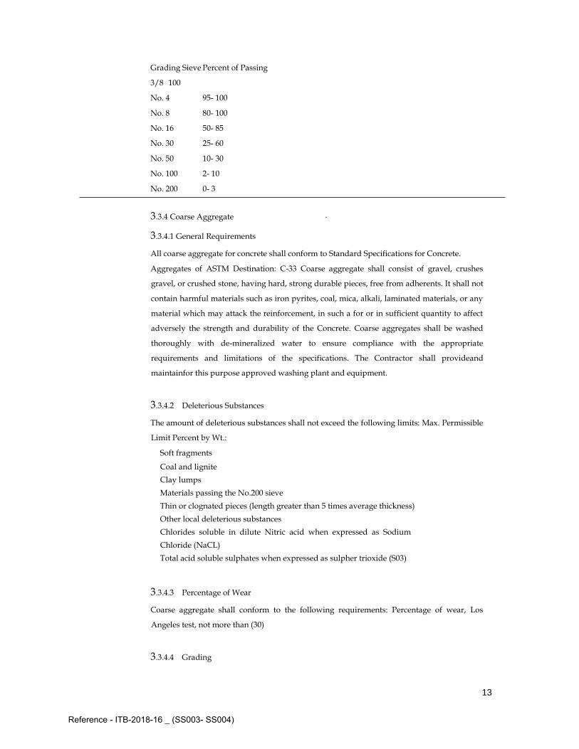
Grading Sieve Percent of Passing
3/8 100
No. 4 95- 100
No. 8 80- 100
No. 16 50- 85
No. 30 25- 60
No. 50 10- 30
No. 100 2- 10
No. 200 0- 3
3.3.4 Coarse Aggregate
3.3.4.1 General Requirements
All coarse aggregate for concrete shall conform to Standard Specifications for Concrete.
Aggregates of ASTM Destination: C-33 Coarse aggregate shall consist of gravel, crushes
gravel, or crushed stone, having hard, strong durable pieces, free from adherents. It shall not
contain harmful materials such as iron pyrites, coal, mica, alkali, laminated materials, or any
material which may attack the reinforcement, in such a for or in sufficient quantity to affect
adversely the strength and durability of the Concrete. Coarse aggregates shall be washed
thoroughly with de-mineralized water to ensure compliance with the appropriate
requirements and limitations of the specifications. The Contractor shall provideand
maintainfor this purpose approved washing plant and equipment.
3.3.4.2 Deleterious Substances
The amount of deleterious substances shall not exceed the following limits: Max. Permissible
Limit Percent by Wt.:
Soft fragments 2
.
0
0
Coal and lignite 0
.
5
0
Clay lumps 0
.
2
5
Materials passing the No.200 sieve 1
.
0
0
Thin or clognated pieces (length greater than 5 times average thickness) 4
.
0
0
Other local deleterious substances 0
.
0
0
Chlorides soluble in dilute Nitric acid when expressed as Sodium 0
.
0
5
Chloride (NaCL)
Total acid soluble sulphates when expressed as sulpher trioxide (S03) 0
.
5
0
3.3.4.3 Percentage of Wear
Coarse aggregate shall conform to the following requirements: Percentage of wear, Los
Angeles test, not more than (30)
3.3.4.4 Grading
Reference - ITB-2018-16 _ (SS003- SS004)

14
Coarse aggregate, when tested according to the requirements of ASTM, shall meet the
following gradation and shall be uniformly graded within the limits stated in Table 2-2 here
below:
Table 2-2: Grading Analysis for Coarse Aggregate
ASTM Percentage by Weight Passing
Grading
(3/4" to No.4)
Grading
(1" to No.4)
Grading
(2" to No.4)
2 ½ inch -- -- 100
2 inch -- -- 95- 100
1 ½ inch -- 100 --
1 inch 100 95- 100 35- 70
¾ inch 95- 100 -- --
½ inch -- 25- 60 10- 30
3/8 inch 20- 55 -- --
No. 4 0- 10 0- 10 0- 5
No. 8 0- 5 0- 5 --
No. 200 0- 1 0- 1 0- 1
3.3.5 Combined Aggregate
Approved fine and coarse aggregate on each batch of concrete shall be combined in
proportions as approved by the Engineer, according to test results giving the required
compressive concrete stress as specified per type of Concrete.
The combined aggregate gradation using the ¾ in. to No. 4 gradation shall be used for
concrete members with reinforcement to close or permit proper placement and consolidation
of the concrete. Change from one gradation to another shall not be made during the progress
of the work unless approved by the Engineer. Such changes are admitted only after being
proved by test results.
3.3.6 Aggregate for Mortar
3.3.6.1 General Requirements
Aggregate for motor shall conform to the Standard Specification for Aggregate for Masonry
Mortar of ASTM Designation: C-144 and shall consist of hard, strong, durable uncoated
mineral or rock particles, free from injurious amounts of organic or other deleterious
substances.
3.3.6.2 Organic Impurities
Fine aggregate for mortar when subjected to the Calorimetric test for organic impurities and
producing a color darker than the standard color shall be rejected.
3.3.7 Water
Reference - ITB-2018-16 _ (SS003- SS004)
15
3.3.7.1 Quality of Water
Water for mixing of concrete shall be fresh, clean and free from injurious amounts of oil, acid,
or any other deleterious mineral and/or organic matter. It shall not contain chlorides such as
sodium chloride in excess of 700 ppm. It shall not contain any impurities in amount sufficient
to cause a change in the time of setting of Portland Cement of more than 10 percent, nor a
reduction in compressive strength of mortar of more than 5 percent compared to results
obtained with distilled water.
The PH of the water for mixing and curing of concrete shall not be less than PH 4.5 or more
than PH 8.5.
3.3.7.2 Tests for Water
When required by the Engineer the quality of the mixing water shall be determined by the
Standard Method of Test for quality of water to be used in concrete, as specified in B.S. 3148:
1959 Tests for Water for Making Concrete.
In sampling water for testing, care shall be taken to ensure the containers are clean and that
samples are representative.
3.3.7.3 Admixtures
Admixtures in concrete shall be used only when approved by the Engineer and shall
conform to the requirements of the ASTM Standard Specifications Designation c-494-68 for
Water Reducing and Retarding Admixtures, and C-260-69 for Air entraining
Admixtures for Concrete, and waterproofing and watertight.
The Contractor shall ensure that the admixture supplied for use in the work is equivalent in
composition to the admixture subjected to test under this Specification. Tests shall be made
whenever practicable using the cement, aggregates, admixtures proposed for specific work,
because the specific effects produced by chemical admixtures may vary with the properties
of the other ingredients of the concrete.
The specific effects produced by chemical admixtures may vary with the properties of the
other ingredients of the concrete.
Admixture that contains relatively large amounts of chloride shall accelerate corrosion of
reinforcing steel and shall be the cause of rejection.
Water reducing and retarding admixtures shall comply with the physical requirements of
ASTM tests and shall be approved in writing by the Engineer.
When the admixture is delivered in packages or containers, the proprietary name of the
admixture, the type and the weight or volume shall be plainly marked thereon. Similar
information shall be provided in the shipping advises accompanying packaged or bulk
shipments of admixtures.
The admixture shall be stored in such a manner as to permit easy access for proper
inspection and identification of each shipment, and in a suitable weather-tight store that will
protect the admixture from dampness.
Costs of such admixtures, sampling and testing shall be at the Contractor’s expense.
Reference - ITB-2018-16 _ (SS003- SS004)

16
3.4 COMPOSITION OF CONCRETE
The cement content, coarse aggregate size, water content, consistency and the approximate
weights of fine and coarse aggregate (saturated surface-dry basis) for the class of concrete
shall be within the requirements of Table 2-3 (I) and Table 2-3 (II) Below.
The weight of fine and coarse aggregate given in Table 2-3 (II) below is based on the use of
aggregates having bulk specific gravities, in a saturated surface-dry condition, 2.65-5%. For
reasonably well graded materials of normal physical characteristics, the use of the below
indicated proportions, together with specified water content to obtain the required
consistency, will result in concrete of the specified cement content, plus or minus two (2)
percent.
For aggregate having specified gravities outside the ranges indicated in the Table 3-3 (II)
below, the weights shall be corrected by multiplying the weights shown in Table 3-3
(II)below by the ration of the specific gravity of the aggregate and 3.65.
The relative weights of fine and coarse aggregate per sack of cement given in Table 3-3 (II)
below are based on the use of natural sand having a fineness modulus within the range of
2.70 and 2.90 and methods of placing which do not involve high frequency vibration. When
sharp, angular manufactured sands, or extremely coarsely graded sands are used, the
relative amount of fine aggregate should be increased. For finer sands the relative amount of
fine aggregate should be decreased. In general, the least amount of sand which will insure
concrete of the required workability for the placing conditions involved should always be
compensated for by changing the weight of coarse aggregate in the opposite direction by a
corresponding amount.
Table 3-3 (I): Requirements of concrete composition
Kind of
Concrete
Cylinder
compressive
strength at
28 days
(kg/ cm2)
Minimum
Cement
Content (Kgs)
Coarse Aggregate Size Max. Water
Content
(Liters Per
Bag)
Maximum Water-
Cement Ratio, By
Weight, Normal Weight
Aggregate concrete
vibrated Vibrate d
B 400 320 350 ¾ “ or 1” – No. 4 as
required by C.M.
25 0.45 50-100
B 300 240 300 Ditto 27 0.50 50-100
B 250 200 275 Ditto 27 0.50 50-100
Reference - ITB-2018-16 _ (SS003- SS004)

17
Table 3-3 (II): Requirements of concrete composition- Continue
Class of
Concrete
Cylinder compressive
strength at
28 days
(kg/ cm2)
Approximate Weight (Saturated Surface-Dry) of Fine and
Coarse Aggregate per Sack
(50Kgs) of Cement
Rounded coarse aggregate Angular coarse aggregate
Fine (Kg) Coarse (Kg) Fine (Kg) Coarse (Kg)
B 400 320 75 150 80 140
B 300 240 85 170 95 150
B 250 200 95 180 100 160
Table 2-3 (II) is given for indicative purposes and is not binding.
The total sodium chloride content of any materials used for making concrete shall be less
than:
For mass concrete.............. 1.5 percent
For reinforced concrete........ 0.7 percent
Expressed as a percentage, by weight of the cement.
In calculations made under the provisions of this clause, any chloride, other than sodium
chloride in the materials shall be converted to the equivalent of sodium chloride and be
added to the amount of sodium chloride. The sulphate content shall not exceed 0.03 percent
by weight of the cement.
3.5 PROPORTIONS
3.5.1 General
After the materials provided by the Contractor have been accepted for the works, the
proportions and equivalent batch weights shall be determined which will produce concrete
having not less than the strength required.
3.5.2 Trial Mixes
The actual proportions shall be determined on the basis trial mixes made by the Contractor
and conducted with the content being determined by means of yield test in accordance with
American Society for Testing Material (ASTM) Designation (C-138). The proportions will be
such as to required (within a tolerance of plus or minus one (1) percent, the cement content
shown in Table I as the minimum cement content, provided, however, that if the materials
supplied by the Contractor are of such a nature or are so graded that proportions based on
the minimum cement content cannot be used without exceeding the maximum allowable
water content specified in Table I, the proportions will be adjusted so as to require the least
amount of cement which will produce concrete of the required plasticity and workability
without exceeding such maximum allowable water content. No additional compensation will
be made for the increase in quantity of cement required.
Reference - ITB-2018-16 _ (SS003- SS004)

18
3.5.3 Contents
The mixes required will be designated in kilograms of fine and coarse aggregate exclusive of
free water, per sack (50 Kilograms) of cement and in liters of total mixing water per sack of
cement on the basis of the required amount of cement per cubic meter of concrete.
3.5.4 Batch Weights
Since the proportions are designated in terms of aggregate in surface-dry condition, the
equivalent batch weights to be used in the work shall be corrected periodically to take into
account the actual moisture content of the aggregates at the time of use.
3.6 CONCRETE COMPRESSION AND SLUMP TESTS
3.6.1 Cubical Test
The Compression Strength of Concrete shall be obtained according to cubical tests locally
done. Test cubes made in the field shall have a dimension of 15cm, At least 3 separate
batches of concrete shall be made for trial and these shall be tested for compliance with the
requirements of the table below, at least 3 test cubes being made from each batch of concrete.
Once a mix is approved no substantial change in the materials or proportions of materials
being used shall be made without the approval of the director of works who may then
require further trial mixes to be produced. The compressive strength of the concrete will be
taken as the arithmetic mean of the strength of all the cubes tested.
The following table 3-4 will be used to compare test results:
Table 3-4: Compressive Strength results of samples of concrete at 28 days. (Mixed by Weight)
Kind of Concrete Mean value At
28 days Kg /
cm2
Minimum Individual
Value at 28 days Kg /
cm2
Mean value At
28 days Kg /
cm2
Minimum
Individual Value at
28 days
Kg / cm2
In case of 3-4 samples taken In case of 5 samples or more
B 150 185 130 175 130
B 200 240 170 230 170
B 250 300 215 290 215
B 300 360 255 345 255
B 350 420 300 405 300
Test at 7 days must not be less than 75% of the required strength at 28 days
3.6.2 Slump Tests
Slump tests shall be carried out periodically to ensure the appropriate water cement ratio in
accordance with the Standard Method of Test of Slump of Portland Cement Concrete of the
ASTM Designation: C-143.
3.6.3 Test of Hardened Concrete in the Structure
Where the results of specimens indicate that the concrete does not meet specification
requirements, core boring tests conforming to the current issue of ASTM Designation: C-42
shall be performed, as directed by the Engineer, all at the Contractor’s expense.
Reference - ITB-2018-16 _ (SS003- SS004)

19
1. Hardened concrete is identical to specifications if the results of specimens test follow the
conditions:
At least the average compressive strength of samples testing coincides the required
design strength for the concrete.
No compressive strength of any of the sample specimens deviates from the required
design strength for the concrete by (85%).
Cubes are standard size (150 × 150 × 150) mm and age (28) days mainly to the
requirements of comparing strength. The nominal compressive strength is the
minimum value of all the values of the testing samples, which does not allow the existence of
values lower than more than (5) percent of the number of sample tests.
The contractor to submit to the supervisor written reports from an authorized
laboratory for all of the tests carried out according to specifications and within period of
not more than (24) hours of the implementation of the testing.
2. If the cube tests fail to pass the above; Core Specimens must be carried out at (3) specimens
for each sample of hardened concrete which had not achieved the conditions of the sub-item
mentioned above. Note that taking the specimens, water treatment and testing are in
accordance with the requirements of American Standard (ASTM -C 42), this is coincided to
the concrete specifications if the test results match following conditions:
At least the average compressive strength of the specimens of a sample is (85%) of the
strength provided by the design.
At least the compressive strength of an individual specimen from a sample is (75%) of
the strength provided by the design.
3. If test results fail to pass the condition stated in item (B) of this section, found not conform
to these specifications, and must then be completely removed from the site at the expense of
the contractor, as the same contractor bears full responsibility for any damage that might be
caused to the sound elements as a result of the demolition and removal.
4. As exception to what is stated in paragraph (C) of this section, for the slabs and beams
only, if the average value of compressive strength of the samples equivalent to the standard
cubes (150 * 150 * 150) mm is not less than (150Kg/cm2); loading test might be carried out
only upon the client request and at the contractor’s expense to ensure the ability of the
concrete elements to bear loads according to engineer and the designer. If the elements pass
the load test, then the slabs and beams are considered structurally accepted.
5. Loading Test
Load test must be carried out at the site for the slabs and beams of reinforced concrete
that are under the age of (56) days by authorized and experienced laboratory in that field.
Reference - ITB-2018-16 _ (SS003- SS004)

20
The loads must be equivalent to that part of the actual dead loads and shall be placed on the
slabs and beams prior to loading the total loads by (48) hours and remain until the end of the
test.
The slabs and beams must be loaded by a total of (0.85) multiplied by (1.4 Dead Load
+ 1.7 Live Load) Less Dead Load actually performing (48) hours before. Special devices
should be placed at the bottom of slabs and beams to measure deflection. These devices
should be installed on fixed frames to ensure the stability of these devices, and the
preliminary readings to be taken prior to process of loading. The loads must be placed
gradually and systematically for (24) hours, without causing any vibrations or shocks and
batches of not less than (4) equal installments, and then taking the readings , which
identifies the maximum deflection; that is the difference between this reading and reading
pre-loading. Then the loads are lifted and left unloaded for two (24) hours, the readings are
taken for the final deflection which determines the value of self-retrieval as the difference
between this reading, and reading pre-lift.
6. Passing the test
The structural elements could succeed in passing the test, if not exceed the maximum
deflection (D) in mm as per the formula:
D = (50 L2) / h
Where:
L = Span loaded in meters of the following values: the distance between the centers of
supports or clear span loaded plus the height of the structural element which is smaller. h =
height of the structural element (mm)
The slabs and beams fail to pass the test if wide cracks appear or signs of failure during
the test, or if they do not achieve the value of deflection (D).
3.7 MEASUREMENT OF MATERIALS
Materials shall be measured by volumetric measurements or any other mothods authorized
by the Engineer for project.
Concrete shall be measured net, no deduction will be made for:-
a) Volume pieces and spaces.
b) Distance pieces and spaces.
c) Rods and bars in any location and at any height.
d) Cutting and waste.
e) Steel reinforcement bars.
f) Ready mix concrete with pump… etc.
Rate for concrete work shall include for:-
a) Vibrating and packing around reinforcement and between form work.
b) Curing and sprinkling.
c) Work of any cross –section area and at any height.
Reference - ITB-2018-16 _ (SS003- SS004)
21
d) Grading, tamping and traveling.
e) Form work and metal ties.
f) Form work grooves, throats, holes, chases rebates chamfer, splayed angles, molding
and the like.
g) Forming mortises and grouting in.
h) Steel reinforcement of any grade, size and length as in detailed drawings. i)
Construction expansion and contraction control joints.
j) The use of white cement where necessary. k) Mastic sealant.
l) Approved additives and admixtures. m) Sampling and testing.
3.8 MIXING OF CONCRETE
2.8.1 General
Unless otherwise authorized by the Engineer, concrete shall be machine mixed.
The mixing of concrete or mortar shall not be permitted when the temperature is above 40 C
or when the temperature is below 5 C.
3.8.2 Mixing on Site
Concrete shall be thoroughly mixed in a batch mixer conforming to the requirements of B.S.
1305 Batch type concrete mixers which will ensure a uniform distribution of the materials
throughout the mass.
The mixer shall be equipped with adequate storage and a device for accurately measuring
and automatically controlling the amount of water used on each batch. Preferably
mechanical means shall be provided for recording the number of revolutions for each batch
and automatically preventing the discharge of the mixer until the materials have been mixed
within the specified minimum time.
The entire contents of the mixer shall be removed from the drum before materials for a
succeeding batch are placed therein.
All concrete shall be mixed for a period of not less than 1 ½ minutes after all materials,
including water, are in the mixer. During the period of the mixing the mixer shall operate at
the speed for which it has been designed, but this speed shall be not less than 14 nor more
than 20 revolutions per minute.
The first batch of concrete material placed in the mixer shall contain sufficient excess of
cement, sand and water to coat the inside of the drum without reducing the required mortar
content of the mix. Upon the cessation of mixing for a considerable period, the mixer shall be
thoroughly cleaned.
3.8.3 Truck Mixing
Truck mixers, unless otherwise authorized by the Engineer, shall be of the revolving drum
type, watertight, and so constructed that the concrete can be mixed to ensure a uniform
distribution of materials throughout the mass. All solid materials for the concrete shall be
Reference - ITB-2018-16 _ (SS003- SS004)

22
accurately measured in accordance with Section C.7 and charged into the drum at the
proportioning plant.
Except as subsequently provided, the truck mixer shall be equipped with a tank for carrying
mixing water. Only the prescribed amount of water shall be placed in the tank unless the
tank id equipped with a device by which the quantity of water added can be readily verified.
Truck Mixers may be required to be provided with means by which the mixing time can be
readily verified by the Engineer.
The maximum size of batch in truck mixers shall not exceed the maximum rated capacity of
the mixer as stated by the manufacturer and stamped in metal on the mixer. Truck mixing
shall be continued for not less than 50 revolutions after all ingredients including the water,
are in the drum. The speed shall not be less than 4 r.p.m., nor more than a speed resulting in
a peripheral velocity of the drum of 70 meters per minute.
Nor more than 100 revolutions of mixing shall be at speed in excess of 6 r.p.m. Mixing shall
begin within 30 minutes after the cement has been added either to the water or aggregate.
When cement is charged into a mixer drum containing water or surface-wet aggregate and
when the temperature is above (33 C) is used this limit shall be reduced to 1245 minutes; the
limitation on time between the introduction of the cement to the aggregates and the
beginning of the mixing may be waived when, in the judgment of the Engineer, the
aggregates are sufficiently free from moisture, so that there will be no harmful effects on the
cement.
3.8.4 Partial mixing at the Central Plant
When a truck mixer provided with adequate mixing blades is used for transpiration, the
mixing time at the mixing plant may be reduced to 30 seconds and the mixing completed in
the truck mixer. The mixing time in the truck mixer shall be as specified under the Section
C.8.3 for truck mixing.
3.8.5 Plant Mix
Mixing at a central plant shall conform to the requirements for mixing at the Site and shall
conform to
the applicable requirements of the Standard Specification for Ready-Mixed Concrete of
ASTM Designation: C-94.
3.8.6 Time of Hauling and Placing Concrete
If the distance from the mixing plant to the construction Site is so great that between the time
of mixing and pouring the concrete, the temperature is below 40 C and the traveling time is
more than 30 minutes, truck mixers must be employed.
When truck mixers are used, concrete shall be discharged and placed in its final position in
the forms within thirty (30) minutes after water is first added to the mix.
3.8.7 Delivery
Reference - ITB-2018-16 _ (SS003- SS004)
23
The rate of delivery of concrete during concreting operations shall be such as to provide for
the proper handling, placing and finishing of the concrete. The rate shall be such that the
interval between batches shall not exceed 20 minutes. The methods of delivering and
handling the concrete shall be such as will facilitate placing with the minimum of re-
handling and without damage to the structure of the concrete.
3.8.8 Re-tempering
The concrete shall be mixed only in such quantities as are required for immediate use and
any concrete which has developed initial setting shall not be used. Concrete which has
partially hardened shall not be re-tempered or remixed.
3.9 HANDLING AND PLACING CONCRETE
3.9.1 General
Prior to pouring concrete in any structure, the Contractor shall secure a written order to
commence from the Engineer. In preparation for the placing of concrete all sawdust, chips,
and other construction debris and extraneous matters shall be removed from the interior of
forms, struts, stays and braces, serving temporarily to hold the forms in correct shape and
alignment, pending the placing of concrete placing has reached an elevation rendering their
service unnecessary. These temporary members shall be entirely removed from the firms and
not buried in the concrete. Concrete shall be placed so as to avoid segregation of the
materials and the displacement of the reinforcement. The use of long troughs, chutes and
pipes for conveying concrete from the mixer to the forms shall not be permitted unless the
authorization in writing of the Engineer is obtained. In case an interior quality of concrete is
produced by the use of such conveyers, the Engineer may order discontinuance of their use
and the substitution of a satisfactory method of placing. Open troughs and chutes shall be of
metal lined and shall be of rounded cross section to avoid the accumulation of concrete in
corners. The chutes shall be equipped with baffles or be in short lengths that reverse the
direction of movement. The slope shall be steep enough (1 vertical to 2 or 2 ½ horizontal) to
permit flow requiring a slump greater than specified or required for placement.
All chutes, troughs and pipes shall be kept clean and free from coating of hardened concrete
by thoroughly flushing with water after each run. Water used for flushing shall be
discharged clear of the structure. When placing operations would involve dropping the
concrete more than 1.50 meter, it shall be deposited through sheet metal or other approved
pipes. As far as practicable, the pipes shall be kept full of concrete during placing and their
lower ends shall be kept buried in the newly placed concrete. After initial setting of concrete,
the forms shall not be jarred and no strain shall be placed on the ends of reinforcement bars
which project.
3.9.2 Hot Weather Concreting
Reference - ITB-2018-16 _ (SS003- SS004)

24
The temperature of concrete when placed shall not exceed 27 °C when the relative humidity
is 50 percent or less and shall not exceed 32 ° C for values of relative humidity between 50
percent and 70 percent, the max temperature of concrete shall be found by interpolation.
In lieu of above, the temperature of concrete when placed shall not exceed 32 ° C, regardless
of the relative humidity.
The Contractor shall comply with the above requirements by the following procedures:-
Cooling the mixing water and/or replacing 50% of the mixing water by crushed ice.
When crushed ice is used it shall be stored at a temperature that will prevent formation of
lumps. The ice shall be completely melted by the time mixing is completed.
Shading aggregate stockpiles and/or keeping moist by sprinkling then with water.
Cement shall not be used if its temperature exceeds 77 °C.
Painting the mixer drum white and spraying it with cool water or shading the mixer
from direct sunrays.
Maintaining the mixing time and delivery time to the minimum acceptable.
Sprinkling of forms sub-grade and reinforcement with cool water prior to placement of
concrete.
Water reducing and retarding admixture shall be used in all concrete work when the
temperature of concrete exceeds 27 ° C. The water cement ratio inclusive of free surface
moisture on aggregates and any admixtures shall be kept to a minimum.
3.9.3 Vibrating Concrete
Concrete, during and immediately after depositing, shall be thoroughly compacted. The
compaction shall be done by mechanical vibration subject to the following provisions:
Vibration shall be internal unless special authorization of other methods is given by the
Engineer or as provided herein.
Vibration shall be of a type and design approved by the Engineer. They shall be capable
of transmitting vibration to the concrete at frequencies of not less than 4500 impulses per
minute.
The intensity of vibration shall be such as to visibly affect mass concrete of 25mm
slump.
Contractor shall provide a sufficient number of the vibrators to properly compact each
batch immediately after it is placed in the forms.
Vibration shall be manipulated so as to thoroughly work the concrete around the
reinforcement and embedded fixtures, and into the corners and angles of the forms.
Vibration shall be applied only by experienced operators under close supervision, at the
point of deposit and in the area of freshly deposited concrete. The vibrators shall be inserted
and withdrawn out of the concrete slowly. The vibration shall be of sufficient duration and
intensity to thoroughly compact the concrete, but shall not be continued so as to cause
segregation. Vibration shall not be continued at any point to the extent that localized areas of
grout are formed.
Reference - ITB-2018-16 _ (SS003- SS004)

25
Application of vibration shall be at points uniformly spaced and not farther apart than
twice the radius over which the vibration is visibly effective.
Vibration shall not be applied directly or through the reinforcement to sections or layers
of concrete which have hardened to the degree that the concrete ceases to be plastic under
vibrations. It shall not be used to make concrete flow in the forms over distances so great as
to cause segregation, and vibrators shall not be used to transport concrete in the forms.
Vibrator shall be supplement by such spading as it necessary to ensure smooth surface
and dense concrete along form surfaces and in corners and locations impossible to reach with
the vibrators.
The use of implements such as compressors which are likely to disturb or disarrange
reinforcement or formwork shall not be permitted.
Concrete shall be placed in horizontal layers not more than 300mm thick as hereinafter
provided. When less than a complete layer is placed in one operation, it shall be terminated
in a vertical bulkhead. Each layer shall be placed and compacted before the preceding batch
has taken initial set to prevent injury to the green concrete and avoid surfaces of separation
between the batches. Each layer shall be compacted so as to avoid the formation of a
construction joint with preceding layer which has taken initial set.
When the placing of concrete is temporarily discontinued, the concrete after be coming firm
enough to retain its form, shall be cleaned of laitance and other objectionable material to a
sufficient depth to expose sound concrete. To avoid visible points as far as possible upon
exposed faces, the top surface of the concrete adjacent to the forms shall be smoothed with a
trowel.
Immediately following an approved discontinuance of placing concrete all accumulations of
mortar splashed upon the reinforcement bars and the surfaces of forms shall be removed.
Dried mortar chips and dust shall not be puddle into the unset concrete. If the accumulations
are not removed prior to the concrete becoming set, care shall be exercised not to injure or
break the concrete steel bond at and near the surface of the concrete while cleaning the
reinforcement bars.
3.9.4 Joints
Expansion joints shall be formed in the positions indicated and to the details shown on the
Drawings or otherwise ordered by the Engineer. The expansion joints shall be filled with
bitumen impregnated fiberboard to its full depth and width. The filling will be permitted to
be used as permanent formwork only for the second casting. Where the fiberboard is
exposed, it shall be cut back for a depth of at least 1cm. from the chamfered edges, filled and
pointed with a resilient liquid poly sulphide polymer sealant. Whenever the placing of the
concrete is discontinued other than at the expansion faces, this discontinuity shall form a
construction joint. Construction joints are to be made only along a horizontal or vertical
plane except that in the case of inclined or curved members they shall be at right angles to
the principal axis. Care shall be taken to prevent offsetting of the joint and to ensure water
Reference - ITB-2018-16 _ (SS003- SS004)

26
tightness. The joints shall in every way satisfy the requirements of the Engineer, and be in
accordance with the Drawings.
Unless otherwise shown on the Drawings, construction joints will not be allowed in the
supported portion slabs, beams and beam like members. At construction joints the laminate
film and porous layer of the already set concrete shall be removed and the surface keyed by
hacking and then wire-brushed and thoroughly cleaned. Immediately before adding the new
concrete, the surface it to be thoroughly wetted and a 1-cm thick coating of a fresh
cement/sand mortar (having the same proportion of cement/sand as concrete in the mix)
applied to the surface. The new concrete is then to be well compacted into the old.
The number of construction joints should be kept as few as possible consistent with
reasonable precautions against shrinkage. Concreting should be carried out continuously up
to construction joints.
Where it is necessary to introduce construction joints, careful consideration should be given
to their exact location, which should be indicated on the drawings.
3.10 PRECAST HOLLOW CONCRETE BLOCKS [HOURDIS] FOR RIBBED SLABS:
2.10.1 Material and Manufacture
Aggregate shall be so sized, graded, proportioned and thoroughly mixed in a batch with
such proportions of cement and clean water as to produce a homogeneous concrete mixture.
However, in no case shall the proportion of cement in the mixture be less than five (5)
standard [each weighing 50 Kgs] per cubic meter of concrete.
Pre-cast hollow concrete blocks (hourdis) for a ribbed slab shall be manufactured in
approved vibrated, machine.
If for any reason the strength requirement is not achieved, cement shall be increased at the
Contractor’s own expense. The blocks shall be cured for twelve (12) consecutive days and
shall be at least twenty-one (21) days old before incorporation in the Works. The blocks shall
be of an approved pattern of withstanding a compressive force applied at the ends of 30
kgs/cm2 based on the gross sectional area of the block obtained without deducting voids.
The blocks shall be hard, sound, durable, sharp, clean with well defined arises, free from
cracks and flaws or other defects and of the dimensions shown on the Structural Drawings.
The blocks shall be obtained from an approved local factory.
3.10.2 Workmanship
Pre-cast hollow concrete blocks (hourdis) shall be laid exactly in a line with the cells on the
long dimensions.
Close edge blocks shall be used at the end; the dimensions of the ribs and size of reinforcing
bards shall be exactly according to the Structural Drawings, In narrow width specially made
half blocks shall be used and full block shall not be used along their length (with the calls
along the long dimensions of the rib.)
The blocks are to be laid on adequate forms. All blocks shall be cleaned and thoroughly
wetted with clean water before the concrete is poured and labourers shall not be allowed to
Reference - ITB-2018-16 _ (SS003- SS004)

27
walk on them. Any block found to be defective or damaged during concreting operations
shall be removed and replaced before pouring the concrete, all at the contractor’s expense.
3.11 FORMWORK
3.11.1 General
The Contractor shall be responsible for the design and stability of the formwork. The
contractor shall submit a full program of work indicating the various phases for the erection
and removal of forms and the manner in which he intends to execute all concrete works.
3.11.2 Material
All forms shall be of wrought lumber and shall be built mortar tight and of sufficient, rigidity
to prevent distortion due to the pressure of the concrete and other loads incident to the
construction operations. Forms shall be constructed and maintained so as to prevent warping
and the opening of joints due to shrinkage of the lumber.
The forms shall be substantial and unyielding and shall be so designed that the finished
concrete will conform to the proper dimensions and contours. The Contractor shall take into
consideration the effect of vibration on the formwork, and shall be responsible for any
damage or default resulting thereof.
3.11.3 Workmanship
Forms shall be inspected by the Engineer prior to installation of reinforcement
The number of spacing of the form struts and braces shall be such that the forms will be
braced rigidly and uniformly lock joints between form sections shall be free from play or
movement.
The shape, strength rigidity, water tightness and surface smoothness of re-used forms shall
be maintained at all times. Any warped or bulged lumber must be resized before being re-
used. Forms which are unsatisfactory in any respect shall not be re-used.
Metal tie rods or anchorages within the forms shall be so constructed as to permit their
removal to a depth of at least 40mm from the face within injury to the concrete. In case
ordinary wire ties are permitted, all wires, upon removal of the forms, shall be cut back at
least 10mm.
From the face of the concrete with chisels or nippers for green concrete, nippers are
necessary. All fittings for metal ties shall be of such design that the cavities produced upon
their removal are the smallest possible.
The cavities shall be filled with non-shrinkage material mortar and the surface left sound,
smooth, even and uniform in colour.
All forms shall be treated with special approved oil and saturated with water immediately
before placing the concrete. For members with exposed faces, the forms shall be treated with
approval material to prevent the adherence of concrete.
Any material which will adhere to or discolour the concrete shall not be used.
The contractor shall provide means for accurately measuring the settlement of the forms
during placement of the concrete and shall make all necessary corrections as directed by the
Reference - ITB-2018-16 _ (SS003- SS004)

28
Engineer way release the contractor of his responsibility for the correctness of these
schedules.
All reinforcement shall be placed strictly in accordance with the drawings and as instructed
in writing by the Engineer. Nothing shall be allowed to interfere with the required
disposition of the reinforcement, and the Contractor shall ensure that all parts of
reinforcement are placed correctly in position and are temporarily fixed where necessary to
prevent displacement before or during the process of tamping and ramming the concrete in
place. The ties, links or stirrups connecting the bars shall be taut so that the bars are properly
braced the inside of their curved part small be in actual contact with the bars, around which
they are intended to fit. Placed correctly in position and are temporarily fixed where
necessary to prevent displacement before or during the process of tamping and ramming
the concrete in place.
The ties, links or stirrups connecting the bars shall be taut so that the bars are properly
braced the inside of their curved part small be in actual contact with the bars, around which
they are intended to fit.
3.11.4 Removal of Form-work
In the determining of the time for removal of forms, consideration shall be given to the
location and character of the structure, the weather and other conditions influencing the
setting of the concrete and the materials used in the mix. In general, the forms of any
positions of the structure shall not be removed until the concrete is strong enough to prevent
injury to the concrete when the forms are removed. Unless otherwise directed by the
Engineer forms shall remain in place for the following specified period of time:
Centering under beams : 21 days
Floor slabs : 21 days
Walls, columns, sides of beams and other vertically formed surfaces : 3 days
Method of form removal likely to cause overstressing of the concrete shall not be used. In
general, the forms shall be removed from the bottom upwards. Forms and their supports
shall not be removed without the written approval of the Engineer. Supports shall be
removed in such a manner as to permit the concrete to uniformly and gradually take the
stresses due to its own weight.
Centers shall be gradually and uniformly lowered in such a manner as to avoid injurious
stresses in any part of the structure.
The Contractor shall include in his prices for any formwork which may have to be left in
position due to the impossibility of removal of same.
3.12 REINFORCEMENT
3.12.1 General
Reference - ITB-2018-16 _ (SS003- SS004)

29
The contractor shall prepare for his own use bar bending schedules from the information
given on the drawings and in these specifications. These schedules shall be submitted to the
Engineer for approval which shall in no way release the contractor of his responsibility for
the correctness of these schedules.
All reinforcement shall be placed strictly in accordance with the drawings and as instructed
in writing by the Engineer. Nothing shall be allowed to interfere with the required
disposition of the reinforcement, and the contractor shall ensure that all parts of
reinforcement are placed correctly in position and are temporarily fixed where necessary to
prevent displacement before or during the process of tamping and ramming the concrete in
place. The ties, links or stirrups connecting the bars shall be taut so that the bars are properly
braced the inside of their curved part small be in actual contact with the bars, around which
they are intended to fit. Placed correctly in position and are temporarily fixed where
necessary to prevent displacement before or during the process of tamping and ramming
the concrete in place.
The ties, links or stirrups connecting the bars shall be taut so that the bars are properly
braced the inside of their curved part small be in actual contact with the bars, around which
they are intended to fit.
3.12.2 Type and Quality of Steel Reinforcement
1. Hot-Rolled Steel Plain Rods and Bars Hot rolled steel plain rods and bars shall conform to
the strength requirements and minimum elongation of the Standard Specification for
Deformed Billet-Steel Bars of Grade 40 with minimum yield strength 2400Kg/cms (35000 psi)
for concrete Reinforcement of ASTM Designation (A-615) or equivalent.
2. Deformed Steel Rod and Bars
Deformed steel and bars shall conform to the requirements of the Standard Specification for
Deformed Billet-Steel Bars of grade 60 with minimum yield strength 4200 kg/cm2 (60000 psi)
for concrete reinforcement of ASTM Designation (A-615) or equivalent.
3.12.3 Wire
Wire for bending reinforcement bars shall be of soft black annealed mild steel wire. The
diameter of the Wire shall not be less that 16 S.W.G. (1.6mm) and the binding shall be twisted
tight with proper pliers. The free ends of the binding wire shall be bent inwards.
3.12.4 Order Lists
Before ordering material, all order lists and bending diagrams detailed in accordance with
the latest revision of AGI Building Code shall be furnished by the contractor for the approval
of the Engineer, and no material shall be ordered until such lists and steel bending diagrams
have been approved. The approval of order lists and bending diagrams by the Engineer shall
in no way relieve the contractor of his responsibility for the correctness of such lists and
diagrams. Any expenses incurred to the revision of material furnished in accordance with
Reference - ITB-2018-16 _ (SS003- SS004)

30
such lists and diagrams to make and comply with the design drawings including cut and
waste shall be borne by the contractor.
3.12.5 Protection of Material
Steel reinforcement shall be protected at all times from injury. When placed in the work, it
shall be free from dirt, detrimental scale, paint, oil, loose, rust, grease or other foreign
substances.
3.12.6 Fabrication
Bar reinforcement shall be bent to the shapes shown on the Drawings and Steel Bending
(Diagrams), bending dimensions and scheduling of bars for the reinforcement of concrete.
All bars shall be bent cold, unless otherwise permitted by the Engineer. No bars
partially embedded in concrete shall be bent except as shown on the plans or specifically
permitted by the Engineer.
3.12.7 Placing and Fastening
All steel reinforcement shall be accurately placed in the position shown on the drawings and
firmly held during the placing and setting of concrete. Bars shall be tied at all intersections
except where spacing 300mm in each direction, in which case alternate intersections shall be
tied.
Distance from the forms shall be maintained by means of stays, blocks ties, hangers, or other
approved supports. Blocks for holding reinforcement from contract with the forms shall be
pre-cast mortar blocks of approved shapes and dimensions or approved metal or plastic
chairs. Metal chairs which are in contact with the exterior surface of the concrete shall be
galvanized. Layers of bars shall be separated by pre-cast mortar blocks or by other equally
suitable devices. The use of pebbles, pieces of broken stone or brick, metal pipe and wooden
blocks shall not be permitted. Reinforcement in any member shall be placed and then
inspected and approved by the Engineer before the placing of concrete begins. Concrete
placed in violation of this provision may be rejected and its removal is required.
3.12.8 Splicing
All reinforcement shall be furnished in the full lengths indicated on the drawings. Splicing
bars, except where shown on the drawing, will not be permitted without the written
approval of the Engineer. Splices shall be staggered as far as possible.
Additional splices, other than those shown on the drawings; and allowed by the Engineer,
shall be at the contractor’s own expense.
The cost of all supports for holding reinforcement bars shall be borne by the Contractor.
3.13 CURING AND PROTECTION
3.13.1 Water Curing
Reference - ITB-2018-16 _ (SS003- SS004)

31
All concrete shall be cured for a period of time required to obtain the full-specified strength
but not less than seven (7) consecutive days. Unformed surfaces shall be covered with sand
burlap, or other approved fabric mats kept continually wet. If the forms are removed before
the end of the curing period, curing shall be continued as on the uniformed surfaces. When
burlap, sand or other approved fabric materials are used, they shall not cause any
undesirable finish such as rough surface and discoloring where exposed to light.
Unhardened concrete shall be protected from heavy rains or flowing mechanical
injury and the Contractor shall submit for the Engineer’s approval his construction
procedure which is designed to avoid such an eventually. No fire or excessive heat shall be
permitted near or in direct contact with concrete at any time. Water for curing shall conform
to Section 3.3.6.
3.13.2 Curing with Curing Media
Curing medium shall meet all requirements of the specifications for Liquid Membrane-
Forming Compounds for Curing Concrete of ASTM Designation: C-309 and test for water
retention by concrete curing materials of ASTM Designation: C-156.
The compound shall be applied to the concrete surface by means of a sprayer, roller or
lamb’s wool applicator and shall be sprayed on. Ample time shall be allowed for the concrete
surface to harden and to prevent any damage. The compound shall give a drying time not to
exceed thirty minutes, and shall be applied undiluted directly from the manufacturer’s
labeled container in accordance with the manufacturer’s directions and to the satisfaction of
the Engineer.
The compound shall be completely compatible with adhesives, joint sealants and cement
grout.
3.13.3 Payment
No separate payment shall be made for curing with water or with curing media. The cost of
such curing shall be deemed to be included in the Unit Prices of “CONCRETE WORK”.
3.14 CONCRETE [FAIR FACE] EXPOSED SURFACES
3.14.1 Formwork
Formwork for exposed concrete surface shall conform to the applicable requirements of
Section C 14, in addition to those Specifications.
All concrete surfaces that are to be left exposed to view as a finished surface except for pre-
cast concrete units, shall be produced by vertical metal shuttering.
The quantity of the surface of concrete exposed to view shall be consistent throughout the
project and the following methods shall be adopted to obtain the required finish.
Metal forms of an approved type for pre-cast units.
Reference - ITB-2018-16 _ (SS003- SS004)

32
The Contractor may submit alternative proposals for the Engineer’s approval if he so desires.
The Contractor is to submit to the Engineer for his approval shuttering details and sequence
of operation relating to fair face concrete work. Sample panels shall be constructed for all
their face concrete finishes and following the Engineer’s approval the panels will remain on
site and constitute a standard which must be maintained throughout the duration of the
Contract.
3.14.2 Coating Forms with Mineral Oil
In addition to the above forms or linings, the forms shall be coated before placing
reinforcement with an approved colorless mineral oil free of kerosene.
All surplus oil on form surfaces and any oil on reinforcing steel shall be removed.
3.14.3 Samples and Workmanship
The Contractor shall submit for approval a sample panel not less than 600x1200mm to
demonstrate the quantity of the exposed concrete produced by forms at his own expense.
The quantity of the finished work shall be measured against the quality of the approved
sample panel and the work of inferior quality shall be repaired or replaced as directed by the
Engineer without any additional cost.
The quality of the finished surfaces shall be uniform in colour and consistency, whether in
colour or in texture, in any of the finished surfaces, the Engineer may order the repair or the
demolition of the portion of concrete work and the reconstruction of same at the expense of
the contractor and the contractor shall have no right to claim for any expenses or time delay
incurred.
Alternatively the Engineer may order the contractor to plaster all exposed surfaces and bush-
hammer the entire area of, concrete in the project so as to render all exposed surfaces of
concrete consistent throughout the project at the contractor’s own expense.
3.15 MONOLITHIC SMOOTH FINISH SURFACES
All concrete surfaces which are not in acceptance condition and which are required to be
surface-finished as designated herein, shall be rubbed to a smooth and uniform texture with
a carborundum brick and clear water as soon as the forms are removed and the concrete is
ready to hone. The loose material formed on the surface shall be removed as soon as it dries
by rubbing the surface with burlap or other approval material. A cement wash shall not be
used. Concrete surface shall be free from honeycombing, air holes, fins and projections
arising from defective mixings, placing or formwork. When the formwork has been stuck off,
the surface of concrete shall be left untouched until inspected by the Engineer. Any defective
concrete work shall at the discretion of the Engineer be demolished completely and rebuilt or
cut out and made good with concrete of the same proportions as the original. Such
rectifications shall be to the satisfaction of the Engineer and at the Contractor’s own expense.
Reference - ITB-2018-16 _ (SS003- SS004)

33
SECTION 4
Fluid Applied Waterproofing
1. GENERAL
1.1 WORK INCLUDED
a. Cleaning and preparing surfaces to receive waterproofing.
b. Supply and application of fluid applied waterproofing.
1.2 RELATED WORK
a. Rigid Insulation
b. Mechanical items projecting through membrane waterproofing.
1.3 REFERENCE STANDARDS
a. ASTM C355 - Water Vapor Transmission of Thick materials,
b. ASTM D412 - Rubber Properties in Tension.
c. ASTM D624 - Rubber Property - Tear Resistance.
d. ASTM D2240- Rubber Property - Durometer Hardness
1.4 PRODUCT DATA
The Trade Contractor shall submit the following:
a. Product data.
b. Manufacturer’s recommendations for surface conditioner compatibility, elastic
flashing, joint cover sheet and joint and crack sealant along with temperature
range for application of waterproofing membrane for review by the Design
Professional.
c. Method statement for undertaking the work for the review and approval of the
Design Professional.
1.5 ENVIRONMENTAL REQUIREMENTS
a. Fluid waterproofing shall not be applied during inclement weather or when air
temperature is below 40 degrees F (5 degrees C).
b. Fluid waterproofing shall not be applied to damp, frozen, dirty, dusty, or
unsuitable deck surfaces. Concrete surfaces must be cured for 28 days prior to
receipt of any liquid applied waterproofing.
c. Adequate ventilation shall be provided when waterproofing membrane is
applied in enclosed areas, to remove toxic fumes.
1.6 WARRANTY
Reference - ITB-2018-16 _ (SS003- SS004)

34
a. The Trade Contractor shall provide written warranties in the name of the
Owner for the liquid applied waterproofing material.
b. The warranty shall provide for making good, within period of five (5) years, at
no cost to
Owner, failures of waterproofing to resist penetration of water, except where
such failures
are result of structural failures of building. Hairline cracking due to
temperature or shrinkage is not considered as structural failure.
1.7 INSPECTION AND TESTING
The Trade Contractor shall observe/comply as follows:
a. Inspection and when necessary, testing will be performed by a qualified &
approved firm.
b. Perform inspection of membrane waterproofing to ensure conformance with
requirements. If defects are revealed, the Design Professional may request that
waterproof membrane be subject to tests to ascertain full extent of defects. Pay
for costs of required testing and inspection.
c. Correct defects and irregularities as advised by the Design Professional pay for
costs incurred including additional inspection and testing of corrected work.
2. PRODUCTS
2.1 ACCEPTABLE MANUFACTURERS
The Trade Contractor shall submit to the Design Professional the names of three
manufacturers and their products which will be acceptable under this Section. Approval
of the manufacturer or product must be obtained before proceeding with associated
work.
2.2 MATERIALS
a. Waterproofing Membrane: Two component elastomeric compound; cold
applied; quick setting.
b. Cured Membrane Characteristics:
PROPERTIES TEST METHOD Tensile Strength ASTM D 412 Elongation (Ultimate)
ASTM D 412
Hardness ASTM D 2240
Tear Strength ASTM D 624
Water Absorption (22 degrees C) 7 days @ 72 degrees F
Water Vapor Perm Adhesive ASTM C 355
c. Surface Conditioner: Type compatible with membrane compound; as
recommended by fluid membrane manufacturer.
d. Elastic Flashings: 1.19 mm thick butyl or neoprene as recommended by the
waterproofing membrane manufacturer.
Reference - ITB-2018-16 _ (SS003- SS004)

35
e. Joint Cover Sheet: Elastic sheet material designed for and compatible with the
membrane waterproofing.
f. Joint and Crack Sealant: as recommended by waterproofing membrane
manufacturer.
g. Back up Material: PVC membrane or butyl rod or other suitable support
material.
h. Tack-free Surfacer: Normal Portland cement or stone dust.
I. Protection Board: 12mm thick asphalt impregnated board.
3. EXECUTION
3.1 INSPECTION OF SURFACES AND CLEANING
The Trade Contractor shall observe/comply as follows:
a. Ensure that drains, sleeves and curbs which pass through surfaces to receive
waterproofing are properly and rigidly installed.
b. Ensure surfaces are free of cracks, depressions, waves or projections which may
be determintal to proper installation of waterproofing membrane. Repair
surfaces as required.
c. Seal cracks and expansion joints with recommended backup material and
sealant. Ensure proper depth width ratio as recommended by sealant
manufacturer,
d. Ensure expansion joints are sharply formed, free of broken edges or loose
aggregates.
e. Clean surfaces of dust, dirt and other foreign matter determintal to proper
installation of waterproofing membrane.
3.2 PREPARATION
Subject to approval of the Design Professional, the Trade Contractor shall perform as follows:
a. Apply surface conditioner at a rate not exceeding 1 liter per 10 square meters
nor less than 1 liter per 5 square meters depending on concrete surface. Protect
surface conditioner from rain or frost until dry.
b. Apply 300mm wide strip of joint cover sheet over cracks, non working joints,
and expansion joints, over 1.6mm but not exceeding 12.7 mm in width.
c. At expansion joints from 12.7 mm to 25 mm in width,.loop cover sheet down
into joint between 1-1/4 and 1-3/4 inch 31.4 and 44.1 mm. Sheet is to extend at
least 6 inches 152 mm on either side of the expansion joint.
d. Center cover sheet over crack or joints. Roll sheet into 3.2 mm coating of waterproofing membrane. Apply second coat over sheet extending minimum of 152mm, beyond sheet edges.
e. Procedure stated above shall also apply to expansion joints between horizontal
and vertical surfaces.
Reference - ITB-2018-16 _ (SS003- SS004)
36
3.3 APPLICATION
The Trade Contractor shall supply materials and perform as follows:
a. Apply waterproofing membrane in accordance with manufacturer’s
recommendations.
b. Temperature of hot poured waterproof membrane is to be within minimum and
maximum range recommended by membrane product manufacturer.
c. Apply and spread membrane to a minimum 3.2 mm thickness and averaging
4.8mm thickness.
d. Continue membrane up vertical surfaces to a minimum of 152 mm unless
otherwise noted.
e. Seal items projecting through membrane.
f. Install membrane flashings and seal into membrane.
g. Reinforce membrane over joints, whether they be static or moving.
h. Immediately after cooling, dust membrane with Portland Cement at rate of
approximately 65 kilograms per 10 square meters.
Reference - ITB-2018-16 _ (SS003- SS004)
37
SECTION 5
Stone Work
1. Scope: This section describes and specifies all work
related to stone building and stone rehabilitation.
2. Standards: applicable provisions of the following standard
Publications shall apply throughout the work :
a. Palestinian General Specifications.
b. Jordanian Technical Specifications.
c. Bs 882 Aggregate for Mortar.
d. Bs 12 – Portland cement.
3. Products:
3.1. Stone Materials and Fabrication:
- All stone materials used in this project shall be first class of local stone (Class
A).
- All stone shall be even grained, free from cracks, seems, holes, shakes,
objectionable irregularities of color, impurities, structural weakness and
other defects.
- All stone shall be obtained from quarries having adequate capacity and facility
to meet the specified requirements. Cutting and finishing shall be
performed by using approved equipment to process the material promptly
on order and in strict accordance with specifications. The contractor shall
provide evidence to this effect.
- Stone rejected for non-compliance with the submitted samples or the
requirements of the specification shall be replaced with material acceptable
to the engineer Replacement shall be prompt and at the contractor’s own
expense. Inspection of stone by the engineer shall not relieve the
contractor of his responsibilities to perform all work in accordance with the
contract documents.
- All stones shall be selected well in advance of the time required.
- Samples of stone materials shall be submitted for the engineer’s approval 30
days before delivery of any such materials to site.
3.2. Stone Classification :
The stone materials shall be class A according to the Jordanian Technical
specifications and shall have to obtain the following Physical and mechanical
properties: -
3.2.1. Absorption:
The percentage of absorption shall not exceed 3 % according to ASTM – C97.
Reference - ITB-2018-16 _ (SS003- SS004)

38
3.2.2. Specific Gravity:
Minimum specific Gravity of stone shall be 2.56 according to ASTM- C97.
3.2.3. Modulus of Rupture:
Shall not be less than 6.9 N/mm2 according to ASTM-C99.
3.2.4. Abrasion Resistance:
For all stone type shall not be less than 10% according to ASTM- C241.
3.3 Stone Finishes:
- The finish of stone shall be according to Architectural drawings and the
descriptions in bill of quantities. Two Samples of stone finishes shall be
delivered to engineer; one of the approved samples is to be submitted to the
stone cutting factory for preparing the order, the other shall be kept with
engineer as a reference.
- The price of finishing stone is deemed to be loaded on the stone item in the
bill of quantities without any allowances for the contractor.
3.4. Stone Fabrication:
1. Fabrication of stone shall be in strict accordance with approved shop
drawings for fabrication, and with specification.
2. All work shall be of the highest quality in accordance with the best trade
practices, and performed by skilled workmen. All materials and workmanship
shall conform to the highest industry standards, including the Jordanian
Technical Specifications.
3. Use no materials, equipment, and or practices that may adversely affect the
functioning, appearance, or durability of the stonework
3.5.Dimensions:
1. All stonework shall be cut accurately to shape and dimensions shown on the
final approved shop drawings. Exposed plane surface shall be true. Bed and
joint surface shall be dressed straight and right angles, to the face, unless
otherwise shown. Patching of stone will not be permitted.
2. The stonework shall include all necessary cutting for anchors, Support plate’s
shelf angles, and dowels, etc.
3.6. Submittals:
Reference - ITB-2018-16 _ (SS003- SS004)

39
3.6.1.General:
Shop Drawings, product Data, and samples, for submittal provision and
procedures.
3.6.2.Shop Drawings and product data:
1. Submit shop drawings and product, shop drawings shall clearly indicate
construction joints, dimensions, and locations.
2. Indicate of pertinent dimensioning, layout construction details, and
method of installation and adjacent construction.
3. Indicate all units of stone, i.e. sills, lintels coping, etc.
4. Submit stone field erection drawings.
5. Submit manufacturer's instructions for use of pointing color and
admixtures.
3.6.4.Samples.
1. Submit two sets of stone, full size units as selected by the engineer to the
project site, in sufficient number to indicate the full range of color, texture
and finish. One of each of the duplicate samples approved by the
engineer will be retained by him at the project site, the other being
returned to the stone supplier for his guidance. Color and type of the
stone- dressing are as mentioned above.
2. The following physical data on proposed stone shall be submitted by the
supplier:
a. Analysis of mineral composition
b. Analysis of chemical composition.
c. Thermal sufficient of expansion.
d. Absorption.
e. Specific Gravity.
f. Modulus of Rupture
g. Abrasion Resistance.
3. Samples of other materials specified here in shall be submitted upon
request by the engineer.
3.7. References:
National Standards referenced her in are included establishing recognized
quality only. Equivalent quality and testing standards will be acceptable subject
to their timely submission, review and acceptance by the engineer.
3.8. Qualification:
Supplier / Fabricator a firm having an adequate supply of specified type of
stone and annual rated production capacity to deliver the stone to the project
Reference - ITB-2018-16 _ (SS003- SS004)

40
site on schedule within a time limit established by the engineer as required to
insure no delay in the progress and completion of the work.
3.9. Delivery, Storage and handling:
a. Packing and loading: finished stone shall be carefully packed and loaded
for Shipment using all reasonable and customary precautions against
damage in transits. No material, which may cause staining, or discoloration
shall be used for blocking or packing.
b. Site storage. The stone shall be stacked on timber or plat forms at least
100 mm above the ground, and extreme care shall be taken to prevent
staining during storage. If storages is to be for a prolonged period,
polyethylene or other suitable plastic film shall be placed between any
wood and finished surfaces, and shall be used also as an overall protective
covering. Salt shall not be used for melting of ice formed on places, or for
any purpose involving its contact with the stone.
c. Any piece of stone showing flaws, cracks, or imperfections such as vents,
sand, and clay holes, Shelly bars, shakes mottle, seams or starts upon
receipt at the storage yard, or at the project sits, shall be discarded and
removed from the work site, and at the contractor’s own expense.
3.10.1. Mortar:
- All materials for mortar shall comply with the Jordanian Technical
specification latest edition ((under stone works)).
- Cement. Cement for setting mortar: non-staining Portland cement. Cement
for pointing Mortar: non-staining white Portland cement.
- Water: water shall be potable, clean and fresh, from public water system.
- Fine aggregate: Well-graded non-staining fine aggregate use white silica
sand for pointing mortar. No other sand shall be permitted for mortar or grout
unless otherwise tested and approved by the Engineer.
- Lime Approved brand of plastic hydrated such
as New England 4X. Mortar Plasticizer.
- In case of necessity use Plasticizer is conforming to BS-4887, or CEBEX
112 or approved equal.
3.10.2. Mortar Mixture:
a. Portland Cement 1 part .
b. Hydrated lime 0-0.25 part .
c. Fine aggregate 3 parts.
d. Plasticizer.
Reference - ITB-2018-16 _ (SS003- SS004)

41
3.10.3. Pointing Mortar:
a. White Portland cement 1part.
b. Sand. 1- 1/2 parts.
c. Add color additive to acquire the color of mortar approved by the Engineer.
3.11. Setting of stone:
A- All setting shall -be done in accordance with the approved shop drawings. All
work shall be set in a rigid and substantial manner, straight and plumb, with
all horizontal lines level and all vertical lines plumb, unless otherwise shown
on the Drawings. Similar abutting profiles shall accurately intersect and be in
true alignment. All joints shall be uniform and shall be of the size and detail
shown on the approved Shop Drawings.
B- All exterior stone joints shall be 5mm wide unless otherwise indicated. Refer
to the approved Shop Drawings for stone joint dimensions.
C- As setting progresses, the work shall be fastened securely to take care of all
dead loads, wind loads and forces, and erection stresses. All units of stones
shall have suitable temporary braces, shores, and stays to hold them in
position until permanently secured.
D- Cavities behind facing stones shall be filled with fine and /or course grout, as
specifically shown on the approved shop drawings and as specified herein.
Permanently secured.
E- Stone elements indicated to be set with mortar joints should be set with two
cushions per stone in every horizontal joint. Stone shall be set in full
horizontal mortar beds and joints raked out to a depth of 19 mm before mortar
has set. The face surfaces shall not be smeared with the mortar forced out of
joints or that used in pointing. No hammering. Rolling or turning of stones will
be allowed on the wall. Precautions shall be taken to prevent seepage of
moisture, through or from the beds and joints, which may cause discoloration
of the exposed surfaces.
F- Allow stone units to set overnight and then completely fill joints with pointing
mortar. Joints shall be tooled flush. During the tooling of the joints, enlarge
any voids or holes and completely fill with mortar. Surfaces of stone shall be
cleaned using sponge and water to remove mortar spills from face of stone.
G- The setting of patched, chipped, cracked, broken, stained or defective stones
shall not be permitted.
H- For any further detailed information, refer to the Jordanian Technical
Specifications latest edition, Section Stone works.
3.12. Stone Repairing:
Reference - ITB-2018-16 _ (SS003- SS004)
42
3.12.1. Repair and replacement of stone:
A- Stones to be repaired or replaced are shown on the drawings or any others
stones requested by the Engineer. Stone should be replaced with stones of similar
material. Color, shape and size, dressing texture free from any defects. Mortar and
pointing shall be as specified, of lime ingredients.
B- Old stones should be removed carefully without affecting the adjacent
stones.
C- Height of joints should be same as adjacent.
D- The traditional construction methods and materials will be used when
replacing stones or rebuilding them.
3.12.2. Grouting
a) The objective is to strengthen decayed masonry, which is weakened by large
fractures and voids.
b) Grout mixtures:-
• 2 part of PFA (pulverized fly ashes in a puzzolanic material.
• Parts lime in volume.
• Parts of bentonite clay additive.
Crushed conical stones should be used to fill wide cracks with mortar solid to
water ratio 1:3.
c) Before inserting the grout close the cracks and the joints in the vaults and
clean voids and wet all surfaces.
d) Grout is inserted working sideways then upwards.
e) Measurement for grouting will be in M2.
3.12.3. New stone:
Recommended use of reused old stones Rates for stone work shall include for:
a) Preparation of any surface.
b) Any width pattern or area, any location and any height.
c) Fair, rebated, rounded, chamfered splayed, beveled, and mould edges grooves
flutes and the like.
d) Square, raking and circular cutting.
e) Cutting and fitting into any opening or recessed area, and fitting around any
section.
f) Admixtures.
g) Traditional stone links over any opening.
h) All reinforced concrete columns inside walls, corners, etc.
i) Fixing any stone (Lintels).
j) Fixing any stone wall at existing building at joints between old and new
elements.
Reference - ITB-2018-16 _ (SS003- SS004)

43
k) Sleeves inside any wall for electrical or sanitary and heating installation and size
is according to the instructions of the architect.
l) Sample of stone should be submitted and approved before commencement of
work. It is recommended to reuse old stones.
m) Size of stone should match existing stone courses.
• Measurement of all types of new stone shall be in meter square no
measurement will be made for any recesses, projections or side of stone
pieces side of jambs and lintels all opening over 0.1 m2 shall be deducted.
• Measurement of coping and sills shall be in square meter.
• Measurement for replacement of decayed stone shall be in square meter or
lump sum as indicated in the bill of quantity.
• Size of stone must be identical to existing, with the same Construction
methods and materials.
3.12.4 Cleaning Masonry
In all cleaning operations the original surface of the stone must be respected,
together with its patina. Wire brushes of any sort should not be used as they may
damage the patina. Cleaning by hand using Nylon brushes only. Before cleaning
test areas must be prepared, in order to agree on the amount of required cleaning
and to find the most suitable method.
a) Weed Removal:-
The recommended treatment for masonry covered with algae, lichen,
mosses and a small plant is described below. The biocides based on a
quaternary ammonium compound effect the initial kill, and when combined
with tributyl tin oxide will have a ling term inhibiting effect on re-colonization.
When handling and mixing biocides, remember to wear rubber gloves and in
addition, when spraying, to wear safety glasses, mask and goggles. Do not
spray in the immediate vicinity of other unprotected people and animals.
1. Remove as much growth as possible in the form of plants and thick
cushions of moss with knife blades, spatulae and stiff bristle or nonferrous
soft wire brushes. If the surface below the growth is delicate or liable to be
marked or scoured in any way this preparation must be limited to lifting of
the moss only.
2. Prepare a solution of quaternary ammonium based biocide to the
manufacturers specification.
3. Fill a pneumatic garden type sprayer two thirds full with the diluted
biocide. Adjust the nozzle to a coarse spray setting. There should be
sufficient pressure at the wand nozzle, after pumping the container to
saturate the surface of the masonry without causing excessive bounce
back and spray drift.
4. Apply a flood coat. Commence at the top of the vertical surface to be
treated and move across horizontally and slowly approximately 100mm
Reference - ITB-2018-16 _ (SS003- SS004)

44
run down. The next horizontal pass should be made across the previous
run down.
5. Leave the treated area for at least one week. Brush off as much dead
growth as hoppers are kept clear.
6. Prepare a solution of a proprietary biocide based on a quaternary
ammonium compound and incorporating tributyle tin oxide or other proven
long lasting biocide to the manufacturers specification.
7. Fill a second pneumatic sprayer with the dilute biocide and apply in eh
same manner as (4) above.
8. Allow the surface to absorb and carry out a second application of
proprietary biocide as (6) above.
b) Mist cleaning:-
Mist cleaning is used for exterior evaluations.
1. Fine mist gives most wetting effect and uses the least amount of water.
2. Should not be done in winter.
3. To obtain a fine mist sufficient water pressure is necessary.
4. The time to soften the dirt must be found by trial and error, once softened
it may be removed by brushing.
5. Wire brushes of any sort should not be used as they may damage the
patina. Use nylon brushes only.
6. Water should be free from any chemicals.
7. No sand blasting is allowed.
c) Paint removal:-
1. Paint should not be removed by abrasives but by solvents, if the surface
of the stone is not to be damaged. Sodium Hydroxide (caustic soda) or
Methyline Chloride are usual.
2. Take care not to spill on adjoining surfaces.
3. The surface of the stone should be thoroughly wetted before applying
chemicals.
4. For sensitive, valuable stonework use poultices of clay or lime or Carboxy
Methyl Cellulose + solvent (Na or Hydroxide).
5. Scrape off with wooden scraper.
6. Rinse off with low-pressure water lance.
7. Neutralize hydroxide with weak (acetic) acid.
d) Rates:-
The rates for cleaning the stone shall include:-
Reference - ITB-2018-16 _ (SS003- SS004)
45
1. Supplying, storing of solvents and other chemicals for cleaning the stone
and removal of paint.
2. Fixing of any damage that might occur during the work of cleaning the
stone.
3. Labor costs of cleaning and paint removal.
4. Cost of materials and tools.
5. Scaffolding costs.
6. Cleaning of surrounding after work.
e) Measurement for stone cleaning are given in square meters. All openings over
0.5m2 shall be deducted.
3.12.05. The Re-pointing Process
a) Preparing the joint:-
Loose, powdery, excessively soft, badly stained or cracked mortar should be
raked (cut out) to a minimum depth (2-2.5 times the width of the vertical joint)
using hand tools, without widening the original joints.
Before filling any brick or stone that are loose should be reset. No electrical
tools to be used.
The joints should be finally cleaned out gently flushing with water to remove all
loose particles and dust.
When filling, the joints should be damp to prevent too rapid absorption of
water form the new mortar, but no standing water should present.
b) The new mortar should:-
1. Match the original mortar in color and texture.
2. Be softer than the brick or the stone and as soft as the original
mortar.
c) Mortar mixes:-
1. The mixes lime / sand (in different proportions) are the traditional mortars,
mixes with lime / sand and set- additive like brick dust is laso required.
2. In time the color and texture of the sand dominate.
3. A clean well graded aggregate is essential for the good performance of
mortars and plasters. Small size aggregates fits between the larger. In
term of size “well – graded” aggregate will range between 2-3, 6mm to
150 microns. The proportions can be determined by a stack of standard
sieves.
4. The use of stone dust is not permitted, a sharp crystalline sand with a little
sparkle is desirable:-
Reference - ITB-2018-16 _ (SS003- SS004)

46
5. St. Astier Limes or similar NHL 2 is recommended 1 volume of NHL 2:2
volumes of sand.
• The fines must be sieved out to avoid putty like surface of the
pointing.
• With some stones the remaining coarse particles may decompose in
time and thus spoil the mortar.
• A proper mix is a proportion of 1:3 wet lime to aggregate (sharp sand
well washed and graded).
d) Filling the joints.
1. The joint should be filled in successive layers, allowing each layer to
harden before adding the following. Layering reduces shrinkage.
2. To give the joint a smooth, denser outer layer the joint must be tooled.
3. It is important to tool at the right moment, when mortar is neither too soft
(hairline cracks may occur), nor too hard.
e) Shaping the joints.
1. pointing styles used on the masonry should be analyzed and reproduced.
2. The appropriate shape of the joint depends on the type of a masonry.
3. The mortar joints should shed water to avoid the penetration and the
accumulation of rainwater between the mortar and masonry elements.
4. The profile to be used is the concave joints.
5. Pointing style must be compatible with the existing pointing styles.
f) Cleaning and aging the mortar.
1. Bits of mortar are best removed with a stiff dry of lightly dampened brush
after the mortar has initially set.
2. If the mortars have been properly matched, it is best to let the new age
staining is an unreliable and unstable technique.
g) Rate should include cost of labor, cost of materials, tools and scaffolding,
cleaning and patching.
h) Measurement for pointing should be in square meters, all opening over
0.5m2 shall be deducted.
Reference - ITB-2018-16 _ (SS003- SS004)
47
SECTION 6
Floor Tile Work
GENERAL
Section Includes: a. Porcelain, Ceramic, and Terrazzo tile floor finish using the mortar bed
application method.
b. Local marble tile stair treads using the mortar bed application method.
References: ANSI
TCA
ASTM
Submittals: a. Shop drawings indicate tile layout, patterns, color arrangement, perimeter
conditions, and junctions with dissimilar materials, control and expansion
joints, thresholds and setting details.
b. Product data: provide instructions for using adhesives and grouts.
c. Samples: Mount tile and apply grout on two plywood panels, (1000X1000) mm.
in size illustrating pattern, color variations, and grouts joint size variations.
d. Manufacturer’s certificate: Certify that products specification meet or exceed
specified requirements.
Maintenance Data a.Maintenance data: Include recommended cleaning methods, cleaning materials, stain
removal methods and polishes and waxes.
Qualification: a. Manufacturer: Company specializing in manufacturing the products specified
in this section with minimum 3 years experience.
b. Installer: Specialist in performing the work of this section with minimum 10
years experience.
Mockup: a. Construct tile mockup, 2m long by 2m wide, with cleavage membrane,
waterproofing, finish grout, and specified accessories.
b. Local where directed.
c. Mockup may remain as part of the work.
Pre-Installation Conference: Convene one week prior to commencing work of this section.
Delivery, storage, and handling a. Deliver storage, and handling to site under provisions of ASTM.
b. Protect adhesives from freezing or overheating in accordance with
manufacturer instructions.
1-9 Environmental requirements: a. Do not install adhesives in an unventilated environment.
b. Maintain 10 degrees C during installation of mortar materials.
Reference - ITB-2018-16 _ (SS003- SS004)

48
PRODUCTS
2-1 Porcelain Tile Materials a. Porcelain Floor Tile:
1. Moisture Absorption 0.5-3 Percent
2. Size As Indicated in BOQ
3. Shape Square
4. Edge Square
5. Surface Finish Matte glazed
6. Color as selected
7. Compressive Strength >
b. Terrazzo Tile:
1. Moisture Absorption 0.5-3 Percent
2. Size As Indicated in BOQ
3. Shape Square
4. Edge Square
5. Surface Finish unglazed
6. Color as selected
c. Local Marble:
1. Moisture Absorption 0.5-3 Percent
2. Size As Indicated in BOQ
3. Shape Rectangular
4. Edge Square
5. Surface Finish Glazed
6. Color as Selected
2-2 Mortar
Materials Portland cement
Sand
Water
3-2 Grout Materials: White Cement
Aggregate
Water
Color
EXECUTION
3-1
Examination: Verify that surfaces are ready to receive work.
3-2 Preparation a. Protect surrounding work from damage or disfiguration.
b. Vacuum clean surfaces.
c. Seal substrate surface cracks with filler.
d. Apply sealer conditioner to substrate surfaces in accordance with adhesive
manufacturer’s instructions.
3-3 Installation – Mortar bed Method:
Reference - ITB-2018-16 _ (SS003- SS004)
49
a. Install mortar bed, tile threshold, stair treads, and grout in accordance with
manufacturer’s instructions.
b. Install cleavage membrane, lap and seal watertight, edges and ends.
c. Apply mortar bed over concrete surfaces to thickness of (30) mm.
d. Lay tile to pattern indicated do not interrupt tile pattern through openings.
e. Place thresholds, edge strips at exposed tile edge.
f. Cut and fit tile tight to penetrations through tile, insure finish trim will cover
cut tile edges. From corners neatly.
g. Place tile joints uniform in width, subject to variance intolerance allowed in tile
size make joints watertight, with out voids, cracks excess mortar or excess
grout.
h. Sound tile after setting, replace hollow sounding units.
i. Allow tile to set for minimum of 48 hours prior to grouting.
j. Grout tile joints.
k. Apply sealant to junction of tile and dissimilar materials and junction of
dissimilar planes.
3-4 Cleaning Clean tile and grout surfaces.
3-5 Protections of finished work Do not permit traffic over finished floor surface for 4 days after installation.
Reference - ITB-2018-16 _ (SS003- SS004)

50
SECTION 7
Wall Tile Work
1- GENERAL
1-1 SECTION INCLUDES
Ceramic tile wall finish using the mortar bed application method.
1-2 REFERENCES
a. ANSI A108.1 – Installation of ceramic tile with Portland cement mortar.
b. ANSI A 108.1 – Installation of Grout in tile work.
c. ANSI A 118.6 – Ceramic tile Grouts.
d. ANSI A 137.1 – Standard Specifications for ceramic tile.
e. TCA – Handbook for ceramic tile Installation.
1-3 SUBMITTALS
a. Shop drawings: Indicate tile layout, patterns, color arrangement, perimeter conditions,
junctions with dissimilar materials, control and expansion joints, threshold and setting
details.
b. Product data: provide instructions for using adhesives and grouts.
c. Samples: mount tile and apply grout on two-plywood panels (500x500) mm size
illustrating pattern, color variations, and grout joint size variations.
d. Manufacturer’s certificate: certify that product specification meet or exceed specified
requirements.
1-4 MAINTENANCE DATA:
Include recommended cleaning methods, cleaning materials, stain removal methods, and
polishes and waxes.
1-5 QUALIFICATIONS
Manufacturer: Company specializing in manufacturing the products specified in this section
with minimum three years experience.
Installer: specialist in performing the work of this section with minimum 10 years
experience.
1-6 MOCKUP:
Construct one mockup 2m long by 1m wide, with cleavage membrane, cementitious board,
water proofing, finish grout and specified accessories.
Locate where directed.
Mockup may remain as part of the work.
1-7 PRE – INSTALLATION CONFERENCE.
Convene one week prior to commencing work of this section.
1-8 DELIVERY, STORAGE AND HANDLING
Protect adhesives from freezing or over heating in accordance with manufactures
instructions.
Reference - ITB-2018-16 _ (SS003- SS004)

51
1-9 ENVIRONMENTAL REQUIREMENTS.
Do not install adhesives in an unventilated environment.
Maintain 10 degrees C during installation of mortar materials.
1-10 CERAMIC TILE MATERIALS.
Ceramic wall tile
Moisture Absorption 0.5 + 3.0 percent .
Size As Indicated in BOQ
Shape Square
Edge Square
Surface finish matte glazed
Color as
selected.
Ceramic Washroom Accessories unglazed finish (200x200) mm size, same color and texture
as adjacent wall tile:
1. Soap Dish without handle, surface mounted, cast strength sufficient to resist lateral pull
force of 34 kg.
2. Toilet tissue holder: surface mounted for single roll, with spring loaded holder.
3. Towel Bars: surface mounted with extension for casting into small wall opening, cast
strength sufficient to resist lateral pull force of 14 kg.
1-10-1 MORTAR MATERIALS
Portland cement
Sand
Water
1-10-2 GROUT MATERIALS
White Cement
Aggregate
Color as selected
2- PREPARATION.
a. Protect surrounding work from damage or disfiguration.
b. Vacuum clean surfaces.
c. Seal substrate surface cracks with filler.
d. Apply sealer condition to substrate surfaces in accordance with adhesive manufacturer’s
instructions
3-INSTALLATION – MORTAR BED METHOD
Install mortar bed, tile, and grout in accordance with manufacture’s instructions.
Install membrane, lap and seal watertight, edges and ends.
Install metal lath in accordance with TCA handbook.
Apply mortar bed over block surfaces to a thickness of 19 mm.
Reference - ITB-2018-16 _ (SS003- SS004)

52
Lay tile to pattern indicated, do not interrupt tile pattern through openings.
Form internal angles square and external angles square.
Cut and fit tile tight to penetrations through tile. Ensure finish trim will cover cut tile edges,
form corners neatly.
Place tile joints uniform in width, subject to variance in tolerance allowed in tile size make
joints watertight, without voids, cracks, excess mortar or excess grout.
Install ceramic accessories rigidly in prepared openings.
Sound tile after setting. Replace hollow sounding
units. Allow tile to set for minimum of 48 hours
prior to grouting
Grout tile joints
m. Apply sealant to junction of tile and dissimilar materials and Junction of dissimilar planes.
4- CLEANING
Clean tile and grout surfaces.
Reference - ITB-2018-16 _ (SS003- SS004)

53
SECTION 8
Metal Fabrication
1. GENERAL
1-1 Work Included
A. Metal fabrications include items made from Aluminum. iron and
steel shapes,
Plates, bars, and strips, which are not a part of structural steel or other metal
systems, specified elsewhere.
B. Types of work, in this section include metal fabrications for the
following, Some of which are detailed on the structural and/or
architectural drawings Rough Hardware.
Standard type pressed steel hollow metal doors and panels and frames, with
flush faces.
Protection Steel for windows and wall fencing.
Steel pipes handrails and fittings; complete with all requisite accessories.
Aluminum windows.
1-2 Quality Assurances
A. Field Measurements: take field measurements prior to Preparation of shop
drawings and fabrication, where Possible. Do not delay job progress; allow for
timing and fitting where taking field measurements before fabrication might delay
work.
B. Shop Assembly: Preassemble items in shop to greatest extent possible to minimize
field splicing and assembly. Disassemble units only as necessary for shipping and
handling limitations. Clearly mark units for reassemble and coordinated
installation.
1-3 References
Applicable Publications: The following publications of the issues listed below, but
referred to thereafter by basic designation only form a part of this Section.
1. Federal Specifications. Naval Publications and Forms Center. 5801 Tabor Avenue,
Philadelphia.Pennsylvania 19120. USA ,FF-W-92B Washers, Flat (Plain).and RR-G-66'1 E
Grating, Metal, Bar Type (Floor, Except for Naval Vessels).
2.American National Standards Institute (ANSI). 1430 Broadway. New York. New York
10018. USA A 14.3-1984 Fixed Ladders, Safety Requirements.
3. American Society for Testing and Materials Standards 1916 Race street Philadelphia,
Pennsylvania19103. U.S.A
A27 -83 Specifications for Steel Castings, Carbon, for General Application.
A53-82 Specification for Pipe, Steel, Black and Hot-Dipped, Zinc- Coated
Welded and Seamless
A 123-78 Specification of Zinc (Hot-Galvanized) Coatings on Products Fabricated from
Rolled, Pressed, and Forged Steel Shapes, Plates, Bars, and Strip.
A 153-82 Specification of Zinc Coating (Hot-Dip) on Iron and Steel Hardware.
Reference - ITB-2018-16 _ (SS003- SS004)

54
A307 -83a Specification for Carbon Steel Externally Threaded Standard Fasteners.
A569-72(79) Specification of Steel, Carbon (0.15 Maximum, Percent), Hot Rolle Sheet
and Strip, Commercial Quality.
F593-82 Specification for Stainless Steel Bolts, Hex Cap Screws, and Studs.
4.American Welding AWS .2501 N.W. 7thStreet. Miami. Florida 33125. USA ,D1.1-85
Structural Welding Code -Steel.
5.Military Specifications. Naval publications and forms center5801 Tabor Avenue
Philadelphia.Pennsylvania 19120 USA. MIL-P-21035A Paint, High Zinc Content,
Galvanizing Repair (Metric).
6. National Association of Architectural Metal Manufacturers.( NAAMM ) 221 N. La
Salle, Chicago.
Illinois 60601, U.S.A Metal Bar Grating Manual -October 1979
7. Steel Structures Painting Council. (SSPC), 440Fifth Avenue. Pittsburgh, Pennsylvania
15213, USA PA1 Shop, Field & Maintenance Painting, November 1.1982.
Paint 20 Zinc-Rich Primers (Type1-inorganic and Type 11- organic), November 1, 1982.
SP3 Power Tool Cleaning, November 1, 1982.
1-4 Submittals
Submit items in accordance with the SPECIAL PROVISIONS.
Product Data: Submit Manufacturer's specifications, anchor Details and installation
instructions for products used in Miscellaneous metal fabrications, including paint
products.
Shop Drawings: Submit shop drawings for fabrication and Erection of miscellaneous
metal fabrications. Include plan, Elevations and details of sections and connections
Show anchorage and accessory items. Provide templates for anchor and bolt
installation in critical area. Where materials or fabrications are indicated to comply
with certain requirement for design loading, include structural computations,
material properties and other information needed for structural analysis.
D. The Contractor shall Submit the following samples
Fasteners Threaded, standard fasteners, or wedged type.
Bolts nuts and washers Regular Hexagon head type washers, round carbon steel.
Welding materials AWS D1.1, type required for materials being welded.
2. PRODUCTS 2-1 Acceptable Manufacturers The Contractor shall submit to the Engineer the names of three manufacturers and their
products, which will be acceptable under this section. Approval of the manufacturer or
product must be obtained before proceeding with associated work.
2-2 Steel Pipe Railings and Handrails
A. Fabricate Steel pipe railings and handrail to design, dimensions, and details
indicated. Furnish railings and handrail members formed of the sized indicated
conforming to ASTM A53, standard weight, galvanized.
B. Fabrication Jointing of post, rail, and corners shall be by one of the following
methods-
Reference - ITB-2018-16 _ (SS003- SS004)

55
1) Flush-type rail fittings of commercial standard welded and ground
smooth with railing splice locks secured with 10 mm hexagonal-recessed-
head set screws.
2) Mitered and welded joints made by fitting post to top rail and
intermediate rail to post, mitering corners, groove welding joints, and
grinding smooth. Railing splices shall be butted and reinforced by a tight-
fitting interior sleeve not less that 152 mm (6 inches) long.
3) Railings may be bent at corners in lieu of jointing, provide bends are made
in suitable jigs and that the pipe is not crushed.
4) Furnish wall returns at ends of wall-mounted handrails.
5) Close exposed ends of pipe by welding 5mm (3/16-inch) thick steel plate
in place or by use of prefabricated fittings.
6) Furnish removable railing where indicated.
7) Handrails shall be capable of withstanding a concentrated load of 91 Kg.
(200 pounds) applied at any point in any direction.
8) Pipe 50mm dia. meter steel pipe welded joints.
9) Posts 25mm diameter steel pipe; welded joints.
10) Fitting Flanges fixed by screws.
11) Mounting Adjustable flanges, with screws casting in concrete.
12) Exposed Fasteners flush countersunk screws or bolts; consistent with
design of railing.
13) Splice Connectors Steel welding collars.
14) Shop Refinishing Primed and painted to color as selected.
2-4 HOLLOW METAL DOORS [AND PANELS]
Hollow metal doorframes shall be purpose made to the profiles and sizes shown on the
drawings and obtained from an approved manufacturer. The doors shall be delivered to
site complete with a factory applied anti-corrosive plastic coating, ties cast on to backs of
frames for building in and rubber silencers on the locking stile.
The frames shall be stored in a clean, dry place, off the ground and protected from the
weather.
The frames shall be free of all dents, bumps, splits, and cracks and any defective frames
shall be made good or replaced at the Contractor's own expense.
Hollow metal doorframes shall be fixed and shown on the drawings all in accordance
with the manufacturer's printed instructions and flushed up solid with plain concrete or
cement mortar.
The rates for hollow metal door frames are to include for the supply and assembly of the
complete unit including all necessary hole for fixing in walls in accordance with the
manufacturer's printed instructions and plain concrete or mortar filling as shown on the
drawings.
2-5 Wrought iron Fencing:
It should be worked out according to detailed drawings from solid steel bars (weight of
1.57 kg/m). The work includes installing and painting as specified in the painting item
and other necessary installations.
2-6 Aluminum Window:
It should be worked out according to drawings section 7000 or equal, two and half runs
for horizontal and vertical, color as selected.
Reference - ITB-2018-16 _ (SS003- SS004)

56
2-7 Fabrication, General
A. Workmanship
1) Use materials of size and thickens indicated or, if not indicated, as required to
produce strength and durability in finished product for use intended. Work to
dimensions shown or accepted on shop drawings, using proven details of
fabrication and support. Use type of materials shown or specified for various
components of work.
2) Form exposed work true to line and level with accurate angles and surfaces and
straight sharp edges. Ease exposed edges to a radius of approximately 1-mm
(1/32-inch), unless otherwise shown. From bent- metal corners to smallest
radius possible without causing grain separation or otherwise impairing work.
3) Weld corners and seams continuously, complying with AWS
recommendations. At exposed connections, grind exposed welds smooth and
flush to match and blend with adjoining surfaces. Welding to or on structural
steel shall be in accordance with the Structural Welding Code of the American
welding Society.
4) Form exposed connections with hairline joints, flush and smooth, using
concealed fasteners wherever possible. Use exposed fasteners of type shown or,
if not shown, Phillips flat-head (counter sunk) screws or bolts.
5) Prepare for anchorage of type indicated, coordinated with supporting structure.
Fabricate and space anchoring devices to provide adequate support for
intended use.
6) Cut, reinforce, drill and tap miscellaneous metal work as indicated to receive
finish hardware and similar items.
B. Shop Painting
Apply shop primer to surfaces of metal fabrications except those, which are galvanized,
stainless steel or as indicated to be embedded in concrete or masonry, unless other wise
indicated, and in compliance with requirements of SSPC-PA1"Paint Application
Specification No.1" for shop painting.
C. Surface Preparation Prepare ferrous metal surfaces to comply with minimum
requirements indicated below for SSPC surface preparation specifications and
environmental exposure conditions of installed metal fabrications
Interiors (SSPC Zone 1A) SSPC-SP3 "Power Tool Cleaning"
D. Fit and shop assemble components in largest practical sizes for delivery to site.
E. Fabricate components with joints tightly fitted and secured. Provide spigots and sleeves
to accommodate site assembly and installation.
F. Provide flanges as required for connecting railings to structure.
G. Exposed Mechanical Fastenings Flush countersunk screws or bolts; unobtrusively
located; consistent with design of component, except where specifically noted otherwise.
Reference - ITB-2018-16 _ (SS003- SS004)
57
H. Mechanically interlocks longitudinal seams of honeycomb core type doors and panels
with mineral fiber insulation. Leave seams invisible, or weld, fill and grind smooth. I.
Reinforce and prepare doors and panels to receive hardware.
J. Fill surface depressions with metallic paste filler and grind to smooth uniform finish.
K. Touch up areas where coating has been removed due to sanding or handling.
L. Chemically treat surfaces and apply one coat of primer.
M. Oil Paint.
2-8 Materials
A. Ferrous Metals
1) Metal Surfaces, General For fabrication of miscellaneous metal work which will be
exposed-to-view, use only materials which are smooth and free of surface blemishes
including pitting, seam marks, roller marks, rolled trade names and roughness.
2) Steel Plates, (Shapes) ASTM A36.
3) Stainless Steel Bolts, Hex Cap Screws and Studs ASTM F593.
4) Steel pipe ASTM a53; type and grade and as required for design loading; standards
weight (Schedule 20), unless otherwise indicated.
5) Brackets, flanges and Anchors Cast or Formed metal of the same type material and finish
as supported rails, unless otherwise indicated.
6) Concrete Inserts Threaded or wedge type; galvanized ferrous castings, either malleable
iron, ~STM A47, or cast steel, ASTM A27. provide bolts, washers and shims as required,
hot -dip galvanized, ASTM A 153.
B. Fasteners
1) Bolts and Nuts: Regular hexagon head type, ASTM A307, Grade A.
2) Plain Washers:- Round, Carbon Steel, Federal Specification FF-W092.
C .Paint
Refer to painting section of these specifications.
3- Execution
3-1 Preparation
A. Field Measurements: Take field measurements prior to preparation of shop drawings
and fabrication, where possible. Do not delay job progress; allow for trimming and
fitting where taking field measurements bef.9re fabrication might delay work.
B. Coordinate and furnish anchorage, setting drawings, diagrams, templates; instructions,
and directions for installation of anchorage’s, such as concrete inserts, sleeves, anchor
Reference - ITB-2018-16 _ (SS003- SS004)

58
bolts and miscellaneous items having integral anchors, which are to be embedded in
concrete construction. Coordinate delivery of such items to project site.
C. Clean and strip primed steel items to bare metal where site welding is required.
D. Supply items required to be cast into concrete and/or embedded in masonry with setting
templates, to appropriate sections.
3-2 Installation
General
1) Fastening to In-Place Construction Install anchorage devices and fasteners Where
necessary for securing miscellaneous metal fabrications to in-place construction;
including, threaded fasteners for connectors as required.
2) Cutting. Fitting and Placement
1) Perform cutting, drilling and fitting required for installation of miscellaneous metal
fabrications. Set work accurately in location, alignment and elevation, plumb, level,
true and free of rack, measured from established lines and levels. Use temporary
bracing or anchors in form work for items, which are to be built into concrete,
masonry or similar construction.
2) Fit exposed connections accurately together to form tight hairline joints. Weld
Connections whom are not to be left as exposed joints, but cannot be shop welded
because of shipping size limitations. Grind exposed joints smooth and touch-up shop
paint coat.
3) Field welding Comply with AWS Code for procedures of manual shielded metal-arc
welding, appearance and quality of welds made, and methods used in correcting
welding work.
4) Install in accordance with manufacturer's instructions.
5) Install components plumb and level, accurately fitted, free from distortion or defects.
6) Anchor railings to structure with flanges and screws as approved by the Engineer.
7) Conceal bolts and screws whenever possible. Where not concealed, use flush
countersunk fastenings.
3-3 Adjust and Clean
A. Touch-Up Painting Immediately after erection, clean field welds, bolted
connections, and abraded areas of shop paint, and paint exposed areas with same
material as used for shop painting. Apply by brush or spray to provide a minimum dry-
film thickness of .05 mm (2.0 mils).
B. For Galvanized Surfaces Clean field welds, bolted connections and abraded
areas and apply two coats of galvanizing repair paint.
Reference - ITB-2018-16 _ (SS003- SS004)
59
SECTION 9
FIRE RATED DOORS
GENERAL
Work Included
One hour Fire rated doors
1.2 SUBMITTALS
Product Data: Submit manufacturer’s product data.
Shop Drawings: submit shop drawings indicating locations, handling, sizes, elevations,
materials and frames.
Certifications: Submit manufacturer’s certification stating that doors meet or exceed
specified requirements (1hour fire rating)
Quality Assurance
Certification of fire rated doors:
1.4 Delivery, Storage and Handling
Delivery
Deliver materials to site in manufacturer’s original, unopened containers and
packaging, with labels clearly indicating manufacturer and materials
Storage
Store doors in a clean, dry, well-ventilated building, in an area protected from
damage and sunlight.
Store materials in a dry, ventilated area in doors, protected from damage and in
accordance with manufacturer’s instructions.
Store on flat, level surface.
Do not store directly on concrete
Cover doors to keep clean and avoid discoloration .use a covering, which allows
air circulation and, does not permit light to penetrate.
Do not subject doors to sudden changes in temperature or humidity.
Relative Humidity; between 30 and 60 percent.
Handling
Protect doors during handling and installation to
prevent damage Do not drag doors across one another
or other surfaces.
Handle doors with clean gloves to avoid smudging or staining.
Reference - ITB-2018-16 _ (SS003- SS004)

60
2 PRODUCTS 2. 1 Fire Rated Doors:-
Galvanized anti corrosion steel panels strengthened by welded horizontal and vertical stiffeners.
Firelock.
One fixed bolt on hinge side.
Three hinges.
Lower steel insert PVC covered color approved by the engineer.
Compressed fire resistance rock wool filling.
Intumescent strip on door rabbet.
Rubber sealing surrounding door.
2.2 Door Frame:-
2mm. Thick Galvanized steel construction frame.
The frame usually installed in wall at time of construction .The frame is anchored to the wall
at 6 locations (3 on each side) with special anchor. The anchor is attached to the wall by
special screws or by a nail gun (in case of concrete wall).
Following leveling of the frame it is cemented for maximal strength.
The finishing of frame is performed during painting of the location .Frame is painted of two
layers of paint.
2.3 Door finish:-
PVC coating in any color approved by the engineer.
2.4 Hardware:- Narrow security steel plates and handles in any color approved by the engineer.
Upper hydraulic door closer.
Optional panic lock /fire exit device.
3 EXECUTION
3.1 EXAMINATION
Inspect and verify frames are solidly anchored, allowing no deflection when door are installed.
Do not install doors in frame openings that are not plumb and level or are out of tolerance.
Notify the architect of conditions that would adversely affect the installation or subsequent
utilization of the doors. Do not proceed with installation until unsatisfactory conditions are
corrected.
3.2 PREPARATION
Acclimate doors to project conditions for 24 hours minimum before installation.
Do not remove labels from fire-rated doors.
Field finishing: Field finishes doors in accordance with door manufacturer’s instructions.
3.3 INSTALLATION
Install doors at locations indicated on the drawings and in accordance with manufacturer’s
instructions.
Hinges:
Reference - ITB-2018-16 _ (SS003- SS004)

61
Exterior Doors :Install 3 hinges on doors 7 feet tall or less, and 4 hinges on doors over 7 feet in
height.
Interior Doors: Install 3 hinges on doors 7 feet 6 inches tall or less ,and 4 hinges on doors over7
feet 6 inches in height.
Install doorframe s as specified in wood doorframes.
3.4 ADJUSTING
Adjust and align doors for smooth operation without binding.
Reference - ITB-2018-16 _ (SS003- SS004)

62
SECTION 10
JOINERY AND IRONMEGERY
1 GENERALLY
Joiner’s Work shall be carried out in accordance with the drawings and principles of first
joinery construction. Unless specifically stated otherwise sizes on drawings are finished
sizes.
2 TIMBER GENERALLY
Timber shall comply in all respects with B.S. 881/589 for Nomenclature of commercial Timbers including sources of supply, and B.S. 1186 quality of timber and workmanship in joinery, latest editions.
Timber shall be of an approved variety and quality suitable for the purpose for which it is
to be used and equal to sample approved by the Engineer.
All timber shall be properly seasoned and shall be planed square, straight and true and
shall be free from the following defects:
Sapwood slits , ring shakes and soft pith .
Checks exceeding 1,5 mm wide.
Checks exceeding 1.5 mm wide.
Checks more than half the thickness of the timber in depth.
Knots exceeding 20mm mean diameter.
Knots exceeding half the width of the surface.
Decayed or dead knots unless cut out and plugged.
Loose knots or knot unless cut out and plugged.
Pith pockets.
Decay and insect attach including pinworm holes.
Timber shall be pressure impregnated by a method to be approved by the Engineer. The
timber is to be of the correct moisture content specified in B.S . 1186 part 1 and shall be free
from surface moisture and dirt. Treatment is to be carried out after all cutting and shaping
is completed and care is to be subsequent handing. If treated timber is unavoidably cut or
damaged a liberal application of preservation is to be made to damaged surfaces.
Sample of every type, which the contractor proposes to use in the works, shall be sent to
the Engineer for his approval Each sample shall be labeled and the label shall state the
species of the timber and the purpose for which it is to be used. Timber used in the works
shall be equal in strength characteristics and appearance to the approved samples .
In joined panels each piece shall be of the same species. Joinery for staining or polishing have
all surfaces of the same species and same character of grain running in the same direction.
All plugs inserted after cutting out defects shall be the full depth of the hole and the grain of
the plug shall run in the same direction as the grain of the piece.
Timber connectors where used shall be two single –sided toothed plates (round or square)
for demountable joints or one double sided toothed plate (round or square) for permanent
joints to conform with B.S 1579 , latest addition .
Timber shown to be plugged to wall shall be properly and securely fixed by means of raw-
plastic or hardwood plugs cut on the twist.
Reference - ITB-2018-16 _ (SS003- SS004)
63
Mails shall be in accordance with B.S 1202. Steel nails and screws shall conform to be B.S
1210 wood screws , of latest edition .
Timber to be used for each position of the works shall be as indicated on the drawings and
as stated in the Bill of Quantities. In general joinery exposed work shall be executed in first
grade hardwood as hereinafter specified
All ground and other timbers to be built into concrete or block walls or otherwise covered
shall first be coated all over with approved wood preservative, suitable for the position in
which the member is to be incorporated.
3 SOFTWOOD
Softwood shall be Douglas fir, Longleaf pine, European redwood or other approved
softwood unless otherwise shown on the drawings
Blocking timber or the like shall be Russian whitewood “such” or other equal and
approved
Where pine is required it shall be parara pine from south America of the sizes indicated
on the drawings
4 HARWOOD
Hardwood shall be Teak, Canadian clear, Canadian Yellow Birch ,Merranti , “ Zeine “
first grade dense timber or other equal and approved .
Where mahogany is required it shall be first quality Honduras mahogany of sizes
indicated on the drawings.
Where beech is required it shall be first quality European of the sizes indicated on the
drawings.
5 PLYWOOD
Plywood shall consist of an odd number of plies arranged so that grain of each layer is
at right angles to the grain of the adjacent layer or layers. The plies shall be hot pressed
during adhesion and shall have a finished thickness 7 mm thick such as obtained from
vitreous – werke and Simpson or equivalent .
In the case of plywood having 3 plies the core shall be not more than 60 percent of the
total thickness.
In plywood having more than 3 plies the faces and all plies with the grain running in
the same direction as the faces shall have a combined thickness of between 40 percent
and 65 percent of the total thickness of the ply.
The plywood shall be free from end joints (including scarf- joints in veneers) , overlaps
in core veneers , dead knots , patches and plugs , open defects , depressions due to
defects in core , insects attack ( except isolated pinworm holes thought face veneers
only ) , fungal attack and from discoloration differing from that normally associated
with species .
All plywood shall be of Exterior Grade and shall conform to the applicable
requirements of B.S. 1455 “ ply- wood manufactured from tropical hardwoods “and
B.S . 3493 “ information about plywood “.
Reference - ITB-2018-16 _ (SS003- SS004)
64
6 BLOCKBORDS OR LATTE AND LAMINBOARD
Blackboards and laminboard shall be of an approved manufacture and guaranteed not
to warp or change in size or suffer any kind of deformation. It shall be of timber
specified and glue all thought. All strengthening boards shall be fixed during
manufacture.
Blockboards and laminated shall conform to the requirements of B.S . 3444 “ Blockboard
and Laminboard “ and B.S.3583 “ Information about Blockboard and Laminboard “ .
7 VENEERS
Timber for face veneer shall generally be first grade hardwood as indicated on the
Drawings and /or in the schedule of Doors obtained from an approved supplier.
The face veneers shall be hard, durable, and capable of being finished easily to a smooth
surface, they shall be free from knots , worm and beetle holes , splits , dote , glue stains,
filling and kind or other defects .
The face veneers shall be applied to one both sides of wood panels as shown on the
Drawings.
Adhesives shall comply with the requirements of B.S . 1203 Synthetic resin adhesives for
plywood ( phonic and amino plastic) and shall ensure proper adhesion between plies .
8 PLASTIC LAMINATE
The plastic laminate facings conforming to B.S 2572 Phonemic laminated sheet minimum 1.5 mm . Shall be similar to Formica ,panelyte , periscope or other approved equal Obtained from an approved equal obtained from an approved manufacturer .
Colour and pattern shall conform to the sample approved by the Engineer.
Plastic laminate sheets shall be applied with a waterproof heat resistant adhesive of a
type recommended by the plastic laminate manufacturer.
9 MANUFACTURE AND WORKMANSHIP
9.01 General
All carpenter and Joiner work shall be accurately set out, framed and executed in
accordance with the detailed Drawings.
Joinery work shall be constructed to detailed drawings. Joints shall be made so
as to Comply with B.S .1186. Part 2 .
Joinery shall be cut and framed at an early stage , but shall not be glued , or wedged until
buildings is ready to receive it
Farmed works shall be properly morticed and renoned , wedged , glued and cramped
together and dowelled where necessary . All external joinery work shall be put together
with waterproofing glue .
The use of nails for fixing any items of joinery will not be permitted. Springs may be used
for glazing beads only.
All joinery such as architraves, beads etc … required to fit against the contour of irregular
surfaces shall be accurately scribed to ensure a close connection.
Reference - ITB-2018-16 _ (SS003- SS004)

65
All joinery which is to be polished, varnished, varnished or painted shall be finished
smooth and clean by rubbing down with fine glass paper.
9.02 DOORS
Doors shall be to sizes shown on the Drawings. Doors hung folding shall have meting
beads screwed on. Glazing bars if required shall be of twice rebated section.
Flush doors shall be core framed up in softwood and covered with 6 mm. thick ordinary
plywood or as shown on the Drawings.
The horizontal framing members shall have ventilation holes drilled in the vertical
direction to avoid damage due to expansion of trapped air.
Hardwood edging shall be securely joined and dowelled to the framing all round the exposed edges and shall be splayed or rebated to take the edge of the plywood facing. Lock rails of fixing locks shall be built into the framing and their positions marked on the facing.
Glazing beads shall be of hardwood (beech or the like ) mauled and screwed
as detailed on the Drawings .
Doors and joinery items etc. shall be carefully and accurately fitted to give a uniform
clearance of out more than 3 mm all round .
9.03 Fittings Generally
Shelves , divisions , counter tops , panels , drawers and the like shall be of the
dimensions and sizes shown on the drawings and shall be screwed to bearers , framing
or brackets .
Blockboards in shelves , divisions , counter tops , panels , drawings and the like shall
have hardwood lapping to all edges .
Prefabricated fittings and fixtures such as floor and wall cabinets , cupboards , counters and the like shall be size , type and dimensions shown on the drawings and shall be fabricated of the materials shown on the drawings and described in the specification. The fittings, etc., shall be accurately constructed . The doors, draws, etc . Shall all fit and open and close smoothly.
Before starting repetitive fabrication of any component, prototypes shall be prepared
and approved .
All components shall be made to B.S 1186 : Part .2.
Prefabricated fittings and fixture shall be fixed in the positions indicated on the drawings after all floor , wall and ceiling surfaces have been formed or constructed . All work next to walls , floors and ceilings shall be soundly fixed and scribed to fit snugly against same . The contractor shall construct such ground works as are necessary to provide a suitable
base and fixing for the prefabricated joinery works .
All blockboard in prefabricated fittings and fixtures shall have hardwood lipping to all
edges .
Prefabricated fittings and fixtures shall be complete with hardware as shown on the
drawings or as approved by the Engineer.
9.04 Veneering and finishes
Veneering and finishes to doors ,etc . shall be in accordance with the Drawings and as
directed in writing by the Engineer
The decorative veneer shall be laid at right angles to the grain of
the face whether based on plywood or blockboards . Undulations
Reference - ITB-2018-16 _ (SS003- SS004)

66
shall be smoothed out by sanding or scraping and the moisture
content of the panel and veneer matched to reduce differential
shrinkage .
Laminated plastic sheets which are used are used as facing veneer on plywood or
blockboard shall be applied with a waterproof , heat resistant adhesive of a type
recommended by the manufactures of limited plastics .
Finishes with paint to faces of doors and cupboards shall be enamel oil paint as specified
under
Section “ PAINTING “ AND DECORATING “
10 INSPECTION Facilities shall be given to the Engineer for the inspections of all joinery works in
progress in the shops and on the site.
11 TRANSPORT AND PROTECTION The joinery shall be kept well protected during transit and shall be handled and packed
carefully to avoid its being damaged and shall be covered and kept clear of the ground
where on the site.
12 MAKING GOOD DEFECTS Should any shrinkage or warping occur or any other defects appear in the joinery work
before the end of the defects liability period, all defective work shall be taken down and
renewed to the entire satisfaction of the Engineers and work disturbed made good at
the contractor’s expense.
13 IRONMONGERY Ironmongery shall be first quality to be obtained from an approved manufacturer as
specified.
The contractor shall submit a schedule of ironmongery for the approval of the Engineer
before placing any supply order. The Engineer’s approval of such schedule shall not
relive the contractor from furnishing all items of hardware required under the contract.
14 MASTER – KEYING The contractor shall set up the locks for a system of master- keying. Two change keys
shall be furnished for each lockset.
15 PROTECTION AND DEFECTIVE WORK : All joinery work shall be protected from damage during the course of the work and
when handed over shall be to the entire satisfaction of the ensure that all doors, fittings,
etc, work easily and shall make all necessary adjustments including those needs during
the maintenance period. Any joinery that splits, shrinks or warps from want of
seasoning, unsoundness or bad workmanship shall be removed and replaced at the
contractor’s expense . Ironmongery shall be over hauled, caused and oiled before
handing over and all paint, etc . Shall be removed and left in a clean and perfect
working order.
Reference - ITB-2018-16 _ (SS003- SS004)

67
SECTION 11
Glazing
1-Scope
These Specifications cover Glazier work intended for the glazing windows, etc… for the
project in accordance with the Schedule of Windows Drawing, Bill of Quantities and as
instructed in writing by Engineer.
2-General
2-1 Work Included
Glass and glazing for windows.
2-2 Reference Standards.
FS DD-G-451C Glass, Plate, Sheet, Figured.
3-Products
3-1 Acceptable Manufacturers
The Contractor shall submit to the Engineer the names of three manufacturers and their
products, which will be acceptable under this Section. Approval of the manufacturer or
product must be obtained before proceeding with associated work.
3-2 Specifications
6mm Glass Glazing for steel windows shall be single 4 mm thick reflective.
3-3 Glazing Compounds
Glazing Compound of approved quality as directed by the Engineer.
3-4 Glazing Accessories
A. Setting Blocks Neoprene; 80-90 Shore Adurometer hardness; 9.5mm long x
width of glazing rabbet space minus 1.5mm x height to suit glazing method
and pane weight and area.
B. Spacer Shims Neoprene; 50 to 60 Shore A durometer hardness; 76 mm long x
one half the height of the glazing stop x thickness to suit application.
C. Glazing Splines Manufacturer's standard dry glazing splines to suit aluminum
extrusions.
D. Glazing Tape Pre-formed butyl type; NAMM # SS-1B-68, with integral spacing
devices; Manufacturer's Standard size and color; 10-15 shore Adurometer
hardness.
4- Execution A. Prepare glass to suit the needed dimension.
Reference - ITB-2018-16 _ (SS003- SS004)
68
B. Place glass on profile.
C. Apply putty wedge as shown on drawings.
5-Cleaning
Immediately remove droppings from finished surfaces. Remove labels after work is
completed.
Reference - ITB-2018-16 _ (SS003- SS004)

69
SECTION 12
Painting Works
1- GENERAL
1-1 Work Included
a. Prepare surfaces, which are to receive, finish.
b. Supply and apply paint finish in accordance with the finishing schedule.
c. Spot priming and painting of materials delivered to the site, factory finished.
d. Stopping and filling where necessary.
e. Exterior grade finishing to external walls panels and other concrete and
masonry surfaces.
1-2 Mock-Up a. Before proceeding with paint application, finish one complete surface of each
color scheme required, clearly indicating selected colors, finish texture,
materials and workmanship.
b. If approved, sample area will serve as a minimum standard for work
throughout project area.
1-3 Samples Prepare 500mmX100mm samples of finishes when requested by the Engineer. When
possible, apply finishes on identical type materials to which they will be
applied on job.
Identify each sample as to finish, formula, color name and number and sheen name and
gloss units. Colors to be selected by Engineer prior to commencement of work.
1-4 Maintenance Materials Leave on premises, where directed by Engineer, not less than one five-liter can of each
color used. Containers to be tightly sealed and clearly labeled for identification.
1-5 Delivery, Storage and Handling
Deliver paint materials in sealed original labeled containers, bearing manufacture’s
name, type of paint, brand name, color designation and instructions for mixing
and/or reducing.
Provide adequate storage facilities. Store paint materials at minimum ambient
temperature of 7 degrees C in well ventilated area.
Take precautionary measures to prevent fire hazards and spontaneous combustion.
1-6 Environmental Conditions
Measure moisture content of surfaces using an electronic moisture meter. Do not
apply finishes unless moisture contents of surfaces are below following
maximums: Plastered surfaces 12%. Masonry, concrete and concrete block 12%.
Ensure surface temperatures or the surrounding air temperatures for latex paints for
interior work are 7 degrees C and 10 degrees C for exterior work.
Provide adequate continuous ventilation and sufficient heating facilities to maintain
temperatures above 7 degrees C for 24 hours before, during and 48 hours after
application of finishes.
Reference - ITB-2018-16 _ (SS003- SS004)

70
1-7 Protection a. Before painting is commenced floors shall be cleaned before applying paint a
specified, and all precautions taken to keep down dust whilst work is in
progress.
b. No paint shall be applied to surfaces structurally or superficially damp and all
surfaces must be ascertained to be free from condensation efflorescence, etc.
before the application of each coat
c. No painting shall be carried out externally during humid, rainy, damp foggy or
freezing conditions, or conditions where surfaces have attained excessively
high temperatures or during dust storms.
d. No new, primed or undercoat woodwork and metalwork shall be left in an
exposed or unsuitable situation for an undue period before completing the
process.
e. No dilution of paint materials shall be allowed unless stated otherwise and except strictly as detailed by the manufactures own direction, either on the containers, or their literature, and with the special permission of the Engineer. For undercoats may be thinned by the addition of not more than 5% thinners. Gloss finish shall not be thinned at all.
f. Concrete shall be allowed to age a minimum of 28 days prior to coating
application. The surface must then be chemically treated or sweep blasted to
remove the laitance layer. The PH of the concrete surface should be within the
6.8-8.0 range for safe coating application. If the surface PH is outside this
range, the fresh water rinse should be repeated until PH is within the required
range.
g. Plasterwork shall be prepared by removing all loose friable materials by wire
brushing/sanding. Surfaces are to be cleaned to remove dust, dirt, oil grease,
etc.
h. Adequately protect other surfaces from paint and damage. Repair damage as a
result of inadequate or unsuitable protection.
i. Furnish sufficient drop cloths, shields and protective equipment to prevent
spray or droppings from fouling surfaces not being painted and in particular,
surfaces within storage and preparation area.
j. Place cotton waste, cloths and material, which may constitute a fire hazard in
closed, metal containers and remove daily from site.
k. Electrical plates, surface hardware, fittings and fastenings. These items are to
be carefully stored, and fixed after work complete. Do not use solvent to clean
hardware that may remove permanent lacquer finish.
2- PRODUCTS
Acceptable Manufactures
The Contractor has to submit to the Engineer the names of three manufactures and their
products, which will be acceptable under this Section. Approval of the manufacturer or
product must be obtained before proceeding with associated work.
Materials
a. Powder coated paint, Varnish, Stain, Enamel, clear Lacquer, polyurethane, dico
and fillers type and brand or equivalent products, approved by Engineer.
b. Paint Accessory Materials (Linseed oil, shellac, turpentine and other materials
not specifically indicated herein but required to achieve the finishes specified)
of high quality and approved manufacturer.
c. Paints Ready-mixed except field catalyzed coatings. Pigments fully ground
maintaining a soft paste consistency, capable of readily and uniformly
dispersed to a complete homogeneous mixture.
d. Paints to have good flowing and brushing properties and be capable of dry or
curing free of streaks or sags.
Reference - ITB-2018-16 _ (SS003- SS004)

71
e. Powder coated paint shall be applied as recommended by the manufacturer for
metal work.
3-
EXECUTION
Inspection
a. Thoroughly examine surfaces scheduled for painting prior to commencement
of work. Report in writing to Engineer, any condition that may potentially
affect proper application. Do not commence until such defects have been
corrected.
b. Correct defects and deficiencies in surfaces, which may adversely affect work of
this section.
c. No priming coats shall be applied until the surface has been inspected and the
preparatory work has been approved by the Engineer. No undercoats or
finishing coast shall be applied until the previous coat has been similarly
inspected and approved.
e. Remove mildews, by scrubbing with solution of tri-sodium phosphate and
bleach. Rinse with clean water and allow surface to dry completely.
f. Remove surface contamination from aluminum surfaces requiring a paint finish
by steam, high-pressure water or solvent washing. Apply etching primer or
acid etches. Apply paint immediately after acid etching.
g. Remove dirt, oil, grease and sand if necessary to provide adhesion key, when
asphalt, creosote or bituminous surfaces require a paint finish. Apply latex-
based compatible sealer or primer.
h. Remove dirt, grease and oil from canvas and cotton insulated coverings.
i. Remove contamination, acid etches and rinses new concrete floors with clear
water. Ensure required acid-alkali balance is achieved. Allow to thoroughly
dry.
j. Remove dirt, loose mortar, scale powder and other foreign matter from
concrete surfaces, which are to be painted or to receive a clear seal. Remove oil
and grease with a solution of tri-sodium phosphate, rinse well and allow to
thoroughly dry.
k. Remove stains from concrete and concrete block surfaces caused by weathering
of corroding metals with a solution of sodium metasilicate after being
thoroughly soaked with water. Allow to thoroughly dry.
l. Fill hairline cracks, small holes and imperfections on plaster surfaces with
patching plaster. Smooth off to match adjacent surfaces where they occur.
m. Remove grease, rust, scale, dirt and dust from steel and iron surfaces. Where
heavy coatings of scale are evident, removed by wire brushing, sandblasting or
any other necessary method. Ensure steel surfaces are satisfactory before paint
finishing.
n. Clean unprimsteel surfaces by washing with solvent. Apply a treatment of
phosphoric acid solution; ensuring weld joints, bolts and nuts are similarly
cleaned. Prime surfaces to indicate defects, if any. Paint after defects have been
remedied.
o. Sand and scrape shop primed steel surfaces to remove loose primer and rust.
Feather out edges to make touch-up patches inconspicuous. Clean surfaces
with solvent. Prime bare steel surfaces. Prime steel including shop primed
steels.
3-3 Paint
Application a. Each coat of paint shall be so applied as to produce a film of uniform thickness.
All paint shall be applied in accordance with the manufacture’s instructions.
Special attention shall be given to ensure that all surfaces including edges,
Reference - ITB-2018-16 _ (SS003- SS004)
72
corners, crevices, welds and rivets receive a film thickness equivalent to that of
adjacent painted surfaces. Paint plaster is to brush applied.
b. Each coat of paint is to be slightly darker than preceding coat unless otherwise
approved by Engineer.
c. Sand lightly between coast to achieve required finish.
d. Do not apply finishes on surfaces that are not sufficiently dry.
e. Drying: All coast shall be thoroughly dried before succeeding coats are
applied. Allow a minimum of 24 hours between application on any one
surface, unless otherwise specified by the manufacturer.
f. Plastered surfaces: shall be rubbed down smooth and any cracks cut out and
filled. The Contractor shall also apply one coat of Tropaline Putty Filler to the
plastered surface prior the application of paint to provide absolutely smooth
surface.
g. Color: the color will be selected by the Owner and/or the engineer from the
paint manufacture’s standard color range.
h. Protection: proper care must be taken to protect surfaces while still wet by the
use of screens, and wet paint’ signs where necessary.
i. Damage: Care must be taken when preparing surfaces, or painting, etc. not to
stain or damage other work. Dust sheets and covers to the satisfaction of the
engineer shall be used to protect adjacent work. Any such stains or damage
shall be removed and made good at the Contractor’s expense.
j. Cleanliness: All brushes tool, pail kettles and equipment shall be clean and free
from foreign matter. They shall be thoroughly cleaned after use and before
being used for different colors’ types or classes or material. Painting shall not
be carried out in the vicinity of other operations that may cause dust. Waste
liquids, oil soaked rag, etc., shall be removed from the building each day.
Waste liquids shall not be throw down any sanitary fittings or drains.
k. Performance:
If, while the work is in progress, the paint appears to be faulty, such as
consistency of color, drying time or quality of finish, the work shall be stopped
at once and the manufacturer consulted.
The finishing coats of the various paints or surface finishing shall be free from
sags, brush marks, runs, wrinkling, dust, bare of starved patches, variations in
color and texture, and other blemishes.
When the work has been completed, the finished surfaces shall not be inferior in
quality, color and finish to the samples approved by the Engineer, and
imperfections in manufacture shall not be apparent through these finish
surfaces. In the event the Engineer is not satisfied with the quality of finish
(does not comply with the required standards and/or the sample panel) the
Contractor will be required to repaint at his own expense, such work to the
satisfaction of the engineer. If in the opinion of the engineer it is necessary to
remove completely the unsatisfactory paint-work this shall also be done under
the direction of the engineer at the expense of the Contractor.
l. Metal Surfaces Other Than Aluminum:
1. Primer coat zinc chromate primer.
2. Enamel under coat.
3. 1st coat gold bonds eggshell or gloss finish.
4. 2nd coat gold bonds eggshell or gloss finish.
m. Lead Based Paints: the use of lead based paints will not be permitted.
n. Exterior Concrete Surfaces:
System “A” Smooth Surfaces: a-Primer coat Koopers acrylic
Filler at the rate of 45 m2 per gallon.
b- 1st coat Koopers Acrylic Emulsion No. 600 at the rate of 35 m2 per
gallon.
c- 2nd coat-Koopers Acrylic Emulsion No. 600 at the rate of 35 m2
per a gallon.
Reference - ITB-2018-16 _ (SS003- SS004)

73
o. White Spirit: the white spirit shall comply with Bs 245.
p. Stopping: The stopping shall be as follows:
1. Fair-faced concrete and plasterwork shall be external Grade Koppers
Acrylic filler at the rate of 45m2 per gallon.
2. Rough faced concrete and block work shall be similar material to the
background and finished in a similar texture.
q. Fillers:
1. Stoppers and fillers shall be tinted to match the undercoat, and shall
be compatible with both undercoats and primers.
2. All materials shall be used strictly in accordance with the
manufacture’s instructions.
r. Brushwork:
Unless otherwise specified by the manufacturer all primers and undercoats
shall be stopped flush and rubbed down to a smooth surface with an
abrasive paper and all dust removed before each succeeding coat is
applied. Care shall be taken to prevent burnishing of the surface.
The stopping/filling shall be applied by spatula or putty knife.
3-4 Cleaning: a. As work proceeds and upon completion, promptly remove paints where
spilled, splashed or spattered.
b. During progress of work keep premises free from any unnecessary
accumulation of tools, equipment, surplus materials and debris.
c. Upon completion of work leave premises neat and clean, to the satisfaction of
engineer.
Reference - ITB-2018-16 _ (SS003- SS004)

74
SECTION: 13
DRAINAGE
1 Scope
This Specification deals with the installation of the materials, fittings and equipment, the
design and performance, the workmanship and the testing and commissioning of the
below ground drainage.
This Specification is in addition to and will be read in conjunction with the Contract Drawings
and relevant parts of the Contract Documents.
2 General
Works shall be constructed in accordance with BS CP 301 : 1971 Building Drainage. The
Contractor shall notify the Engineer of discrepancies between BS CP 301 and the
working drawings and specifications.
Pipes and fittings shall be jointed and laid in accordance with the manufacturer's
recommendations. The Contractor shall notify the Engineer of discrepancies between the
manufacturer's recommendations and the design.
Unless otherwise stated, the provisions of the latest revised additions of relevant British
Standards and Codes of Practice shall be held to be incorporated in the specification of
materials and workmanship.
Drains shall be accurately laid, true to line and grade from point to point. Manholes shall be
provided at changes of direction or gradient and at points of connection. Drain runs
between manholes should be absolutely straight. Lines and falls shall be accurately set as
shown on Drawings or as directed on Site.
Pipe work materials shall be as stated in the Particular Conditions or on the Drawings.
The Contractor shall perform all necessary excavation for drains, manholes, septic tanks, soak
ways etc. , uphold sides , level or grade bottoms , return fill and ram and remove
surplus spoil as directed .
The system shall be maintained in accordance with Clause 6 of CP 301 .
3 Pipe work
Excavation of any section of the work shall not start until a complete set of the pipes and
components for that section is available.
The trench shall be as narrow as practicable but not less than the pipe diameter plus 300mm
from each side to permit adequate compaction of side fill. Adequate working space shall
be left for pipe jointers and joint holes shall be formed where necessary.
The trench sides shall be kept vertical unless the approved use of a batter is unavoidable. In
the latter case the sides of the trench shall be kept vertical up to 300mm above the top of
the pipe. If over width excavation occurs at or below this level the trench shall be
reformed using concrete to 300mm above the level of the top of the pipe or the
Engineer's approval shall be obtained for the proposed bedding for the wider trench
condition.
Reference - ITB-2018-16 _ (SS003- SS004)

75
Bedding material shall be
(a) Local korkar .
(b) Sand to BS 882 Zones 1 - 4 .
Pipes and fittings shall be inspected before fixing, and defective items shall be rejected.
Pipes shall be laid with the socket ends against the flow and shall rest on a solid and even
bearing for the full length of the barrel.
Trenches shall be back-filled only after drains have been tested to the satisfaction of the
Engineer.
Flexible pipes including pitch fiber pipes, PVC pipes, steel pipes and tubes and ductile iron
pipes shall be laid on a granular or sand bed. The trench shall be excavated below the
invert level of the pipe to depth that will allow a minimum thickness of 200mm of Sand
as bedding material, which shall extend to the full width of the trench.
In rocky ground a minimum of 200mm of granular or sand bed shall be used.
The bedding material shall be well tamped down on the trench bottom, which shall be free
from hard, or soft spots.
The finished bottom shall be true to line and gradient.
Rigid pipes including vitrified clayware, asbestos cement pipes, grey iron pipes and concrete
pipes shall either be laid on a granular or sand bed or on a concrete base in the trench
bottom. The type of base provided shall depend on the nature of the trench formation
and the presence of ground water.
Where the nature of the ground is such as to allow the trench formation to be trimmed to
provide a uniform and solid bearing, pipes shall be laid upon the formation. Socket and
joint holes shall be as short as practicable and shall be scraped or cut into the formation.
Where because of the nature of the ground or the presence of ground water pipes cannot be
laid directly on the trench formation, the trench shall be excavated below the invert level
of the pipe to a depth to allow a minimum thickness of 200mm of granular bedding
material, which shall extend the full width of the trench. The bedding material, trench,
etc., shall be as for flexible pipes.
Where pipes are to be laid with a concrete bed, bed and haunch or surrounds, the trench
bottom shall be prepared as for the laying of pipes on a granular bed but with a layer of
concrete at least 50mm thick. The pipes shall be supported clear of the trench bottom by
blocks or cradles placed under the pipe and immediately behind each socket for short
small pipes with a second block near the spigot end for long or large pipes.
The support should yield under load sufficiently to permit the barrel of the pipe to rest
uniformly on its bed after the normal setting shrinkage of the concrete has occurred. The
clearance under the barrel before placing the concrete should be not less than 100mm.
The concrete bed or haunch should extend to 150mm on each side of the pipe.
Concrete shall not be laid until the drain has been approved by the Engineer.
Where rigid pipes with flexible joints are employed with a concrete bed, haunch or surround a
simple constructional flexible joint shall be provided in the concrete and at the face of a
pipe joint at intervals of not more than 5 meters to reduce the natural rigidity of the
concrete.
Reference - ITB-2018-16 _ (SS003- SS004)

76
The first 300mm of filling above the top of pipes and the filling around the pipes shall be
placed by hand over the pipe and compacted by hand in finished layers of 150mm to a
maximum of 300mm and shall be selected material, well watered and carefully rammed
around the pipes .The material shall be distributed equally to both sides of the pipe to buttress
it to the sides of the trench. Subsequent filling shall be placed, rammed and watered if
necessary in 300mm thick layers. Drains shall be kept free from earth, sand, surplus mortar and
other obstructions during laying. Adequate cover shall be provided before using power
compactors or heavy rollers.
Vitrified clay pipes and concrete pipes with more than 4.25 m of earth cover shall be laid on a
150mm thick bench of concrete and be haunched with concrete 150mm thick to at least
the horizontal diameter of the pipe and above that level splayed tangentially to the
extrados.
Where vitrified clay pipes and concrete pipes with more than 6 m of earth cover are used or
where the pipes are laid in a heading or the cover is less than 1.2m if the pipes are laid in
roads or 0.90 m elsewhere, the pipe shall be completely surrounded with concrete to a
thickness of not less than 150mm.
The width of concrete beds shall be 150mm greater than the external diameter of the pipe on
both sides.
Where drains run beneath buildings they shall be constructed of cast iron pipes and shall be
encased in concrete on bottom, top and both sides to a thickness of 150mm greater than
the external diameter of the pipe and adequate flexibility in the pipeline shall be
allowed.
The Engineer shall be consulted if pipes are to be laid with less than 600mm of cover or within
150mm of the underside of a concrete slab.
The head of every drainage system shall be ventilated and such ventilating pipes shall, where
possible, be fixed against the outside face of an external wall unless otherwise shown on
the Drawings and carried up to a height of 900mm above that part of the structure
immediately adjacent to it. The ventilating pipe shall be fitted with a galvanized or
copper wire balloon at the top.
Except where branches or other fittings occur, the top length of each ventilating stack shall
consist of a complete length of pipe which shall be anchored 1.20 m from the top by
means of wrought steel strap fixed as described elsewhere and painted to match the
pipe. Any short length required to make up the length of the stack shall be fitted
immediately below the top length.
4 UPVC Pipes And Fittings
UPVC pipes and fittings shall comply with BS 4660 .
All pipes and fittings on all soil, waste and vent pipes shall be in UnplasticisedPolyvinyle
Chloride, with solvent weld cement joints, to pipes and fittings.
All branch waste and vent pipes from baseness and sinks to stacks, floor gullies, collection
boxes and manholes shall be in modified UPVC with seal ring joints suitable to receive
high temperature water discharge.
Reference - ITB-2018-16 _ (SS003- SS004)
77
Fittings and coupling for use with UPVC pipes shall be jointed with solvent cement in
accordance with manufacturer recommendations.
Fittings and coupling for use with UPVC pipes on movement joints shall be jointed with an
incorporate synthetic rubber rings in accordance with the manufacturer
recommendations.
Slip on cover plates shall be provided as a finish to pipe work, up to and including 50mm
diameter, emerging from a wall in occupied areas other than service voids. Samples shall
be first submitted to the Engineer for approval.
On pipe work up to and including 50mm diameter union type fittings shall be provided to
make up to outlets of basin, bath and sink wastes.
Access plates shall be fitted at the roof of each vertical stack at changes, to enable the complete
disposal system to be internally cleaned and rodded.
Soil, waste and vent stacks above their highest branches shall be continued upwords, at their
full diameter, above roof level.
5 Safety
The Contractor shall provide, maintain and uphold safety measures adequate for the particular
hazards of drainage works for all his employees. All safety measures taken by the
Contractor should be approved by the Engineer.
Such approval will not affect the full responsibility of the contractor toward the safety of all his
employees, the supervision staff and any other third party existing on site.
The Contractor shall ensure that all timbering, shuttering , staging, strutting , ladders etc. ,
used in drain trenches and pits are adequate for the duty involved .
6 Manholes
Manhole dimensions shall be as shown on Drawings.
Manholes shall be constructed from approved precast concrete rings.
Manholes, chambers, Septic tanks, disintegration and settling tanks and percolating pits shall
be constructed in the positions and to the dimensions shown on the Drawings or as
directed by the Engineer. The method of execution of all work in connection with these
shall be as elsewhere described in the appropriate trades.
Manhole base slabs shall be according to drawings, and at least 150mm thick grade (A)
concrete or as directed and approved by the Engineer.
Manhole cover slabs shall be a minimum of 150mm thick suitably reinforced grade (A)
concrete, where also approved precast covers can be used.
Precast concrete manholes shall comply with BS 556 .
Manhole sections shall be jointed using a cement and sand mortar, 1: 2, and proprietary
bituminous or resin fillers. Where flexible fillers are used their shape, thickness and
location in the joint shall be in accordance with the manufacturer's recommendations.
The remainder of the joint shall be filled with a cement and sand mortar 1: 2, to prevent
settlement of the sections with possible point contact and subsequent spalling of the
concrete joint.
Reference - ITB-2018-16 _ (SS003- SS004)

78
Precast concrete manholes used below water table level shall be surrounded with a minimum
thickness of 150mm concrete which shall be not less than a 1:2:4 mix.
Sulphate resisting cements shall be used in concrete and mortar, or accepted epoxy paint
should be made for all concrete and mortars facing the wastewater.
Cast iron manhole covers and frames shall comply with BS 497 except that the bituminous
based protective coating shall not flow or chip when exposed to temperatures in the
range of 0OC to 76.7OC .
Manholes exceeding 1.00 meter deep internally shall have a minimum internal diameter of 80
cm.
Where required the channels in manhole bottoms shall be constructed of glazed earthenware
channels jointed in a similar manner to the pipes. Alternatively when so described the
channels shall be formed in fine concrete finished smooth. The channels shall be semi
circular in section and the concrete shall then be carried up vertically for a distance of
80mm at each side and sloped back at a minimum fall of 1 : 10 .
The benching shall be of fine concrete and shall be rendered over in cement and sand (1: 3) mix.
Pipes entering manholes shall not project beyond the face of the internal rendering. The
invert of the pipes and the channels shall be continuous. All benching surfaces should be
painted by approved epoxy paint.
Covers and frames shall comply with the following:
GRADE A: Heavy duty covers suitable for heavy fast moving wheeled traffic ( 25 tons ) .
GRADE B: Medium duty covers suitable where heavy commercial vehicles would be excepted
( 8 tons)
GRADE C: Light duty covers suitable for pedestrian traffic only (5 tons).
Manhole covers situated inside buildings or on verandahs shall be as follows:
Either (a) Double seal type cover and frame or (b) Frame with ground - fit air tight
cover manufactured for use inside buildings .
Manhole frames shall be bedded and pointed with cement and sand mortar and the rebates
sealed with manhole grease.
Step irons shall be located and comply with BS CP 301 , Clause 3.12.5.1.
Channels and benching shall comply with BS CP 301 .
Where cast iron inspection chambers are shown on the Drawings these are to comply with BS
1130 using caulked joints and gasket sealed covers set in concrete block manholes
benched to top of cover level. The manhole cover required can be single seal in lieu of
double seal .
7 Septic Tanks
Septic tanks shall be sized and constructed as shown on the Engineer's Drawings and shall be
constructed as stated in BS CP 302 unless otherwise stated.
Septic tanks shall be constructed with concrete floors and walls of block work or concrete.
External Walls of septic tanks shall be at least 300mm thick.
Reference - ITB-2018-16 _ (SS003- SS004)
79
Where indicted on the drawings the Contractor shall provide an intercepting trap with
cleaning arm and lever-locking stopper to be set in cement mortar in the intercepting
manhole adjacent to the septic tank or inside the site boundary in the case of main
drainage. The normal drop from inlet to outlet of trap shall be preserved. A fresh air
inlet shall be taken
to the intercepting manhole with 100mm cast iron drainpipes with an easy bend to a
point just below ground level.
Septic tanks shall meet the requirements of the local Authority.
8 Soak ways
Soakaways shall be constructed in one of the following ways:
(a) Precast concrete rings to BS 556 .
(b) 200mm (min) cast in situ concrete.
Cover and base slabs shall be at least 150mm thick Grade (A) reinforced concrete, or precast
covers according to Specification and as directed and approved by the Engineer.
Removable covers shall be as described for manhole covers.
Soak ways shall be of the sizes and in the positions shown on the Drawings or as directed on
site by the Engineer.
Soak ways constructed in cast in site concrete shall have walls of at least 200mm thicknesses.
Soak ways shall meet the requirements of the Local Authority.
9 Connections To Existing Manholes And Drains
When work is being undertaken on existing drains and manholes including the construction of
new manholes, building in pipes, cutting through manhole walls, cutting out and
reforming benching, completing pipe entries and making good the Contractor shall keep
existing drains open to flow and reasonably free form debris at all times during the
progress of works .
On completion all work shall be in a watertight condition.
10 Cleaning, Protection And Testing Of Drains
The Contractor shall remove all silt and foreign matter from drains and manholes and leave the
whole in a clean and workable condition.
In the event of delay between the laying of a drain and the placing of the first 300mm of back
filling over the top of the pipe, precautions shall be taken to protect the pipes from
damage arising from differential exposure to sun or wind.
Lengths of drain, manholes and inspection chambers shall be capable of withstanding the test.
The test shall be applied after laying and before back filling or placing concrete surround
and bedding concrete.
Reference - ITB-2018-16 _ (SS003- SS004)

80
Leakage of the section under test, including sweating, which causes a drop in the test water
level shall be noted and the defective part of the work shall be rectified on the
Contractor's own expenses.
The test shall be repeated after back filling and any faults in the bedding or support of the pipe,
inadequacies in design or accidental damage during, or subsequent to, back filling, shall
be noted and the defective part of the work shall be rectified on the Contractor's own
expenses.
Whenever possible testing shall be carried out from manhole to manhole.
Testing shall not be started until at least 48 hours after completion of the last joint.
Tests before back filling:
(1The section shall be filled with water and after about one hour test readings shall be taken.
(2) A test pressure of 1. 2m head of water shall be applied at the high end of the section (but
not Than 2.4m at the low end) . Steeply graded mains shall be tested in sections.
(3) The loss of water over a period of 30 minutes shall be measured by adding water from a
measuring
Vessel at regular intervals of 10 minutes and noting the quantity required maintaining the
original
Water level in the standpipe.
(4)The average quantity of water added shall not exceed 0.06 liters per hour per 100 linear
meters per millimeter of nominal bore of the drain.
(5) For sections of drain where the highest point is more than 1.2m below the water table the
Following infiltration test shall be undertaken.
(A) Inlets to the system shall be closed. Visual inspection at manholes or inspection chambers
will
Reveal any flow the cause of which shall be investigated and the faults rectified.
(B) Tests for line, level and freedom from obstruction shall be applied by means of a mirror at
one end
Of the drain and a lamp at the other.
(C) Final test:
The water test shall be repeated in accordance with the requirements of the Local Authority or
the Engineer.
Reference - ITB-2018-16 _ (SS003- SS004)

81
SECTION: 23
ELECTRICAL INSTALLATIONS
1 General
The Contractor shall supply all labor, materials and equipment necessary for the installation of
medium voltage switchboards, sub-main cables and distribution units, lighting and
power, together with all other apparatus shown on the Drawings and as detailed in the
Particular Specification, with the exception of those items stated specifically as being
supplied by others.
All works shall be carried out in a manner satisfactory to the Engineer and all unspecified
materials shall be of approved manufacture. The complete installation is to be to the
entire satisfaction of the Engineer.
The whole of the electrical installation and all works appertaining thereto shall be carried out
in strict accordance with the Regulations for the Electrical Equipment of Buildings
current edition (including all amendments and supplements made and issued thereto) as
issued by the Institution of Electrical Engineers, British or VDE Standards, and also to
the national and local requirements.
The Contractor shall further make good, repair, replace all defective work and clear away on
completion and leave all installations in perfect working order and to the satisfaction of
the Engineer.
Building works shall include the preparation of trenches and provision and laying in such
trenches of asbestos cement or salt-glazed stoneware pipes, having easy bends to form
ducts for entry of main cables. The numbers, sizes and locations of such pipes shall be as
required by the Particular Specification.
Manufacturer's Recommendations means the recommendations or instructions printed or in
writing and current at the date of tender.
The phrase "or other approved" means that commodities of different manufacture may be
substituted if prior approval has been obtained.
The Contractor shall be deemed to have included in his price for anything necessary to supply
the installation described in the Specification, or as shown on the Drawings .If no figure
is put against the item shown in the summary it shall be deemed to have been included
elsewhere.
The Contractor shall handle, store and fix each commodity in accordance with the
manufacturer's recommendations. He shall inform the Engineer if these conflicts with
any other specified requirement and submit copies of manufacturers' recommendations
to the Engineer when requested to do so.
When choice of manufacturer is allowed for any particular commodity the Contractor shall
obtain the whole quantity required to complete the work from one manufacturer or
obtain approval of any change in source of supply. He shall produce written evidence of
sources of supply when requested to do so by the Engineer.
All the materials purchased for the work must operate satisfactorily at an ambient temperature
of 50؛C.
Reference - ITB-2018-16 _ (SS003- SS004)
82
Progress reports shall be made by the Contractor, to be inspected and approved by the
Engineer. Changes in plans or additional works shall be executed by written approval of
the Engineer.
2 Specialist Subcontractors
The Electrical Works shall be executed by an approved Specialist Subcontractor. The Main
Contractor shall attend on same and provide all the usual services required for such
attendance.
3 Builders Work
The following is a summary of the work to be carried out by the Main Contractor:
(a) The cutting and forming of holes for conduits or pipes or conduit or pipe fixings through
walls, floors, ceilings, partitions, roofs etc. and making good after the work is sufficiently
advanced.
The building of concrete and/or brick ducts in floors, walls etc. .
The building of manholes, pits etc. .
(b) The excavation, forming of trenches for services etc. and the filling in of same after the
cables are laid.
Excavation forming for underground services of ducts and courses.
(c) The cutting or forming of chases, recesses etc. in floors, walls etc. for conduits and
fittings, and making good.
(d) Excavation for and laying of cable carrying pipes.
(e) The building in of brackets and supporting bars or other from of conduit or pipe
suspensions.
(f) The painting of all pipes, tubes and conduits etc. after fixing unless specified to the
contrary.
(g) The providing and building of sleeves through slabs and walls
4 Testing
The Contractor shall provide all necessary testing equipment as required by the Engineer to
carry out tests as set out in the Regulations and as required by the relevant Electricity
Authority.
The Subcontractor shall also be responsible for the payment of fees to specialists and
manufacturers, for testing and commissioning required to bring all such plant and
equipment into fully efficient operation as part of the installation.
The Subcontractor shall thoroughly test each section of the Contract Works all generally in
accordance with I.E.E. and Electricity Authorities regulations, and except where
otherwise specified the tests shall include the following.
Insulation resistance tests to earth and between phases on all circuits and power consuming
equipment by means of a 500-Volt insulation tester. During the test all lighting switches,
except those controlling fluorescent fittings, shall be turned off and all lamps installed
but no inductive apparatus shall be connected.
All insulation tests shall be made between phases, between each phase and earth, and between
earth and neutral with the controlling switch neutral link removed.
Insulation tests shall be repeated between phases and between each phase and neutral with all
switches off and all lamps removed.
Reference - ITB-2018-16 _ (SS003- SS004)

83
Insulation resistances below 5 megaohms will not be accepted.
Earth continuity tests shall be made on each main, submain, circuit and sub circuit.
Polarity of switches and continuity of ring main circuits shall be tested.
Insulation resistance tests of all connected appliances shall be made
Tests of the effectiveness of earthling including resistance of main earth shall be made.
Any other tests the Engineer may reasonably instruct the Subcontractor to make. Such will
include readings of potential drop and current balance between phases at full load
conditions at various points in the installation.
The Subcontractor is to provide all necessary labour, materials, test media and instruments
required and all instruments must carry a recent calibration certificate from an approved
body.
All tests are to be witnessed by the Engineer, and triplicate test record certificates, signed by all
test witnesses, are to be provided to the Engineer as the work proceeds, upon request, or
in any event before the commencement of the Maintenance Period.
At least 7 days written notice is to be given of intention to perform any test.
In addition to installation testing the Subcontractor is to carry out operation testing of all
sections and is to clean, set, calibrate and fully commission, demonstrate and hand over
the entire contract works in a thoroughly complete and operational state to the
satisfaction of the Engineer.
5 Main- Switchgear And Sub- main Distribution Equipment
All main switchgear and sub-main distribution equipment to be provided and installed within
the Contract shall comply with the relevant British Standards.
Main switchboards shall be 600 volt rating, of sheet steel construction of 2mm minimum
thickness, finished in a suitable anti-rust cubicle type front access panels,
epoxyelectrostatic painted (colour to be approved by the Engineer), complete with all
necessary incoming main isolators, low bars, outgoing fuse switches, distribution units,
interconnection accessories, cable glands and entries. The main switchboard shall also be
provided with a metering panel and all necessary interconnections as may be required
by the Electricity Authority. Three ammeters and a voltmeter complete with an integral
phase shift switch shall be provided and connected via the main incoming cable
connections. The main switchboard shall also be provided with all necessary labels for
each item of switchgear stating the area service duty or equipment controlled therefrom
both in Arabic and English.
All access panels; hinged doors etc. should be provided with rubber or similar gaskets to
protect the interiors against ingress of dust.
An 'as installed' diagram of the electrical distribution shall be provided within a glazed frame
and fitted adjacent to the main switchboard.
Switch fuses, isolating switches, fuse boards, miniature circuit breaker boards and main
distribution panels are to be of the particular types, and capacities and manufacture later
Reference - ITB-2018-16 _ (SS003- SS004)

84
specified in the Particular Specifications or as indicated on the Drawings and unless
otherwise specified are to be generally in accordance with the following.
Switch fuses are to be of the 600 Volt "on-load" pattern with the switch blades mounted on to a
solid insulating bar arranged for quick make and break action.
Fuses are to be H.R.C. type mounted independently of the switch mechanism.
Switch operating handles are to be of the 'free handle type' interlocked so that the access door
may not be opened unless the switch is 'Off ' but with a means to circumvent this
feature. The switch ‘On ‘ or ‘Off ‘ positions is to be clearly marked.
Miniature /mould case type circuit breakers shall have automatic tripping by means of a
calibrated bi-metal mechanism for over-current protection and an electro-magnetic
tripping device for short circuit protection. All three-phase circuit breakers shall have
over-current and short circuit protection devices in each phase.
These devices shall be interlocked with each oh the other phases, such that the operation of a
trip in any one phase will automatically cause all three phases to be isolated from the
supply.
The Fuse /M.C.B. Boards shall be adequately and securely fixed to the surface of the building
walls in the positions shown on the various Drawings by means of rawlbolts or other
metallic fixing devices as approved by the Engineer. All fixing bolts that can be
accommodated in the fixing holes shall be used.
The positions of the Fuse M.C.B. Board as shown on the Contract Drawings shall be agreed
with the Engineer before erection of any Fuse /M.C.B. Board.
The busbars of all Fuse /M.C.B. Boards shall be connected to the phases of the supply so that
the standard arrangement of red, yellow, blue and neutral working from top to bottom
of the Fuse /M.C.B. Boards is adhered to throughout the installation to ensure
uniformity in phase colouring. The top busbar of the Fuseboard is to be tested to make
sure it is fed from the red phase right the way back through the system to the source of
supply.
The Fuse /M.C.B. Boards shall be supplied with charts mounted inside their doors and /or
across the phase barriers. These charts shall be completed by the Subcontractor to give a
clear and permanent indication of :
(a) The circuit reference of each fuseway /M.C.B.
(b) The correct H.R.C. fuse /M.C.B. for each fuseway.
(c) The title of the plant protected by each H.R.C. fuse /M.C.B.
Sweating sockets or facilities for crimped terminals are to be provided for incoming phase and
neutral cables.
All live metal parts are to be enclosed by insulating material including when the fuse carriers
are withdrawn, and the carriers are to be arranged to protect persons handling them
from electric shock or burns.
6 Earthing
Earth leads and earth tapes shall be of high conductivity bare copper in internal dry conditions
and where they are run underground or in damp locations they shall be tinned.
Reference - ITB-2018-16 _ (SS003- SS004)

85
As far as possible they shall be continuous without joints, but where joints are unavoidable,
they shall be bolted and soldered. All such joints shall be coated with anti-corrosive
paint and wrapped with self -adhesive PVC tape.
Where earth leads and earth tapes are required to be buried, they shall be at a depth of not less
than 500mm (1'8"). Where they are fixed to building surfaces they shall be fixed at
intervals not exceeding 1.0 m (3'4") with copper or brass saddles of the spacing type. The
saddles shall be tinned where necessary to correspond to the lead or tape being fixed.
An earth test link is to be provided adjacent to all switchboards. The link shall be a 13mm x
3mm copper strip secured across a 50mm (2") break in the earth lead or tape by high
tensile steel bolts and nuts.
All earthling cables shall be installed in accordance with the relevant requirements called for in
the Cables section of this specification.
All bonding leads in the form of cable having a standard conductor shall be terminated in
'sweated' sockets and shall be rigidly bolted to earthling terminals.
All earthling cables shall be insulated with a green PVC sheath. Where connection on the earth
lead to the main earth is made with a standard cable, the earth lead shall be double
insulated with PVC sheaths, the outer sheath being colored green.
Where a lightning protection scheme is installed the earth lead may be bonded to the lightning
conductor earth.
The Main Contractor will execute any trenching and backfilling and erect and cement into
position all electrode manholes to details provided by the Subcontractor.
Connections by means of copper earth tape shall be made between the main earth bars to the
frame terminals of all items such as switchboards etc.
The main ground connection shall be to a grid of electrodes of galvanized water pipes buried
in the ground, and shall provide a minimum ground resistance of 2 ohms.
The connections from the main ground to the switchboard shall be of 50 sq.mm copper cable.
7 Cables
All cables shall be manufactured to comply with the relevant British Standards and are to be
obtained from one of the approved manufacturers. All cables shall be XLPE,
The minimum size of conductor used for lighting subcircuits shall be 1.5 sq.mm and for local
ring main circuits 2.5 sq.mm .
All cables shall be supplied to site on suitable drums with labels clearly indicating the origin
and specification of cable.
Where cables are installed underground the Subcontractor shall mark out trenches for
excavation by the Main Contractor, according to the Drawings and as directed by the
Engineer.
The Subcontractor shall install the cables on a smooth bed of sifted sand 10 cm thick
(minimum), and then cover the cables with another layer of sand up to 10cm above the
top of the cable, and provide and install interlocking concrete cable covers engraved
'Electricity' in both English and Arabic along the complete underground length of the
cables.
Reference - ITB-2018-16 _ (SS003- SS004)

86
The cable clamps are to be fixed to the building structure by means of loose bolt type rawlbolts
and by steel nuts and bolts to any other structure.
All cables run within the site buildings are to have the serving removed and the single wire
armoured cleaned bright and left bare throughout the entire length of the cable, or
alternatively the cable is to be taped with 50mm (2") wide PVC tape half lapped. This is
to minimise the fire risk of the compound serving on the cable.
All cables shall be colored in accordance with the following:
Red phase - Red
Yellow phase - Yellow
Blue phase - Blue
Neutral - Black
8 Lighting Fittings
Lamps And Tubes
The Subcontractor shall supply all lighting fittings unless otherwise specified in the Schedule
of Lighting Fittings. The Subcontractor shall provide all the lamps for lighting fittings,
which he supplies as part of the Contract.
The Subcontractor shall allow for the installation of all the lighting fittings in the locations as
shown on the Drawings. Where lighting fittings are recessed in ceiling panels he shall
obtain from the Engineer detailed drawings of the ceiling layout prior to commencement
of fixing.
Lighting fittings shall generally be fixed direct or suspended from the structural ceiling to
heights as stated in the Particular Specification. In the case of wall mounted lighting
fittings not above doorways or structural openings the mounting heights shall be as
indicated on the Contract Drawings. In instances where they are mounted over
doorways or structural openings they shall not be fixed more than 300mm (10") higher
than the lintel of the doorway.
Where fluorescent lighting fittings are required to be suspended this shall be done by means of
a 1" link galvanized heavy jack chain of the welded link type, the chain being attached to
standard conduit box hook plates fixed to conduit boxes.
The conduit boxes from which any fluorescent lighting fitting is supported or suspended shall
be securely fixed to the building structure by means of at least one 1/4" whit worth bolt,
complete with flat washers, spring washer and full size nut or the equivalent diameter
roundhead wood screw and /or toggle bolts of Rawlplug manufacture or other fixings
as approved by the Engineer.
The supply to each lighting fitting shall be by means of 32/0.2mm 3-core circular, heat resistant
butyle sheathed flexible 250 volt grade cable, to be connected to the circuit wiring by
means of multiway P.V.C. connector blocks having brass mechanical screw clamp
connections. Screwit type connectors will not be permitted. Taped and soldered joints
will not be permitted.
The third core, earth conductor of the flexible cable is being securely earthed in the conduit
box, socket or ceiling rose and the lighting fitting. These connections shall be effected in
Reference - ITB-2018-16 _ (SS003- SS004)

87
purpose made terminations and the fixing screws of the conduit box lid, hook plate or
similar means not specifically intended as a conductor termination shall not be used for
securing the earthling. The connection of the third core to the lighting fitting shall be
effected in a similar manner as described above.
The Subcontractor shall allow in his tender for all the necessary supports steelwork and other
accessories required for the supporting and /or mounting of all the lighting fittings as
shown on the Contract Drawings.
Where fluorescent lighting fittings are mounted direct to purpose made lighting trucking, the
lighting trunking manufacturer's purpose made fixings and supports are to be utilized
for the mounting of the lighting fittings. The connection and earthling of the lighting
fittings is to be effected as previously described herein.
At every lighting point an earthling terminal shall be provided and connected to the
earthcontinuity conductor of the final sub-circuit.
Pendant lighting fittings
The Subcontractor is to supply and install all plain pendant lighting fittings as shown on the
Drawings.
All ceiling roses containing permanently 'live' terminals shall be of such a manufacture that
'live' terminals are completely shielded and contact cannot be made there with the
normal replacement of the flexible pendant.
Every ceiling rose shall be provided with an earthling terminal.
9 Switches And Switch Lighting
The Subcontractor shall supply and install the lighting switches in accordance with the type
specified. Where they are indicated on the Drawings, switches shall be of the two-way or
intermediate type, and in some instances shall be ganged in various numbers in a single
box with a common cover plate.
All switches shall have 15 Amp interiors for lighting circuit loads in excess of 600 watts.
The lighting switches shall be mounted at a height of 1.4m (4-'8") form finished floor level to
the center of the switches unless deemed otherwise by the Engineer. The switches shall
be fixed by any fixing device approved by the Engineer.
Where ceiling mounted cord operated "PULL" switches are called for on the Drawings they
shall be positioned such that the cord will hang free at a distance of 75 mm (3") from any
wall surface or door opening. The cords for such switches shall be of a length sufficient
to reach a point 1.5m (5'0") above finished floor level.
All switches shall be wired in the live side of the circuit they control.
Where six or more switches are ganged together in one box with a common switch plate, the
switch plate shall be engraved to indicate the area, row or points controlled.
Socket Outlets
All socket outlets unless otherwise specified or indicated on the Contract Drawings shall be of
the 13 Amp shuttered rectangular pin type complying with BS 1363.
Reference - ITB-2018-16 _ (SS003- SS004)

88
The contacts shall be housed in a track resistant molding, controlled where indicted on the
Drawings by integral A.C. type single pole switch.
The finishes of socket outlet plates may vary depending upon the area and these will be as
specified in the Particular Specification. However, socket outlets in plant rooms shall
have steel front plates.
Mounting boxes shall be either of aluminum or enameled steel for flush installations, or
aluminum only for surface installations. All boxes shall incorporate an earthling
terminal.
The Subcontractor shall supply and install all socket outlets in accordance with the types and
ratings specified and /or indicated on the Contract Drawings.
The positions of all socket outlets as shown on the Contract Drawings must be checked with
the Main Contractor, attention being given to type of wall finish required and the
method of mounting thereon.
10 Telephones
The Subcontractor shall be responsible for the supply and installation of the necessary encloses,
cable trays and draw wires for a complete telephone installation throughout the
premises.
The Subcontractor shall ensure that the main cable entry duct is installed by the Main
Contractor to the requirements of the local Telephone Company. In all cases the main
duct shall have a minimum size of 10cm, be of plastic manufacture, and have no right
angle bends.
Each 2.5cm telephone conduit will serve no more than 4 telephone outlets.
At the junction point of risers and conduits and at the main entry duct point the Subcontractor
must ensure a clear wall space of at least 1 sq.m for the installation of the telephone
company's distribution boxes.
If it is a requirement of the local Telephone Company that the Subcontractor is to install the
necessary telephone cables, the Subcontractor shall liaise closely with the Telephone
Company and obtain prior approval for any telephone cables installed.
11 Maintenance Tools , Keys And Spare Equipment
The Subcontractor is to provide two sets of any special tools and keys necessary for the
maintenance of the items of equipment supplied under the Contract.
Spare items of equipment shall only be supplied where particularly specified, as for fuses.
All keys, tools and spare equipment are to be handed over to the Employer, with a detailed list
of all items. The Subcontractor is to obtain two receipted copies of the list and forward
one to the Engineer.
12 Outside Lighting
The Subcontractor shall supply and install an outside lighting system as shown on the
Drawings and in accordance with the Schedule of Lighting Fittings.
Reference - ITB-2018-16 _ (SS003- SS004)

89
The Subcontractor shall be responsible for the supply and erection of the lighting columns, and
shall also be responsible for advising the Main Contractor of the routes of the trenches
for the mains cables to each column and the siting of the holes for the column bases.
The excavation and backfilling of the trenches and the concreting in of the column bases shall
be carried out by the Main Contractor.
Each column shall be fitted with O.C.C. Bs manufacture connecting to the lighting units
mounted on the column.
The termination of the cables to each column and the fusing of each column shall be as detailed
in the Drawings.
Wiring to floodlights mounted on the building shall be routed on the inside of the building.
Cables fixed to the outside face of the building will only be permitted at the discretion of
the Engineer.
13 Voltage drop
Drop Voltage should be calculatend to be less tha 2,5% from the network to the distribution
board.
Cross suction for cables produce drop voltage less than 2% for the farthest distribution board.
14 Lighting Protection
Lightning protection should be agree with standard NFC-102.
It should be self contained, draws its energy from the ambient electric field existing at the
time of the storm (10 t0 20 kv/m).
The intio0n advance starts up as soon as the ambient field exceeds a peak value witch
corresponds the minimum lightning stroke.
The high of the instrument should protect the buildings with all sides.
Earthing for lightning protection should be separated from the earth of the building
Electrodes 19m.m 3mt long with 5mt between each other and a test manhole 30x30cm. all of
electrodes should connected the bus bar in the manhole.
15 Fire Reaction
A contactor should be installed on the main distribution board to shut down electric current.
A signal from the fire alarm board should be connected to the distribution board for this
purpose.
16 Safety Lighting
Emergency lighting should be with three hours duration. Five pole technology = 4 pole change
over and delayed action relay for switching the mains supply to ensure compatibility
with 011 electronic ballast .
Batteries should be high temperature Nicd and with 4 years life.
17 Eruptional Bonding:
(a) All metallic equipment enclosures, steel conduit system, cable trays, trunkings, lighting
fixtures, earthing pins of sockets, all non-current carrying metal parts of the electrical
systems and any other equipment or system components required by NMW and I.E.E.
regulations shall be earthed in an approved manner.
Reference - ITB-2018-16 _ (SS003- SS004)

90
(b) All earth connections shall terminate finally at the main low tension switch board earth
bus and extended from there to earth electrodes as specified hereinafter.
( c) The earthling system of the building shall be an independent system connected to the earth
bus on the rnain low tension switch board.
(d) The earth wires shall be covered with- PVC and distinguished by Green color.
(e) All distribution boards, switch fuses and isolators shall be provided with earth bus or earth
terminal and these shall be connected to the earth bus in the main switch board by earth
conductors included with the feeders.
(f) On cable trays and in electrical riser shafts an earthing copper tape of 25 x 3 mm. shall be
provided for earthing all distribution boards, isolators and equipment.
(g ) A main earth elect-ode shall be supplied and installed near electrical supply intake and
shall consist of and interconnected by a grounding cable and as may be required to
obtain the ground resistance specified copper rods driven in the ground in the 3 angles
of a triangle in a cubic hole with a depth not less than I M
The top of the main earth electrode shall be protected shall be protected from damage, but to
be available for inspection by being enclosed in a concrete or brick lines pit and fitted
with an inspection cover and the pit should be with a dimensions not less than 0.45 mm.
(h) The principal earth continuity shall be connected to the main earth elect-ode by heavy duty
metal clamps.
(i) Connection between earth bars and equipment frames and stranded copper cables shall be
made with appropriate compression lugs, bolts, nuts and lock washers. Contact surfaces
shall be thoroughly cleaned and tinned.
(j) The maximum earth resistance shall not exceed 2 (ohm) as measured at the earth pit -with
main earth electrode disconnected to the earth pit. if this resistance cannot be obtained with
two earth ,rods, additional earth rods or sectional earth rods shall be used to obtain the
required resistance. Parallel connected earth rods shall be spaced at a distance of not less
than the rod lengths and connected by 25 x 3 mm. copper tape. copper tape. If approved by
the,, Engineer, earth plates or other earthing means may be used instead of the additional
earth rods.
(k).Earth rods shall be steel copper of not less than 16 mm. Diameter , three meters long, driven
full length into the earth
(l)The connection between earth conductors and earth rods shall be made by. means of high
strength corrosion resistant copper alloy connector clamps.
(m)The tops of the electrodes shall be protected from any damage and shall be easily accessible.
With a view of this, they shall be enclosed in pits equipped with covers.
Reference - ITB-2018-16 _ (SS003- SS004)

91
SECTION: 14
PLUMBING AND SANITARY
INSTALLATIONS
General
1 Layout
The Layout of the fitting and pipe work is approximate and diagrammatic only. The Contractor
shall be responsible for laying out the fittings and equipment together with the service
pipe work to satisfaction of the Engineer.
2 Pipe work And Fittings For Services
Each part of the piping systems shall be complete in all details and provided with all control
valves and accessories necessary for satisfactory operation.
The drawings indicate generally the sizes of all main piping, and while the sizes are not to be
decreased the Engineer reserves the right to change the runs and sizing of piping to
accommodate conditions arising during construction.
All pipe work; valves, fittings etc. are to be as detailed for various services in the Schedules.
All piping shall be grouped wherever practical and shall be erected to present a neat
appearance. Pipes shall be parallel to each other and parallel or at right angles to
structural members of the building and shall give maximum possible headroom.
Pipe work shall generally be set around all columns and shall follow the contour of the
building. Piping shall not pass in front of doorways or windows, nor be installed
passing through ductwork or directly under electric light outlets.
Unless otherwise shown on the drawings or instructed on the site, all pipes shall have a
minimum clearance of 75mm from floors and ceilings and 25mm from the finished face
of walls or other surfaces
All pipe drops shall be truly vertical, drain piping shall pitch down in direction of flow, and all
pipe work shall be installed with a continuous gradient to allow natural circulation, air
venting and drainage. Levels are to be approved by the Engineer.
Run outs shall be graded in such a manner as to prevent air traps being formed within them
when the mains expand or contract.
Pipes erected in plant rooms, vertical shafts or false ceiling spaces shall be arranged to provide
maximum access, and generally all pipe work installed in voids, shafts or false ceilings
and in other places where subsequent access is likely to be difficult and where ease of
dismantling is not required, shall have welded joints.
Sufficient space is to be allowed for accessibility for servicing. No joints shall be formed in the
thickness of walls, floors or ceilings.
Where pipes are to pass through reinforced concrete this must be ascertained before the
concrete is cast and approval must be obtained for size of hole to be formed.
Reference - ITB-2018-16 _ (SS003- SS004)

92
The Contractor is responsible for ascertaining the thickness of plaster and other wall finishes,
skirting heights, sill lengths and floor finishes and routing pipe work to suit.
Where pipe work is to be insulated , it shall be fitted in such a manner as to allow each pipe to
be insulated the full circumference and also to allow the prescribed clearance, after
insulation, between the insulation and walls, floors, ceilings, other pipes or the
insulation on other pipes , to any other surfaces .
Where pipes pass through or near walls, partitions or in chases, sufficient space must be left for
the complete insulation treatment to be continued without interruption.
The Contractor shall be deemed to have included in his tender for work in setting pipes around
all work and apparatus connected with other trades such as piers, wastes, drains, girders
etc.
All reductions in sizes of horizontal piping shall be installed with eccentric fittings to maintain
a level bottom.
Overflow and other warning pipes shall be fitted so that they discharge in obvious positions.
Lightweight hinged weather flaps shall be provided which will close against wind
pressure and open when discharging.
Pipe connections to equipment and valves shall be flanged for sizes 65 mm and above and with
unions for other sizes, and shall be arranged for easy dismantling and removal.
All branches from mains shall be taken from the top of the main wherever practicable and shall
be made in such a manner as to allow for expansion and contraction in both main and
branch.
All sets, double sets and springs shall be formed on long lengths of tube with as large a radius
as possible and shall be free from distortion.
The Contractor shall supply and install malleable iron unions for all pipes, up to and including
50 mm nominal bore to form removable joints at intervals of approximately 18 m and
wherever difficulty in dismantling might occur.
All pipe work shall be free of corrosion and without any signs of scaling pitting or excessive
weathering, to the satisfaction of the Engineer.
Pipes stored on site shall be kept clean and off the ground and were possible stored under
cover. Pipes corroded beyond normal "stock rust" conditions shall not be used.
The Contractor shall ensure that all tubes are free from internal obstructions. All burred and
cut ends of pipes shall be well reamed and filed to ensure that the full bore of the pipes
is maintained. The Contractor shall take special care to prevent dirt or rubbish entering
the open ends of all pipe work during storage and erection. Screwed iron caps or plugs
or plastic caps shall be used for this purpose.
Wood, rag, paper or other inadequate material will not be permitted. A valve fitted at an open
pipe end shall not be considered adequate protection. Should any stoppage in the
circulation occur after the various systems have been put into operation owing to
noncompliance with these requirements the Contractor shall attend and rectify the
matter at his own expense. Further information regarding flushing out of pipe work
system is given elsewhere in the Specification.
Reference - ITB-2018-16 _ (SS003- SS004)

93
The Contractor will ensure that at no part of any one system does he include, either in contact
or at a distance, dissimilar metals, which will promote chemical or electro - chemical
action, causing a weakening or failure of the service. This applies not only to the
internal surfaces but also the external surfaces of all pipes, fittings, valves, plant, vessels,
pumps and any other item of equipment in the installation.
Where pipes are held in vices, as when screwing, care shall be taken to ensure that the pipe
surface is not damaged. Any pipe work so damaged shall not be fitted.
The average depth of the inverts of mains below ground level shall be 60 cm minimum. The
Contractor shall mark out and accept the entire responsibility for the correct positioning
of the trenches required, both as regards line and level, and shall collaborate to the best
of his ability with the Main Contractor in order to ensure adherence to the program, and
to avoid lengths of trench being opened up unnecessarily soon or remaining open
unnecessarily long after the pipes have been satisfactorily tested . Depths of mains and
branches must be approved by the Engineer.
Where piping is buried underground it shall be wrapped with a double thickness of dense
tape. All such wrapping shall be approved by the Engineer before the trench is filled in.
Any pipe work which, in the opinion of the Engineer, does not conform as to material and
workmanship with this specification shall be removed and refixed at the expense of the
Contractor.
Joints
Reduction in pipe diameters shall be made by using one fitting only be it reducing elbow, tee
or coupling.
Where standard fittings are not available in the configuration required reductions to the run
and branch connections shall be made with reducing sockets. Bushes will not be
permitted.
Branch connections to mains may be employed where the sizes of the branch is two or more
smaller than the size of the main. Generally sweep branches shall be made except for
tees on headers, or where a sweep fitting would cause air to be trapped.
Upon completion welded joints shall be thoroughly cleaned with a stiff wire brush and
screwed joints shall have jointing compound removed.
Plastic Piping
Plastic pipes shall be used only if approved by the Engineer ( in all casesUPVC pipes must be
used ) .
Cleaning fluids and solvent cements shall be suitable for use in the local ambient air conditions
and operatives shall be fully trained in their use by attendance at an installation course
organized by the manufacturers of the particular piping system.
Valves And Cocks
All valves and cocks for the services in which they are installed shall comply with the
requirements of the appropriate Water Authority, and the Contractor shall include for
any testing and stamping which the Authorities may require.
Reference - ITB-2018-16 _ (SS003- SS004)

94
Valves are to be provided as indicated and at all places necessary for the proper working,
regulation, control and maintenance of the installation.
Valves shall be either screwed or flanged in accordance with the Specification for the pipe
work into which they are installed and as directed by the Engineer.
Where flanged valves are specified, flanges are to correspond to appropriate BS specified in
respect of the piping.
Gate valves shall be used for shut-off purposes and globe valves shall be used for balancing
purposes. All valves shall be designed for packing under pressure when fully open.
Gate valves shall comply with BS 5154 or 5150 . All valves must be approved by the
Engineer.
Taps and stop cocks shall comply with BS 1010 and shall be marked with the manufacturer's
name or trade mark and the nominal size. All taps and stops cocks must be approved by
the Engineer.
Valves shall be marked with the manufacturer's name or trademark, the nominal size and the
class number and must be approved by the Engineer.
Mixing valves shall comply with BS 1415 and shall be marked with the manufacturer's name
and trademark and the nominal size, and must be approved by the Engineer.
3 Insulation
All insulating materials required for general plumbing and equipment shall be furnished and
installed according to this section of the specifications.
Insulation shall be installed in a smooth, clean, workmanlike manner and joints shall be tight
and finished smooth.
All surfaces to be insulated shall be dry and free from loose scale, dirt, oil or water when
insulation is applied .
Insulation shall be applied in such a manner that there will be no air circulation within the
insulation or between the insulation and the surface to which it is applied.
Surface imperfections in the insulation such as clipped edges, small joints or cracks and small
voids, or holes not over 25 sq.mm shall be filled with like insulating material or with
insulating cement if approved by the Engineer.
Insulation for all services shall be continued through sleeves. The insulation on exposed risers
shall extend through the floor.
4 Domestic Water Services
Generally water shall be supplied from the City Main and will connect either to the roof
storage tanks or to the low level suction tanks . From the suction tanks water shall be
pumped up to the tanks at roof level . Connection can also be made directly to the water
network in the building .
Where the rising main is installed in an open-to-sky void , it shall be in cast iron to BS 1211
with flanged joints or as directed by the Engineer .
Reference - ITB-2018-16 _ (SS003- SS004)

95
All hot and cold water services shall be in solid drawn copper tube, to BS 2871 Table X with
capillary or compression fittings to BS 864 .
The use of flexible connectors between services and sanitary fittings will NOT be permitted .
5 Filter And Water Tanks
All cold water storage tanks shall comply with the relevant British and local standards , and
must be approved by the Engineer .
Tanks shall be fitted with a suitably sized ball valve and overflow and shall include a metal
cover .
Before all pumps and control equipment and on the outlet from all tanks , a strainer shall be
fitted .
Large water storage tanks on roofs shall be sectional tanks to conform to BS 1564 and shall be
type B(2) . The sizes of the tanks shall be as shown on the Drawings and noted on the
schedules in the Particular Specification and the Contractor must allow in his rates for
assembling , waterproofing , adequately bracing and providing holes , overflows and
valves as required .
The tanks shall be supplied with one coat of black non-toxic paint and two further coats shall
be applied on site to the approval of the Engineer .
Alternatively the Contractor may provide fiberglass tanks subject to their suitability for the
particular project and the approval of the Engineer.
All tanks must be provided with strong covers and adequate access points for maintenance and
cleaning.
6 Tests At Site
Pressure tests shall be applied to piping only before connection of equipment and appliances.
In no case shall piping, equipment or appliances be subject to pressures exceeding their
rating.
Tests shall be completed and approved before any insulation is applied or pipes, valves and
fittings have been concealed. Tests shall be performed in the presence of and to the
satisfaction of the Engineer. Any leaks or defects uncovered by the tests shall be repaired
and the system re-tested at no additional cost to the Employer.
When the installation has been completed to the satisfaction of the Engineer, it shall be tested
in the following manner:
(a) The entire system shall be slowly filled with water, allowing any trapped air to escape.
(b) When all outlets are closed the system shall be checked for water tightness.
(c) Each outlet must be checked for rate of flow and correct operation.
7 Cleaning
The Contractor shall carefully clean out all cold water and hot water tanks , service pipes ,
sanitary fittings throughout , traps and wastes . The Contractor shall also overhaul and
make good all flushing valves , check regulating valves , check taps including
rewashering as necessary and leave all works in perfectly clean and working condition
to the satisfaction of the Engineer.
Reference - ITB-2018-16 _ (SS003- SS004)
96
8 Sanitation And Rain Water Drainage
The soil and waste system shall be installed in accordance with this Specification and bill of
quantities and must be approved by the Engineer.
Soil , waste and ventilation pipework and fittings fixed in open-to-sky areas shall be in cast
iron orUPVC as shown on the Drawings or directed and approved by the Engineer .
Soil , waste and ventilation pipework and fittings fixed in internal ducts shall be in
unplasticised P.V.C. and according to manufacturer's specification and as approved by
the Engineer .
Expansion joints and brackets shall be fixed in accordance with the manufacturer's
recommendations where required .
Rain water pipes and fittings shall be as shown on the Drawings, Bill Of Quantities and as
directed by the Engineer .
Testing
Tests shall be carried out at the Engineer's request during installation in accordance with
manufacturer's specifications and to the approval of the Engineer.
Sanitary Fittings
All sanitary fittings shall be of an approved quality obtained from an approved manufacturer.
Sanitary fittings and their connections, services, wastes, overflows etc. shall be located
as shown on the Drawings and shall be designed and installed to the satisfaction of the
Engineer.
Details of the fittings are as shown in the Particular Specification and Drawings or as directed
by the Engineer.
All sanitary fittings noted in the Particular Specification shall be properly assembled and the
Contractor shall include for all waste fittings, traps, taps, plugs, chains, seats, handles,
levers, fixings and brackets required to suit the installation.
All traps shall be of the correct size with a 3" deep seal and compression outlet connection.
Bath traps shall be provided with an integral overflow.
10 Builders Work
Normally pipes will be fixed on the surface of walls and the Contractor shall perform all
cutting and pinning for holderbats or plugging and screwing for pipe clips .
Where pipes are required to be concealed in the walls etc., the contractor shall perform all
cutting and subsequent making good. Pipes passing through walls and floors shall be
sleeved with metal .
The expression 'Builders Work' shall mean work to be carried out by the Main Contractor
under the direction of the Engineer in connection with the plumbing installation .
Reference - ITB-2018-16 _ (SS003- SS004)

97
The Contractor shall prepare accurate drawings giving details of all holes , fixings , bases , and
other builders work requirements and shall be responsible for their accuracy . The cost
of any unnecessary work due to failure to comply with this condition will be charged to
the Contractor and deducted from his account when making payment . The cost of
preparing builders work drawings shall be included in the tender price .
If , in order to progress the contract , the Engineer has prepared certain details in connection
with the builders work , the Contractor , when appointed , must immediately check
these details against the architectural and structural drawings and if any additional
work or alterations are required the Engineer must be advised immediately .
The following is a summary of the work to be carried out by the Main Contractor :
(a) Cutting and forming of holes for pipes or pipe fixings through walls , floors , ceilings ,
partitions , roofs etc., and making good after the work is sufficiently advanced .
(b) Building of concrete and/or brick ducts in floors , walls…etc.
(c) Formation of concrete bases , plinths etc. for plant and equipment .
(d) Building of manholes , pits etc.
(e) Excavation , forming of trenches for services etc., and the filling in of same after the pipes
are laid .
(f) Cutting or forming of chases , recesses etc. in floors , walls…etc. for pipes and fittings , and
making good .
(g) Excavation for and laying of pipes and ducts .
(h) The building in of brackets and supporting bars or other form of pipes after fixing unless
specified to the contrary.
(j) Painting of all pipes after fixing unless otherwise specified
(k) Providing and building in of sleeves through slabs and walls
In general all holes through walls , floors and beams for pipes and ducts will be left out by the
Main Contractor during the process of building .
Where pipes or fittings are fixed to concrete or woodwork by means of saddles or clips the
Contractor shall himself execute the work necessary and shall include the cost of such
work in the price given in the Form of Tender .
Reference - ITB-2018-16 _ (SS003- SS004)


