
g..b/esstmortoj.mjre/ttsptth ERJ Engineering Research Journal
Faculty of Engineering Menoufia University
ISSN: 1110-1180
DOI: 10.21608/erjm.2021.36627.1033
ERJ, PART 2, Civil Eng., Vol. 44, No. 1, January 2021, pp. 43-49 43
Experimental and Numerical Analysis of Steel Beam-Column Connections
Mohamed E. Nawar
1*, Ahmed A. Elshafy
2, Boushra A. Eltaly
2, Kamel S. Kandil
2
1 PhD Candidate, Department of Civil Eng., Faculty of Eng., Menoufia University, Egypt.
*Department of Civil Eng., Higher Institute of Engineering and Technology, Kafr Elsheikh, Egypt.
2Department of Civil Eng., Faculty of Eng., Menoufia University, Egypt.
Abstract This paper presents experimentally and numerically the analysis of beam to column steel connections in
extended end plate form. The study aims to calibrate a finite element model (FEM) able to predict these
connections with high accuracy. Tests of two specimens of the beam to column end plate connections under
monotonic load up to failure were presented. The tested connections were analyzed numerically using proposed
(FEM) using ANSYS software that included nonlinearities of material, contact, and geometric. The study
compared the test and FEM results through discussion of applied load versus vertical deflection and the
deformed shape of the end plate and the bolts that consider the main component of the connection. Also, the
moment rotation (M-θ) curve was plotted and discussed. The characteristics of the M-θ curve of each connection
were determined and compared with its Eurocode 3 counterparts. The comparison revealed a good agreement
between the results. The effect of end plate thickness on the characteristics of M-θ curve was presented.
Keywords: End plate connections; Moment rotation curve; Finite Element Analysis; ANSYS; Beam–Column Steel
Connection. 1. Introduction Bolted end plate connections are considered as one of the
most common beams to column connections in recent
years; in particularly extended end plate connection. End
plate connections comprise a plate which is welded to
the beam end and connected to the column flange using
bolts. They have many advantages such as their
economy, simplicity of fabrication, good structural
performance; especially under dynamic loads [1-4].
Moment rotation (M-θ) is considered as the significant
tool that can be used to represent the behavior of the
beam to column connections. Several methods are used
to get this relationship such as experimental testes,
analytical analysis, and numerical analysis. With the
tremendous development in the computer and structural
analysis programs, designers have been able to obtain the
behavior of structural elements with high accuracy, as
well as saving great effort and cost of laboratory tests.
Nowadays, commercial programs such as ANSYS and
ABAQUS have many elements and material libraries for
the solution of nonlinear material and geometric
problems in structural mechanics. Recently, many
researchers rely on calibrating a finite element model
(FEM) based on the comparison of the results with the
previous experimental results to complete their
researches.
Díaz C. et al. [3] used the experimental model carried out
by Janss et al. [5] to verify a 3D FEM using ANSYS
software program to obtain the behavior of steel end
plate beam-to-column connections. Bai et al. [6] verified
a FEM based on seven extended end plate connections
tested by Shi Gang [7] to study the improvement design
of extended end plate joints that have prying force
effects. Chen et al. [8] used the numerical analysis by the
finite element analysis software ABAQUS, based on the two experimental specimens were tested, to study the
effect of end plate stiffened on the initial rotational
stiffness of extended end plate of internal joints.
Dessouki et al. [20] conducted a parametric study on end
plate connections in two configurations; four bolts and
multiple rows extended end plates using a calibrated
FEM with the experimental work of Sumner [9]. Salem
et al. [10, 11] developed a FEM and calibrated it against
the experimental results to carry a parametric study to
investigate the end plate in both configurations; extended
end plate and flush end plate. Louis and Babu [12] used
ANSYS Workbench 16.1 software to study numerically
the behavior of bolted steel beam to column end plate
connections due to strengthening. Samaan et al. [13]
used a FEM calibrated with their experimental work in
the same study in addition to experimental results
recorded by other researchers to study the large capacity
of extended end plate connections. Zeinoddini-Meimand
et al. [14] used the finite element analysis to study effect
of cyclic load on flush end plate connection.
2. Aim and Research Significance
This paper presents the experimental and numerical
analysis of steel beam-column bolted end plate
connections. This study aims to calibrate a FEM able to
predict these connections with high accuracy. Two
specimens of the beam to column end plate connections
were tested experimentally and analyzed numerically
Mohamed E. Nawar, Ahmed A. Elshafy, Boushra A. Eltaly, Kamel S. Kandil " Experimental and Numerical
Analysis of Steel Beam-Column Connections”
ERJ, Menoufia University, Vol. 44, No. 1, January 2021 44
using ANSYS software. Nonlinearities of material, contact, and geometric were included in the proposed FEM. The results of the two approaches of the analysis
were compared in terms of moment rotation curve (M-θ),
point load displacement, and deformed shape. Also, the
characteristics of the M-θ curve for two connections were derived and compared with the prediction of
Eurocode 3 [19].
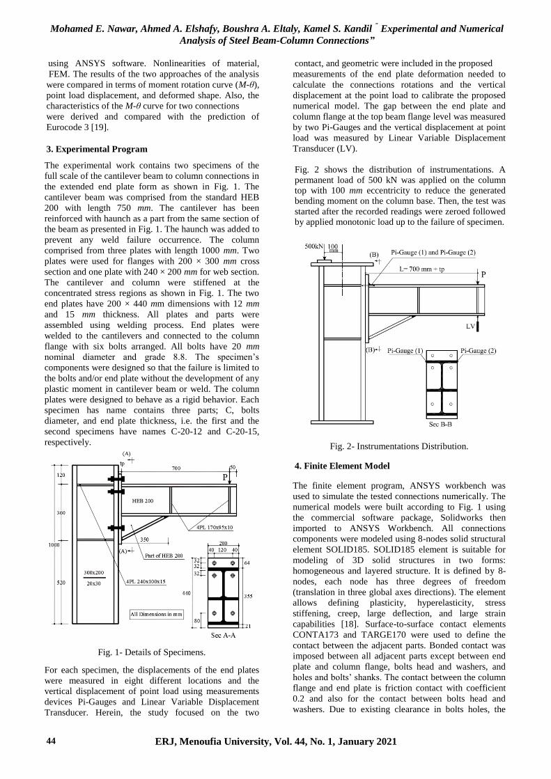
3. Experimental Program The experimental work contains two specimens of the
full scale of the cantilever beam to column connections in
the extended end plate form as shown in Fig. 1. The
cantilever beam was comprised from the standard HEB
200 with length 750 mm. The cantilever has been
reinforced with haunch as a part from the same section of
the beam as presented in Fig. 1. The haunch was added to
prevent any weld failure occurrence. The column
comprised from three plates with length 1000 mm. Two
plates were used for flanges with 200 × 300 mm cross
section and one plate with 240 × 200 mm for web section.
The cantilever and column were stiffened at the
concentrated stress regions as shown in Fig. 1. The two
end plates have 200 × 440 mm dimensions with 12 mm
and 15 mm thickness. All plates and parts were
assembled using welding process. End plates were
welded to the cantilevers and connected to the column
flange with six bolts arranged. All bolts have 20 mm
nominal diameter and grade 8.8. The specimen’s
components were designed so that the failure is limited to
the bolts and/or end plate without the development of any
plastic moment in cantilever beam or weld. The column
plates were designed to behave as a rigid behavior. Each
specimen has name contains three parts; C, bolts
diameter, and end plate thickness, i.e. the first and the
second specimens have names C-20-12 and C-20-15,
respectively.
Fig. 1- Details of Specimens.
For each specimen, the displacements of the end plates
were measured in eight different locations and the
vertical displacement of point load using measurements
devices Pi-Gauges and Linear Variable Displacement
Transducer. Herein, the study focused on the two
measurements of the end plate deformation needed to
calculate the connections rotations and the vertical
displacement at the point load to calibrate the proposed
numerical model. The gap between the end plate and
column flange at the top beam flange level was measured
by two Pi-Gauges and the vertical displacement at point
load was measured by Linear Variable Displacement
Transducer (LV).
Fig. 2 shows the distribution of instrumentations. A permanent load of 500 kN was applied on the column top with 100 mm eccentricity to reduce the generated bending moment on the column base. Then, the test was
started after the recorded readings were zeroed followed by applied monotonic load up to the failure of specimen.
Fig. 2- Instrumentations Distribution. 4. Finite Element Model
The finite element program, ANSYS workbench was
used to simulate the tested connections numerically. The
numerical models were built according to Fig. 1 using
the commercial software package, Solidworks then
imported to ANSYS Workbench. All connections
components were modeled using 8-nodes solid structural
element SOLID185. SOLID185 element is suitable for
modeling of 3D solid structures in two forms:
homogeneous and layered structure. It is defined by 8-
nodes, each node has three degrees of freedom
(translation in three global axes directions). The element
allows defining plasticity, hyperelasticity, stress
stiffening, creep, large deflection, and large strain
capabilities [18]. Surface-to-surface contact elements
CONTA173 and TARGE170 were used to define the
contact between the adjacent parts. Bonded contact was
imposed between all adjacent parts except between end
plate and column flange, bolts head and washers, and
holes and bolts’ shanks. The contact between the column
flange and end plate is friction contact with coefficient
0.2 and also for the contact between bolts head and
washers. Due to existing clearance in bolts holes, the

Mohamed E. Nawar, Ahmed A. Elshafy, Boushra A. Eltaly, Kamel S. Kandil " Experimental and Numerical
Analysis of Steel Beam-Column Connections”
ERJ, Menoufia University, Vol. 44, No. 1, January 2021 45
contact between bolts’ shanks and holes was provided as
frictionless contact. The material properties for each
component of the connections were defined according to
the coupon tensile test as showed in Table 1. Poisson's
ratio was taken as 0.3. The Multilinear kinematic
hardening was used to represent the nonlinear stage of
stress strain curve. The column base was defined as fixed
support in addition to a permanent load 500 kN was
defined on the column top as shown in Fig. 3. The
recorded applied load during the experimental test were
defined to the FEM and the corresponded locations of
two Pi-Gauges and LV were determined.
Table 1- Mechanical Properties of the Connection Components.
Element Part (fy)
(MPa)
(fu)
(MPa)
(E)
(MPa)
εu εf
Column Plate
(Average)
web 250.51 429.61 194,449 0.179 0.236
flange
Beam (Average) web
291.90 439.20 184,650 0.109 0.148 flange
Plates
t = 10 mm 244.17 396.00 181,180 0.13 0.185
t = 12 mm 339.09 492.00 181,260 0.103 0.12
t = 15 mm 352.28 502.72 205,536 0.138 0.192
Bolts D = 20 mm 811.11 942.00 210,000
Fig. 3- Finite Element Model.
5. Results Discussion and Validation
5.1. Specimens Deformation
Figs. 4 and 5 show a comparison between the deformed
shape of the two studied connections due to the
experimental test and the proposal FEM. The comparison
indicates to the validity of the FEM to predict the
behavior of these connections. For specimen C-20-12,
the deformed shape of the connection started with form a
gap between the end plate and the column flange in the
level of beam upper flange. At the end, the end plate in
the upper zone was bent and the upper for bolts were
elongated followed by bending. In addition to, an
extension of the gap up to the level of lower beam flange
is occurred. For specimen C-20-15, the separation
between the end plate and the column flange in the
region between the upper four bolts accompanied by its
elongation was observed at the loading beginning. Then
the separation extended gradually up to the level of the
cantilever bottom flange.
Also, the separation extended up to the upper edge of the
end plate. The maximum gap was observed at the upper
welded edged of the end plate. Shortly before the end, a
slight bending of the upper two bolts occurred. The
relationship between the point load and deflection for
both test and FEM results was shown in Figs. 6 and 7.
The load-deflection curves show that FEM agrees with
the test results with a slight discrepancy in the linear
stage slope does not exceed 5%. As for the nonlinear
stage, there is a bit different in maximum applied load
10% at most.

Mohamed E. Nawar, Ahmed A. Elshafy, Boushra A. Eltaly, Kamel S. Kandil " Experimental and Numerical
Analysis of Steel Beam-Column Connections”
ERJ, Menoufia University, Vol. 44, No. 1, January 2021 46
a) Test
b) FEM
Fig. 4- Deformed Shape of Connection C-20-12.
5.2. Moment-Rotation Relationship
The acting moment on the connection M was taken as
the product of applied load multiplied by the moment
arm (L = 700 mm + thickness of end plate (tp)) as
illustrated in Eq. 1 and Fig. 2.
Rotation of the connections (θ) was determined by
dividing the average recorded readings of two Pi-Gauges
by the lever arm (z) [15, 16] as illustrated in Eq. 2 and
Fig. 8. Lever arm (z) is the distance between mid of the
upper and the bottom beam flange. M-θ curves were
plotted for the two connections according to Eq. 1 and 2.
a) Test.
b) FEM.
Fig. 5- Deformed Shape of Connection C-20-15.
Fig. 6- Applied Load versus Vertical Displacement
Relationship of Specimen C-20-12.

Mohamed E. Nawar, Ahmed A. Elshafy, Boushra A. Eltaly, Kamel S. Kandil " Experimental and Numerical
Analysis of Steel Beam-Column Connections”
ERJ, Menoufia University, Vol. 44, No. 1, January 2021 47
Fig. 7- Applied Load versus Vertical Displacement
Relationship of Specimen C-20-15.
Fig. 8- Parameters of Moment Rotation Relationship.
(1)
Fig. 9 and Fig. 10 show M-θ curve for specimens C-20-
12 and C-20-15 due to the experimental test and the
proposal FEM, respectively. From the two figures, there
is a good agreement between the FEM and the test
results with a slight discrepancy in the slope of the linear
stage of specimen C-20-15 and nonlinear stage of
specimen C-20-12. The characteristics of each M-θ
curve due to the test and FEM were determined
according to Coelho et al. [17] as illustrated in Fig. 11.
Fig. 9- Moment Rotation Relationship of Specimen
C-20-12.
Fig. 10- Moment Rotation Relationship of Specimen
C-20-15.
Also, the main characteristics according to the Eurocode
3; yield moment My, Plastic moment capacity MRd, and
Rotational stiffness Sin, were determined (See Eq. 3, 4,
and 5). Table 2 shows summary and comparison between
the predication of M-θ curve characteristics due to test,
FEM, and Eurocode 3 approach. Also, the table
illustrates the definition of M-θ curve that showed in Fig.
11.
(3)
(4)
(5)
Where: hi is the distance from the bolt-row i to the center
of the bottom flange, Fi is the effective design tension
resistance of bolt-row i, E is the modulus of steel
elasticity, z is the lever arm, and Kn is the stiffness
coefficient for basic joint component n . For more details
about these equations see Eurocode 3 (EN 1993-1-
8:2005) chapter six [19].
Mohamed E. Nawar, Ahmed A. Elshafy, Boushra A. Eltaly, Kamel S. Kandil " Experimental and Numerical
Analysis of Steel Beam-Column Connections”
ERJ, Menoufia University, Vol. 44, No. 1, January 2021 48
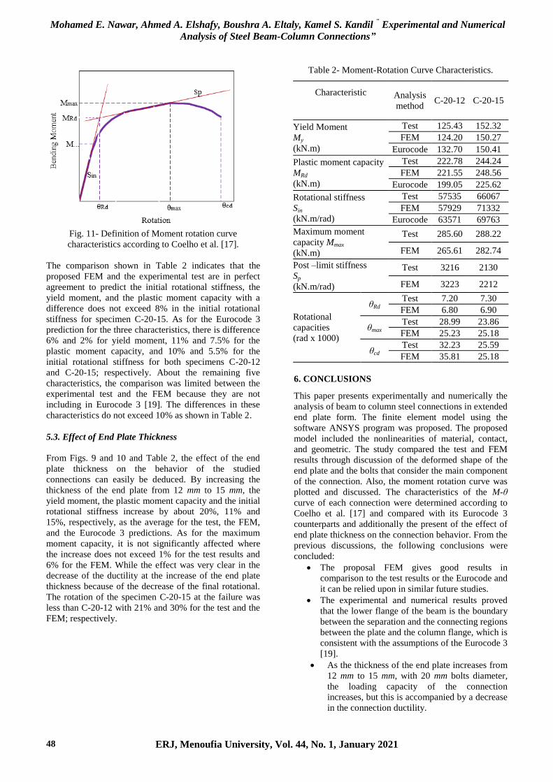
Fig. 11- Definition of Moment rotation curve
characteristics according to Coelho et al. [17].
The comparison shown in Table 2 indicates that the
proposed FEM and the experimental test are in perfect
agreement to predict the initial rotational stiffness, the
yield moment, and the plastic moment capacity with a
difference does not exceed 8% in the initial rotational
stiffness for specimen C-20-15. As for the Eurocode 3
prediction for the three characteristics, there is difference
6% and 2% for yield moment, 11% and 7.5% for the
plastic moment capacity, and 10% and 5.5% for the
initial rotational stiffness for both specimens C-20-12
and C-20-15; respectively. About the remaining five
characteristics, the comparison was limited between the
experimental test and the FEM because they are not
including in Eurocode 3 [19]. The differences in these
characteristics do not exceed 10% as shown in Table 2.
5.3. Effect of End Plate Thickness
From Figs. 9 and 10 and Table 2, the effect of the end
plate thickness on the behavior of the studied
connections can easily be deduced. By increasing the
thickness of the end plate from 12 mm to 15 mm, the
yield moment, the plastic moment capacity and the initial
rotational stiffness increase by about 20%, 11% and
15%, respectively, as the average for the test, the FEM,
and the Eurocode 3 predictions. As for the maximum
moment capacity, it is not significantly affected where
the increase does not exceed 1% for the test results and
6% for the FEM. While the effect was very clear in the
decrease of the ductility at the increase of the end plate
thickness because of the decrease of the final rotational.
The rotation of the specimen C-20-15 at the failure was
less than C-20-12 with 21% and 30% for the test and the
FEM; respectively.
Table 2- Moment-Rotation Curve Characteristics.
Characteristic
Analysis
method C-20-12 C-20-15
Yield Moment
My
(kN.m)
Test 125.43 152.32
FEM 124.20 150.27
Eurocode 132.70 150.41
Plastic moment capacity
MRd
(kN.m)
Test 222.78 244.24
FEM 221.55 248.56
Eurocode 199.05 225.62
Rotational stiffness
Sin
(kN.m/rad)
Test 57535 66067
FEM 57929 71332
Eurocode 63571 69763
Maximum moment
capacity Mmax
(kN.m)
Test 285.60 288.22
FEM 265.61 282.74
Post –limit stiffness
Sp
(kN.m/rad)
Test 3216 2130
FEM 3223 2212
Rotational
capacities
(rad x 1000)
θRd
Test 7.20 7.30
FEM 6.80 6.90
θmax Test 28.99 23.86
FEM 25.23 25.18
θcd Test 32.23 25.59
FEM 35.81 25.18
6. CONCLUSIONS
This paper presents experimentally and numerically the
analysis of beam to column steel connections in extended
end plate form. The finite element model using the
software ANSYS program was proposed. The proposed
model included the nonlinearities of material, contact,
and geometric. The study compared the test and FEM
results through discussion of the deformed shape of the
end plate and the bolts that consider the main component
of the connection. Also, the moment rotation curve was
plotted and discussed. The characteristics of the M-θ
curve of each connection were determined according to
Coelho et al. [17] and compared with its Eurocode 3
counterparts and additionally the present of the effect of
end plate thickness on the connection behavior. From the
previous discussions, the following conclusions were
concluded:
The proposal FEM gives good results in
comparison to the test results or the Eurocode and
it can be relied upon in similar future studies.
The experimental and numerical results proved
that the lower flange of the beam is the boundary
between the separation and the connecting regions
between the plate and the column flange, which is
consistent with the assumptions of the Eurocode 3
[19].
As the thickness of the end plate increases from
12 mm to 15 mm, with 20 mm bolts diameter,
the loading capacity of the connection
increases, but this is accompanied by a decrease
in the connection ductility.

Mohamed E. Nawar, Ahmed A. Elshafy, Boushra A. Eltaly, Kamel S. Kandil " Experimental and Numerical
Analysis of Steel Beam-Column Connections”
ERJ, Menoufia University, Vol. 44, No. 1, January 2021 49
5. References
[1] A. S. Sherbourne and M. R. Bahaari, “3D Simulation
of End-Plate Bolted Connections” Journal of
Structural Engineering, 120 (11), 3122-3136, 1994.
[2] M. R. Mohamadi-Shoorea and M. Mofidb, “Basic
Issues in the Analytical Simulation of Unstiened
Extended End Plate Connection”, Scientia Iranica,
11(4), 303-311, 2004.
[3] C. Díaz, M. Victoria, P. Martí, and O. M. Querin,
“FE model of beam-to-column extended end-plate
joints”, Journal of Constructional Steel Research,
67, 1578–1590, 2011.
[4] R. E. S. Ismail, A.S. Fahmy, A. M. Khalifa, and Y.
M. Mohamed, “Numerical Study on Ultimate
Behavior of Bolted End-Plate Steel Connections”
Latin American Journal of Solids and Structures,
13, 1-22, 2016.
[5] J. Janss, JP. Jaspart, and R. Maquooi. Experimental
study of the non-linear behaviour of beam-to-
column bolted joints. In: Reidar Bjorhovde, Jacques
Brozzetti, AndréColson, editors. Connections in
steel structures: behaviour, strength and design.
Elsevier Ap-plied Science; 1987. p. 26–32.
[6] R. Bai, S. Chan, and J. Hao, “Improved design of
extended end-plate connection allowing for prying
effects”, Journal of Construc-tional Steel Research,
113, 3–27, 2015.
[7] Shi Gang, Static and Seismic Behavior of Semirigid
End-plate Connections in Steel Frames, Tsinghua
University, Beijing, 2004.
[8] S. Chen, C. Chao Zhou and Z. Wang,
“Experimental Study and Comparative Numerical
Analysis of the Mechanical Behavior of Extended
End-Plate Connections with End-Plate Stiffeners”,
The Open Mechanical Engineering Journal, 9, 653-
665, 2015.
[9] EA. Sumner. Unified design of extended end-plate
moment con-nections subject to cyclic loading.
PhD thesis. Virginia Polytechnic Institute and State
University, USA; 2003.
[10] A. H. Salem, E. Y. Sayed-Ahmed, A. A. El-Serwi,
and R. A. Aziz, “Behavior and Design of I-Beam-
To-Column Connections: Extended Rigid Bolted
Connections”, EUROSTEEL 2014, Naples, Italy,
September 10-12, 2014.
[11] A. H. Salem, E. Y. Sayed-Ahmed, A. A. El-Serwi,
and R. A. Aziz, “Behavior and Design of I-Beam-
To-Column Connections: Flushed Rigid Bolted
Connections”, EUROSTEEL 2014, Naples, Italy,
September 10-12, 2014.
[12] L. Louis and N. Babu, “Numerical Analysis of
Strength Behavior of Bolted Steel Beam Column
Connection Based on Type and Position of
Stiffeners”, International Research Journal of
Engineering and Technology (IRJET), 4(4), 3205-
3211, 2017.
[13] R. A. Samaan, A. I. El-Serwi, and R. A. El-Hadary,
“Experimental and theoretical study of large
capacity extended end-plate moment connection”,
EUROSTEEL 2017, Copenhagen, Denmark,
September 13–15, 2017.
[14] V. Zeinoddini-Meimand, M. Ghassemieh, and J.
Kiani, “Finite Element Analysis of Flush End Plate
Moment Connections under Cyclic Loading”
International Journal of Civil and Environmental
Engineering, 8(1), 96-104, 2014.
[15] G. Shi, YJ. Shi and YQ. Wang “Behavior of end-
plate moment connections under earthquake
loading”. Engineering Structures, 29(5), 29(5):703–
716, 2007.
[16] G. Shi, Y. Shi, Y. Wang, and F. S. K. Bijlaard,
“Monotonic loading tests on semi-rigid end-plate
connections with welded I-shaped columns and
beams”, Advances in Structural Engineering, 13(2),
215-230, 2010.
[17] A. Coelho, F. Bijlaard, and L. Silva, “Experimental
assessment of the ductility of extended end plate
connections”, Engineering Structures, 26, 1185-
1206, 2004.
[18] ANSYS Workbench Help, Version 19.
[19] European Committee for Standardization (CEN).
Eurocode 3. Design of steel structures, Part 1–8:
design of joints (EN 1993-1-8:2005), 2005.
Brussels.
[20] D. Abdelrahim, Y. Ahmed and I. Mohamed,
“Behavior of I-beam bolted extended end-plate
moment connections”, Ain Shams Engineering
Journal, 4, 685–699, 2013.


