


CELTIC MINERALS LTD.
3rd Year Assessment Report
Garland Lake Property Licence 10971M
Northern Labrador
April 2008
Elliott Stuckless, BSc &
Mark Graves, P. Geo
Total Expenditures: $ 518, 291.48

Garland Lake Property Celtic Minerals Ltd. 3rd Year Assessment
TABLE OF CONTENTS
Page #
1.0 Introduction 4 2.0 Location, Access & Physiography 4 3.0 History of Land Tenure & Exploration 4 4.0 Geology 13
4.1 Regional Geology 13 4.2 Property Geology 15
5.0 2007 Diamond Drilling Program 18
5.1 Description and Implementation 18 5.2 Results 22 5.3 Recommendations and Future Plans 22 5.4 List of Expenditures 27
6.0 References 28
LIST OF APPENDICIES
Appendix 1 Diamond Drill Logs Appendix 2 Borehole UTEM Preliminary Report

Garland Lake Property Celtic Minerals Ltd. 3rd Year Assessment
LIST OF FIGURES
Page #
FIGURE 1 Property Location Map 5 FIGURE 2 Claims Location Map 6 FIGURE 3 Labrador Geology Map 14 FIGURE 4 Nain Plutonic Suite Geology 16 FIGURE 5 Geophysical Summary 19 FIGURE 6 AGG Survey Results 20 FIGURE 7 MT Survey Results 21 FIGURE 8 Proposed DDH Location Map 23 FIGURE 9 DDH GL‐07‐01 Cross Section with MT 24 FIGURE 10 DDH GL‐07‐02 Cross Section with MT 25 FIGURE 11 DDH GL‐07‐01 Geological Cross Section 26
LIST OF TABLES
TABLE 1 Licence Description and Status 7

Garland Lake Property Celtic Minerals Ltd. 3rd Year Assessment
1.0 INTRODUCTION Celtic Minerals Ltd. Recently completed an 801.01m diamond drilling program at the Garland Lake Property in northern Labrador. The program was designed to test a Magnetotelluric anomaly delineated during the 2006 campaign, located on the flanks of a gravity high local to a known prospect exhibiting similar geological features to those found at the Voisey’s Bay Mine. The target for the hole was magmatic base‐metal (Ni‐Cu‐Co) sulphide mineralization similar to that being mined at the Voisey’s Bay Mine, approximately 45km northwest of the proposed drill locations. The following report will detail results of this program as well as provide recommendations for future work.
2.0 LOCATION, ACCESS & PHYSIOGRAPHY The Garland Lake Property is located on NTS map sheets 14C/04 and 13N/13, approximately 37 km southeast of the Voisey’s Bay nickel deposit. The nearest settlements are the towns of Nain, located 55km to the North and Natuashish located 30km to the southeast (Figure 1). Both of these communities are accessible via aircraft from the town of Goose Bay, located 360km southeast of the property. The claim area is located within Labrador Settlement Inuit Lands of the new Canadian territory of Nunatsiavut within the province of Newfoundland and Labrador currently covered by a land claims agreement between the Labrador Inuit Association and the federal and provincial governments. The property is also believed to be within lands under negotiation for land claims agreements with the Innu Nation of Labrador. Access to the Garland Lake property is limited to helicopter, with numerous staging areas located within the claim area, as well as snowmobile during the winter months.
The property exhibits rocky ridges and plateaus separated by deeply incised valleys and steep bluffs. Relief on the property ranges between 20 m and 350 m above sea level and the property is located immediately north of the regionally extensive Notakwanon River, which flows eastward into Merrifield Bay. Hilltops and steep slopes provide abundant outcrop exposure, whereas valleys are forested by spruce and tamarack or covered by bogs and ponds 3.0 HISTORY OF LAND TENURE & EXPLORATION The Garland Lake property consists of three licences (10970M, 10971M and 11257M), which are comprised of 210 claims totaling 52.5 km2 (Figure 2). Table 1 describes the current licence status.

8888888888888888888888888888888888888888888888888888888888888888888888888888888888
GARLAND LAKEGARLAND LAKEGARLAND LAKEGARLAND LAKEGARLAND LAKEGARLAND LAKEGARLAND LAKEGARLAND LAKEGARLAND LAKEPROPERTYPROPERTYPROPERTYPROPERTYPROPERTYPROPERTYPROPERTYPROPERTYPROPERTY
((((((((((((((((((((((((((((((((((((((((((((((((( Goose BayGoose BayGoose BayGoose BayGoose BayGoose BayGoose BayGoose BayGoose Bay
NainNainNainNainNainNainNainNainNain(((((((((((((((((((((((((((((((((((((((((((((((((
((((((((((((((((((((((((((((((((((((((((((((((((( Labrador CityLabrador CityLabrador CityLabrador CityLabrador CityLabrador CityLabrador CityLabrador CityLabrador City
((((((((((((((((((((((((((((((((((((((((((((((((( NatuashishNatuashishNatuashishNatuashishNatuashishNatuashishNatuashishNatuashishNatuashish
Scale: 1:5,000,000
Drawn By: EMS
Figure: 1
Projection: NAD 27
Celtic Minerals Ltd.Garland Lake Property
Location Map-100
Kilometres
0 100 200

590000°E590000°E590000°E590000°E590000°E590000°E590000°E590000°E590000°E
585000°E585000°E585000°E585000°E585000°E585000°E585000°E585000°E585000°E
580000°E580000°E580000°E580000°E580000°E580000°E580000°E580000°E580000°E
575000°E575000°E575000°E575000°E575000°E575000°E575000°E575000°E575000°E
570000°E570000°E570000°E570000°E570000°E570000°E570000°E570000°E570000°E
6205000°N6205000°N6205000°N6205000°N6205000°N6205000°N6205000°N6205000°N6205000°N
6215000°N6215000°N6215000°N6215000°N6215000°N6215000°N6215000°N6215000°N6215000°N
6210000°N6210000°N6210000°N6210000°N6210000°N6210000°N6210000°N6210000°N6210000°N
Scale: 1; 100,000
NAD 27 - Zone 20
Figure: 2
NTS: 14C/04
Celtic Minerals Ltd.Garland Lake Property
Claims MapCeltic Minerals Claims -2
Kilometres
0 2 4
10970M10970M10970M10970M10970M10970M10970M10970M10970M10970M10970M10970M10970M10970M10970M10970M10970M10970M10970M10970M10970M10970M10970M10970M10970M10970M10970M10970M10970M10970M10970M10970M10970M10970M10970M10970M10970M10970M10970M10970M10970M10970M10970M10970M10970M10970M10970M10970M10970M10970M10970M10970M10970M10970M10970M10970M10970M10970M10970M10970M10970M10970M10970M10970M10970M
10971M10971M10971M10971M10971M10971M10971M10971M10971M10971M10971M10971M10971M10971M10971M10971M10971M10971M10971M10971M10971M10971M10971M10971M10971M10971M10971M10971M10971M10971M10971M10971M10971M10971M10971M10971M10971M10971M10971M10971M10971M10971M10971M10971M10971M10971M10971M10971M10971M10971M10971M10971M10971M10971M10971M10971M10971M10971M10971M10971M10971M10971M10971M10971M10971M 11257M11257M11257M11257M11257M11257M11257M11257M11257M11257M11257M11257M11257M11257M11257M11257M11257M11257M11257M11257M11257M11257M11257M11257M11257M11257M11257M11257M11257M11257M11257M11257M11257M11257M11257M11257M11257M11257M11257M11257M11257M11257M11257M11257M11257M11257M11257M11257M11257M11257M11257M11257M11257M11257M11257M11257M11257M11257M11257M11257M11257M11257M11257M11257M11257M

Garland Lake Property Celtic Minerals Ltd. 3rd Year Assessment
Table 1: Licence Description LICENCE CLAIMS LICENCE HOLDER ISSUANCE REPORT DUE 10970M 10971M 11257M
103 47 60
Cornerstone Resources Inc. Cornerstone Resources Inc. Cornerstone Resources Inc.
June 1, 2005 June 1, 2005 Sept. 23, 2005
July 31, 2008 July 31, 2008 Nov. 24, 2008
Prior to Cornerstone acquiring the project, work on the property was largely limited to reconnaissance geological mapping described above as well as regional geochemical surveys conducted by provincial and federal government agencies (Friske et al., 1993, Davenport et al., 1999). This work failed to detect Ni in lake sediment anomalies or sulphide showings within the current property. Prior to 1995 and the “Voisey’s Bay rush”, there is no record of any previous mineral exploration within the current property. Following the announcement of the discovery in the fall of 1994, a boom in exploration activity ensued and new exploration was conducted throughout Labrador, including the area of the Garland property. Previous exploration completed within the current property is limited to helicopter airborne electromagnetic and magnetic surveys, limited audiomagnetotelluric (AMT) geophysical surveys, and follow‐up reconnaissance style prospecting and mapping. No diamond drilling is known to have been conducted within the property or the immediate surrounding area. Inco’s intervening Garland Lake property has received more detailed exploration work including geological mapping and ground audiomagnetotellurics (AMT) geophysical surveys (Morrison, 2001). Results generated by Inco are considered significant as they report discovery of a prospect called the Plugger Hill prospect which they describe as being comprised of troctolitic rocks hosting variably digested paragneiss (Tasiuyak Gneiss) xenoliths as well as disseminated concentrations of magmatic sulphides. On this basis, they consider the prospect to host key characteristics of the Voisey’s Bay deposits (Morrison, 2001). Results generated by their AMT surveys are also considered significant as this survey detected a series of northwest trending, deep, AMT anomalies defined as a series of 400 to 800 m wide zones of increased conductivity at depths ranging between 800 and 1,500 m. These anomalies remain untested and unexplained and may be related to concentrations of magmatic sulphides. Rock samples collected by Inco at the Plugger Hill prospect are reported to have returned assays of up to 0.02% Ni, 0.04% Cu, 0.016% Co and 1.07% S from troctolite containing disseminated sulphides (Morrison, 2001). A brief summary of exploration activity conducted by Inco and others within the current property and surrounding area is provided below with summary details presented by company and individual assessment report as filed with the government of Newfoundland and Labrador.

Garland Lake Property Celtic Minerals Ltd. 3rd Year Assessment
Cominco Ltd., Licences 905M, 906M 907M (Grosl and Rickli, 1995; file LAB/1145) (Cominco Merrifield and Tasialuk properties, located immediately east of Cornerstone licences 10970M and 11257M) During the summer of 1995, Cominco completed reconnaissance style stream silt and soil sampling, helicopter airborne geophysical surveys, limited mapping and prospecting over their property. No significant results were returned from that portion of their property that occurs within Cornerstone’s current property. Highlights include identification of sulphide showings within anorthositic rocks east of the Notakwanon River where it enters Merrifield Bay that returned assays of up to 1,540 ppm Cu, 90 ppm Co, and 2,200 ppm Ni (approximately 2.7 km east of licence 11257M). The airborne survey failed to detect any conductors on that portion of the property currently held by Cornerstone. No further work was recommended. Absolut Resources Corp., Licence 918M (MacGillivray, 1996; file LAB/1156) (Absolut Project Area 14, covers northeast corner of Cornerstone licence 10970M and extends northward off current property) During the summer of 1995, Absolut completed helicopter airborne geophysical surveys and limited mapping and prospecting over the property. The airborne survey failed to detect any significant conductors and prospecting failed to identify sulphide mineralization. Mapping confirmed the northeast corner of Cornerstone licence 10970M to be underlain by anorthosite. No further work was recommended. Aranlee Resources & NDT Ventures Ltd., Licence 1146M (Burns et al., 1996; file LAB/1190) (NDT Project 69‐1, covers northwest corner of Cornerstone licence 10970M and extends westward off current property) During the summer of 1995, NDT Ventures Ltd. in joint venture with Aranlee Resources Ltd., completed helicopter airborne geophysical surveys and limited mapping and prospecting over the property. The airborne survey failed to detect any significant conductors and prospecting failed to identify sulphide mineralization. Mapping confirmed the northwest corner of Cornerstone licence 10970M to be underlain by anorthosite. No further work was recommended. NDT Ventures Limited and Layfield Resources Inc., Licence 1461M (Burns et al., 1996, file LAB/1189 & LAB/1250) (NDT Project 74‐4, covers west end of Cornerstone licence 10971M) During the summer of 1995, NDT Ventures Ltd. in joint venture with Layfield Resources Inc., completed helicopter airborne geophysical surveys and limited mapping and prospecting over the property. The airborne survey failed to detect any significant conductors and prospecting failed to identify sulphide mineralization. No further work was recommended.

Garland Lake Property Celtic Minerals Ltd. 3rd Year Assessment
United Compass Resources Ltd.., Licence 1194M (Wares et al., 1995; files LAB/1221, LAB/1341, & LAB/1146) (United Compass Kogaluk River Property, covers central portion of Cornerstone licence 10970M and extends northward off current property) During the summer of 1995, United Compass Resources completed stream silt sampling, helicopter airborne geophysical surveys, limited mapping and prospecting over the property. The airborne survey failed to detect any conductors on that portion of the property covering Cornerstone licence 10970M. Stream silt sampling and prospecting failed to return anomalous base metal values from rocks or stream silts and no sulphide showings were identified within that portion of the property within Cornerstone licence 10970M. Several magnetic to conductive anomalies were identified northwest of the licence 10970M and follow up field investigations were recommended to assess these anomalies. Cartaway Resources Corporation, Licences 2526M, 2527M, 2829M, 2830M, 3082M, 3085M (Beesley, T.J., and Woolham, 1997; file LAB/1218) (property covers portions of both Cornerstone licences 10970M and 10971M as well as Inco’s Plugger Hill prospect) During the summer of 1995, Cartaway conducted prospecting and helicopter EM/Mag surveys throughout much of the area of the current Cornerstone Property and Inco’s Plugger Hill prospect. Cartaway’s property was optioned from Freeport Resources who still retain a small licence (licence 6113M) in the area. Results include identification of flat‐lying and mineralized leucogabbro and olivine gabbro sills at Plugger Hill and extending onto the current Freeport property (licence 6113M to the northwest). Cartaway describe these results from their licence 2527M as follows:
“Rusty gossan zones were noted within basement gneiss and Nain Plutonic Suite mafic rocks and these were sampled and analysed for copper‐nickel‐cobalt content….A gossanous patch in leucogabbro 0.3 m in diameter was sampled and contained 1,180 ppm Cu, 1,361 ppm Ni, and 526 ppm Co.. This gossan was in the vicinity of a 2 m‐wide by 20 m‐long disseminated sulphide zone (pyrite, pyrrhotite, trace chalcopyrite. A sample from this zone contained 386 ppm Cu, 377 ppm nickel, 151 ppm cobalt”.
The description of this mineralization suggest a link with the Plugger Hill prospect. Results of the helicopter geophysical surveys included detection of several conductive anomalies; most of which were interpreted to be associated with topographic or overburden features, however at least two potentially interesting anomalies were detected and were interpreted to be related with flat‐lying conductive features in part correlative with the lake bottom of a large lake located on the northwest corner of

Garland Lake Property Celtic Minerals Ltd. 3rd Year Assessment
Cornerstone licence 10970M. Cartaway interpreted these conductors to be too conductive to be explained by typical conductive lake bottom sediments. Further work was recommended and completed in September and October 1997. The results of which are described below (Cartaway assessment file 014C/04/0096). Cartaway Resources Corporation, Licence 2527M (Clarke, E. J., 1997; file 014C/04/0096) (property covers portions of both Cornerstone licence 10970M & Freeport’s licence 6113M) During the September and October of 1997, Cartaway conducted additional prospecting and geological mapping to assess mineralization and gabbro identified in 1995 (Beesley and Woolham, 1997). This work mapped out an extensive area of gabbro in contact with underlying Tasiuyak Gneiss in the area surrounding a prominent, hook‐shaped lake located within Freeport’s current licence 6113M. Of note is their description of the gneiss in this area which Clarke (1997) describes as follows:
The gneisses …are composed predominantly of white‐grey weathering, medium‐coarse grained, granoblastic, locally migmatized, granulite facies quartzo‐feldspathic+garnet+cordierite gneiss. This gneiss is commonly ribbon‐textured with locally abundant 0.5‐5cm, brown weathering, garnet porphyroblasts. The larger garnets are usually retrogressed to cordierite with hypersthene rims and inclusions. A spectacular feature of this gneiss is their abundance of purple garnet and cordierite that locally forms up to 50% of the rock volume in anastomosing layers of fine‐grained aggregates.
In describing the gabbro Clarke provides the following description: In many locations the gabbro contains large, angular blocks of coarse‐grained dark grey anorthosite…Generally within 10 m of the contact with the gneiss, the gabbro often contains up to 10% 1‐5 mm, ovoidal quartz eyes. In a couple of locations towards the eastern margin of the property, the gabbro has been contaminated by enough quartzo‐feldspathic gneiss to be classified as a granodiorite…To the west of the hook‐shaped lake in the centre of the property, the gabbro appears to contain a greater percentage of oxide phases and may represent a separate phase of the intrusion.
Additional sampling showed anomalous mineralization occurred at the gabbro’s basal contact but failed to return significant base metal values greater than that returned by previous work (Beesley and Woolham, 1997) and the best assay returned from mineralized gabbro contained 565 ppm Ni, 2,041 ppm Cu, 281 ppm Co, and 5.83% S.

Garland Lake Property Celtic Minerals Ltd. 3rd Year Assessment
Despite recognizing the property hosted an environment considered favourable for discovery Voisey’s Bay type mineralization, no further work was recommended. New Claymore Resources Ltd. And Troymin Resources Ltd., Licence 2865M (Chapman and van Damme, 1995; file 014C/04/0075) (New Claymore L Property, covers east half of Cornerstone licence 10970M and extends south to Plugger Hill prospect) During the summer of 1995, New Claymore completed limited prospecting and mapping, and stream sediment sampling. The work failed to yield significant results and focused on the northern portion of their property (work was conducted north of the Plugger Hill prospect). Mapping is reported to have identified a 100 to 200 m wide gabbro dyke possessing plagioclase clusters as well as pyroxene, biotite, magnetite and olivine. The plagioclase aggregates are described as locally defining diffuse layers and New Claymore speculated that this body was a genetic relative of the Cabot Lake ferrodiorite (large sheet‐like body of ferrodiorite mapped 20 km southwest of the Voisey’s Bay mine). Rock and stream sediment sampling failed to return anomalous Ni values; however, further work was recommended, including helicopter airborne geophysical surveys. A Cornerstone field crew visited the reported site of the 100‐200 m wide gabbro dyke during the summer of 2005, but failed to identify such a rock type but rather encountered only coarse grained anorthosite and leuconorite. Westpine Metal Ltd., Licence 3726M (Hattie et al., 1997; file LAB/1225, Appendix VIII) (Westpine Project VB‐8, covers most of Garland Lake, no overlap with current Cornerstone licences) During the summer of 1995, Westpine completed reconnaissance mapping and prospecting around Garland Lake. Mapping identified anorthosite and monzodiorite of the Nain Plutonic Suite as well as orthogneiss on the southern shore of the lake. No further work was recommended. Freeport Resources Inc., Licence 5584M (Nichols and Nikols, 1998; file 013N/0120) (property covers portions of both Cornerstone licence 10970M & Freeport’s licence 6113M) In 1997, Freeport attempted to complete additional work on the property, but were unable to reach the property due to poor weather. Expenditures were filed for assessment though no additional data was collected from the property. Further work is reported to have been completed by Freeport in subsequent years, but is not in the public domain at time of writing this report. The recent work was reported in a Year 10 assessment report filed in October 2005 consisting of compilation and geology and a Year 11 assessment report consisting of ground geophysics (re‐interpretation of Inco’s audio‐magnetotelluric survey), also filed in October 2005. Inco Limited, Licences 7654M‐7657M (Morrison, G.G., 2001; file LAB/1406)

Garland Lake Property Celtic Minerals Ltd. 3rd Year Assessment
(original 1,001 claim property covered Inco’s licence 7655 (Plugger Hill prospect) as well as portions of Cornerstone licences 10970M & 10971M) During the fall of 2000, Inco completed geological mapping and prospecting as well as ground based audiomagnetotelluric (AMT) surveys over a central portion of a large 1,001 claim (250.25 km2) property originally staked in August of 2000. No rational was given for the staking of ground in this area, much of which was previously controlled by Freeport Resources and allowed to lapse due to insufficient assessment credits. Results generated by Inco are considered significant as they report discovery of a prospect called the Plugger Hill prospect which they describe as being comprised of troctolitic rocks hosting variably digested paragneiss (Tasiuyak Gneiss) xenoliths as well as disseminated concentrations of magmatic sulphides. On this basis, Inco considered the prospect to host key characteristics of the Voisey’s Bay deposits (Morrison, 2001). Results generated by the AMT surveys are also considered significant as the survey detected a series of northwest trending, deep, AMT anomalies defined as a series of 400 to 800 m wide zones of increased conductivity at depths ranging between 800 and 1,500 m. These anomalies remain untested and unexplained and may be related to concentrations of magmatic sulphides. Rock samples collected by Inco at the Plugger Hill prospect are reported to have returned assays of up to 0.02% Ni, 0.04% Cu, 0.016% Co and 1.07% S from troctolite containing disseminated sulphides (Morrison, 2001). In addition to the findings discussed above, Inco completed geological mapping of their property covering licence 7655M as well as the surrounding area including the majority of Cornerstone’s land position including licences 10970M, 10971M and 11257M. Of note was that Inco mapped several outcropping bodies of troctolite and olivine gabbro on licences 10970M and 10971M. These locations were investigated by Cornerstone in 2005 and were remapped as being composed of leuconorite and/or fine to medium grained monzogabbro to ferrodiorite After filing the work mentioned above in 2001, Inco allowed the project to lie dormant until 2005 and allowed a large portion of the property to lapse on the property’s first anniversary (fall 2001). Inco maintained only one of its four original licences, maintaining 251 claims within licence 7655M. In August 2005, Inco staked additional property surrounding licence (7655M) and extending northwest to Voisey’s Bay. At time of writing this report, additional exploration work is known to have been completed on licence 7655M by Inco since 2001, though the data is not yet in the public domain. A brief description of this work is available from Mineral Licence Inquiries issued by the Newfoundland and Labrador Department of Mines and Energy and indicates Inco completed additional ground geophysics (UTEM surveys) prior to August, 2005 as well as lithogeochemical sampling and vertical loop EM surveys prior to November 2005. Comments made by Inco in the media suggested they planned to complete additional work within licence (7655M) as well as the surrounding licences during 2006. Part of this work included an airborne gravity gradiometry survey to be

Garland Lake Property Celtic Minerals Ltd. 3rd Year Assessment
completed over the entire land position acquired in August 2005 as well as portions of the Voisey’s Bay Mining Lease. Several junior companies agreed to extend the survey over their adjoining properties and share data with Inco. 4.0 GEOLOGY
4.1 Regional Geology (After Ryan et al., 1995) The property is located within the Nain Plutonic Suite (Figure 3) close to the inferred boundary or “suture” between the eastern edge of the southeastern Churchill Province and western margin of the Nain Province (e.g. Ryan, 1990). These provinces are interpreted to represent vestiges of two cratonic masses known as the Rae (Churchill Province) and North Atlantic (Nain Province) cratons that converged and collided during the Paleoproterozoic (1.85 Ga) Torngat Orogen (Wardle et al., 1990). A belt of pelitic, granulite facies, metasedimentary paragneiss known as the Tasiuyak gneiss, lies to the west of the Nain‐Churchill boundary along much of its length and partly coincides with a 1.85 to 1.82 Ga major structural zone known as the Abloviak shear zone (Bertrand et al., 1993). The 1350 to 1290 Ma Nain Plutonic Suite and 1450 Ma Harp Lake intrusion were emplaced across this boundary zone (e.g. Emslie, 1980, Emslie et al., 1994) and are largely unaffected by later tectonic events. In addition to the Tasiuyak gneiss, rocks of the eastern Churchill Province in Labrador are primarily comprised of a variety of reworked Archean and Paleoproterozoic gneisses predominantly derived from igneous protoliths ranging in composition from tonalitic to granitic, as well as lesser supracrustal rocks. The latter include units of mafic gneiss and paragneiss (e.g., Ryan, 1990). Rocks of the eastern Churchill Province in north‐central Labrador are amphibolite to granulite facies and include gneisses and associated foliated plutonic rocks generated during development of the Paleoproterozoic Torngat Orogen locally interleaved with re‐worked Archean crust (ca. 2800 ‐ 2600 Ma) (e.g. Ryan and Kerr, 2005). Rocks of the Nain Province are interpreted to represent a westward extension of those found along the west coast of south‐central Greenland, representing the westernmost remnant of the fragmented North Atlantic Craton (e.g. Ryan and Kerr, 2005). In Labrador, these rocks are polydeformed, amphibolite‐ to granulite‐facies gneisses of which the largest component comprises quartzofeldspathic gneisses derived from plutonic protoliths. Interlayered with these felsic orthogneisses are other gneisses derived from layered basic intrusions as well as from sedimentary and volcanic rocks (e.g., Ryan and Kerr, 2005). Rocks of the Nain Plutonic Suite (NPS) straddle the boundary between the Nain and Churchill provinces (Figure 3) and are interpreted to represent a Mesoproterozoic,

Figure 3.
After Kerr, 2003.
KKââuukk
OOkkaakk
KKoonnrraadd
GGaarrllaanndd
NNoottaakkwwaannoonn

Garland Lake Property Celtic Minerals Ltd. 3rd Year Assessment
anorogenic batholithic igneous complex composed mainly of anorthosite and granite as well as lesser volumes of troctolitic and ferrodioritic rocks ranging in age from 1.34 to 1.29 Ga (e.g. Ryan, 1996). Of these, only troctolitic to gabbroic phases of the NPS are considered to represent mantle‐derived melts suitable for the accumulation of nickel‐rich, magmatic sulphide deposits akin to those that host the Voisey’s Bay mine (e.g. Ryan et al., 1995). One such troctolite body, known as the Voisey’s Bay Intrusion, is among the oldest and most primitive pulses of NPS magma (Amelin et al., 1997), and is host to the magmatic nickel sulphide deposits at Voisey’s Bay. At Voisey’s Bay, magmatic nickel sulphide deposits discovered to date represent a combined resource of 94 Mt averaging 2.06% Ni, 1.03% Cu & 0.11% Co (Inco 2004 Annual Report). This resource is hosted by an east‐west striking, dyke‐chamber complex of several sub‐chambers of troctolitic olivine gabbro connected by dyke‐like bodies or feeders interpreted to have served as favourable sites for sulphide accumulation by fluid flow dynamics, particularly at the entry points of feeder dykes into larger sub‐chambers (e.g., Naldrett et al., 1996; Evans‐Lamswood et al., 2000). At present, this mineralized magmatic system is known to extend over a minimum strike length of 11 km (Voisey’s Bay Nickel, 2004; website, reserves & resources) and remains open to the east. The system is cut off at surface to the west by a younger intrusion of quartz monzonite and granite known as the Makhavinekh Lake Granite (Ryan and Lee, 1986) dated at 1322 + 1 Ma (Krogh and Heaman, 1989). The eastern portion of the Voisey’s Bay Intrusion (troctolite) is intruded by granitic rocks of the Voisey’s Bay Granite (Figure 4) dated at 1305 Ma (Amelin et al., 1997). A large body of granitic rocks known as the Notakwanon River Pluton is located south of Voisey’s Bay and has been interpreted to potentially represent an extension of the Voisey’s Bay Granite (e.g., Ryan, 1990). One phase of the Notakwanon River Pluton was subsequently dated at 1292±4 Ma (Ryan et al., 1991) and based on textural evidence discussed in Ryan and Lee (1986) and Ryan pers. com. (2006) and the aforementioned age dates it’s suspected that the Voisey’s Bay Granite and the Notakwanon River Pluton represent at least two different bodies or batholiths.
4.2 Property Geology The most complete mapping of the property is that of the Newfoundland and Labrador Geological Survey, who mapped the southern part of the property at a scale of 1:100,000 (Hill, 1982) and the GSC who mapped the north part of the property at 1:250,000 scale Taylor, (1977). This work has since been recompiled and supplemented by work from additional sources as compiled geology maps by Ryan (1990) and Wardle (1993). The latter maps interpret the entire property to be underlain by anorthositic and granitic to monzonitic intrusive rock of the Nain Plutonic Suite as summarized in Figure 4.

GGaarrllaanndd LLaakkee PPrrooppeerrttyy
Figure 4. General geology map of the Nain Plutonic Suite and surrounding region showing magmatic sulphide occurrences and location of the Garland Lake project. Note small wedge of Nain Province gneiss located ~5 km southwest of the Garland Lake property’s southern licence and described further in report text. After Ryan and Kerr, 2000.
NNoottaakkwwaannoonn RRiivveerr bbaatthhoolliitthh
VVooiisseeyy’’ss BBaayy ggrraanniittee
GGaarrllaanndd BBiigghhtt aannoorrtthhoossiittee
PPlluuggggeerr HHiillll PPrroossppeecctt

Garland Lake Property Celtic Minerals Ltd. 3rd Year Assessment
Granitic rocks underlying the property are correlated with the Notakwanon River Batholith while anorthositic rocks occur as two spatially discrete but potentially related bodies, whereby the northern body underlying the northern portion of the property is an unnamed body (Ryan (1990) and the southern anorthositic body partially underlying the southern licences is referred to as the Tunungayualuk Island Leuconorite (Ryan, 1990). Monzonitic to granitic rocks of the Notakwanon River Batholith are described by Ryan (1990) with other granitic members of the Nain Plutonic Suite as being composed of predominantly hornblende ± biotite ± fayalite ± clinopyroxene ± fluorite‐bearing granite and quartz monzonite, but also includes monzonite, syenite, monzodiorite and quartz monzodiorite. Unlike other granitic bodies of the Nain Plutonic Suite, the Notakwanon River Batholith and the Voisey’s Bay Granite lack obvious development of rapakivi texture (ovoidal plagioclase‐mantled potassium feldspar megacrysts). Portions of the Notakwanon River Batholith west of the property are mapped as having finer grained porphyritic textures and are mapped as porphyry (Ryan and Lee, 1986), suggesting a shallower level of intrusion to the west (Ryan, 1990; pers. com. 2006). The unnamed anorthositic body underlying the northern portion of the Garland Lake Property is informally referred to here as the Garland Bight Anorthosite and is collectively described by Ryan (1990) with other anorthositic members of the Nain Plutonic Suite as being composed of predominantly medium to coarse grained norite, leuconorite and anorthosite. The Tunungayualuk Island Leuconorite underlying the southern margin of the Garland Lake Property is described (Ryan, 1990) as being composed of massive to layered leuconorite. In addition to the intrusive rocks mapped within the property, there is an exposure of tonalitic gneiss straddling the boundary between the Notakwanon River Batholith and the Tunungayualuk Island Leuconorite (Ryan, 1990 & Wardle, 1993) west of Cornerstone’s southern licences (partially shown on Figure 4). This gneiss has been correlated by Ryan (1990) as part of the Nain Province, while Wardle (1993) correlates these gneisses with Archean tonalitic gneiss of the Eastern Churchill Province that represent structurally reworked equivalents of Nain Province gneisses to the east. On this basis, it can be speculated that the Garland property is located proximal to the “suture” between the Nain and Churchill structural provinces, though the precise location of this boundary is notknown. This relationship is further highlighted by more recent mapping conducted by Inco (Morrison, 2001) who mapped an occurrence of troctolite hosting breccia fragments reportedly composed of Tasiuyak Gneiss. This occurrence is known as the Plugger Hill Prospect (Figure 4).

Garland Lake Property Celtic Minerals Ltd. 3rd Year Assessment
5.0 2007 DIAMOND DRILLING PROGRAM
5.1 Description and Implementation
Mineralization at Voisey’s Bay occurs associated with and within troctolitic rocks of the Voisey Bay Intrusion. This body straddles the suture between the Nain and Churchill structural provinces although it is debated whether the suture was instrumental in developing the deposit. Mafic, typically olivine‐bearing, rocks of the Nain Plutonic Suite are considered to have the most potential to host magmatic sulphide deposits. The Garland Lake Property is considered to similarly straddle or occur proximal to the above suture although the exact location of the suture is unknown. Troctolitic rocks have been mapped in the area and the Plugger Hill Prospect of INCO, situated between the two sets of claims optioned by Celtic, is being actively explored. Their exploration efforts indicate that the prospect includes features similar to those seen at the Voisey’s Bay Mine. These features include a troctolitic host to disseminated sulphide mineralization with values up to 0.02% Ni, 0.04% Cu, 0.016% Co and 1.07% S and xenoliths of variably digested paragneiss, a feature particularly linked with the Eastern Deeps deposit. As well gravity, AMT and interpreted northwest structural features continue to upgrade the potential of the area and the individual targets anomalies (Figure 5). The Plugger Hill Prospect occurs approximately 8.5km northwest of the proposed diamond drill project. During 2006 Celtic Minerals Ltd received data from a detailed airborne gravity gradiometry survey performed by Inco Ltd covering their claims in the area as well as the Garland Lakes claims owned by Cornerstone Resources Inc and now under option by Celtic Minerals Ltd. (Figure 6) This survey highlighted several prominent gravity highs within a package of mafic intrusive rocks varying in description from troctolite to olivine gabbro (INCO) to monzogabbro, leuconorite and ferrodiorite (Cornerstone). Based on this data Celtic Minerals Ltd contracted Quantec Geosciences Ltd to perform several lines of a magnetotelluric survey over much of the Garland Lake claims, focussing on the gravity highs along with other structural trends and AMT anomalies outlined by Inco. Results from this survey delineated two drill targets based upon recommendations from Quantec (Figure 7). The two drill targets are considered high priority targets based on their location local to a prospect considered to be similar in style to the huge Voisey’s Bay deposits as well as mapped mafic intrusives, geophysical anomalies (gravity, AMT and MT) and structural features interpreted from the geophysical surveys that trend into the Plugger Hill Prospect.

?????????
?????????
?????????
?????????
?????????
565000mE
565000mE
565000mE
565000mE
565000mE
565000mE
565000mE
565000mE
565000mE
570000mE
570000mE
570000mE
570000mE
570000mE
570000mE
570000mE
570000mE
570000mE
575000mE
575000mE
575000mE
575000mE
575000mE
575000mE
575000mE
575000mE
575000mE
580000mE
580000mE
580000mE
580000mE
580000mE
580000mE
580000mE
580000mE
580000mE
585000mE
585000mE
585000mE
585000mE
585000mE
585000mE
585000mE
585000mE
585000mE
590000mE
590000mE
590000mE
590000mE
590000mE
590000mE
590000mE
590000mE
590000mE
6205000mN6205000mN6205000mN6205000mN6205000mN6205000mN6205000mN6205000mN6205000mN
6210000mN6210000mN6210000mN6210000mN6210000mN6210000mN6210000mN6210000mN6210000mN
6215000mN6215000mN6215000mN6215000mN6215000mN6215000mN6215000mN6215000mN6215000mN
Scale: 1:125,000
NAD 27 - Zone 20
Figure: 5
NTS: 14C/04
Celtic Minerals Ltd.GARLAND LAKE PROPERTY
Gravity Gradient(Eotvos)
HIGH DENSITY
LOW DENSITY
Celtic Minerals/Cornerstone J.V. Claims
Troctolite and Gabbro Locations
KM
0 5 10
INCO'S PLUGGER HILL PROSPECTINCO'S PLUGGER HILL PROSPECTINCO'S PLUGGER HILL PROSPECTINCO'S PLUGGER HILL PROSPECTINCO'S PLUGGER HILL PROSPECTINCO'S PLUGGER HILL PROSPECTINCO'S PLUGGER HILL PROSPECTINCO'S PLUGGER HILL PROSPECTINCO'S PLUGGER HILL PROSPECT
8888888888888888888888888888888888888888888888888888888888888888888888888888888888
- MINERALIZED TROCTOLITE - SIMILAR SETTING TO VOISEY'S BAY DEPOSITS
8888888888888888888888888888888888888888888888888888888888888888888888888888888888 - FROM 2006 SURVEYNEW MT ANOMALIESNEW MT ANOMALIESNEW MT ANOMALIESNEW MT ANOMALIESNEW MT ANOMALIESNEW MT ANOMALIESNEW MT ANOMALIESNEW MT ANOMALIESNEW MT ANOMALIES
Inco 2001 AMT Anomaly Inferred Fault (From 2001 Inco Report)
Geophysical Summary Map
Area of Increased Conductivity (Part of AMT Anomaly)

565000mE
565000mE
565000mE
565000mE
565000mE
565000mE
565000mE
565000mE
565000mE
570000mE
570000mE
570000mE
570000mE
570000mE
570000mE
570000mE
570000mE
570000mE
575000mE
575000mE
575000mE
575000mE
575000mE
575000mE
575000mE
575000mE
575000mE
580000mE
580000mE
580000mE
580000mE
580000mE
580000mE
580000mE
580000mE
580000mE
585000mE
585000mE
585000mE
585000mE
585000mE
585000mE
585000mE
585000mE
585000mE
590000mE
590000mE
590000mE
590000mE
590000mE
590000mE
590000mE
590000mE
590000mE
6205000mN6205000mN6205000mN6205000mN6205000mN6205000mN6205000mN6205000mN6205000mN
6210000mN6210000mN6210000mN6210000mN6210000mN6210000mN6210000mN6210000mN6210000mN
6215000mN6215000mN6215000mN6215000mN6215000mN6215000mN6215000mN6215000mN6215000mN
Scale: 1:125,000
NAD 27 - Zone 20
Figure: 6
NTS: 14C/04
Celtic Minerals Ltd.GARLAND LAKE PROPERTY
Gravity Gradient(Eotvos)
HIGH DENSITY
LOW DENSITY
Celtic Minerals/Cornerstone J.V. Claims
KM
0 5 10
AGG Survey Reults

L5880 EL5880 E
L5825 EL5825 E
L5820 EL5820 E
L5815 EL5815 E
L5 810 EL5 810 E
L580 5 EL580 5 E
L5800 EL5800 E
L 5795 EL5795 E
L5787 EL5787 E
565000mE
565000mE
565000mE
565000mE
565000mE
565000mE
565000mE
565000mE
565000mE
570000mE
570000mE
570000mE
570000mE
570000mE
570000mE
570000mE
570000mE
570000mE
575000mE
575000mE
575000mE
575000mE
575000mE
575000mE
575000mE
575000mE
575000mE
580000mE
580000mE
580000mE
580000mE
580000mE
580000mE
580000mE
580000mE
580000mE
585000mE
585000mE
585000mE
585000mE
585000mE
585000mE
585000mE
585000mE
585000mE
590000mE
590000mE
590000mE
590000mE
590000mE
590000mE
590000mE
590000mE
590000mE
6205000mN6205000mN6205000mN6205000mN6205000mN6205000mN6205000mN6205000mN6205000mN
6210000mN6210000mN6210000mN6210000mN6210000mN6210000mN6210000mN6210000mN6210000mN
6215000mN6215000mN6215000mN6215000mN6215000mN6215000mN6215000mN6215000mN6215000mN
Scale: 1:125,000
NAD 27 - Zone 20
Figure: 7
NTS: 14C/04
Celtic Minerals Ltd.GARLAND LAKE PROPERTYKM
0 5 10
MT Survey Results @ 700m
10
18
33
61
111
202
367
670
1222
2228
4062
7406
Resistivityohm-m
Celtic Minerals/Cornerstone Claims New MT Anomalies

Garland Lake Property Celtic Minerals Ltd. 3rd Year Assessment
GL‐07‐01 is proposed to test the stronger of the two MT anomalies. It is planned to be situated at 581500E / 6207250N and is proposed to be a vertical hole for a minimum of 800m depth. A water source is in close proximity (Figures 8 & 9). GL‐07‐02 would test the weaker of the two anomalies and would be situated at 582000E / 6206750N and drilled vertically for a minimum of 700m. A water source is also close by (Figures 8 & 10). Drilling commenced at Garland Lake on August 12th, 2007 when Major Drilling of Winnipeg, Manitoba was mobilized to the site from the Celtic Minerals’ camp at West Vosiey’s Bay (42kms to the Northwest). Drilling was completed on September 3rd, 2007 and resulted in one diamond drill hole totalling 801.01 meters. Once drilling was completed, Lamontagne Geophysics of Kingston, Ontario was contracted to conduct a borehole UTEM Survey of GL‐07‐01.
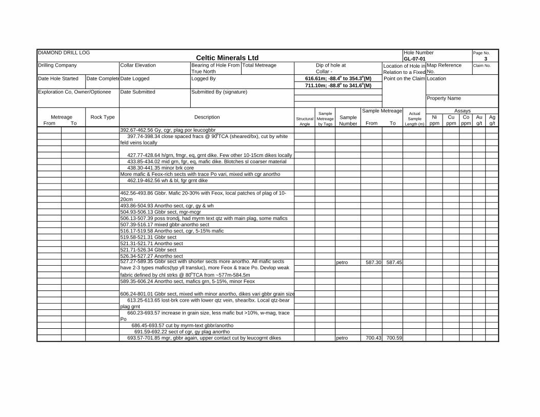
5.2 Results GL‐07‐01 was drilling between August 12th and September 3rd, 2007 to a final depth of 801.01m. The target for this hole was an MT geophysical Anomaly as outlined above. The drill hole cut Leucogabbro to anorthosite for its entire length, with the exception of several minor mafic dikes (Figure 11). The anorthosite present in the drill core contains high levels of magnetite; It has been determined that it is the magnetite contained in the anorthosite that was the cause of the MT anomaly and not a sulphide body as was previously hoped. Despite probing by downhole UTEM, no offhole conductors were defined. Given the results of GL‐07‐01, plans to drill hole GL‐07‐02 were abandoned and the program was considered complete.
5.3 Recommendations and Future Plans At this time, Celtic Minerals has not planned any follow up programs for the Garland Lake Property and no recommendations are made for future work.

589000
mE
589000
mE
589000
mE
589000
mE
589000
mE
589000
mE
589000
mE
589000
mE
589000
mE
588000
mE
588000
mE
588000
mE
588000
mE
588000
mE
588000
mE
588000
mE
588000
mE
588000
mE
587000
mE
587000
mE
587000
mE
587000
mE
587000
mE
587000
mE
587000
mE
587000
mE
587000
mE
586000
mE
586000
mE
586000
mE
586000
mE
586000
mE
586000
mE
586000
mE
586000
mE
586000
mE
584000
mE
584000
mE
584000
mE
584000
mE
584000
mE
584000
mE
584000
mE
584000
mE
584000
mE
585000
mE
585000
mE
585000
mE
585000
mE
585000
mE
585000
mE
585000
mE
585000
mE
585000
mE
580000
mE
580000
mE
580000
mE
580000
mE
580000
mE
580000
mE
580000
mE
580000
mE
580000
mE
578000
mE
578000
mE
578000
mE
578000
mE
578000
mE
578000
mE
578000
mE
578000
mE
578000
mE
579000
mE
579000
mE
579000
mE
579000
mE
579000
mE
579000
mE
579000
mE
579000
mE
579000
mE
6209000 mN6209000 mN6209000 mN6209000 mN6209000 mN6209000 mN6209000 mN6209000 mN6209000 mN
6210000 mN6210000 mN6210000 mN6210000 mN6210000 mN6210000 mN6210000 mN6210000 mN6210000 mN
6204000 mN6204000 mN6204000 mN6204000 mN6204000 mN6204000 mN6204000 mN6204000 mN6204000 mN
6205000 mN6205000 mN6205000 mN6205000 mN6205000 mN6205000 mN6205000 mN6205000 mN6205000 mN
6206000 mN6206000 mN6206000 mN6206000 mN6206000 mN6206000 mN6206000 mN6206000 mN6206000 mN
6207000 mN6207000 mN6207000 mN6207000 mN6207000 mN6207000 mN6207000 mN6207000 mN6207000 mN
6208000 mN6208000 mN6208000 mN6208000 mN6208000 mN6208000 mN6208000 mN6208000 mN6208000 mN
583000
mE
583000
mE
583000
mE
583000
mE
583000
mE
583000
mE
583000
mE
583000
mE
583000
mE
581000
mE
581000
mE
581000
mE
581000
mE
581000
mE
581000
mE
581000
mE
581000
mE
581000
mE
582000
mE
582000
mE
582000
mE
582000
mE
582000
mE
582000
mE
582000
mE
582000
mE
582000
mE
6203000 mN6203000 mN6203000 mN6203000 mN6203000 mN6203000 mN6203000 mN6203000 mN6203000 mN
.................................................CCCCCCCCCCCCCCCCCCCCCCCCCCCCCCCCCCCCCCCCCCCCCCCCC
CCCCCCCCCCCCCCCCCCCCCCCCCCCCCCCCCCCCCCCCCCCCCCCCC.................................................
Scale: 1:50,000
NAD 27 - Zone 20
Figure: 8
NTS: 14C/04
Celtic Minerals Ltd.GARLAND LAKE PROPERTY
Celtic Minerals Claims
Proposed DDH Location Map
-2.5
Kilometres
0 2.5 5
CCCCCCCCCCCCCCCCCCCCCCCCCCCCCCCCCCCCCCCCCCCCCCCCC .................................................Water Source Proposed Diamond Drill Hole
GL-2007-01581500mE, 6207250N
800m Depth GL-2007-02582000mE, 6206750N
700m Depth

ELEV
ATI
ON
10000
7500
5000
2500
1000
500
250
150
100
50
0Resistivity(ohm-m)
Scale: 1:15,000
NAD 27 - Zone 20
Figure: 9
NTS: 13N/13
Celtic Minerals Ltd.
GL-2007-01 Cross SectionLine 581500 2D MT Inversion
-500
Meters
0 500 1000 1500
6207
500 mN
6208
000 mN
6208
500 mN
‐1000 m
‐500 m
0 m
500 m
6206
500 mN
6206
000 mN
6207
000 mN
.

ELEV
ATI
ON
10000
7500
5000
2500
1000
500
250
150
100
50
0Resistivity(ohm-m)
Scale: 1:15,000
NAD 27 - Zone 20
Figure: 10
NTS: 14D/08
Celtic Minerals Ltd.-500
Meters
0 500 1000 1500
.
6208
000 mN
6208
500 mN
500 m
‐1000 m
‐500 m
0 m
6206
000 mN
6206
500 mN
6207
000 mN
6207
500 mN
GL-2007-02 Cross SectionLine 582000 2D MT Inversion

ELEV
ATI
ON
Scale: 1:15,000
NAD 27 - Zone 20
Figure: 11
NTS: 13N/13
Celtic Minerals Ltd.
GL-07-01 Cross Section
-500
Meters
0 500 1000 1500
6207
500 mN
6208
000 mN
6208
500 mN
6209
000 mN
‐1000 m
‐500 m
0 m
500 m
6206
500 mN
6206
000 mN
6207
000 mN
.
Leucogabbro to Anorthosite Mafic Dike

Garland Lake Property Celtic Minerals Ltd. 3rd Year Assessment
5.4 List of Expenditures
GARLAND LAKE ‐ LICENCE 10971M
EXPENSE AMOUNT
Borehole UTEM Survey $ 24,491.09 Building Supplies $ 517.72 Camp Rental $ 13,656.79 Camp Set‐up $ 2,508.00 Courier/Shipping Costs $ 6.04 Diesel $ 7,182.62 Direct Drilling Costs $ 166,157.93 Equipment Rentals $ 412.00 Field Supplies $ 629.75 Gasoline $ 549.99 Groceries and Dry Goods $ 6,709.87 Helicopter $ 173,266.15 Hotels and Meals $ 1,019.87 Jet Fuel $ 22,816.34 Logistics $ 1,171.89 Mob/Demob Charges $ 6,000.00 Propane and Tanks $ 194.37 Report Drafting and Digitizing $ 2,131.81 Safety Equipment $ 385.44 Salary ‐ Camp Cooks $ 7,970.00 Salary ‐ Camp Manager $ 5,525.67 Salary ‐ Geologist $ 5,575.54 Salary ‐ Labour/Drill Helper $ 1,750.00 Sample Assays $ 59.36 Satellite Communication and Internet $ 3,064.89 Transportation/Airfare $ 13,403.23
Subtotal $ 450,688.24
Administration fees (15%) $ 67,603.24
TOTAL $ 518,291.48

Garland Lake Property Celtic Minerals Ltd. 3rd Year Assessment
6.0 REFERENCES Amelin, Y, Li, C. and Naldrett, A.J., 1999: Geochronology of the Voisey’s Bay Intrusion, Labrador, Canada, by precise U‐Pb dating of
coexisting baddeleyite, zircon, and apatite. Lithos, volume 47, p. 33‐51.
Amelin, Y, Li, C. and Naldrett, A.J., 1997: Multistage Evolution of the Voisey’s Bay Complex, Labrador, Canada, Revealed by U‐Pb Systematics of Zircon, Baddeleyite, and Apatite. In Abstracts, AGU 1997 Fall Meeting.
Beesley, T.J. and Woolham, R.W., 1997: First year assessment report on geological, geochemical and geophysical exploration for licences 2526M‐2527M, 2828M‐2830M, 3082M and 3085M on claims in the Notakwanon River area, south‐central Labrador, 5 reports. Unpublished assessment report produced for Cartaway Resources Corporation, Cartaway Container Corporation and Freeport Resources Incorporated, 134 pages. Newfoundland and Labrador Geological Survey, Assessment File LAB/1218.
Bertrand, J.M., Roddick, J.C., Van Kranendonk, M., and Ermanovics, I.F., 1993: U‐Pb geochronology of deformation and
metamorphism across a central transect of the Early Proterozoic Torngat Orogen, North River map area, Labrador.. Canadian Journal of Earth Sciences, Volume. 30, p. 1470‐1489.
Burns, T.E., Barbour, D., Dearin, C. and de Carle, R.J., 1996: First year assessment report on geological, geochemical and geophysical exploration for licence 1146M on claims in the Side Brook area, northern Labrador, 2 reports. Unpublished assessment report produced for NDT Ventures Limited, Aranlee Resources Limited, Newfoundland Mining and Exploration Limited and Newminex, 71 pages. Newfoundland and Labrador Geological Survey, Assessment File LAB/1190.
Burns, T.E., Barbour, D., Dearin, C. and de Carle, R.J., 1996: First year assessment report on geological, geochemical and geophysical exploration for licence 1461M on claims in the Notakwanon River area, northern Labrador, 2 reports. Unpublished assessment report produced for NDT Ventures Limited, Layfield Resources Incorporated and Barry, L., 97 pages. Newfoundland and Labrador Geological Survey, Assessment File LAB/1189.
Chapman, J and van Damme, V., 1995: First year assessment report on geological and geochemical exploration for licence 2865m on claims in the area south of Side Brook, northern Labrador. Unpublished assessment report produced for New Claymore Resources Limited and Troymin Resources Ltd., Newfoundland and Labrador Geological Survey, Assessment File 14C/04/0075, 29 pages.
Clarke, E.J., 1997: Geological and Prospecting Report, Licence 2527M, (FP‐C), Notakwanon River South, NTS 14 C/4. Second year assessment report. Unpublished assessment report produced for Cartaway Resources Corporation, 9 pages plus Appendices. Newfoundland and Labrador Geological Survey, Assessment File 014C/04/0096.
Davenport, P.H., Nolan, L.W., Wardle, R.W., Stapleton, G.J. and Kilfoil, G.J., 1999: Geoscience Atlas of Labrador. Government of Newfoundland and Labrador, Department of Mines and Energy, Geological Survey Open File LAB/1305, version 1.0.
Emslie, R.F., 1980: Geology and petrology of the Harp Lake Complex, central Labrador; an example of Elsonian magmatism.
Geological Survey of Canada Bulletin 293, 136 p. Emslie, R.F., Hamilton, M.A., and Thériault, R.J., 1994: Petrogenesis of a mid‐Proterozoic anorthosite‐mangerite‐charnockite‐granite
(AMGC) complex: Isotopic and chemical evidence from the Nain Plutonic Suite. Journal of Geology, Volume 102, p.539‐558.
Evans‐Lamswood, D.M., Butt, D.P., Jackson, R.S., Lee, D/.V., Muggridge, M.G., and Wheeler, R.I., 2000: Physical Controls Associated with the Distribution of Sulfides in the Voisey’s Bay Ni‐Cu‐Co Deposit, Labrador. Economic Geology, Volume 95, p. 749‐769.
Friske, P.B.W., McCurdy, M.W., Day, S.J., Gross, H., Lynch, J.J. and Durham, C.C., 1993: National Geochemical Reconnaissance lake sediment and water data, northern Labrador (NTS 14C and parts of 14D and 24A). Geological Survey of Canada, Open File 2690.
Grosl, V and Rickli, M, 1995: First year assessment report on geological and geochemical exploration for licences 899m‐900m and 905m‐907m on claims in the Tasialuk Lake, Merrifield Bay, Flowers Bay and Sango Bay areas, Labrador. Unpublished assessment report produced by Cominco Limited, Newfoundland and Labrador Geological Survey, Assessment File LAB/1145, 1995, 52 pages.

Garland Lake Property Celtic Minerals Ltd. 3rd Year Assessment
Hattie, D, Muggridge, M, Lines, A, Cole, D J and Spurvey, P., 1997: First year assessment report on geological, geochemical and geophysical exploration for licences 3725m‐3726m, 3732m, 3737m‐3741m and 4113m on claims in the Alliger Lake, Konrad Brook, Anaktalik Lake, Tasisuak Lake and Tasialuk Lake areas, Labrador. (9 reports) Unpublished assessment report produced for Westpine Metals Limited, Newfoundland and Labrador Geological Survey, Assessment File LAB/1225, 1997, 113 pages.
Hill, J. D., 1982: Geology of the Flowers River – Notakwanon River Area, Labrador. St. John’s Newfoundland Department of Mines and Energy, Geological Survey Branch Report 82‐6. 140 pages.
Krogh, T.E. and Heaman, L.M., 1989: Report on U‐Pb results for the 1988/89 Labrador geochronology contract: St. John’s Newfoundland Department of Mines and Energy, Geological Survey Branch, unpublished report.
Lee, D, 2004: An overview of the Voisey's Bay Project and its future development. Verbal Presentation, Newfoundland Branch, Geological Association of Canada Annual Technical Meeting, February 23rd and 24th, 2004.
MacGillivray, G., 1996: First year assessment report on geological, geochemical, geophysical and diamond drilling exploration for licences 760M‐761M, 765M, 790M‐792M, 820M‐822M, 834M‐837M, 843M, 855M, 867M, 886M‐888M, 896M‐898M, 916M‐919M, 933M‐938M, 941M‐943M, 956M, 980M, 1022M, 1026M, 1071M, 1091M‐1093M, 1098M‐1104M, 1118M, 1132M‐1140M, 1149M, 1151M‐1154M and 4152M on claims in the Tasisuak Lake, Kogaluk River, Throat Bay, Anaktalik Brook, Iglusuataliksuak Lake and Kikkertavak Island areas, Labrador, 3 reports. Unpublished assessment report produced for Absolut Resources Corporation, 383 pages. Newfoundland and Labrador Geological Survey, Assessment File LAB/1156.
Moore, P. and Hussey, A. 2006: 1st year assessment Report on Geological Mapping, Prospecting & Lithogeochemical Sampling on
the Garland Property, Labrador. Licences 10970M, 10971M & 11257M. Unpublished assessment report produced for Cornerstone Resources Inc., 33 pages.
Morrison, G.C., 2001: Assessment report of exploration activities (geological and geophysical) on mineral licences 7654M, 7655M,
7656M, & 7657M, NTS 14C/4, Garland Lake project Labrador. Unpublished assessment report produced for Inco Technical Services Limited, 17 pages plus appendices. Newfoundland and Labrador Department of Mines and Energy assessment file number LAB/1406.
Naldrett, A.J., Keats, H., Sparkes, K., and Moore, R., 1996: Geology of the Voisey’s Bay Ni‐Cu‐C0 Deposit, Labrador, Canada. Exploration and Mining Geology (Canadian Institute of Mining, Metallurgy, and Petroleum), Volume 5, Number 2, p. 169‐179.
Nichols, L., and Nikols, D., 1998: Third year assessment report on geological exploration for licence 5584M on claims in the
Notakwanon River area, central Labrador. Unpublished assessment report produced for Freeport Resources Incorporated. Newfoundland and Labrador Geological Survey, Assessment File 13N/13/0120, 14 pages.
Ryan, B., 2003: Two, Spatially Coincident but Temporally Disparate, Proterozoic Anorogenic‐type Granitic (and Anorthositic) Suites in Northern Labrador, Canada. Abstract, Helsinki.
Ryan, B., 2000: The Nain‐Churchill Boundary and the Nain Plutonic Suite: a regional perspective on the geologic setting of the Voisey’s Bay Ni‐Cu‐Co deposit. Economic Geology, Volume 95, p. 703‐724.
Ryan, B., 1997: The Mesoproterozoic Nain Plutonic Suite in Eastern Canada, and the setting of the Voisey’s Bay Ni‐Cu‐Co sulphide deposit. Geoscience Canada, Volume 24, Number 4, p. 173‐188.
Ryan, B., 1996: Commentary on the location of the Nain‐Churchill boundary of the Nain area. Current Research, Report 96‐1, Geological Survey, Department of Natural Resources, Government of Newfoundland and Labrador, p. 109‐129.
Ryan, B. (compiler), 1990: Preliminary geological map of the Nain Plutonic Suite and surrounding rocks (Nain‐Nutak, NTS 14 SW.), scale 1:500,000. Geological Survey Branch, Department of Mines and Energy, St. John’s, Newfoundland, Map 90‐44.
Ryan. B and Kerr, A., 2005: A Review of Bedrock and Economic Geology of Northern Labrador. In A Workshop on the Mineral Resources in Greenland and Eastern North America, Abstract Volume, Geological Survey of Denmark and Greenland, Copenhagen, p. 11‐16.

Garland Lake Property Celtic Minerals Ltd. 3rd Year Assessment
Ryan, B., Hamilton, M.A., Emslie, R.F and Connelly, J.N., 2003: Two, spatially coincident but temporally disparate, Paleoproterozoic anorogenic‐type granitic (and anorthositic) suites in northern Labrador, Canada. In Granitic Systems ‐ State of the Art and Future Avenues: an international symposium in honor of Professor Ilmari Haapala, Abstract Volume (Edited by O.T. Rämö, P.J. Kosunen, L.S. Lauri and J. A. Kahru), Helsinki University Press, p. 79‐83.
Ryan, B., Phillips, E., Shwetz, J., and Machado, G., 1998: A tale of more than ten plutons [Geology of the region between Garland Bay and Staghorn Lake, Labrador (Parts of NTS Maps 14E/2, 7, 8)]. Current Research, Report 98‐1, Geological Survey, Department of Natural Resources, Government of Newfoundland and Labrador, p. 143‐171.
Ryan, B., Wardle, R., Gower, C. and Nunn, G., 1995: Nickel‐Copper Sulphide Mineralization in Labrador, The Voisey Bay Discovery and its exploration implications. In: Current Research, Report 95‐1, Geological Survey, Department of Natural Resources, Government of Newfoundland and Labrador, p. 177‐204.
Ryan, B., Krogh, T.E., Heaman, L., Scharer, U., Philippe, S. and Oliver, G., 1991: On recent geochronological studies in the Nain Province, Churchill Province and Nain Plutonic Suite, north‐central Labrador. In: Current research, Newfoundland and Labrador Geological Survey Report 91‐1, p. 257‐261.
Ryan, A. B. and Lee, D., 1986: Gneiss‐anorthosite‐granite relationships in the Anaktalik Brook Kogaluk River area (NTS 14D/1,8), Labrador. In: Current Research, Newfoundland and Labrador Department of Mines and Energy, Mineral Development Division, Report 86‐1, pages 79‐88.
Taylor, F.C., 1977: Geology, Nain, Newfoundland. Geological Survey of Canada, "A" Series Map , 1437A, 1:250,000.
Wardle, R.J., Swinden, S. and James, D.T., 1995: The Southeastern Churchill Province. In: The Geology and Mineral Deposits of Labrador: A Guide for the Exploration Geologist (compiled by R.J. Wardle). Workshop handout, Geological Survey, Newfoundland Department of Natural Resources.
Wardle, R.J. (compiler), 1993: Geology of the Naskaupi River region, central Labrador (13NW), scale 1:500,000. Geological Survey Branch, Department of Mines and Energy, St. John’s, Newfoundland, Map 93‐16.
Wardle, R.J., Ryan, B., Nunn, G.A., and Mengel, F., 1990: Labrador Segment of the Trans‐Hudson orogen: Crustal development through oblique convergence and collision. Geological Association of Canada Special Paper 37, p. 353‐369.
Wares, R., Leriche, P.D. and Woolham, R.W., 1995: First year assessment report on geological, geochemical and geophysical exploration for licences 940M, 1044M‐1055M and 1194M on claims in the Kogaluk River area, northern Labrador, 2 reports. Unpublished assessment report produced for United Compass Resources Limited, Layfield Resources Incorporated, Newfoundland Mining and Exploration Limited, Patey, D., Wells, P., Patey, G., Graham, R., Graham, B., Janes, S., Comerford, D., Goosney, D., Anderson, T.C., Anderson, D., Tooton, A.G. and Tooton, J., 105 pages. Newfoundland and Labrador Geological Survey, Assessment File LAB/1221.

Garland Lake Property Celtic Minerals Ltd. 3rd Year Assessment
APPENDIX 1 Diamond Drill Logs

DIAMOND DRILL LOG Hole Number Page No.
Drilling Company Collar Elevation Total Metreage Map Reference Claim No.801.01 No.
Date Hole Started Date CompleteDate Logged Logged By Location2007-09-03 581478E NAD
Exploration Co, Owner/Optionee Date Submitted Submitted By (signature) 6207247N 27581531E NAD6207475N 83
Rock Type Ni Cu Co Au AgFrom To From To ppm ppm ppm g/t g/t
0.00 0.35 OVB
0.35 Leucogabbro to anorthosite
PAUL DELANEY
99.04-119.68 gy, n-mag, mcgr-cgr & local vcgr leucgbbr to anortho. Plag w schill. Fracs have talcy feel, very soft, mafic mid grn, trace Po, mafics patchy
0.35-18.60 1.0m of BW core. Gy & wh, n-mag, mcgr, Ol? Gbbr. Very patchy w white-rim, gy core plag-rich zones & mid ggy, more mafic w gy plag. Mafics vari 15-25%-lt&dk grn, trans yell + bt. Ol? Conc/only in more mafic blotches. Few % Ilm. Trace Po assoc w mafic
18.60-23.19 Gy, mcgr, n-mag, bit finer?, not blched, same compo,gy plag
50.39-50.56 seam, lost core
51.68-54.25 dk gy/purp vcgr plag-rich sect 54.25-73.73 mottled (wh matrix, gy plag xtls) w local, common bx-like text. Sporad zones of mafic conc (yll, trans type). Local zones of 99% gy/purp plag , minor mafic, some Po on fracs of <1mm. Trace -minor Po+/-Cp assoc w mafics & local coarser splashes(54.66-54.87 w Cp)
73.73-77.74 grnish, mgr, wkly feld phy, more mafic (yll&gy, 25-30%) gbbr dike. Upper contact sharp @ 45oTCA, lower less sharp, irreg.
79.08-82.09 gy/purp w wh matrix, bx-like text, interstit mafic (gy-yll) as above 82.09-83.38 dike as above, some qtz on borders, contacts irreg, some brk core
Major DrillingDip of hole atCollar - -90
67.97m; -88.6o to 338.3o(M)
Location of Hole in Relation to a Fixed Point on the Claim
Bearing of Hole From True North
Celtic Minerals Ltd GL-07-01
Metreage Description
Celtic Minerals/Cornerstone
Garland Lake South
Garland Lake
Structural Angle
Sample Metreage by Tags
243.23m; -88.7o to 340.9o(M)
104.55m; -88.5o to 348.8o(M)2007-08-12
1
14C/04 10971M
Property Name
Actual Sample
Length (m)Sample Number
Sample Metreage
151.79m; -88.7o to 335.7o(M)195.99m; -88.7o to 338.6o(M)
Assays
Overburden
109.12-109.39 & 110.04-110.74 brk coer, talcy, 0 oTCA
98.24-99.04 brk core, bx, lch & ox, pug - fault
89.49-89.82 mrym-text grnt dike
23.19-51.68 same as top section. 15% mafics, with Feox interstit to plag. Plag local has schill and flow text
89.82-91.08 main gbbr 91.08-91.68 grnt dike+/-myrm 97.50 brk core, cy, blch
105.51 3cm grnt dike @ 45 oTCA
77.74-79.08 var bx-leach zone w grnt
83.38-89.49 main gbbr, rare cgr grnt pod

DIAMOND DRILL LOG Hole Number Page No.
Drilling Company Collar Elevation Total Metreage Map Reference Claim No.No.
Date Hole Started Date CompleteDate Logged Logged By Location
Exploration Co, Owner/Optionee Date Submitted Submitted By (signature)
Rock Type Ni Cu Co Au AgFrom To From To ppm ppm ppm g/t g/t
petro 202.16 202.30
petro 206.65 206.75
Mafic Dike
127.57-127.91 starts ox-sil alt, grnt dikes
274.83-276.27 brk core & grnt material
Minor grnt dike/pods past mafic dikes, some graph textCont as blotchy, gy/wh, leucgbbr w 2 or 3 mafic mins
202.11-202.30 grn, fmgr, n-mag, gbbr dike/xeno? More mafic 2% doiss Po & two Po stringers on fracs. Upper cntct diffuse, lower sharp 206.57-206.75 grn, fgr, n-mag, gbbr dike/xeno. Quite mafic, sharp contacts, mafic yll-trans
363.94- 376.40 gy & patchy wh, cgr leucogbbr
349.97-363.94 mid gy, fgr-fmgr, eq, n-mag dibs dike. Looks like late dike. Upper contact brk w cal v, lower sharp
314.04-314.20 & 316.29-316.60 b&w, fgr grnt dikes 336.62-337.32 brk core, then fgr, aplt dike @ 336.74-337.32 337.32-338.05 2cm qtz vein at contact & veins & xeno
390.80-392.67 grnt dike vari shear & healed bx w large part of gbbr/anortho, contacts sharp & sil alt & brk core at lower
163.30-172.69 Fault Zone-bx, sil alt/veins, leach, hem/ox
172.69-349.97 Gy, cgr, n-mag, anortho-gbbr, minor Po. Mafics grn pyx/hbl+btMinor leucogrnt dikes of 2-3cm @ vari angle TCA @ 185.00-191.09
261.67-263.10 w&b, fgr grnt dike @30oTCA
344.46-344.62 brk core, cal v
376.40-390.80 gy, more anorho sect, w zones more mafic %
348.09-349.97 50% cal v & brk core
Seems more anorthositic below Frac Zone
128.75-151.85 Fractured Zone - vari ox, sil alt & veined, bx, epi alt, leach of main host
115.09-115.26 fault bx, pug. Vari ox below
AssaysSample Metreage by Tags
Sample Number
525.17m; -88.6o to 331.2o(M)
119.68-120.75 buff, fgr* peg grnt dike 122.28-124.36 bx, brk core, ox rock
Structural Angle
Sample Metreage Actual Sample
Length (m)
Property Name
339.24m; -88.7o to 356.3o(M)384.96m; -88.4o to 333.6o(M)
430.68m; -88.0o to 178.7o(M)??
Metreage Description
Collar - 293.52m; -88.7o to 356.4o(M)
2Location of Hole in Relation to a Fixed Point on the Claim
Bearing of Hole From True North
Dip of hole atCeltic Minerals Ltd GL-07-01
DIAMOND DRILL LOG Hole Number Page No.
Drilling Company Collar Elevation Total Metreage Map Reference Claim No.No.
Date Hole Started Date CompleteDate Logged Logged By Location
Exploration Co, Owner/Optionee Date Submitted Submitted By (signature)
Rock Type Ni Cu Co Au AgFrom To From To ppm ppm ppm g/t g/t
petro 587.30 587.45
petro 700.43 700.59
606.24-801.01 Gbbr sect, mixed with minor anortho, dikes vari gbbr grain size 613.25-613.65 lost-brk core with lower qtz vein, shear/bx. Local qtz-bear plag grnt 660.23-693.57 increase in grain size, less mafic but >10%, w-mag, trace Po
507.39-516.17 mixed gbbr-anortho sect516.17-519.58 Anortho sect, cgr, 5-15% mafic
691.59-692.22 sect of cgr, gy plag anortho 693.57-701.85 mgr, gbbr again, upper contact cut by leucogrnt dikes
521.31-521.71 Anortho sect521.71-526.34 Gbbr sect526.34-527.27 Anortho sect
589.35-606.24 Anortho sect, mafics grn, 5-15%, minor Feox
686.45-693.57 cut by myrm-text gbbr/anortho
527.27-589.35 Gbbr sect with shorter sects more anortho. All mafic sects have 2-3 types mafics(typ yll transluc), more Feox & trace Po. Devlop weak fabric defined by chl strks @ 80oTCA from ~577m-584.5m
519.58-521.31 Gbbr sect
433.85-434.02 mid grn, fgr, eq, mafic dike. Blotches sl coarser material 438.30-441.35 minor brk coreMore mafic & Feox-rich sects with trace Po vari, mixed with cgr anortho 462.19-462.56 wh & bl, fgr grnt dike
493.86-504.93 Anortho sect, cgr, gy & wh504.93-506.13 Gbbr sect, mgr-mcgr
462.56-493.86 Gbbr. Mafic 20-30% with Feox, local patches of plag of 10-20cm
506.13-507.39 poss trondj, had myrm text qtz with main plag, some mafics
Metreage Description Sample Number
Property Name
AssaysActual Sample
Length (m)Structural
Angle
Sample Metreage by Tags
Sample Metreage
711.10m; -88.8o to 341.6o(M)
GL-07-01 3Location of Hole in Relation to a Fixed Point on the Claim
Bearing of Hole From True North
Dip of hole atCollar -
616.61m; -88.4o to 354.3o(M)
397.74-398.34 close spaced fracs @ 90oTCA (sheared/bx), cut by white feld veins locally
427.77-428.64 h/grn, fmgr, eq, grnt dike. Few other 10-15cm dikes locally
392.67-462.56 Gy, cgr, plag por leucogbbr
Celtic Minerals Ltd

DIAMOND DRILL LOG Hole Number Page No.
Drilling Company Collar Elevation Total Metreage Map Reference Claim No.No.
Date Hole Started Date CompleteDate Logged Logged By Location
Exploration Co, Owner/Optionee Date Submitted Submitted By (signature)
Rock Type Ni Cu Co Au AgFrom To From To ppm ppm ppm g/t g/t
petro 758.17 758.29
petro 800.89 800.99 771.97-775.97 Anortho-gbbr(leuco), cgr
EOH
775.97-801.01 Gbbr, mgr, local larger plag xtl, w-m mag, common flow text in gbbr
4
701.85-714.85 cgr anortho to leucogbbr sect, trace Po, matrix vari wh-gy
AssaysStructural
Angle
Sample Metreage by Tags
Sample Metreage Actual Sample
Length (m)
Property Name
750.45-771.97 Gbbr, mgr
Celtic Minerals Ltd
727.71 brk core 730.52 minor brk core
714.85-743.91 gbbr, mgr, minor cgr patches, plag blch whiter, more than above sects due to frac zone, vw-mag, trace Po, lots prob ilm
743.91-750.45 cgr, less mafic anortho/leucogbbr. Feld blch & wk seri or yll epi 746.29-747.78 mgr, mafic sect, gbbr
Location of Hole in Relation to a Fixed Point on the Claim
Bearing of Hole From True North
Dip of hole atCollar -
Metreage Description Sample Number
Garland Lake Property Celtic Minerals Ltd. 3rd Year Assessment
APPENDIX 2 Borehole UTEM Preliminary Report

Logistics Report on a BH UTEM 4 Surveyin
Garland Lake, Labradorfor
Celtic Minerals Ltd.
Garland Lake Holes: GL-07-01
LAMONTAGNE GEOPHYSICS LTDGEOPHYSIQUE LTEE
January 2008Brayden McNeill
Geoff Heminsley, P. Geo

INTRODUCTION
A BH UTEM 4 Survey was conducted by Lamontagne Geophysics Ltd. personnel for Celtic Minerals beginning on November 1st, 2007 and ending on November 14th, 2007. One hole was surveyed in the Garland Lake area (Figure 1). The purpose of the survey was to locate and define any conductors present or in the vicinity of the boreholes.
This report documents all survey logistics. Results, presented as BH UTEM 4 profiles and vector plots, are attached as appendices.
SURVEY DESIGN
At Garland Lake, one hole was surveyed. Hole GL-07-01 was surveyed using Loop 1. Hole GL-07-01 was surveyed at a frequency of 30.974 Hz.
For the above BH UTEM 4 coverage, measurements of the axial (Hw) and the two transverse (Hs and Hn) components of the electromagnetic field were taken. Also, three component magnetometer and three component accelerometer and temperature data were collected. The nominal station spacings were forty metres for the top portion of the hole. The spacings were decreased to ten or twenty metres for the bottom portion of the hole and further to five metres if it was thought necessary to better define an anomalous zone. At every station, thirteen channel data were collected with a minimum stack of 512 half cycles recorded at every station. Repeat readings were taken regularly to ensure the repeatability of the data.
For additional information on aspects of BH UTEM 4 survey design and the Data Presentation and Reduction schemes used during this survey, see Appendix A.
Celtic Minerals Ltd. - BH UTEM 4 Survey - Garland Lake, Labrador - 0737 - Page 1

LAMONTAGNE GEOPHYSICS LTDGEOPHYSIQUE LTEE
0 200 400 600 800 1000 meters
1 : 20 000
Celtic Minerals Ltd. - BH UTEM 4 Survey - Garland Lake, Labrador - 0737 - Page 2
Celtic Minerals Ltd.Area Location Map
Garland Lake, LabradorFigure 1

Field Work
The Lamontagne Geophysics crew began operations on November 1st, 2007 and continued to November 14th, 2007. The crew consisted of G. Lafortune and A. George. Operations were based out of the Astanik Lodge in Nain, Labrador.
Various survey equipment was used throughout the project, including UTEM 3 transmitters, UTEM 4 receivers, BH UTEM 4 probes, borehole winch system, fiber optic cables and all accessories and support equipment. A field computer (iMac) was used for all reduction and plotting of the survey data while on site. The data was delivered to Celtic Minerals on a timely basis.
A description of the daily field work is provided in the Production Log that follows. All production is summarized in Table 1. Site specific details of all data acquisition activities are provided below. Geometric control for all transmitter loops were achieved with a hand-held GPS system.
Garland Lake: Hole GL-07-01 was surveyed using Loop 1 (Figure 2) on November 13th. Hole GL-07-01 was surveyed to 790m and was dummied to 798m.
Celtic Minerals Ltd. - BH UTEM 4 Survey - Garland Lake, Labrador - 0737 - Page 3

LAMONTAGNE GEOPHYSICS LTDGEOPHYSIQUE LTEE
Celtic Minerals Ltd.
Figure 2
Celtic Minerals Ltd. - BH UTEM 4 Survey - Garland Lake, Labrador - 0737 - Page 4
BH UTEM 4 Survey - Loop Location Map Garland Lake, Labrador
Figure 21 : 20,000
0 200 400 600 800 1000 meters
Location of Hole GL-07-01
Loop 1GL-07-01

Production Log (0737)Celtic Minerals Ltd.
Date Rate Production Comments
Nov 1 Mob - The BH UTEM 4 equipment is shiped in two shipments, one from Sudbury and one from Kingston.
Nov 5 Mob - G. Lafortune and A. George travel from home to Goose Bay. Luggage with personal clothing was lost by Air Jazz.
Crew: G. Lafortune and A. George.
Nov 6 S-2 - G. Lafortune and A. George travel from Goose Bay to Nain. Personal gear still missing.
Most of the UTEM equipment is in Nain, the probes are still in Goose Bay. The wire was picked up from the Pants Lake camp (a UTEM crew working for another client in the area) and brought back to Nain.
Crew: G. Lafortune and A. George.
Nov 7 S-2 - Standby due to weather in Nain.Crew: G. Lafortune and A. George.
Nov 8 L-2 - Arrived at survey location. Located the hole and started laying wire. The helicopter returned to Nain to bring out the survey equipment. When the helicopter returned the crew returned to Nain also due to being wet. Snow conditions were very bad on the grid, one crew member had fallen into a crevice up to his armpits, snowshoes were needed.
Crew: G. Lafortune and A. George.
Nov 9 S-2 - The weather did not look very promising but the pilot thought it may be okay. Went to a nearby camp to pickup snowshoes on the way the helicopter started picking up ice we returned to Nain and waited to see if the weather would lift which it did not.
Crew: G. Lafortune and A. George.
Nov 10 S-2 - The weather was looking okay but there was snow in the air. Arrived at survey site. The operator was setting up to dummy the hole and the second crew member was looping. The helicopter was parked close to the hole. After an hour the pilot was concerned about the weather which was closing in so we returned to Nain. One side of Loop was laid. The hole was not dummied.
Crew: G. Lafortune and A. George. Celtic Minerals Ltd. - BH UTEM 4 Survey - Garland Lake, Labrador - 0737 - Page 5

Date Rate Production Comments
Nov 11 L-2 - Dummied Hole GL-07-01 (798m) at Garland Lake. Finished laying Loop 1 which was very slow going due to
snow and terrain which is very rough.Crew: G. Lafortune and A. George.
Nov 12 D-2 - Read: Hole GL-07-01 Loop 1 790m 30.974 Hzat Garland Lake.
The data was found to be unacceptable, there was a problem with the receiver filters.
The transmitter generator which was gotten from AIVEL Holdings did not run due to lack of oil. Helicopter had to return to Nain for oil.
Crew: G. Lafortune and A. George.
Nov. 13 P-2 790m Read: Hole GL-07-01 Loop 1 790m 30.974 Hzat Garland Lake.
Picked up one side of Loop 1.Crew: G. Lafortune and A. George.
Nov 14 0.5 L-2 - Finished picking up Loop 1.The equipment was slung to another job in the area for
another client.Job complete.Crew: G. Lafortune and A. George.
---------------------------------------------------------------------------------------------------------------
LEGEND
P-x - Production - # of personnel L-x - Looping - # of personnelS-x - Stand By - # of personnel D-x - Down - # of personnel
Celtic Minerals Ltd. - BH UTEM 4 Survey - Garland Lake, Labrador - 0737 - Page 6

Table 1 - Survey Summary
Borehole Survey Dummy LoopProject Area Name Depth Depth Number Frequency
Garland Lake GL-07-01 790m 798m 1 30.974 Hz
Celtic Minerals Ltd. - BH UTEM 4 Survey - Garland Lake, Labrador - 0737 - Page 7
Appendix A
The BH UTEM 4 System
BH UTEM 4 SurveyGarland Lake, Labrador
forCeltic Minerals Ltd.

The BH UTEM 4 System
The BH UTEM 4 downhole system is a three axis downhole transient EM system which incorporates a low noise coincident three-axis coil design, fully digital down-the-hole encoding and a fibre optic probe-to-surface data link. The system allows three components of the transient magnetic field to be simultaneously averaged and stored. Probe orientation within the hole is monitored by integrated 3-axis magnetometer and 3-axis accelerometer devices. Temperature measurements taken to correct the accelerometer package can also be used to detect the thermal signature of ore bodies.
Waveform and Sampling
The UTEM transmitter passes a low-frequency (4 Hz to 90 Hz) current of a precisely regulated waveform through the transmitter loop. The frequency may be set to any value within the operating range of the transmitter, but is usually set at 31 Hz so as to minimize power line effects (60 Hz noise). Lower base frequencies are used to survey highly conductive bodies with time constants much larger than the 16 ms half-cycle.
Since the receiver coil responds to the time derivative of this magnetic field, it is said that the system really "sees" the step response of the ground. In practice, the transmitted waveform is tailored to optimize signal to noise and deconvolution techniques are employed within the system to produce an equivalent to this conceptual “step response” at the receiver. UTEM is the only time domain system which measures the step response of the ground. All other T.D.E.M. systems, to date, transmit a modified step current so that they "see" the (im)pulse response of the ground at the receiver.
While the channel time gates are programmable, a standard set of 13 time gates which fully sample the waveform are usually used as shown in Figure A2. The time gates are described with respect to a system of units in which the length of the half-cycle is 1062 units. Ten of the thirteen channels are plotted and used for standard interpretation. Figure A1 shows the plotting symbols used for these channels. The latest of these is designated as channel 1 and it occupies almost the entire second half of the half-cycle, from 512 -1024 units. Channels 2-10 are arranged in a binary progression, each occupying one half of the time interval remaining from the beginning of the half cycle. Thus channel 2 is from 256 to 512 units, channel 3 is from 128 to 256 units, etc. Channels 11 and 12 are only one unit wide (15 microseconds at 31 Hz) and they occupy opposite sides of the waveform transition. They are used primarily for the purposes of monitoring phase drift between the transmitter and receiver clocks. Channel 13 occupies the 37 unit wide interval from the end of channel 1, 1024 units, to 1061 units. While this is later than channel 1, this channel is much narrower and hence less precise. It is used in quality control and in some processing techniques, but is not usually displayed.
Appendix A - Celtic Minerals Ltd. - BH UTEM 4 Survey - Garland Lake, Labrador - 0737 - Page A1
UTEM System Mean Delay TimesUTEM System Mean Delay TimesUTEM System Mean Delay Times10 Channel Mode @ 31 hz.(approx.)10 Channel Mode @ 31 hz.(approx.)10 Channel Mode @ 31 hz.(approx.)
( base freq: 30.974 hertz )Delay
Channel time (ms) Plot Symbol1 12.112 6.0533 3.0274 1.5135 0.7576 0.3787 0.1898 0.0959 0.04710 0.024
Figure A1

Probe Orientation
Because the probe is rotating freely in the hole, the raw transverse components must be “rotated” to point in a consistent direction along the hole. The rotation process is mathematical and is performed after the data are collected, but it requires a knowledge of the actual orientation of the probe in the hole at each station. The determination of the probe orientation is achieved using two independent tools: a three-axis magnetometer and a 3-axis accelerometer. Data from these devices are collected before each EM stack. In ideal situations, such as an inclined hole directed well away from magnetic north and away from large magnetic anomalies, either tool is capable of precise orientation of the probe. In a near vertical hole, the accelerometer is incapable of determining the probe orientation, while in a hole directed along the Earth’s magnetic field, the same is true for the magnetometer. The data reduction software uses the best combination of the estimates derived by these two devices.
Coordinate Systems
The three observed components of the transient magnetic field are designated as Hu, Hv and Hw, with Hw being the axial component pointing down the hole and Hu and Hv oriented in a right-handed system with respect to Hw. The coordinate systems used to orient these transverse three-axis data are based on the concept of a drill section. The drill section is a vertical plane perpendicular to the geological strike and is, in general, the plane in which inclined holes would be drilled. The drill section azimuth specifies the azimuth of the positive coordinate direction within the plane. For a north-south section plane, for instance, the drill section azimuth would be zero, or due north, while for an east west section plane, it would be 90 or east. Usually, a section azimuth is adopted for an entire survey area, even if the actual azimuths of individual holes are slightly different. Once the direction is determined by the section azimuth, the out of section direction is 90 degrees clockwise from the section azimuth as seen in plan.
Appendix A - Celtic Minerals Ltd. - BH UTEM 4 Survey - Garland Lake, Labrador - 0737 - Page A2
1234
1234
6-11
3711312
11 10 9 8 7 6
1
1062
4 8 162
Figure A2. UTEM 4 13 channel sampling.

The UTEM 4 data are presented in one of two coordinate systems. The coordinate system used to express the data is identified by the notation used for the components.
Hole based coordinate system
This is the most commonly used system. In this system, the components are designated as Hs, Hn and Hw. Hw is the axial component and, as such, is independent of the orientation of the probe in the hole. Hs lies in the designated drill section plane while the Hn component is as near to the plane that is perpendicular to the section plane as possible, while also being perpendicular to the axial component. The coincidence of the Hn and the out-of-section plane will only be possible if the local hole azimuth is exactly the same as the designated section azimuth.
The hole based coordinate system is useful for a number of reasons. It is easiest to interpret the orientation of a conductive body relative to the trajectory of the hole, rather than in absolute terms. In this respect, a coordinate system that is hole-relative is much easier to use. A second important reason is that the axial component has a substantially higher signal/noise than the transverse components. In the hole based system, the axial component is plotted as is and is not required to be combined with the transverse components.
Cartesian System
Although it is not a standard presentation, it may be useful from time to time to present the data in Cartesian system. In this system the HS component is in the section direction, the HN component is in the out of section direction, and the HZ direction is down. In this system, except in a vertical hole, every component is a linear combination of the three raw observed components.
Figures A3 and A4 show the main features of the geometry conventions and terminology used. In Figure A3, the transient field vector is designated as H, which is resolved into the axial, Hw, and the transverse Htr components. The transverse Htr is resolved into the Hs and Hn components. The Hs lies in the plane of the drill section and Hn is perpendicular to both Hs and Hw and clockwise from Hs as seen in plan. Note that the drill hole itself does not lie in the drill section. Because of this, the Hn component will not be exactly in the out-of-section plane for this example. The drill section is specified by the section azimuth, measured clockwise from geographic north.
Figure A4 shows the relationship of the hole geometry to the magnetic and gravitational fields used for orienting the probe. The magnetometer and accelerometer are both resolved into axial (Aw, Mw) and transverse (Atr, Mtr) components. For each device, it is the resolution of the computed transverse field direction with the two observed transverse signals which determines the probe orientation. The precision of orientation is greatest when the transverse field is a large component of the total.
Appendix A - Celtic Minerals Ltd. - BH UTEM 4 Survey - Garland Lake, Labrador - 0737 - Page A3

Appendix A - Celtic Minerals Ltd. - BH UTEM 4 Survey - Garland Lake, Labrador - 0737 - Page A4
S
positive clockwise from geographical north
Hole
BH UTEM ORIENTED COMPONENTS Hw, Hs, Hn
Hs
Hn
Htr “drillsection”
Hw
H N(geogr.)
S azimuth
S azimuth
S to right of page N toward observer W axial down
STANDARD VIEW
Figure A3

Appendix A - Celtic Minerals Ltd. - BH UTEM 4 Survey - Garland Lake, Labrador - 0737 - Page A5
Nm
dm
Magn. incl.
Hole dipAtr
Aw
MtrMw
M
A
Hole az.
Hole az.
dm (magn. decl.)positive clockwise from geographical north
NRef. az.
Ref
Ref. azimuth
positive clockwise from Ref (reference direction)
Hole
Hole dip
Magn. incl. negative down from horizontal
}
}
HOLE GEOMETRY ANGLES
Figure A4

Orientation Device Selection
The factors which limit the precision of the magnetometer and accelerometer devices as orientation tools are itemized below.Magnetometer Accelerometermag anomalies gravitational anomalies insignificanterrors in magnetic declination and inclination orientation of gravitation field is known preciselyerrors in surveyed azimuth and dip of hole errors in surveyed azimuth and dip of holeno significant temperature dependence temperature calibration of accelerometer incorrectmag tensor calibration acc tensor calibration
While these factors cannot be tracked individually on a routine basis, the total transverse magnetic and gravitational fields are independent of the rotation of the probe in the hole and can be compared to their predicted values. The discrepancy between these is a measure of the “error” of the device as far as its use as an orientation tool. It forms a basis for the orientation tradeoff parameter, α.. This is a parameter that varies from +1.0 for pure magnetometer, to -1.0 for pure accelerometer. In between, a linear weighted average between the probe orientations as determined by the mag and accelerometer is used.
Data Reduction
The kind of reduction applied to the raw data is indicated on each plot in the second field of the title block. The observed UTEM data represents a sum of the signal directly from the transmitter loop (primary field) and the field resulting from eddy currents induced in conductive bodies and/or a conductive host rock (secondary field). In the case of a Total Field plot, the observed data are simply expressed as a percentage of a normalizing field that is either the primary field magnitude at a fixed point in space (point normalization) or the primary field magnitude at each station (continuous normalization). The Secondary Field is of most interest from an interpretive point of view. As such, an estimate of the primary field must be determined and subtracted from the data. There are two ways in which this is done:
(1) Primary Field Reduction - The computed primary field is subtracted from all channels. This is designated by the formula (Chn-Hpc)/(|Hp|) in the title block of the plot.
(2) Channel 1 Reduction - The computed primary field is subtracted from Channel 1. For all earlier channels, channel 1 is subtracted as an estimate of the primary field. This is designated by the formula (Chn-Ch1)/(|Hp|) in the title block of the plot.
As in the Total field case, the |Hp| primary field magnitude in the denominator is either evaluated at a fixed point in space (point normalization) or at each station (continuous normalization).
Standard BHUTEM 4 Plot Suite
The UTEM 4 3-axis data are usually presented as a set of five profile plots for each hole and loop surveyed. The data are plotted as a function of the distance down the hole. The depth axes are always labelled in metres but are also labelled in feet on imperial grids. Each axis which displays EM data indicates the component according to the conventions discussed above (Hs,Hn,Hw). As well, the component is indicated graphically by the direction of the arrow in the small coordinate axis system plotted at the end of each axis. To understand this system, consider that the plot is oriented with the axis down, that the section plane is the plane of the paper and that the section direction is to the right. The out of section component is then out of
Appendix A - Celtic Minerals Ltd. - BH UTEM 4 Survey - Garland Lake, Labrador - 0737 - Page A6

the page. The value of the geographic section azimuth is indicated in the second field of the title block of each of the plots along with the type of reduction and normalization. All plots also include a profile on the lowest axis which shows the orientation tradeoff parameter used to derive the probe orientation. The plot set is comprised of:
• 3 plots of channel 1 reduced secondary field, one each for components Hs, Hn and Hw. These plots have the early, intermediate and latest time channels plotted on separate axes. The computed primary field in the direction of the component is also plotted as a solid curve on the upper axis with the early time channels. • 1 total field plot with all channels of each of the three components on a different axis. Each axis includes a plot of the primary field as a solid curve. In most cases, the following of the primary field curve of each of the components by its respective channel 1 indicates that the basic geometry of the hole relative to the loop is correct. This may not be true, however, in very conductive environments where a large response persists in channel 1.• 1 plot comprised of magnetometer data on the top axis, accelerometer data on the middle axis and temperature data on the lower axis. For the mag and accelerometer plots, three curves are presented. In black, the observed axial (symbol W) and total transverse (symbol R) are plotted, while in grey, the expected total transverse is plotted. Discrepancies between the expected and the observed total transverse mag and accelerometer components can point to a number of problems including incorrect hole dip, incorrect hole azimuth, poor mag/acc device calibration, magnetic anomalies and incorrect magnetic declination and/or inclination.
The raw temperature profile taken down the hole is dominated by the geothermal gradient of about 18 degrees C per kilometre of depth. Superimposed on this are small amplitude anomalies which may be beneficial in locating thermally conductive dipping ore bodies. The curve that is plotted is the residual temperature after the removal of a best fitting polynomial. The order of the polynomial used is indicated in the axis label of the plot. For example, “Temp-P(2)”, indicates that a second order polynomial has been subtracted.
Appendix A - Celtic Minerals Ltd. - BH UTEM 4 Survey - Garland Lake, Labrador - 0737 - Page A7

Appendix B
BH UTEM 4 Profiles
Garland Lake
BH UTEM 4 SurveyGarland Lake, Labrador
forCeltic Minerals Ltd.

BH UTEM 4 Profiles
Garland Lake• Hole GL-07-01 Loop 1

Hn
-100%
100%
-100%
100%
Hn
-10%
10%
-10%
10%
Hn
-25%
25%
-25%
25%
Hn
-25%
25%
Acc
Mag
200400
600
400800
12001600
20002400
200400
600
S 180°; N 270° Cpt: HnLp: 1; Job: 0737Hole: GL-07-01
Gain factor: -1Base freq: 30.974 HzCont norm @ !z:0mSecondary, (Chn-Ch1)/|Hp| BHUTEM-4 Survey at: Garland Lake
For: Celtic Minerals
Plot: 24/1/8Red : 15/1/8Surv: 13/11/7

Hs
-100%
100%
-100%
100%
Hs
-10%
10%
-10%
10%
Hs
-25%
25%
-25%
25%
Hs
-25%
25%
Acc
Mag
200400
600
400800
12001600
20002400
200400
600
S 180°; N 270° Cpt: HsLp: 1; Job: 0737Hole: GL-07-01
Gain factor: -1Base freq: 30.974 HzCont norm @ !z:0mSecondary, (Chn-Ch1)/|Hp| BHUTEM-4 Survey at: Garland Lake
For: Celtic Minerals
Plot: 24/1/8Red : 15/1/8Surv: 13/11/7

Hw
-100%
100%
-100%
100%
Hw
-10%
10%
-10%
10%
Hw
-25%
25%
-25%
25%
Hw
-25%
25%
Acc
Mag
200400
600
400800
12001600
20002400
200400
600
S 180°; N 270° Cpt: HwLp: 1; Job: 0737Hole: GL-07-01
Gain factor: -1Base freq: 30.974 HzCont norm @ !z:0mSecondary, (Chn-Ch1)/|Hp| BHUTEM-4 Survey at: Garland Lake
For: Celtic Minerals
Plot: 24/1/8Red : 15/1/8Surv: 13/11/7

60000nT60000nT
60000nT60000nT
0.25g0.25g
0.25g0.25g
-1°C
1°C
-1°C
1°C
Acc
Mag
Acc
Mag
200400
600
400800
12001600
20002400
200400
600
S 180°; N 270° Cpt:Lp: 1; Job: 0737Hole: GL-07-01
Gain factor: -1Base freq: 30.974 HzCont norm @ !z:0mSecondary, (Chn-Ch1)/|Hp| BHUTEM-4 Survey at: Garland Lake
For: Celtic Minerals
Plot: 24/1/8Red : 15/1/8Surv: 13/11/7

Hw
-100%
100%
-100%
100%
Hn
-100%
100%
-100%
100%
Hs
-100%
100%
-100%
100%
Acc
Mag
Acc
Mag
200400
600
400800
12001600
20002400
200400
600
S 180°; N 270° Cpt: Hs,Hn,HwLp: 1; Job: 0737Hole: GL-07-01
Gain factor: -1Base freq: 30.974 HzCont norm @ !z:0mTotal, Chn/|Hp| BHUTEM-4 Survey at: Garland Lake
For: Celtic Minerals
Plot: 24/1/8Red : 15/1/8Surv: 13/11/7

Appendix C
BH UTEM 4 Vectorplots:
Garland Lake
BH UTEM 4 SurveyGarland Lake, Labrador
forCeltic Minerals Ltd.

BH UTEM 4 Vector Plots
Garland Lake
• Hole GL-07-01 Loop 1 Plan View• Hole GL-07-01 Loop 1 Section View


