Functional coatings by physical vapor deposition
(PVD) for biomedical applications
Dissertation zur Erlangung des
naturwissenschaftlichen Doktorgrades
der Bayerischen Julius-Maximilians-Universität Würzburg
vorgelegt von
Dipl.- Ing. Tobias Schmitz
aus Schwabmünchen
Würzburg, 2016

.
.
Eingereicht bei der Fakultät für Chemie und Pharmazie am
___________________________________________
Gutachter der schriftlichen Arbeit
1. Gutachter: __________________________________
2. Gutachter: __________________________________
Prüfer des öffentlichen Promotionskolloquiums
1. Prüfer : ____________________________________
2. Prüfer : ____________________________________
3. Prüfer : ____________________________________
Datum des öffentlichen Promotionskolloquiums
____________________________________________
Doktorurkunde ausgehändigt am
____________________________________________
.
ZUSAMMENFASSUNG
Metalle sind die am häufigsten verwendeten Werkstoffe für orthopädische
Skelettimplantate, wobei trotz der langjährigen Anwendungserfahrung immer noch
Probleme wie Verschleiß und Korrosion zum Materialversagen führen können und
damit eine Revisionsoperation notwendig machen. Abgesehen von solchen
materialbedingten Problemen, sind implantatassoziierte Infektionen aufgrund der
Bildung eines Biofilms auf der Werkstoffoberfläche nach der Implantation ebenfalls
klinisch von hoher Relevanz. Somit sind Verbesserungen in der Implantattechnologie
notwendig, zumal ein Anstieg der Anzahl von eingebrachten Implantaten in der
Zukunft prognostiziert wird. Oberflächenmodifizierungsverfahren, wie die
physikalische Dampfphasenabscheidung (PVD), Sauerstoffdiffusionshärtung und
elektrochemische Anodisierung sind dabei effiziente Methoden, um die
Oberflächeneigenschaften von metallischen Werkstoffen für biomedizinische
Anwendungen einzustellen. Diese Arbeit ist dabei auf die Entwicklung funktioneller
PVD-Beschichtungen gerichtet, wobei deren weiterführende Modifikation mit
ursprünglich für Volumenwerkstoffe entwickelten Verfahren erfolgt. Ziel war es,
hierdurch die Eigenschaften der Implantatoberflächen noch anwendungsgezielter
einzustellen, um möglichen Versagensmechanismen wie Schichtdelamination,
Verschleiß oder das Auftreten einer post-operativen Infektion vorbeugen zu können.
Zunächst wurden -Tantalschichten mit ca. 5 µm Dicke bei erhöhten
Substrattemperaturen auf cp-Titan durch RF-Magnetron-Sputtern abgeschieden.
Aufgrund der hohen Affinität von Tantal zu Sauerstoff ist für diese Beschichtungen
ein Selbstheilungsmechanismus bekannt, da die schnelle Oxidbildung
Oberflächenrisse schließt. Hier hatte die Arbeit es zum Ziel, die abrupte Änderung
der mechanischen Eigenschaften zwischen der harten und spröden Beschichtung
und dem duktilen Substrat durch die Erzeugung einer Sauerstoffdiffusionszone zu
reduzieren. Es wurde gezeigt, dass die Härte und Adhäsion der Schichten durch ein
zweistufiges Sauerstoffdiffusionshärten deutlich erhöht werden konnte. Hierzu wurde
zunächst die Oberfläche bei einem Druck von 6,7*10-3 mbar bei 350-450 °C oxidiert.
Ein nachfolgendes Anlassen in sauerstofffreier Atmosphäre bei gleicher Temperatur
für 1-2 h führte dann zu einer Diffusion von Sauerstoffatomen in tiefere Bereiche des
metallischen Substrats wie durch Röntgenbeugung (XRD) gezeigt werden konnte.
Die hierdurch verursachte mechanische Spannung im Kristallgitter führte zu einem
Anstieg der Vickers-Härte der Tantal-Schichten von 570 HV auf 900 HV.
Untersuchungen zur Haftung der Sauerstoffdiffusions-behandelten Proben anhand
von Rockwell Messungen zeigten einen Anstieg der zur Delamination der
Beschichtung notwendigen kritischen Kraft von 12 N für unbehandelte Proben auf bis
zu 25 N für die diffusionsgeglühten Proben.
Ein zweiter Ansatz war auf die Entwicklung modularer Targets zur Erzeugung
funktioneller Titanbeschichtungen mit Dotierungen aus biologisch aktiven Metallionen
gerichtet. Dies wurde durch die Herstellung von antimikrobiellen Ti(Ag)
.
Beschichtungen über eine einzelne Titan-Magnetronsputterquelle mit
implementierten Silbermodulen unter Variation der Vorspannung und
Substrattemperatur erreicht. Die Abscheidung von sowohl Ti und Ag wurde durch
Röntgenbeugung gezeigt und es konnte eine valide Korrelation zwischen den
angewandten Sputter-Parametern und dem Silbergehalt der Beschichtungen durch
ICP-MS und EDX-Messungen bestätigt werden. Oberflächenempfindliche XPS-
Messungen zeigten, dass höhere Substrattemperaturen zu einer Anreicherung von
Ag im oberflächennahen Bereich, während das Anlegen einer Vorspannung den
gegenteiligen Effekt hatte. REM und AFM-mikroskopische Untersuchungen zeigten,
dass die Aufheizung des Substrats während der Schichtabscheidung die Bildung
glatter und dichter Schichten mit geringer Rauhtiefe unterstützt, was durch Anlegen
einer Vorspannung nochmals verstärkt werden konnte. Zusätzliche
Freisetzungsstudien durch ICP-MS ergaben, dass die Freisetzungskinetik abhängig
war von der Menge an Silber im oberflächennahen Bereich und somit über die
Variation der Beschichtungsparameter eingestellt werden kann.
In einem letzten Schritt wurden auf cp Ti, Edelstahl (316L) und Glassubstrate
abgeschiedene Ti und Ti(Ag) Beschichtungen durch eine nachgeschaltete,
elektrochemische Anodisierung in einem wässrigen fluoridhaltigen Elektrolyten
nanostrukturiert. Rasterelektronenmikroskopische Untersuchungen zeigten, dass
hierdurch nanotubuläre Arrays aus den Beschichtungen bei erhöhter Temperatur
unabhängig von der Art des Substrats erhalten werden konnten, wobei kein Einfluss
des Substrattyps auf die Morphologie der Nanostrukturen beobachtet werden konnte.
EDX-Messungen zeigten, dass die Anodisierung zu einer selektiven Ätzung von Titan
in Ti(Ag) Beschichtung führte. Weitere Versuche an Schichtsystemen auf
Glasoberflächen ergaben, dass glatte Ti-Schichten durch moderate
Substrattemperaturen während der Abscheidung entstanden, und diese sich
vorteilhaft auf die Erzeugung hochgeordneter nanotubulärer Arrays auswirkte.
Derartige Arrays zeigten in Kontaktwinkelmessungen ein superhydrophiles Verhalten.
Röntgendiffraktometrische Analysen ergaben eine initial nach der Anodisierung
amorphe Struktur der nanostrukturierten Beschichtungen, wobei durch eine
thermische Behandlung bei Temperaturen von 450 °C die Bildung einer Anatas-
Struktur beobachtet wurde.
.
SUMMARY
Metals are the most used materials for implant devices, especially in orthopedics, but
despite their long history of application issues such as material failure through wear
and corrosion remain unsolved leading to a certain number of revision surgeries.
Apart from the problems associated with insufficient material properties, another
serious issue is an implant associated infection due to the formation of a biofilm on
the surface of the material after implantation. Thus, improvements in implant
technology are demanded, especially since there is a projected rise of implants
needed in the future. Surface modification methods such as physical vapour
deposition (PVD), oxygen diffusion hardening and electrochemical anodization have
shown to be efficient methods to improve the surfaces of metallic bulk materials
regarding biomedical issues. This thesis was focused on the development of
functional PVD coatings that are suitable for further treatment with surface
modification techniques originally developed for bulk metals. The aim was to
precisely adjust the surface properties of the implant according to the targeted
application to prevent possible failure mechanisms such as coating delamination,
wear or the occurrence of post-operative infections.
Initially, tantalum layers with approx 5 µm thickness were deposited at elevated
substrate temperatures on cp Ti by RF-magnetron sputtering. Due to the high affinity
of tantalum to oxygen, these coatings are known to provide a self healing capacity
since the rapid oxide formation is known to close surface cracks. Here, the work
aimed to reduce the abrupt change of mechanical properties between the hard and
brittle coating and the ductile substrate by creating an oxygen diffusion zone. It was
found that the hardness and adhesion could be significantly increased when the
coatings were treated afterwards by oxygen diffusion hardening in a two step
process. Firstly, the surface was oxidized at a pressure of 6.7·10-3 mbar at
350 - 450 °C, followed by 1-2 h annealing in oxygen-free atmosphere at the same
temperature leading to a diffusion of oxygen atoms into deeper parts of the substrate
as proved by X-ray diffraction (XRD) analysis. The hereby caused mechanical stress
in the crystal lattice led to an increase in Vickers hardness of the Ta layers from
570 HV to over 900 HV. Investigations into the adhesion of oxygen diffusion treated
samples by Rockwell measurements demonstrated an increase of critical force for
coating delamination from 12 N for untreated samples up to 25 N for diffusion treated
samples.
In a second approach, the development of modular targets aimed to produce
functional coatings by metallic doping of titanium with biologically active agents. This
was demonstrated by the fabrication of antimicrobial Ti(Ag) coatings using a single
magnetron sputtering source equipped with a titanium target containing implemented
silver modules under variation of bias voltage and substrate temperature. The
deposition of both Ti and Ag was confirmed by X-ray diffraction and a clear
correlation between the applied sputtering parameters and the silver content of the
coatings was demonstrated by ICP-MS and EDX. Surface-sensitive XPS
.
measurements revealed that higher substrate temperatures led to an accumulation of
Ag in the near-surface region, while the application of a bias voltage had the opposite
effect. SEM and AFM microscopy revealed that substrate heating during film
deposition supported the formation of even and dense surface layers with small
roughness values, which could even be enforced by applying a substrate bias
voltage. Additional elution measurements using ICP-MS showed that the release
kinetics depended on the amount of silver located at the film surface and hence could
be tailored by variation of the sputter parameters.
In a final step, the applied Ti and Ti(Ag) coatings deposited on cp Ti, stainless steel
(316L) and glass substrates were subsequently nanostructured using a self-ordering
process induced by electrochemical anodization in aqueous fluoride containing
electrolytes. SEM analysis showed that nanotube arrays could be grown from the Ti
and Ti(Ag) coatings deposited at elevated temperatures on any substrate, whereby
no influence of the substrate on nanotube morphology could be observed. EDX
measurements indicated that the anodization process led to the selective etching of
Ti from Ti(Ag) coating. Further experiments on coatings deposited on glass surfaces
revealed that moderate substrate temperatures during deposition resulting in smooth
Ti layers as determined by AFM measurements, are favorable for the generation of
highly ordered nanotube arrays. Such arrays exhibited superhydrophilic behavior as
proved by contact angle measurements. XRD analysis revealed that the
nanostructured coatings were amorphous after anodization but could be crystallized
to anatase structure by thermal treatment at temperatures of 450°C.
.
Table of contents
1 Introduction and aims ....................................................................................... 1
2 State of the art ................................................................................................. 10
2.1 Metals as Biomaterials ................................................................................ 10
2.1.1 Stainless steel ..................................................................................... 10
2.1.2 Cobalt based alloys ............................................................................. 12
2.1.3 Titanium and Ti alloys ......................................................................... 13
2.2 Principles of physical vapor deposition .................................................... 16
2.2.1 Sputter deposition ............................................................................... 17
2.2.2 Mechanistic description of the coating process ................................... 20
2.3 Biomedical applications of PVD coatings ................................................. 27
2.4 Nanotube formation by anodisation ........................................................... 31
2.4.1 Synthesis of nanotube arrays by electrochemical anodization ............ 31
2.4.2 Mechanistic model of TiO2 nanotube formation and growth by
electrochemical anodization ................................................................ 33
2.4.3 Factors influencing the morphology and crystallinity of the nanotube
layer .................................................................................................... 39
2.5 Biomedical applications and cell interactions of TiO2 nanotubes ........... 43
3 Oxygen diffusion hardening of tantalum coatings on cp-titanium for
biomedical applications .................................................................................. 52
3.1 Introduction .................................................................................................. 53
3.2 Materials and experimental methods ......................................................... 55
3.2.1 Sample preparation and coating process ............................................ 55
3.2.2 Oxygen diffusion hardening................................................................. 56
3.2.3 Coating characterization ..................................................................... 56
3.3 Results and discussion ............................................................................... 57
3.4 Conclusions ................................................................................................. 66
.
4 Physical and chemical characterization of Ag-doped Ti coatings produced
by magnetron sputtering of modular targets ....................................................... 67
4.1 Introduction .................................................................................................. 68
4.2 Materials and methods ................................................................................ 70
4.2.1 Substrate preparation .......................................................................... 70
4.2.2 Target preparation ............................................................................... 70
4.2.3 Physical Vapor Deposition .................................................................. 70
4.2.4 Coating characterization ..................................................................... 72
4.3 Results .......................................................................................................... 73
4.4 Discussion .................................................................................................... 80
4.5 Conclusion ................................................................................................... 83
5 Nanotube formation of functional PVD coatings .......................................... 84
5.1 Introduction .................................................................................................. 84
5.2 Materials and methods ................................................................................ 87
5.2.1 Substrate preparation .......................................................................... 87
5.2.2 Physical vapour deposition .................................................................. 87
5.2.3 Electrochemical anodization ................................................................ 89
5.2.4 Coating characterization ..................................................................... 90
5.3 Results .......................................................................................................... 92
5.3.1 Nanostructured coatings on metallic substrates .................................. 92
5.3.2 Nanotubes produced from silver-doped Ti PVD coatings .................... 95
5.3.3 Optimization of process parameters for sputtering and anodization .... 99
5.3.4 Nanotubular structured Ti coatings produced using H3PO4/HF
electrolytes ........................................................................................ 104
5.4 Discussion .................................................................................................. 108
5.5 Conclusion ................................................................................................. 119
6 Summary and outlook ................................................................................... 121
7 References ..................................................................................................... 124
8 Supplementary material ................................................................................ 137
8.1 Abbreviations ............................................................................................. 137
8.2 List of Publications .................................................................................... 140
8.3 Acknowledgements ................................................................................... 142

.
1. Introduction and aims 1
1 INTRODUCTION AND AIMS
The major cause for disability amongst adults in the United States is arthritis, of
which osteoarthritis is the most common type [1], [2]. In 2009 osteoarthritis (OA) was
the fourth most common cause for hospitalization and as the leading indication (next
to osteoporosis and trauma) for joint replacement surgery was responsible for most
of the 620,192 respectively 284,708 U.S. hospital discharges associated with total
knee and hip replacements, respectively, involving costs of $42.3 billion [2]. The
number of hospitalizations associated with OA is projected to rise with the rapid
increase in the rates of knee and hip replacements among US adults. There are three
main reasons for this. Decreasing mortality rates and the aging of the baby boomer
generation means an overall aging population which leads to a situation that there
are many more older people living longer with chronic musculoskeletal diseases than
ever before [3]. A second reason for the estimated rise in replacement surgeries are
increasing risk factors for arthritis, particularly obesity which is one of the major
causes and can be found in 54 % of the adult patients [4]. A third reason for the
increase is that also younger people, especially in the middle aged group (45 to 64
years), show rapidly increasing rates for necessary joint replacements [2]. Due to the
aging population, the prevalence of obesity, and increasingly younger patients, there
is a projected increase by 174 % for total hip replacements and even 673 % for total
knee replacements, estimated between 2005 and 2030 [5]. In parallel to the growing
number of new implantations of artificial joints, there will also be a simultaneous
increase in revision surgeries for hip and knee implants [5]. Due to their mechanical
properties metals and their alloys have played a predominant role as structural
biomaterials in reconstructive surgery, especially orthopedics, but are also being
used in craniofacial and maxillofacial applications [6].
One reason for this simultaneous increase in revision surgeries is that metals and
alloys currently used in clinical applications have been found to cause several issues
associated with their tendency to fail in long-term usage, which causes pain for the
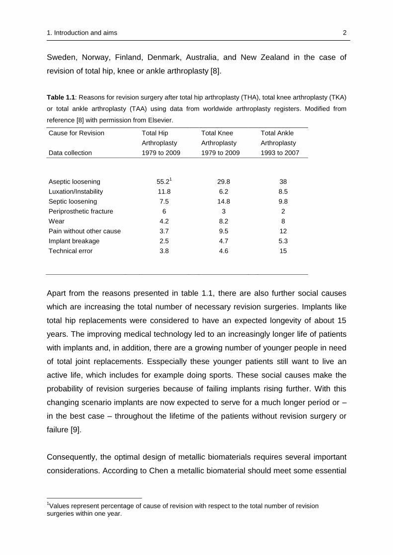
patients and most frequently the need for revision [7]. Among the list of different
indications for revision surgery, one particular is aseptic loosening (see table 1.1).
Aseptic loosening can often be related to insufficient properties of the implanted
materials, which will be explained in the section below. Reasons for the necessity of
revision surgeries are exemplarily shown in table 1.1, using register data from
1. Introduction and aims 2
Sweden, Norway, Finland, Denmark, Australia, and New Zealand in the case of
revision of total hip, knee or ankle arthroplasty [8].
Table 1.1: Reasons for revision surgery after total hip arthroplasty (THA), total knee arthroplasty (TKA)
or total ankle arthroplasty (TAA) using data from worldwide arthroplasty registers. Modified from
reference [8] with permission from Elsevier.
Cause for Revision
Total Hip
Total Knee
Total Ankle
Arthroplasty
Arthroplasty
Arthroplasty
Data collection
1979 to 2009
1979 to 2009
1993 to 2007
Aseptic loosening
55.21
29.8
38
Luxation/Instability
11.8
6.2
8.5
Septic loosening
7.5
14.8
9.8
Periprosthetic fracture
6
3
2
Wear
4.2
8.2
8
Pain without other cause
3.7
9.5
12
Implant breakage
2.5
4.7
5.3
Technical error 3.8 4.6 15
Apart from the reasons presented in table 1.1, there are also further social causes
which are increasing the total number of necessary revision surgeries. Implants like
total hip replacements were considered to have an expected longevity of about 15
years. The improving medical technology led to an increasingly longer life of patients
with implants and, in addition, there are a growing number of younger people in need
of total joint replacements. Esspecially these younger patients still want to live an
active life, which includes for example doing sports. These social causes make the
probability of revision surgeries because of failing implants rising further. With this
changing scenario implants are now expected to serve for a much longer period or –
in the best case – throughout the lifetime of the patients without revision surgery or
failure [9].
Consequently, the optimal design of metallic biomaterials requires several important
considerations. According to Chen a metallic biomaterial should meet some essential
1Values represent percentage of cause of revision with respect to the total number of revision
surgeries within one year.
1. Introduction and aims 2
requirements to fulfill its use as a safe medical application even in long-term
applications [6]:
(1) Suitable mechanical properties
(2) Excellent biocompatibility (non-toxic)
(3) High corrosion resistance
(4) High wear resistance
(5) Osseointegration (in the case of bone prosthetics)
There are several important properties that are necessary for a metallic implant to
perform well in long-term usage. The mechanical properties are the first requirement
to be mentioned because they decide which type of material has to be used for a
demanded application [9]. In case of reconstructive surgery like orthopedics the
superior mechanical properties of metals are the main reason for their predominant
role and - together with their good fabrication properties - why they form a major
portion of the available biomaterials [6], [10]. Young’s modulus, ultimate tensile
strength (UTS), and toughness are mechanical properties that are of general
importance for the development of biomaterials [6]. The long-term success of an
implant being used under cyclic loading is determined by its fatigue strength. This
property gives the response to repeated cyclic loads or strains and failing leads to so-
called fatigue fracture and is often associated with aseptic loosening [9], [11]. In
applications where metallic biomaterials have to replace bone, they have to fulfill a
variety of different requirements. They have to be stiff enough to resist deformation
and sustain loads under pressure. In addition, they have to be flexible to absorb
energy from deformation while becoming wider and shorter when compressed, or
respond to tension by lengthening and narrowing without cracking [12]. According to
Mantripragada the materials chosen for these applications should meet these
contradictory requirements of stiffness vs. flexibility and lightness vs. strength [12].
Failing of an implant because of a given mismatch of mechanical properties or
insufficient strength is referred to as biomechanical incompatibility [9]. An example for
an issue due to biomechanical mismatching that is very common for currently used
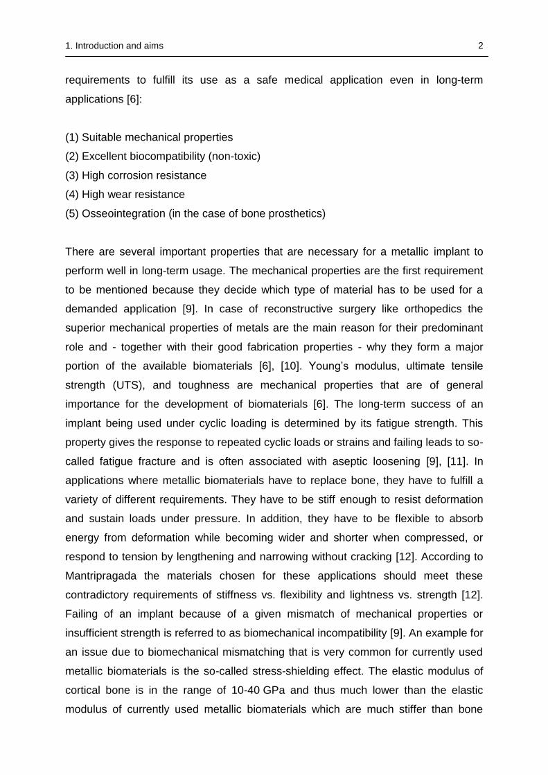
metallic biomaterials is the so-called stress-shielding effect. The elastic modulus of
cortical bone is in the range of 10-40 GPa and thus much lower than the elastic
modulus of currently used metallic biomaterials which are much stiffer than bone
1. Introduction and aims 3
(table 1.2) [13]. Bone that is subjected to loading or stress regenerates, whereas the
absence of loading results in atrophy. A much stiffer implant reduces the loading on
the bone; stress transfer to adjacent bone is insufficient, which results in the effect
called stress shielding [14]. It could also be shown that the degree of stress shielding
is directly depending on the difference between the stiffness of bone and the
implanted material [15]. The weakening of the stress-shielded bone leads to a
deteriorating interface to the implant, which can result in loosening of the implant but
also fracture of the bone, the interface, or even the implant itself [16]. In order to
prevent loosening of an implant and avoid revision surgery, a biomaterial that is
designed for these applications should have an excellent combination of low modulus
and high strength [9].
Table 1.2: Mechanical properties of metallic biomaterials and bone (modified from reference [13] with
permission from Elsevier).
Materials Young’s modulus
Yield strength Ultimate tensile strength
E (GPa) YS (MPa) UTS (MPa)
cp-Ti
105 692 785
Ti-6Al-4V
110 850-900 960-970
Ti-6Al-7Nb
105 921 1024
Ti-35Nb-5Ta-7Zr 55 530 590
CoCrMo
200-230 275-1585 600-1795
Stainless Steel 316 L 200 170-750 465-950
Bone 10-40 / 90-140
One of the most crucial requirements for a biomaterial is its biocompatibility. The
biocompatibility of a material indicates its ability to perform in conjunction with a living
system [17]. This means that the materials used for implants should not only be non-
toxic, but should also not induce any inflammatory or allergic reactions in the human
body [9]. An ultimate failure in metallic implants may be due to the release of toxic
ions or toxic amounts of ions and thus result in the rejection of an orthopedic implant.
To prevent measurable inflammation or allergic reactions a metallic biomaterial
should be made of non-toxic elements. A material introduced in the human body
could cause harm in different ways such as cytotoxicity (cell death), carcinogenicity
(cancer formation), mutagenicity (genetic damage), pyrogenicity (immune responses)
1. Introduction and aims 4
or thrombogenicity (blood clotting) [6]. The concept of biocompatibility was introduced
in order to assess the biological behavior of synthetic materials, which is depending
on two main factors, namely the host response induced by the implanted material
and its degradation in physiological environment [18], [19]. According to Hench and
Polak one can further distinguish between three generations of biomaterials [20]. The
first generation, in which most of the metallic biomaterials can be placed, can be
described as bioinert materials. Their only requirement is to achieve physical
properties to match those of the replaced tissue with reducing the reaction of the host
to a minimum. The bioactive materials of the second generation should be able to
interact with their physiological environment to induce a controlled reaction and
enhance tissue bonding. The stimulation of specific cellular responses on a molecular
level is the key feature of the third generation biomaterials.
Corrosion resistance is another important non-mechanical requirement for metallic
implants designed for long-term service in the body. A metal that is inert or passive in
air may suffer severe corrosion in physiological environment, which is physically and
chemically extremely different from ambient air and hence presents a highly corrosive
milieu for metallic implant materials [21]. Corrosion is accelerated by different factors
and many of them can be found inside the human body, e.g. aqueous ions like Na+
and Cl- from saline-containing body fluids, debris and cellular material that can
adhere to the implant as well as decreasing pH values due to inflammation or after
surgery [6], [22]. In addition, the lower oxygen content in the human body accelerates
the corrosion of the metallic implants, because it slows down the repassivation of the
oxide layer protecting the metals in case they are damaged [23]. The extensive
release of metal ions from a metallic implant surface can adversely affect the
mechanical integrity of the implant as well as induce adverse biological reactions of
the host, which can ultimately lead to failure of the device or even worse in the case
of undesirable toxic ions or corrosion products shorten the life of humans [24], [10].
Under optimal circumstances the release of metal ions should be reduced to a
minimum even at most aggressive conditions and remain low in normal physiological
environment to ensure a longevity of the metallic implant [6].
Another required property of metallic biomaterials which is closely connected to
corrosion resistance particularly in load-bearing applications is the resistance against
1. Introduction and aims 5
wear. This property is especially demanded in applications where lots of movement
or cyclic loading is expected, as for example for the different components of artificial
joints. Low wear resistance of materials results in aseptic implant loosening and in
the generation of wear debris, which may provoke adverse reactions in the
surrounding tissue. An increased amount of particles generated by wear in long-term
applications attracts cells of the immune system, especially macrophages which
phagocytize the particles and possibly die [25]. The death of the macrophages is
accompanied by a release of enzymes and metabolites, which results in acidification
of the surrounding environment. The combination of released ions and debris from
the implant surface as well as released enzymes and the acidified environment leads
to the further erosion of the implant and the surrounding bone and is one possible
reason for aseptic loosening of the implant [6]. Apart from the problems the
generated wear particles are causing at the implant site they can also become an
issue in other locations since they are typically distributed throughout the body and
may even cause systemic inflammation [26].
For biomaterials that are frequently used in applications where they are in direct
contact to bone, osseointegration, which describes the formation of new bone and
bone healing, is a fundamental requirement, especially when these implants are
intended to stay there for a long period of time [7]. This is not the case for temporary
devices such as bone screws and plates, which are removed before bone bonding
occurs, in order to avoid bone re-fracture during the removal operation [27]. An
implant which is insufficiently bonded to adjacent bone because of micromotions of
the device gets encapsulated by fibrous tissue that forms between the bone and the
biomaterial surface. Poor integration into bone and the subsequent formation of
fibrous tissue promotes further loosening of the implant [7].
The surface of the prosthesis plays an important role in its integration into the
surrounding bone. Key characteristics that have to be considered for the essential
bone bonding ability of a biomaterial are surface chemistry, roughness, porosity and
topography [28]. Within a period of micro- to milliseconds after the implant has been
inserted into the body its surface is being covered and preconditioned by a mixture of
ECM proteins, such as albumin, fibronectin and vitronectin, which mask the surface
of the implant [29]. After this preconditioning with proteins the cells responsible for
1. Introduction and aims 6
osseointegration - mesenchymal stem cells, osteoblasts and osteoclasts - can
adhere to the surface [30]. However, cells are not the only biological species that is
able to adhere to these proteins. Bacteria like Staphylococcus aureus (SA) or
Staphylococcus epidermidis (SE) can also adhere to the protein-covered surface
[31]. The adherence of bacteria to the biomaterial surface, covered or uncovered by a
protein layer, leads to so-called implant-associated infections, which represent a
serious complication for the patient and result in long-term treatment with
unpredictable success that often ends with the removal of the primary implant [32].
The reasons for the occurrence of post-operative infections are mainly the
contamination of the implant surfaces by bacteria during the implantation, but they
can also be caused by a hematogeneous bacterial spreading after e.g. the extraction
of a tooth [33]. After the explantation of infected implants the common treatment
includes the removal of the surrounding infected tissue as well as the implantation of
a polymethyl methacrylate (PMMA) spacer or according cements which are loaded
with antibiotics [34], [35], [36]. As presented in table 1.1, the implant-associated
infections are a major reason for necessary revision surgeries. The treatment of
infections is thereby aggravated by the ability of the adhering bacteria to form
biofilms. Protected in this self-produced amorphous matrix of exopolysaccharides,
DNA and proteins, the growing bacteria colonies are very hard to kill with antibiotics
[37]. The situation will become even more complicated since the liberal use of
antibiotics during the last decades led to an increase in antibiotic-resistant organisms,
especially methicillin-resitant staphylococcus aureus (MRSA), which results in an
additional major therapeutic challenge [38]. A promising strategy to prevent the
adherence of bacteria to the biomaterial in the first place could be an antimicrobial
modification of the implant surface [37].
Regarding all issues that were mentioned in the section above, only the mechanical
properties like elastic modulus or ultimate tensile and fatigue strength are directly
related to the bulk material of the implant. Other properties that are also of crucial
importance for the success of a metallic biomaterial for example corrosion and wear
resistance, biocompatibility or depending on the application, properties like
osseointegration, are mediated by the surface of these materials. This explains the
huge interest and efforts that are conducted to use modification methods to improve
particularly the surface of metallic implants.
1. Introduction and aims 7
There is a permanently increasing number of different surface modification methods
to adjust these properties, such as anodization, electrodeposition, chemical vapor
deposition, plasma spraying, sol-gel methods, which address various problems of the
bulk materials [10], [39], [40]. Metals are mostly used in substitution for hard tissue,
but the serious problems with metallic ion release and wear debris in joint
replacement surgery have to be overcome to guarantee safe application. A specific
disadvantage of typically artificial metallic biomaterials is their lack of biofunctionality
as metallic surfaces usually form a clear interface against living tissue, which acts as
a barrier to conduct biofunctions [40].
The fabrication process of metals and their alloys usually involves the application of
very high temperatures during melting, casting, forging, and subsequent heat
treatments; hence surface modifications cannot be added during the manufacturing
process. There are many different approaches to improve the metallic surfaces to
enhance their corrosion and wear resistance as well as their bone conductivity, while
leaving the mechanical properties of the bulk material untouched [41]. In this work,
three different surface modification techniques were used, namely physical vapour
deposition (PVD), oxygen diffusion hardening (ODH) and electrochemical
anodization, whereby the basic step in all applied modifications was always the
coating via PVD.
The aim of this thesis was the development of functional PVD coatings which are
suitable for further treatment with other surface modification techniques, thus
combining the advantages of functional coatings with the improved material
properties induced by a subsequential modification, namely oxygen diffusion
hardening (ODH) and nanostructuring by electrochemical anodization.
The term physical vapour deposition (PVD) describes a number of different coating
techniques which have in common that the vaporization of materials takes place by
physical means with the subsequent deposition of these vaporized materials on a
substrate [42]. This versatile surface modification method has proven its usefulness
for biomaterials in many different studies, including the deposition of pure materials
such as tantalum (Ta), which is due to its biocompatibility a biomedically highly
interesting metal, as well as enhanced osseointegration capability and corrosion
1. Introduction and aims 8
resistance compared to titanium, which also shows a self-healing effect due to the
fast repassivation of the surface [43], [44]. Since the material price of Ta is
approximately ten-fold the price of titanium and due to its very high density of
16.626 g/cm3 a Ta bulk metal implant for the use in e.g. orthopedics would be too
expensive and too heavy; however, its favorable properties makes it an extremely
attractive material for the application as thin film [45], [46].
Apart from coatings consisting of only one single material, it is also possible to
generate coatings consisting of more material components. One strategy to create
biofunctionality in titanium PVD coatings is the generation of Ti layers doped with
biologically active metals like silver (Ag) or copper (Cu). This can be achieved by
simultaneous deposition of the two materials, which is usually performed by using
two sputtering sources or an alloy target. In this way biocompatible and antimicrobial
coatings such as silver doped titanium (Ti(Ag)) may be fabricated [47].
Oxygen diffusion hardening (ODH) is a surface modification method that can improve
the tribological properties of metals by dissolving atomic oxygen in the metallic crystal
lattice with a decreasing concentration of oxygen from surface to bulk of the treated
material, resulting in a gradient-like transition zone between the high hardness of the
surface and the softer bulk material [48]. The risk of delamination, which is a common
issue for abrasion resistant PVD coatings due to the abrupt transition between the
brittle-hard properties of the coatings and the ductile properties of the substrate,
could be reduced due to the gradient-like hardness profile created by the smooth
transition zone of dissolved oxygen.
Electrochemical anodization is a relatively simple and inexpensive method to create
nanostructures on refractory metals such as titanium, tantalum and niobium as well
as on their alloys [49], [50], [51], [52]. The application of appropriate process
parameters for anodization induces a self-ordering effect, which results in the
formation of controllable nanotubular structures by a simultaneous oxidation and
dissolution of the metals in the fluoride-containing electrolytes [53]. These nanotube
surfaces are biocompatible, and their beneficial osseointegrative potential, which is
significantly depending on the tunable nanotube diameters, could already be
demonstrated in in vitro and in vivo experiments [54], [55]. The strong
osseointegrative potential of nanotubular coatings could also avoid micromotions
between implant and bone and hence, reduce the danger of wear-induced implant
failure.
1. Introduction and aims 9
The combinations of these surface treatments could couple the advantages of a
highly attractive but comparably expensive and “soft” material like tantalum with the
enhanced wear resistance of ODH or the antimicrobial potential of functional coatings
like silver doped titanium (Ti(Ag)) with the improved osseointegration properties of a
nanotubular structured TiO2 surface. These subsequent modifications of PVD
coatings provide the opportunity to use these coupled processes on a variety of
different substrate materials, thereby further widening the application field of these
modified and functionalized surfaces. The specific aims that need to be achieved for
this study are:
1) Creation of a biocompatible and abrasion resistant coating on titanium by
improving the wear resistance of tantalum PVD layers by subsequent oxygen
diffusion hardening
2) Development of a versatile method to produce functional coatings of doped
titanium using only one deposition source without the need of expensive and
inflexible alloy targets
3) Nanostructuring of pure or doped Ti-PVD coatings on different substrates by
electrochemical anodization in fluoride-containing electrolytes and optimization of
coating and anodization process parameters
2. State of the art 10
2 STATE OF THE ART
2.1 Metals as Biomaterials
Metals as biomaterials have many different application sites ranging from craniofacial
and maxillofacial applications to applications in non-osseous tissues like stents set in
blood vessels or cases and electrodes for pace makers [6]. Despite the fact that
metals have been substituted by polymers and ceramics in many applications due to
their often excellent biocompatibility and biofunction, metals make up over 70 % of
implant devices in the medical field (including dentistry). This share is even exceeded
by a 95 % share of implant devices in orthopedics and according to Hanawa this
share will be maintained because of their superior mechanical properties [40]. This
major application where metals play an absolutely predominant role include load-
bearing implants, such as hip and knee prostheses and fracture fixation wires, pins,
screws, and plates. The implantation site is an important aspect that should be
considered for the success of an implanted metallic biomaterial. A metallic
biomaterial that could not be used for orthopedic applications because of insufficient
mechanical properties, could still be used for cardiovascular applications, provided it
does not induce negative effects such as for example blood clotting [6]. Thus the
success of different metallic materials is not only depending on the knowledge about
their physical and chemical properties; knowledge about the interaction between the
metallic biomaterials with the host tissue of the human body is another crucial aspect
[56]. Metallic biomaterials are rarely used in their pure form. Alloys often show
superior material properties like corrosion and wear resistance. Still there are only
few metals and alloys which meet the required challenging combination of suitable
mechanical properties, biocompatibility, and corrosion and wear resistance as well as
reasonable costs with varying degrees of success. Three material groups that will be
further described in the following section have been dominating the field of
biomedical metals for the last decades: Stainless steel, cobalt-chromium-
molybdenum alloy (CoCrMo alloys), titanium and titanium alloys [56].
2.1.1 Stainless steel
Implants made from stainless steel have excellent fabrication properties, high
strength, suitable biocompatibility and are predominantly applied as temporary low
2. State of the art 11
cost materials for osteosynthesis devices like in fracture plates, screws and hip nails
but they are also used in the case of total hip replacements as permanent implants
[57], [58], [59]. Stainless steels are iron (Fe) based alloys that contain next to varying
amounts of nickel (Ni) a high percentage of chromium in the range of 10-30 wt% [60].
Stainless steels can be either grouped according to their chemical composition
(chromium or chromium-nickel) or alternatively according to their microstructure
(martensitic, austenitic, ferritic or duplex) [61]. Martensitic steels are being used in the
medical field for the fabrication of surgical instruments because of their high hardness
but only austenitic stainless steels are used for implants. Implant grade austenitic
stainless steel such as 316L have a typical alloying composition such as 17-19 wt%
Cr, 13-15 wt% Ni, and 2.25-3.00 wt% of Mo [60]. The high percentage of chromium
leads to a chromium-rich oxide film on the surface which is corrosion resistant, about
2 nm in thickness, strongly adhesive and has self healing abilities in the presence of
oxygen [62], [18]. The addition of nickel leads to the stabilization of the austenitic
phase and improves not only the corrosion resistance but also many mechanical
properties of the material [60]. Molybdenum is added for further protection against
pitting corrosion by trapping carbon. This prevents the formation of chromium
carbides which would result in the formation of chromium depleted regions and
weakening of the passive layer [63]. Despite of this protective oxide layer implanted
stainless steel devices often show signs of degradation from pitting, crevice
corrosion, corrosion fatigue, stress corrosion cracking and galvanic corrosion [10].
The damaging of the material by various forms of corrosion is accompanied by the
release of potentially toxic ions, especially nickel, which is another issue with
stainless steels [64], [65].
Stainless steel implants of the 316L type also have a comparably low resistance
against wear and loosening of an implant can be caused by a large amount of wear
debris [7]. The 316L stainless steel alloys are widely accepted but regarding their
long-term performance as implanted material they often fail due to corrosion, wear or
a combination of both in the highly corrosive environment of the human body. As
mentioned in the beginning, this means that their use is now more or less restricted
to temporary applications for internal fixation which are removed after the healing
process is completed [6]. The problems caused by nickel ion release led to the
development of nickel-free austenitic steels with a high nitrogen content, which
improves the austenitic structure stability and hence the resistance against corrosion
2. State of the art 12
and wear [66]. The development of these nickel-free stainless steels (Orthinox) has
maintained the leading role of stainless steels as material for stems in total hip
replacements which occupy almost 70 % of the market in the United Kingdom [6].
2.1.2 Cobalt based alloys
The first use of cobalt based alloys as an implant material was in the 1930s. Before
usage as a material for orthopedic applications in the 1940s CoCrMo alloy was used
as a cast dental alloy [60]. Basically two types of cobalt based alloys can be
distinguished: CoCrMo alloys and CoNiCrMo alloys. Castable CoCrMo (e.g. ASTM F-
75: Co28Cr6Mo) alloys have been in use in dentistry and in producing artificial joints
for a long time. The wrought CoNiCrMo alloy (e.g. F562: Co35Ni20Cr10Mo) is a
relatively new material which is used for heavily loaded applications, e.g. the stems of
total hip or knee prostheses [67]. The mechanical properties of cobalt-based alloys
are superior to that of stainless steels and especially in chloride environments they
posess a much higher corrosion resistance [18]. In physiological environment a
passive oxide layer forms spontaneously on the surface due to the high chromium
content. The other alloying elements such as Mo and Ni are also strengthening the
corrosion resistance in the same way as described in stainless steels [60].
The mechanical properties of a typical CoCrMo alloy are listed in table 1.2. These
alloys have a high elastic modulus of 220-230 GPa which is quite similar to that of
stainless steel of about 200 GPa, but much higher than that of cortical bone which is
in the range of 10-40 GPa; hence stress-shielding accompanied by atrophy and
aseptic loosening remains a general issue [26]. Compared to stainless steels cobalt
based alloys are in general superior when it comes to resistance against corrosion,
fatigue and wear. Their properties make them a good choice for a wide range of
medical applications from all metallic components of joint replacements to fracture
fixation devices [6]. According to Chen, the prostheses for knee and ankle
replacements consist almost exclusively of CoCrMo alloys with a lining made of ultra-
high-molecular-weight polyethylene (UHMWPE). In the case of total hip
replacements, around 20 % have stems and/or the hard-on-hard bearing system
made out of wrought CoCrMo alloys [6].
2. State of the art 13
There are several issues that have to be mentioned regarding these alloys. Failure of
these materials can occur due to fretting and corrosion fatigue, aseptic loosening due
to the formation of wear debris as well as stress shielding effects [6]. Another issue is
the biological toxicity of Co, Cr, and Ni ion or particle release [68]. The percentage of
the medical market is also limited because of the high cost of these alloys which
differs a lot depending on the production method and the resulting properties
(casting: lower price - forging: maximum strength) [60]. The expensiveness of these
alloys compared to stainless steel is also a reason why their usage is limited in more
temporary applications like fracture –fixation systems.
2.1.3 Titanium and Ti alloys
The initial commercial development of titanium began in the 1940s, and it was
evaluated as a material for surgical implants soon afterwards when the excellent
tissue compatibility was shown by early animal experiments [69], [70], [71]. The
medical applications, where Ti and its alloys have been successfully used, include
dental implants, bone fixation devices like nails, plates and screws, joint replacement
components such as finger, shoulder, knee and hip, pacemaker cases, artificial heart
valves, and surgical instruments [56].
In comparison to iron and cobalt as the main components of stainless steels or
cobalt-chrome alloys, respectively – titanium has a much lower density, only about
60 % of that of iron and 50 % of the density of cobalt. The decrease in density and
therefore weight of an implant becomes especially important to older people or frailly
build individuals such as children, since the lighter implants considerably improve the
recipient’s comfort. [72]. Compared to stainless steels and cobalt-chrome alloys,
titanium and its alloys exhibit a superior specific strength, i.e. the ratio between
strength and density. They have also shown to be better in terms of biocompatibility
and corrosion resistance; this is associated with the adhesive stable layer of titanium
dioxide (TiO2) that is formed on the surface and in case of damage can be rebuilt in
physiological fluids [9]. One of the biggest advantages of titanium and its alloys is the
lower elastic modulus of 110 GPa which is only approximately 50 % of the elastic
modulus of stainless steels and CoCrMo alloys (see table 1.2). The elastic modulus
which is much closer to that of bone reduces the problems related to stress shielding
2. State of the art 14
in total hip replacements, where a prostheses with a lower elastic modulus, i.e. an
implant that is more flexible, exhibits better distribution of stress to the surrounding
bone tissue and thus reduces the risk of loosening and failure [69], [73]. Another
most advantageous property of titanium and its alloys is their capacity to become
tightly integrated into bone, which has been intensively studied since the 1970s [74].
In contrast to CoCrMo alloys and stainless steel, Ti implants are not permanently
surrounded by a thin fibrous capsule, but show direct contact to bone [75]. This ability
considerably improves the long-term performance of these implants and reduces the
risk of implant failure and loosening [76].
Unalloyed commercially pure titanium (cp Ti) is divided into four different grades
depending on the amount of impurities, primarily of oxygen and iron. The commonly
used forms of titanium are grade 4 (ASTM grade 4, highest oxygen and iron content
of up to 0.50 and 0.40 wt%, respectively) and titanium alloyed with aluminum (Al) and
vanadium (V) Ti-6Al-4V because of their excellent mechanical and chemical
properties, with Ti-6Al-4V gradually replacing the unalloyed titanium due to its higher
mechanical strength [12], [77]. Based on their microstructure, which is depending on
their chemical composition, alloying elements, and processing, there are four
different types of titanium alloys: alloys (hexagonal close packed (hcp) crystal
structure, e.g. cp Ti), near- alloys (only small addition of stabilizers), alloys
(e.g. Ti-6Al-4V), and alloys (body centered cubic (bcc) crystal structure) [78].
Compared to alloys, phase alloys are more suitable for load-bearing
applications. They show a lower elastic modulus and satisfy most of the requirements
for an orthopedic implant application [79]. Due to their lower strength the usage of
and near- alloys has been limited in the field of medical implants, but they are
preferred for non-load-bearing, corrosion resistant applications, e.g. pace-maker
cases, dental implants, as well as maxillofacial and craniofacial implants [6].
To overcome the mechanical restrictions of cp Ti it was substituted by titanium alloys
such as Ti-6Al-4V, which in relation to cp Ti shows typically twice the values for yield
and ultimate strength [18]. The alloying elements aluminum and vanadium which are
responsible for the favorable mechanical properties of this alloy, raised some
concern, as the gradual release of Al and Va ions from the alloy’s surface has shown
to be associated with local adverse tissue reactions, immunological responses and
2. State of the art 15
long-term health problems, such as Alzheimer’s disease and neuropathy [80], [77],
[81], [82], [69]. The potential toxicity of vanadium and the concerns about issues with
aluminum led to a search for different alloying materials which resulted first in the
introduction of Va-free alloys like Ti-6AI-7Nb in the 1980s which have the same
structure as Ti-6Al-4V with equivalent good mechanical properties and a
corrosion resistance equal to cp titanium and Ti-6Al-4V [69], [83]. The type alloys
often described as second generation of titanium biomaterials which are free of
aluminum and vanadium were developed in the 1990s [6]. Another reason for the
design of the new alloy was a lower elastic modulus in order to further reduce the
problems related to stress shielding [69]. In comparison to Ti-6Al-4V alloy the new
type alloys exhibit an enhanced biocompatibility because of their alloying elements
niobium, tantalum, zirconium (Zr) and molybdenum [84]. Together with their
enhanced biocompatibility these alloys show a superior corrosion resistance and a
lower elastic modulus with values down to 35 GPa for the quaternary alloy Ti-29Nb-
13Ta-4.6Zr (TNZT alloys), - which is quite similar to that of human cortical bone [81],
[85]. But in order to lower the high cost of these implants, which is considered the
main reason behind the ease of commercialization, there are already suggestions
and studies to replace the rare, expensive and high melting point metals like Ta, Nb,
Zr and Mo [86]. Especially the high cost of the raw materials for the alloys, which
contain a considerable amount of Ta, Nb, and Zr, and the difficulties in fabrication
due to the high melting point of these components led to the proposed replacement
with cheaper elements, such as iron, chromium, manganese (Mn), tin (Sn) and
aluminum [87]. In addition to the expensiveness of these alloys, a major drawback of
type alloys is their lower fatigue strength and ultimate tensile strength compared to
alloys [6]. Another drawback especially of the softer alloys but also of cp Ti and
the other titanium based alloys is their poor resistance to wear [6], [88]. The poor
tribological behavior of titanium and its alloys compared to stainless steels and Co-Cr
based alloys restrains its use as implant material in some cases as it suffers from
severe wear when rubbed between itself or between other metals [7]. The decline for
usage in applications for load-bearing surfaces was due to many cases of aseptic
loosening linked with the creation of metallic particulate debris [89], [90]. Tissue
blackening and metallosis occurred as a consequence of debris formation in load
bearing applications because of the formation of a poorly adhering surface oxide
2. State of the art 16
layer which periodically detached from the surface [39]. Due to their tribological
properties the use of titanium and its alloys as implant materials is limited to
applications where the resistance to wear is not of vital importance. Thus, for
example, the femoral stem of an hip implant is often made of a titanium alloy but it’s
not recommended for use as a femoral head [79].
Regarding the field of metallic biomaterial development, a lot of research is going on
to overcome issues with the currently used metals and alloys. As shown in the
section above, the currently used implant materials have some disadvantages but
especially in the field of orthopedic implants their superior mechanical properties
make them the first choice for these applications [12]. Developments to improve the
performance of metallic implanted materials such as minimizing the effects caused by
toxic ions by replacing nickel in nickel-free stainless steels or using alloys with lower
elastic modulus like the new titanium based alloys may only solve some of the
issues. According to Chen, the perfect metallic biomaterial should have the strength
of cobalt-chrome alloys, the elastic modulus, corrosion resistance, and
biocompatibility of titanium, while being as cheap as stainless steel [6].
2.2 Principles of physical vapor deposition
One can distinguish between four different physical vapour deposition (PVD)
processes: sputter deposition, arc vapour deposition, vacuum evaporation and ion
plating. In physical vapour deposition processes atoms or molecules from a solid or
liquid- target material get vaporized by means of heating (e.g. evaporation) or
sputtering by ions [91], [92], [93]. The vaporized material is transported to the
substrate in vacuum or a low pressure atmosphere and condenses on the substrate.
A wide range of different materials can be deposited by PVD processes such as
metals, semiconductors, and ceramics [94], [95], [96], [97]. Also coatings consisting
of alloys and compounds can be created using PVD processes [98], [99]. Titanium
nitride (TiN) or titanium dioxide (TiO2) as examples for compound materials are
usually deposited by reactive sputtering. In this case a reactive gas species like
nitrogen or oxygen is added to the process gas [100], [101]. The deposited films have
a thickness range from a few nanometers to several micrometers and can consist of
2. State of the art 17
single or multilayer coatings, even with composition gradients [102], [103], [104],
[105]. There are many applications and substrates differing in size and geometry
from watches to complete solar panels in which PVD processes are used to create
protective, decorative or functional coatings [106], [107], [108]. The only PVD-
method that was used in this thesis is sputtering; hence the other PVD- processes
mentioned in this introduction will not be explained in further detail.
2.2.1 Sputter deposition
Sputter deposition is a non-thermal vaporization process where physical sputtering is
used to vaporize particles from a surface and subsequentially get deposited on a
substrate [42]. During sputter deposition processes a target that consists of the
desired coating material is bombarded by energetic gaseous ions which are created
in a low-pressure plasma. The impulse of these ions is transferred to the target atoms
which as a result are physically ejected from the surface of the target. These
vaporized particles are transported to the substrate and condensate on the surface,
where finally the growing of the film occurs. On the way from the vaporization source
to the substrate the sputtered atoms can collide with gas atoms. Due to these
collisions the sputtered atoms lose energy. In order to reduce the number of
collisions and thus create a long mean free path these sputtering processes are
performed in a low-pressure atmosphere, typically below 1*10-2 mbar [109].
Experimental setup for RF – and RF- magnetron sputtering
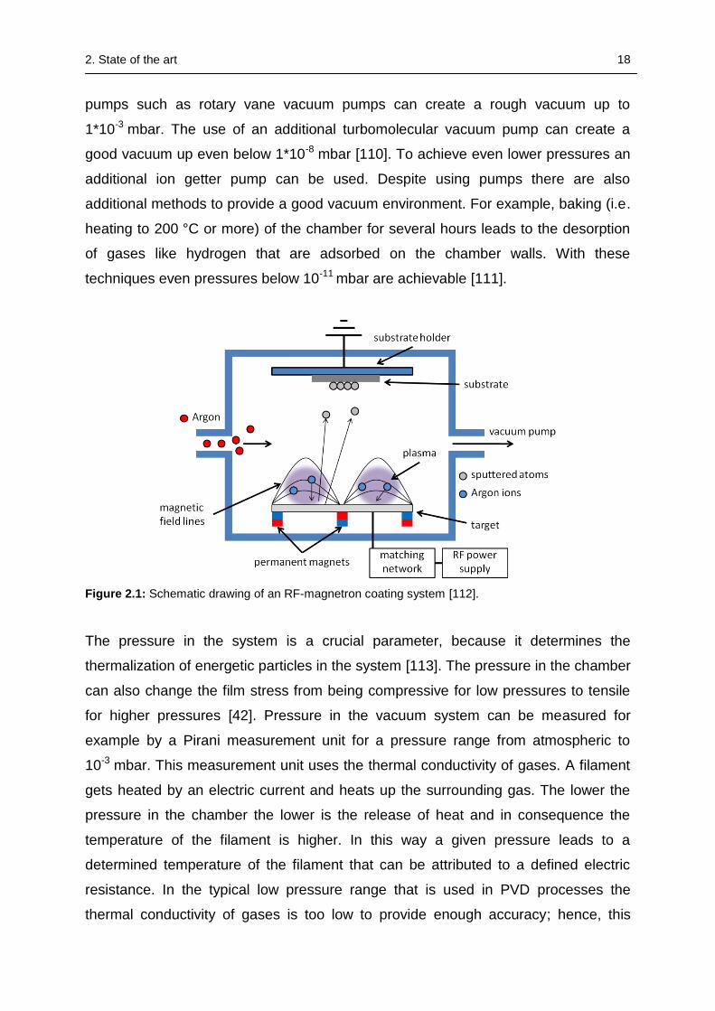
A scheme of an RF-magnetron deposition chamber is shown in figure 2.1. Basic
components of such a deposition chamber are a vacuum pumping system, inlets for
inducing the process gas and additional reactive species, the target consisting of the
material that should be sputtered, an RF-network that is attached to the target, and a
usually grounded substrate holder.
The first step of a deposition process is the evacuation of the chamber down to a
pressure of typically lower than 10-6 mbar which is considered as a “good” vacuum
[42]. Fine vacuum environment is important for the control of the amount of gaseous
and vapour contamination in the process. Additionally, as described above, a lower
pressure extends the mean free path of the sputtered atoms [42]. To achieve such
low pressures a combination of different vacuum pumps is needed. Mechanical
2. State of the art 18
pumps such as rotary vane vacuum pumps can create a rough vacuum up to
1*10-3 mbar. The use of an additional turbomolecular vacuum pump can create a
good vacuum up even below 1*10-8 mbar [110]. To achieve even lower pressures an
additional ion getter pump can be used. Despite using pumps there are also
additional methods to provide a good vacuum environment. For example, baking (i.e.
heating to 200 °C or more) of the chamber for several hours leads to the desorption
of gases like hydrogen that are adsorbed on the chamber walls. With these
techniques even pressures below 10-11 mbar are achievable [111].
Figure 2.1: Schematic drawing of an RF-magnetron coating system [112].
The pressure in the system is a crucial parameter, because it determines the
thermalization of energetic particles in the system [113]. The pressure in the chamber
can also change the film stress from being compressive for low pressures to tensile
for higher pressures [42]. Pressure in the vacuum system can be measured for
example by a Pirani measurement unit for a pressure range from atmospheric to
10-3 mbar. This measurement unit uses the thermal conductivity of gases. A filament
gets heated by an electric current and heats up the surrounding gas. The lower the
pressure in the chamber the lower is the release of heat and in consequence the
temperature of the filament is higher. In this way a given pressure leads to a
determined temperature of the filament that can be attributed to a defined electric
resistance. In the typical low pressure range that is used in PVD processes the
thermal conductivity of gases is too low to provide enough accuracy; hence, this
2. State of the art 19
measurement unit is being used for pressure control in the pre-evacuation [109]. To
determine lower pressure values, a Pirani measurement unit can be combined with a
Penning measurement system. These so called cold cathode measurement units use
high voltage and a strong magnetic field to create a constant gas discharge and
measure the ion current of this discharge. The analysed ion current is depending on
the pressure of the system and can thus be used to determine the pressure.
After evacuating the chamber to achieve a good vacuum environment the process
gas is induced into the chamber. An AC voltage with a frequency of 13.56 MHz is
applied to the target, which leads to the ionization of the process gas and thus the
ignition of the plasma [114]. The target is coupled to the plasma via a capacitor that
prevents the drainage of charge carriers [115]. The electrons in the plasma have a
higher mobility compared to the gas ions in the plasma. Therefore, during the positive
half-wave of the alternating voltage more electrons reach the target than positively
charged gas ions during the negative half-wave of the cycle: A negative voltage is
built up between the cathode and the plasma because the cathode is isolated by the
capacitor [116]. This so-called bias voltage reaches a constant value when the ion
and electron current reach an equilibrium over time, and thus leads to the
bombardment of the target by positively charged ions that are extracted from the gas
[117]. Because of the lower mobility of the ions compared to the electrons positively
charged gas ions are hitting the target approximately for the whole period of the
alternating voltage [114]. To prevent so-called resputtering from atoms of the growing
film on the substrate the whole potential drop has to drop before the target. This is
accomplished by an adjustment network consisting of two capacitors which in this
way reduces the amount of resputtering effects to negligible amount [116]. During the
positive half-wave of the cycle, electrons are hitting the target and in this way prevent
any charge buildup [42]. To sustain permanent plasma the ions hitting the target must
generate a sufficient number of secondary electrons, which in return ionize atoms in
the plasma, to compensate the ion loss due to sputtering of the target.
To complete the experimental setup of the PVD system there must be a cooling
system for the target. The bombardment of the target by ions from the plasma leads
to an energy transfer from the ions to the atoms of the target which in return get
ejected or sputtered. The most fraction of energy transferred to the target atoms is
2. State of the art 20
transformed to heat; therefore the target must be cooled to prevent damaging of the
target and the associated equipment. Cooling of the target in addition prevents heat
radiation, and therefore allows the substrate holder to be mounted relatively close to
the target. Thus providing shorter distances to cross for the sputtered atoms,
resulting in higher energies of those atoms when they reach the substrate [113].
In RF-magnetron sputtering additional permanent magnets are installed behind the
target. In this way, the path of electrons in the vicinity of the target surface is
extended and the degree of ionization of the plasma is enhanced; a process that will
be further explained in detail.
Electrons are released from the target surface by the bombardment of the positively
charged gas ions and are subsequently accelerated away from the target by the
electric field during the negative half-wave of the cycle [42]. The electrons leaving the
target are now additionally under the influence of the magnetic field created by the
permanent magnets behind the target. An electron trap is now formed by the
magnetic field lines together with the target surface. The Lorentz force confines the
drift currents of the electrons to a closed-looped path on the surface of the target
[117]. The electrons are now staying much longer near the target surface because of
these closed-loops which leads to an enhanced ionization probability and therefore
an increased sputtering rate [118]. The enhanced ionization probability which is
provided by the magnets also enables the use of lower gas pressures in these
magnetron sputtering processes. The applied magnetic field also reduces the plasma
impedance, which leads to higher discharge currents at lower discharge potentials of
the plasma, i.e. a more efficient sputtering process for a given applied power [117].
The amount of sputtered material has its maximum at the site of the highest degree
of ionization which leads to an inhomogeneous erosion of the target which is a
disadvantage of these magnetron sputtering systems [114].
2.2.2 Mechanistic description of the coating process
The process parameters that can be varied in the deposition process are for
example: sputtering power, process gas pressure, temperature of the substrate
and/or an additionally applied substrate bias voltage, the distance from target to
substrate as well as the usage of different gas compositions, if reactive sputtering is
2. State of the art 21
used. The thickness of the coatings is directly related to the duration of the coating
process. The coating process can be divided into different steps which will be
explained in further detail [42]:
(1) Transformation of the coating material in a gaseous phase
(2) Transport of the vaporized material to the substrate
(3) Film growth by condensation and nucleation of the vaporized material
Transformation to gaseous phase and sputtering yield
After evacuation of the chamber and the injection of the process gas the plasma is
ignited by applying a voltage which increases the degree of ionization of the process
gas by accelerating ions, being naturally present in the gas. The positively charged
gas ions in the plasma are accelerated towards the negatively charged target
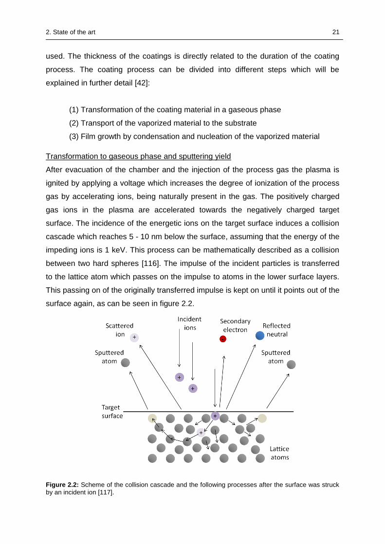
surface. The incidence of the energetic ions on the target surface induces a collision
cascade which reaches 5 - 10 nm below the surface, assuming that the energy of the
impeding ions is 1 keV. This process can be mathematically described as a collision
between two hard spheres [116]. The impulse of the incident particles is transferred
to the lattice atom which passes on the impulse to atoms in the lower surface layers.
This passing on of the originally transferred impulse is kept on until it points out of the
surface again, as can be seen in figure 2.2.
Figure 2.2: Scheme of the collision cascade and the following processes after the surface was struck by an incident ion [117].
2. State of the art 22
An atom of the target is sputtered when its kinetic energy component normal to the
surface is larger than the surface binding energy. This is approximated by the heat of
sublimation for the target bulk material [119]. The sputtered atoms are to a large
extent (approximately 95 %) neutral atoms. If the energy of the impeding particle is
too low (< 5 eV) the particle can also be reflected or adsorbed on the surface [117].
The energy Et that is transferred by the impact is depending on the mass of the
colliding particles (Mi = mass of ion and Mt = mass of target atom) as well as the
angle of incidence and the energy of the striking particle Ei [42]:
2
2
)(
cos4
ti
it
i
t
MM
MM
E
E
(2.1)
The energy transfer reaches its maximum if the masses of the colliding particles are
equal and the angle of incidence is 0°. Argon (Ar) is often used as a sputter gas
because its mass allows effecient sputtering yields and it causes no chemical
reactions with the target surface. In addition it is cheaper than other noble gases
[117]. A higher gas flow of the process gas leads to a higher pressure in the
chamber. On the one hand this leads to an increased sputtering rate because the
amount of ionized atoms in the plasma is increasing. [115]. On the other hand, due to
the higher amount of gas atoms on the way to the substrate also the probability of
collisions between these atoms and the sputtered particles is increasing [114].
The macroscopic parameter that significantly determines the sputtering rate is the
applied sputtering power. The ion current to the target is increasing linearly with
increasing sputtering power. That means that with each striking particle creating on
average the same amount of sputtered atoms the deposition rate is higher, when the
sputtering power is increasing [114]. Another important parameter that describes the
sputtering process is the sputtering yield. The sputtering yield represents the number
of atoms that are sputtered from the target surface per striking particle. Like the
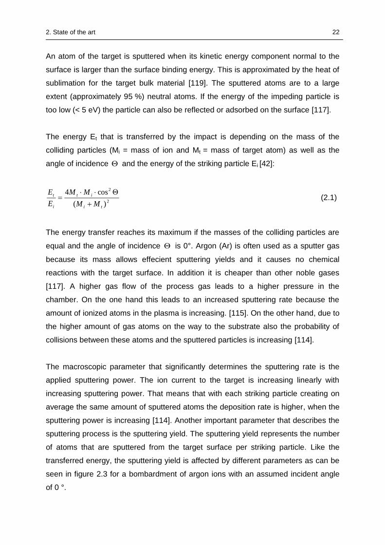
transferred energy, the sputtering yield is affected by different parameters as can be
seen in figure 2.3 for a bombardment of argon ions with an assumed incident angle
of 0 °.
2. State of the art 23
Figure 2.3: Sputtering yield of different target materials depending on the energy of the impeding Ar-ions at normal angle of incidence. Reprinted from [120] with permission from Elsevier Science and Technology Books.
The energy of the striking particles as well as the target material and the mass
coefficients between target atoms and gas ions strongly influence the sputtering yield
and therefore the deposition rate. The different sputtering yields for different materials
must also be considered as a factor that influences the composition of the developing
coating, if e.g. a target consisting of different materials like an alloy, compound or
composite target is used [121], [122], [123], [124].
Transport of the vaporized material to the substrate
The emitted atoms migrate from the target through the chamber towards the
substrate, propelled by the transferred energy they gained from the impeding
sputtering gas ions. The energy spectrum of the ejected particles is in the range of 10
– 40 eV with a Maxwell distribution centered on the most probable energy. The most
probable energy corresponds to half the binding energy of the emitted atoms [116].
The atoms sputtered from the target leave the surface with approximately a cosine
distribution [117]. The gas atoms in the chamber can modify the flux distribution of
the emitted particles by scattering. The amount of scattering through collisions with
gas atoms is increasing with higher pressure in the deposition chamber. These
collisions lead to a thermalization of the ejected particles i.e. decrease in kinetic
2. State of the art 24
energy to the energy of the ambient gas [113]. A lower kinetic energy leads to a lower
mobility of the atoms on the substrate surface which makes it harder to find
energetically favorable adsorption sites [114]. The mean free path gives the average
distance that a particle can move in the gas between collisions with other particles.
Under optimum conditions, i.e. avoiding any collisions with gas atoms, the mean free
path of the ejected particles is longer than the distance from target to substrate,
which can be achieved by keeping the pressure in the chamber as low as possible
[115].
Film growth by condensation and nucleation of the vaporized material
When sputtered particles arrive on the substrate surface different processes can take
place. The particles can be reflected, stay on the surface shortly and re-evaporate
after a residence time or they condense on the surface [42]. The condensation of the
particles does not always occur immediately after initial adsorption. In dependency of
the interaction between substrate surface atoms and the arriving particles they are to
some extent mobile. These so called adatoms diffuse on the surface with a diffusion
velocity depending on their kinetic energy, the interaction with the substrate atoms,
and the temperature of the substrate [113]. The stronger the bonding between
adatom and substrate, the higher is the density of nucleation sites on the substrate
surface [116]. While the adatoms are diffusing on the surface, chemical reactions
with surface atoms, the search for favorable nucleation sites and collisions with other
atoms, which are moving or are adsorbed on the surface, lead to loss of energy. This
process finally ends in the condensation of the adatom by bonding to a surface atom
[113]. Nucleation can also take place when the diffusing atoms collide with other
diffusing atoms and create stable nucleation sites. The density of nucleation sites can
be increased by higher substrate temperature, higher mobility of the adatoms, a
higher deposition rate, and a higher kinetic energy of the arriving particles [113],
[115]. The created nuclei can grow by combination with other adatoms that diffuse on
the surface. If the substrate temperature is high enough to allow atomic diffusion and
rearrangement, an agglomeration of nuclei can occur in order to minimize their
surface area [113].
The last step in the coating process is the growing of the film. The structure and
properties of the developing film are highly influenced by the coating parameters like
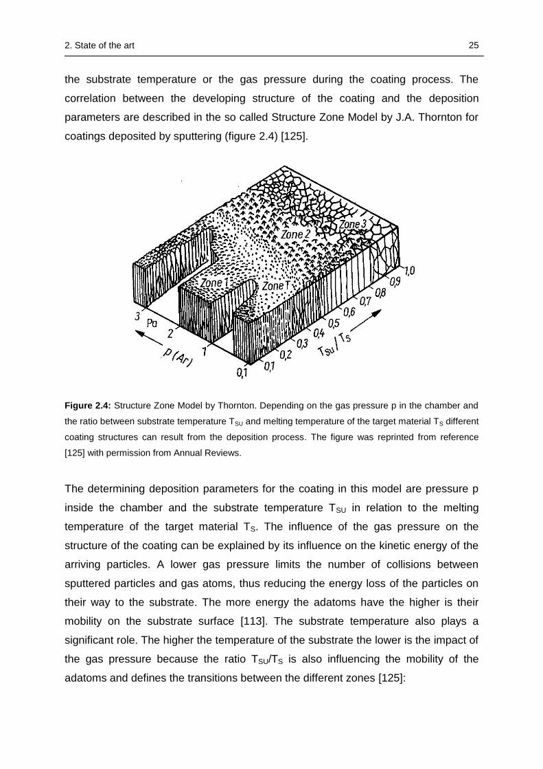
2. State of the art 25
the substrate temperature or the gas pressure during the coating process. The
correlation between the developing structure of the coating and the deposition
parameters are described in the so called Structure Zone Model by J.A. Thornton for
coatings deposited by sputtering (figure 2.4) [125].
Figure 2.4: Structure Zone Model by Thornton. Depending on the gas pressure p in the chamber and
the ratio between substrate temperature TSU and melting temperature of the target material TS different
coating structures can result from the deposition process. The figure was reprinted from reference
[125] with permission from Annual Reviews.
The determining deposition parameters for the coating in this model are pressure p
inside the chamber and the substrate temperature TSU in relation to the melting
temperature of the target material TS. The influence of the gas pressure on the
structure of the coating can be explained by its influence on the kinetic energy of the
arriving particles. A lower gas pressure limits the number of collisions between
sputtered particles and gas atoms, thus reducing the energy loss of the particles on
their way to the substrate. The more energy the adatoms have the higher is their
mobility on the substrate surface [113]. The substrate temperature also plays a
significant role. The higher the temperature of the substrate the lower is the impact of
the gas pressure because the ratio TSU/TS is also influencing the mobility of the
adatoms and defines the transitions between the different zones [125]:
2. State of the art 26
For small ratios of TSU/TS the adatoms have low mobility and hence insufficient
energy to overcome shadowing effects. These effects mean that higher points on the
surface receive more flux than lower ones and so shadowing induces a structure with
open boundaries, that is composed of needle-like crystallites with domed caps [114],
[125]. The low mobility of the atoms results not only in a low surface diffusion but also
the volume diffusion in the layer is very low [117]. Accordingly, this type of structure is
porous and has a lower density because the emerging cavities are not filled while the
film is growing [115].
Higher substrate temperatures lead to the so-called transition zone T: The fiber-like
structures are now more densely packed and the surface is smoother because the
adatoms have sufficient energy to partially overcome the shadowing effects [114],
[125]. The boundary between zone 1 and zone T shifts to higher TSU/TS ratios for
increasing gas pressure [116]. With increasing substrate temperature (approximately
up to TSU/TS < 0.45) the crystallites become bigger and the surface is getting
smoother [114]. If the substrate temperature is high enough, structures of the type of
zone 2 evolve: The higher mobility of the adatoms leads to a dense columnar grain
structure because of surface recrystallization; hence, this phenomenon is also called
surface diffusion controlled growth [126]. At even higher substrate temperatures
(TSU/TS > 0.45) the bulk diffusion controlled structures of zone 3 evolve: Atoms now
have sufficient energy to diffuse inside the growing layer and find energetically
favorable and more stable positions. Recrystallization occurs and the grains grow
bigger. The evolving dense coating has very low porosity and a smooth surface [117],
[125]. In addition to the higher mobility of the adatoms the rising substrate
temperature is also decreasing the desorption rate and at the same time increasing
the nucleation rate [127].
By applying a negative bias voltage to the substrate holder positively charged plasma
gas ions are accelerated towards the substrate during deposition of the coating. This
leads to a continuous bombardment of the evolving coating by gas ions. On the one
hand impurities or loosely bound atoms can be resputtered. On the other hand the
impinging ions transfer their energy to the atoms of the coating and can enhance
their mobility on the surface [114], [127].
2. State of the art 27
2.3 Biomedical applications of PVD coatings
Coating by physical vapour deposition is a very versatile technique and many studies
have been conducted trying to improve tissue compatibility and provide safe long-
term service of metallic biomaterials. As wear and corrosion resistance is one of the
major issues regarding metallic biomaterials, improvement of these material
properties has been a basic goal in the research of physical vapour deposition on
metallic biomaterials. However, according to Hanawa, surface treatment techniques
can be used to improve the tissue compatibility and performance of the surface layer
in different ways including the inhibition of biofilm formation, improving bone
formation and bone bonding, or even the inhibition of bone formation, as well as the
improved adhesion of soft tissue and blood compatibility [41].
In the end of the 1980s the first experiments with a dense TiN coating obtained by
physical vapour deposition were conducted with a designed application in the
medical field [39]. These coatings created by arc evaporation should serve as a
protection against abrasion and corrosion on femoral components for Ti-6Al-4V total
hip replacements (THR) and total knee replacements (TKR) [128], [129]. These early
studies could show an improvement of abrasion resistance and decreased wear of
the polyethylene counterparts due to the lower friction and good chemical stability of
the TiN layer. One of the first patents on PVD coatings for biomedical applications
was also granted for TiN coatings [130]. However, a number of in vivo studies that
were conducted with TiN coated implants afterwards could not confirm the good
results obtained during the test in the laboratory and demanded further investigation,
particularly regarding the wear resistance and delamination behavior of this
biomaterial modification [131], [132]. In other studies on femoral heads retrieved from
revision surgeries, the coatings were also found to be inadequate for these
applications and it was stated their use should not be advocated [133]. Other hard
ceramic coatings produced by physical vapour deposition that were early investigated
for enhanced corrosion and wear resistivity of THR and TKR, were silicon carbide
(SiC), aluminum oxide (Al2O3), and diamond like carbon (DLC) [134], [135]. Load
bearing model implants of cobalt-chrome alloys coated by physical vapour deposition
with amorphous DLC showed significantly poorer frictional and wear performance
than uncoated surfaces of CoCr [136]. In these tests, where the in vivo motion of the
2. State of the art 28
knee was simulated by sliding the coated and uncoated surfaces against UHMWPE,
a potential benefit from the coatings against abrasion was negated. Thull stated in
2003 that it is difficult to realize hard implant coatings by means of PVD on the
moving load bearing parts of applications as in knee and hip implants because of
their limited adhesion, but PVD coatings could be useful on the fixational parts of
these implants [137]. Thull therefore proposed that the quality of PVD coatings must
be evaluated regarding the coating method and used coating parameters, the surface
preparation before the coating as well as the application site and the duration of
service of the coated implant.
Since these early studies, the number of investigated material systems for biomedical
applications realized by PVD methods increased a lot, as well as the number of
different commercially established applications of PVD coatings. As indicated by the
introducing part of this section, wear and corrosion resistance are a very important
research topic in the surface modification of metallic biomaterials by PVD methods,
which has been addressed by hard implant coatings like TiN. However, in many
cases, coatings are designed to fulfill more than just a mechanically protective
function for the implants.
Biofunctionalization is often a desired aim for biomaterials, but the incorporation of
bioactive species like proteins and growth factors into the coating itself is
complicated, if not completely incompatible in the case of PVD processes. The
applied PVD techniques often require increased temperatures, and therefore the
functionalization can only be realized after the coating process. Further
disadvantages of protein modification are besides high costs the required conditions
of sterilization and storage of the functionalized materials.
Regarding these aspects, the insertion of low doses of metal ions into implantable
materials provides a promising alternative method to improve implant healing and
achieve controlled guidance of implant-specific tissue reactions (e.g. zinc (Zn),
calcium (Ca), silicon (Si)) or provide antimicrobial properties (Ag, Cu, Zn) which in the
case of polymers, ceramic scaffolds or cements can be provided via the addition of
the respective soluble salts [138], [139], [140], [141], [142]. The improvement of
implant performance by surface modifications with additional metal ions is also a
suitable strategy for PVD coatings, since the incorporation of metal ions is
2. State of the art 29
comparably easy to achieve by the simultaneous usage of different sources of metal
vapour.
This strategy is frequently examined to equip the coatings e.g. with additional
antimicrobial properties. For this reason, known antibacterial agents such as silver or
copper are incorporated in a matrix of titanium nitride (TiN), tantalum nitride (TaN) or
zirconium nitride (ZrN). This can either be done by reactive co-sputtering of Ti, Ta, Zr
with Ag or Cu in nitrogen atmosphere or by using hybrid coating methods such as the
arc evaporation of titanium with simultaneous sputtering of silver [143], [144], [145],
[146]. In these studies it could be demonstrated that the hard coatings functionalized
with metal ions were highly effective against bacteria such as St. aureus, St.
epidermidis or E. coli. Reactive co-sputtering of different targets could also be used
to create combinations of Ag and Cu inside a TaN matrix, thereby increasing the
spectrum of bactericidal activity [147]. However, these coatings often exhibit their
complete antibacterial potential only after a suitable annealing step, when the volume
diffusion of silver or copper out of the matrix leads to the formation of nanoparticles
on the surface of the coatings. The enrichment of soft metals on the surface has
another positive effect, as they have shown to act as a kind of lubricant when the
coatings are exposed to wear [147].
In order to increase bone formation and bonding strength of metallic implants to
surrounding bone, depositions of calcium phosphates (CAPs) such as hydroxyapatite
(HA) are frequently examined coating materials, that could also be deposited in the
form of thin films by PVD methods [148], [149]. The application of movable target
shutters over joined targets of Ti and HA could even be used to create composition
gradients of Ti and HA, thereby increasing the adhesion of the ceramic coatings to
the Ti substrate [148]. Using PVD methods not only calcium phosphate ceramic
coatings like HA can be deposited to increase the bonding strength between the
implant and bone: deposition of TiO2 on substrates of titanium and stainless steel via
PVD methods has also shown to improve the bone bonding abilities while
simultaneously improving the corrosion resistance of the substrate materials [150],
[151]. As already mentioned in the introduction, the deposition of tantalum is also an
auspicious approach to increase the bone bonding ability as well as corrosion
resistance of metallic biomaterials, since its high cost, high density and extremely
high melting temperature are limiting its application in larger medical devices. The
2. State of the art 30
biocompatibility and osteoconductive potential of Ta bulk materials is well known, and
also the beneficial potential of Ta coatings deposited by methods such as laser
deposition could already be demonstrated and has found to be equivalent to
RF-sputtered HA coatings in in vitro tests, but with the additional advantage of
significantly improved bonding strength between coating and Ti substrate [12],[43]. In
accordance to previous studies using Ta, also Ta coatings deposited by sputtering
showed beneficial influence on osteogenically stimulated human mesenchymal stem
cells (hMSCs) [152]. Another interesting feature of magnetron sputtered double
layers of Ta and Ta oxide could be demonstrated by Macionczyk et al.: Film cracks in
the oxide layer that were generated by the plastic deformation of the stainless
substrates were closed due to the fast oxidation in physiological saline solution [44].
This effect was attributed to the volume increase from metallic Ta to Ta oxide.
Another interesting coating material for biomedical applications in contact to bone,
mainly for the same reasons as tantalum, is niobium. Sputtered Nb coatings have
already shown promising results in in vitro tests [153]. Next to pure metals, the
simultaneous usage of different metal targets also allows the deposition of
biomedically relevant alloys such as Ti alloys e.g. TiNbZr that are interesting as
implant coatings in contact to bone [154].
Where materials such as CaPs, tantalum or niobium are deposited to improve the
bonding between the implant and surrounding bone it could also be shown that it is in
some cases beneficial to avoid strong bonding to the surrounding tissue, as in the
case of retrievable medical devices, e.g. fixators like bone nails and bone screws
[41]. This could be demonstrated via the deposition of pure Zr layers that prevented
the formation of calcium phosphates on the surface and thereby inhibited the
assimilation of the Ti alloy substrates with bone [27].
Apart from applications in hard tissue replacements PVD coatings are highly
investigated for implants in contact with soft tissue or blood, e.g. serving as surface
modifications for cardiovascular stents. The specific requirements for coatings
designed for applications in contact with blood are different to coatings designed for
service in orthopedic applications. Osseointegration is no longer the deciding factor,
and the main focus for stent materials has been shifted to hemocompatibility, the
prevention of blood clotting and platelet adhesion/activation as well as the avoidance
of restenosis, the narrowing of the blood vessel subsequent to stent implantation
2. State of the art 31
[155], [156]. Although the application is very different, some of the materials are quite
similar to coatings on orthopedic materials. Coatings of titanium nitride oxide (TiNOX)
on stents made from stainless steel have shown very promising results in in vitro as
well as in vivo tests, with the coatings fabricated by deposition of titanium in a
process gas mixture of oxygen and nitrogen [157], [158]. Also PVD coatings of
tantalum on nitinol (NiTi) stents could increase the hemocompatibility of the stent and
have shown to effectively inhibit the release of Ni ions from the stent substrate [159].
Furthermore, the Ta coatings could simultaneously improve the radiopacity of the
stent, rendering it easier to locate under X-ray control. However also materials are
applied that could not be used in orthopedic applications, e.g. iridium oxide (IrOx)
deposited by reactive sputtering on a previously gold-plated stainless steel stent
[160]. On the one hand, iridium oxide coatings can act as a diffusion barrier for metal
ions eluded from the stent material and improve the corrosion resistance of the
stents, which are often made from nitinol or stainless steel [161]. On the other hand
this material exhibits a catalytic effect against hydrogen peroxide (H2O2) and may
disrupt the restenosis process as H2O2 is inhibiting the growth of endothelial cells and
has a stimulating effect on the proliferation of smooth muscle cells [160], [162].
Coating techniques such as physical vapour deposition are gaining more and more
interest in the field of biomaterials, particularly since it became evident during the last
decade that nanotopographies can significantly influence the cellular and bacterial
behavior on the implant surface [163]. Therefore apart from pure mechanical or
chemical reasons the focus is directed towards modifying surface properties like
nanoroughness and surface energy that can be controllably manipulated by PVD
methods.
2.4 Nanotube formation by anodisation
2.4.1 Synthesis of nanotube arrays by electrochemical anodization
In the wake of the successful synthesis of carbon nanotubes in 1991 there was
intensive research on the fabrication of nanotubular structures [164]. Inspired by an
increasing variety of application possibilities there was huge interest to transfer this
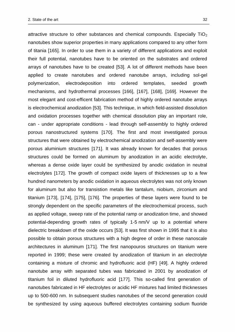
2. State of the art 32
attractive structure to other substances and chemical compounds. Especially TiO2
nanotubes show superior properties in many applications compared to any other form
of titania [165]. In order to use them in a variety of different applications and exploit
their full potential, nanotubes have to be oriented on the substrates and ordered
arrays of nanotubes have to be created [53]. A lot of different methods have been
applied to create nanotubes and ordered nanotube arrays, including sol-gel
polymerization, electrodeposition into ordered templates, seeded growth
mechanisms, and hydrothermal processes [166], [167], [168], [169]. However the
most elegant and cost-efficent fabrication method of highly ordered nanotube arrays
is electrochemical anodization [53]. This technique, in which field-assisted dissolution
and oxidation processes together with chemical dissolution play an important role,
can - under appropriate conditions - lead through self-assembly to highly ordered
porous nanostructured systems [170]. The first and most investigated porous
structures that were obtained by electrochemical anodization and self-assembly were
porous aluminium structures [171]. It was already known for decades that porous
structures could be formed on aluminum by anodization in an acidic electrolyte,
whereas a dense oxide layer could be synthesized by anodic oxidation in neutral
electrolytes [172]. The growth of compact oxide layers of thicknesses up to a few
hundred nanometers by anodic oxidation in aqueous electrolytes was not only known
for aluminum but also for transistion metals like tantalum, niobium, zirconium and
titanium [173], [174], [175], [176]. The properties of these layers were found to be
strongly dependent on the specific parameters of the electrochemical process, such
as applied voltage, sweep rate of the potential ramp or anodization time, and showed
potential-depending growth rates of typically 1-5 nm/V up to a potential where
dielectric breakdown of the oxide occurs [53]. It was first shown in 1995 that it is also
possible to obtain porous structures with a high degree of order in these nanoscale
architectures in aluminum [171]. The first nanopouros structures on titanium were
reported in 1999; these were created by anodization of titanium in an electrolyte
containing a mixture of chromic and hydrofluoric acid (HF) [49]. A highly ordered
nanotube array with separated tubes was fabricated in 2001 by anodization of
titanium foil in diluted hydrofluoric acid [177]. This so-called first generation of
nanotubes fabricated in HF electrolytes or acidic HF mixtures had limited thicknesses
up to 500-600 nm. In subsequent studies nanotubes of the second generation could
be synthesized by using aqueous buffered electrolytes containing sodium fluoride
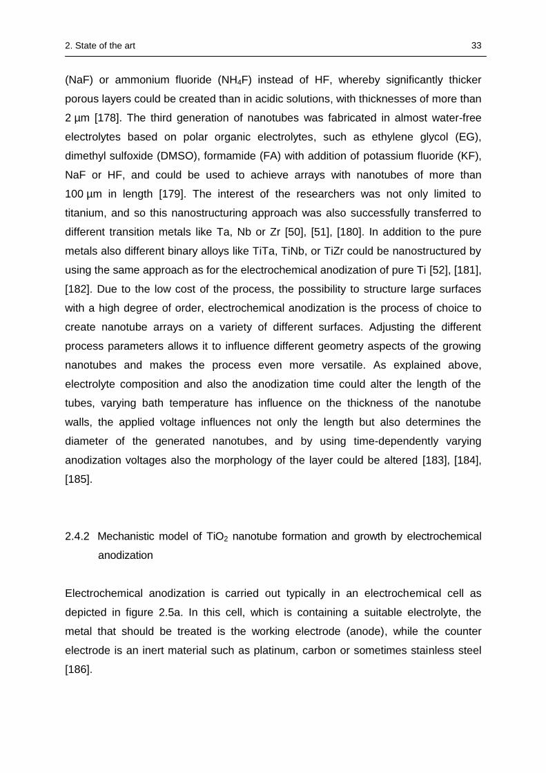
2. State of the art 33
(NaF) or ammonium fluoride (NH4F) instead of HF, whereby significantly thicker
porous layers could be created than in acidic solutions, with thicknesses of more than
2 µm [178]. The third generation of nanotubes was fabricated in almost water-free
electrolytes based on polar organic electrolytes, such as ethylene glycol (EG),
dimethyl sulfoxide (DMSO), formamide (FA) with addition of potassium fluoride (KF),
NaF or HF, and could be used to achieve arrays with nanotubes of more than
100 µm in length [179]. The interest of the researchers was not only limited to
titanium, and so this nanostructuring approach was also successfully transferred to
different transition metals like Ta, Nb or Zr [50], [51], [180]. In addition to the pure
metals also different binary alloys like TiTa, TiNb, or TiZr could be nanostructured by
using the same approach as for the electrochemical anodization of pure Ti [52], [181],
[182]. Due to the low cost of the process, the possibility to structure large surfaces
with a high degree of order, electrochemical anodization is the process of choice to
create nanotube arrays on a variety of different surfaces. Adjusting the different
process parameters allows it to influence different geometry aspects of the growing
nanotubes and makes the process even more versatile. As explained above,
electrolyte composition and also the anodization time could alter the length of the
tubes, varying bath temperature has influence on the thickness of the nanotube
walls, the applied voltage influences not only the length but also determines the
diameter of the generated nanotubes, and by using time-dependently varying
anodization voltages also the morphology of the layer could be altered [183], [184],
[185].
2.4.2 Mechanistic model of TiO2 nanotube formation and growth by electrochemical
anodization
Electrochemical anodization is carried out typically in an electrochemical cell as
depicted in figure 2.5a. In this cell, which is containing a suitable electrolyte, the
metal that should be treated is the working electrode (anode), while the counter
electrode is an inert material such as platinum, carbon or sometimes stainless steel
[186].
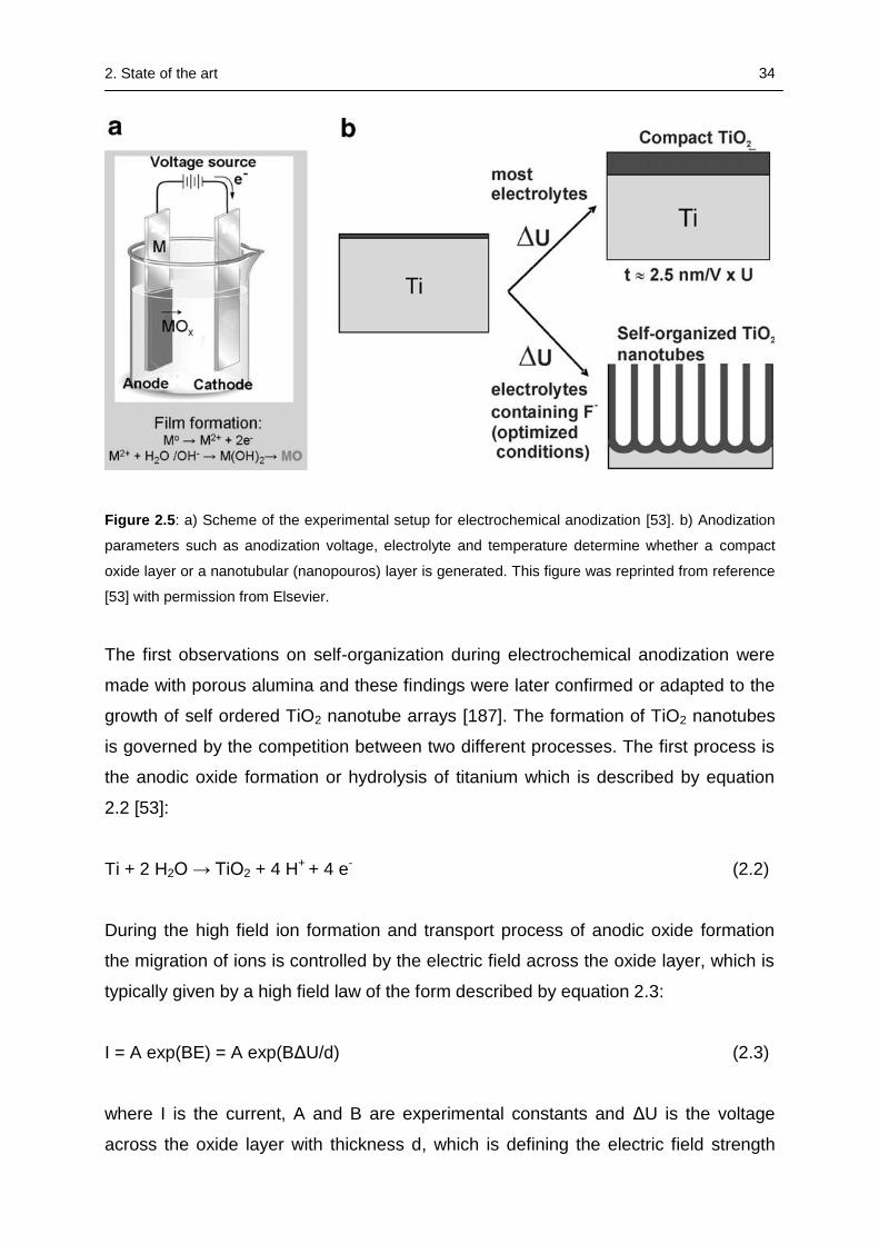
2. State of the art 34
Figure 2.5: a) Scheme of the experimental setup for electrochemical anodization [53]. b) Anodization
parameters such as anodization voltage, electrolyte and temperature determine whether a compact
oxide layer or a nanotubular (nanopouros) layer is generated. This figure was reprinted from reference
[53] with permission from Elsevier.
The first observations on self-organization during electrochemical anodization were
made with porous alumina and these findings were later confirmed or adapted to the
growth of self ordered TiO2 nanotube arrays [187]. The formation of TiO2 nanotubes
is governed by the competition between two different processes. The first process is
the anodic oxide formation or hydrolysis of titanium which is described by equation
2.2 [53]:
Ti + 2 H2O → TiO2 + 4 H+ + 4 e- (2.2)
During the high field ion formation and transport process of anodic oxide formation
the migration of ions is controlled by the electric field across the oxide layer, which is
typically given by a high field law of the form described by equation 2.3:
I = A exp(BE) = A exp(BΔU/d) (2.3)
where I is the current, A and B are experimental constants and ΔU is the voltage
across the oxide layer with thickness d, which is defining the electric field strength
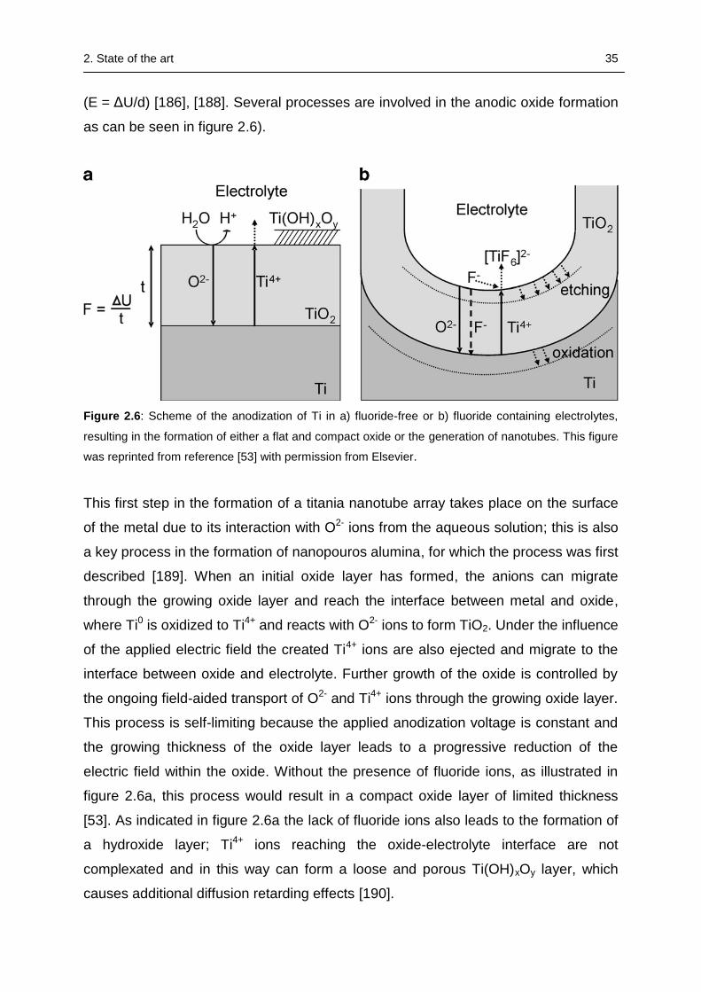
2. State of the art 35
(E = ΔU/d) [186], [188]. Several processes are involved in the anodic oxide formation
as can be seen in figure 2.6).
Figure 2.6: Scheme of the anodization of Ti in a) fluoride-free or b) fluoride containing electrolytes,
resulting in the formation of either a flat and compact oxide or the generation of nanotubes. This figure
was reprinted from reference [53] with permission from Elsevier.
This first step in the formation of a titania nanotube array takes place on the surface
of the metal due to its interaction with O2- ions from the aqueous solution; this is also
a key process in the formation of nanopouros alumina, for which the process was first
described [189]. When an initial oxide layer has formed, the anions can migrate
through the growing oxide layer and reach the interface between metal and oxide,
where Ti0 is oxidized to Ti4+ and reacts with O2- ions to form TiO2. Under the influence
of the applied electric field the created Ti4+ ions are also ejected and migrate to the
interface between oxide and electrolyte. Further growth of the oxide is controlled by
the ongoing field-aided transport of O2- and Ti4+ ions through the growing oxide layer.
This process is self-limiting because the applied anodization voltage is constant and
the growing thickness of the oxide layer leads to a progressive reduction of the
electric field within the oxide. Without the presence of fluoride ions, as illustrated in
figure 2.6a, this process would result in a compact oxide layer of limited thickness
[53]. As indicated in figure 2.6a the lack of fluoride ions also leads to the formation of
a hydroxide layer; Ti4+ ions reaching the oxide-electrolyte interface are not
complexated and in this way can form a loose and porous Ti(OH)xOy layer, which
causes additional diffusion retarding effects [190].
2. State of the art 36
The second process in the formation of nanotubes, the chemical dissolution of TiO2,
described by equation 2.4, takes place in the presence of fluoride ions [165]:
TiO2 +6F- + 4H+ → [TiF6]2− + 2H2O (2.4)
Building up ordered nanotubular structures is only possible when high field conditions
are created and maintained, which means that there is equilibrium between the
formation and dissolution of the oxide layer. This can only be achieved if the steady
state oxide is thin enough to allow permanent migration of ions. Therefore a certain
degree of solubility of the oxide in the electrolyte is a prerequisite for the continuous
ordered oxide growth [186]. In the case of titania this can be achieved by adding a
suitable agent such as fluoride ions to the electrolyte which influence the formation
process considerably in two ways: first, these ions can form water soluble [TiF6]2−
complexes that lead to a permanent chemical attack of formed TiO2; second, they
prevent the formation of a Ti(OH)xOy layer due to their direct complexation of Ti4+
ions arriving at the oxide-electrolyte interface as described by equation 2.5 [53]:
Ti4+ + 6F- → [TiF6]2− (2.5)
The resulting current-time-curves strongly depend on the concentration of fluoride
ions in the electrolyte; in consequence, three different cases can be distinguished for
varying oxide solubility in the electrolyte. In the first case a stable and insoluble
compact oxide layer will form if the concentration of F- is below a critical value; the
resulting curve will be quite similar to the current-transient in an electrolyte containing
no fluoride ions. In the second case no oxide layer will form if the F- concentration is
too high and ions formed by metal oxidation will be immediately solvatized by the
abundance of fluoride ions; this results in a process described as active corrosion or
electropolishing. In the third case, a moderate concentration of fluoride ions - typically
in the range of 0.05-0.5 wt% - leads to the establishment of a steady state situation in
the competition between dissolution and formation of oxide and can result in the
formation of porous oxide [191]. The presence of an optimized concentration of
fluoride ions in the electrolyte leads to a range of oxide dissolution and formation
which makes it possible to create highly self-organized oxide pore arrangements or
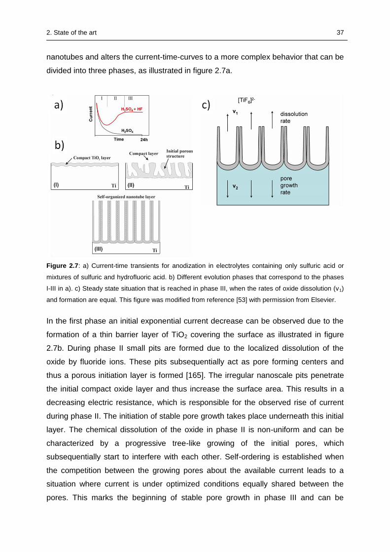
2. State of the art 37
nanotubes and alters the current-time-curves to a more complex behavior that can be
divided into three phases, as illustrated in figure 2.7a.
Figure 2.7: a) Current-time transients for anodization in electrolytes containing only sulfuric acid or
mixtures of sulfuric and hydrofluoric acid. b) Different evolution phases that correspond to the phases
I-III in a). c) Steady state situation that is reached in phase III, when the rates of oxide dissolution (v1)
and formation are equal. This figure was modified from reference [53] with permission from Elsevier.
In the first phase an initial exponential current decrease can be observed due to the
formation of a thin barrier layer of TiO2 covering the surface as illustrated in figure
2.7b. During phase II small pits are formed due to the localized dissolution of the
oxide by fluoride ions. These pits subsequentially act as pore forming centers and
thus a porous initiation layer is formed [165]. The irregular nanoscale pits penetrate
the initial compact oxide layer and thus increase the surface area. This results in a
decreasing electric resistance, which is responsible for the observed rise of current
during phase II. The initiation of stable pore growth takes place underneath this initial
layer. The chemical dissolution of the oxide in phase II is non-uniform and can be
characterized by a progressive tree-like growing of the initial pores, which
subsequentially start to interfere with each other. Self-ordering is established when
the competition between the growing pores about the available current leads to a
situation where current is under optimized conditions equally shared between the
pores. This marks the beginning of stable pore growth in phase III and can be
2. State of the art 38
observed by an almost constant current level which is due to the establishment of the
steady-state situation between oxide formation and dissolution (see fig. 2.7c) [186].
Under high field conditions in this steady state, oxide is continuously formed and
dissolved at the bottom of the tubes. This results in a thinner oxide and therefore
higher electric field at the bottom which enhances further migration of ions through
the barrier layer [191]. One particular role of fluoride ions is thus to maintain a thinner
bottom oxide layer by chemical etching of the barrier layer and permanent
complexation of the Ti4+ ions arriving at the oxide–electrolyte interface [192].
The second role in which fluoride ions influence the nanotube formation is due to
their small ionic radius. Under the influence of the constant electric field, their small
ionic radius allows them to migrate through the forming oxide layer and hence to
compete with the transportation of O2-. It has been observed that the fluoride ions
migrate much faster through the oxide layer than the O2- ions which results in the
formation of a fluoride-rich layer at the metal-oxide interface [193], [194]. This fluoride
rich layer is believed to be the origin of the nanotube separation and responsible for
the transition from a porous to a tubular structure [186]. As the nanotube layer is
continually moving “inwards” through the titanium substrate in its steady state, that is
established when the pore growth rate at the metal-oxide interface is identical to the
thickness reducing pure chemical dissolution rate of the oxide at the outer interface,
the fluoride species at the metal oxide interface will be pushed towards the
boundaries between the pores [53]. This effect can be explained by the so-called
plastic flow model which assumes that the combination of compressive stresses and
electrostrictive forces during nanotube growth, together with the substantial ionic
movement in the high electric field, induces some plasticity in the barrier layer (see
fig. 2.8) [195], [196].
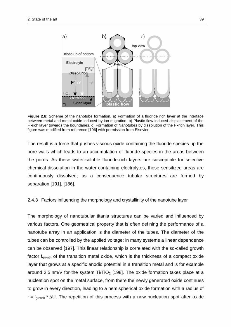
2. State of the art 39
Figure 2.8: Scheme of the nanotube formation. a) Formation of a fluoride rich layer at the interface between metal and metal oxide induced by ion migration. b) Plastic flow induced displacement of the F
--rich layer towards the boundaries. c) Formation of Nanotubes by dissolution of the F
--rich layer. This
figure was modified from reference [196] with permission from Elsevier.
The result is a force that pushes viscous oxide containing the fluoride species up the
pore walls which leads to an accumulation of fluoride species in the areas between
the pores. As these water-soluble fluoride-rich layers are susceptible for selective
chemical dissolution in the water-containing electrolytes, these sensitized areas are
continuously dissolved; as a consequence tubular structures are formed by
separation [191], [186].
2.4.3 Factors influencing the morphology and crystallinity of the nanotube layer
The morphology of nanotubular titania structures can be varied and influenced by
various factors. One geometrical property that is often defining the performance of a
nanotube array in an application is the diameter of the tubes. The diameter of the
tubes can be controlled by the applied voltage; in many systems a linear dependence
can be observed [197]. This linear relationship is correlated with the so-called growth
factor fgrowth of the transition metal oxide, which is the thickness of a compact oxide
layer that grows at a specific anodic potential in a transition metal and is for example
around 2.5 nm/V for the system Ti/TiO2 [198]. The oxide formation takes place at a
nucleation spot on the metal surface, from there the newly generated oxide continues
to grow in every direction, leading to a hemispherical oxide formation with a radius of
r = fgrowth * U. The repetition of this process with a new nucleation spot after oxide
2. State of the art 40
breakdown at the bottom of the pores would then lead to a growth factor and voltage-
dependent tube diameter [187]. That the hemispherical or rounded shape of the tube
bottom is maintained can also be explained by three different factors influencing the
nanotube growth [197]. According to equation 2.2, the anodization process creates
local acidification at the tube bottom due to the oxidation and hydrolysis of titanium,
which may lead to enhanced chemical dissolution at the pore tip, as the dissolution
rate of TiO2 is highly dependent on the pH value [199]. Another crucial factor is the
intrinsic compressive stress that is generated at the interface due to the conversion of
metal to oxide, leading to a volume expansion which is given by the Pilling-Bedworth
ratio (PBR =volume of the oxide to the volume of the metal, for TiO2/Ti = 2.43) [49].
Furthermore, once the interface curvature and oxide dissolution at the pore bottom
have started, distinct spots like the pore tip will show enhanced dissolution due to the
local concentration of electric field lines [187].
The thickness of the nanotube layer and therefore the length of the nanotubes
linearly increase with anodization time, assuming that other parameters are being
kept constant. But this growth in length is limited to a point where the steady state
condition is reached and no further growing in the thickness of the layer is observed
[186]. The competition between oxide formation at the bottom and continuous
chemical dissolution of the top of the tubes results in a typical V-shaped profile of the
inner part of the walls. This profile evolves, because the upper and earlier-formed
part of the walls is being exposed to the fluoride containing etching electrolyte for a
longer time; hence, enhanced thinning of the top compared to the bottom part of the
walls can be observed [53]. One of the most important factors influencing tube
morphology, particularly length and diameter of the tubes, but also the regularity of
the generated nanotube layer is the composition of the electrolyte. In aqueous
electrolytes typically nanotubes with a diameter between 10 and 100 nm can be
formed by application of voltages in the range of 5-25 V and with a concentration of
fluoride ions between 0.05-0.5 wt% [186]. Lower voltages usually lead to a
nanopouros structure as it can be observed in alumina, whereas at higher voltages
the nanotubular structure is replaced by a sponge-like non-organized porous
structure. This can be explained by a weakening of the Ti–O bond due to polarization
in the strong electric field, thus promoting further dissolution of the metal oxide [170].
Due to the overall low pH value, acidic aqueous-fluoride-containing electrolytes
usually show a very high chemical etching rate of titanium oxide. In this case the
2. State of the art 41
steady state situation is reached after a shorter anodization time, which results in a
reduced thickness of the nanotubular layer. After reaching this steady state,
extended anodization times do not result in longer tubes, but in nanotubular
structures more uniform in both shape and size [165]. Usually layers of only a few
hundred nanometers in thickness can be obtained when using e.g. mixtures of HF
with acetic (~ 400 nm) or sulfuric acid (~ 500 nm). [200], [201]. An exception seem to
be nanotubular layers fabricated in a mixture of phosphoric and hydrofluoric acid,
where thicknesses of more than 1 µm could be achieved [202]. One possibility of
increasing the length of the tubes in acidic electrolytes without changing their inner
diameter is by decreasing the temperature of the anodizing bath, which leads to a
slower dissolution rate [183]. An additional effect of the decreasing temperature and
dissolution rate is the increasing thickness of the tube walls which is accompanied by
a filling of the areas between the tubes even to a point where all the tubes are
connected and converting the tubular into a nanopouros structure [203].
The limited length of nanotubes obtained by anodization in HF containing aqueous
electrolytes is based on the high dissolution rate at the top of the layer. Hence, in
order to obtain thicker layers and increasing the length of the nanotubes, the
dissolution rate has to be adjusted by using less acidic or even neutral electrolytes
[197]. The pH value of the electrolyte influences the nanotube formation in two ways.
An increasing pH value results in an increasing rate of electrochemical etching due to
the increasing hydrolysis rate and in turn a decreasing rate of chemical dissolution,
which makes it possible to obtain longer nanotubes [170]. By applying a neutral type
of electrolyte, e.g. 1M Na2SO4 solution with addition of 0.1-1 wt% NaF, the
dissolution rate at the bottom of the tubes could be increased while the dissolution
rate at the top of the tubes is decreased. Thereby, nanotubes with a much higher
aspect ratio, i.e. tubes with diameters of 90-110 nm grown to a length up to 2.4 µm,
can be obtainend. This can be achieved by creating a pH gradient from low values at
the bottom of the tube where the oxidation and hydrolysis of titanium creates
localized acidification, to higher values at the tube mouth due to migration and
diffusion effects of the buffer species. This pH gradient provides enhanced
dissolution at the bottom, where the pH value is the lowest, while the walls and top of
the tubes are considerably less attacked due to the higher pH values [178]. With
another approach of this so called 2nd generation synthesis of nanotubes even longer
nanotubes up to 4.5 µm could be fabricated by using electrolytes with higher pH
2. State of the art 42
values (pH 3-5), and a system that is additionally buffered to control the pH value.
The desired pH value was obtained by mixtures of H2SO4, NaOH, NaHSO4 and citric
acid with additions of KF or NaF [184]. Adjusting the dissolution rate using
electrolytes with higher pH values causes the dissolution rate to be higher at the
bottom than at the top. In contrast to nanotube fabrication in strong acidic
electrolytes, this makes the length of the nanotubes much more dependent on the
duration of the process; and anodization times can take up to 90 h for nanotubes of
several micrometers length [165].
Chemical dissolution can even be further decreased by performing electrochemical
anodization in organic electrolyte/F- mixtures based on ethylene glycol or glycerol
with fluoride containing species such as KF, NaF or NH4F [204], [179]. The water
content of the electrolyte affects both growth and etching rate and so it has a double
function as it is required for the oxide formation at the tube bottom but also enhances
the dissolution of the formed nanotube layer [191]. The basic concept behind these
electrolytes of the 3rd generation is to minimize the water content in the electrolytes in
order to reduce the availability of oxygen. This reduces the speed of chemical
dissolution and so linear growth behavior of the nanotubes can be significantly
extended, with nanotubes arrays grown to lengths of more than 100 µm [170], [179].
The diameter of these nanotubes is still linearly dependent on the applied voltage,
but arrays can be grown in a bigger potential range (typically 10-60 V) due to the
lower conductivity of the organic electrolytes [191]. Two very interesting features
should also be mentioned that can only be observed in organic electrolytes with low
water content. Nanotubes grown in organic electrolytes can have smooth walls in
contrast to the rippled walls of nanotubes grown in aqueous electrolytes [204].
The existence of these ripples on the outer surface of the tube walls is attributed to a
competition between the speed of the tube growth and the dissolution rate of the
fluoride-rich watersoluble areas between the tubes. Due to the much lower
dissolution rate of these cell boundaries in electrolytes with low water content,
smooth walls and highly ordered nanotube arrays can be obtained [205]. For
extremely low water contents even nanopouros structures (i.e. no separated tubes)
could be observed due to the insolubility of the areas between the pores in the used
anodization electrolyte [206].
Independent of the used electrolyte, the as-anodized TiO2 nanotubes arrays usually
are amorphous. An additional annealing step performed under oxidizing conditions in
2. State of the art 43
air or O2-atmosphere can convert the nanotubes into anatas or rutile, depending on
the temperature [191]. The nanotubes maintain their amorphous phase until around
250 °C, while beginning conversion of the nanotubes into anatas can be observed by
XRD measurements at temperatures between 250 and 280 °C [165]. Increasing the
temperature leads to an enhanced formation of anatas structure until at 500 °C the
beginning of conversion to rutile phase can be observed. Further increase of the
temperature leads to a reduction of anatas and an increase of the rutile phase [207].
Annealing has an additional effect on the composition of the nanotubes as fluoride
species that are incorporated in the tubes during the anodization process can be
driven out to a large extent. The fluorine concentration is therefore negligible when
the nanotube arrays are heated at temperatures above 400 °C [208]. This is
extremely important with respect to the adhesion of the nanotube layers to the metal
substrate, as the fluoride-rich barrier layers decrease the adhesion of the anodized
layers [193]. Annealing can also have an influence on the morphology of the
nanotubes. TiO2 nanotubes are usually stable up to a temperature of around 580 °C
without noticeable changes in wall thickness or pore diameter [165]. Higher
temperatures lead to collapsing of the nanostructures due to the rutile formation on
titanium by thermal oxidation. The finally emerging protrusions of rutile that come out
of the porous structure at around 550-580 °C are considered to be the principal
cause of collapse of the NTs [209].
2.5 Biomedical applications and cell interactions of TiO2
nanotubes
As described in the previous sections, titanium is one of the most frequently used
materials for biomedical applications. Topography and surface roughness together
with chemical composition are important aspects in the integration of biomaterials:
hence, surface modifications, particularly in the nanoscale regime, have gained a lot
of attention during the last years [210], [163], [211]. Nanotubular TiO2 structures are
promising biomaterials for tissue regeneration since they have topographical features
on the same nanoscale as biomolecules, proteins, enzymes and extra cellular matrix,
etc. [212]. Electrochemical anodization is a very cost effective, controllable and easy
method to structure titanium surfaces on the nanoscale without the need of
expensive equipment as in the case of lithography. Therefore, it is a highly interesting
2. State of the art 44
technique to study biomedical effects and interactions of biologically relevant species
such as cells, bacteria or proteins with materials that exhibit structural features in the
nano-regime [191]. Another advantage of applying this process is the wide range in
which the diameter of the nanotubes can be varied by the applied anodization
voltage, from very small like 10 nm to very large nanostructures of over 200 nm [186].
The self-assembly based process makes it also possible to nanostructure more
complex-shaped surfaces; hence, the technique is also suitable for the surface
modification of biomedical devices like stents, dental-implant screws or hip-implants
[191].
One interesting biomedical effect of TiO2 nanotubes apart from the interaction with
living matter is the enhanced hydroxyapatite formation during immersion in simulated
body fluid (SBF), which is an important feature of TiO2 nanotubular structures for their
potential success as biomedical devices, especially in contact to bone [213]. It could
also be shown that the crystallographic form of TiO2 is an important factor for the
formation of apatite. Nanotube layers that were annealed to anatase or anatase-rutile
mixtures exhibit even more efficient apatite formation than amorphous structures.
Further improvement of hydroxyapatite growth can be achieved with additional
chemical treatments either with NaOH or by pre-loading with synthetic hydroxyapatite
[214], [215].
One of the first papers on the topic of cell interaction with TiO2 nanotubes of different
diameter was published in 2007, where a significant influence of the nanotopography
on mesenchymal stem cells (MSC from Lewis rats) could be demonstrated [216].
Small nanotubes with 15 nm diameters enhanced cell adhesion, differentiation and
proliferation, whereas larger diameters of about 100 nm induced cell death, which
was explained by lacking adhesion sites for the cells on the larger nanotube
diameter. The same group demonstrated in 2009 similar size effects for other cells
such as human osteoblast-like cells (hOBs) in this diameter range and could confirm
the best response from the cells regarding adhesion, proliferation and migration on
the smaller 15 nm tubes [216]. These results were opposing to other studies
conducted by Oh et al., who could observe accelerated growth of osteoblasts on
large diameter nanotubes (100 nm) [217]. In another study of this group the response
of human mesenchymal stem cells (hMSC) regarding adhesion, proliferation and
selective differentiation to osteoblast-like cells was best on nanotubes with larger

2. State of the art 45
diameter from 70-100 nm, whereas smaller nanotubes of 30 nm diameter promoted
adhesion but no noticeable differentiation [218]. The excellent results for the hMSCs
on larger diameter nanotubes were attributed to a significant stem cell elongation (10-
fold increased). The cells were forced to stretch to reach protein aggregates which
initially attached to the top portion of the nanotube walls, as these were the only
available surfaces. Protein aggregates were thus abundant on the smaller
nanotubes, as they offered a higher surface area for protein attachment, but the
number of protein aggregates was significantly reduced on the walls of the larger
pores. The elongation induced cytoskeletal stress and in this way hMSCs were
guided to a selective differentiation into osteoblast-like cells. The difference in the
results of the mentioned studies was first attributed to different factors which should
also be generally considered in in vitro cell culture experiments with nanotubes [219].
First, they used mesenchymal stem cells from different species and origins. Second,
they used different growth media compositions and culture conditions. Third, there
were differences in the crystal structure which were previously shown to affect cell
growth on non-structured and nanotubular surfaces [220], [217]. Park et al. used
amorphous nanotubes, whereas Oh et al. used annealed nanotubular surfaces
consisting of anatase phase; hence, the latter ones had a decreased post-annealed
content of fluoride, which is also known to affect cell growth [221]. An additional
factor that could also account for different results in cell culture studies on TiO2 is the
sterilization method (autoclaving, UV radiation, or ethanol immersion), which also
affects the cytocompatibility of titania surfaces [222]. In a follow-up study Park et al.
could show their previously reported size-dependent effect also for endothelial and
smooth muscle cells. Both cell types favored smaller nanotube diameters and so they
concluded this size-selective effect is not confined to a specific cell type but is of a
universal nature [223]. This was explained with a clustering of integrins in the cell
membrane, which leads to a focal adhesion complex of about 10 nm in diameter and
hence fitting perfectly fits into the tube mouths of about 15 nm in diameter. The group
could also show in this study that crystalline structure and fluorine content have minor
influence on the cells, compared to the topographical factor. Zhao et. al compared
the experimental conditions in the different studies, in order to find an explanation
whether nanotubular surfaces support growth of mesenchymal stem cells and induce
osteogenic differentiation or lead in the case of larger nanotubes to their apoptosis.
Zhao et al. explained this discrepancy in the different studies with a lower serum
2. State of the art 46
concentration in the cell culture medium (2% in contrast to 5 or 10%) for the studies
where cells die on the larger nanotubes [224]. A low serum concentration leads to
smaller amounts of adsorbed proteins especially on the walls of the larger diameter
tubes, resulting in a low density of integrin adhesion sites and thus poor cell
adhesion. As stable adhesion is a requirement for intact cell functions on
biomaterials, programmed cell death will finally occur in the absence of integrin
adhesion sites [225]. Due to the abundance of proteins that are present during in vivo
conditions, the culture conditions using higher amount of serum seem to be more
accurately reflecting the in vivo performance of the nanotubular layers [224]. Other
studies conducted by Popat et. al could also find an enhanced ability for larger
nanotubes (80 nm) to promote osteogenic differentiation of MSCs obtained from
lewis rats as well as enhanced alkaline phosphatase (ALP) activity and bone matrix
decomposition compared to cells grown on flat Ti surfaces [226].
Brammer et al. could demonstrate significantly accelerated osteoblast adhesion
(MC3T3-E1 mouse osteoblast) on nanotubular surfaces and also observed a change
in osteoblast behavior [227]. Small diameter nanotubes (30 nm) promoted the highest
degree of osteoblast adhesion whereas nanotubes with larger diameter in the
100 nm regime showed lower population but induced extremely elongated cellular
shapes and enhanced up-regulation of alkaline-phosphatase (ALP) activity; this could
lead to a greater bone-forming ability compared to smaller nanotubes. In another
study also using MC3T3-E1 mouse osteoblasts Bai et al. demonstrated that
annealing of the nanotubes to anatase or anatase-rutile mixture phase significantly
enhanced proliferation, spreading and mineralization, as compared to amorphous
nanotubes or smooth control surfaces [228].
In vivo studies using nanotubular structured surfaces in contact with bone could
confirm the promising results that were gathered in the in vitro tests with MSCs and
osteoblasts. Animal experiments with rabbits by Salou et al. could show by
comparison of TiO2 nanostructured surfaces with conventional grit-blasted and acid-
etched Ti samples that nanotubular surfaces with inner diameters of about 37 nm
improved the osseointegration of Ti implants and exhibited higher values for both
bone-to-implant contact and bone growth [55]. Similar results for significantly
improved osseointegration with higher bone-to-implant contact area, formation of new
bone, and higher levels of calcium and phosphorus were obtained by Bjursten et al.:
2. State of the art 47
By means of pull-out tests with samples implanted for four weeks in rabbit tibias thy
could demonstrate a nine-fold higher bonding strength of nanotubular surfaces
compared to grit-blasted Ti surfaces [229]. Wang et al. studied the impact of
nanotubular structures on the osseointegration of implants in minipigs by using
nanotubes of different sizes ranging from 30-100 nm compared to machined Ti
implants [230]. In accordance to the previously mentioned studies again a
significantly increased bone-to-implant contact together with increased gene
expression levels of relevant genes as alkaline phosphatase (ALP) was observed for
all of the TiO2 nanostructures compared to the machined surfaces, with the best
results regarding osteoconductivity and osseointegration obtained for the 70 nm
nanotubes.
In summary, the results of the in vitro and in vivo studies regarding TiO2 nanotube
surfaces designed for biomedical implants in contact with bone suggest that these
surfaces can positively influence bone formation and osseointegration whereby
nanotubes with larger diameters of about 70 nm seem to perform even better [212].
The potential utilization of nanotubular structures is not limited to applications in
contact to hard tissue but it is also interesting for applications in contact to soft tissue,
e.g. craniofacial applications like stents or vascular grafts. It could be observed that
nanotubular surfaces preferentially promote the growth and migration of endothelial
cells (ECs) while simultaneously reducing the proliferation of vascular smooth muscle
cells (VSMCs) [231]. After implantation of vascular prosthetics, this combination can
help to reduce the risk of stent thrombosis, which is caused by an insufficient
covering of the inner stent wall by ECs, as well as restenosis, caused by the
proliferation of the VSMCs surrounding the EC layer that leads to a narrowing of the
prosthesis [232].
The surgical procedure that is required for the implantation of a medical device,
prosthesis or biomaterial creates a trauma, whereas its subsequential healing is
affected by the presence of the newly set implant. This can lead to an alternate
healing process around the implant, which is also known as the foreign body reaction
(FBR) and results in the encapsulation of the implanted material into a fibrous
capsule or in the worst case to complete implant rejection [233]. This foreign body
reaction is the inflammatory response to the presence of an implant and is mediated
2. State of the art 48
by the various defense cells such as monocytes and macrophages. The FBR and
thus the reaction of cells like macrophages has great impact on the integration of the
implant into the surrounding tissue and is hence also a key factor in the long-term
survival and function of the implanted biomaterial [234]. The inflammatory response
is known to be affected by the surface properties such as topography and chemistry
of the implanted biomaterial; hence, the response of defense cells to the TiO2
nanotube structures is a highly interesting field of research [235], [236], [212].
Ainslie et al. investigated the inflammatory response of human monocytes on
nanotubes with about 80 nm in diameter and could find that establishing a
nanostructure on the surface of the samples could significantly reduce the
inflammation [237]. This was expressed by significantly less stimulated cells on the
nanotubular surfaces and reduced levels of released inflammatory cytokines. A
possible explanation that has been given by Ainslie et al. for the reduced
inflammatory response of TiO2 nanotubes are significantly reduced levels of reactive
oxygen species (ROS), as these species may cause inflammation [238]. As
demonstrated in the previously described studies with osteoblasts and MSCs, the
response of cells is dependent on the diameter of the nanotubes. Chamberlain et al.
therefore tested the response of mural macrophages on nanotubes with different
diameters from 30 to 100 nm [239]. They could observe that TiO2 nanotube surfaces
had lower macrophage activation, decreased levels of inflammatory cytokine
expression and an increased ability for quenching nitric oxide compared to the
conventional control surface, whereby the best results were again obtained with
nanotubes of 70 nm in diameter. Nitric oxide (NO) is generated by macrophages in
the wake of their natural immune response, which subsequentially causes a number
of inflammation signaling. This enhanced quenching of the pro-inflammatory signaling
molecule NO for nanotubular surfaces compared to flat Ti could also be observed by
Smith et al. [240]. In the respective study they inserted nanostructured implants
(nanotube diameter 100 nm) into the abdominal wall of rats and could observe a
reduced fibrotic capsule thickness on the structured implants, as compared to the flat
Ti surfaces. This observation was attributed to the lower nitric oxide activity due to
the catalytic properties of TiO2, which is enhanced by the higher surface area due to
the nanotubes.
2. State of the art 49
In summary, the results of the studies on immunoregulatory effects of TiO2
nanotubes could show that changing the structure of implant surfaces to this
nanotopography can positively modulate the macrophage and inflammatory
response. Together with their beneficial impact on osseointegration and
osteoconductivity these bioactive surfaces represent a promising material for
implants in contact to bone [212].
Post-surgical antimicrobial infections remain one of the major risks and the most
common complication after orthopedic implant surgeries and can result in serious
and life-threatening conditions. Limiting the adhesion of a variety of bacteria could be
an effective way to decrease the risk of infection and to ensure subsequent tissue
integration with the surface of the biomaterial. Since nanotopographies have also
shown to be effective in reducing the number of adhering bacteria by pure
topographical effects, it was also investigated if TiO2 nanotubes could exhibit this
microbial repelling effect [163]. TiO2 has excellent photocatalytic abilities due to its
semiconductor properties, which can effectively kill bacteria under light excitation
[241]. These abilities are even enhanced by the establishment of a tubular
nanostructure, but they are dramatically impaired in the darkness of the human body
and thus cannot play a major role in implanted materials [242], [243]. The application
of passive surface modifications is favoured, provided that their antimicrobial
potential is high enough to prevent the formation of biofilms. The issue with passive
modifications is their effectiveness for decreasing bacterial adhesion, which is also
highly dependent on the bacterial species [244]. Ercan et al could find that a
combination of annealing and anodization decreased the number of both live and
dead bacteria of Staphylococcus aureus and Staphylococcus epidermidis especially
on 80 nm anatas nanotubes thus exhibiting the best but still only weak antibacterial
effect [245]. Smaller nanotubes and amorphous nanotubes had approximately no
effect on bacterial adherence and survival.
For improvement of the antimicrobial properties of nanotubular structures they can be
used as antibacterial-drug delivery systems. Bactericidal activity of nanotubular
structures could be improved by the addition of silver into the nanotubes with 50 nm
inner diameter by an additional anodization step in silver nitrate solution [246]. An
almost complete reduction of 99.99 % of Pseudomonas aeruginosa could be
2. State of the art 50
observed in the case of the silver coated samples whereas no reduction could be
found for the non-treated nanotubes. The samples in this study were not annealed
and so remained amorphous. Zhao et al. incorporated silver-nanoparticles (Ag-NPs)
by immersion in AgNO3 solution with subsequent UV-treatment in annealed TiO2
nanotubes of 130 nm diameter [247]. The nanotubes carrying no Ag-NPs exhibited
only moderate reduction of adherent St. aureus, while the nanotubes loaded with
nanoparticles showed an ability to completely prevent bacterial adhesion for 30 days
almost without decline. Silver mirror reaction was used by Li et al. to deposit Ag-NPs
on to 100 nm TiO2 nanotubes [248]. Using silver treatment an antibacterial rate of
approximately 100 % against E-coli could be achieved. Morphological effects and
effects of different crystallinity were investigated without application of silver
nanoparticles. These investigations could demonstrate that increasing the average
nanotube diameter to 200 nm and annealing the oxide to the anatase structure
achieve the strongest effect on reduction of adherent bacteria. In this case the
number of adherent bacteria compared to flat Ti could be reduced by 40 %.
Differences in the length of the nanotubes had no influence on the antibacterial rate.
Nanotube length plays a significant role for the total uptake of antimicrobial agents
such as silver ions or antibiotics like vancomycin and for the duration of their release
[249]. Higher amounts of antimicrobial agents could be stored in longer nanotubes
and noticeable amount of released active agents could be observed for 300 days.
Other studies using nanotubes as drug delivery systems for antibiotics such as
gentamicin were conducted by Popat et al. and demonstrated significantly reduced
adhesion of St. epidermidis [250]. The anatase nanotubes of 80 nm diameter
carrying no antibiotics exhibited no antibacterial effect in this study. As an alternative
to the incorporation of silver or antibiotics, anatase nanotubes were also modified
with zinc, which resulted in a strong antibacterial effect against St. aureus [251]. In
this study the antimicrobial rate was also stronger for larger (around 80 nm) and
longer nanotubes, as the increasing length resulted in a higher amount of
incorporated and released zinc. The antibacterial effect by the modification with zinc
was found to be weaker compared to a silver modification, but showed no negative
effects on cytocompatibility either and even promoted positive effects on osteoblasts
[252].
A very interesting study was published recently: Nanotube structures were modified
using magnetron sputtering with chemically more stable gold-nanoparticles instead of
2. State of the art 51
silver-nanoparticles [243]. The antibacterial effect in this system is based on the
ongoing electron transfer from microbial membranes to the Au-particles, which
interrupts the electron transport in the respiratory chain and finally kills the bacteria.
This modification could lead to a long-term antibacterial effect as it is not based on
the release of any biologically active agents.
As presented above, topographical effects of TiO2 nanotubes can only slightly
decrease the number of adherent bacteria. Longer nanotubes exhibit no positive
effect, while larger diameter nanotubes and annealing to anatas crystal structure
seem to enhance their passive antimicrobial potential. A stronger antibacterial effect
can be observed for very large nanotubes with diameters over 200 nm that exhibit
reduction rates of about 40 % compared to non-treated titanium but may also cause
problems for adherent cells. The very high surface area of the nanotubes makes
them very interesting as antibacterial drug delivery systems, and modifications of the
arrays with silver, zinc or antibiotics have promoted effective antibacterial surfaces
with complete inhibition of bacterial adhesion up to 30 days.
3. Tantalum coatings on titanium 52
3 OXYGEN DIFFUSION HARDENING OF TANTALUM COATINGS ON CP-TITANIUM FOR BIOMEDICAL APPLICATIONS
This Chapter was already published as original research article in
Schmitz T, Hertl C, Werner E, Gbureck U, Groll J, Moseke C. Oxygen diffusion
hardening of tantalum coatings on cp-titanium for biomedical applications. Surface &
Coatings Technology 2013;216:46-51.
This work was performed in the framework of a joint DFG project between the
Department for Material Science and Mechanics (Prof. E. Werner, Technical
University Munich) and Department for Functional Materials in Medicine and
Dentistry (Prof. U. Gbureck, University of Würzburg). Cornelia Hertl at the
Department for Material Science and Mechanics in Munich performed the hardness
measurements of the coated samples as well as the measurements of the oxygen
depth profiles. These parts are marked with a hash (#).
3. Tantalum coatings on titanium 53
Abstract
Protective tantalum coatings on titanium substrates were produced using a two step
process. At first, substrates were coated with Ta layers of 5 µm thickness by physical
vapour deposition (PVD). In a second step, the coated samples were hardened by
oxygen diffusion for up to three hours. During this process the samples were exposed
to oxygen for 1-2 h at a pressure of 6.7·10-3 mbar at 350 - 450 °C, followed by 1-2 h
annealing in oxygen-free atmosphere at the same temperature. X-ray diffraction
(XRD) analysis demonstrated a shift of peaks for oxygen diffusion treated samples,
which was attributed to the diffusion of atomic oxygen into the Ta-layer. The hereby
caused mechanical stress in the crystal lattice led to an increase in Vickers hardness
of the Ta layers from 570 HV to over 900 HV. In order to compare the adhesion of
untreated samples with oxygen diffusion treated samples, the coatings were
investigated using Rockwell measurements. These tests demonstrated an increase
of critical force for coating delamination from 12 N for untreated samples up to 25 N
for diffusion treated samples.
3.1 Introduction
Titanium and its alloys are standard materials for implant applications involving
contact with both hard and soft tissue because of their advantageous combination of
good mechanical properties and high biocompatibility [253]. The native oxide layer
protects the metal against corrosion in physiological environment [254], whereas the
comparatively low elastic modulus and good fatigue strength of the bulk material
make them highly suitable particularly for the replacement of hard tissues, e.g. as
anchoring parts in total hip and knee arthroplasty [39], as supportive devices for
fracture healing [255], and as enossal implants [256]. Adsorbed biomolecules
generally undergo only few structural changes on the surface of these materials
[257]. Hence, the bulk material is not recognised as a foreign material by the cellular
environment, which is the reason for the high biocompatibility of titanium. Despite the
prevailing positive experiences with the use of titanium and its alloys in biomaterial
applications, under certain circumstances an aseptic loosening of titanium prostheses
can be observed after short implant duration. This is accompanied frequently with the
formation of abrasion debris from the prosthesis surface caused by relative
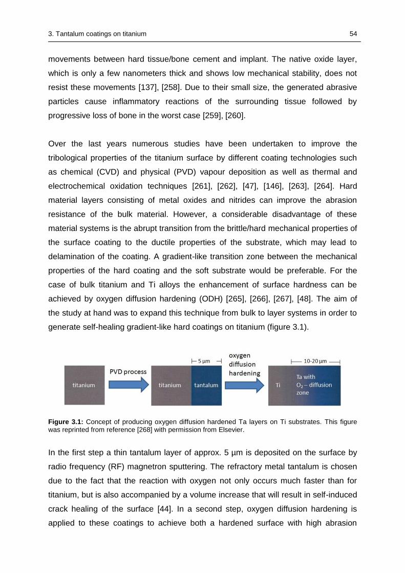
3. Tantalum coatings on titanium 54
movements between hard tissue/bone cement and implant. The native oxide layer,
which is only a few nanometers thick and shows low mechanical stability, does not
resist these movements [137], [258]. Due to their small size, the generated abrasive
particles cause inflammatory reactions of the surrounding tissue followed by
progressive loss of bone in the worst case [259], [260].
Over the last years numerous studies have been undertaken to improve the
tribological properties of the titanium surface by different coating technologies such
as chemical (CVD) and physical (PVD) vapour deposition as well as thermal and
electrochemical oxidation techniques [261], [262], [47], [146], [263], [264]. Hard
material layers consisting of metal oxides and nitrides can improve the abrasion
resistance of the bulk material. However, a considerable disadvantage of these
material systems is the abrupt transition from the brittle/hard mechanical properties of
the surface coating to the ductile properties of the substrate, which may lead to
delamination of the coating. A gradient-like transition zone between the mechanical
properties of the hard coating and the soft substrate would be preferable. For the
case of bulk titanium and Ti alloys the enhancement of surface hardness can be
achieved by oxygen diffusion hardening (ODH) [265], [266], [267], [48]. The aim of
the study at hand was to expand this technique from bulk to layer systems in order to
generate self-healing gradient-like hard coatings on titanium (figure 3.1).
Figure 3.1: Concept of producing oxygen diffusion hardened Ta layers on Ti substrates. This figure was reprinted from reference [268] with permission from Elsevier.
In the first step a thin tantalum layer of approx. 5 µm is deposited on the surface by
radio frequency (RF) magnetron sputtering. The refractory metal tantalum is chosen
due to the fact that the reaction with oxygen not only occurs much faster than for
titanium, but is also accompanied by a volume increase that will result in self-induced
crack healing of the surface [44]. In a second step, oxygen diffusion hardening is
applied to these coatings to achieve both a hardened surface with high abrasion
3. Tantalum coatings on titanium 55
resistance and a smooth transition zone of mechanical properties from the surface to
the bulk material. The coatings then are characterized regarding their chemical
composition, morphology and adhesion using X-ray diffraction analysis, scanning
electron microscopy (SEM), Rockwell testing and Vickers hardness measurement.
3.2 Materials and experimental methods
3.2.1 Sample preparation and coating process
Tantalum films were deposited on commercially pure titanium discs (grade 2,
15.5 mm diameter, 1 mm height) by RF-magnetron sputtering using a Ta target
(120 mm diameter, 10 mm height) with a target-to-substrate distance of 100 mm. Ti
discs were mechanically ground and polished to mirror-like appearance. All
substrates were cleaned in an ultrasonic bath (first with acetone for 10 min, then with
ethanol for 10 min) and finally dried in air. The Ti samples were attached to the
substrate holder of a PVD-system of type PLS 570 (Pfeiffer Vacuum, Asslar,
Germany). The substrate holder was especially designed for this purpose and could
be heated by a pair of internally installed halogen lamps. The temperature was
measured by a thermocouple that was embedded between two titanium samples.
The chamber was evacuated for 15 hours at a temperature of 40 °C followed by a
one hour cool-down to 15 °C, with both heating and cooling achieved by means of
temperature-stabilized water circulation. This procedure resulted in a base pressure
of 1*10-6 mbar. 30 min before deposition the substrate holder was heated up to
350 °C or 450 °C. Prior to deposition the substrates were sputter-cleaned in argon
plasma (300 W, 180 sccm, 1.6*10-2 mbar) for 10 - 15 min.
A wide range of process parameters for sputter deposition could be varied, such as
deposition time (180 - 300 min), working pressure (6.7 – 9.9 * 10-3 mbar), negative
substrate bias voltage (0 - 300 V) and substrate temperatures up to 550 °C.
However, the coatings examined in this study were deposited with a set of fixed
parameters, namely a deposition time of 180 min, a working pressure of
7.0*10-3 mbar (100 sccm Argon) and a substrate bias voltage of 0 V, while the
substrate temperature was either 350 or 450 °C. On the basis of measured thickness
and deposition time the calculated deposition rate was approximately 0.5 nm/s.
3. Tantalum coatings on titanium 56
3.2.2 Oxygen diffusion hardening
Following the deposition process the substrate temperature was kept for 3 h at either
350 or 450 °C. In order to achieve oxygen diffusion hardening directly after finishing
the sputter deposition process, the working gas argon was replaced with oxygen
(100 sccm), resulting in a pressure of 6.7*10-3 mbar. The samples were kept in this
oxygen atmosphere at the elevated temperatures for one or two hours. Then oxygen
was removed from the chamber and the samples were heated for additional one to
two hours without process gas. Finally the substrates were cooled down to room
temperature before venting the chamber.
3.2.3 Coating characterization
Morphology
The surface morphology of the coatings was determined by scanning electron
microscopy (SEM) using a microscope DSM 940 (Zeiss, Oberkochen, Germany). The
film thicknesses were determined by the evaluation of SEM images of either cross
sections of Ti discs or by disruption of Ta coated titanium foils. The deposited mass
was determined by measuring the mass of the samples before and after deposition
using a precision balance of type MC1 (Sartorius, Göttingen, Germany). Then the
obtained values for film thickness and mass were used to calculate the density of the
deposited coatings.
XRD
The crystal structure of the tantalum films was examined by X-ray diffraction (XRD) in
Bragg-Brentano geometry with a Siemens D5005 X-ray diffractometer (Bruker AXS,
Karlsruhe, Germany) using Cu-Kα radiation with a voltage of 40 kV and a tube
current of 40 mA.
Oxygen concentration(#)
Depth profiles of the oxygen concentration in the ODH treated samples were
recorded by sputter ablation of the surface and analysis of the released atoms using
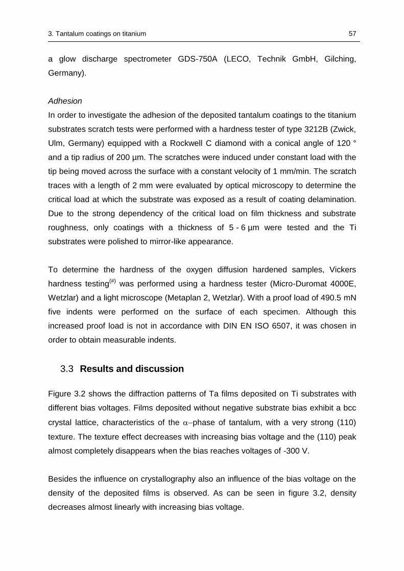
3. Tantalum coatings on titanium 57
a glow discharge spectrometer GDS-750A (LECO, Technik GmbH, Gilching,
Germany).
Adhesion
In order to investigate the adhesion of the deposited tantalum coatings to the titanium
substrates scratch tests were performed with a hardness tester of type 3212B (Zwick,
Ulm, Germany) equipped with a Rockwell C diamond with a conical angle of 120 °
and a tip radius of 200 µm. The scratches were induced under constant load with the
tip being moved across the surface with a constant velocity of 1 mm/min. The scratch
traces with a length of 2 mm were evaluated by optical microscopy to determine the
critical load at which the substrate was exposed as a result of coating delamination.
Due to the strong dependency of the critical load on film thickness and substrate
roughness, only coatings with a thickness of 5 - 6 µm were tested and the Ti
substrates were polished to mirror-like appearance.
To determine the hardness of the oxygen diffusion hardened samples, Vickers
hardness testing(#) was performed using a hardness tester (Micro-Duromat 4000E,
Wetzlar) and a light microscope (Metaplan 2, Wetzlar). With a proof load of 490.5 mN
five indents were performed on the surface of each specimen. Although this
increased proof load is not in accordance with DIN EN ISO 6507, it was chosen in
order to obtain measurable indents.
3.3 Results and discussion
Figure 3.2 shows the diffraction patterns of Ta films deposited on Ti substrates with
different bias voltages. Films deposited without negative substrate bias exhibit a bcc
crystal lattice, characteristics of the phase of tantalum, with a very strong (110)
texture. The texture effect decreases with increasing bias voltage and the (110) peak
almost completely disappears when the bias reaches voltages of -300 V.
Besides the influence on crystallography also an influence of the bias voltage on the
density of the deposited films is observed. As can be seen in figure 3.2, density
decreases almost linearly with increasing bias voltage.
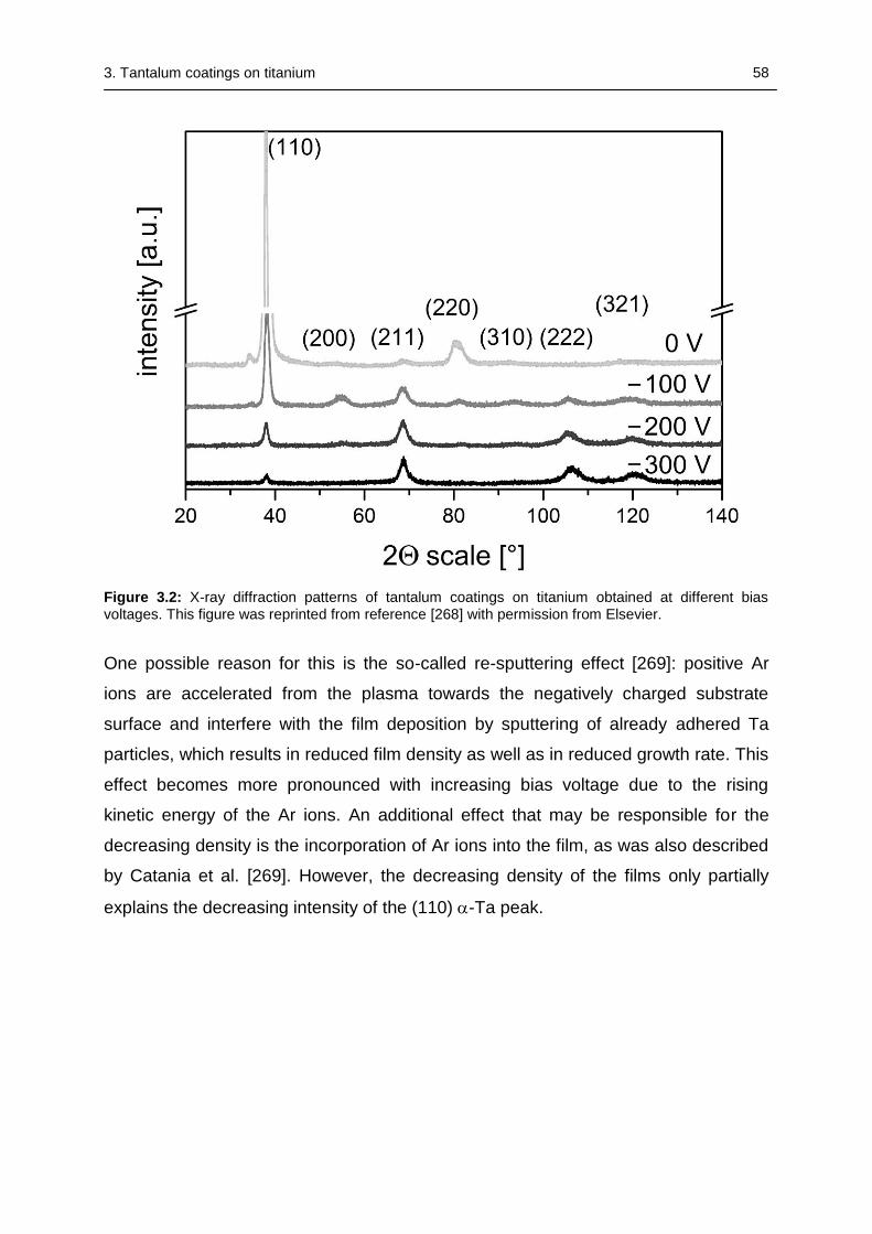
3. Tantalum coatings on titanium 58
Figure 3.2: X-ray diffraction patterns of tantalum coatings on titanium obtained at different bias voltages. This figure was reprinted from reference [268] with permission from Elsevier.
One possible reason for this is the so-called re-sputtering effect [269]: positive Ar
ions are accelerated from the plasma towards the negatively charged substrate
surface and interfere with the film deposition by sputtering of already adhered Ta
particles, which results in reduced film density as well as in reduced growth rate. This
effect becomes more pronounced with increasing bias voltage due to the rising
kinetic energy of the Ar ions. An additional effect that may be responsible for the
decreasing density is the incorporation of Ar ions into the film, as was also described
by Catania et al. [269]. However, the decreasing density of the films only partially
explains the decreasing intensity of the (110) -Ta peak.
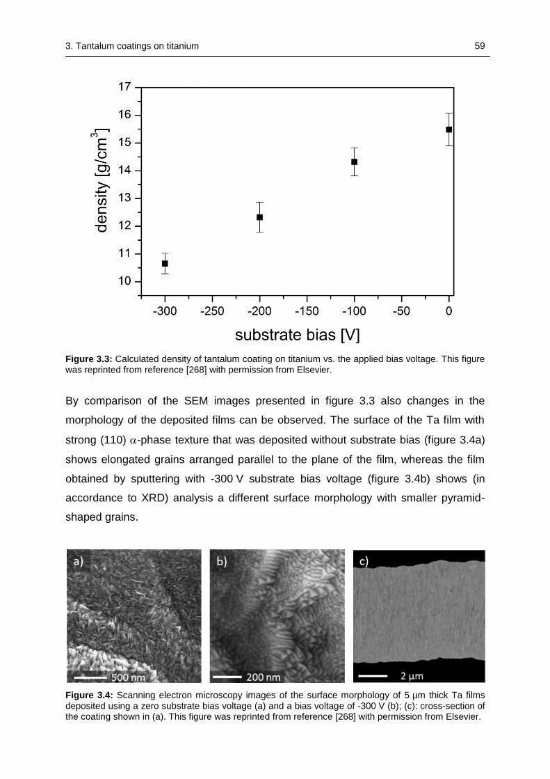
3. Tantalum coatings on titanium 59
Figure 3.3: Calculated density of tantalum coating on titanium vs. the applied bias voltage. This figure was reprinted from reference [268] with permission from Elsevier.
By comparison of the SEM images presented in figure 3.3 also changes in the
morphology of the deposited films can be observed. The surface of the Ta film with
strong (110) -phase texture that was deposited without substrate bias (figure 3.4a)
shows elongated grains arranged parallel to the plane of the film, whereas the film
obtained by sputtering with -300 V substrate bias voltage (figure 3.4b) shows (in
accordance to XRD) analysis a different surface morphology with smaller pyramid-
shaped grains.
Figure 3.4: Scanning electron microscopy images of the surface morphology of 5 µm thick Ta films deposited using a zero substrate bias voltage (a) and a bias voltage of -300 V (b); (c): cross-section of the coating shown in (a). This figure was reprinted from reference [268] with permission from Elsevier.
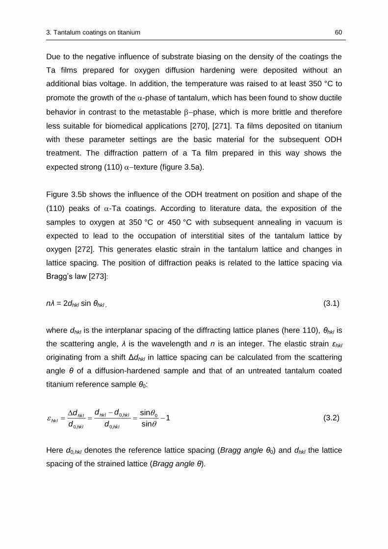
3. Tantalum coatings on titanium 60
Due to the negative influence of substrate biasing on the density of the coatings the
Ta films prepared for oxygen diffusion hardening were deposited without an
additional bias voltage. In addition, the temperature was raised to at least 350 °C to
promote the growth of the -phase of tantalum, which has been found to show ductile
behavior in contrast to the metastable phase, which is more brittle and therefore
less suitable for biomedical applications [270], [271]. Ta films deposited on titanium
with these parameter settings are the basic material for the subsequent ODH
treatment. The diffraction pattern of a Ta film prepared in this way shows the
expected strong (110) texture (figure 3.5a).
Figure 3.5b shows the influence of the ODH treatment on position and shape of the
(110) peaks of -Ta coatings. According to literature data, the exposition of the
samples to oxygen at 350 °C or 450 °C with subsequent annealing in vacuum is
expected to lead to the occupation of interstitial sites of the tantalum lattice by
oxygen [272]. This generates elastic strain in the tantalum lattice and changes in
lattice spacing. The position of diffraction peaks is related to the lattice spacing via
Bragg’s law [273]:
nλ = 2dhkl sin θhkl , (3.1)
where dhkl is the interplanar spacing of the diffracting lattice planes (here 110), θhkl is
the scattering angle, λ is the wavelength and n is an integer. The elastic strain εhkl
originating from a shift Δdhkl in lattice spacing can be calculated from the scattering
angle θ of a diffusion-hardened sample and that of an untreated tantalum coated
titanium reference sample θ0:
1sin
sin 0
,0
,0
,0
hkl
hklhkl
hkl
hklhkl
d
dd
d
d (3.2)
Here d0,hkl denotes the reference lattice spacing (Bragg angle θ0) and dhkl the lattice
spacing of the strained lattice (Bragg angle θ).
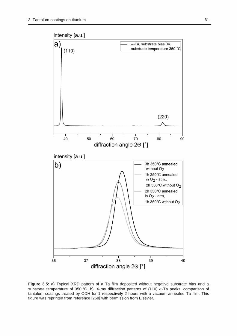
3. Tantalum coatings on titanium 61
Figure 3.5: a) Typical XRD pattern of a Ta film deposited without negative substrate bias and a
substrate temperature of 350 °C. b). X-ray diffraction patterns of (110) -Ta peaks; comparison of tantalum coatings treated by ODH for 1 respectively 2 hours with a vacuum annealed Ta film. This figure was reprinted from reference [268] with permission from Elsevier.
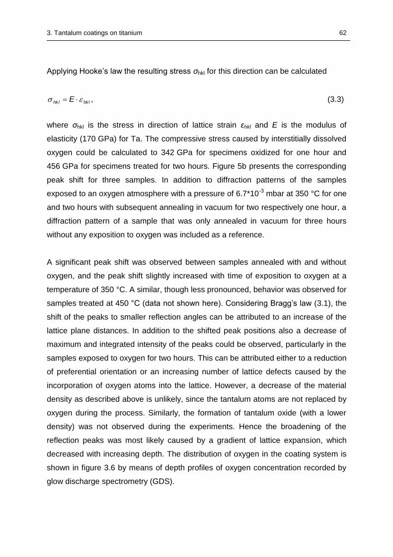
3. Tantalum coatings on titanium 62
Applying Hooke’s law the resulting stress σhkl for this direction can be calculated
hklhkl E , (3.3)
where σhkl is the stress in direction of lattice strain εhkl and E is the modulus of
elasticity (170 GPa) for Ta. The compressive stress caused by interstitially dissolved
oxygen could be calculated to 342 GPa for specimens oxidized for one hour and
456 GPa for specimens treated for two hours. Figure 5b presents the corresponding
peak shift for three samples. In addition to diffraction patterns of the samples
exposed to an oxygen atmosphere with a pressure of 6.7*10-3 mbar at 350 °C for one
and two hours with subsequent annealing in vacuum for two respectively one hour, a
diffraction pattern of a sample that was only annealed in vacuum for three hours
without any exposition to oxygen was included as a reference.
A significant peak shift was observed between samples annealed with and without
oxygen, and the peak shift slightly increased with time of exposition to oxygen at a
temperature of 350 °C. A similar, though less pronounced, behavior was observed for
samples treated at 450 °C (data not shown here). Considering Bragg’s law (3.1), the
shift of the peaks to smaller reflection angles can be attributed to an increase of the
lattice plane distances. In addition to the shifted peak positions also a decrease of
maximum and integrated intensity of the peaks could be observed, particularly in the
samples exposed to oxygen for two hours. This can be attributed either to a reduction
of preferential orientation or an increasing number of lattice defects caused by the
incorporation of oxygen atoms into the lattice. However, a decrease of the material
density as described above is unlikely, since the tantalum atoms are not replaced by
oxygen during the process. Similarly, the formation of tantalum oxide (with a lower
density) was not observed during the experiments. Hence the broadening of the
reflection peaks was most likely caused by a gradient of lattice expansion, which
decreased with increasing depth. The distribution of oxygen in the coating system is
shown in figure 3.6 by means of depth profiles of oxygen concentration recorded by
glow discharge spectrometry (GDS).
3. Tantalum coatings on titanium 63
Figure 3.6: GDS depth profiles of oxygen concentration in Ta coatings treated with the following parameters: a: 350 °C for 1 h, b: 350 °C for 2 h, c: 450 °C for 1 h, 450 °C for 2 h. The profiles have been shifted on the abscissa with respect to the layer thickness. This figure was reprinted from reference [268] with permission from Elsevier.
(#)
Significant differences between samples treated with different parameters could be
mainly observed in the depicted depth range, particularly in the region across the
interface between substrate and layer, where the oxygen concentration in the lattice
markedly increased when the process temperature was elevated from 350 °C to
450 °C. The depth profiles of the samples treated at 350 °C showed only a negligible
influence of the duration of the ODH process, which supports the above-mentioned
assumption that the slight peak shift and the reduction of peak intensity in the
diffraction patterns (figure 3.5) may have only occurred due to thermal effects rather
than to differences in oxygen incorporation. However, the curves of the samples
treated at 450 °C showed a pronounced local maximum of the oxygen concentration,
which was shifted deeper into the sample, when the treatment was maintained for
2 h. This accumulation of oxygen at the interface could only be observed at the
higher treatment temperature, which suggests significantly differing diffusion rates of
the oxygen molecules in the coating and in the substrate. Obviously this difference
was much more pronounced at 450 °C, which partially inhibited the propagation of
3. Tantalum coatings on titanium 64
oxygen across the Ta/Ti interface and led to the observed accumulation. However,
increasing the treatment duration at 450 °C appears to support the incorporation of
oxygen into the deeper regions beyond the interface.
The main objective of the ODH treatment of tantalum coatings was to develop
potential protective coatings for titanium substrates in biomedical applications where
mechanical stress is involved. Therefore, besides the crystallographic properties of
the deposited films, also their hardness and their adhesion to the substrate were of
crucial importance. The determination of critical loads of the coatings is strongly
influenced by the underlying substrate, i.e. by its mechanical and topographical
properties like surface hardness and roughness. The results obtained from
measurements on different coating–substrate systems must be evaluated with
caution; actually it seems appropriate to restrict the evaluation of film adhesion to
relative results from measurements within one coating-substrate system. In this work
the material system chosen for the investigation of its potential adhesion
improvement by oxygen diffusion hardening consisted of Ti substrate, polished to
mirror-like surface roughness and coated with a Ta layer of approximately 5 µm
thickness.
The evaluation of the adhesion between substrate and coating is commonly done by
the measurement of the critical force when coating delamination occurs and the
substrate becomes exposed. In the scratch tests performed the ODH treated
samples partially exhibited significant improvement of adhesion. The determined
values for the critical force LC were typically in the range of 9–12 N for the untreated
samples, but reached values up to 25 N for some ODH treated samples. Figure 7
shows the tracks induced by scratch tests on samples that were coated with Ta in the
same way, but underwent different treatment afterwards. Figures 7 a-c show the
grooves obtained from scratch tests performed with loads slightly below LC. Small
cracks occurred in the track, which ran perpendicular to the direction of the tip’s
movement. This cracking is due to sticking (initial) friction between diamond and
coating at the sides of the Rockwell-indenter [274]. Figures 7 e-f show that depth and
width of the cracks increase with increasing load until reaching LC at which the
titanium substrate was exposed partially.
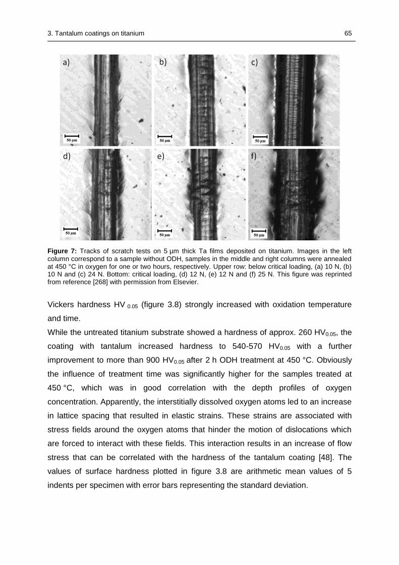
3. Tantalum coatings on titanium 65
Figure 7: Tracks of scratch tests on 5 µm thick Ta films deposited on titanium. Images in the left column correspond to a sample without ODH, samples in the middle and right columns were annealed at 450 °C in oxygen for one or two hours, respectively. Upper row: below critical loading, (a) 10 N, (b) 10 N and (c) 24 N. Bottom: critical loading, (d) 12 N, (e) 12 N and (f) 25 N. This figure was reprinted from reference [268] with permission from Elsevier.
Vickers hardness HV 0.05 (figure 3.8) strongly increased with oxidation temperature
and time.
While the untreated titanium substrate showed a hardness of approx. 260 HV0.05, the
coating with tantalum increased hardness to 540-570 HV0.05 with a further
improvement to more than 900 HV0.05 after 2 h ODH treatment at 450 °C. Obviously
the influence of treatment time was significantly higher for the samples treated at
450 °C, which was in good correlation with the depth profiles of oxygen
concentration. Apparently, the interstitially dissolved oxygen atoms led to an increase
in lattice spacing that resulted in elastic strains. These strains are associated with
stress fields around the oxygen atoms that hinder the motion of dislocations which
are forced to interact with these fields. This interaction results in an increase of flow
stress that can be correlated with the hardness of the tantalum coating [48]. The
values of surface hardness plotted in figure 3.8 are arithmetic mean values of 5
indents per specimen with error bars representing the standard deviation.
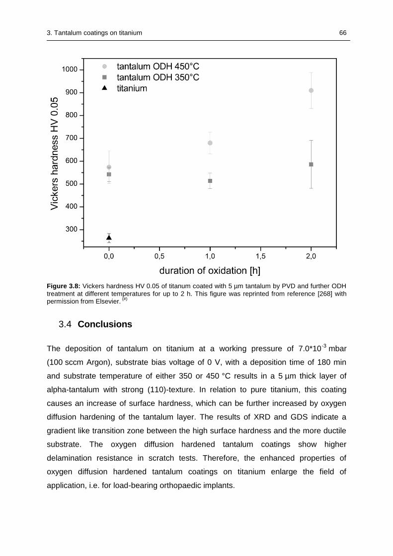
3. Tantalum coatings on titanium 66
Figure 3.8: Vickers hardness HV 0.05 of titanum coated with 5 µm tantalum by PVD and further ODH treatment at different temperatures for up to 2 h. This figure was reprinted from reference [268] with permission from Elsevier.
(#)
3.4 Conclusions
The deposition of tantalum on titanium at a working pressure of 7.0*10-3 mbar
(100 sccm Argon), substrate bias voltage of 0 V, with a deposition time of 180 min
and substrate temperature of either 350 or 450 °C results in a 5 µm thick layer of
alpha-tantalum with strong (110)-texture. In relation to pure titanium, this coating
causes an increase of surface hardness, which can be further increased by oxygen
diffusion hardening of the tantalum layer. The results of XRD and GDS indicate a
gradient like transition zone between the high surface hardness and the more ductile
substrate. The oxygen diffusion hardened tantalum coatings show higher
delamination resistance in scratch tests. Therefore, the enhanced properties of
oxygen diffusion hardened tantalum coatings on titanium enlarge the field of
application, i.e. for load-bearing orthopaedic implants.
4. TiAg coatings 67
4 PHYSICAL AND CHEMICAL CHARACTERIZATION OF AG-
DOPED TI COATINGS PRODUCED BY MAGNETRON
SPUTTERING OF MODULAR TARGETS
This Chapter was already published as original research article in
Schmitz T, Warmuth F, Werner E, Hertl C, Groll J, Gbureck U, C. Moseke. Physical
and chemical characterization of Ag-doped Ti coatings produced by magnetron
sputtering of modular targets. Materials Science & Engineering C-Materials for
Biological Applications 2014;44:126-31).
This work was performed in the framework of a joint DFG project between the
Department for Material Science and Mechanics (Prof. E. Werner, Technical
University Munich) and Department for Functional Materials in Medicine and
Dentistry (Prof. U. Gbureck, University of Würzburg). Contact angle and elution
measurements as well as the examination of the total amount and distribution of
silver were performed by Franziska Warmuth as part of a diploma thesis [275]. These
parts are marked with a hash (#).
4. TiAg coatings 68
Abstract
Silver-doped Ti films were produced using a single magnetron sputtering source
equipped with a titanium target containing implemented silver modules under
variation of bias voltage and substrate temperature. The Ti(Ag) films were
characterized regarding their morphology, contact angle, phase composition, silver
content and distribution as well as the elution of Ag+ ions into cell media.
SEM and AFM pictures showed that substrate heating during film deposition
supported the formation of even and dense surface layers with small roughness
values, an effect that could even be enforced, when a substrate bias voltage was
applied instead. The deposition of both Ti and Ag was confirmed by X-ray diffraction.
ICP-MS and EDX showed a clear correlation between the applied sputtering
parameters and the silver content of the coatings. Surface-sensitive XPS
measurements revealed that higher substrate temperatures led to an accumulation of
Ag in the near-surface region, while the application of a bias voltage had the opposite
effect. Additional elution measurements using ICP-MS showed that the release
kinetics depended on the amount of silver located at the film surface and hence could
be tailored by variation of the sputter parameters.
4.1 Introduction
Changes in life expectancy as well as in life style of the population particularly in the
industrial nations lead to significantly increasing demands for total joint arthroplasty, a
trend which is likely to continue for the next decades [5], [276], [277]. The metallic
materials (mostly titanium and its alloys) designated for usage in load bearing
applications like hip and knee arthroplasty have to meet growing demands not only to
the mechanical properties, but also to their potential to avoid bacterial infections in
the application site. The average risk of infection after the first implantation of artificial
hip or knee joints is about 1-4%, a value which rises up to about 17% after revision
surgery [278]. Bacterial infections, which may in the worst case lead to the loss of the
implant, can be caused either by microorganisms invading the wound during surgery
or by bacteria already existing in the patient’s blood [279]. Strategies against these
complications comprise preventive measures like improving the hygienic standards in
operation rooms. However, after an infection has occurred treatment is difficult,
because the bacteria form a biofilm on the infected surface, which inhibits the
4. TiAg coatings 69
penetration of antimicrobial agents like antibiotics. In addition, the number of bacteria
stems forming resistances against antibiotics is increasing [280]. An alternative
method for infection prevention lies in the modification of the implant surface itself by
deposition of functional coatings. The perfect surface would combine mechanical
resistivity with enhanced biological features like bioactivity and bactericidity, i.e. it
should promote the adhesion of osteoinductive cells on one hand and repel or kill
detrimental microorganisms on the other. Metal ions like silver, copper or zinc have
been shown to provide good antimicrobial potential as well as good biocompatibility
[281]. Particularly silver has been known for its bactericidal behavior for ancient time
and is already being used in several medical devices, e.g. in wound dressings and
surgical instruments [282], [283]. The potential use of silver as a dopant for functional
coatings has been reported in several studies [284], [285], [145], [143], [286]. A
previous study of our work group combined two physical vapor deposition (PVD)
techniques to coat Ti substrates with Ag containing Ti films [47]. In brief, a titanium
target was evaporated by arc technique, while a silver target on the opposite side
was magnetron sputtered, leading to a deposition of Ti(Ag) films on substrates that
were moved on a circle alongside both evaporators. The same method was applied
to the deposition of Ag-containing TiN films, which showed – in addition to their
antibacterial and biocompatible properties – enhanced mechanical resistivity [146].
However, the comparison to results from similar achievements in other groups (e.g.
Iordanova et al.) revealed that Ag-doped coatings maybe deposited by various
methods, but the phases in which Ag will appear significantly depend on the applied
process parameters [287]. While arc evaporation is a process involving high
substrate temperatures, better control of the process might be accessible by the
simultaneous usage of more than one magnetron sputter source or by single
magnetron sputtering of a combined target material. However, the production of an
alloyed target is a difficult and expensive task and furthermore requires the
fabrication of new targets for every variation of the coating composition.
The aim of this study was to design an inexpensive and versatile alternative to
alloyed targets, namely modular titanium-silver targets, which allow to create Ti(Ag)
coatings with varying silver content by easy modification of the silver assembly to a
permanent Ti basis. The work was focused on the influence of sputtering parameters
(substrate bias, substrate temperature) on silver content and distribution in the
as-deposited coatings. Furthermore, elution experiments in cell culture medium were
4. TiAg coatings 70
performed to evaluate the release kinetics of silver ions, an essential characteristic
for the antimicrobial potential of these surface modifications.
4.2 Materials and Methods
4.2.1 Substrate preparation
In general, disc-shaped substrates with a diameter of 15.5 mm and 1 mm thickness
made from Ti plate (grade 2, Zapp Materials Engineering, Ratingen, Germany) were
used for coating. In addition, rectangular glass slides (76 x 26 x 1 mm) were
simultaneously coated to enable determination of the silver content in the obtained
coatings without disturbing effects of dissolved substrate material during the etching
process. To ensure the comparability of measuring results obtained from the analysis
of coatings on both polished Ti substrates and glass slides, extensive test series had
been performed that showed no significant differences between both substrates.
Hereby, the utilization of glass slides as a model substrate with a high uniformity
could be justified. Prior to coating deposition, all substrates were thoroughly cleaned
in an ultrasonic bath (BANDELIN electronic, Berlin, Germany) with acetone, ethanol,
and ultrapure water, with every cleaning step being carried out for 10 min.
Subsequently all the substrates were dried by means of nitrogen gas.
4.2.2 Target preparation
Conventional disc-shaped Ti targets were modified with circular concentrated holes
(Ø= 5 mm) which were filled with silver nuggets using a mechanical press and
subsequent spot-welding. The Ag nuggets were positioned on the circle with the
highest sputter erosion. It was then possible to change the silver fraction in the
coating by altering the number of holes filled with Ag. In this study we concentrated
on samples that were prepared with a target equipped with four silver modules.
4.2.3 Physical Vapor Deposition
Deposition of silver-doped Ti coatings was carried out in a vacuum chamber (Pfeiffer
Vacuum, Asslar, Germany) equipped with a magnetron sputter coater and a custom-
made substrate heating. Composition and flow rate of the process gas were adjusted
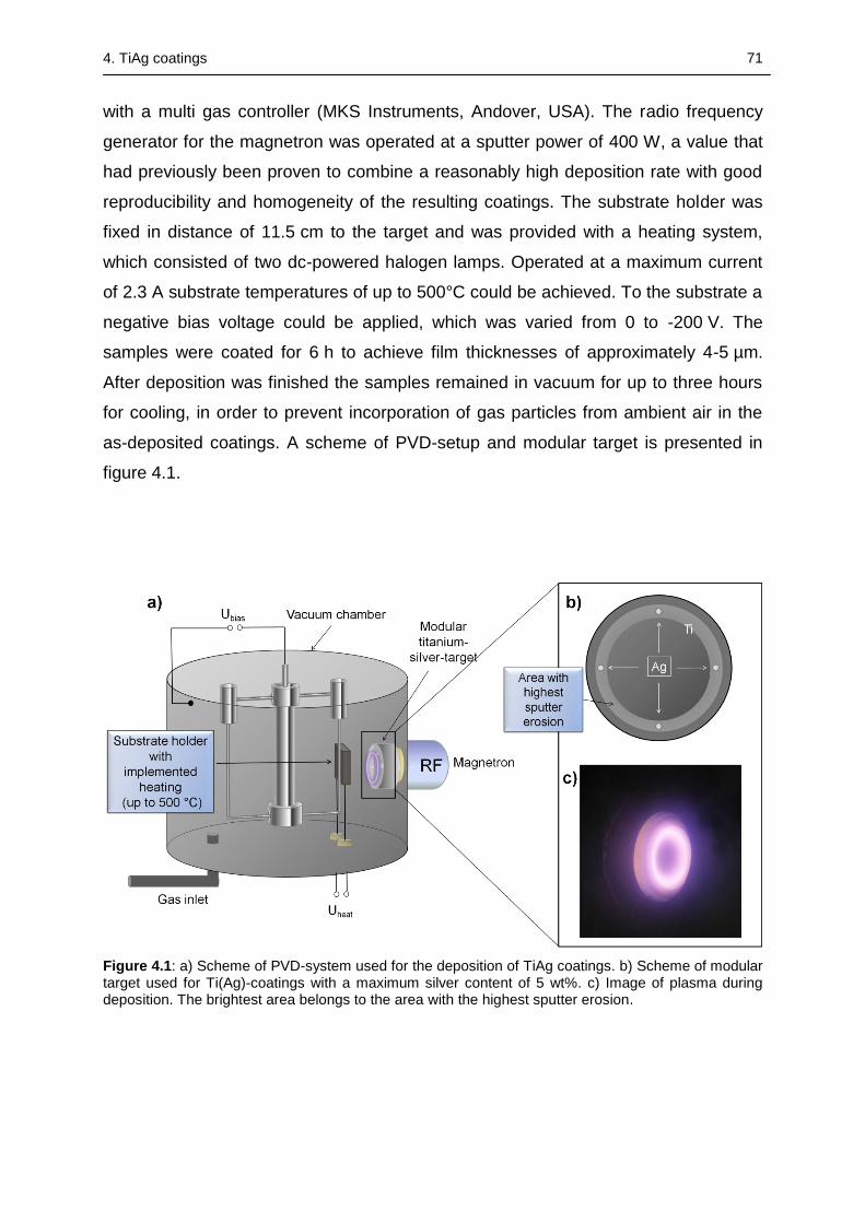
4. TiAg coatings 71
with a multi gas controller (MKS Instruments, Andover, USA). The radio frequency
generator for the magnetron was operated at a sputter power of 400 W, a value that
had previously been proven to combine a reasonably high deposition rate with good
reproducibility and homogeneity of the resulting coatings. The substrate holder was
fixed in distance of 11.5 cm to the target and was provided with a heating system,
which consisted of two dc-powered halogen lamps. Operated at a maximum current
of 2.3 A substrate temperatures of up to 500°C could be achieved. To the substrate a
negative bias voltage could be applied, which was varied from 0 to -200 V. The
samples were coated for 6 h to achieve film thicknesses of approximately 4-5 µm.
After deposition was finished the samples remained in vacuum for up to three hours
for cooling, in order to prevent incorporation of gas particles from ambient air in the
as-deposited coatings. A scheme of PVD-setup and modular target is presented in
figure 4.1.
Figure 4.1: a) Scheme of PVD-system used for the deposition of TiAg coatings. b) Scheme of modular target used for Ti(Ag)-coatings with a maximum silver content of 5 wt%. c) Image of plasma during deposition. The brightest area belongs to the area with the highest sputter erosion.
4. TiAg coatings 72
4.2.4 Coating characterization
Morphology and surface roughness
The surface morphology of the coatings was determined by scanning electron
microscopy (SEM) using a high resolution SEM (Zeiss CB 340, Oberkochen,
Germany), which was also equipped with a focused ion beam (FIB). Additionally an
atomic force microscope Nanosurf FlexAFM (Nanosurf GmbH, Langen, Germany)
was used to scan the surface morphology of Ti(Ag) films deposited on glass slides
and to quantitatively measure and analyze the surface roughness on the nanometer
scale using the standard instrument software Nanosurf Easyscan 2. To quantify the
area roughness parameters Sa and Sq each sample was scanned three times on
different positions with scan fields of approximately 5 µm x 5 µm. Each sample was
analyzed in air under tapping mode using a silicon cantilever Tap190-Al G
(Innovative Solutions Bulgaria Ltd, Sofia, Bulgaria) with a tip radius smaller
than10 nm.
Silver content and distribution(#)
To determine the entire silver content of the coatings, films deposited on glass slides
were carefully scraped of the glass substrate with a scalpel and then dissolved in a
diluted mixture of hydrofluoric and nitric acid. The obtained solutions were diluted
with ultrapure water (1:100, 1:1000 and 1:10000) and analyzed by means of
inductively coupled plasma mass spectrometry (ICP-MS, Varian). In addition, energy
dispersive X-ray analysis was performed using an EDX detector Ultra 55+ (Zeiss,
Oberkochen, Germany). The fraction of silver on the surface of the thin films was
determined by X-ray photoelectron spectroscopy (SES 200, VG Scienta, Uppsala,
Sweden) using Al-Kradiation.
XRD
The crystal structure of the coatings was analyzed by X-ray diffraction (XRD) in
grazing incidence geometry with a Siemens D5005 X-ray diffractometer (Bruker AXS,
Karlsruhe, Germany) using Cu-Kradiation with a voltage of 40 kV and a tube current
of 40 mA. The diffraction patterns recorded in a 2Θ range from 30-85° were
evaluated with the software DiffracPlus EVA (Bruker AXS, Karlsruhe, Germany) and
compared with reference patterns from the JCPDS database [288].
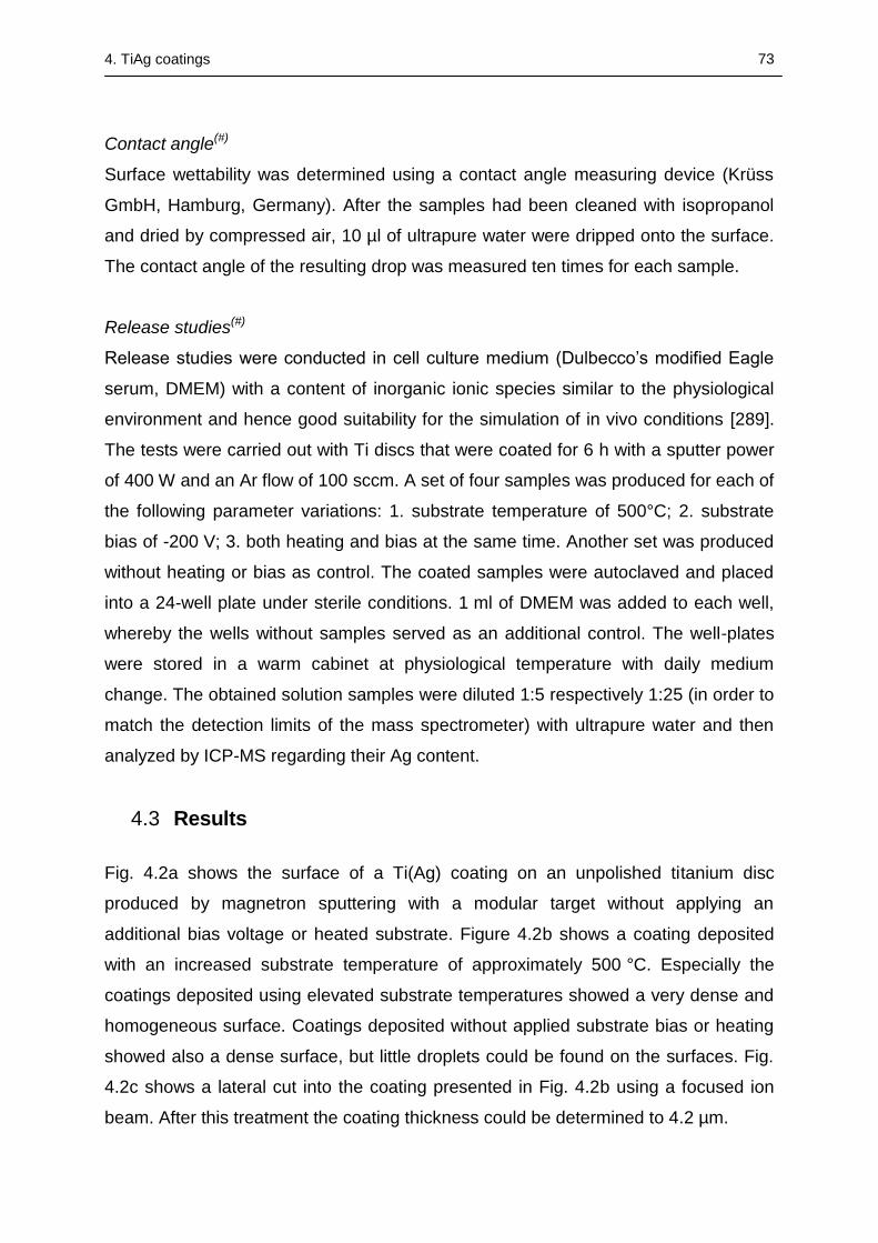
4. TiAg coatings 73
Contact angle(#)
Surface wettability was determined using a contact angle measuring device (Krüss
GmbH, Hamburg, Germany). After the samples had been cleaned with isopropanol
and dried by compressed air, 10 µl of ultrapure water were dripped onto the surface.
The contact angle of the resulting drop was measured ten times for each sample.
Release studies(#)
Release studies were conducted in cell culture medium (Dulbecco’s modified Eagle
serum, DMEM) with a content of inorganic ionic species similar to the physiological
environment and hence good suitability for the simulation of in vivo conditions [289].
The tests were carried out with Ti discs that were coated for 6 h with a sputter power
of 400 W and an Ar flow of 100 sccm. A set of four samples was produced for each of
the following parameter variations: 1. substrate temperature of 500°C; 2. substrate
bias of -200 V; 3. both heating and bias at the same time. Another set was produced
without heating or bias as control. The coated samples were autoclaved and placed
into a 24-well plate under sterile conditions. 1 ml of DMEM was added to each well,
whereby the wells without samples served as an additional control. The well-plates
were stored in a warm cabinet at physiological temperature with daily medium
change. The obtained solution samples were diluted 1:5 respectively 1:25 (in order to
match the detection limits of the mass spectrometer) with ultrapure water and then
analyzed by ICP-MS regarding their Ag content.
4.3 Results
Fig. 4.2a shows the surface of a Ti(Ag) coating on an unpolished titanium disc
produced by magnetron sputtering with a modular target without applying an
additional bias voltage or heated substrate. Figure 4.2b shows a coating deposited
with an increased substrate temperature of approximately 500 °C. Especially the
coatings deposited using elevated substrate temperatures showed a very dense and
homogeneous surface. Coatings deposited without applied substrate bias or heating
showed also a dense surface, but little droplets could be found on the surfaces. Fig.
4.2c shows a lateral cut into the coating presented in Fig. 4.2b using a focused ion
beam. After this treatment the coating thickness could be determined to 4.2 µm.
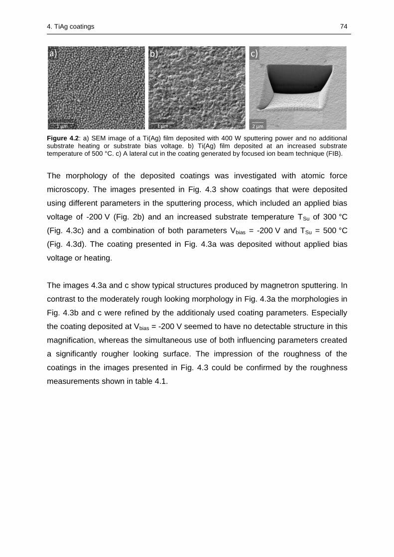
4. TiAg coatings 74
Figure 4.2: a) SEM image of a Ti(Ag) film deposited with 400 W sputtering power and no additional substrate heating or substrate bias voltage. b) Ti(Ag) film deposited at an increased substrate temperature of 500 °C. c) A lateral cut in the coating generated by focused ion beam technique (FIB).
The morphology of the deposited coatings was investigated with atomic force
microscopy. The images presented in Fig. 4.3 show coatings that were deposited
using different parameters in the sputtering process, which included an applied bias
voltage of -200 V (Fig. 2b) and an increased substrate temperature TSu of 300 °C
(Fig. 4.3c) and a combination of both parameters Vbias = -200 V and TSu = 500 °C
(Fig. 4.3d). The coating presented in Fig. 4.3a was deposited without applied bias
voltage or heating.
The images 4.3a and c show typical structures produced by magnetron sputtering. In
contrast to the moderately rough looking morphology in Fig. 4.3a the morphologies in
Fig. 4.3b and c were refined by the additionaly used coating parameters. Especially
the coating deposited at Vbias = -200 V seemed to have no detectable structure in this
magnification, whereas the simultaneous use of both influencing parameters created
a significantly rougher looking surface. The impression of the roughness of the
coatings in the images presented in Fig. 4.3 could be confirmed by the roughness
measurements shown in table 4.1.
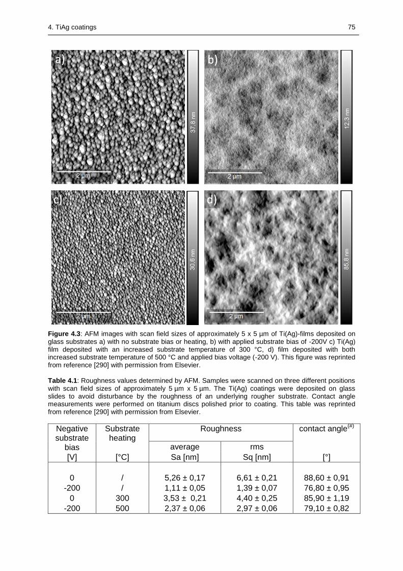
4. TiAg coatings 75
Figure 4.3: AFM images with scan field sizes of approximately 5 x 5 µm of Ti(Ag)-films deposited on glass substrates a) with no substrate bias or heating, b) with applied substrate bias of -200V c) Ti(Ag) film deposited with an increased substrate temperature of 300 °C, d) film deposited with both increased substrate temperature of 500 °C and applied bias voltage (-200 V). This figure was reprinted from reference [290] with permission from Elsevier. Table 4.1: Roughness values determined by AFM. Samples were scanned on three different positions with scan field sizes of approximately 5 µm x 5 µm. The Ti(Ag) coatings were deposited on glass slides to avoid disturbance by the roughness of an underlying rougher substrate. Contact angle measurements were performed on titanium discs polished prior to coating. This table was reprinted from reference [290] with permission from Elsevier.
Negative substrate
bias
Substrate heating
Roughness contact angle(#)
average rms
[V] [°C] Sa [nm] Sq [nm] [°]
0 / 5,26 ± 0,17 6,61 ± 0,21 88,60 ± 0,91
-200 / 1,11 ± 0,05 1,39 ± 0,07 76,80 ± 0,95
0 300 3,53 ± 0,21 4,40 ± 0,25 85,90 ± 1,19
-200 500 2,37 ± 0,06 2,97 ± 0,06 79,10 ± 0,82
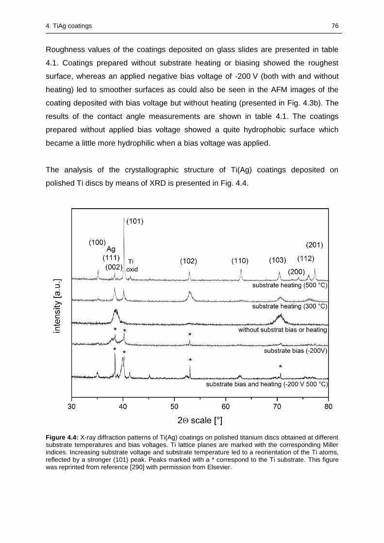
4. TiAg coatings 76
Roughness values of the coatings deposited on glass slides are presented in table
4.1. Coatings prepared without substrate heating or biasing showed the roughest
surface, whereas an applied negative bias voltage of -200 V (both with and without
heating) led to smoother surfaces as could also be seen in the AFM images of the
coating deposited with bias voltage but without heating (presented in Fig. 4.3b). The
results of the contact angle measurements are shown in table 4.1. The coatings
prepared without applied bias voltage showed a quite hydrophobic surface which
became a little more hydrophilic when a bias voltage was applied.
The analysis of the crystallographic structure of Ti(Ag) coatings deposited on
polished Ti discs by means of XRD is presented in Fig. 4.4.
Figure 4.4: X-ray diffraction patterns of Ti(Ag) coatings on polished titanium discs obtained at different substrate temperatures and bias voltages. Ti lattice planes are marked with the corresponding Miller indices. Increasing substrate voltage and substrate temperature led to a reorientation of the Ti atoms, reflected by a stronger (101) peak. Peaks marked with a * correspond to the Ti substrate. This figure was reprinted from reference [290] with permission from Elsevier.
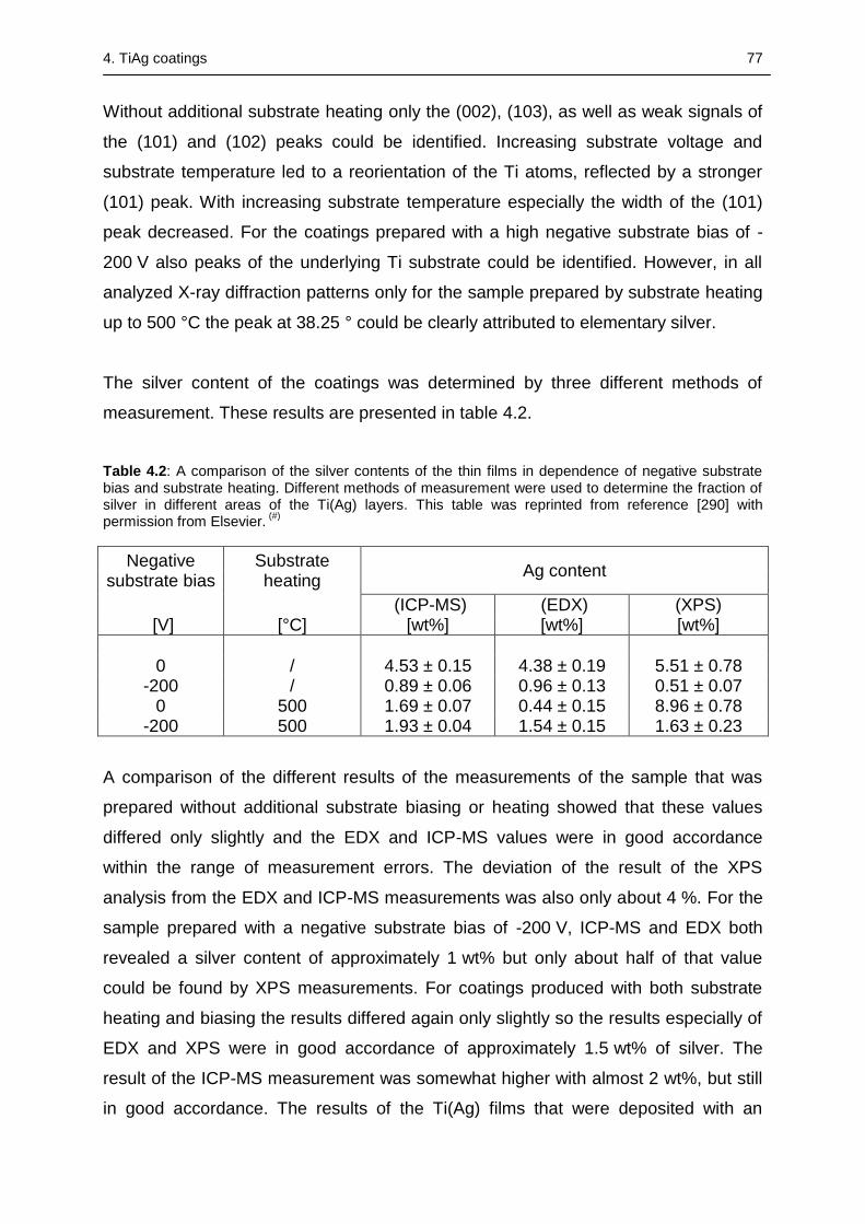
4. TiAg coatings 77
Without additional substrate heating only the (002), (103), as well as weak signals of
the (101) and (102) peaks could be identified. Increasing substrate voltage and
substrate temperature led to a reorientation of the Ti atoms, reflected by a stronger
(101) peak. With increasing substrate temperature especially the width of the (101)
peak decreased. For the coatings prepared with a high negative substrate bias of -
200 V also peaks of the underlying Ti substrate could be identified. However, in all
analyzed X-ray diffraction patterns only for the sample prepared by substrate heating
up to 500 °C the peak at 38.25 ° could be clearly attributed to elementary silver.
The silver content of the coatings was determined by three different methods of
measurement. These results are presented in table 4.2.
Table 4.2: A comparison of the silver contents of the thin films in dependence of negative substrate bias and substrate heating. Different methods of measurement were used to determine the fraction of silver in different areas of the Ti(Ag) layers. This table was reprinted from reference [290] with permission from Elsevier.
(#)
Negative substrate bias
Substrate heating
Ag content
(ICP-MS) (EDX) (XPS) [V] [°C] [wt%] [wt%] [wt%]
0 / 4.53 ± 0.15 4.38 ± 0.19 5.51 ± 0.78
-200 / 0.89 ± 0.06 0.96 ± 0.13 0.51 ± 0.07 0 500 1.69 ± 0.07 0.44 ± 0.15 8.96 ± 0.78
-200 500 1.93 ± 0.04 1.54 ± 0.15 1.63 ± 0.23
A comparison of the different results of the measurements of the sample that was
prepared without additional substrate biasing or heating showed that these values
differed only slightly and the EDX and ICP-MS values were in good accordance
within the range of measurement errors. The deviation of the result of the XPS
analysis from the EDX and ICP-MS measurements was also only about 4 %. For the
sample prepared with a negative substrate bias of -200 V, ICP-MS and EDX both
revealed a silver content of approximately 1 wt% but only about half of that value
could be found by XPS measurements. For coatings produced with both substrate
heating and biasing the results differed again only slightly so the results especially of
EDX and XPS were in good accordance of approximately 1.5 wt% of silver. The
result of the ICP-MS measurement was somewhat higher with almost 2 wt%, but still
in good accordance. The results of the Ti(Ag) films that were deposited with an
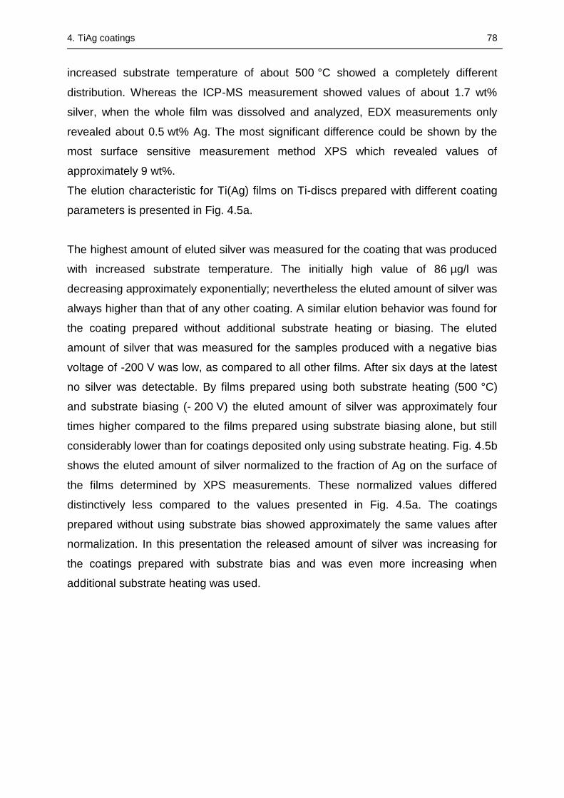
4. TiAg coatings 78
increased substrate temperature of about 500 °C showed a completely different
distribution. Whereas the ICP-MS measurement showed values of about 1.7 wt%
silver, when the whole film was dissolved and analyzed, EDX measurements only
revealed about 0.5 wt% Ag. The most significant difference could be shown by the
most surface sensitive measurement method XPS which revealed values of
approximately 9 wt%.
The elution characteristic for Ti(Ag) films on Ti-discs prepared with different coating
parameters is presented in Fig. 4.5a.
The highest amount of eluted silver was measured for the coating that was produced
with increased substrate temperature. The initially high value of 86 µg/l was
decreasing approximately exponentially; nevertheless the eluted amount of silver was
always higher than that of any other coating. A similar elution behavior was found for
the coating prepared without additional substrate heating or biasing. The eluted
amount of silver that was measured for the samples produced with a negative bias
voltage of -200 V was low, as compared to all other films. After six days at the latest
no silver was detectable. By films prepared using both substrate heating (500 °C)
and substrate biasing (- 200 V) the eluted amount of silver was approximately four
times higher compared to the films prepared using substrate biasing alone, but still
considerably lower than for coatings deposited only using substrate heating. Fig. 4.5b
shows the eluted amount of silver normalized to the fraction of Ag on the surface of
the films determined by XPS measurements. These normalized values differed
distinctively less compared to the values presented in Fig. 4.5a. The coatings
prepared without using substrate bias showed approximately the same values after
normalization. In this presentation the released amount of silver was increasing for
the coatings prepared with substrate bias and was even more increasing when
additional substrate heating was used.
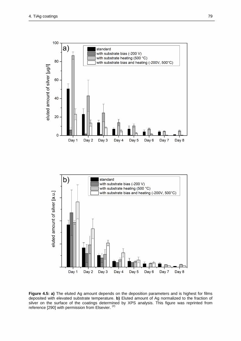
4. TiAg coatings 79
Figure 4.5: a) The eluted Ag amount depends on the deposition parameters and is highest for films deposited with elevated substrate temperature. b) Eluted amount of Ag normalized to the fraction of silver on the surface of the coatings determined by XPS analysis. This figure was reprinted from reference [290] with permission from Elsevier.
(#)
4. TiAg coatings 80
4.4 Discussion
In this study we investigated the production of silver doped titanium coatings using a
combined silver and titanium target where a set of silver modules were pressed into a
titanium target. In addition to the characterization of morphology, surface roughness,
contact angle and crystallographic properties of the coatings we focused on the
distribution and the fraction of incorporated silver in dependency of the applied
sputtering parameters. For the coatings deposited with an increased substrate
temperature or applied bias voltage we could find a refinement of the surface
structure which could also be confirmed by the roughness measurements carried out
along with the AFM investigations. These measurements showed smoother surfaces
for the coatings deposited with additional parameters, particularly with an applied
bias voltage of -200 V, which was in good accordance with findings published by
other groups [291]. A similar but less pronounced effect could be shown for the
coatings deposited at elevated substrate temperature.
A completely different effect could be detected for the coatings produced with a
negative bias voltage and an increased substrate temperature of 500 °C. In this case
the coating roughness even increased, as compared to the coating on a grounded
substrate without elevated substrate temperature. The diffractogram measured for
the coating produced with zero bias voltage and no substrate heating showed a very
broad peak with (002) orientation. This broad peak is typical for coatings with small
grain sizes and is usually being observed in structures obtained by PVD techniques.
Increasing the substrate temperature in the sputtering process led to a reorientation
of the grains from (002) to (010) orientation, an effect which occurred even more
pronounced with increasing substrate temperature. Along with the reorientation the
measured signals became stronger and sharper which could be attributed to growing
grain sizes [292]. A silver peak, Ag (111) at 38.25 °, could be identified in the
diffractogram of the substrate heated sample. This could be explained by two
reasons. For once the reorientation of the grains due to the increasing substrate
temperature led to a decreasing signal of the (002) Ti peak that usually appears at a
diffraction angle of 38.4 °, hence the (111) Ag peak was most probably
indistinguishable from the broadened (002) Ti peaks in case of an unheated
substrate. Another possible explanation is the significantly increased silver fraction on
surface of the heated film that could be detected by XPS measurements (see table
4. TiAg coatings 81
4.2). The film growth was significantly reduced by a high bias voltage of -200 V. As a
result, the coating was thin enough that while measuring in grazing incidence
geometry with an incidence angle of 1 ° the underlying Ti substrate could still be
detected. Despite of that a reorientation from (002) to (101) orientation could be
observed for increasing negative substrate bias.
Each of the applied analyzing methods provided information about a different part or
depth of the coatings, respectively. For ICP-MS measurements the whole coating
was scraped away from the glass slides and so the whole silver content in the
coating could be determined regardless of the distribution of silver within the Ti(Ag)
layer. Whereas XPS measurements are extremely surface sensitive because of the
low mean free path of the photoelectrons in metals, it was possible to determine the
fraction of silver primarily on the surface of the coatings. In addition, EDX
measurements were performed on one hand to check the results of the ICP-MS
measurements and on the other hand, because this method is not as surface
sensitive as XPS and hence also provides information from deeper parts of the
coating.
For coatings prepared without any additional parameters the results of all three
different measurements were in good accordance and differed only slightly. These
results suggested that silver was well distributed among the entire coating. Regarding
the coatings produced with a negative substrate bias of -200 V (both with and without
applied substrate heating) the silver content on the surface of the thin films measured
by XPS was always lower compared to the silver content in the whole film (ICP-MS).
This could be due to the resputtering effect that occurs when working with a negative
substrate bias. As this resputtering effect affects silver more than titanium the fraction
of silver in the coatings was decreasing. For the coating prepared at an elevated
substrate temperature an inhomogeneous distribution of silver could be assumed
with an overall Ag content of about 1.7 wt%, but an accumulation of silver on the
surface of the deposited films, which was shown by the much higher value of about
9 wt% determined by XPS. This could be explained by volume diffusion of the silver
atoms in the growing thin films. Due to the melting point of silver of 1235 K at
temperatures of 500 °C the substrate temperature was high enough (TSU/Ts > 0.45,
with TSU being the temperature of the substrate and Ts the melting point of the
4. TiAg coatings 82
coating material) to enable volume diffusion of the silver atoms. As the surface
energy of silver is lower than of titanium, at elevated temperatures the silver atoms
diffuse to the surface of the growing film [293], [294], [295].
The amounts of eluted silver in cell culture medium differed considerably (see Fig.
4.5a). Comparing the eluted amount of silver on day one, which was significantly
determining the overall amount of released silver, with the absolute Ag fraction of the
entire thin films (determined by ICP-MS), it appeared that the complete silver content
of the coatings is not the only relevant criterion. Especially the fraction of silver on the
surface of the films was determining the elution of silver in the surrounding media.
This fact could also be demonstrated by the presentation in Fig. 4.5b, where the
elution of Ag was normalized on the fraction of silver on the film surface and the
differences in the relatively eluted amount of silver were decreasing significantly. This
also explained the comparably high amounts of silver eluted from the coatings
deposited at elevated substrate temperature despite the low silver content of the
entire coating. In addition to the fraction of silver in the film and on the surface of the
coating there were obviously other parameters that influenced the release kinetics of
Ag. However, Fig. 4.5b shows that despite the lower fraction of silver inside the layer
and on the surface of the coating, the film deposited with an applied bias voltage of
-200 V showed a relatively increased eluted amount of silver when the substrate
temperature was raised to 500 °C. A possible explanation for this could be the above
mentioned increased roughness that led to an enhanced contact area with the
surrounding liquid media as well as the slightly more hydrophilic character of the
coating.
In summary, the elution of silver was determined basically not by the fraction of silver
in the entire film but mostly by the fraction of silver on the surface of the film and
could still be altered by other parameters like surface roughness. The target was
originally designed to create silver contents in the coatings in the range of 4-5 wt%
when no substrate heating or biasing was applied. Preliminary studies indicated that
a silver content in that range shows good results for bactericidal applications [47],
[146]. The total area of elemental silver that was put in the target was calculated
regarding the estimated area of sputter erosion on the target with respect to the
different sputtering yields for titanium and silver [91], [296], [297]. The application of
4. TiAg coatings 83
sputter gases other than argon would also be a possibility to create different coating
compositions. For example using krypton as a sputter gas would probably lead to a
higher fraction of silver in the coatings because the sputtering yield of silver would be
relatively increased compared to the sputtering yield of titanium. EDX measurements
were performed on different samples that were placed on different positions on the
substrate holder to examine the homogeneity of the silver distribution over the whole
sample. The target design with four separated silver modules and the target to
substrate distance of 11.5 cm led to a homogenous distribution of silver on the
samples. Using the modular target also provides the advantage that it avoids issues
related to alloyed targets like depletion of one alloy component. This depletion could
be a problem particularly in the Ti(Ag) coating setup because the sputtering yield for
silver is much higher than for titanium when using the same sputtering gas and
energy of the Ar ions.
4.5 Conclusion
Modular targets are easy to build, flexible in their material configuration and were
successfully used to deposit Ti(Ag) films. The properties of the film could be adjusted
by the coating parameters such as the applied bias voltage, sputtering power and
substrate temperature. Especially the Ag-content of the films and the amount of
eluted silver could be influenced by coating parameters, where the fraction of silver
on the surface of the films was a more critical parameter than the total content of
silver in the as-deposited film.
AFM measurements could demonstrate significant changes in the morphology and
roughness of the as-deposited coatings, depending on the combination of substrate
bias and temperature. Forthcoming studies will be carried out to investigate, in how
far such tailored surface morphologies can be utilized to enhance the antibacterial
potential of Ti(Ag) coatings.
5. Nanotube formation on Ti-PVD coatings 84
5 NANOTUBE FORMATION OF FUNCTIONAL PVD COATINGS
Abstract
TiO2 nanotube arrays were produced on cp Ti, stainless steel (316L), and glass
substrates by applying a two-step process of RF-magnetron sputtering and
electrochemical anodization in aqueous fluoride containing electrolytes. In addition to
the pure Ti films also Ti(Ag) films were deposited on cp Ti and subsequently
anodized. All of the nanostructured films were characterized regarding their
morphology and crystallinity. Furthermore, contact angle and roughness
measurements were conducted for the nanotube arrays, which were fabricated on
glass substrates. The Ag content of the nanostructured Ti(Ag) coatings was analyzed
using EDX. SEM analysis showed that nanotube arrays could be grown from the Ti
and Ti(Ag) coatings deposited at elevated temperatures on any substrate, whereby
no differences in nanotube morphology could be attributed to the influence of the
substrate. EDX measurements indicated that the anodization process led to the
selective etching of Ti from the Ti(Ag) coating. The optimization of the PVD process
to produce appropriate coatings suitable for subsequent electrochemical anodization
on glass slides indicated that moderate substrate temperatures during deposition
resulted in very smooth Ti layers as determined by AFM measurements and were
therefore favorable for the generation of ordered nanotube arrays. The nanotube
arrays exhibited superhydrophilic behavior in contact angle measurements; XRD
analysis revealed that nanostructured coatings were amorphous after anodization but
could be crystallized to the anatase structure by thermal treatment.
5.1 Introduction
Since the first report of Zwilling et al. [49] describing a method to form self-organized
porous layers of TiO2 by anodizing Ti foils in electrolytes containing chromic and
hydrofluoric acid, a lot of research has been focused on controlling nanotube
properties like diameter, length or crystallinity by variation of the applied process
parameters, namely anodization voltage, bath temperature, and electrolyte
composition [178], [179], [183], [184]. The interest of the researchers was not only
limited to titanium; hence, this comparably cheap method to generate oriented
5. Nanotube formation on Ti-PVD coatings 85
nanostructures was also successfully transferred to other valve metals like Ta, Nb or
Zr [50], [51], [180]. Using the same approach as for the electrochemical anodization
of pure Ti, also different binary alloys like TiTa, TiNb, or TiZr could be nanostructured
by this technique [52], [181], [182]. There has also been ongoing interest in finding
possible fields of application for these nanostructured surfaces, e.g. hydrogen
sensors, energy storage, photocatalysis and water photoelectrolysis [298], [299],
[300], [301]. Another highly interesting research area regarding possible application
sites for nanotube arrays is the field of biomedical materials, where they have shown
to be promising materials for drug delivery, biosensing or surface modification of
implants [302], [303], [213].
The nanotubular surfaces have been proved to affect a variety of different cells,
including fibroblasts, osteoblasts, mesenchymal stem cells, macrophages,
chondrocytes or endothelial cells in in vitro tests [304], [217], [218], [239], [232],[223].
In these studies it was shown that the diameter of the nanotubes is the most
important factor influencing the cellular response to the nanotubular surface
structure. Other factors apparently influencing the cellular response are the surface
chemistry and the crystal structure of the tubes. Surface chemistry could be altered
by coating the tubes with carbon or tantalum by means of physical vapour deposition,
whereas the crystal structure of the nanotubes could be changed from amorphous to
crystalline anatase or rutile by annealing at different temperatures [305], [306], [228].
A promising technique to increase the number of possible applications for nanotube
structures in the field of biomaterials is the possibility to treat titanium coatings
instead of bulk titanium [307]. The electrochemical anodization used to prepare
nanopouros surfaces from coatings deposited by physical vapour deposition
techniques such as DC sputtering, RF-sputtering, e-beam evaporation or arc
evaporation is applicable on silicon or glass substrates, which is particularly
interesting in applications like sensor, solar or semiconductor devices [308], [309],
[310], [311], [312]. Combining these two techniques, the application of nanotubular
surfaces is no longer limited to titanium substrates. Furthermore, this combined
surface treatment could be employed to modify the surface of a number of relevant
implant materials, such as CoCrMo-alloys, stainless steel or titanium alloys [313]. In
this way, these materials could be equipped with a more corrosion-resistant and
biocompatible surface that could additionally prevent the release of toxic ions from
the underlying substrates [10], [68], [69].
5. Nanotube formation on Ti-PVD coatings 86
Nanotopographies not only interact with cells, but they are also effective in reducing
the number of adhering bacteria by purely topographical effects [163]. Post-operation
microbial infections remain one of the major risks and most common complications
after orthopedic implant surgeries and can result in serious disabilities and
sometimes even in life threatening conditions [314]. The ability of bacteria to form
biofilms on the implant surfaces makes it even more complicated to treat these
infections with antibiotics and impedes the integration of the implant into the
surrounding tissue [315]. An effective way to decrease the risk of infection and to
ensure subsequent tissue integration with the surface of the biomaterial, is the
limitation or ideally the complete avoidance of the adhesion of biofilm-forming
bacteria. Therefore, it was also investigated if TiO2 nanotubes could exhibit such a
microbial repelling effect. The excellent photocatalytic abilities of TiO2 due to its
semiconductor properties can effectively kill bacteria under light excitation, whereby
these abilities are even enhanced by establishing a tubular nanostructure. However,
the antibacterial effect is dramatically impaired in the darkness of the human body
and thus cannot play a major role in implanted materials [242], [243]. Therefore,
nanotubular structures have only a limited effect in avoiding the adherence of
bacteria on biomedical implants. Ercan et al. found that a combination of anodization
and annealing decreased the number of both live and dead bacteria of
Staphylococcus aureus and Staphylococcus epidermidis especially on 80 nm
anatase nanotubes, thus exhibiting a significant but still only moderate antibacterial
effect [245]. The antimicrobial activity of TiO2 nanotubes can be highly enhanced by
an additional modification; therefore, other research groups loaded the nanotube
arrays with antibiotics like gentamicin and vancomycin, which was effective against
different bacteria [250], [249]. The antimicrobial activity of nanotubes can also be
enhanced by loading the nanotubes with Zn by hydrothermal treatment in zinc
acetate solution or with silver ions via an immersion in AgNO3 solution [247], [251]. It
was also shown that the modification of nanotubular arrays with Ag nanoparticles
significantly enhanced their antimicrobial activity [248]. But to the best of our
knowledge, there is no study dealing with the direct structuring of silver-doped
titanium. In our recently published paper we produced Ti(Ag) coatings by magnetron
sputtering with a modified titanium target with inserted modules of silver [290]. Ti(Ag)-
coatings deposited by PVD methods have already proved to be effective against a
variety of bacteria [47]. An enhancement of the antimicrobial efficiency of these
5. Nanotube formation on Ti-PVD coatings 87
coatings could be a subsequential nanostructuring step, where the bacteria-reducing
effect of the nanotubular structure is combined with the antimicrobial activity of silver.
In order to achieve this task, electrochemical anodization in electrolytes containing
hydrofluoric acid was used to create a nanotubular structure from the Ti(Ag) coatings.
While the first part of this chapter describes the successful preparation of nanotubes
on different metallic substrates by electrochemical anodization of pure titanium or
silver doped titanium coatings, the second part more closely examines the influence
of coating parameters, particularly the substrate temperature during deposition, pre-
treatment of the coatings prior to anodization and also the use of different electrolytes
on the evolving nanotubular structures. In order to avoid any influence due to
roughness of the substrate for the second part, glass slides were used as substrates
for the deposition of Ti coatings by magnetron sputtering.
5.2 Materials and methods
5.2.1 Substrate preparation
For this study different types of substrates were used. As model samples for the
metallic substrates, disc shaped samples of cp Ti (grade 2) and medical grade
stainless steel (316L) with a diameter of 15.5 mm and a thickness of 1 mm were used
(both from Zapp, Materials Engineering, Ratingen, Germany). The metallic substrates
were mechanically ground and polished to mirror-like appearance by using ascending
numbers of grinding paper up to #4000 and a final polishing step using SiO2
suspension. In addition to the metallic substrates, glass slides of rectangular shape
(Icefrost 76 x 26 x 1 mm, Hartenstein, Germany) were used as substrates. Before the
beginning of the coating procedure, all the substrates were thoroughly cleaned in a
series of ultrasonic baths (Bandelin electronic, Berlin, Germany) with acetone,
isopropanol, and ultrapure water, with every cleaning step being carried out for
10 min. All the substrates were subsequently dried by means of nitrogen gas.
5.2.2 Physical vapour deposition
A disc-shaped titanium target (120 mm diameter, 10 mm height) was used for the
deposition of pure titanium coatings, which was carried out in a custom-made
vacuum chamber equipped with a magnetron sputtering system and a custom-made
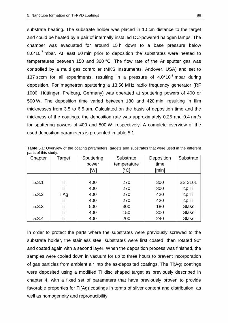
5. Nanotube formation on Ti-PVD coatings 88
substrate heating. The substrate holder was placed in 10 cm distance to the target
and could be heated by a pair of internally installed DC-powered halogen lamps. The
chamber was evacuated for around 15 h down to a base pressure below
8.6*10-7 mbar. At least 60 min prior to deposition the substrates were heated to
temperatures between 150 and 300 °C. The flow rate of the Ar sputter gas was
controlled by a multi gas controller (MKS Instruments, Andover, USA) and set to
137 sccm for all experiments, resulting in a pressure of 4.0*10-3 mbar during
deposition. For magnetron sputtering a 13.56 MHz radio frequency generator (RF
1000, Hüttinger, Freiburg, Germany) was operated at sputtering powers of 400 or
500 W. The deposition time varied between 180 and 420 min, resulting in film
thicknesses from 3.5 to 6.5 µm. Calculated on the basis of deposition time and the
thickness of the coatings, the deposition rate was approximately 0.25 and 0.4 nm/s
for sputtering powers of 400 and 500 W, respectively. A complete overview of the
used deposition parameters is presented in table 5.1.
Table 5.1: Overview of the coating parameters, targets and substrates that were used in the different parts of this study.
Chapter Target Sputtering Substrate Deposition Substrate
power temperature time
[W] [°C] [min]
5.3.1 Ti 400 270 300 SS 316L
Ti 400 270 300 cp Ti
5.3.2 TiAg 400 270 420 cp Ti
Ti 400 270 420 cp Ti
5.3.3 Ti 500 300 180 Glass
Ti 400 150 300 Glass
5.3.4 Ti 400 200 240 Glass
In order to protect the parts where the substrates were previously screwed to the
substrate holder, the stainless steel substrates were first coated, then rotated 90°
and coated again with a second layer. When the deposition process was finished, the
samples were cooled down in vacuum for up to three hours to prevent incorporation
of gas particles from ambient air into the as-deposited coatings. The Ti(Ag) coatings
were deposited using a modified Ti disc shaped target as previously described in
chapter 4, with a fixed set of parameters that have previously proven to provide
favorable properties for Ti(Ag) coatings in terms of silver content and distribution, as
well as homogeneity and reproducibility.
5. Nanotube formation on Ti-PVD coatings 89
5.2.3 Electrochemical anodization
Prior to anodization the PVD-coatings on the metal substrates and the coatings on
the glass substrates of chapter 5.3.3 were at first mechanically polished and
afterwards cleaned in three consecutive ultrasonic baths (Bandelin electronic, Berlin,
Germany) with acetone, isopropanol and ultrapure water, before being dried by
means of compressed air. In the other parts of this study (part 5.3.3 and 5.3.4) the
polishing step was replaced by a short etching step of 60 s in diluted hydrofluoric acid
(0.5 wt%) directly before placing the samples in the electrolyte and the beginning of
the anodization process.
The polished and cleaned coated metal substrates were placed in a custom-made
sample holder, consisting of methacrylate based cement (Technovit 2060, Heraeus-
Kulzer, Germany), in which the samples could be fixed and sealed by a Teflon ring
thereby only exposing the PVD-coated part of the samples. The electric connection
was applied at the backside of the samples via a stainless steel plate embedded in
the Technovit part of the holder. This ensured that only the coated part of the
samples was in contact with the electrolyte. The coated glass slides were only
partially submerged in the electrolyte and could therefore be easily connected
outside of the liquid on the upper part of the samples via a crocodile clamp. A
platinum-coated stainless steel plate was used as counter electrode with a 2 cm
distance to the working electrode. Magnetic stirring was applied to ensure
homogeneity of the electrolyte.
The anodic oxidation was performed in aqueous electrolytes using different mixtures
of diluted acids. The PVD-coatings on the metal substrates and the coatings on the
glass substrates of chapter 5.3.3 were anodized in an aqueous electrolyte containing
sulfuric and hydrofluoric acid of different compositions (0.5 M H2SO4 + 0.06 wt% HF,
1 M H2SO4 + 0.15 wt% HF) [201]. The Ti-PVD coatings on the glass slides of
part 5.3.4 were anodized in a mixture of phosphoric and hydrofluoric acid (1 M
H3PO4 + 0.2 wt% HF) [202]. The anodization was carried out using a DC power
supply (Voltcraft VLP 1602 Pro, Conrad Electronic AG, Wollerau, Swizz). After
submerging the samples in the electrolyte and waiting until a steady state of current
was established, the voltage was continually increased with a rate of 0.1 V/s until the
target value was reached. The anodization time varied between 1 h for the TiAg
coated samples and 5 h for the titanium coatings on cp Ti and the polished stainless
steel substrates. The Ti-coated glass slides were constantly anodized for 2 h. After
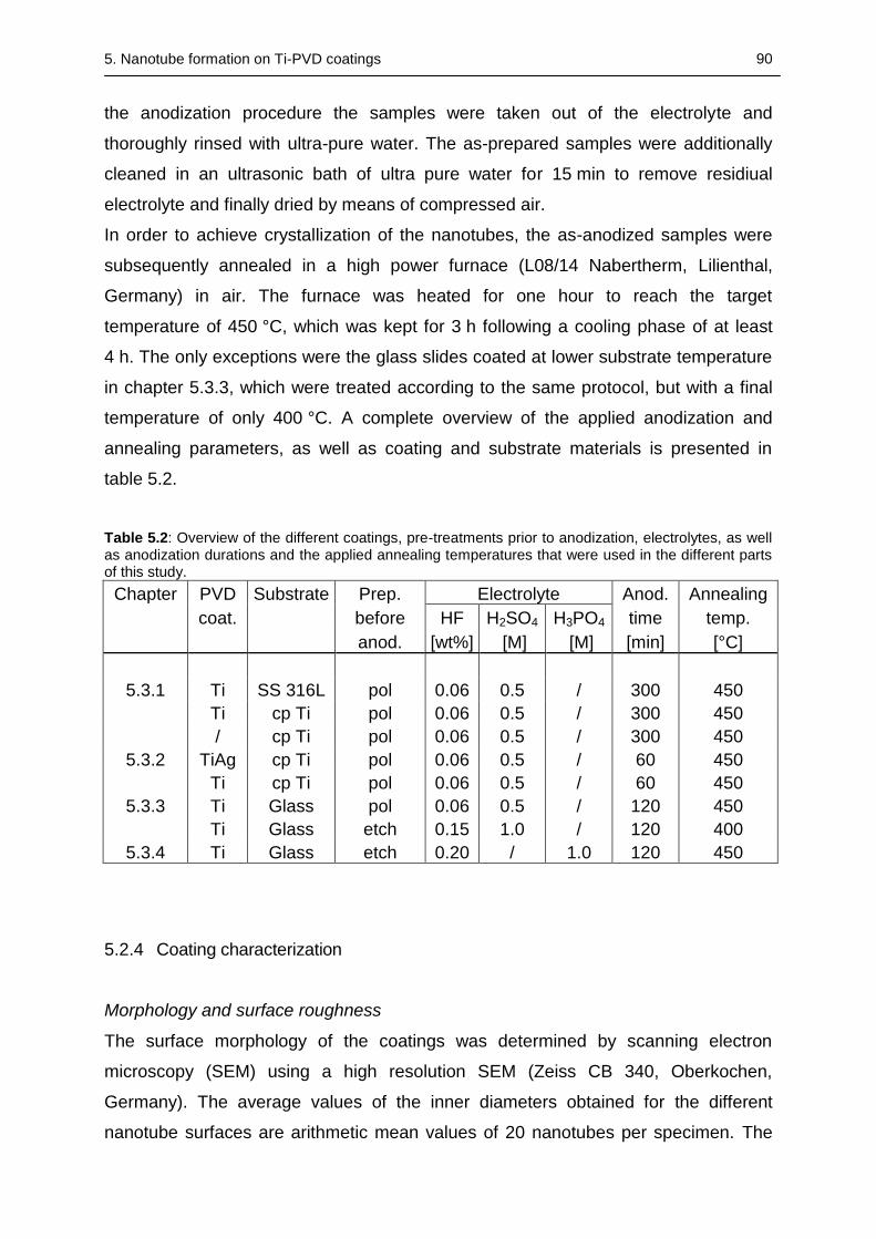
5. Nanotube formation on Ti-PVD coatings 90
the anodization procedure the samples were taken out of the electrolyte and
thoroughly rinsed with ultra-pure water. The as-prepared samples were additionally
cleaned in an ultrasonic bath of ultra pure water for 15 min to remove residiual
electrolyte and finally dried by means of compressed air.
In order to achieve crystallization of the nanotubes, the as-anodized samples were
subsequently annealed in a high power furnace (L08/14 Nabertherm, Lilienthal,
Germany) in air. The furnace was heated for one hour to reach the target
temperature of 450 °C, which was kept for 3 h following a cooling phase of at least
4 h. The only exceptions were the glass slides coated at lower substrate temperature
in chapter 5.3.3, which were treated according to the same protocol, but with a final
temperature of only 400 °C. A complete overview of the applied anodization and
annealing parameters, as well as coating and substrate materials is presented in
table 5.2.
Table 5.2: Overview of the different coatings, pre-treatments prior to anodization, electrolytes, as well as anodization durations and the applied annealing temperatures that were used in the different parts of this study.
Chapter PVD Substrate Prep. Electrolyte Anod. Annealing
coat. before HF H2SO4 H3PO4 time temp.
anod. [wt%] [M] [M] [min] [°C]
5.3.1 Ti SS 316L pol 0.06 0.5 / 300 450
Ti cp Ti pol 0.06 0.5 / 300 450
/ cp Ti pol 0.06 0.5 / 300 450
5.3.2 TiAg cp Ti pol 0.06 0.5 / 60 450
Ti cp Ti pol 0.06 0.5 / 60 450
5.3.3 Ti Glass pol 0.06 0.5 / 120 450
Ti Glass etch 0.15 1.0 / 120 400
5.3.4 Ti Glass etch 0.20 / 1.0 120 450
5.2.4 Coating characterization
Morphology and surface roughness
The surface morphology of the coatings was determined by scanning electron
microscopy (SEM) using a high resolution SEM (Zeiss CB 340, Oberkochen,
Germany). The average values of the inner diameters obtained for the different
nanotube surfaces are arithmetic mean values of 20 nanotubes per specimen. The
5. Nanotube formation on Ti-PVD coatings 91
surface morphology of the PVD coatings as well as the surfaces of the
nanostructured coatings on the glass slides were scanned by atomic force
microscopy (Nanosurf FlexAFM, Nanosurf GmbH, Langen, Germany). Using the
standard instrument software Nanosurf Easyscan 2, the surface roughness was
analyzed and quantitatively measured on the nanometer scale. Line roughness
values were determined at three different positions on the scan fields with a size of
approximately 5 µm x 5 µm. Each sample was analyzed in air under tapping mode,
with a scan speed of 0.3 s/line, using a silicon cantilever Tap190-Al G (Innovative
Solutions Bulgaria Ltd, Sofia, Bulgaria) with a tip radius of about 10 nm or smaller.
XRD
The crystallographic properties of the nanostructured samples were analyzed by
X-ray diffraction (XRD) in grazing angle geometry under an angle of incidence of 2°,
using a Siemens D5005 X-ray diffractometer (Bruker AXS, Karlsruhe, Germany) and
Cu-Kradiation with a voltage of 40 kV and a tube current of 40 mA. The diffraction
patterns recorded in a 2Θ range from 20 - 80° were evaluated with the software
DiffracPlus EVA (Bruker AXS, Karlsruhe, Germany) and compared with reference
patterns from the JCPDS database [288].
Chemical Composition
The chemical composition of the nanostructured Ti(Ag) coatings was analyzed by
means of energy dispersive X-ray spectroscopy (EDX) measurements using an EDX
detector X-Max (Oxford instruments, Abingdon, GB) and the evaluation software
(AZtecEnergy analysis software Oxford instruments, Abingdon, GB).
Contact angle
Surface wettability was determined using a contact angle measuring device (DSA
100, Krüss GmbH, Hamburg, Germany). The freshly prepared samples were cleaned
with isopropanol and dried by compressed air before 3 µl of ultrapure water were
dripped onto the surface. The experiment was repeated three times per sample on
different parts of the surface.
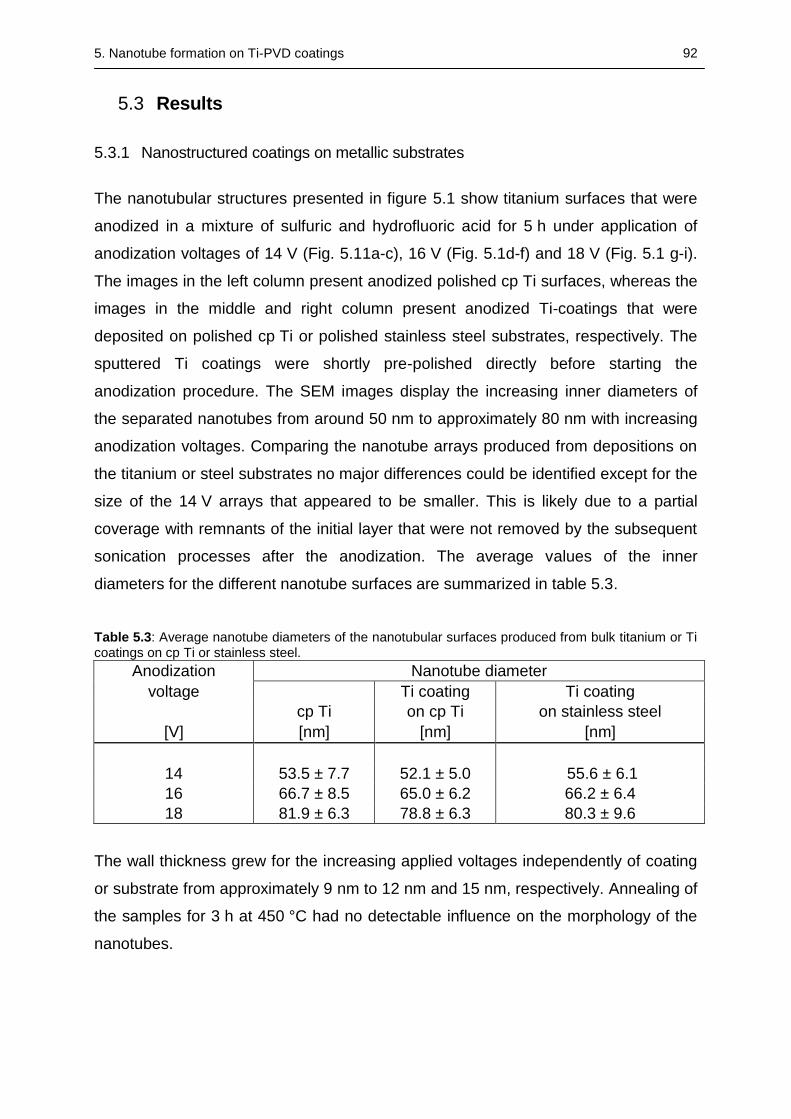
5. Nanotube formation on Ti-PVD coatings 92
5.3 Results
5.3.1 Nanostructured coatings on metallic substrates
The nanotubular structures presented in figure 5.1 show titanium surfaces that were
anodized in a mixture of sulfuric and hydrofluoric acid for 5 h under application of
anodization voltages of 14 V (Fig. 5.11a-c), 16 V (Fig. 5.1d-f) and 18 V (Fig. 5.1 g-i).
The images in the left column present anodized polished cp Ti surfaces, whereas the
images in the middle and right column present anodized Ti-coatings that were
deposited on polished cp Ti or polished stainless steel substrates, respectively. The
sputtered Ti coatings were shortly pre-polished directly before starting the
anodization procedure. The SEM images display the increasing inner diameters of
the separated nanotubes from around 50 nm to approximately 80 nm with increasing
anodization voltages. Comparing the nanotube arrays produced from depositions on
the titanium or steel substrates no major differences could be identified except for the
size of the 14 V arrays that appeared to be smaller. This is likely due to a partial
coverage with remnants of the initial layer that were not removed by the subsequent
sonication processes after the anodization. The average values of the inner
diameters for the different nanotube surfaces are summarized in table 5.3.
Table 5.3: Average nanotube diameters of the nanotubular surfaces produced from bulk titanium or Ti coatings on cp Ti or stainless steel.
Anodization Nanotube diameter
voltage Ti coating Ti coating
cp Ti on cp Ti on stainless steel
[V] [nm] [nm] [nm]
14 53.5 ± 7.7 52.1 ± 5.0 55.6 ± 6.1
16 66.7 ± 8.5 65.0 ± 6.2 66.2 ± 6.4
18 81.9 ± 6.3 78.8 ± 6.3 80.3 ± 9.6
The wall thickness grew for the increasing applied voltages independently of coating
or substrate from approximately 9 nm to 12 nm and 15 nm, respectively. Annealing of
the samples for 3 h at 450 °C had no detectable influence on the morphology of the
nanotubes.
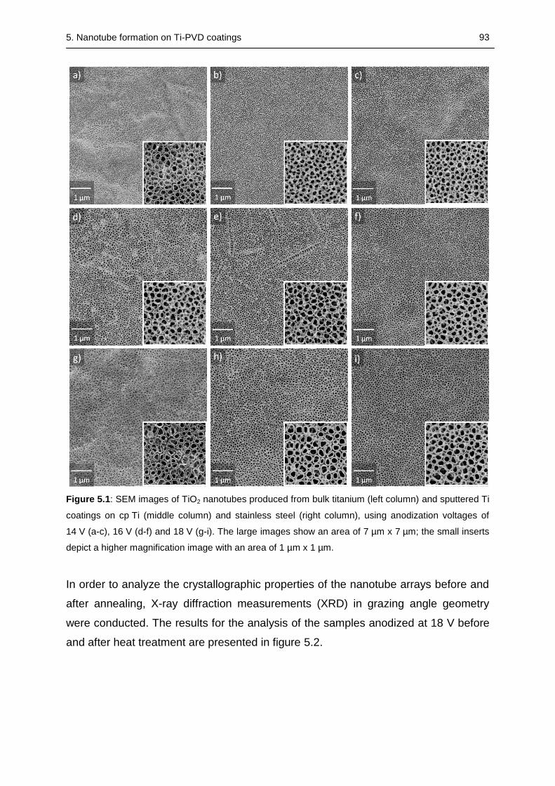
5. Nanotube formation on Ti-PVD coatings 93
Figure 5.1: SEM images of TiO2 nanotubes produced from bulk titanium (left column) and sputtered Ti
coatings on cp Ti (middle column) and stainless steel (right column), using anodization voltages of
14 V (a-c), 16 V (d-f) and 18 V (g-i). The large images show an area of 7 µm x 7 µm; the small inserts
depict a higher magnification image with an area of 1 µm x 1 µm.
In order to analyze the crystallographic properties of the nanotube arrays before and
after annealing, X-ray diffraction measurements (XRD) in grazing angle geometry
were conducted. The results for the analysis of the samples anodized at 18 V before
and after heat treatment are presented in figure 5.2.
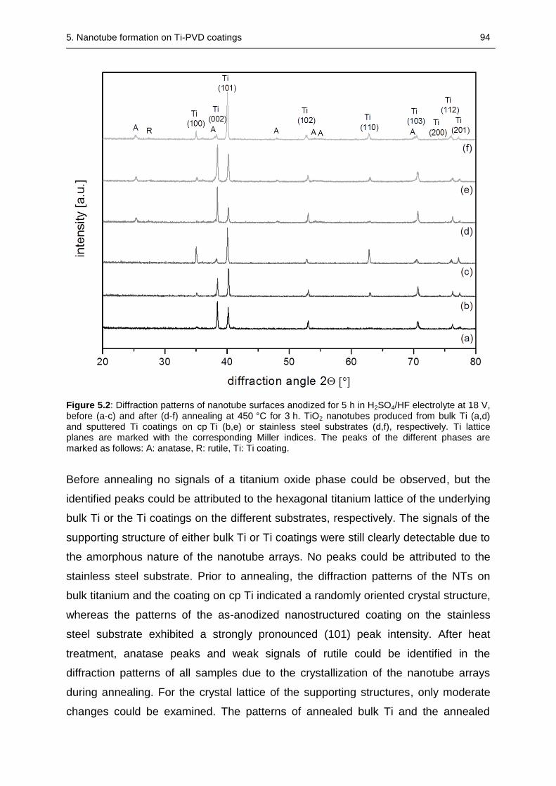
5. Nanotube formation on Ti-PVD coatings 94
Figure 5.2: Diffraction patterns of nanotube surfaces anodized for 5 h in H2SO4/HF electrolyte at 18 V, before (a-c) and after (d-f) annealing at 450 °C for 3 h. TiO2 nanotubes produced from bulk Ti (a,d) and sputtered Ti coatings on cp Ti (b,e) or stainless steel substrates (d,f), respectively. Ti lattice planes are marked with the corresponding Miller indices. The peaks of the different phases are marked as follows: A: anatase, R: rutile, Ti: Ti coating.
Before annealing no signals of a titanium oxide phase could be observed, but the
identified peaks could be attributed to the hexagonal titanium lattice of the underlying
bulk Ti or the Ti coatings on the different substrates, respectively. The signals of the
supporting structure of either bulk Ti or Ti coatings were still clearly detectable due to
the amorphous nature of the nanotube arrays. No peaks could be attributed to the
stainless steel substrate. Prior to annealing, the diffraction patterns of the NTs on
bulk titanium and the coating on cp Ti indicated a randomly oriented crystal structure,
whereas the patterns of the as-anodized nanostructured coating on the stainless
steel substrate exhibited a strongly pronounced (101) peak intensity. After heat
treatment, anatase peaks and weak signals of rutile could be identified in the
diffraction patterns of all samples due to the crystallization of the nanotube arrays
during annealing. For the crystal lattice of the supporting structures, only moderate
changes could be examined. The patterns of annealed bulk Ti and the annealed
5. Nanotube formation on Ti-PVD coatings 95
nanostructured PVD coating on cp Ti showed an increase in signal intensity of the
(002) peak, accompanied by a decrease in intensity of the (101) peak. The diffraction
patterns of the Ti coating on stainless steel presented the same (101) orientation as
prior to annealing.
5.3.2 Nanotubes produced from silver-doped Ti PVD coatings
Figure 5.3 presents SEM images of the Ti(Ag) coatings deposited on polished
titanium discs by RF-magnetron sputtering with a modular target at elevated
substrate temperatures of 270 °C, before and after anodization at different voltages
for 1 h in an electrolyte mixture of H2SO4 and HF. For comparison, together with the
Ti(Ag) based nanotubes a nanotubular structure produced by a one-hour anodization
of an undoped Ti coating using the same electrolyte is presented.
The Ti(Ag) coatings produced by a 7 h sputter deposition on the heated Ti-substrates
exhibited a homogeneous and dense surface. The SEM images display the
increasing inner diameters of the nanotubes by increasing anodization voltage with
average diameters in the range of ~55 nm to ~90 nm (average nanotube diameters
are presented in table 5.4). The smallest nanotubes exhibit wall thicknesses of about
9 nm, whereas the wall thickness grew to an average value of 17 nm for the 20 V
nanotubes. The annealing process had no influence on the morphology of the Ti(Ag)
nanotubes. No major morphological differences between the nanotubes obtained
from silver-doped or undoped Ti-coatings could be identified after one hour
anodization.
Grazing angle XRD measurements were performed to examine the phase
composition of the electrochemically treated silver-doped titanium coatings. The
analysis of the crystallographic structure of the nanostructured Ti(Ag) coatings on
polished Ti discs before and after annealing is presented in Fig. 5.4. The
measurements revealed that the as-anodized nanotube array was amorphous in
phase and only titanium and silver peaks could be identified before annealing. Prior
to annealing all the peaks associated with the hexagonal lattice of titanium could be
identified along with a strong (101) orientation. The Ag (111) peak was clearly visible
at around 38.2 ° before the annealing of the nanotubular samples. The nanotubular
layer was crystallized by annealing at 450 °C for 3 h, and the GAXRD patterns
showed that the nanotube array consisted particularly of TiO2 in the anatas
conformation, while only a very small fraction of the high temperature phase rutile
5. Nanotube formation on Ti-PVD coatings 96
could be identified. In addition to the peaks that could be associated to TiO2, also Ti
and Ag peaks could be identified after annealing whereas the Ag (111) peak could be
hardly distinguished from the growing anatas peak after the annealing step. The
anodization voltage had no major influence on the phase composition of the
nanostructured coatings and no peak could be attributed to the Ti substrate.
The chemical composition of the untreated and nanotubular coatings was determined
by EDX measurements; the results are presented in table 5.4.
Table 5.4: Average nanotube diameters and chemical composition determined by means of EDX measurements of electrochemically treated silver doped titanium coatings with anodization voltages of 14-20 V before and after annealing at 450 °C for 3h. In addition the chemical compositions of an untreated Ti(Ag) coating and an anodized pure titanium coating (NT 20V*) are displayed. The uncertainty of the EDX measurements is at the most ± 0.2 wt%, but in almost all cases below this value.
Sample Nanotube Mass concentration [%]
diameter before annealing after annealing
[nm] Ti O Ag F C Ar Ti O Ag F C
TiAg / 91.5 3.8 0.5 / 3.2 0.8
NT 14 V 55.9 ± 8.6 69.9 23.1 2.4 2.6 1.9 0.0 63.6 30.5 2.5 1.1 2.2
NT 16 V 69.7 ± 10.1 66.2 26.1 2.5 2.9 2.3 0.0 65.5 30.0 2.3 0.0 2.2
NT 18 V 80.6 ± 10.6 65.0 27.1 2.1 3.0 2.7 0.0 64.3 31.4 2.1 0.0 2.2
NT 20 V 90.8 ± 12.8 64.7 27.4 2.3 3.2 2.4 0.0 63.5 32.2 2.2 0.0 2.0
NT 20 V* 90.1 ± 10.9 70.8 24.4 / 3.0 1.9 0.0 66.3 31.4 / 0.0 2.3
The presence of silver in both treated and untreated coatings could be demonstrated.
The relative silver content in the as-deposited coatings was around 0.5 wt% and
increased to values up to 2.5 wt% after the anodization process. Contaminations of
carbon, oxygen and argon could also be detected by investigating the untreated
PVD-coatings. From the EDX measurements it could be seen that prior to calcination
the nanotubular samples contained not only titanium, oxygen and silver as expected,
but also fluoride and carbon. After the annealing process the mass ratio of titanium to
oxygen decreased, whereas the determined silver content and the measured amount
of carbon remained relatively constant. The most significant changes in mass
concentration before and after annealing could be seen with the fluoride content,
which was in almost all cases completely removed. During the different processes
the chemical composition of the undoped nanostructured Ti-coating changed in the
same way as the Ag-doped coatings.
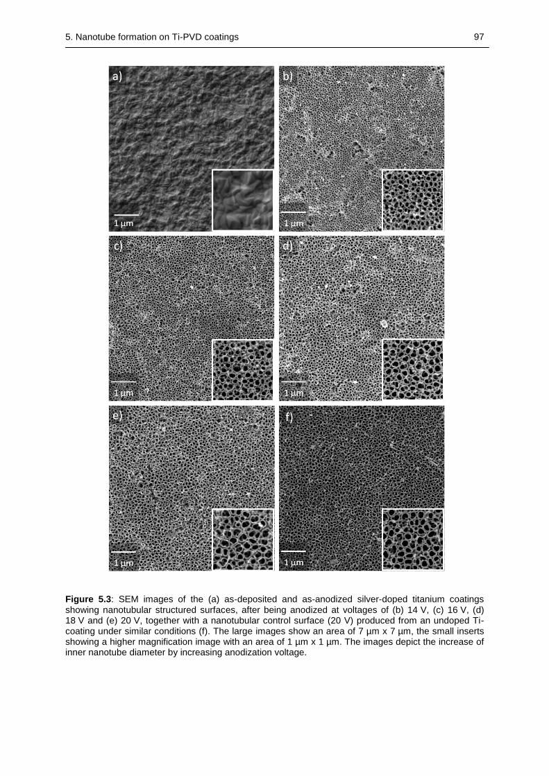
5. Nanotube formation on Ti-PVD coatings 97
Figure 5.3: SEM images of the (a) as-deposited and as-anodized silver-doped titanium coatings showing nanotubular structured surfaces, after being anodized at voltages of (b) 14 V, (c) 16 V, (d) 18 V and (e) 20 V, together with a nanotubular control surface (20 V) produced from an undoped Ti-coating under similar conditions (f). The large images show an area of 7 µm x 7 µm, the small inserts showing a higher magnification image with an area of 1 µm x 1 µm. The images depict the increase of inner nanotube diameter by increasing anodization voltage.
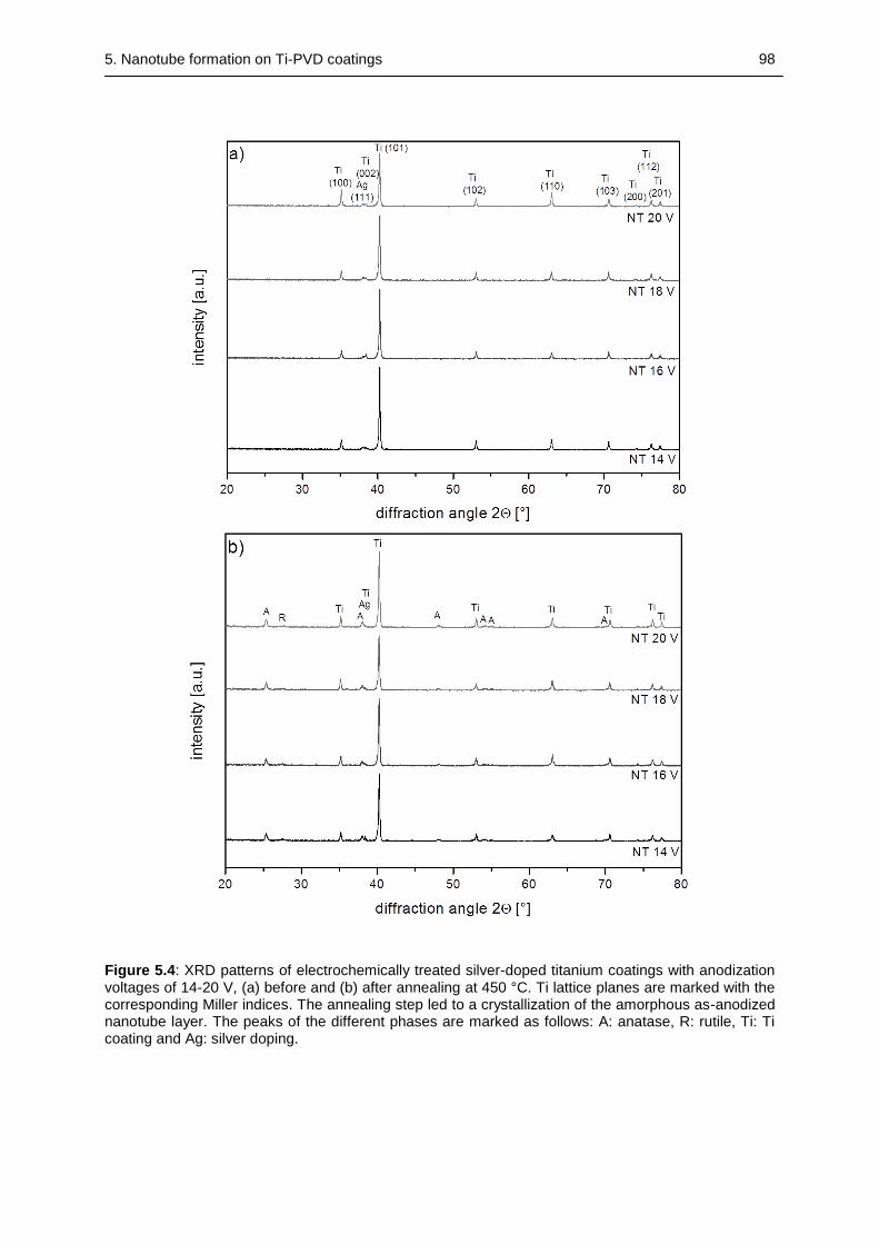
5. Nanotube formation on Ti-PVD coatings 98
Figure 5.4: XRD patterns of electrochemically treated silver-doped titanium coatings with anodization voltages of 14-20 V, (a) before and (b) after annealing at 450 °C. Ti lattice planes are marked with the corresponding Miller indices. The annealing step led to a crystallization of the amorphous as-anodized nanotube layer. The peaks of the different phases are marked as follows: A: anatase, R: rutile, Ti: Ti coating and Ag: silver doping.
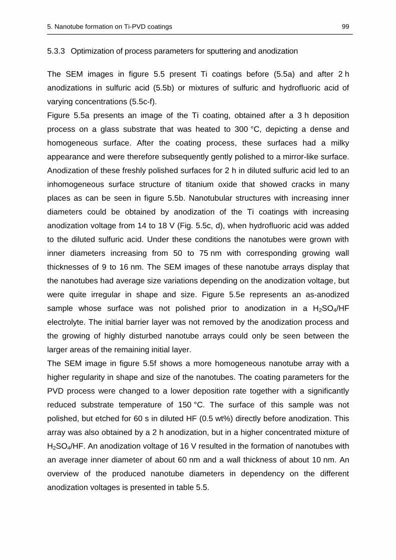
5. Nanotube formation on Ti-PVD coatings 99
5.3.3 Optimization of process parameters for sputtering and anodization
The SEM images in figure 5.5 present Ti coatings before (5.5a) and after 2 h
anodizations in sulfuric acid (5.5b) or mixtures of sulfuric and hydrofluoric acid of
varying concentrations (5.5c-f).
Figure 5.5a presents an image of the Ti coating, obtained after a 3 h deposition
process on a glass substrate that was heated to 300 °C, depicting a dense and
homogeneous surface. After the coating process, these surfaces had a milky
appearance and were therefore subsequently gently polished to a mirror-like surface.
Anodization of these freshly polished surfaces for 2 h in diluted sulfuric acid led to an
inhomogeneous surface structure of titanium oxide that showed cracks in many
places as can be seen in figure 5.5b. Nanotubular structures with increasing inner
diameters could be obtained by anodization of the Ti coatings with increasing
anodization voltage from 14 to 18 V (Fig. 5.5c, d), when hydrofluoric acid was added
to the diluted sulfuric acid. Under these conditions the nanotubes were grown with
inner diameters increasing from 50 to 75 nm with corresponding growing wall
thicknesses of 9 to 16 nm. The SEM images of these nanotube arrays display that
the nanotubes had average size variations depending on the anodization voltage, but
were quite irregular in shape and size. Figure 5.5e represents an as-anodized
sample whose surface was not polished prior to anodization in a H2SO4/HF
electrolyte. The initial barrier layer was not removed by the anodization process and
the growing of highly disturbed nanotube arrays could only be seen between the
larger areas of the remaining initial layer.
The SEM image in figure 5.5f shows a more homogeneous nanotube array with a
higher regularity in shape and size of the nanotubes. The coating parameters for the
PVD process were changed to a lower deposition rate together with a significantly
reduced substrate temperature of 150 °C. The surface of this sample was not
polished, but etched for 60 s in diluted HF (0.5 wt%) directly before anodization. This
array was also obtained by a 2 h anodization, but in a higher concentrated mixture of
H2SO4/HF. An anodization voltage of 16 V resulted in the formation of nanotubes with
an average inner diameter of about 60 nm and a wall thickness of about 10 nm. An
overview of the produced nanotube diameters in dependency on the different
anodization voltages is presented in table 5.5.
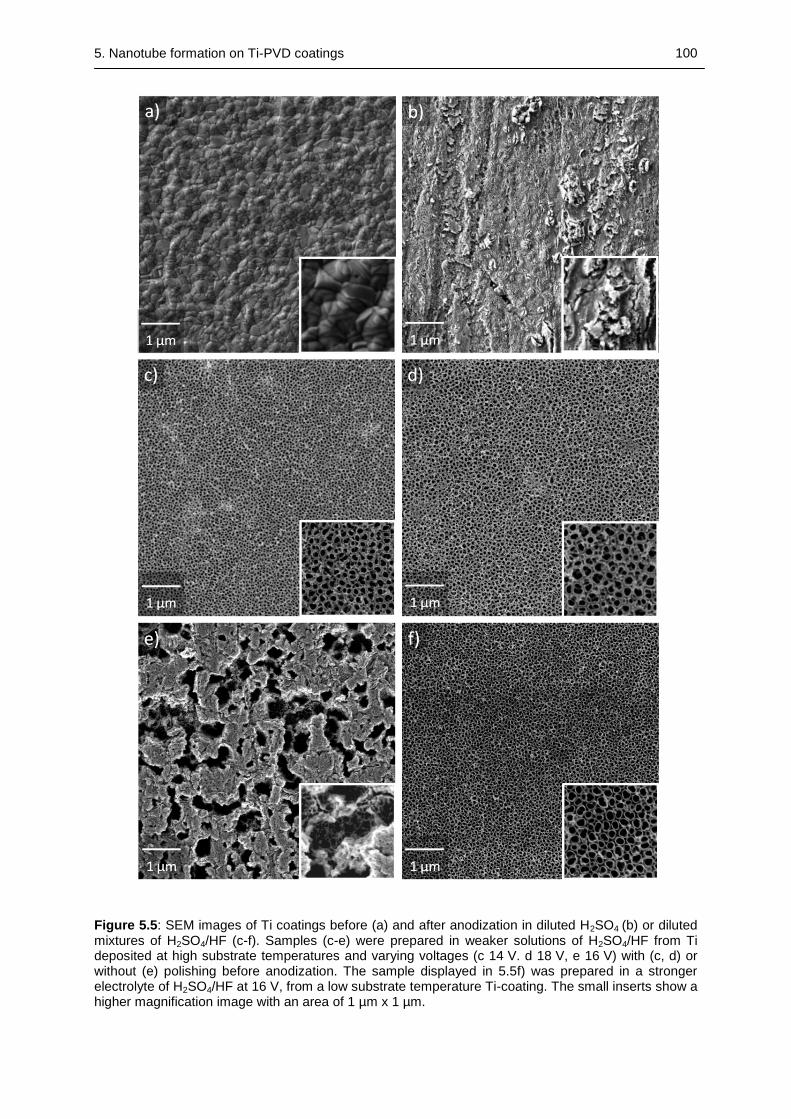
5. Nanotube formation on Ti-PVD coatings 100
Figure 5.5: SEM images of Ti coatings before (a) and after anodization in diluted H2SO4 (b) or diluted mixtures of H2SO4/HF (c-f). Samples (c-e) were prepared in weaker solutions of H2SO4/HF from Ti deposited at high substrate temperatures and varying voltages (c 14 V. d 18 V, e 16 V) with (c, d) or without (e) polishing before anodization. The sample displayed in 5.5f) was prepared in a stronger electrolyte of H2SO4/HF at 16 V, from a low substrate temperature Ti-coating. The small inserts show a higher magnification image with an area of 1 µm x 1 µm.
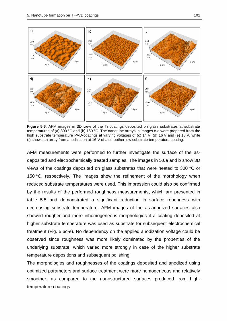
5. Nanotube formation on Ti-PVD coatings 101
Figure 5.6: AFM images in 3D view of the Ti coatings deposited on glass substrates at substrate temperatures of (a) 300 °C and (b) 150 °C. The nanotube arrays in images c-e were prepared from the high substrate temperature PVD-coatings at varying voltages of (c) 14 V, (d) 16 V and (e) 18 V, while (f) shows an array from anodization at 16 V of a smoother low substrate temperature coating.
AFM measurements were performed to further investigate the surface of the as-
deposited and electrochemically treated samples. The images in 5.6a and b show 3D
views of the coatings deposited on glass substrates that were heated to 300 °C or
150 °C, respectively. The images show the refinement of the morphology when
reduced substrate temperatures were used. This impression could also be confirmed
by the results of the performed roughness measurements, which are presented in
table 5.5 and demonstrated a significant reduction in surface roughness with
decreasing substrate temperature. AFM images of the as-anodized surfaces also
showed rougher and more inhomogeneous morphologies if a coating deposited at
higher substrate temperature was used as substrate for subsequent electrochemical
treatment (Fig. 5.6c-e). No dependency on the applied anodization voltage could be
observed since roughness was more likely dominated by the properties of the
underlying substrate, which varied more strongly in case of the higher substrate
temperature depositions and subsequent polishing.
The morphologies and roughnesses of the coatings deposited and anodized using
optimized parameters and surface treatment were more homogeneous and relatively
smoother, as compared to the nanostructured surfaces produced from high-
temperature coatings.
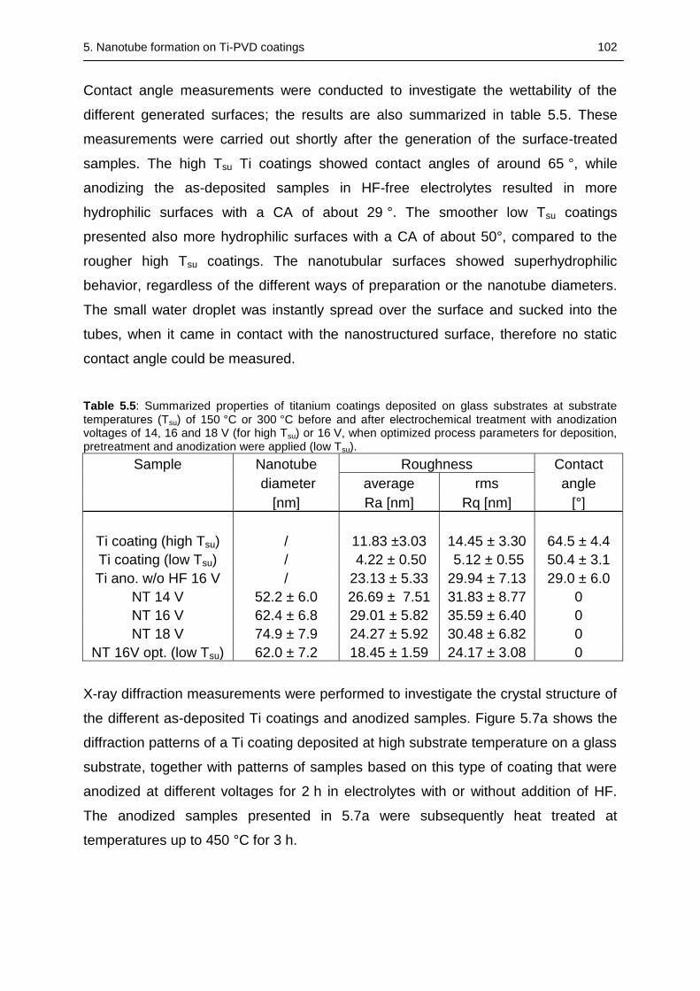
5. Nanotube formation on Ti-PVD coatings 102
Contact angle measurements were conducted to investigate the wettability of the
different generated surfaces; the results are also summarized in table 5.5. These
measurements were carried out shortly after the generation of the surface-treated
samples. The high Tsu Ti coatings showed contact angles of around 65 °, while
anodizing the as-deposited samples in HF-free electrolytes resulted in more
hydrophilic surfaces with a CA of about 29 °. The smoother low Tsu coatings
presented also more hydrophilic surfaces with a CA of about 50°, compared to the
rougher high Tsu coatings. The nanotubular surfaces showed superhydrophilic
behavior, regardless of the different ways of preparation or the nanotube diameters.
The small water droplet was instantly spread over the surface and sucked into the
tubes, when it came in contact with the nanostructured surface, therefore no static
contact angle could be measured.
Table 5.5: Summarized properties of titanium coatings deposited on glass substrates at substrate temperatures (Tsu) of 150 °C or 300 °C before and after electrochemical treatment with anodization voltages of 14, 16 and 18 V (for high Tsu) or 16 V, when optimized process parameters for deposition, pretreatment and anodization were applied (low Tsu).
Sample Nanotube Roughness Contact
diameter average rms angle
[nm] Ra [nm] Rq [nm] [°]
Ti coating (high Tsu) / 11.83 ±3.03 14.45 ± 3.30 64.5 ± 4.4
Ti coating (low Tsu) / 4.22 ± 0.50 5.12 ± 0.55 50.4 ± 3.1
Ti ano. w/o HF 16 V / 23.13 ± 5.33 29.94 ± 7.13 29.0 ± 6.0
NT 14 V 52.2 ± 6.0 26.69 ± 7.51 31.83 ± 8.77 0
NT 16 V 62.4 ± 6.8 29.01 ± 5.82 35.59 ± 6.40 0
NT 18 V 74.9 ± 7.9 24.27 ± 5.92 30.48 ± 6.82 0
NT 16V opt. (low Tsu) 62.0 ± 7.2 18.45 ± 1.59 24.17 ± 3.08 0
X-ray diffraction measurements were performed to investigate the crystal structure of
the different as-deposited Ti coatings and anodized samples. Figure 5.7a shows the
diffraction patterns of a Ti coating deposited at high substrate temperature on a glass
substrate, together with patterns of samples based on this type of coating that were
anodized at different voltages for 2 h in electrolytes with or without addition of HF.
The anodized samples presented in 5.7a were subsequently heat treated at
temperatures up to 450 °C for 3 h.
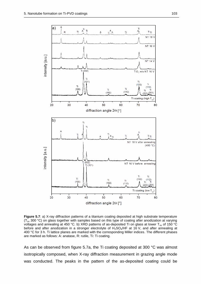
5. Nanotube formation on Ti-PVD coatings 103
Figure 5.7: a) X-ray diffraction patterns of a titanium coating deposited at high substrate temperature (Tsu 300 °C) on glass together with samples based on this type of coating after anodization at varying voltages and annealing at 450 °C. b) XRD patterns of as-deposited Ti on glass at lower Tsu of 150 °C before and after anodization in a stronger electrolyte of H2SO4/HF at 16 V, and after annealing at 400 °C for 3 h. Ti lattice planes are marked with the corresponding Miller indices. The different phases are marked as follows: A: anatase, R: rutile, Ti: Ti coating.
As can be observed from figure 5.7a, the Ti coating deposited at 300 °C was almost
isotropically composed, when X-ray diffraction measurement in grazing angle mode
was conducted. The peaks in the pattern of the as-deposited coating could be
5. Nanotube formation on Ti-PVD coatings 104
associated with the hexagonal titanium lattice and all peaks could be identified
without any strongly preferred orientation. The as-anodized coatings were heat
treated at 450 °C for 3 h in order to crystallize the previously amorphous samples,
which transformed the crystal lattice particularly into an anatase structure. Only very
few traces of rutile could be identified in the nanotubular arrays; the highest fraction
of rutile could be observed for the TiO2 surface without nanotubes. The intensity of
the signals associated with the underlying leftover titanium coating decreased with
increasing anodization voltage, whereas the intensity of the anatase peaks was
found to be independent of anodization voltage. The anatase peak at 38 ° could only
be clearly identified for the sample anodized at 18 V, otherwise this peak led to a
broadening of the Ti (002) peak. Figure 5.7b presents the diffraction patterns of the
coating deposited at lower substrate temperature together with the patterns of the
sample after anodization at 16 V for 2 h before and after annealing at 400 °C for 3 h.
The XRD patterns of the as-deposited coatings showed a random crystallite
orientation and the as-anodized nanotubular surface were amorphous. The annealing
temperature for the nanotube arrays based on the low substrate temperature
coatings had to be decreased to 400 °C, since otherwise the nanotube arrays were
damaged during the annealing process. After annealing only Ti peaks associated to
the supporting leftover titanium coating or anatase peaks could be identified.
5.3.4 Nanotubular structured Ti coatings produced using H3PO4/HF electrolytes
Based on the results of the previous study a new set of nanostructured coatings was
prepared. In figure 5.8, SEM images of Ti coatings on glass slides are presented
before and after electrochemical treatment. Figure 5.1a depicts the dense surface of
an untreated titanium coating produced by a 4 h deposition on a glass substrate,
which was heated to 200 °C. The figures 5.1b-d display the coatings after 2 h
anodization in an electrolyte containing phosphoric and hydrofluoric acid (1M H3PO4
+ 0.2 wt% HF) with increasing anodization voltages. The nanotubes generated with
increasing voltages of 10, 15 and 20 V showed also increasing average inner
diameters of 49, 66 and 88 nm, respectively. The wall thicknesses of the well defined
nanotubes were also growing with increasing anodization voltages from around 9 nm
for the smallest nanotubes at 10 V to around 15 nm for the largest diameter
nanotubes anodized at 20 V.
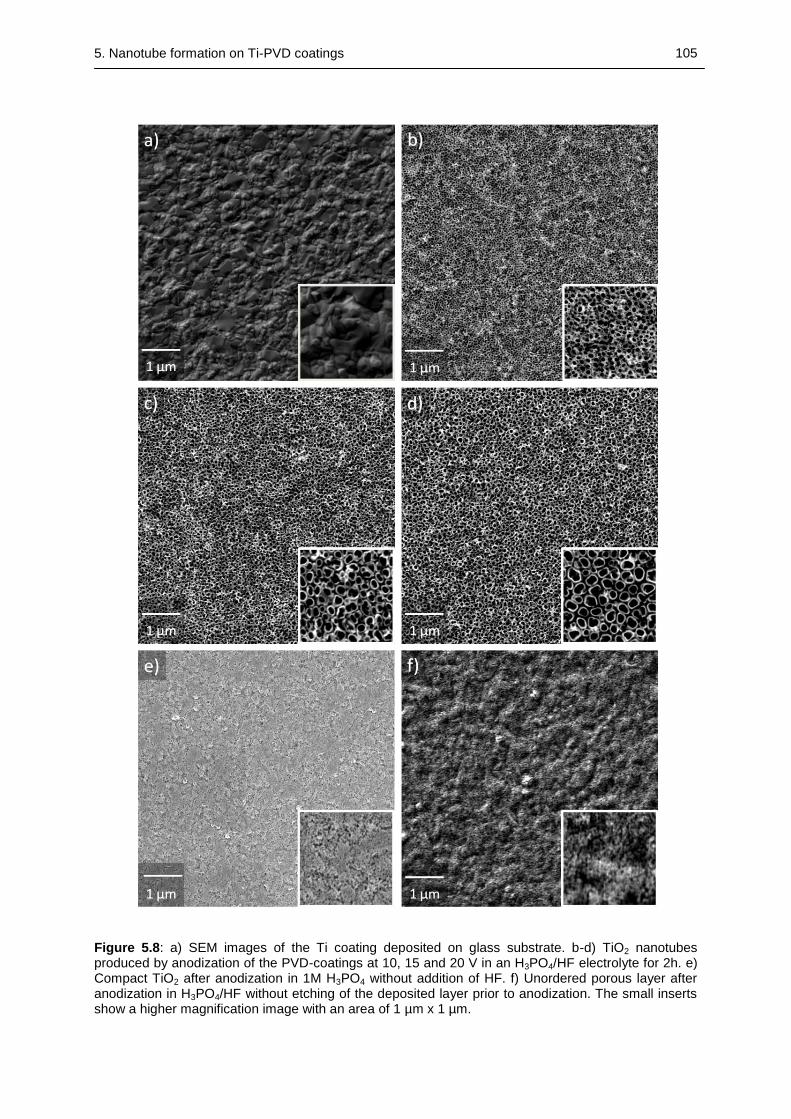
5. Nanotube formation on Ti-PVD coatings 105
Figure 5.8: a) SEM images of the Ti coating deposited on glass substrate. b-d) TiO2 nanotubes produced by anodization of the PVD-coatings at 10, 15 and 20 V in an H3PO4/HF electrolyte for 2h. e) Compact TiO2 after anodization in 1M H3PO4 without addition of HF. f) Unordered porous layer after anodization in H3PO4/HF without etching of the deposited layer prior to anodization. The small inserts show a higher magnification image with an area of 1 µm x 1 µm.
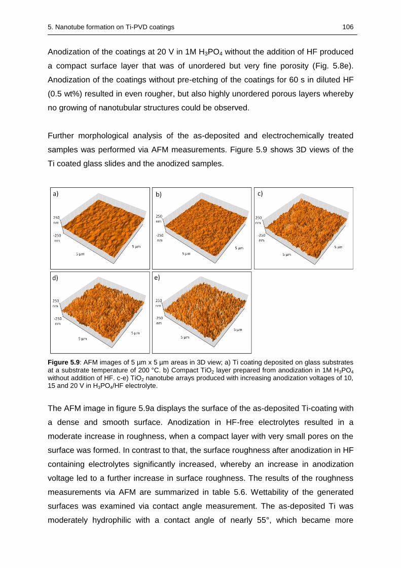
5. Nanotube formation on Ti-PVD coatings 106
Anodization of the coatings at 20 V in 1M H3PO4 without the addition of HF produced
a compact surface layer that was of unordered but very fine porosity (Fig. 5.8e).
Anodization of the coatings without pre-etching of the coatings for 60 s in diluted HF
(0.5 wt%) resulted in even rougher, but also highly unordered porous layers whereby
no growing of nanotubular structures could be observed.
Further morphological analysis of the as-deposited and electrochemically treated
samples was performed via AFM measurements. Figure 5.9 shows 3D views of the
Ti coated glass slides and the anodized samples.
Figure 5.9: AFM images of 5 µm x 5 µm areas in 3D view; a) Ti coating deposited on glass substrates at a substrate temperature of 200 °C. b) Compact TiO2 layer prepared from anodization in 1M H3PO4 without addition of HF. c-e) TiO2 nanotube arrays produced with increasing anodization voltages of 10, 15 and 20 V in H3PO4/HF electrolyte.
The AFM image in figure 5.9a displays the surface of the as-deposited Ti-coating with
a dense and smooth surface. Anodization in HF-free electrolytes resulted in a
moderate increase in roughness, when a compact layer with very small pores on the
surface was formed. In contrast to that, the surface roughness after anodization in HF
containing electrolytes significantly increased, whereby an increase in anodization
voltage led to a further increase in surface roughness. The results of the roughness
measurements via AFM are summarized in table 5.6. Wettability of the generated
surfaces was examined via contact angle measurement. The as-deposited Ti was
moderately hydrophilic with a contact angle of nearly 55°, which became more
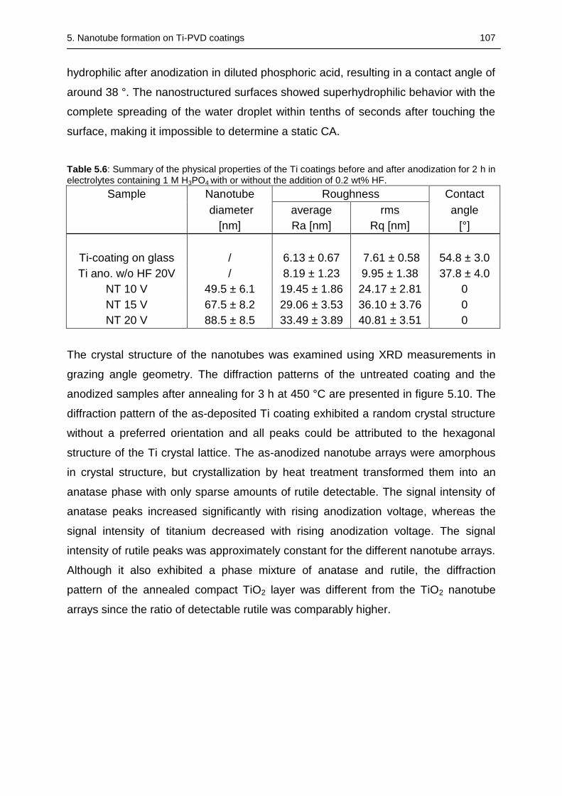
5. Nanotube formation on Ti-PVD coatings 107
hydrophilic after anodization in diluted phosphoric acid, resulting in a contact angle of
around 38 °. The nanostructured surfaces showed superhydrophilic behavior with the
complete spreading of the water droplet within tenths of seconds after touching the
surface, making it impossible to determine a static CA.
Table 5.6: Summary of the physical properties of the Ti coatings before and after anodization for 2 h in electrolytes containing 1 M H3PO4 with or without the addition of 0.2 wt% HF.
Sample Nanotube Roughness Contact
diameter average rms angle
[nm] Ra [nm] Rq [nm] [°]
Ti-coating on glass / 6.13 ± 0.67 7.61 ± 0.58 54.8 ± 3.0
Ti ano. w/o HF 20V / 8.19 ± 1.23 9.95 ± 1.38 37.8 ± 4.0
NT 10 V 49.5 ± 6.1 19.45 ± 1.86 24.17 ± 2.81 0
NT 15 V 67.5 ± 8.2 29.06 ± 3.53 36.10 ± 3.76 0
NT 20 V 88.5 ± 8.5 33.49 ± 3.89 40.81 ± 3.51 0
The crystal structure of the nanotubes was examined using XRD measurements in
grazing angle geometry. The diffraction patterns of the untreated coating and the
anodized samples after annealing for 3 h at 450 °C are presented in figure 5.10. The
diffraction pattern of the as-deposited Ti coating exhibited a random crystal structure
without a preferred orientation and all peaks could be attributed to the hexagonal
structure of the Ti crystal lattice. The as-anodized nanotube arrays were amorphous
in crystal structure, but crystallization by heat treatment transformed them into an
anatase phase with only sparse amounts of rutile detectable. The signal intensity of
anatase peaks increased significantly with rising anodization voltage, whereas the
signal intensity of titanium decreased with rising anodization voltage. The signal
intensity of rutile peaks was approximately constant for the different nanotube arrays.
Although it also exhibited a phase mixture of anatase and rutile, the diffraction
pattern of the annealed compact TiO2 layer was different from the TiO2 nanotube
arrays since the ratio of detectable rutile was comparably higher.
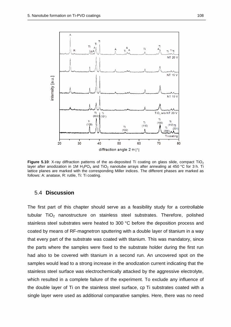
5. Nanotube formation on Ti-PVD coatings 108
Figure 5.10: X-ray diffraction patterns of the as-deposited Ti coating on glass slide, compact TiO2 layer after anodization in 1M H3PO4 and TiO2 nanotube arrays after annealing at 450 °C for 3 h. Ti lattice planes are marked with the corresponding Miller indices. The different phases are marked as follows: A: anatase, R: rutile, Ti: Ti coating.
5.4 Discussion
The first part of this chapter should serve as a feasibility study for a controllable
tubular TiO2 nanostructure on stainless steel substrates. Therefore, polished
stainless steel substrates were heated to 300 °C before the deposition process and
coated by means of RF-magnetron sputtering with a double layer of titanium in a way
that every part of the substrate was coated with titanium. This was mandatory, since
the parts where the samples were fixed to the substrate holder during the first run
had also to be covered with titanium in a second run. An uncovered spot on the
samples would lead to a strong increase in the anodization current indicating that the
stainless steel surface was electrochemically attacked by the aggressive electrolyte,
which resulted in a complete failure of the experiment. To exclude any influence of
the double layer of Ti on the stainless steel surface, cp Ti substrates coated with a
single layer were used as additional comparative samples. Here, there was no need
5. Nanotube formation on Ti-PVD coatings 109
for an absolutely complete protection of the sample surface against a possible
contact with the electrolyte, since substrate and coating material were identical.
Although the two spots on the disc edges, where the Ti substrates were fixed to the
holder during the PVD process, were left uncoated, no changes in the anodization
behavior (current flow) were noticed during the experiments.
The coating procedure was followed by a 5 h anodization in a H2SO4/HF electrolyte
using voltages of 14,16, and 18 V. Polished uncoated cp Ti substrates and polished
cp Ti substrates with additional PVD Ti coating were used as comparative samples
and anodized using the same protocol. The morphology and crystallographic
properties of the produced nanotube arrays, before and after annealing at 450 °C for
3 h, were examined by means of SEM and XRD. With these preparations, a
successful anodization of the different uncoated and especially coated stainless steel
samples was achieved without harming the substrates even in 5 h anodization
experiments. The increase of the inner diameter of the nanotubes that was indicated
by the SEM investigations of the nanotube arrays was found to correlate almost
linearly with the increasing anodization voltage. The diameters of the nanotubes
produced in this range of applied voltages were in well accordance with the
diameters published by other groups using electrolyte mixtures of H2SO4/HF, even if
the concentration of sulfuric and hydrofluoric acid was lower [316]. SEM
investigations could further demonstrate that the nanotubes produced on the
stainless steel substrates were comparable in size and shape to nanotubes produced
under the same electrochemical conditions on bulk titanium and also to the
nanotubular structured coatings on cp Ti.
XRD measurements revealed clear differences between the crystallographic
properties of the as-anodized coated stainless steel samples and the two as-
anodized samples of either uncoated or coated Ti. The diffraction patterns of the as-
anodized uncoated and coated Ti showed no significant differences before
annealing, and all detectable signals could be attributed to the titanium hcp lattice.
The crystal structure of the Ti coating on stainless steel was not isotropic but showed
a stronger (101) orientation. This could be attributed to the influence of the steel
substrate and the increased thickness of the coating. The thickness of the coating
5. Nanotube formation on Ti-PVD coatings 110
and the grazing angle measurement geometry were also responsible for the fact that
no signal from the components of stainless steel could be detected.
The diffraction patterns additionally revealed that the as-prepared ordered nanotube
arrays were amorphous after anodization but were successfully crystallized during
thermal treatment, particularly into the anatase phase with only traces of detectable
rutile. This phase composition was also observed by other groups using this
annealing temperature [209]. The direct comparison between the different samples
after the heat treatment revealed no differences regarding the signal intensities
attributed to the different TiO2 phases. Since the anatase phase could be particularly
attributed to the nanotube structure while the rutile signal could be attributed to a
small interface layer between the nanotube layer and the remaining metallic
substrate, it could be concluded that there was neither a significant difference in the
morphology nor a detectable difference in the crystallographic properties of the
nanotube arrays [184]. An almost exactly equal signal intensity of detected anatase
phase could also indicate a comparable length of the nanotubes since the nanotube
array cover a similar tube diameter and were heat-treated the same way [317]. The
observed differences in the diffraction patterns between the samples were due to
different crystallographic properties of the underlying bulk substrates or coatings and
thus would not influence the cellular behavior on the crystallographically equal
nanotube layers [29], [318].
The comparison of nanotubular structures on stainless steel with nanostructured
coatings on cp Ti substrates could therefore reveal an influence of the substrate on
the crystal structure of the PVD layers; however, there was no detectable influence
on the morphology and the phase composition of the nanotube arrays, which were
successfully converted to the anatase structure by thermal treatment. It could
therefore be concluded that comparable nanotube structures can be created
regardless of the substrate, when the same parameters for deposition and
electrochemical anodization are being applied. Important preconditions for this are (1)
comparable surface roughness, which was in this study achieved by polishing all the
substrates to mirror-like appearance and (2) a suitable resistance against heat to
endure the coating and annealing processes.
5. Nanotube formation on Ti-PVD coatings 111
In the second part of the study, the possibility of creating a nanotubular structured
surface of Ti(Ag) by electrochemical treatment in a fluoride containing electrolyte was
investigated. The Ti(Ag) layers were deposited by means of RF-magnetron sputtering
and were examined after anodization and before/after heat treatment regarding their
morphology, contact angle, crystallographic properties, and chemical composition.
The investigations of the morphology of the anodized coatings by SEM could clearly
depict the evolution of nanotube arrays with separated nanotubes for all different
anodization voltages. The nanotube diameter increased almost linearly with the
increasing anodization voltage. The determined average inner diameters of the
Ti(Ag) nanotubes were in the same range as for nanotubes from pure Ti coatings
obtained by the same coating and anodization parameters. The nanotube diameters
and determined wall thicknesses were also in good accordance with the geometrical
properties produced in section 5.3.1, although the anodization time was only 1 h
instead of 5 h. This clearly indicates that anodization time had no influence on the
diameter of the nanotubes. The diffraction patterns of the nanostructured coatings
showed a sharp peak referring to a strong (101) orientation of the titanium-silver
coating underneath the amorphous nanotubular layer. All detectable peaks prior to
annealing could be attributed to the unchanged PVD-coating, which was particularly
responsible for the obtained diffractograms due to the limited thickness and
amorphous phase of the nanotube array. Apparently, the sharp peak resulted from
the elevated substrate temperature during the PVD coating process, and also the
preferred (101) orientation was in good accordance with the diffraction patterns
observed for Ti(Ag) coatings produced in former studies but with another PVD
coating system and setup [290]. The strong (010) orientation and therefore weak
signal of the (002) peak made it also possible to identify the Ag (111) peak, which is
otherwise only hard to distinguish from the (002) signal of Ti. The existence of this Ag
peak could also be attributed to the accumulation of Ag in the surface near regions of
the coatings due to the elevated substrate temperatures during deposition.
Annealing of the samples at a temperature of 450 °C for 3 h led to the crystallization
of the nanotube array and resulted in the formation of an anatase phase typical for
this annealing temperature [207]. In addition to the anatase peaks, also weak signals
of rutile could be identified, but this has also been observed in other studies at this
5. Nanotube formation on Ti-PVD coatings 112
temperature [192]. The growing of the anatase peaks was accompanied by a slight
decrease of the signals from the underlying Ti(Ag) coating. This could be explained
by an oxidation and crystallization of the surface-near parts of the coating under the
annealed nanotube array, whereby these thermally oxidized parts of the coating may
also have been responsible for the small amount of detected rutile growing at the
interface between the metallic part of the coating and the barrier layer [165].
Comparing the phase composition of the nanostructured coatings obtained by the
different anodization voltages, no major differences could be identified and therefore
it was concluded that anodization voltages in this range had no major influence on
the resulting phase composition before and after annealing.
The mass concentration of silver in the as-deposited Ti(Ag) coatings was in good
accordance to the determined concentration of silver detected by EDX in former
studies (see chapter 4), when substrate heating was applied for the PVD process,
despite the fact that a different PVD system was used and coating parameters like
gas pressure or target-to-substrate distance were varied. The determined silver
content therefore seemed to be predominately influenced by the target design and
the elevated substrate temperature in the PVD device. It could be assumed that the
total concentration of silver was higher than the EDX results indicated. In the
previous study (see chapter 4) a significantly higher total concentration of silver could
be determinded by ICP-MS measurements of completely dissolved Ti(Ag) layers that
were deposited using substrate heating [290]. These coating conditions led to an
accumulation of silver in the surface-near regions of the coatings, which could not be
detected by EDX measurements, since EDX is not as surface sensitive as for
example XPS. The inhomogeneous distribution of silver was attributed to the volume
diffusion of silver in the growing coating, which was possible due to its lower melting
point and lower surface energy compared to titanium [125], [294], [295]. The detected
concentrations of argon, carbon and oxygen in the as-deposited layer were
contaminations that were either incorporated during the deposition process, as e.g.
argon that was used as sputtering gas, or adsorbed on the samples in the time
between coating and EDX measurement.
The concentration of silver as determined by the EDX investigations increased for all
the samples after the anodization process to values between 2.0 and 2.5 wt%. One
5. Nanotube formation on Ti-PVD coatings 113
possible reason for this effect could be the selective dissolution of titanium and thus
an accumulation of silver in the nanotube arrays during the anodization process.
Another explanation could be that silver from the silver-rich surface near part of the
PVD-coating was redistributed during the anodization process. Regarding the atomic
masses of titanium and oxygen, the mass ratio m(Ti)/m(O2) of a perfect anatase
structure should be around 3:2. The EDX measurement gave a result of about 3:1
before and approximately 2:1 after the annealing step. The increased fraction of
detected titanium indicates that EDX measurements not just detected the thin
nanotube layer, which was only a few hundred nanometers in thickness but also
measurered the underlying Ti(Ag) coating. This means also that the determined
amount of silver, which remained approximately constant before and after the
annealing step, could not be completely attributed to the nanostructured part of the
coating only but also to the underlying coating.
The decreasing ratio of m(Ti)/m(O2) after the annealing process could be attributed to
the oxidation and crystallization of the Ti(Ag) coating that supported the
nanostructured uppermost part of the coating. The observed carbon content before
and after annealing may have been due to contaminations from ambient air;
alternatively, carbon could also have been trapped in the layers during the PVD
coating process. Fluorine was also present in the as-anodized amorphous
nanostructured surfaces as it was incorporated during the anodization process. The
amount of fluorine was significantly reduced or, except for the sample anodized at
14 V, completely removed from the layer after the annealing step. Regonini et. al
attributed the fluoride contamination to the incorporation of TiF6- species during
anodization, which are expelled from the nanotubular film during the annealing
process above 400 °C [208]. This could also be demonstrated by Bai et al. who
demonstrated that the residual fluoride in the as-formed non-anodized nanotubes
had initially a negative influence on the cell proliferation rate, which improved after
annealing due to removal of fluoride ions from the nanotube array [228].
The third part of this chapter was focused on identifying factors that are important for
the morphology and properties of nanotube arrays obtained by electrochemical
anodization of Ti-PVD-coatings on glass in aqueous HF-containing electrolytes.
Optimizing process parameters for deposition, pretreatment, anodization, and
annealing should provide information to create more homogeneous surfaces that are
5. Nanotube formation on Ti-PVD coatings 114
in addition easier to reproduce and therefore more suitable for larger sample
numbers.
The as-deposited titanium coatings fabricated with higher substrate temperatures and
sputtering power had a shiny surface with a slightly milky sheen. The coatings
deposited with lower sputtering power, but longer deposition times and decreased
substrate temperature, had a mirror-like appearance. The milky sheen was probably
due to a combination of surface oxidation and increased roughness as indicated by
AFM measurements. This surface layer was found to be detrimental for a subsequent
anodization, as can be seen from the SEM image in figure 5.5e, where no additional
surface treatment was performed prior to anodization. However, this impeding
surface layer could be easily removed by a polishing step; afterwards the coatings
could be successfully used for producing nanotube arrays in a weak electrolyte
mixture of sulfuric and hydrofluoric acid, with increasing diameters when increasing
anodization voltages were applied. The nanotubes obtained by this procedure were
quite irregular in size and shape, which was attributed to the initial roughness and
oxidation of the as-deposited coatings that made the polishing step necessary. An
approach to decrease the initial roughness was found in the reduction of the
deposition time, while maintaining the other parameters such as high substrate
temperature and deposition rate (data not shown). Nevertheless, a polishing step
was necessary to generate surfaces suitable for achieving nanotubular structures,
which despite the decreasing initial roughness of the coatings were still very
inhomogeneous and unordered (data not shown). Furthermore, a short etching step
in diluted hydrofluoric acid was tested as an optional method to remove the initial
surface layer in order to replace the polishing procedure. Etching for a defined period
had the advantage that it was easier to reproduce and in comparison to polishing
would be even suitable for more complex geometries, but in this case it did not
improve the regularity of the nanotube arrays (data not shown). The two particular
steps that really improved the regularity of the generated nanotube arrays were on
one hand the optimization of the deposition parameters by reducing substrate
temperature and deposition rate, which led to a refinement of the morphology of the
coatings, and on the other hand increasing the concentration of sulfuric and
hydrofluoric acid in the electrolyte. Although these changes already led individually to
an improvement in regularity of the nanotubes, combining both modifications resulted
5. Nanotube formation on Ti-PVD coatings 115
in an even higher size and shape regularity of the nanotube arrays generated from
aqueous H2SO4/HF electrolytes.
The Ti coatings obtained from the low substrate temperature deposition already had
a mirror-like surface in comparison to the slightly milky appearance of the high
substrate temperature coatings. Due to the reasons described above, the polishing
step was replaced by a 60 s etching step in diluted hydrofluoric acid to remove the
still remaining thin oxide layer. This pre-etching step was still advantageous, since
otherwise parts of the remaining initial layer could be found on the surface and the
regularity of the size and shape of the tubes was lower. This could also be attributed
to the generation of surface pits through the pre-etching; these pits could act as
nucleation sites and favor the formation of nanotubes [319]. The difference in the Ti-
coatings prepared at high or low substrate temperatures could be demonstrated by
AFM images and roughness measurements, which clearly displayed the transition
from a coarse and large-grained to a very smooth and fine-grained surface texture.
This change in surface texture resulted in a significantly reduced roughness that was
favorable for the production of more regular and ordered nanotube arrays as also
demonstrated by Farsinezhad et al. [320]. The roughness of the nanotube arrays
increased for all the electrochemically treated samples compared to the as-deposited
coatings, but it was particularly depending on the PVD coating parameters and the
pretreatment, but not on the parameters of the anodization process such as
anodization voltage. The measured roughness values of the nanostructured coatings
have to be regarded critically, since the nanoroughness was superimposed on the
roughness of the underlying pretreated PVD-coating. A further aspect is that the
radius of the probe tip, especially when already previously used, was in the same
dimensional order than the pore openings, which together with the substrate
roughness additionally complicated the measurement [54]. Differences in nanotube
roughness depending on process parameters such as anodization voltage may
therefore be easier identified using smoother substrates combined with a well-defined
pretreatment.
The wettability of biomaterial surfaces is important because of its influence on cell
adhesion and protein adsorption; higher surface hydrophilicity can have a stimulating
effect on hard and soft tissue integration of an implant [321]. Wettability was therefore
determined by contact angle measurements, which demonstrated a significant
5. Nanotube formation on Ti-PVD coatings 116
enhancement of surface wettability compared to the as-deposited coatings. These
tests were performed shortly after the generation of the different samples, since an
extended time span between production and measurement would have resulted in
the extended adsorption of hydrocarbons contaminants from air on the surfaces,
rendering them more hydrophobic [322]. All nanotubular surfaces showed
superhydrophilic behavior as it was also reported in previous studies for TiO2
nanotubes and other TiO2 nanostructures on bulk titanium [323], [324].
XRD measurements demonstrated the transition from an as-amorphous state after
anodization to an anatase phase after annealing the nanostructured samples at 400
– 450 °C, independent of the substrate temperature during PVD coating (Fig. 5.7a
and Fig. 5.7b). The crystallization resulted only in few detectable traces of rutile after
annealing at 450 °C and no detectable rutile after annealing at 400 °C. The highest
amount of rutile could be found in the coatings anodized without the addition of HF,
which exhibited a non-porous TiO2 morphology. This was in well accordance to the
literature since the nanotube structure is constraining the transformation of anatase
crystals to rutile, whereas no spacial limitation exists in the denser oxide layer [184].
The decrease in annealing temperature for the coatings deposited at 150 °C was
necessary, since the nanotube arrays were damaged at higher annealing
temperatures due to partial delamination of the nanostructured coatings from the
substrate. This was probably due to lower adhesion of the PVD-coating on the glass
substrates, when decreased substrate temperatures and reduced sputtering power
were applied. An annealing temperature of 400 °C was demonstrably still high
enough to transform the nanotubes into an anatase phase and according to literature
suitable to remove remaining fluoride from the nanotube arrays [208].
The signal intensities of the anatase peaks did not differ significantly when comparing
the diffraction patterns obtained from all anodized nanotubular surfaces, whereas the
signal intensity of the titanium peaks from the underlying coating decreased with
increasing anodization voltage. This could be explained by an enhanced etching rate
with increasing anodization voltage that would leave a thinner layer of supporting
titanium under the nanotubes contributing to the signal. In addition, the increasing
thickness of the nanotubular layer at higher anodization voltage was decreasing the
5. Nanotube formation on Ti-PVD coatings 117
signal of the underlying titanium as it was also described for electrolytes containing
fluoride and sulfuric acid [184].
In the fourth part of the study a new set of nanostructured coatings was produced
with improved properties, based on the results of the previous part of the study. The
PVD process parameters were changed in two ways: The duration of deposition was
set to 4 h and the substrate temperature was set to 200 °C. This change in
deposition parameters should produce fine-grained and smooth PVD coatings and
hence more ordered nanotube arrays. In addition, this should ensure a suitable
temperature stability and adhesion between substrate and coating in order to prevent
damaging and delamination of the nanotube arrays during annealing at higher
temperatures. A mixture of hydrofluoric and phosphoric acid was chosen for
anodization, as this type of electrolyte provides a higher degree of control over the
geometry, especially the diameter of the nanotubes, an effect that could be attributed
to the buffering potential of the phosphoric acid [202], [325]. This buffering effect is
also beneficial for growing much longer tubes compared to the H2SO4/HF
electrolytes, as it regulates the local acidification and results in a lower pH value on
the bottom and higher pH value on the pore mouth [199].
The nanotube arrays presented in the SEM images in figure 5.8 show well-defined
nanotubes with increasing diameters, whereby the average nanotube diameters were
in good accordance with the diameters obtained by other groups using H3PO4/HF
electrolytes for the anodization of bulk titanium at the same voltages [202]. From the
SEM images it could also be shown that a pre-etching step was necessary to create
ordered nanotubular structures, since otherwise a highly non-ordered sponge-like
surface layer evolved. The pre-etching step could not only remove the initial impeding
oxide layer, but could also be advantageous for the formation of better ordered
nanotube arrays by creating initial surface pits. Accordingly, the PVD-coated glass
slides were etched in the same way as in the previous study (see section 5.3.3)
directly before the anodization process for 60 s in diluted HF (0.5 wt%) [319].
Comparing the AFM image of the Ti coating deposited at 200 °C with the images
obtained for the two coatings from the previous section (deposited at Tsu of 150 °C or
300 °C), the new coatings were not as smooth as the low-temperature coatings and
did not exhibit the same fine-grained surface texture; however, they were significantly
5. Nanotube formation on Ti-PVD coatings 118
smoother than the high-temperature coatings with a finer-grained surface texture.
This impression was also confirmed by the roughness measurements, which
displayed a significant reduction in roughness compared to the high Tsu coatings but
only slightly higher roughness values than those obtained for the low Tsu. The AFM
images of the nanotubular surfaces (Fig. 5.9) exhibited much rougher surfaces
compared to the Ti coating and the compact oxide layer, and roughness values also
increased with the increasing nanotube diameters. The increasing roughness values
could be clearly attributed to the increasing nanoscale roughness of the nanotubes,
since variations of the underlying surface roughness of the PVD coatings were
minimized by the preparation of highly reproducible coatings, followed by a defined
pre-etching step. One aspect mentioned in the previous section has to be kept in
mind: Since the radius of the tip and the detected features, especially the pores, of
the nanostructured surface were both in the same length scale, a reliable
determination of roughness values has still to be seen critically [54].
The nanotube arrays generated by anodization in H3PO4/HF electrolyte exhibited the
same superhydrophilicity as the previously generated nanotubes in the electrolyte
with H2SO4/HF; however, this beneficial property in terms of cell adhesion and
protein adsorption seemed to be independent of nanotube diameter, nanotube length
or the degree of order of the arrays. The largest impact of the varied production
protocol was examined after annealing the samples for 3 h at 450 °C in ambient air.
The moderate increase in substrate temperature to 200 °C could prevent any
damage to the nanotube arrays at an annealing temperature of 450 °C. The
increasing XRD signal intensity of the anatase peaks with increasing anodization
potential, as well as the simultaneously detectable decrease of the Ti peaks
associated with the supporting leftover coating, could be attributed to a growing
thickness of the nanotube layers with rising anodization potential. This growing
thickness with increasing anodization voltage could also be observed by other groups
for nanotube arrays obtained from anodization in H3PO4/HF electrolytes prepared
from bulk titanium [202]. The observed phase mixture of anatase and rutile, with a
high ratio of anatase to rutile is typical for this annealing temperature [209]. The fact
that despite the growing anatase peaks the amount of rutile remained approximately
on the same low level, could be attributed to the fact that rutile grew only on the
interface between the nanotubes and the metallic substrate while the geometrical
5. Nanotube formation on Ti-PVD coatings 119
constraints of the nanotubes impeded the transformation of anatase to rutile in the
nanotube walls [184]. This could again be supported by the fact that the amount of
rutile was largest for the compact oxide layer anodized in the HF-free electrolyte
prepared by the same anodization protocol.
5.5 Conclusion
This chapter focused on the fabrication of TiO2 nanotube structures on biomedically
interesting metals such as stainless steel. This may be utilized to equip comparably
cheap materials with a well controllable nanostructure that has shown to affect a
variety of cells simply by topographical effects and may also be beneficial for the use
as controlled drug-release devices. This transfer was achieved by a combination of
surface modification techniques such as physical vapour deposition followed by
subsequent electrochemical anodization in an electrolyte containing sulfuric and
hydrofluoric acid. A prerequisite for this treatment are dense coatings to ensure
complete protection of the underlying metallic substrate against the aggressive
electrolyte. The fabrication regime was not limited to pure Ti-coatings, but was also
applicable for the fabrication of nanotubular structures from silver-doped PVD-
coatings. These coatings showed comparable morphology with regards to reference
surfaces prepared from undoped Ti-coatings under similar electrochemical
conditions. The identified increase in the mass concentration of silver in the as-
anodized samples compared to the untreated PVD-coatings is is being assumed to
have significant influence on release kinetics and the amount of released silver from
the nanostructured silver-doped coatings and hence the bactericidal activity of the
surfaces. The nanostructuring of silver-doped coatings presents an easy technique to
combine topographical effects with the bactericidal effect of silver, generating an
effective antimicrobial surface. An optimization of coating quality was achieved by
adapting both PVD and anodization process parameters. Crucial parameters were
the substrate temperature during RF-magnetron sputtering, whereas lower
temperatures and a defined pre-etching step strongly reduced the surface roughness
and improved the quality of the fabricated nanotube arrays. Further improvement of
the nanotube arrays (temperature stability, adhesion, length of tubes) were achieved
by using electrolytes based on H3PO4/HF mixtures. Nanotube arrays generated by
using such optimized PVD coating parameters and anodization in H3PO4/HF
5. Nanotube formation on Ti-PVD coatings 120
electrolytes exhibited similar diameters and superhydrophilic properties as nanotube
arrays obtained from bulk titanium substrates [202].
6. Summary and Outlook 121
6 SUMMARY AND OUTLOOK
Metals are the most frequently used materials for implanted devices, but despite their
long history of use, issues such as material failure through wear and corrosion
remain unsolved. This is often associated with a weak bonding to the adjacent bone
which leads to micromotions between the implant and bone and thus the creation of
wear particles and severe corrosion that can contribute to inflammatory reactions,
resulting in so-called aseptic loosening of the implant. Besides, another serious
complication following surgery is the occurrence of implant associated infections.
Since the number of required implants is projected to rise significantly in the future,
technical approaches have to be developed to improve especially the surface of
these implanted materials. Surface modification methods such as physical vapour
deposition, oxygen diffusion hardening and electrochemical anodization have proven
themselves as powerful methods to improve metallic surfaces regarding biomedical
issues.
This thesis was focused on the development of functional PVD coatings that are
suitable for further treatment with surface modification techniques originally
developed for bulk metals, thus combining the advantages of functional coatings with
the improved material properties induced by a subsequent modification. In the first
part of this study the hardness and adhesion of tantalum PVD layers on cp Ti
substrates were significantly improved by oxygen diffusion hardening. Tantalum
provides an enhanced osseointegration capability and corrosion resistance
compared to titanium together with a reported self-healing capacity due to the fast
repassivation of Ta in aqueous electrolytes. However, tantalum is much more
expensive than titanium and owing to its very high density of around 16.6 g/cm3, the
use of an implant made of bulk tantalum is rather unlikely in orthopedics. These
aspects do not apply to a thin film of Ta only covering the surface of an implant, but
similar to Ti, tantalum has a comparably low hardness and wear resistance. This
issue was particulary addressed by a subsequent treatment with ODH in this thesis.
The optimization of the coating parameters for the deposition of a 5 µm thin film of Ta
led to a dense and homogeneous coating of the Ta -phase. The generation of this
crystallographic bcc-phase was preferable for mechanical applications due to its
higher ductility compared to the brittle -phase. This type of coating was suitable for
6. Summary and Outlook 122
ODH treatment. XRD and GDS analysis indicated the successful dissolution of
atomic oxygen in a gradient-like transition zone, which was essential for the
envisaged transition from high hardness at the surface to lower hardness at the
interface to the substrate. The oxygen-diffusion-hardened Ta layers showed indeed
significantly higher surface hardness confirmed by Vicker’s hardness tests as well as
a strongly increased resistance against delamination during scratch tests. Therefore
it could be concluded that by using a combination of the PVD process and oxygen
diffusion hardening, it is possible to generate hard protective coatings with improved
tribological properties. The obtained gradient-like hardness profile considerably
improves film adhesion and therefore provides for the long-term protective function of
the coatings.
Other than tantalum, there are only few pure metals that could improve the properties
of titanium regarding biomedical applications. Thus, in the second part of this thesis a
method was developed that allowed the deposition of functional coatings by doping
titanium with biologically active agents such as silver. The development of modular
targets enabled such functional coatings by metallic doping while using only one
deposition source. The developed modular targets were more flexible to adjust
coating composition compared to targets made of alloys. The latter are also
susceptible to a selective depletion of the alloy components when used for longer
periods of time. Variation of the coating parameters, such as substrate temperature
and negative substrate bias were demonstrated to further modify not only
composition, crystallinity and surface roughness, but also the distribution and thus
elution behavior of the incorporated metallic dopant. The modular targets significantly
enhanced the versatility of the coating method, since it would be possible for future
studies to create Ti-coatings with different dopants (e.g. Cu, Zn) or even
combinations of dopants by using only one deposition source. The use of this
technique can even be further exploited since the variation of sputter gas compositon
from pure argon to e.g. argon/nitrogen mixtures can further be used to create Ti(Ag)N
coatings.
The coating processes using enhanced substrate temperatures led to a very
inhomogeneous distribution of Ag, with a particularly enrichment of Ag on the surface
of the samples. It is hence likely, that primarily the interface between substrate and
6. Summary and Outlook 123
coating is depleted of silver and consists mainly of pure titanium. This in turn would
open the way to create compositional gradients within the coating to both improve
coating adhesion by a titanium-rich interface zone as well as dopant release by the
silver-rich surface zone. Clearly, this point has to be addressed in following studies,
both mechanistically by analyzing the depth profile of the dopant as as well as by
applying the technique to other biological dopants such as Cu or Zn.
The enhanced substrate temperatures during deposition of the Ti(Ag) PVD coatings
not only led to a beneficial distribution of the incorporated silver but also produced a
dense surface structure. The latter was found to be a crucial requirement for a
following nanostructuring process by electrochemical anodization in aqueous
fluoride-containing electrolytes. The combination of both techniques couples the
osseointegrative potential of the nanotube layers with the antimicrobial properties of
the Ti(Ag) coatings. Since EDX measurements indicated an increase in the relative
amount of silver attributed to the selective etching of titanium, the antimicrobial
potency of the surface is likely further enhanced. This coating regime was found to be
not limited to TiAg-coatings on bulk titanium, but was also applicable to other
substrate and coating compositions. In case of electrically conductive substrates (e.g.
stainless steel) without insulating oxide layer, an appropriate protection of the
underlying substrate against the aggressive electrolyte by the coating is mandatory.
Crucial parameters influencing the quality of the obtained nanotube arrays were
related to both the PVD and the anodization process. Low substrate temperatures
were beneficial to produce fine-grained and comparatively smooth Ti surfaces, which
could then be converted into highly ordered TiO2 nanotube arrays. Here, the use of
an H3PO4/HF instead of an H2SO4/HF electrolyte was found to be more suitable for
the control of the nanotube geometries, particularly the nanotube diameter.
7. References 124
7 REFERENCES
[1] Bijlsma JW, Berenbaum F, Lafeber FP. Osteoarthritis: an update with relevance for clinical
practice. The Lancet 2011;377:2115-26. [2] Murphy L, Helmick CG. The impact of osteoarthritis in the United States: a population-health
perspective. AJN The American Journal of Nursing 2012;112:S13-S9. [3] Hootman JM, Helmick CG, Brady TJ. A public health approach to addressing arthritis in older
adults: the most common cause of disability. American journal of public health 2012;102:426-33.
[4] Lee J, Song J, Hootman JM, Semanik PA, Chang RW, Sharma L, et al. Obesity and other modifiable factors for physical inactivity measured by accelerometer in adults with knee osteoarthritis. Arthritis care & research 2013;65:53-61.
[5] Kurtz S, Ong K, Lau E, Mowat F, Halpern M. Projections of primary and revision hip and knee arthroplasty in the United States from 2005 to 2030. The Journal of Bone & Joint Surgery 2007;89:780-5.
[6] Chen Q, Thouas GA. Metallic implant biomaterials. Materials Science and Engineering: R: Reports 2015;87:1-57.
[7] Nasab MB, Hassan MR. Metallic biomaterials of knee and hip-A review. Trends Biomater Artif Organs 2010;24:69-82.
[8] Sadoghi P, Liebensteiner M, Agreiter M, Leithner A, Böhler N, Labek G. Revision surgery after total joint arthroplasty: a complication-based analysis using worldwide arthroplasty registers. The Journal of arthroplasty 2013;28:1329-32.
[9] Geetha M, Singh A, Asokamani R, Gogia A. Ti based biomaterials, the ultimate choice for orthopaedic implants–a review. Progress in Materials Science 2009;54:397-425.
[10] Singh R, Dahotre NB. Corrosion degradation and prevention by surface modification of biometallic materials. Journal of Materials Science: Materials in Medicine 2007;18:725-51.
[11] Teoh S. Fatigue of biomaterials: a review. International Journal of Fatigue 2000;22:825-37.
[12] Mantripragada VP, Lecka‐Czernik B, Ebraheim NA, Jayasuriya AC. An overview of recent advances in designing orthopedic and craniofacial implants. Journal of Biomedical Materials Research Part A 2013;101:3349-64.
[13] Long M, Rack H. Titanium alloys in total joint replacement—a materials science perspective. Biomaterials 1998;19:1621-39.
[14] Katti KS. Biomaterials in total joint replacement. Colloids and Surfaces B: Biointerfaces 2004;39:133-42.
[15] Huiskes R, Weinans H, Dalstra M. Adaptive bone remodeling and biomechanical design considerations. Orthopedics 1989;12:1255-67.
[16] Sumner DR, Galante JO. Determinants of stress shielding: design versus materials versus interface. Clinical orthopaedics and related research 1992;274:202-12.
[17] Scholz M-S, Blanchfield J, Bloom L, Coburn B, Elkington M, Fuller J, et al. The use of composite materials in modern orthopaedic medicine and prosthetic devices: A review. Composites Science and Technology 2011;71:1791-803.
[18] Navarro M, Michiardi A, Castano O, Planell J. Biomaterials in orthopaedics. Journal of the Royal Society Interface 2008;5:1137-58.
[19] Williams DF. On the mechanisms of biocompatibility. Biomaterials 2008;29:2941-53. [20] Hench LL, Polak JM. Third-generation biomedical materials. Science 2002;295:1014-7. [21] Assis S, Rogero S, Antunes R, Padilha A, Costa I. A comparative study of the in vitro
corrosion behavior and cytotoxicity of a superferritic stainless steel, a Ti‐13Nb‐13Zr alloy, and an austenitic stainless steel in Hank's solution. Journal of Biomedical Materials Research Part B: Applied Biomaterials 2005;73:109-16.
[22] Hanawa T. Metal ion release from metal implants. Materials Science and Engineering: C 2004;24:745-52.
[23] Nielsen K. Corrosion of metallic implants. British Corrosion Journal 1987;22:272-8. [24] Gonzalez J, Mirza-Rosca J. Study of the corrosion behavior of titanium and some of its alloys
for biomedical and dental implant applications. Journal of Electroanalytical Chemistry 1999;471:109-15.
[25] Papageorgiou I, Shadrick V, Davis S, Hails L, Schins R, Newson R, et al. Macrophages detoxify the genotoxic and cytotoxic effects of surgical cobalt chrome alloy particles but not quartz particles on human cells in vitro. Mutation Research/Fundamental and Molecular Mechanisms of Mutagenesis 2008;643:11-9.
7. References 125
[26] Ramsden JJ, Allen DM, Stephenson DJ, Alcock JR, Peggs G, Fuller G, et al. The design and manufacture of biomedical surfaces. CIRP Annals-Manufacturing Technology 2007;56:687-711.
[27] Kobayashi E, Ando M, Tsutsumi Y, Doi H, Yoneyama T, Kobayashi M, et al. Inhibition effect of zirconium coating on calcium phosphate precipitation of titanium to avoid assimilation with bone. Materials transactions 2007;48:301-6.
[28] Novaes Jr AB, Souza SLSd, Barros RRMd, Pereira KKY, Iezzi G, Piattelli A. Influence of implant surfaces on osseointegration. Brazilian dental journal 2010;21:471-81.
[29] Kasemo B. Biological surface science. Surface science 2002;500:656-77. [30] Wilson CJ, Clegg RE, Leavesley DI, Pearcy MJ. Mediation of biomaterial-cell interactions by
adsorbed proteins: a review. Tissue engineering 2005;11:1-18. [31] Gristina AG. Biomaterial-centered infection: microbial adhesion versus tissue integration.
Science 1987;237:1588-95. [32] Busscher HJ, van der Mei HC, Subbiahdoss G, Jutte PC, van den Dungen JJ, Zaat SA, et al.
Biomaterial-associated infection: locating the finish line in the race for the surface. Science translational medicine 2012;4:153rv10-rv10.
[33] Ruchholtz S, Tager G, Nast-Kolb D. The periprosthetic total hip infection. Unfallchirurg 2004;107:307-19.
[34] Durbhakula SM, Czajka J, Fuchs MD, Uhl RL. Spacer endoprosthesis for the treatment of infected total hip arthroplasty. The Journal of arthroplasty 2004;19:760-7.
[35] Pitto R, Spika I. Antibiotic-loaded bone cement spacers in two-stage management of infected total knee arthroplasty. International orthopaedics 2004;28:129-33.
[36] Hendriks J, Van Horn J, Van Der Mei H, Busscher H. Backgrounds of antibiotic-loaded bone cement and prosthesis-related infection. Biomaterials 2004;25:545-56.
[37] Zimmerli W, Moser C. Pathogenesis and treatment concepts of orthopaedic biofilm infections. FEMS Immunology & Medical Microbiology 2012;65:158-68.
[38] Parvizi J, Azzam K, Ghanem E, Austin MS, Rothman RH. Periprosthetic infection due to resistant staphylococci: serious problems on the horizon. Clinical Orthopaedics and Related Research® 2009;467:1732-9.
[39] Dearnley P. A review of metallic, ceramic and surface-treated metals used for bearing surfaces in human joint replacements. Proceedings of the Institution of Mechanical Engineers, Part H: Journal of Engineering in Medicine 1999;213:107-35.
[40] Hanawa T. Biofunctionalization of Metallic Materials: Creation of Biosis–Abiosis Intelligent Interface. Interface Oral Health Science 2014: Springer; 2015. p. 53-64.
[41] Hanawa T. Research and development of metals for medical devices based on clinical needs. Science and Technology of Advanced Materials 2012;13:064102.
[42] Mattox DM. Handbook of physical vapor deposition (PVD) processing: William Andrew; 2010. [43] Roy M, Balla VK, Bose S, Bandyopadhyay A. Comparison of tantalum and hydroxyapatite
coatings on titanium for applications in load bearing implants. Advanced Engineering Materials 2010;12:B637-B41.
[44] Macionczyk F, Gerold B, Thull R. Repassivating tantalum/tantalum oxide surface modification on stainless steel implants. Surface and Coatings Technology 2001;142:1084-7.
[45] Papp JF. Tantalum (Ta). Metal Prices in the United States Through 2010:171. [46] Lide DR. CRC handbook of chemistry and physics: CRC press; 2004. [47] Ewald A, Glückermann SK, Thull R, Gbureck U. Antimicrobial titanium/silver PVD coatings on
titanium. Biomedical engineering online 2006;5:22. [48] Hertl C, Werner E, Thull R, Gbureck U. Oxygen diffusion hardening of cp-titanium for
biomedical applications. Biomedical Materials 2010;5:054104.
[49] Zwilling V, Darque‐Ceretti E, Boutry‐Forveille A, David D, Perrin M-Y, Aucouturier M. Structure and physicochemistry of anodic oxide films on titanium and TA6V alloy. Surface and Interface Analysis 1999;27:629-37.
[50] Allam NK, Feng XJ, Grimes CA. Self-assembled fabrication of vertically oriented Ta2O5 nanotube arrays, and membranes thereof, by one-step tantalum anodization. Chemistry of Materials 2008;20:6477-81.
[51] Choi J, Lim JH, Lee SC, Chang JH, Kim KJ, Cho MA. Porous niobium oxide films prepared by anodization in HF/H 3 PO 4. Electrochimica acta 2006;51:5502-7.
[52] Moseke C, Lehmann C, Schmitz T, Reinert F, Groll J, Gbureck U. Nanostructuring of Refractory Metal Surfaces by Electrochemical Oxidation: Nb and the Binary Systems Ti-Ta and Nb-Ta. Current Nanoscience 2013;9:132-8.
[53] Macak J, Tsuchiya H, Ghicov A, Yasuda K, Hahn R, Bauer S, et al. TiO2 nanotubes: self-organized electrochemical formation, properties and applications. Current Opinion in Solid State and Materials Science 2007;11:3-18.
7. References 126
[54] Brammer KS, Frandsen CJ, Oh S, Jin S. Biomaterials and biotechnology schemes utilizing TiO2 nanotube arrays: INTECH Open Access Publisher; 2011.
[55] Salou L, Hoornaert A, Louarn G, Layrolle P. Enhanced osseointegration of titanium implants with nanostructured surfaces: An experimental study in rabbits. Acta biomaterialia 2015;11:494-502.
[56] Patel NR, Gohil PP. A review on biomaterials: scope, applications & human anatomy significance. International Journal of Emerging Technology and Advanced Engineering 2012;2:91-101.
[57] Kramer K-H. Metallische Implantatwerkstoffe–ein Überblick. Biomaterialien 2001;2:187-97. [58] Fink U. Metallische Werkstoffe für orthopädische Implantate. Biomaterialien 2001;2:170-4. [59] McKee G. Total hip replacement—past, present and future. Biomaterials 1982;3:130-5. [60] International A, Davis JR. Handbook of materials for medical devices: ASM international;
2003. [61] Olsson C-O, Landolt D. Passive films on stainless steels—chemistry, structure and growth.
Electrochimica acta 2003;48:1093-104. [62] Alvarado J, Maldonado R, Marxuach J, Otero R. Biomechanics of hip and knee prostheses1.
2003. [63] Kaneko M, Isaacs H. Effects of molybdenum on the pitting of ferritic-and austenitic-stainless
steels in bromide and chloride solutions. Corrosion Science 2002;44:1825-34. [64] Muñoz A, Costa M. Elucidating the mechanisms of nickel compound uptake: a review of
particulate and nano-nickel endocytosis and toxicity. Toxicology and applied pharmacology 2012;260:1-16.
[65] Magaye R, Zhao J. Recent progress in studies of metallic nickel and nickel-based nanoparticles’ genotoxicity and carcinogenicity. Environmental toxicology and pharmacology 2012;34:644-50.
[66] Jaimes RFVV, de Andrade Afonso MLC, Rogero SO, Agostinho SML, Barbosa CA. New material for orthopedic implants: Electrochemical study of nickel free P558 stainless steel in minimum essential medium. Materials Letters 2010;64:1476-9.
[67] Park JB, Lakes RS. Metallic implant materials. Biomaterials 2007:99-137. [68] Okazaki Y, Gotoh E. Comparison of metal release from various metallic biomaterials in vitro.
Biomaterials 2005;26:11-21. [69] Wang K. The use of titanium for medical applications in the USA. Materials Science and
Engineering: A 1996;213:134-7. [70] Bothe R, Beaton L, Davenport H. Reaction of bone to multiple metallic implants. Surg Gynecol
Obstet 1940;71:598-602. [71] Leventhal GS. Titanium, a metal for surgery. The Journal of Bone & Joint Surgery
1951;33:473-4. [72] Bannon B, Mild E. Titanium alloys for biomaterial application: an overview. Titanium alloys in
surgical implants, ASTM STP 1983;796:7-15. [73] Cheal EJ, Spector M, Hayes WC. Role of loads and prosthesis material properties on the
mechanics of the proximal femur after total hip arthroplasty. Journal of orthopaedic research 1992;10:405-22.
[74] Jarcho M, Kay JF, Gumaer KI, Doremus RH, Drobeck HP. Tissue, cellular and subcellular events at a bone-ceramic hydroxylapatite interface. Journal of Bioengineering 1977;1:79-92.
[75] Albrektsson T, Hansson H. An ultrastructural characterization of the interface between bone and sputtered titanium or stainless steel surfaces. Biomaterials 1986;7:201-5.
[76] Lee B-H, Lee C, Kim D-G, Choi K, Lee KH, Do Kim Y. Effect of surface structure on biomechanical properties and osseointegration. Materials Science and Engineering: C 2008;28:1448-61.
[77] Eisenbarth E, Velten D, Müller M, Thull R, Breme J. Biocompatibility of β-stabilizing elements of titanium alloys. Biomaterials 2004;25:5705-13.
[78] Boyer R. An overview on the use of titanium in the aerospace industry. Materials Science and Engineering: A 1996;213:103-14.
[79] Nag S, Samuel S, Puthucode A, Banerjee R. Characterization of novel borides in Ti–Nb–Zr–Ta+ 2B metal-matrix composites. Materials characterization 2009;60:106-13.
[80] Thompson G, Puleo D. Ti-6Al-4V ion solution inhibition of osteogenic cell phenotype as a function of differentiation timecourse in vitro. Biomaterials 1996;17:1949-54.
[81] Okazaki Y, Rao S, Ito Y, Tateishi T. Corrosion resistance, mechanical properties, corrosion fatigue strength and cytocompatibility of new Ti alloys without Al and V. Biomaterials 1998;19:1197-215.
[82] Niinomi M. Biologically and mechanically biocompatible titanium alloys. Materials transactions 2008;49:2170-8.
7. References 127
[83] Semlitsch MF, Weber H, Streicher RM, Schön R. Joint replacement components made of hot-forged and surface-treated Ti-6Al-7Nb alloy. Biomaterials 1992;13:781-8.
[84] Niinomi M. Recent metallic materials for biomedical applications. Metallurgical and materials transactions A 2002;33:477-86.
[85] Tane M, Akita S, Nakano T, Hagihara K, Umakoshi Y, Niinomi M, et al. Peculiar elastic behavior of Ti–Nb–Ta–Zr single crystals. Acta Materialia 2008;56:2856-63.
[86] Kusano Y, Inamura T, Kanetaka H, Miyazaki S, Hosoda H. Phase constitution and mechanical properties of Ti-(Cr, Mn)-Sn biomedical alloys. Materials Science Forum: Trans Tech Publ; 2010. p. 2118-21.
[87] Gepreel MA-H, Niinomi M. Biocompatibility of Ti-alloys for long-term implantation. Journal of the mechanical behavior of biomedical materials 2013;20:407-15.
[88] Budzynski P, Youssef A, Sielanko J. Surface modification of Ti–6Al–4V alloy by nitrogen ion implantation. Wear 2006;261:1271-6.
[89] Nasser S, Campbell PA, Kilgus D, Kossovsky N, AMSTUTZ HC. Cementless Total Joint Arthroplasty Prostheses With Titanium-Alloy Articular Surfaces: A Human Retrieval Analysis. Clinical orthopaedics and related research 1990;261:171-85.
[90] Clarke IC, Campbell P, Kossovsky N. Debris-mediated osteolysis—a cascade phenomenon involving motion, wear, particulates, macrophage induction, and bone lysis. Particulate debris from medical implants: mechanisms of formation and biological consequences, ASTM STP 1992;1144:7-26.
[91] Sigmund P. Theory of sputtering. I. Sputtering yield of amorphous and polycrystalline targets. Physical review 1969;184:383.
[92] Junaid M, Hsiao C-L, Palisaitis J, Jensen J, Persson P, Hultman L, et al. Electronic-grade GaN (0001)/Al2O3 (0001) grown by reactive DC-magnetron sputter epitaxy using a liquid Ga target. Applied Physics Letters 2011;98:141915.
[93] Krutenat R, Gesick W. Vapor deposition by liquid phase sputtering. Journal of Vacuum Science & Technology 1970;7:S40-S4.
[94] Zhang Y, Franklin NW, Chen RJ, Dai H. Metal coating on suspended carbon nanotubes and its implication to metal–tube interaction. Chemical Physics Letters 2000;331:35-41.
[95] Blank P, Wittmaack K. Energy and fluence dependence of the sputtering yield of silicon bombarded with argon and xenon. Journal of Applied Physics 1979;50:1519-28.
[96] Gago R, Vázquez L, Cuerno R, Varela M, Ballesteros C, Albella JM. Production of ordered silicon nanocrystals by low-energy ion sputtering. Applied Physics Letters 2001;78:3316-8.
[97] Cooley DR, Van Dellen AF, Burgess JO, Windeler AS. The advantages of coated titanium implants prepared by radiofrequency sputtering from hydroxyapatite. The Journal of prosthetic dentistry 1992;67:93-100.
[98] Fu Y, Huang W, Du H, Huang X, Tan J, Gao X. Characterization of TiNi shape-memory alloy thin films for MEMS applications. Surface and Coatings Technology 2001;145:107-12.
[99] Cunha L, Vaz F, Moura C, Munteanu D, Ionescu C, Rivière J, et al. TiSiC Thin Films Produced by Magnetron Sputtering: Correlation Between Physical Properties, Mechanical Properties and Tribological Behavior. Journal of nanoscience and nanotechnology 2010;10:2926-32.
[100] Chou W-J, Yu G-P, Huang J-H. Mechanical properties of TiN thin film coatings on 304 stainless steel substrates. Surface and Coatings Technology 2002;149:7-13.
[101] Yamagishi M, Kuriki S, Song P, Shigesato Y. Thin film TiO2 photocatalyst deposited by reactive magnetron sputtering. Thin Solid Films 2003;442:227-31.
[102] Navinšek B, Panjan P, Milošev I. Industrial applications of CrN (PVD) coatings, deposited at high and low temperatures. Surface and Coatings Technology 1997;97:182-91.
[103] Meshram N, Loka C, Park KR, Lee K-S. Enhanced transmittance of ITO/Ag (Cr)/ITO (IAI) multi-layered thin films by high temperature annealing. Materials Letters 2015;145:120-4.
[104] Holleck H, Schier V. Multilayer PVD coatings for wear protection. Surface and Coatings Technology 1995;76:328-36.
[105] Antonov M, Hussainova I, Sergejev F, Kulu P, Gregor A. Assessment of gradient and nanogradient PVD coatings behaviour under erosive, abrasive and impact wear conditions. Wear 2009;267:898-906.
[106] Hetmańczyk M, Swadźba L, Mendala B. Advanced materials and protective coatings in aero-engines application. Journal of Achievements in Materials and Manufacturing Engineering 2007;24:372-81.
[107] Constantin R, Steinmann PA, Manasterski C. Decorative PVD Coatings. Nanomaterials and Surface Engineering:109-62.
[108] Oka N, Murata A, Nakamura S-i, Jia J, Iwabuchi Y, Kotsubo H, et al. Visible-light active thin-film WO3 photocatalyst with controlled high-rate deposition by low-damage reactive-gas-flow sputtering. APL Materials 2015;3:104407.
7. References 128
[109] Frey H, Khan HR. Handbook of thin film technology: Springer; 2010. [110] Vakuum P. Einführung in Hoch- und Ultrahochvakuum-Erzeugung. 2003. [111] Cho B, Lee S, Chung S. Creation of extreme high vacuum with a turbomolecular pumping
system: A baking approach. Journal of Vacuum Science & Technology A 1995;13:2228-32. [112] Schmitz T. Suszeptibilitätsangepasste Schicht - und Volumenwerkstoffe [Diploma]: University
Wuerzburg; 2010. [113] Mattox D. Handbook of Physical Vapour Deposition (PVD) Processing: Film Formation,
Adhesion, Surface Preparation and Contamination Control. Westood USA: Noyes 1998. [114] Kienel G, Frey H. Dünnschichttechnologie. 1987. [115] Reichelt K, Jiang X. The preparation of thin films by physical vapour deposition methods. Thin
Solid Films 1990;191:91-126. [116] Haefer R, Dünnschichttechnologie O-u, Vol I. Beschichten von Oberflächen. Springer, Berlin;
1987. [117] Tracton AA. Coatings technology handbook: CRC press; 2005. [118] Kelly P, Arnell R. Magnetron sputtering: a review of recent developments and applications.
Vacuum 2000;56:159-72. [119] Behrisch R, Eckstein W. Sputtering by particle bombardment: experiments and computer
calculations from threshold to MeV energies: Springer Science & Business Media; 2007. [120] Bunshah RF. Deposition technologies for films and coatings: developments and applications:
Noyes Publications; 1982. [121] Liu Y, Fujita T, Hirata A, Li S, Liu H, Zhang W, et al. Deposition of multicomponent metallic
glass films by single-target magnetron sputtering. Intermetallics 2012;21:105-14. [122] Dameron AA, Olson TS, Christensen ST, Leisch JE, Hurst KE, Pylypenko S, et al. Pt–Ru
Alloyed Fuel Cell Catalysts Sputtered from a Single Alloyed Target. Acs Catalysis 2011;1:1307-15.
[123] Rauch JY, Rousselot C, Martin N. Structure and composition of Ti x Al 1− x N thin films sputter deposited using a composite metallic target. Surface and Coatings Technology 2002;157:138-43.
[124] Malherbe JB. Sputtering of compound semiconductor surfaces. I. Ion-solid interactions and sputtering yields. Critical Reviews in Solid State and Material Sciences 1994;19:55-127.
[125] Thornton JA. High rate thick film growth. Annual review of materials science 1977;7:239-60. [126] Pashley D. The nucleation, growth, structure and epitaxy of thin surface films. Advances in
physics 1965;14:327-416. [127] Thompson C. Structure evolution during processing of polycrystalline films. Annual review of
materials science 2000;30:159-90. [128] Coll BF, Jacquot P. Surface modification of medical implants and surgical devices using TiN
layers. Surface and coatings technology 1988;36:867-78.
[129] Peterson C, Hillberry B, Heck D. Component wear of total knee prostheses using Ti‐6Al‐4V,
titanium nitride coated Ti‐6Al‐4V, and cobalt‐chromium‐molybdenum femoral components. Journal of biomedical materials research 1988;22:887-903.
[130] Buechel FF, Pappas MJ. Prosthesis with biologically inert wear resistant surface. Google Patents; 1997.
[131] Harman MK, Banks SA, Hodge WA. Wear analysis of a retrieved hip implant with titanium nitride coating. The Journal of arthroplasty 1997;12:938-45.
[132] Massoud SN, Hunter JB, Holdsworth BJ, Wallace WA, Juliusson R. Early femoral loosening in one design of cemented hip replacement. Journal of Bone & Joint Surgery, British Volume 1997;79:603-8.
[133] Raimondi MT, Pietrabissa R. The in-vivo wear performance of prosthetic femoral heads with titanium nitride coating. Biomaterials 2000;21:907-13.
[134] Santavirta S, Takagi M, Nordsletten L, Anttila A, Lappalainen R, Konttinen YT. Biocompatibility of silicon carbide in colony formation test in vitro. Archives of orthopaedic and trauma surgery 1998;118:89-91.
[135] Sella C, Martin J, Lecoeur J, Le Chanu A, Harmand M, Naji A, et al. Biocompatibility and corrosion resistance in biological media of hard ceramic coatings sputter deposited on metal implants. Materials Science and Engineering: A 1991;139:49-57.
[136] Jones V, Barton D, Auger D, Hardaker C, Stone M, Fisher J. Simulation of tibial counterface wear in mobile bearing knees with uncoated and ADLC coated surfaces. Bio-medical materials and engineering 2001;11:105-15.
[137] Thull R. Oberflächenmodifikationen zur Verbesserung von Biokompatibilität und mechanischen Eigenschaften von orthopädischen Implantaten. Der Orthopäde 2003;32:51-9.
[138] Grandjean-Laquerriere A, Laquerriere P, Jallot E, Nedelec J-M, Guenounou M, Laurent-Maquin D, et al. Influence of the zinc concentration of sol–gel derived zinc substituted
7. References 129
hydroxyapatite on cytokine production by human monocytes in vitro. Biomaterials 2006;27:3195-200.
[139] Pabbruwe MB, Standard OC, Sorrell CC, Howlett CR. Bone formation within alumina tubes: effect of calcium, manganese, and chromium dopants. Biomaterials 2004;25:4901-10.
[140] Hing KA, Revell PA, Smith N, Buckland T. Effect of silicon level on rate, quality and progression of bone healing within silicate-substituted porous hydroxyapatite scaffolds. Biomaterials 2006;27:5014-26.
[141] Yang L, Ning X, Xiao Q, Chen K, Zhou H. Development and characterization of porous
silver‐incorporated hydroxyapatite ceramic for separation and elimination of microorganisms. Journal of Biomedical Materials Research Part B: Applied Biomaterials 2007;81:50-6.
[142] Qin Y, Zhu C, Chen J, Liang D, Wo G. Absorption and release of zinc and copper ions by chitosan fibers. Journal of applied polymer science 2007;105:527-32.
[143] Kelly P, Li H, Benson P, Whitehead K, Verran J, Arnell RD, et al. Comparison of the tribological and antimicrobial properties of CrN/Ag, ZrN/Ag, TiN/Ag, and TiN/Cu nanocomposite coatings. Surface and Coatings Technology 2010;205:1606-10.
[144] Liu P, Hsieh J, Li C, Chang Y, Yang C. Dissolution of Cu nanoparticles and antibacterial behaviors of TaN–Cu nanocomposite thin films. Thin Solid Films 2009;517:4956-60.
[145] Huang H-L, Chang Y-Y, Lai M-C, Lin C-R, Lai C-H, Shieh T-M. Antibacterial TaN-Ag coatings on titanium dental implants. Surface and Coatings Technology 2010;205:1636-41.
[146] Moseke C, Gbureck U, Elter P, Drechsler P, Zoll A, Thull R, et al. Hard implant coatings with antimicrobial properties. Journal of Materials Science: Materials in Medicine 2011;22:2711-20.
[147] Hsieh J, Chiu C, Li C, Wu W, Chang S. Development of anti-wear and anti-bacteria TaN-(Ag, Cu) thin films—a review. Surface and Coatings Technology 2013;233:159-68.
[148] Ozeki K, Yuhta T, Fukui Y, Aoki H, Nishimura I. A functionally graded titanium/hydroxyapatite film obtained by sputtering. Journal of Materials Science: Materials in Medicine 2002;13:253-8.
[149] Xu S, Long J, Sim L, Diong CH, Ostrikov KK. RF plasma sputtering deposition of hydroxyapatite bioceramics: synthesis, performance, and biocompatibility. Plasma Processes and Polymers 2005;2:373-90.
[150] Pan J, Leygraf C, Thierry D, Ektessabi A. Corrosion resistance for biomaterial applications of
TiO2 films deposited on titanium and stainless steel by ion‐beam‐assisted sputtering. Journal of biomedical materials research 1997;35:309-18.
[151] Lilja M, Genvad A, Åstrand M, Strømme M, Enqvist H. Influence of microstructure and chemical composition of sputter deposited TiO2 thin films on in vitro bioactivity. Journal of Materials Science: Materials in Medicine 2011;22:2727-34.
[152] Stiehler M, Lind M, Mygind T, Baatrup A, Dolatshahi‐Pirouz A, Li H, et al. Morphology, proliferation, and osteogenic differentiation of mesenchymal stem cells cultured on titanium, tantalum, and chromium surfaces. Journal of Biomedical Materials Research Part A 2008;86:448-58.
[153] Olivares-Navarrete R, Olaya JJ, Ramírez C, Rodil SE. Biocompatibility of niobium coatings. Coatings 2011;1:72-87.
[154] Tallarico D, Gobbi A, Paulin Filho P, da Costa MM, Nascente P. Growth and surface characterization of TiNbZr thin films deposited by magnetron sputtering for biomedical applications. Materials Science and Engineering: C 2014;43:45-9.
[155] Chu PK, Chen J, Wang L, Huang N. Plasma-surface modification of biomaterials. Materials Science and Engineering: R: Reports 2002;36:143-206.
[156] O’Brien B, Carroll W. The evolution of cardiovascular stent materials and surfaces in response to clinical drivers: a review. Acta biomaterialia 2009;5:945-58.
[157] Windecker S, Mayer I, De Pasquale G, Maier W, Dirsch O, De Groot P, et al. Stent coating with titanium-nitride-oxide for reduction of neointimal hyperplasia. Circulation 2001;104:928-33.
[158] Windecker S, Simon R, Lins M, Klauss V, Eberli FR, Roffi M, et al. Randomized comparison of a titanium-nitride-oxide–coated stent with a stainless steel stent for coronary revascularization the TiNOX trial. Circulation 2005;111:2617-22.
[159] Cheng Y, Cai W, Li H, Zheng Y. Surface modification of NiTi alloy with tantalum to improve its biocompatibility and radiopacity. Journal of materials science 2006;41:4961-4.
[160] Di Mario C, Grube E, Nisanci Y, Reifart N, Colombo A, Rodermann J, et al. MOONLIGHT: a controlled registry of an iridium oxide-coated stent with angiographic follow-up. International journal of cardiology 2004;95:329-31.
[161] Li M, Wang Y, Zhang X, Li Q, Liu Q, Cheng Y, et al. Surface characteristics and electrochemical corrosion behavior of NiTi alloy coated with IrO 2. Materials Science and Engineering: C 2013;33:15-20.
7. References 130
[162] Deng CZ, Stinson JS, Chen H, Contu F, Taylor SR. Application of Electrochemical Impedance Spectroscopy for Implants with Sputtered Iridium Oxide Coatings. Medical Device Materials V: Proceedings of the Materials & Processes for Medical Devices Conference 2009, August 10-12, 2009, Minneapolis, MN, USA: ASM International; 2010. p. 46.
[163] Anselme K, Davidson P, Popa A, Giazzon M, Liley M, Ploux L. The interaction of cells and bacteria with surfaces structured at the nanometre scale. Acta biomaterialia 2010;6:3824-46.
[164] Iijima S. Helical microtubules of graphitic carbon. nature 1991;354:56-8. [165] Mor GK, Varghese OK, Paulose M, Shankar K, Grimes CA. A review on highly ordered,
vertically oriented TiO2 nanotube arrays: fabrication, material properties, and solar energy applications. Solar Energy Materials and Solar Cells 2006;90:2011-75.
[166] Jung JH, Kobayashi H, van Bommel KJ, Shinkai S, Shimizu T. Creation of novel helical ribbon and double-layered nanotube TiO2 structures using an organogel template. Chemistry of materials 2002;14:1445-7.
[167] Hoyer P, Masuda H. Electrodeposited nanoporous TiO2 film by a two-step replication process from anodic porous alumina. Journal of materials science letters 1996;15:1228-30.
[168] Tian ZR, Voigt JA, Liu J, Mckenzie B, Xu H. Large oriented arrays and continuous films of TiO2-based nanotubes. Journal of the American Chemical Society 2003;125:12384-5.
[169] Chen Q, Zhou W, Du G, Peng L-M. Trititanate nanotubes made via a single alkali treatment. Advanced materials 2002;14:1208-11.
[170] Rani S, Roy SC, Paulose M, Varghese OK, Mor GK, Kim S, et al. Synthesis and applications of electrochemically self-assembled titania nanotube arrays. Physical Chemistry Chemical Physics 2010;12:2780-800.
[171] Masuda H, Fukuda K. Ordered metal nanohole arrays made by a two-step replication of honeycomb structures of anodic alumina. Science 1995;268:1466-8.
[172] Keller F, Hunter M, Robinson D. Structural features of oxide coatings on aluminum. Journal of the Electrochemical Society 1953;100:411-9.
[173] Young L. The determination of the thickness, dielectric constant, and other properties of anodic oxide films on tantalum from the interference colours. Proceedings of the Royal Society of London A: Mathematical, Physical and Engineering Sciences: The Royal Society; 1958. p. 41-53.
[174] Young L. Anodic oxide films on niobium: thickness, dielectric constant, dispersion, reflection minima, formation field strength, and surface area. Canadian Journal of Chemistry 1960;38:1141-7.
[175] Bubar S, Vermilyea D. Deformation of anodic oxide films. Journal of The Electrochemical Society 1966;113:892-5.
[176] Sibert ME. Electrochemical oxidation of titanium surfaces. Journal of The Electrochemical Society 1963;110:65-72.
[177] Gong D, Grimes CA, Varghese OK, Hu W, Singh R, Chen Z, et al. Titanium oxide nanotube arrays prepared by anodic oxidation. Journal of Materials Research 2001;16:3331-4.
[178] Macak JM, Sirotna K, Schmuki P. Self-organized porous titanium oxide prepared in Na 2 SO 4/NaF electrolytes. Electrochimica Acta 2005;50:3679-84.
[179] Paulose M, Shankar K, Yoriya S, Prakasam HE, Varghese OK, Mor GK, et al. Anodic growth of highly ordered TiO2 nanotube arrays to 134 μm in length. The Journal of Physical Chemistry B 2006;110:16179-84.
[180] Tsuchiya H, Macak JM, Sieber I, Schmuki P. Self‐Organized High‐Aspect‐Ratio Nanoporous Zirconium Oxides Prepared by Electrochemical Anodization. Small 2005;1:722-5.
[181] Ghicov A, Aldabergenova S, Tsuchyia H, Schmuki P. TiO2–Nb2O5 nanotubes with electrochemically tunable morphologies. Angewandte Chemie International Edition 2006;45:6993-6.
[182] Yasuda K, Schmuki P. Formation of Self‐Organized Zirconium Titanate Nanotube Layers by Alloy Anodization. Advanced materials 2007;19:1757-60.
[183] Mor GK, Shankar K, Paulose M, Varghese OK, Grimes CA. Enhanced photocleavage of water using titania nanotube arrays. Nano letters 2005;5:191-5.
[184] Cai Q, Paulose M, Varghese OK, Grimes CA. The effect of electrolyte composition on the fabrication of self-organized titanium oxide nanotube arrays by anodic oxidation. Journal of Materials Research 2005;20:230-6.
[185] Mor G, Varghese OK, Paulose M, Mukherjee N, Grimes CA. Fabrication of tapered, conical-shaped titania nanotubes. Journal of Materials Research 2003;18:2588-93.
[186] Lee K, Mazare A, Schmuki P. One-dimensional titanium dioxide nanomaterials: nanotubes. Chemical reviews 2014;114:9385-454.
[187] Zhou X, Nguyen NT, Özkan S, Schmuki P. Anodic TiO2 nanotube layers: Why does self-organized growth occur—A mini review. Electrochemistry Communications 2014;46:157-62.
7. References 131
[188] Lohrengel M. Thin anodic oxide layers on aluminium and other valve metals: high field regime. Materials Science and Engineering: R: Reports 1993;11:243-94.
[189] Parkhutik V, Shershulsky V. Theoretical modelling of porous oxide growth on aluminium. Journal of Physics D: Applied Physics 1992;25:1258.
[190] Taveira L, Macak J, Tsuchiya H, Dick L, Schmuki P. Initiation and Growth of Self-Organized TiO2 Nanotubes Anodically Formed in NH4F∕(NH4)2SO4 Electrolytes. Journal of the Electrochemical Society 2005;152:B405-B10.
[191] Roy P, Berger S, Schmuki P. TiO2 nanotubes: synthesis and applications. Angewandte Chemie International Edition 2011;50:2904-39.
[192] Macak J, Hildebrand H, Marten-Jahns U, Schmuki P. Mechanistic aspects and growth of large diameter self-organized TiO2 nanotubes. Journal of Electroanalytical Chemistry 2008;621:254-66.
[193] Habazaki H, Fushimi K, Shimizu K, Skeldon P, Thompson G. Fast migration of fluoride ions in growing anodic titanium oxide. Electrochemistry communications 2007;9:1222-7.
[194] Albu SP, Ghicov A, Aldabergenova S, Drechsel P, LeClere D, Thompson GE, et al. Formation
of Double‐Walled TiO2 Nanotubes and Robust Anatase Membranes. Advanced Materials 2008;20:4135-9.
[195] Houser JE, Hebert KR. The role of viscous flow of oxide in the growth of self-ordered porous anodic alumina films. Nature materials 2009;8:415-20.
[196] Berger S, Albu SP, Schmidt-Stein F, Hildebrand H, Schmuki P, Hammond JS, et al. The origin for tubular growth of TiO2 nanotubes: a fluoride rich layer between tube-walls. Surface Science 2011;605:L57-L60.
[197] Ghicov A, Schmuki P. Self-ordering electrochemistry: a review on growth and functionality of TiO2 nanotubes and other self-aligned MOx structures. Chemical Communications 2009:2791-808.
[198] Aladjem A. Anodic oxidation of titanium and its alloys. Journal of Materials Science 1973;8:688-704.
[199] Macák JM, Tsuchiya H, Schmuki P. High‐Aspect‐Ratio TiO2 Nanotubes by Anodization of Titanium. Angewandte Chemie International Edition 2005;44:2100-2.
[200] Mor GK, Carvalho MA, Varghese OK, Pishko MV, Grimes CA. A room-temperature TiO2-nanotube hydrogen sensor able to self-clean photoactively from environmental contamination. Journal of Materials Research 2004;19:628-34.
[201] Beranek R, Hildebrand H, Schmuki P. Self-organized porous titanium oxide prepared in H2SO4/HF electrolytes. Electrochemical and solid-state letters 2003;6:B12-B4.
[202] Bauer S, Kleber S, Schmuki P. TiO2 nanotubes: tailoring the geometry in H3PO4/HF electrolytes. Electrochemistry Communications 2006;8:1321-5.
[203] Ge R, Fu W, Yang H, Zhang Y, Zhao W, Liu Z, et al. Fabrication and characterization of highly-ordered titania nanotubes via electrochemical anodization. Materials Letters 2008;62:2688-91.
[204] Macak JM, Tsuchiya H, Taveira L, Aldabergerova S, Schmuki P. Smooth anodic TiO2 nanotubes. Angewandte Chemie International Edition 2005;44:7463-5.
[205] Valota A, LeClere D, Skeldon P, Curioni M, Hashimoto T, Berger S, et al. Influence of water content on nanotubular anodic titania formed in fluoride/glycerol electrolytes. Electrochimica Acta 2009;54:4321-7.
[206] Wei W, Berger S, Hauser C, Meyer K, Yang M, Schmuki P. Transition of TiO2 nanotubes to nanopores for electrolytes with very low water contents. Electrochemistry Communications 2010;12:1184-6.
[207] Tighineanu A, Ruff T, Albu S, Hahn R, Schmuki P. Conductivity of TiO2 nanotubes: influence of annealing time and temperature. Chemical Physics Letters 2010;494:260-3.
[208] Regonini D, Jaroenworaluck A, Stevens R, Bowen CR. Effect of heat treatment on the properties and structure of TiO2 nanotubes: phase composition and chemical composition. Surface and interface analysis 2010;42:139-44.
[209] Varghese OK, Gong D, Paulose M, Grimes CA, Dickey EC. Crystallization and high-temperature structural stability of titanium oxide nanotube arrays. Journal of Materials Research 2003;18:156-65.
[210] Craighead H, James C, Turner A. Chemical and topographical patterning for directed cell attachment. Current opinion in solid state and materials science 2001;5:177-84.
[211] Martinez E, Engel E, Planell J, Samitier J. Effects of artificial micro-and nano-structured surfaces on cell behaviour. Annals of Anatomy-Anatomischer Anzeiger 2009;191:126-35.
[212] Damodaran VB, Bhatnagar D, Leszczak V, Popat KC. Titania nanostructures: a biomedical perspective. RSC Advances 2015;5:37149-71.
7. References 132
[213] Tsuchiya H, Macak JM, Müller L, Kunze J, Müller F, Greil P, et al. Hydroxyapatite growth on anodic TiO2 nanotubes. Journal of Biomedical Materials Research Part A 2006;77:534-41.
[214] Oh S-H, Finones RR, Daraio C, Chen L-H, Jin S. Growth of nano-scale hydroxyapatite using chemically treated titanium oxide nanotubes. Biomaterials 2005;26:4938-43.
[215] Kodama A, Bauer S, Komatsu A, Asoh H, Ono S, Schmuki P. Bioactivation of titanium surfaces using coatings of TiO2 nanotubes rapidly pre-loaded with synthetic hydroxyapatite. Acta biomaterialia 2009;5:2322-30.
[216] Park J, Bauer S, von der Mark K, Schmuki P. Nanosize and vitality: TiO2 nanotube diameter directs cell fate. Nano letters 2007;7:1686-91.
[217] Oh S, Daraio C, Chen LH, Pisanic TR, Finones RR, Jin S. Significantly accelerated osteoblast cell growth on aligned TiO2 nanotubes. Journal of Biomedical Materials Research Part A 2006;78:97-103.
[218] Oh S, Brammer KS, Li YJ, Teng D, Engler AJ, Chien S, et al. Stem cell fate dictated solely by altered nanotube dimension. Proceedings of the National Academy of Sciences 2009;106:2130-5.
[219] Oh S, Brammer KS, Li YJ, Teng D, Engler AJ, Chien S, et al. Reply to von der Mark et al.: Looking further into the effects of nanotube dimension on stem cell fate. Proceedings of the National Academy of Sciences 2009;106:E61-E.
[220] He J, Zhou W, Zhou X, Zhong X, Zhang X, Wan P, et al. The anatase phase of nanotopography titania plays an important role on osteoblast cell morphology and proliferation. Journal of materials science: materials in medicine 2008;19:3465-72.
[221] Qu H, Wei M. The effect of fluoride contents in fluoridated hydroxyapatite on osteoblast behavior. Acta biomaterialia 2006;2:113-9.
[222] Zhao L, Mei S, Wang W, Chu PK, Wu Z, Zhang Y. The role of sterilization in the cytocompatibility of titania nanotubes. Biomaterials 2010;31:2055-63.
[223] Park J, Bauer S, Schmuki P, von der Mark K. Narrow window in nanoscale dependent activation of endothelial cell growth and differentiation on TiO2 nanotube surfaces. Nano letters 2009;9:3157-64.
[224] Zhao L, Liu L, Wu Z, Zhang Y, Chu PK. Effects of micropitted/nanotubular titania topographies on bone mesenchymal stem cell osteogenic differentiation. Biomaterials 2012;33:2629-41.
[225] Zhao L, Hu L, Huo K, Zhang Y, Wu Z, Chu PK. Mechanism of cell repellence on quasi-aligned nanowire arrays on Ti alloy. Biomaterials 2010;31:8341-9.
[226] Popat KC, Leoni L, Grimes CA, Desai TA. Influence of engineered titania nanotubular surfaces on bone cells. Biomaterials 2007;28:3188-97.
[227] Brammer KS, Oh S, Cobb CJ, Bjursten LM, van der Heyde H, Jin S. Improved bone-forming functionality on diameter-controlled TiO2 nanotube surface. Acta biomaterialia 2009;5:3215-23.
[228] Bai Y, Park IS, Park HH, Lee MH, Bae TS, Duncan W, et al. The effect of annealing temperatures on surface properties, hydroxyapatite growth and cell behaviors of TiO2 nanotubes. Surface and Interface Analysis 2011;43:998-1005.
[229] Bjursten LM, Rasmusson L, Oh S, Smith GC, Brammer KS, Jin S. Titanium dioxide nanotubes enhance bone bonding in vivo. Journal of Biomedical Materials Research Part A 2010;92:1218-24.
[230] Wang N, Li H, Lü W, Li J, Wang J, Zhang Z, et al. Effects of TiO2 nanotubes with different diameters on gene expression and osseointegration of implants in minipigs. Biomaterials 2011;32:6900-11.
[231] Peng L, Eltgroth ML, LaTempa TJ, Grimes CA, Desai TA. The effect of TiO2 nanotubes on endothelial function and smooth muscle proliferation. Biomaterials 2009;30:1268-72.
[232] Brammer KS, Oh S, Gallagher JO, Jin S. Enhanced cellular mobility guided by TiO2 nanotube surfaces. Nano letters 2008;8:786-93.
[233] Anderson JM, Rodriguez A, Chang DT. Foreign body reaction to biomaterials. Seminars in immunology: Elsevier; 2008. p. 86-100.
[234] Franz S, Rammelt S, Scharnweber D, Simon JC. Immune responses to implants–a review of the implications for the design of immunomodulatory biomaterials. Biomaterials 2011;32:6692-709.
[235] Chen S, Jones JA, Xu Y, Low H-Y, Anderson JM, Leong KW. Characterization of topographical effects on macrophage behavior in a foreign body response model. Biomaterials 2010;31:3479-91.
[236] Brodbeck WG, Patel J, Voskerician G, Christenson E, Shive MS, Nakayama Y, et al. Biomaterial adherent macrophage apoptosis is increased by hydrophilic and anionic substrates in vivo. Proceedings of the National Academy of Sciences 2002;99:10287-92.
7. References 133
[237] Ainslie KM, Tao SL, Popat KC, Daniels H, Hardev V, Grimes CA, et al. In vitro inflammatory response of nanostructured titania, silicon oxide, and polycaprolactone. Journal of Biomedical Materials Research Part A 2009;91:647-55.
[238] Nel A, Xia T, Mädler L, Li N. Toxic potential of materials at the nanolevel. Science 2006;311:622-7.
[239] Jin S, Chamberlain LM, Brammer KS, Johnston GW, Chien S. Macrophage inflammatory response to TiO2 nanotube surfaces. Journal of Biomaterials and Nanobiotechnology 2011;2:293.
[240] Smith GC, Chamberlain L, Faxius L, Johnston GW, Jin S, Bjursten LM. Soft tissue response to titanium dioxide nanotube modified implants. Acta biomaterialia 2011;7:3209-15.
[241] Sunada K, Watanabe T, Hashimoto K. Studies on photokilling of bacteria on TiO2 thin film. Journal of Photochemistry and Photobiology A: Chemistry 2003;156:227-33.
[242] Baram N, Starosvetsky D, Starosvetsky J, Epshtein M, Armon R, Ein-Eli Y. Enhanced inactivation of E. coli bacteria using immobilized porous TiO2 photoelectrocatalysis. Electrochimica Acta 2009;54:3381-6.
[243] Li J, Zhou H, Qian S, Liu Z, Feng J, Jin P, et al. Plasmonic gold nanoparticles modified titania nanotubes for antibacterial application. Applied Physics Letters 2014;104:261110.
[244] Hetrick EM, Schoenfisch MH. Reducing implant-related infections: active release strategies. Chemical Society Reviews 2006;35:780-9.
[245] Ercan B, Taylor E, Alpaslan E, Webster TJ. Diameter of titanium nanotubes influences anti-bacterial efficacy. Nanotechnology 2011;22:295102.
[246] Bose S, Roy M, Das K, Bandyopadhyay A. Surface modification of titanium for load-bearing applications. Journal of Materials Science: Materials in Medicine 2009;20:19-24.
[247] Zhao L, Wang H, Huo K, Cui L, Zhang W, Ni H, et al. Antibacterial nano-structured titania coating incorporated with silver nanoparticles. Biomaterials 2011;32:5706-16.
[248] Li H, Cui Q, Feng B, Wang J, Lu X, Weng J. Antibacterial activity of TiO2 nanotubes: influence of crystal phase, morphology and Ag deposition. Applied Surface Science 2013;284:179-83.
[249] Moseke C, Hage F, Vorndran E, Gbureck U. TiO2 nanotube arrays deposited on Ti substrate by anodic oxidation and their potential as a long-term drug delivery system for antimicrobial agents. Applied Surface Science 2012;258:5399-404.
[250] Popat KC, Eltgroth M, LaTempa TJ, Grimes CA, Desai TA. Decreased Staphylococcus epidermis adhesion and increased osteoblast functionality on antibiotic-loaded titania nanotubes. Biomaterials 2007;28:4880-8.
[251] Huo K, Zhang X, Wang H, Zhao L, Liu X, Chu PK. Osteogenic activity and antibacterial effects on titanium surfaces modified with Zn-incorporated nanotube arrays. Biomaterials 2013;34:3467-78.
[252] Wang X, Ito A, Sogo Y, Li X, Oyane A. Zinc-containing apatite layers on external fixation rods promoting cell activity. Acta biomaterialia 2010;6:962-8.
[253] Brunette DM. Titanium in medicine: material science, surface science, engineering, biological responses, and medical applications: Springer Science & Business Media; 2001.
[254] Guillemot F. Recent advances in the design of titanium alloys for orthopedic applications. Expert review of medical devices 2005;2:741-8.
[255] Disegi J. Titanium alloys for fracture fixation implants. Injury 2000;31:D14-D7. [256] Le Guéhennec L, Soueidan A, Layrolle P, Amouriq Y. Surface treatments of titanium dental
implants for rapid osseointegration. Dental materials 2007;23:844-54. [257] Thull R, Trautner K, Karle E. Modell zur immunologischen Prüfung von Biomaterialien-Testing
of Biomaterials. Biomedizinische Technik/Biomedical Engineering 1992;37:162-9. [258] Hallab NJ, Jacobs JJ. Orthopedic implant fretting corrosion. Corrosion reviews 2003;21:183-
214. [259] Salvati EA, Betts F, Doty SB. Particulate metallic debris in cemented total hip arthroplasty.
Clinical orthopaedics and related research 1993;293:160-73. [260] Willert H-G, Brobäck L-G, Buchhorn G, Jensen P, Köster G, Lang I, et al. Crevice corrosion of
cemented titanium alloy stems in total hip replacements. Clinical orthopaedics and related research 1996;333:51-75.
[261] Ouyang J-H, Sasaki S, Murakami T, Zhou Y, Zhang J. Mechanical and unlubricated tribological properties of titanium-containing diamond-like carbon coatings. Wear 2009;266:96-102.
[262] Probst J, Gbureck U, Thull R. Binary nitride and oxynitride PVD coatings on titanium for biomedical applications. Surface and Coatings Technology 2001;148:226-33.
[263] Velten D, Biehl V, Aubertin F, Valeske B, Possart W, Breme J. Preparation of TiO2 layers on
cp‐Ti and Ti6Al4V by thermal and anodic oxidation and by sol‐gel coating techniques and their characterization. Journal of biomedical materials research 2002;59:18-28.
7. References 134
[264] Dunn D, Raghavan S. Formation and characterization of anodized layers on cp Ti and Ti-6Al-4V biomaterials. Surface and Coatings Technology 1992;50:223-32.
[265] Dong H, Li X. Oxygen boost diffusion for the deep-case hardening of titanium alloys. Materials Science and Engineering: A 2000;280:303-10.
[266] Venugopalan R, Weimer JJ, George MA, Lucas LC. The effect of nitrogen diffusion hardening on the surface chemistry and scratch resistance of Ti-6Al-4V alloy. Biomaterials 2000;21:1669-77.
[267] Kim Y, Murakami T, Narushima T, Iguchi Y, Ouchi C. Surface hardening treatment for CP titanium and titanium alloys in use of Ar-5% CO gas. ISIJ international 2006;46:1329-38.
[268] Schmitz T, Hertl C, Werner E, Gbureck U, Groll J, Moseke C. Oxygen diffusion hardening of tantalum coatings on cp-titanium for biomedical applications. Surface and Coatings Technology 2013;216:46-51.
[269] Catania P, Roy RA, Cuomo JJ. Phase formation and microstructure changes in tantalum thin films induced by bias sputtering. Journal of applied physics 1993;74:1008-14.
[270] Gladczuk L, Patel A, Paur CS, Sosnowski M. Tantalum films for protective coatings of steel. Thin Solid Films 2004;467:150-7.
[271] Lee S, Cipollo M, Windover D, Rickard C. Analysis of magnetron-sputtered tantalum coatings versus electrochemically deposited tantalum from molten salt. Surface and Coatings Technology 1999;120:44-52.
[272] Steidel C, Gerstenberg D. Thermal oxidation of sputtered Tantalum thin films between 100 and 525 C. Journal of Applied Physics 1969;40:3828-35.
[273] Hauk V. Structural and residual stress analysis by nondestructive methods: Evaluation-Application-Assessment: Elsevier; 1997.
[274] Bull S. Failure modes in scratch adhesion testing. Surface and Coatings Technology 1991;50:25-32.
[275] Warmuth F. Herstellung und Charakterisierung von PVD-Schichten im System Titan/Silber mit Hilfe modularer Targets [Diploma]: University Wuerzburg; 2012.
[276] Kurtz S, Mowat F, Ong K, Chan N, Lau E, Halpern M. Prevalence of primary and revision total hip and knee arthroplasty in the United States from 1990 through 2002. The Journal of Bone & Joint Surgery 2005;87:1487-97.
[277] Gasbarra E, Perrone FL, Celi M, Rao C, Feola M, Cuozzo N, et al. Total hip arthroplasty revision in elderly patients. Aging clinical and experimental research 2013;25:61-3.
[278] Otto M. Klassifikation bei protheseninsuffizienz und partikelbestimmung. Der Pathologe 2008;29:232-9.
[279] Claes L, Kirschner P, Perka C, Rudert M. Ae-Manual Der Endoprothetik Hufte Und Huftrevision: Springer-Verlag; 2012.
[280] Smith TM, Smith RL. Ökologie: Pearson Deutschland GmbH; 2009. [281] Zhao L, Chu PK, Zhang Y, Wu Z. Antibacterial coatings on titanium implants. Journal of
Biomedical Materials Research Part B: Applied Biomaterials 2009;91:470-80. [282] Monteiro DR, Gorup LF, Takamiya AS, Ruvollo-Filho AC, de Camargo ER, Barbosa DB. The
growing importance of materials that prevent microbial adhesion: antimicrobial effect of medical devices containing silver. International journal of antimicrobial agents 2009;34:103-10.
[283] Ip M, Lui SL, Poon VK, Lung I, Burd A. Antimicrobial activities of silver dressings: an in vitro comparison. Journal of medical microbiology 2006;55:59-63.
[284] Kelly P, Li H, Whitehead KA, Verran J, Arnell RD, Iordanova I. A study of the antimicrobial and tribological properties of TiN/Ag nanocomposite coatings. Surface and coatings technology 2009;204:1137-40.
[285] Hsieh J, Tseng C, Chang Y, Chang S, Wu W. Antibacterial behavior of TaN–Ag nanocomposite thin films with and without annealing. Surface and Coatings Technology 2008;202:5586-9.
[286] Marini M, De Niederhausern S, Iseppi R, Bondi M, Sabia C, Toselli M, et al. Antibacterial activity of plastics coated with silver-doped organic-inorganic hybrid coatings prepared by sol-gel processes. Biomacromolecules 2007;8:1246-54.
[287] Iordanova I, Kelly P, Antonov V, Li H. Influence of concentration of Ag on electron and crystallographic structure of reactively co-sputtered CFUBMS TiN/Ag nanocomposite coatings. Materials Science and Technology 2011;26:40-5.
[288] JCPDS. International Center For Diffraction Data: Powder Diffraction File 1-40. 1990. [289] Zhao T, Yang R, Zhong C, Li Y, Xiang Y. Effective inhibition of nickel release by tantalum-
implanted TiNi alloy and its cyto-compatibility evaluation in vitro. Journal of Materials Science 2011;46:2529-35.
7. References 135
[290] Schmitz T, Warmuth F, Werner E, Hertl C, Groll J, Gbureck U, et al. Physical and chemical characterization of Ag-doped Ti coatings produced by magnetron sputtering of modular targets. Materials Science and Engineering: C 2014;44:126-31.
[291] Alfonso J, Pacheco F, Castro P, Torres J. Influence of the substrate bias voltage on the crystallographic structure and mechanical properties of Ti6Al4V coatings deposited by rf magnetron. physica status solidi (c) 2005;2:3786-9.
[292] Langford JI, Wilson A. Scherrer after sixty years: a survey and some new results in the determination of crystallite size. Journal of Applied Crystallography 1978;11:102-13.
[293] Thornton JA. Influence of apparatus geometry and deposition conditions on the structure and topography of thick sputtered coatings. Journal of Vacuum Science & Technology 1974;11:666-70.
[294] Vitos L, Ruban A, Skriver HL, Kollar J. The surface energy of metals. Surface Science 1998;411:186-202.
[295] De los Arcos T, Oelhafen P, Aebi U, Hefti A, Düggelin M, Mathys D, et al. Preparation and characterization of TiN–Ag nanocomposite films. Vacuum 2002;67:463-70.
[296] Stuart R, Wehner G. Sputtering yields at very low bombarding ion energies. Journal of Applied Physics 1962;33:2345-52.
[297] Sigmund P. Recollections of fifty years with sputtering. Thin Solid Films 2012;520:6031-49. [298] Varghese OK, Gong D, Paulose M, Ong KG, Dickey EC, Grimes CA. Extreme changes in the
electrical resistance of titania nanotubes with hydrogen exposure. Advanced Materials 2003;15:624-7.
[299] Xiong H, Slater MD, Balasubramanian M, Johnson CS, Rajh T. Amorphous TiO2 nanotube anode for rechargeable sodium ion batteries. The Journal of Physical Chemistry Letters 2011;2:2560-5.
[300] Varghese OK, Paulose M, Shankar K, Mor GK, Grimes CA. Water-photolysis properties of micron-length highly-ordered titania nanotube-arrays. Journal of nanoscience and nanotechnology 2005;5:1158-65.
[301] Mor GK, Prakasam HE, Varghese OK, Shankar K, Grimes CA. Vertically oriented Ti-Fe-O nanotube array films: toward a useful material architecture for solar spectrum water photoelectrolysis. Nano letters 2007;7:2356-64.
[302] Lee H-C, Zhang L-F, Lin J-L, Chin Y-L, Sun T-P. Development of anodic titania nanotubes for application in high sensitivity amperometric glucose and uric acid biosensors. Sensors 2013;13:14161-74.
[303] Peng L, Mendelsohn AD, LaTempa TJ, Yoriya S, Grimes CA, Desai TA. Long-term small molecule and protein elution from TiO2 nanotubes. Nano letters 2009;9:1932-6.
[304] Smith BS, Yoriya S, Johnson T, Popat KC. Dermal fibroblast and epidermal keratinocyte functionality on titania nanotube arrays. Acta biomaterialia 2011;7:2686-96.
[305] Frandsen CJ, Brammer KS, Noh K, Johnston G, Jin S. Tantalum coating on TiO2 nanotubes induces superior rate of matrix mineralization and osteofunctionality in human osteoblasts. Materials Science and Engineering: C 2014;37:332-41.
[306] Brammer KS, Choi C, Frandsen CJ, Oh S, Johnston G, Jin S. Comparative cell behavior on carbon-coated TiO2 nanotube surfaces for osteoblasts vs. osteo-progenitor cells. Acta biomaterialia 2011;7:2697-703.
[307] Mor GK, Varghese OK, Paulose M, Grimes CA. Transparent highly ordered TiO2 nanotube arrays via anodization of titanium thin films. Advanced Functional Materials 2005;15:1291-6.
[308] Ortiz GF, Hanzu I, Knauth P, Lavela P, Tirado JL, Djenizian T. TiO2 nanotubes manufactured by anodization of Ti thin films for on-chip Li-ion 2D microbatteries. Electrochimica Acta 2009;54:4262-8.
[309] Sadek AZ, Zheng H, Latham K, Wlodarski W, Kalantar-Zadeh K. Anodization of Ti thin film deposited on ITO. Langmuir 2008;25:509-14.
[310] Chappanda KN, Smith YR, Misra M, Mohanty SK. Site-specific and patterned growth of TiO2 nanotube arrays from e-beam evaporated thin titanium film on Si wafer. Nanotechnology 2012;23:385601.
[311] Kalantar-Zadeh K, Sadek A, Partridge J, McCulloch D, Li Y, Yu X, et al. Nanoporous titanium oxide synthesized from anodized Filtered Cathodic Vacuum Arc Ti thin films. Thin Solid Films 2009;518:1180-4.
[312] Mor GK, Shankar K, Paulose M, Varghese OK, Grimes CA. Use of highly-ordered TiO2 nanotube arrays in dye-sensitized solar cells. Nano letters 2006;6:215-8.
[313] Ni J, Frandsen CJ, Noh K, Johnston GW, He G, Tang T, et al. Fabrication of thin film TiO2 nanotube arrays on Co–28Cr–6Mo alloy by anodization. Materials Science and Engineering: C 2013;33:1460-6.
7. References 136
[314] Darouiche RO. Treatment of infections associated with surgical implants. New England Journal of Medicine 2004;350:1422-9.
[315] Harris LG, Richards RG. Staphylococci and implant surfaces: a review. Injury 2006;37:S3-S14.
[316] Bestetti M, Franz S, Cuzzolin M, Arosio P, Cavallotti P. Structure of nanotubular titanium oxide templates prepared by electrochemical anodization in H2SO4/HF solutions. Thin Solid Films 2007;515:5253-8.
[317] Zhuang H-F, Lin C-J, Lai Y-K, Sun L, Li J. Some critical structure factors of titanium oxide nanotube array in its photocatalytic activity. Environmental science & technology 2007;41:4735-40.
[318] Castner DG, Ratner BD. Biomedical surface science: Foundations to frontiers. Surface Science 2002;500:28-60.
[319] Sklar G, Singh H, Mahajan V, Gorhe D, Namjoshi S, LaCombe J. Nanoporous titanium oxide morphologies produced by anodizing of titanium. MRS Proceedings: Cambridge Univ Press; 2005. p. R1. 2.
[320] Farsinezhad S, Dalrymple AN, Shankar K. Toward single‐step anodic fabrication of monodisperse TiO2 nanotube arrays on non‐native substrates. physica status solidi (a) 2014;211:1113-21.
[321] Gittens RA, Scheideler L, Rupp F, Hyzy SL, Geis-Gerstorfer J, Schwartz Z, et al. A review on the wettability of dental implant surfaces II: biological and clinical aspects. Acta biomaterialia 2014;10:2907-18.
[322] Att W, Hori N, Takeuchi M, Ouyang J, Yang Y, Anpo M, et al. Time-dependent degradation of titanium osteoconductivity: an implication of biological aging of implant materials. Biomaterials 2009;30:5352-63.
[323] Bauer S, Park J, von der Mark K, Schmuki P. Improved attachment of mesenchymal stem cells on super-hydrophobic TiO2 nanotubes. Acta biomaterialia 2008;4:1576-82.
[324] Hosono E, Matsuda H, Honma I, Ichihara M, Zhou H. Synthesis of a perpendicular TiO2 nanosheet film with the superhydrophilic property without UV irradiation. Langmuir 2007;23:7447-50.
[325] Zhao J, Wang X, Li L. Electrochemical fabrication of well-ordered titania nanotubes in H3PO4/HF electrolytes. Electronics Letters 2005;41:771-2.
8. Supplementary Material 137
8 SUPPLEMENTARY MATERIAL
8.1 Abbreviations
Ta Tantalum with body centered cubic crystal structure
a.u. Arbitrary units
AFM Atomic force microscopy
Ag-NPs Silver nanoparticles
ALP Alkaline phosphatase
ASTM American Society for Testing and Materials
Ta b Tantalum with tetragonal crystal structure
bcc Body centered cubic
CA Contact angle
CaPs Calcium phosphates
CoCrMo Cobalt-chromium-molybdenum alloy
cp Ti Commercially pure titanium
CVD Chemical vapour deposition
d Thickness
Difference
DFG Deutsche Forschungsgemeinschaft
dhkl Lattice spacing
DIN Deutsche Industrienorm
DLC Diamond like carbon
DMEM Dulbecco’s modified Eagle serum
DMSO Dimethyl sulfoxide
DNA Deoxyribonucleic acid
E Young's modulus
E Electric field
E. coli Escherichia coli
e-beam Electron beam
ECM Extra cellular matrix
ECs Endothelial cells
EDX Energy dispersive X-ray spectroscopy
EG Ethylene glycol
Ei Energy of impeding ion
εhkl Elastic strain
Et Transferred Energy
FA Formamide
FBR Foreign body reaction
8. Supplementary Material 138
fgrowth Growth factor
GAXRD Grazing angle x-ray diffraction
GDS Glow discharge spectrometry
GPa Giga Pascal
HA Hydroxyapatite
hcp Hexagonal close packed
hMSC Human mesenchymal stem cells
hOBs human osteoblast-like cells
HV0.05 Vickers hardness at loading of 490.5 Millinewton
I Current
ICP-MS Inductively coupled plasma mass spectroscopy
JCPDS Joint comitee on powder diffraction standards
KF Potassium fluoride
λ Wavelength
Lc Critical load
MC3T3-E1 Mouse osteoblast cell line
Mi Mass of impeding ion
MRSA Methicillin-resistant staphylococcus aureus
MSC Mesenchymal stem cell
Mt Mass of target atom
NiTi Nitinol
NT Nanotubes
OA Osteoarthritis
ODH Oxygen diffusion hardening
PBR Pilling-Bedworth ratio
PMMA Polymethyl methacrylat
PVD Physical vapour deposition
Ra Average roughness
RF Radio frequency
ROS Reactice oxygen species
Rq Root mean square roughness
SA Staphylococcus aureus
Sa Area average roughness
SBF Simulated body fluid
sccm Standard cubic centimeter per minute
SE Staphylococcus epidermidis
SEM Scanning electron microscopy
σhkl Stress in direction of lattice strain
Sq Area root mean square roughness
hkl Scattering angle
THR Total hip replacements
8. Supplementary Material 139
Ti alloy Titanium alloy with hexagonal closed packed crystal structure
Ti alloy Titanium alloy with body centered cubic crystal structure
Ti(Ag) Silver doped titanium
Ti(Ag)N Silver doped titanium nitride
TiNOX Titanium nitride oxide
TKR Total knee replacement
TNZT alloy Ti-29Nb-13Ta-4.6Zr
Ts Melting temperature of target material
Tsu Substrate temperature
U Voltage
UHMWPE Ultra-high-molecular-weight polyethylene
UTS Ultimate tensile strength
UV Ultraviolet
v Dissolution rate
Vbias Substrate bias voltage
VSMCs Vascular smooth muscle cells
XPS X-ray photoelectron spectroscopy
XRD X-ray diffraction
YS Yield strength
8. Supplementary Material 140
8.2 List of Publications
[1] Schmitz T, Hertl C, Werner E, Gbureck U, Groll J, Moseke C. Oxygen diffusion
hardening of tantalum coatings on cp-titanium for biomedical applications. Surface &
Coatings Technology 2013;216:46-51.
[2] Moseke C, Lehmann C, Schmitz T, Reinert F, Groll J, Gbureck U.
Nanostructuring of Refractory Metal Surfaces by Electrochemical Oxidation: Nb and
the Binary Systems Ti-Ta and Nb-Ta. Current Nanoscience 2013;9:132-8.
[3] Hertl C, Koll L, Schmitz T, Werner E, Gbureck U. Structural characterisation of
oxygen diffusion hardened alpha-tantalum PVD-coatings on titanium. Materials
Science & Engineering C-Materials for Biological Applications 2014;41:28-35.
[4] Schmitz T, Warmuth F, Werner E, Hertl C, Groll J, Gbureck U, et al. Physical and
chemical characterization of Ag-doped Ti coatings produced by magnetron sputtering
of modular targets. Materials Science & Engineering C-Materials for Biological
Applications 2014;44:126-31.
[5] Schendzielorz P, Schmitz T, Moseke C, Gbureck U, Froelich K, Rak K, et al.
Plasma-Assisted Hydrophilization of Cochlear Implant Electrode Array Surfaces
Enables Adhesion of Neurotrophin-Secreting Cells. Orl-Journal for Oto-Rhino-
Laryngology Head and Neck Surgery 2014;76:257-65.
[6] Meininger M, Schmitz T, Wagner T, Ewald A, Gbureck U, Groll J, & Moseke, C.
Real-time measurement of protein adsorption on electrophoretically deposited
hydroxyapatite coatings and magnetron sputtered metallic films using the surface
acoustic wave technique. Materials Science & Engineering C-Materials for
Biomedical Applications 2016:61:351-4.
8. Supplementary Material 141
Talks and Posters based on this thesis
[1] Poster: Deutsche Gesellschaft für Biomaterialien (DGBM), Heilbad Heiligenstadt,
Germany, 2010
T. Schmitz, U. Gbureck
Reduction of susceptibility artifacts in MRI using titanium-silver-alloys
[2] Talk: Deutsche Gesellschaft für Biomaterialien (DGBM), Gießen, Germany 2011
T. Schmitz, A. Ewald, P. Elter, P. Drechsler, J. Groll, C. Moseke
Antimicrobial properties of Ti(Ag)N coatings produced by physical vapour deposition
[3] Poster: Würzburger Initiative Tissue Engineering (WITE), Würzburg, Germany,
2012
T. Schmitz, A. Ewald, P. Elter, P. Drechsler, J. Groll, C. Moseke
Hard implant coatings with antimicrobial properties
T. Schmitz, C.Hertl, E.Werner, J.Groll, U.Gbureck, C.Moseke
Oxygen diffusion hardening of Ta-coatings on cp-titanium
[4] Poster: World Biomaterials Congress (WBC), Chengdu, China, 2012
T. Schmitz, A. Ewald, P. Elter, P. Drechsler, J. Groll, C. Moseke
Hard implant coatings with antimicrobial properties
T. Schmitz, C.Hertl, E.Werner, J.Groll, U.Gbureck, C.Moseke
Oxygen diffusion hardening of Ta-coatings on cp-titanium
[5] Talk: North Bavarian Biomaterials Alliance (NBBA), Erlangen, Germany, 2012
T. Schmitz, F. Warmuth, C.Hertl, E.Werner, J.Groll, U.Gbureck, C.Moseke
Physical vapour deposition of functional hard coatings for biomedical applications
[6] Poster: Deutsche Gesellschaft für Biomaterialien (DGBM), Erlangen, 2013
T. Schmitz, F. Warmuth, Uwe Gbureck, J.Groll, U.Gbureck, C.Moseke
Magnetron sputtering of modular targets for the deposition of silver-doped titanium
coatings
8. Supplementary Material 142
8.3 Acknowledgements
Here I would like to take the opportunity to thank all the people and institutions who
contributed with their support to the success of this thesis.
First of all I would like to thank my supervisors Prof. Dr. Jürgen Groll and Prof. Dr.
Uwe Gbureck for their scientific, mental and financial support and the opportunity to
work in this very interesting field at the Department for Functional Materials in
Medicine and Dentistry (FMZ). I always appreciated their confidence in me, giving me
the possibility to work independetly but never short of their encouragement and
motivation. I would also like to thank Prof. Dr. Friedrich Reinert from the Department
of Experimental Physics VII in Würzburg for being my co-corrector.
Another thank you goes to Dr. Cornelia Hertl and Prof. Dr. Ewald Werner who were
my cooperation partners at the Technical University of Munich.
A big thank you goes to all my colleagues at the FMZ who contributed with help,
motivation, discussions, as well as a lot of cake and coffee. Among those many
people that I had the fortune to be associated with, I espescially would like to express
my heartfelt thanks to Dr. Claus Moseke for his scientic advice and support,
accompanied by many helpful and frequently entertaining discussions. Judith
Friedlein I would like to thank for the SEM examinations. Many thanks also go to the
staff in the workshop, Harald Hümpfer and Toni Hofmann, for providing me with lots
of materials and immediate help whenever technical problems occured. Thanks to
Franziska Warmuth who joined me in the PVD-lab while doing her diploma thesis. A
huge thank you goes to Isabell Biermann who provided advice and support
concerning things in the chemistry lab. Another special thank you goes to the ‚old
crew‘ who have made the time spent at the FMZ a wonderful and more than often
hilarious experience. Furthermore I want to thank all my new colleagues at the TERM
and the ETface group for the opportunity to keep working in this highly interesting
field.
Finally a big thank you goes to my parents, my sister and brothers, my grandparents,
and my brother and sisters-in-law, without your endless support nothing of this would
have been possible since all of you are the backbone of my life.


![RECENSIONI - morcelliana.net Recensioni.pdfAges, in «Ostraka» XVI, 2[2007], pp. 481-492 along with O. Zwierlein, Petrus in Rom. Die literarischen Zeugnisse . Mit einer kritischen](https://cdn.vdocuments.us/doc/165x107/5d655ce188c993c8128bc849/recensioni-recensionipdfages-in-ostraka-xvi-22007-pp-481-492-along.jpg)


![Realitstisch werden was den „Rasse“[1]-Begriff anbetrifft: Ein …simorgh.de/harper/harper_realistisch_werden.pdf · Das Sistah Vegan Projekt: die Reise einer sich mit den kritischen](https://cdn.vdocuments.us/doc/165x107/5f0c6fac7e708231d435643d/realitstisch-werden-was-den-arasseaoe1-begriff-anbetrifft-ein-das-sistah-vegan.jpg)