FS3-1 Assembly - April 2014 Page 1 of 12
FS3 Fleet™ SeriesNon-Flushing Model
Assembly ManualU.S. PATENTS: 5,500,960 - 5,500,962 - 5,560,050 - 6,199,222 D 360,471
POLYJOHN
USAPolyJohn Enterprises Corp.
2500 Gaspar Ave.Whiting, IN 46394
Phone: 800-292-1305 Fax: [email protected]
POLYJOHN
WORLDWIDEPolyJohn (UK) Ltd.
Equinox 1 Audby LaneWetherby, England LS22 7RDPhone: 44 (0) 1937-583333
Fax: 44 (0) [email protected]
POLYJOHN
CANADAPolyJohn Canada
P.O. Box 2300199 Forest Plain Rd.
Orillia, Ontario LV3 6S2Phone: 800-465-9590
Fax: [email protected]
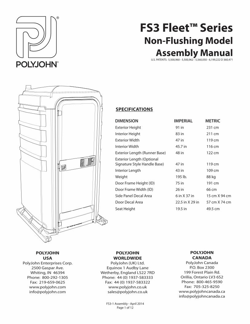
Exterior Height 91 in 231 cm
Interior Height 83 in 211 cm
Exterior Width 47 in 119 cm
Interior Width 45.7 in 116 cm
Exterior Length (Runner Base) 48 in 122 cm
Exterior Length (Optional Signature Style Handle Base) 47 in 119 cm
Interior Length 43 in 109 cm
Weight 195 lb. 88 kg
Door Frame Height (ID) 75 in 191 cm
Door Frame Width (ID) 26 in 66 cm
Side Panel Decal Area 6 in X 37 in 15 cm X 94 cm
Door Decal Area 22.5 in X 29 in 57 cm X 74 cm
Seat Height 19.5 in 49.5 cm
SPECIFICATIONS
DIMENSION IMPERIAL METRIC
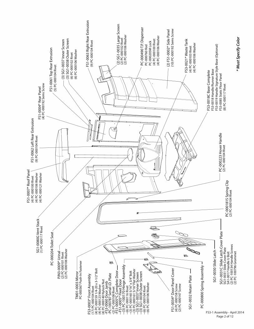
PC-0
0049
0 T.
P. D
ispe
nser
PC-0
0076
0 Ro
dPC
-000
205M
Loc
k(4
) PC-
0001
00 R
ivet
(4
) PC-
0001
06 W
ashe
r
(2) F
S1-0
002*
Sid
e Pa
nel
(10)
PC-
0001
92 S
ems
Scre
w
FS1-
0062
Lef
t Rea
r Ext
rusi
on(9
) PC-
0001
04 R
ivet
FS1-
0061
Top
Rear
Ext
rusi
on(5
) PC-
0001
04 R
ivet
(3) S
G1-
0037
Inne
r Scr
een
(3) S
G1-
0038
Out
er S
cree
n(6
) PC-
0001
02 R
ivet
(6
) PC-
0001
06 W
ashe
r
FS1-
0063
Rig
ht R
ear E
xtru
sion
(9) P
C-00
0104
Riv
et
FS1-
0007
* Ro
of P
anel
(4) P
C-00
0100
Riv
et
(4) P
C-00
0106
Was
her
(4) P
C-00
0121
Was
her
FS3-
0021
* Was
te T
ank
(4) P
C-00
0103
Riv
et
(4) P
C-00
0106
Was
her
FS3-
0018
C Ba
se C
ompl
ete
FS3-
0018
Han
dle/
Runn
er B
ase
FS3-
0019
Han
dle
Sign
atur
e St
yle
Base
(Opt
iona
l)FS
3-00
85 S
tatic
Flo
or P
anel
(8) P
C-00
0117
Riv
et
(2) S
G1-
0035
Lar
ge S
cree
n(2
) PC-
0001
02 R
ivet
(2
) PC-
0001
06 W
ashe
r
PC-0
0020
4 To
ilet S
eat
PJN
3-00
09*
Urin
al(2
) PC-
0001
01 R
ivet
(2
) PC-
0001
06 W
ashe
r
SG1-
0080
G V
ent S
tack
(1) P
C-00
0117
Riv
et
FS3-
0003
* Fr
ont A
ssem
bly
(17)
PC-
0001
04 R
ivet
(4
) PC-
0001
59 1
/4-2
0 x
3-1/
2” B
olt
(4) P
C-00
0123
Was
her
(4) P
C-00
0140
Nyl
ock
Nut
-F
S3-0
060
Doo
r Jam
b-P
C-10
0787
Ser
ial I
.D. P
late
-(2) P
C-00
0108
Riv
et-F
S1-0
005*
C Co
mpl
ete
Doo
r--
FS1-
0005
* Fl
eet D
oor
--(3
) PC-
1001
70 H
inge
Ass
embl
y --
(6) P
C-00
0116
Riv
et
--(3
) PC-
0001
60 5
/16”
x 3
/4” B
olt
--(3
) PC-
0001
61 5
/16”
Fla
t Was
her
--(3
) SG
1-00
37 In
ner S
cree
n--
(3) S
G1-
0038
Out
er S
cree
n--
(6) P
C-00
0104
Riv
et
--(6
) PC-
0001
06 W
ashe
r
TM01
-000
3 M
irror
PC-0
0036
7 Pu
sh-In
Fas
tene
r
SG1-
0032
Ret
ain
Plat
e
FS1-
0034
* D
oor P
anel
Cov
er(4
) PC-
0001
58 S
crew
(2
) PC-
0001
47 S
crew
SG1-
0030
Slid
e La
tch
PC-0
0018
1S S
prin
g Cl
ip(2
) PC-
0001
04 R
ivet
SG1-
0031
C Sl
ide
Latc
h Co
ver P
late
SG1-
0031
Slid
e Co
ver P
late
SA1-
0017
Han
dle
U B
olt
(2) P
C-10
0134
Han
dle
Scre
ws
(2) P
C-10
0796
Gro
mm
et
FS1-
0004
* Re
ar P
anel
(4) P
C-00
0192
Sem
s Sc
rew
PC-0
0022
3 H
over
Han
dle
(2) P
C-00
0104
Riv
et
PC-0
0080
0 Sp
ring
Asse
mbl
y
* M
ust S
peci
fy C
olor
FS3-1 Assembly - April 2014Page 2 of 12
FS3-1 Assembly - April 2014 Page 3 of 12
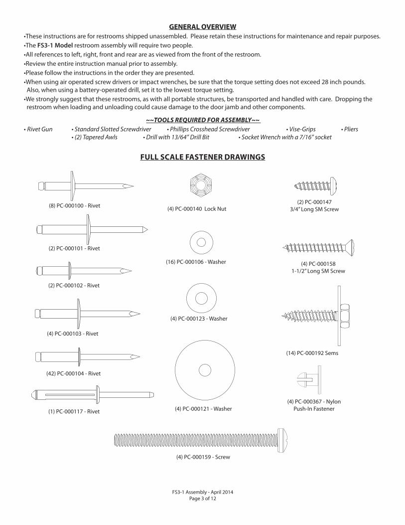
GENERAL OVERVIEW
•These instructions are for restrooms shipped unassembled. Please retain these instructions for maintenance and repair purposes.•The FS3-1 Model restroom assembly will require two people.•All references to left, right, front and rear are as viewed from the front of the restroom.•Review the entire instruction manual prior to assembly.•Please follow the instructions in the order they are presented. •When using air operated screw drivers or impact wrenches, be sure that the torque setting does not exceed 28 inch pounds. Also, when using a battery-operated drill, set it to the lowest torque setting.•We strongly suggest that these restrooms, as with all portable structures, be transported and handled with care. Dropping the restroom when loading and unloading could cause damage to the door jamb and other components.
~~TOOLS REQUIRED FOR ASSEMBLY~~
• Rivet Gun • Standard Slotted Screwdriver • Phillips Crosshead Screwdriver • Vise-Grips • Pliers • (2) Tapered Awls • Drill with 13/64” Drill Bit • Socket Wrench with a 7/16” socket
FULL SCALE FASTENER DRAWINGS
(14) PC-000192 Sems
(4) PC-000140 Lock Nut
(4) PC-000123 - Washer
(4) PC-000121 - Washer(1) PC-000117 - Rivet
(16) PC-000106 - Washer
(42) PC-000104 - Rivet
(8) PC-000100 - Rivet
(2) PC-000101 - Rivet
(4) PC-000367 - NylonPush-In Fastener
(4) PC-000159 - Screw
(4) PC-000103 - Rivet
(2) PC-000102 - Rivet
(4) PC-0001581-1/2” Long SM Screw
(2) PC-0001473/4” Long SM Screw
FS3-1 Assembly - April 2014Page 4 of 12
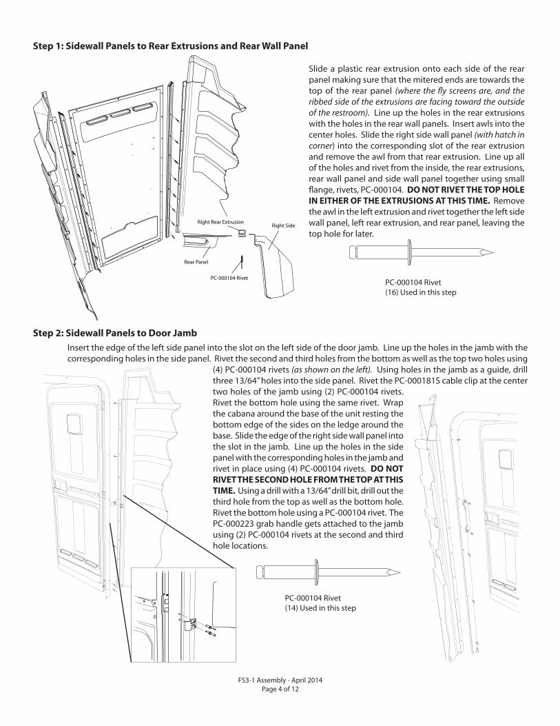
Step 1: Sidewall Panels to Rear Extrusions and Rear Wall Panel
Slide a plastic rear extrusion onto each side of the rear panel making sure that the mitered ends are towards the top of the rear panel (where the fl y screens are, and the ribbed side of the extrusions are facing toward the outside of the restroom). Line up the holes in the rear extrusions with the holes in the rear wall panels. Insert awls into the center holes. Slide the right side wall panel (with hatch in corner) into the corresponding slot of the rear extrusion and remove the awl from that rear extrusion. Line up all of the holes and rivet from the inside, the rear extrusions, rear wall panel and side wall panel together using small fl ange, rivets, PC-000104. DO NOT RIVET THE TOP HOLE
IN EITHER OF THE EXTRUSIONS AT THIS TIME. Remove the awl in the left extrusion and rivet together the left side wall panel, left rear extrusion, and rear panel, leaving the top hole for later.
Right Side
Rear Panel
Right Rear Extrusion
PC-000104 Rivet
Insert the edge of the left side panel into the slot on the left side of the door jamb. Line up the holes in the jamb with the corresponding holes in the side panel. Rivet the second and third holes from the bottom as well as the top two holes using
(4) PC-000104 rivets (as shown on the left). Using holes in the jamb as a guide, drill three 13/64” holes into the side panel. Rivet the PC-000181S cable clip at the center two holes of the jamb using (2) PC-000104 rivets. Rivet the bottom hole using the same rivet. Wrap the cabana around the base of the unit resting the bottom edge of the sides on the ledge around the base. Slide the edge of the right side wall panel into the slot in the jamb. Line up the holes in the side panel with the corresponding holes in the jamb and rivet in place using (4) PC-000104 rivets. DO NOT
RIVET THE SECOND HOLE FROM THE TOP AT THIS
TIME. Using a drill with a 13/64” drill bit, drill out the third hole from the top as well as the bottom hole. Rivet the bottom hole using a PC-000104 rivet. The PC-000223 grab handle gets attached to the jamb using (2) PC-000104 rivets at the second and third hole locations.
Step 2: Sidewall Panels to Door Jamb
PC-000104 Rivet(14) Used in this step
PC-000104 Rivet(16) Used in this step
FS3-1 Assembly - April 2014 Page 5 of 12
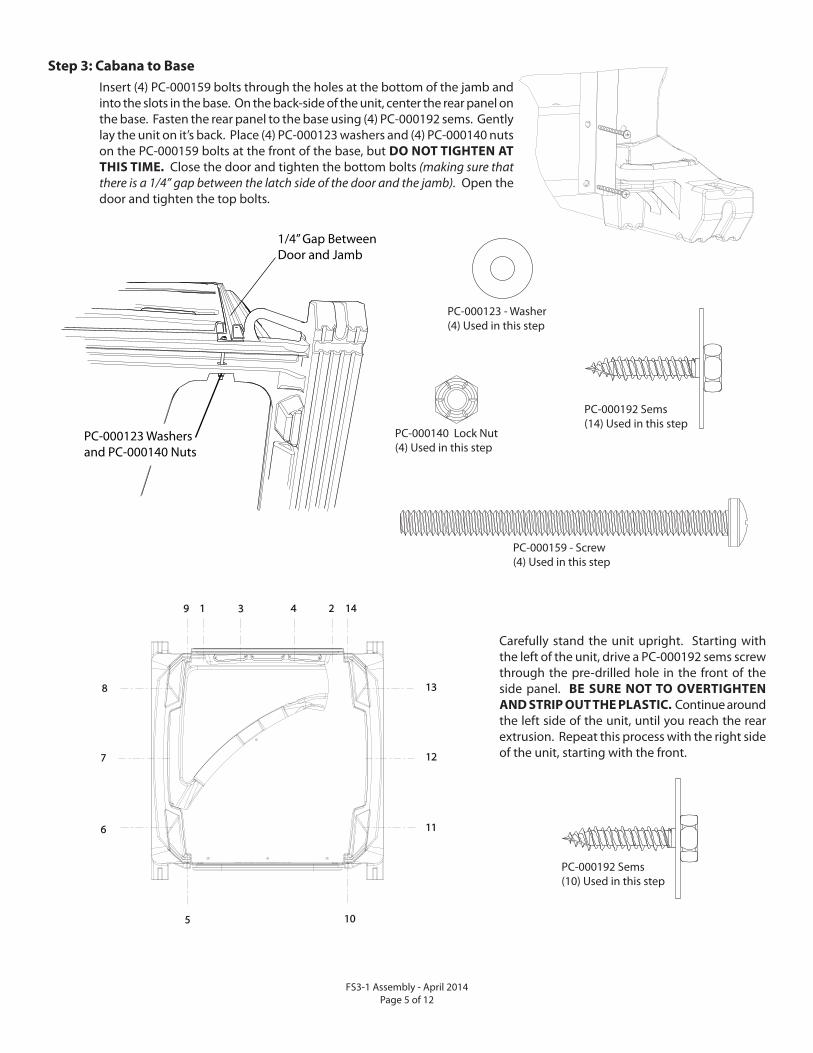
Step 3: Cabana to Base
Insert (4) PC-000159 bolts through the holes at the bottom of the jamb and into the slots in the base. On the back-side of the unit, center the rear panel on the base. Fasten the rear panel to the base using (4) PC-000192 sems. Gently lay the unit on it’s back. Place (4) PC-000123 washers and (4) PC-000140 nuts on the PC-000159 bolts at the front of the base, but DO NOT TIGHTEN AT
THIS TIME. Close the door and tighten the bottom bolts (making sure that there is a 1/4” gap between the latch side of the door and the jamb). Open the door and tighten the top bolts.
PC-000159 - Screw(4) Used in this step
PC-000192 Sems(14) Used in this step
PC-000140 Lock Nut(4) Used in this step
PC-000123 - Washer(4) Used in this step
1/4” Gap BetweenDoor and Jamb
PC-000123 Washersand PC-000140 Nuts
Carefully stand the unit upright. Starting with the left of the unit, drive a PC-000192 sems screw through the pre-drilled hole in the front of the side panel. BE SURE NOT TO OVERTIGHTEN
AND STRIP OUT THE PLASTIC. Continue around the left side of the unit, until you reach the rear extrusion. Repeat this process with the right side of the unit, starting with the front.
9 1 3 4 2
8
7
6
13
12
11
5 10
14
PC-000192 Sems(10) Used in this step
FS3-1 Assembly - April 2014Page 6 of 12
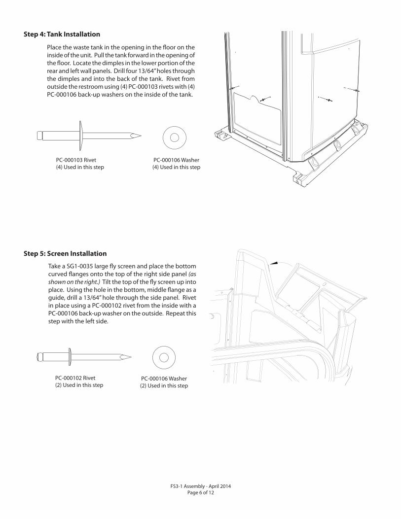
Place the waste tank in the opening in the fl oor on the inside of the unit. Pull the tank forward in the opening of the fl oor. Locate the dimples in the lower portion of the rear and left wall panels. Drill four 13/64” holes through the dimples and into the back of the tank. Rivet from outside the restroom using (4) PC-000103 rivets with (4) PC-000106 back-up washers on the inside of the tank.
PC-000103 Rivet(4) Used in this step
PC-000106 Washer(4) Used in this step
Step 4: Tank Installation
Step 5: Screen Installation
Take a SG1-0035 large fl y screen and place the bottom curved fl anges onto the top of the right side panel (as shown on the right.) Tilt the top of the fl y screen up into place. Using the hole in the bottom, middle fl ange as a guide, drill a 13/64” hole through the side panel. Rivet in place using a PC-000102 rivet from the inside with a PC-000106 back-up washer on the outside. Repeat this step with the left side.
PC-000102 Rivet(2) Used in this step
PC-000106 Washer(2) Used in this step
FS3-1 Assembly - April 2014 Page 7 of 12
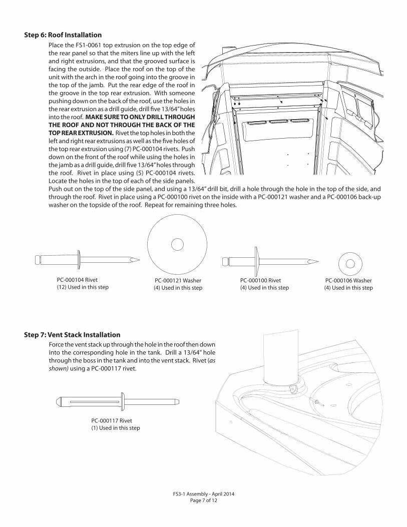
PC-000106 Washer(4) Used in this step
PC-000100 Rivet(4) Used in this step
PC-000121 Washer(4) Used in this step
PC-000104 Rivet(12) Used in this step
Step 6: Roof Installation
Place the FS1-0061 top extrusion on the top edge of the rear panel so that the miters line up with the left and right extrusions, and that the grooved surface is facing the outside. Place the roof on the top of the unit with the arch in the roof going into the groove in the top of the jamb. Put the rear edge of the roof in the groove in the top rear extrusion. With someone pushing down on the back of the roof, use the holes in the rear extrusion as a drill guide, drill fi ve 13/64” holes into the roof. MAKE SURE TO ONLY DRILL THROUGH
THE ROOF AND NOT THROUGH THE BACK OF THE
TOP REAR EXTRUSION. Rivet the top holes in both the left and right rear extrusions as well as the fi ve holes of the top rear extrusion using (7) PC-000104 rivets. Push down on the front of the roof while using the holes in the jamb as a drill guide, drill fi ve 13/64” holes through the roof. Rivet in place using (5) PC-000104 rivets. Locate the holes in the top of each of the side panels. Push out on the top of the side panel, and using a 13/64” drill bit, drill a hole through the hole in the top of the side, and through the roof. Rivet in place using a PC-000100 rivet on the inside with a PC-000121 washer and a PC-000106 back-up washer on the topside of the roof. Repeat for remaining three holes.
Force the vent stack up through the hole in the roof then down into the corresponding hole in the tank. Drill a 13/64” hole through the boss in the tank and into the vent stack. Rivet (as shown) using a PC-000117 rivet.
PC-000117 Rivet(1) Used in this step
Step 7: Vent Stack Installation
FS3-1 Assembly - April 2014Page 8 of 12
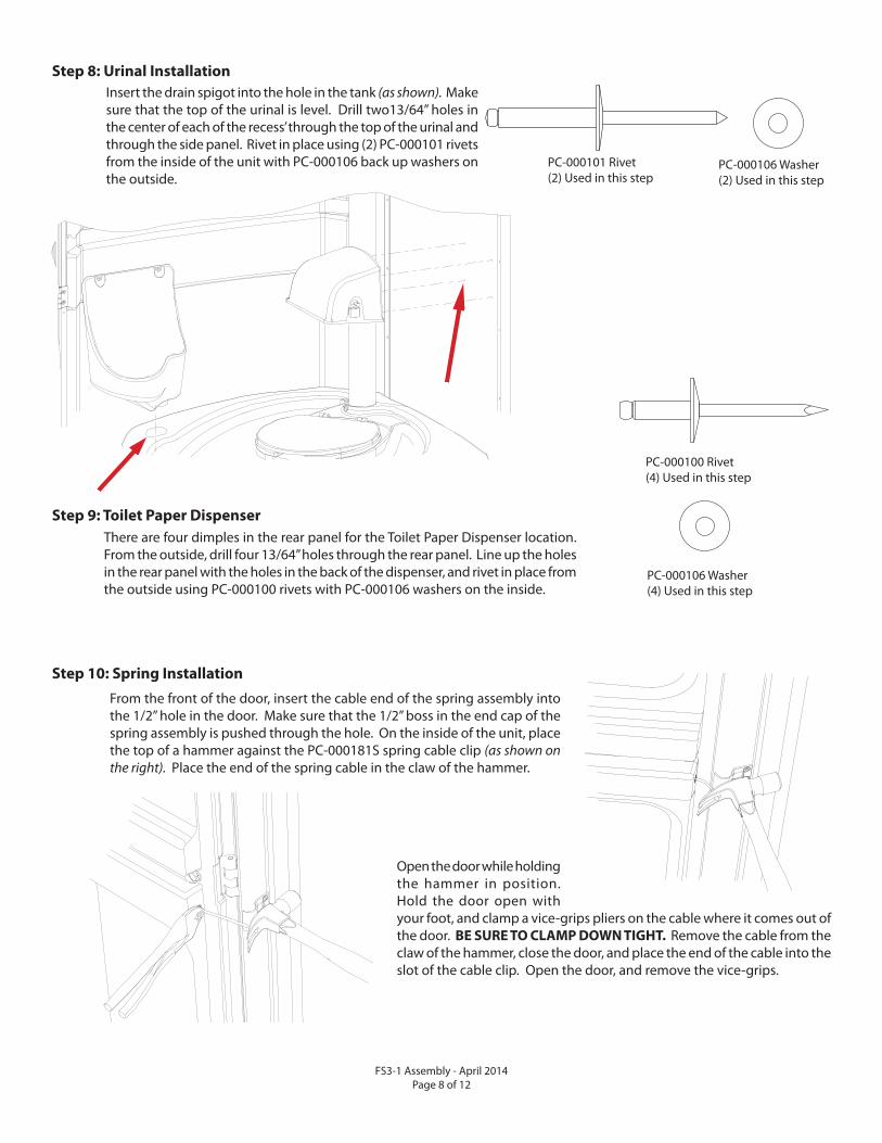
Step 10: Spring Installation
From the front of the door, insert the cable end of the spring assembly into the 1/2” hole in the door. Make sure that the 1/2” boss in the end cap of the spring assembly is pushed through the hole. On the inside of the unit, place the top of a hammer against the PC-000181S spring cable clip (as shown on the right). Place the end of the spring cable in the claw of the hammer.
Open the door while holding the hammer in position. Hold the door open with your foot, and clamp a vice-grips pliers on the cable where it comes out of the door. BE SURE TO CLAMP DOWN TIGHT. Remove the cable from the claw of the hammer, close the door, and place the end of the cable into the slot of the cable clip. Open the door, and remove the vice-grips.
Insert the drain spigot into the hole in the tank (as shown). Make sure that the top of the urinal is level. Drill two13/64” holes in the center of each of the recess’ through the top of the urinal and through the side panel. Rivet in place using (2) PC-000101 rivets from the inside of the unit with PC-000106 back up washers on the outside.
Step 8: Urinal Installation
PC-000101 Rivet(2) Used in this step
PC-000106 Washer(2) Used in this step
There are four dimples in the rear panel for the Toilet Paper Dispenser location. From the outside, drill four 13/64” holes through the rear panel. Line up the holes in the rear panel with the holes in the back of the dispenser, and rivet in place from the outside using PC-000100 rivets with PC-000106 washers on the inside.
Step 9: Toilet Paper Dispenser
PC-000106 Washer(4) Used in this step
PC-000100 Rivet(4) Used in this step
FS3-1 Assembly - April 2014 Page 9 of 12
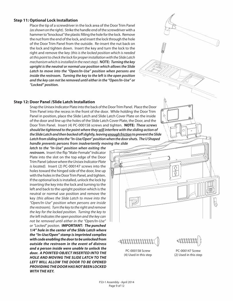
Step 11: Optional Lock Installation
Place the tip of a screwdriver in the lock area of the Door Trim Panel (as shown on the right). Strike the handle end of the screwdriver with a hammer to “knockout” the plastic fi lling the hole for the lock. Remove the nut from the end of the lock, and insert the lock through the hole of the Door Trim Panel from the outside. Re-insert the nut back on the lock and tighten down. Insert the key and turn the lock to the right and remove the key (this is the locked position which is needed at this point to check the lock for proper installation with the Slide Latch mechanism which is installed in the next step). NOTE: Turning the key upright is the neutral or normal use position which allows the Slide Latch to move into the “Open/In-Use” position when persons are inside the restroom. Turning the key to the left is the open position and the key can not be removed until either in the “Open/In-Use” or “Locked” position.
Snap the Unisex Indicator Plate into the back of the Door Trim Panel. Place the Door Trim Panel into the recess in the front of the door. While holding the Door Trim Panel in position, place the Slide Latch and Slide Latch Cover Plate on the inside of the door and line up the holes of the Slide Latch Cover Plate, the Door, and the Door Trim Panel. Insert (4) PC-000158 screws and tighten. NOTE: These screws should be tightened to the point where they will interfere with the sliding action of the Slide Latch and then backed off slightly, leaving enough friction to prevent the Slide Latch from sliding into the “In-Use/Open” position when the door shuts. The U Shaped handle prevents persons from inadvertently moving the slide latch to the “In-Use” position when exiting the restroom. Insert the fl ip “Male-Female” Indicator Plate into the slot on the top edge of the Door Trim Panel (above where the Unisex Indicator Plate is located). Insert (2) PC-000147 screws into the holes toward the hinged side of the door, line up with the holes in the Door Trim Panel, and tighten. If the optional lock is installed, unlock the lock by inserting the key into the lock and turning to the left and back to the upright position which is the neutral or normal use position and remove the key (this allows the Slide Latch to move into the “Open/In-Use” position when persons are inside the restroom). Turn the key to the right and remove the key for the locked position. Turning the key to the left indicates the open position and the key can not be removed until either in the “Open/In-Use” or “Locked” positon. IMPORTANT: The punched
1/4” hole in the center of the Slide Latch where
the “In-Use/Open” stamp is imprinted complies
with code enabling the door to be unlocked from
outside the restroom in the event of distress
and a person inside were unable to unlock the
door. A POINTED OBJECT INSERTED INTO THE
HOLE AND MOVING THE SLIDE LATCH TO THE
LEFT WILL ALLOW THE DOOR TO BE OPENED
PROVIDING THE DOOR HAS NOT BEEN LOCKED
WITH THE KEY.
Step 12: Door Panel /Slide Latch Installation
PC-000158 Screw(4) Used in this step
PC-000147 Screw(2) Used in this step
FS3-1 Assembly - April 2014Page 10 of 12
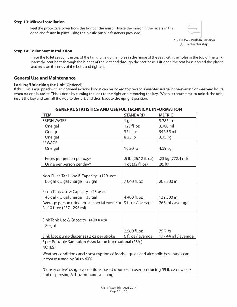
GENERAL STATISTICS AND USEFUL TECHNICAL INFORMATION
ITEM STANDARD METRIC
FRESH WATER 1 gal 3.785 ltr One gal 128 fl . oz 3,780 ml One qt 32 fl . oz 946.35 ml One gal 8.33 lb 3.75 kgSEWAGE One gal 10.20 lb 4.59 kg
Feces per person per day* .5 lb (26.12 fl . oz) .23 kg (772.4 ml) Urine per person per day* 1 qt (32 fl . oz) .95 ltr
Non-Flush Tank Use & Capacity - (120 uses) 60 gal < 5 gal charge = 55 gal 7,040 fl . oz 208,200 ml
Flush Tank Use & Capacity - (75 uses) 40 gal < 5 gal charge = 35 gal 4,480 fl . oz 132,500 mlAverage person urination at special events = 8 - 10 fl . oz (237 - 296 ml)
9 fl . oz / average 266 ml / average
Sink Tank Use & Capacity - (400 uses) 20 gal
Sink foot pump dispenses 2 oz per stroke 2,560 fl . oz6 fl . oz / average
75.7 ltr177.44 ml / average
* per Portable Sanitation Association International (PSAI)NOTES:
Weather conditions and consumption of foods, liquids and alcoholic beverages can increase usage by 30 to 40%.
“Conservative” usage calculations based upon each user producing 59 fl . oz of waste and dispensing 6 fl . oz for hand washing.
General Use and Maintenance
Locking/Unlocking the Unit (Optional)If this unit is equipped with an optional exterior lock, it can be locked to prevent unwanted usage in the evening or weekend hours when no one is onsite. This is done by turning the lock to the right and removing the key. When it comes time to unlock the unit, insert the key and turn all the way to the left, and then back to the upright position.
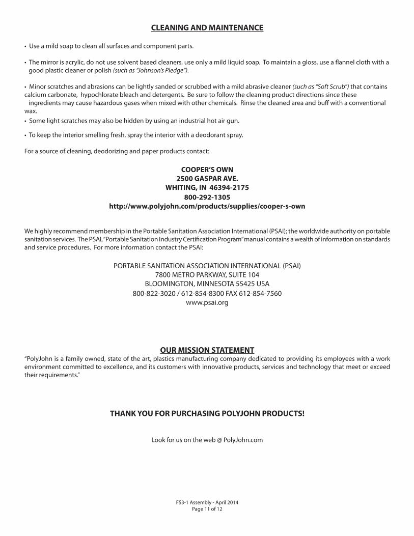
Step 13: Mirror Installation
Peel the protective cover from the front of the mirror. Place the mirror in the recess in the door, and fasten in place using the plastic push in fasteners provided.
PC-000367 - Push-In Fastener(4) Used in this step
Step 14: Toilet Seat Installation
Place the toilet seat on the top of the tank. Line up the holes in the hinge of the seat with the holes in the top of the tank. Insert the seat bolts through the hinges of the seat and through the seat base. Lift open the seat base, thread the plastic seat nuts on the ends of the bolts and tighten.
FS3-1 Assembly - April 2014 Page 11 of 12
We highly recommend membership in the Portable Sanitation Association International (PSAI); the worldwide authority on portable sanitation services. The PSAI, “Portable Sanitation Industry Certifi cation Program” manual contains a wealth of information on standards and service procedures. For more information contact the PSAI:
PORTABLE SANITATION ASSOCIATION INTERNATIONAL (PSAI)7800 METRO PARKWAY, SUITE 104
BLOOMINGTON, MINNESOTA 55425 USA800-822-3020 / 612-854-8300 FAX 612-854-7560
www.psai.org
OUR MISSION STATEMENT“PolyJohn is a family owned, state of the art, plastics manufacturing company dedicated to providing its employees with a work environment committed to excellence, and its customers with innovative products, services and technology that meet or exceed their requirements.”
THANK YOU FOR PURCHASING POLYJOHN PRODUCTS!
Look for us on the web @ PolyJohn.com
CLEANING AND MAINTENANCE
• Use a mild soap to clean all surfaces and component parts.
• The mirror is acrylic, do not use solvent based cleaners, use only a mild liquid soap. To maintain a gloss, use a fl annel cloth with a good plastic cleaner or polish (such as “Johnson’s Pledge”).
• Minor scratches and abrasions can be lightly sanded or scrubbed with a mild abrasive cleaner (such as “Soft Scrub”) that contains calcium carbonate, hypochlorate bleach and detergents. Be sure to follow the cleaning product directions since these ingredients may cause hazardous gases when mixed with other chemicals. Rinse the cleaned area and buff with a conventional wax.• Some light scratches may also be hidden by using an industrial hot air gun.
• To keep the interior smelling fresh, spray the interior with a deodorant spray.
For a source of cleaning, deodorizing and paper products contact:
COOPER’S OWN
2500 GASPAR AVE.
WHITING, IN 46394-2175
800-292-1305
http://www.polyjohn.com/products/supplies/cooper-s-own

FS3-1 Assembly - April 2014 Page 12 of 12


