
FRESHPOINT U440 ULTRAFILTRATION SYSTEMSERVICE MANUAL
waterpurification.pentair.com

TABLE OF CONTENTSINSTALLATION AND START UP CHECKLIST ........................... 3PRODUCT SPECIFICATIONS AND IMPORTANT INFORMATION ............................................ 4IMPORTANT! READ THIS FIRST ............................................... 4SAFETY, CAUTIONS AND WARNINGS ..................................... 5DIMENSIONAL DRAWING ........................................................ 5FLUSHING SCHEDULE ........................................................... 6INSTALLATION INSTRUCTIONS ............................................... 6FRESHPOINT ASSEMBLY......................................................... 13SYSTEM START UP ................................................................... 14MULTI-UNIT FRESHPOINT INSTALLATION ............................. 17BASIC PROGRAMMING QUICK REFERENCE GUIDE ............... 18MASTER RESET ....................................................................... 20SERVICE AND MAINTENANCE ................................................ 21TROUBLESHOOTING ................................................................ 22FLOW RATE VS. DRIVING PRESSURE ...................................... 23APPENDIX A - PERFORMANCE MONITORING ........................ 23SERVICE ASSEMBLIES ............................................................ 23
IMPORTANT PLEASE READ: • The information, specifications and illustrations in this
manual are based on the latest information available at the time of printing. The manufacturer reserves the right to make changes at any time without notice.
• This manual is intended as a guide for service of the controller only. System installation requires information from a number of suppliers not known at the time of manufacture. This product should be installed by a plumbing professional.
• This unit is designed to be installed on potable water systems only.
• This product must be installed in compliance with all state and municipal plumbing and electrical codes. Permits may be required at the time of installation.
• If daytime operating pressure exceeds 80 psi (552 kPa), nighttime pressures may exceed pressure limits. A pressure reducing valve must be installed.
• Do not install the unit where temperatures may drop below 34°F (1°C) or above 110°F (43°C).
• Do not place the unit in direct sunlight. Black units will absorb radiant heat increasing internal temperatures.
• Do not strike the controller or any of the components.• Warranty of this product extends to manufacturing
defects. Misapplication of this product may result in failure to properly condition water, or damage to product.
• A prefilter should be used on installations in which free solids are present.
• Correct and constant voltage must be supplied to the controller to maintain proper function.
CALIFORNIA PROPOSITION 65 WARNINGWARNING: This product contains chemicals known to the
State of California to cause cancer or birth defects or other reproductive harm.
2 • FreshPoint U440
INSTALLATION AND START UP CHECKLIST• Use this form to record initial system hardware, site
conditions, and controller programming information.• Retain a copy for future reference.• Fill in the appropriate data (if available).• Checklist data should be collected and logged on this
form for each system installed.
Start Up DataInstallation Date: ___________________________Installer: _________________________________Installation Site: ___________________________Application: _______________________________System Model/Serial Number: ______________Water Source: ___________________________Pretreatment Installed: ______________________Backflush Kit Installed: Yes ________ No _______Set Flushing Program: ____________ Water Analysis: Turbidity: _____________________________ Total Iron: _____________________________ Chlorine: _____________________________ Water Temperature: _____________________ System Inlet Pressure (if available): ________ System Outlet Pressure: (if available):_______Initial Product Water Flow Rate (with flush tank isolated): ____________________Other Program Details: _______________________________________________________________ General Notes: ______________________________________________________________________________________________________________________________________________________________________________________________________________________________________________________
Checklist of Installation/Start Up Steps
1. Installation location allows access to membrane ___2. Mounting provision accommodates system weight ___3. Listed components/fittings present ___4. Loose components assembled to system ___5. System securely mounted ___6. Solenoid valve/flow meter signal connections ___7. Plumbing connections completed ___8. Initial flush w/o leaks ___9. Electrical power connected ___10. System sanitized ___11. Controller display okay ___12. All programming steps completed ___13. Proper operation verified ___14. Installation/Set Up information entered onto form ___Specific Installation Notes (Problems/Suggestions/Comments): _____________________________________________________________________________________________________________________________________________________________________________________________________________
_________________________________________
FreshPoint U440 • 3

PRODUCT SPECIFICATIONS AND IMPORTANT INFORMATIONIntroduction to the FreshPoint Ultrafiltration SystemThe FreshPoint ultrafiltration system is an advanced Point of Entry (POE) water treatment device designed to improve the water quality in the entire home. It uses ultrafiltration membrane technology to provide a physical barrier to suspended solids, large molecules, most colloids, and microbes down to 0.025 µm in size. The FreshPoint is not designed to remove ions or other elemental forms such as hardness and heavy metals, or small organic molecules such as pesticides.The FreshPoint system should only be installed by a qualified professional. The installation must comply with all local codes and state or provincial laws and regulations.In addition to meeting codes, laws, and regulations, the home owner should understand the care and maintenance of the FreshPoint system. Please read the information found in this service manual.SAFETY NOTICE: Read all safety precautions before installing,
operating, or servicing the FreshPoint.
Product SpecificationsTechnical Data and Specifications
pH Range During Operation 3-10
Free Chlorine Max. 200 mg/L for cleaning, 4 mg/L for service
Maximum Continuous Flow Recommended 1.2 gpm (surface waters) to 3.0 gpm (well water)
Maximum Intermittent Flow 10 gpm
Recommended Operating Pressure
up to 60 psi (413 kPa)
Maximum Operating Pressure 120 psi (827 kPa)
Minimum Operating Temperature
34°F (Do Not Freeze)
Maximum Operating Temperature
104°F
Contaminant Removal Size 150,000 daltons molecular weight cut-off 0.025 µm nominal pore size
Multibore® CapillariesCapillaries per Fiber 7
Outer Diameter 0.17 inch
Inner Diameter 0.04 inch
Material PESM
Molecular Weight Cutoff (MWCO) 100-150 k daltons
Active Membrane Surface 48.50 ft2
IMPORTANT! READ THIS FIRSTRead this service manual thoroughly before first use.
• All plumbing and electrical codes must be complied with when installing this product.
• Only qualified personnel should install this product.• Check the FreshPoint system periodically to ensure
proper operation (i.e. flushing, flow rate, pressure drop, etc)
• Do not allow the FreshPoint system to be exposed to freezing temperatures. Freezing may damage the system.
• Ensure the membrane does not dry out. Opened membranes should be preserved with a 0.1% sodium bisulfite solution.
• The FreshPoint system will continue to operate as a filter during power loss. However, when power returns after an extended outage, the control may need reprogramming.
• Keep this service manual near the FreshPoint system for future reference.
• The FreshPoint system is intended to treat only potable quality water. It is not intended as the permanent primary treatment of water from a source that is contaminated, such as from radon, pesticides, insecticides, sewage, or wastewater.
• Use lubricants (such as silicone) sparingly.
4 • FreshPoint U440

SAFETY, CAUTIONS AND WARNINGSSafety
• The FreshPoint system must be wired according to local electrical codes to prevent the possibility of electrical shock.
• Do not modify the power supply cord.• The FreshPoint system must be installed in compliance
with local plumbing codes and any other applicable codes. • The FreshPoint system has been designed and tested
to offer reliable service when installed by a qualified professional and operated and maintained according to the instructions in this service manual.
• For safety reasons, the FreshPoint system is furnished with a low voltage power supply to plug into the electrical outlet. Do not replace this power supply with another power supply (except as supplied by the manufacturer).
• Install the FreshPoint system only for its intended use as described in this service manual.
• Do not use corrosive chemicals in the FreshPoint system.• Do not install the FreshPoint system if it has a damaged
cord or plug, if it is not working properly, or if it has been damaged or dropped.
• Do not immerse the cord or plug in water.• Keep the cord away from heated surfaces.• Disconnect the FreshPoint system from the power source
before performing any service or maintenance on the solenoid valves.
• Do not plug in the controller power supply if there is water on the electrical wiring or the power supply.
• Always shut off the water flow and release water pressure before cleaning or maintaining the FreshPoint system.
• The FreshPoint system is intended for indoor use only. The power supply and controller must not be exposed to weather elements.
• The outlet used for power to the FreshPoint system should be an unswitched outlet.
• This appliance is not intended for use by persons (including children) with reduced physical, sensory, or mental capabilities, or lack of experience and knowledge, unless thye have been given supervision or instruction concerning use of the appliance by a person responsible for their safety.
• Children shall not play with the appliance.• Cleaning shall not be made by children without
supervision.NOTE: This product should be installed by a qualified
professional. Comply with all plumbing and electrical codes when installing this product.
CAUTION Minimum water pressure 20 psi (138 kPa). Maximum water pressure 120 psi (827 kPa).
CAUTION Minimum water temperature 3°F (1°C). Maximum water temperature 104°F (40°C).
CAUTION Ambient temperature 34°F to 104°F (1°C to 40°C).CAUTION Disconnect all power sources before servicing.CAUTION Always operate the controller with the cover in
place.WARNING: The system MUST be depressurized before
removing any connections for servicing.
DIMENSIONAL DRAWING
220.038.663
441.6417.388
534.8621.058
X2 187.967.400
209.098.232
1359.7753.534
268.0310.552
Figure 1 Dimensional Drawing for the FreshPoint Ultrafiltration System
FreshPoint U440 • 5

FLUSHING SCHEDULE Flushing ScheduleThe FreshPoint system is flushed on a schedule dependent on the quality of water being treated.
Default Factory SettingsFlush Frequency: 100 gallons (378 L)Flush Duration: 0.5 minutesDay Override: 1 day
These settings may need to be adjusted based on the analysis for the water treated and practical experience with fouling. The FreshPoint system will automatically initiate a flush if 24 hours (for each 1 day of the Day Override setting) has elapsed since the last flow initiated flush. This setting is adjusted in the day override setting in master programming. A post-ultrafilter pressure tank is recommended to ensure sufficient flow and pressure to the home during a flush cycle. The backflush surge tank (where installed) will perform the same function.Refer to the table below for initial set up.
Water Source Typical Water Quality to Filter
(with recommended pretreatment)
Recommended Pretreatment1
Backflush Kit Scheduled Flush and Duration
Surface Water (Municipally Treated)
• Chlorine < 4.0 mg/l• Turbidity < 5.0 NTU• TOC < 2.0 mg/L• SDI15 < 6.67• Metals (Fe, Mn, Cu,
etc.) < 1 mg/l
• 200 micron prefilter
Recommended Every 100 gal (378 L) for 30 sec.
Surface Water (Private Multi Barrier Treatment)
• Chlorine > 2mg/l, < 4.0 mg/l
• Turbidity < 5.0 NTU• TOC < 10.0 mg/L• SDI15 < 20• Metals (Fe, Mn, Cu,
etc.) < 1 mg/l
• In-Line coagulation and filtration with multimedia filter
• Disinfection with chlorine
• 200 micron prefilter
Recommended Every 50 gal (189 L) for 60 sec.
Well (Municipally Treated)2
• Chlorine < 4.0 mg/l• Turbidity < 5.0 NTU• TOC < 2.0 mg/L• SDI15 < 6.67• Metals (Fe, Mn, Cu,
etc.) < 1 mg/l
• Iron removal filtration (if iron over 1 mg/l)
• 200 micron prefilter
Recommended with high turbidity, suspended solids, colloids, or ferric iron
Every 200 gal (757 L) for 30 sec.
Well (Private)2 • Chlorine < 4.0 mg/l• Turbidity < 1.0 NTU• TOC < 2.0 mg/L• SDI15 < 6.67• Metals (Fe, Mn, Cu,
etc.) < 1 mg/l
• Iron removal filtration(if iron over 1 mg/l)
• Disinfection – optional
• 200 micron prefilter
Recommended with high turbidity, suspended solids, colloids, or ferric iron
Every 100 gal (378 L) for 30 sec.
1 In all cases, a disposable pre-filter cartridge is recommended to protect the FreshPoint system from large particles, plumbing debris, etc. 2 Some shallow wells may have serious contamination problems, hazy water, high TOC, color and high bacterial loads. The backflush kit is recommended to avoid fouling in these installations.NOTE: It is important to understand the water quality and
fouling potential to determine the type of flushing required when installing the FreshPoint system.
Flow Capacity• Assess the household water use, especially peak water
draw. The standard single-element FreshPoint system is sized for 10 gpm (37.8 Lpm) peak capacity flow. Water draw in the house that exceeds peak capacity will have the effect of reduced pressure and volume delivery at the open taps.
• Maximum recommended continuous flow for the FreshPoint system is 1.2 gpm (4.5 Lpm) for surface water, and 3.0 gpm (11 Lpm) for well water.
INSTALLATION INSTRUCTIONSPlumbing
• The system and installation piping should be cleaned before the system is started so that no impurities, abrasive materials, or oily materials are washed into the membranes. The piping must be purged of air to prevent water hammer which can damage the system.
• A bypass system is strongly recommended to permit the most efficient service of the FreshPoint system over its life. Additionally, some local plumbing codes may require a bypass.
• The connections to the FreshPoint housing ports on the system are ½” NPT connections for outlet and drain and ¾" NPT connection for inlet.
• A 10 gpm (37.8 Lpm) flow control is included to be installed on the inlet of the FreshPoint system to ensure the membrane operates in an efficient manner.
• A 7 gpm (26.5 Lpm) flow control is included to be installed on the drain line to maximize water efficiency and ensure proper flushing rates are achieved. Ensure the drain selected has the capacity for this flow rate.
• Private wells often have higher levels of turbidity or suspended solids that can shorten membrane life without adequate flushing. If fouling potential is high, a backflush kit should be installed. The installation of a pressure tank and solenoid valve switches the system from forward flushing to backflushing, thereby extending the membrane life in high fouling potential waters.
• For standard installations, a post-ultrafilter pressure tank is recommended to maintain pressure during a flush cycle.
• The system must be protected from possible back contamination by the installation of an air gap between the FreshPoint drain connection and the drain line.
Electrical RequirementsThe FreshPoint controller requires a constant electrical supply to flush correctly (120 or 220VAC). The system controller and solenoid valve(s) operate on 24 VDC.
PretreatmentPretreatment of the FreshPoint system with a 200 µm filter is recommended. Some installations may require additional pretreatment. Reference the Flushing Schedule (Table 1) or the FreshPoint Ultrafiltration Systems Applications Guide for more information.
FreshPoint Location• Note the location of the water supply and drain when
choosing a mounting location. The FreshPoint system is a point-of-entry (POE) device designed to treat water distributed throughout the entire plumbing system. The installation should be located near the point of entry, but ahead of where plumbing splits for distribution.
6 • FreshPoint U440

• The system mounting bracket has been designed to mount the FreshPoint system sufficiently off the wall to accommodate installation of a pre/post filter inline with the water inlet and/or water outlet of the system.
• Remember to allow for visual and physical access to the meter/programming controls.
• Do not mount the FreshPoint system above any electrical equipment, or above items that may become damaged if they get wet.
• Install the FreshPoint in a location that will allow for easy service access. Service and maintenance requires access to the unit and removal and replacement of the membrane element.
• Mount the FreshPoint system to a wall in a vertical orientation using appropriate mounting hardware (not included) capable of supporting 51 pounds (23.1 kilograms).
• The FreshPoint system's footprint is 12” x 12” (30 x 30 cm), exclusive of plumbing connections. The FreshPoint system requires 85” (2.1 m) of vertical room to allow for removal of the membrane, unless plumbing accommodations are made (e.g.: unions). See Figure 1 for a typical installation with dimensions.
• The backflush surge tank, in the backflush kit, requires an additional 16” x 16” (41 x 41 cm) of level floor space.
Plumbing OptionsThere are two options for plumbing in the FreshPoint system:1. Backflush Surge Tank Installation2. Installation (Forward Flush)
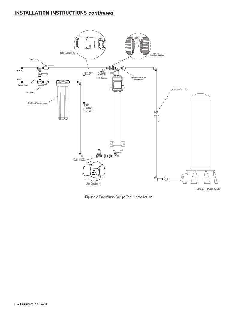
Backflush Surge Tank InstallationInstallations with high fouling potential will require plumbing in a pressurized surge tank and inlet solenoid valve (See Flushing Schedule Table 1). In the backflush mode, the filtered water from a pressure tank flows backward through the membrane from the filtrate side during the flushing cycle. This removes the foulant from the membrane surface as well as material that may have entered into the porous structure. Connect the FreshPoint system to the plumbing supply as shown in Figure 2 Backflush Surge Tank Installation. It is recommended that the plumbing include a system bypass for future servicing, etc. A 200 µm sediment pre-filter is recommended. For ease of membrane element replacement, unions are recommended as indicated on Figure 2 Backflush Surge Tank Installation. The backflush tank should be installed on a tee before the flow meter. The backflush tank precharge pressure should be set to 20 psi (1.3 bar / 138 kPa).NOTE: Installation of the backflush tank after the meter will
cause reverse flow through the meter and could have a detrimental effect on meter performance.
NOTE: Consider that in a typical residential installation that there is a considerable time frame in which the service flow rate is far below the maximum delivery capability of the FreshPoint unit. Therefore, the surge tank will be permitted to store a sufficient quantity of water to satisfy subsequent flushing and service requirements. Alternatively, if the service requirement is continuous and demanding all that the FreshPoint unit is delivering, the surge tank will be unable to store water for subsequent flushing or service. In this case extra measures must be taken to provide flow restrictions or service line closures to permit surge tank filling.
INSTALLATION INSTRUCTIONS continued
FreshPoint U440 • 7
lortnoCwolFtelnI)noitceridwolfetoN(
telnIhsulfkcaB"4/3evlaVffO-tuhS
reteMwolF)noitceridwolfetoN(
lortnoCwolFniarD)noitceridwolfetoN(
evlaVnoitalosIknaT
tsumgnipiPedulcni
tnailpmoc-edocpagria
niarD
telnI
teltuO
evlaVteltuO
evlaVtelnI
evlaVssapyB
)dednemmoceR(retliF-erP
evlaVffO-tuhS1/2” Drain 3/4” NPT Threaded Union
(not supplied)
Figure 2 Backflush Surge Tank Installation
INSTALLATION INSTRUCTIONS continued
61504-U440-BF Rev B
8 • FreshPoint U440

Installation (Forward Flush)This installation approach cleans the membrane periodically by opening the drain valve and allowing the feed stream to remove the suspended solids that have been retained in the fiber lumens and flushed to drain.Connect the FreshPoint system to the household plumbing supply as shown in Figure 3 Tankless Installation. It is recommended that the plumbing include a system bypass for future service. A 200 µm sediment pre-filter is recommended. For ease of membrane element replacement, unions are recommended as indicated on Figure 3 Tankless Installation.NOTE: Installations without a pressure tank may experience
drops in pressure/flow to the home during a flush cycle.
lortnoCwolFtelnI)noitceridwolfetoN(
telnIhsulfkcaB"4/3evlaVffO-tuhS
reteMwolF)noitceridwolfetoN(
lortnoCwolFniarD)noitceridwolfetoN(
tsumgnipiPedulcni
tnailpmoc-edocpagria
niarD
telnI
teltuO
evlaVteltuO
evlaVtelnI
evlaVssapyB
)dednemmoceR(retliF-erP
evlaVffO-tuhS1/2” Drain
INSTALLATION INSTRUCTIONS continued
Figure 3 Tankless Installation
61504-U440-FF Rev B
FreshPoint U440 • 9
Additional Water Treatment Devices• When multiple devices for water treatment equipment
are involved the most effective order of installation must be determined for the specific water source and the treatment objective. This can best be accomplished by a local water treatment professional.
• The FreshPoint system is designed to remove particles much smaller than conventional filtration devices. The FreshPoint system is not designed to be used as a “roughing" filter and, as such, should be installed after conventional filters (iron filters, multimedia filters, etc.) which are used to remove larger suspended solids. This will permit the smallest particles which pass through a conventional filter to be removed by the FreshPoint system without fouling the FreshPoint membrane.
• The small particle removal and turbidity reduction achieved by the FreshPoint system can be beneficial to achieving maximum performance from devices that are installed after the ultrafilter.
• Ferrous (dissolved) iron is not removed by the FreshPoint. Ferric (precipitated) iron is removed by the FreshPoint system. Note that ferric iron may foul the membrane if present at greater than 1 ppm. We recommend that the FreshPoint system be installed after an iron filter or conditioner when iron is present.
• The presence of a low level of chlorine in the supply water will help prevent biofouling of the FreshPoint system, but continuous exposure to more than 4 ppm of chlorine may shorten the life of the membrane. The membrane must not be exposed to ozone. Exposing the membrane to ozone voids the membrane warranty.
FreshPoint Installation InstructionsTools and Supplies Needed:1. Plumber tape or paste for leak free assembly of the pipe
thread connections.CAUTION Ensure that the paste is compatible with PVC
fittings.2. Lubricant for seals (a packet of silicone is supplied)
NOTE: Silicone should be applied sparingly to avoid fouling the membrane.
3. Four ¼" bolts to mount the system to the wall.4. ½" open end wrench to tighten saddle clamp.5. 7/16" open end wrench to tighten ¼” wall mount bolts.6. Crescent wrench that can open to 1-1/2” to grip flow
control.
Unpacking (Refer to "FRESHPOINT ASSEMBLY", pg. 13)1. Open the box with the hardware and verify that all of the
components pictured on the FreshPoint Assembly (pg. 13) are present and undamaged.
2. Open the Plumbing Kit bags and verify that all of the components listed on the parts lists (found in the plumbing kit bags) are present and undamaged.
3. The membrane is packed in a preservative solution, and should not be opened until it is to be installed in the housing.
Hardware Assembly:1. Assembly is most easily done on a horizontal surface.2. Position a mounting bracket (Item 4 of "FRESHPOINT
ASSEMBLY", pg. 13), a saddle (Item 5), and a saddle clamp (Item 5) about 10” from the top of the vessel (Item 1). Leave the bolts loose. Note: The smaller diameter portion of the mounting bolt holes in the mounting bracket must be positioned toward the top of the vessel.
3. Position the bracket of the control (Item 6) between the mounting bracket and the saddle clamp. Ensure control is oriented correctly.
4. Install the remaining mounting bracket, saddle, and saddle clamp at a convenient location near the bottom of the vessel, and tighten the saddle clamp bolts with a ½" wrench.
Vessel Head Removal:1. Remove the top and bottom end caps (Item 1B), and bag of
parts (U-pins and O-rings) from the vessel (Item 1A). Note that the top and bottom end caps are identical.
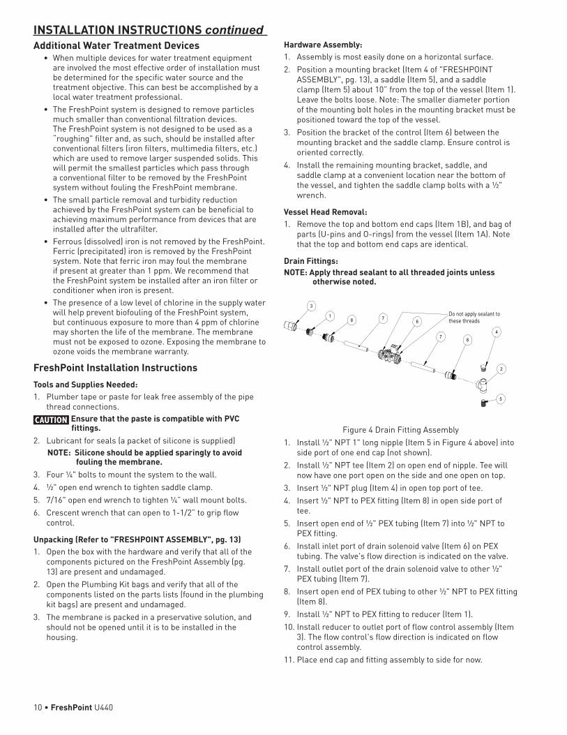
Drain Fittings:NOTE: Apply thread sealant to all threaded joints unless
otherwise noted.
Figure 4
3
18 7
6
7 8
4
2
5
Do not apply sealant to these threads
Drain Fitting Assembly1. Install ½" NPT 1" long nipple (Item 5 in Figure 4 above) into
side port of one end cap (not shown).2. Install ½" NPT tee (Item 2) on open end of nipple. Tee will
now have one port open on the side and one open on top.3. Insert ½" NPT plug (Item 4) in open top port of tee.4. Insert ½" NPT to PEX fitting (Item 8) in open side port of
tee.5. Insert open end of ½" PEX tubing (Item 7) into ½" NPT to
PEX fitting.6. Install inlet port of drain solenoid valve (Item 6) on PEX
tubing. The valve's flow direction is indicated on the valve.7. Install outlet port of the drain solenoid valve to other ½"
PEX tubing (Item 7).8. Insert open end of PEX tubing to other ½" NPT to PEX fitting
(Item 8).9. Install ½" NPT to PEX fitting to reducer (Item 1).10. Install reducer to outlet port of flow control assembly (Item
3). The flow control's flow direction is indicated on flow control assembly.
11. Place end cap and fitting assembly to side for now.
INSTALLATION INSTRUCTIONS continued
10 • FreshPoint U440
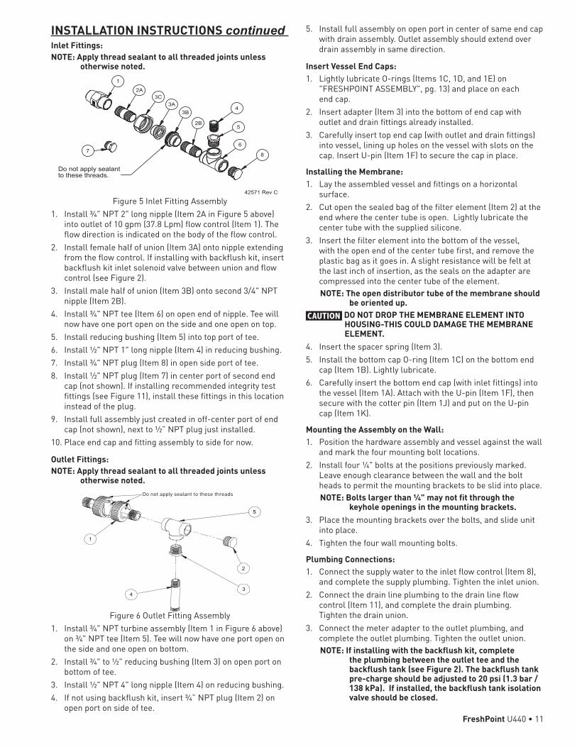
Inlet Fittings:NOTE: Apply thread sealant to all threaded joints unless
otherwise noted.
Figure 5
Do not apply sealantto these threads.
1
2A3C
3A3B
2B
4
5
6
87
42571 Rev C
Inlet Fitting Assembly1. Install ¾" NPT 2" long nipple (Item 2A in Figure 5 above)
into outlet of 10 gpm (37.8 Lpm) flow control (Item 1). The flow direction is indicated on the body of the flow control.
2. Install female half of union (Item 3A) onto nipple extending from the flow control. If installing with backflush kit, insert backflush kit inlet solenoid valve between union and flow control (see Figure 2).
3. Install male half of union (Item 3B) onto second 3/4" NPT nipple (Item 2B).
4. Install ¾" NPT tee (Item 6) on open end of nipple. Tee will now have one port open on the side and one open on top.
5. Install reducing bushing (Item 5) into top port of tee.6. Install ½" NPT 1" long nipple (Item 4) in reducing bushing.7. Install ¾" NPT plug (Item 8) in open side port of tee.8. Install ½" NPT plug (Item 7) in center port of second end
cap (not shown). If installing recommended integrity test fittings (see Figure 11), install these fittings in this location instead of the plug.
9. Install full assembly just created in off-center port of end cap (not shown), next to ½” NPT plug just installed.
10. Place end cap and fitting assembly to side for now.
Outlet Fittings:NOTE: Apply thread sealant to all threaded joints unless
otherwise noted.
Figure 6
1
2
34
5
Do not apply sealant to these threads
Outlet Fitting Assembly1. Install ¾" NPT turbine assembly (Item 1 in Figure 6 above)
on ¾" NPT tee (Item 5). Tee will now have one port open on the side and one open on bottom.
2. Install ¾" to ½" reducing bushing (Item 3) on open port on bottom of tee.
3. Install ½" NPT 4" long nipple (Item 4) on reducing bushing.4. If not using backflush kit, insert ¾” NPT plug (Item 2) on
open port on side of tee.
INSTALLATION INSTRUCTIONS continued 5. Install full assembly on open port in center of same end cap with drain assembly. Outlet assembly should extend over drain assembly in same direction.
Insert Vessel End Caps:1. Lightly lubricate O-rings (Items 1C, 1D, and 1E) on
"FRESHPOINT ASSEMBLY", pg. 13) and place on each end cap.
2. Insert adapter (Item 3) into the bottom of end cap with outlet and drain fittings already installed.
3. Carefully insert top end cap (with outlet and drain fittings) into vessel, lining up holes on the vessel with slots on the cap. Insert U-pin (Item 1F) to secure the cap in place.
Installing the Membrane:1. Lay the assembled vessel and fittings on a horizontal
surface.2. Cut open the sealed bag of the filter element (Item 2) at the
end where the center tube is open. Lightly lubricate the center tube with the supplied silicone.
3. Insert the filter element into the bottom of the vessel, with the open end of the center tube first, and remove the plastic bag as it goes in. A slight resistance will be felt at the last inch of insertion, as the seals on the adapter are compressed into the center tube of the element. NOTE: The open distributor tube of the membrane should
be oriented up. CAUTION DO NOT DROP THE MEMBRANE ELEMENT INTO
HOUSING-THIS COULD DAMAGE THE MEMBRANE ELEMENT.
4. Insert the spacer spring (Item 3).5. Install the bottom cap O-ring (Item 1C) on the bottom end
cap (Item 1B). Lightly lubricate. 6. Carefully insert the bottom end cap (with inlet fittings) into
the vessel (Item 1A). Attach with the U-pin (Item 1F), then secure with the cotter pin (Item 1J) and put on the U-pin cap (Item 1K).
Mounting the Assembly on the Wall:1. Position the hardware assembly and vessel against the wall
and mark the four mounting bolt locations.2. Install four ¼" bolts at the positions previously marked.
Leave enough clearance between the wall and the bolt heads to permit the mounting brackets to be slid into place.NOTE: Bolts larger than ¼" may not fit through the
keyhole openings in the mounting brackets.3. Place the mounting brackets over the bolts, and slide unit
into place.4. Tighten the four wall mounting bolts.
Plumbing Connections:1. Connect the supply water to the inlet flow control (Item 8),
and complete the supply plumbing. Tighten the inlet union.2. Connect the drain line plumbing to the drain line flow
control (Item 11), and complete the drain plumbing. Tighten the drain union.
3. Connect the meter adapter to the outlet plumbing, and complete the outlet plumbing. Tighten the outlet union.NOTE: If installing with the backflush kit, complete
the plumbing between the outlet tee and the backflush tank (see Figure 2). The backflush tank pre-charge should be adjusted to 20 psi (1.3 bar / 138 kPa). If installed, the backflush tank isolation valve should be closed.
FreshPoint U440 • 11

Solenoid Electrical Connection (Refer to Figure 7 Solenoid Electrical Connection Diagram )1. Connect the drain solenoid wire harness to the solenoid
valve.2. If installing with the backflush kit:
A. Install inlet solenoid’s wiring harness (backflush kit) to the control board terminal block. Connect the other end of the wire harness to the inlet solenoid valve.
5
3
6
2
4
1
1 B T
Drain Green
Blue
BlackBlack
Blue
Green
Inlet
Outlet
Figure 7 Solenoid Electrical Connection Diagram
Meter Connection (Refer to Figure 8 Circuit Board Diagram)1. Insert the flow meter cable into the socket on the flow
meter.2. Connect other end of flow meter cable to circuit board in
location shown.
RS-485-1
RS-485-2
Meter
To Solenoid Terminal Block
RSS
Figure 8 Circuit Board Diagram3. Plug the power supply into a 120V or 220V GFI outlet.
INSTALLATION INSTRUCTIONS continuedRemote Flush Connection (Multi-Unit System Kit P/N 4002815 Required)1. Cut one end of Multi-Unit wire harness included in
Multi-Unit System Kit, exposing two bare wires.2. Plug other end of wire harness into port labeled
"RSS" on back of control circuit board. Disassembly of controller casing may be required to access port.
3. Thread wire harness through controller assembly backplate and secure with supplied bushing.
4. Connect differential pressure switch or other remote switch to loose wires and secure. No power is to be supplied into switch.
5. When there is continuous contact closure between the loose wires for the specified interval (1-999 seconds, default 60 seconds; see "Master Programming" on page 19) as supplied by differential pressure switch or other remote switch, a backflush will be started.
12 • FreshPoint U440
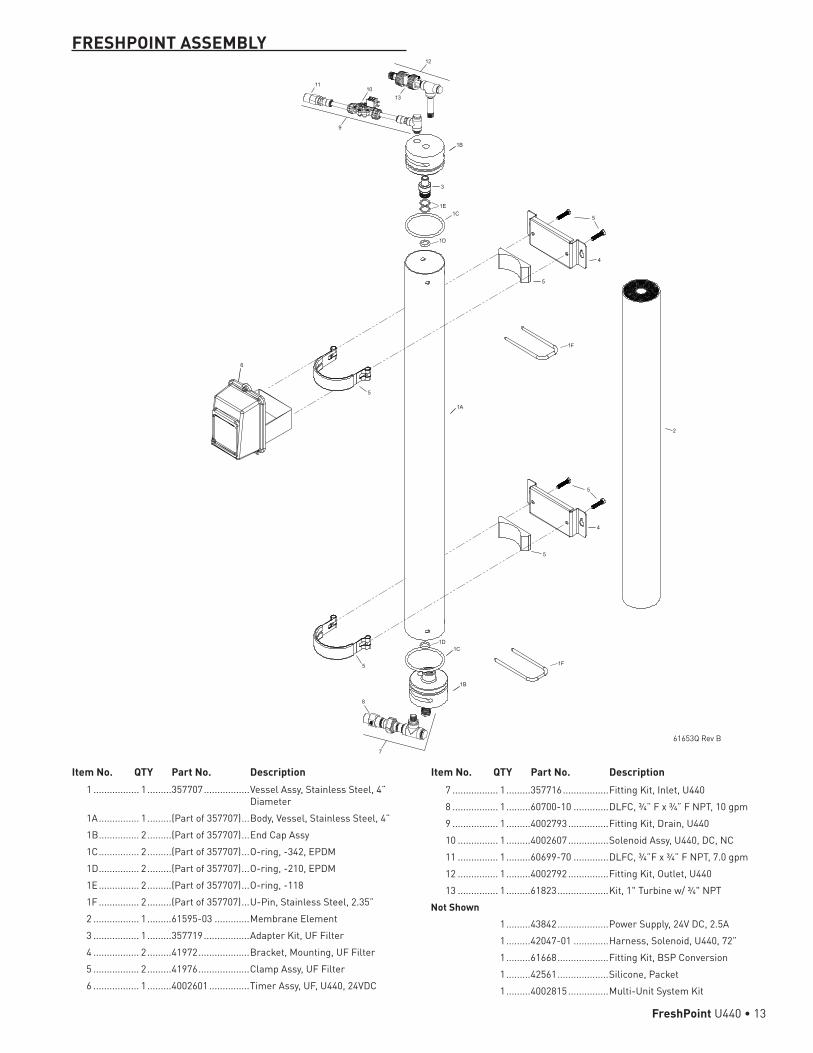
Item No. QTY Part No. Description 1 ................. 1 .........357707 .................Vessel Assy, Stainless Steel, 4”
Diameter 1A ............... 1 .........(Part of 357707) ...Body, Vessel, Stainless Steel, 4” 1B ............... 2 .........(Part of 357707) ...End Cap Assy 1C ............... 2 .........(Part of 357707) ...O-ring, -342, EPDM 1D ............... 2 .........(Part of 357707) ...O-ring, -210, EPDM 1E ............... 2 .........(Part of 357707) ...O-ring, -118 1F ............... 2 .........(Part of 357707) ...U-Pin, Stainless Steel, 2.35” 2 ................. 1 .........61595-03 .............Membrane Element 3 ................. 1 .........357719 .................Adapter Kit, UF Filter 4 ................. 2 .........41972 ...................Bracket, Mounting, UF Filter 5 ................. 2 .........41976 ...................Clamp Assy, UF Filter 6 ................. 1 .........4002601 ...............Timer Assy, UF, U440, 24VDC
7 ................. 1 .........357716 .................Fitting Kit, Inlet, U440 8 ................. 1 .........60700-10 .............DLFC, ¾” F x ¾” F NPT, 10 gpm 9 ................. 1 .........4002793 ...............Fitting Kit, Drain, U440 10 ............... 1 .........4002607 ...............Solenoid Assy, U440, DC, NC 11 ............... 1 .........60699-70 .............DLFC, ¾”F x ¾” F NPT, 7.0 gpm 12 ............... 1 .........4002792 ...............Fitting Kit, Outlet, U440 13 ............... 1 .........61823 ...................Kit, 1" Turbine w/ ¾" NPTNot Shown 1 .........43842 ...................Power Supply, 24V DC, 2.5A 1 .........42047-01 .............Harness, Solenoid, U440, 72” 1 .........61668 ...................Fitting Kit, BSP Conversion 1 .........42561 ...................Silicone, Packet 1 .........4002815 ...............Multi-Unit System Kit
Item No. QTY Part No. Description
FRESHPOINT ASSEMBLY
2
3
13
12
1110
9
6
4
4
5
5
5
5
5
5
1A
1B
1B
1C
1C
1D
1E
1D
1F
1F
8
7
61653Q Rev B
FreshPoint U440 • 13
SYSTEM START UPElectricalFollow the instructions in the programming section of this service manual to set up the control.
Check the FreshPoint System For Leaks• Ensure that all new plumbing connections, the three ports
from the housing, and the two end cap perimeters have no leaks. Correct if needed.
• Manually initiate a flush cycle by pressing and holding the Extra Cycle button for five seconds. Ensure the drain solenoid valve opens and a robust flow goes to the drain, and that the drain can handle the flow.
FlushingFlush the membranes prior to placing the system in service to remove the membrane storage solution.NOTE: If installed, the backflush surge tank isolation valve
should be closed. If there is a tank and no isolation valve, ensure that each flush cycle fills and empties the backflush tank.
NOTE: If installed with the backflush kit, the inlet solenoid valve should not be connected to the wiring harness for flushing at this time, as it will not permit supply water to enter the FreshPoint system. Connect the inlet solenoid after the backflush tank fills with water.
Rinse the preservative solution from the membrane as follows:1. Close the bypass valve of the bypass plumbing
arrangement.2. Open the outlet valve of the bypass plumbing arrangement.3. Slowly open the inlet valve of the bypass plumbing
arrangement. This will fill the module with water without creating a water hammer effect.
4. To expel air from the feed side of the membrane, manually initiate a flushing by pressing and holding the Extra Cycle button on the control for five seconds.
Rinse Cycle 1: 1. Open the service water faucet closest to the FreshPoint
system installation to permit a flow of up to 5 gpm (19 Lpm). Allow the system to flow for twenty minutes.
2. Manually initiate a flush to drain by pressing and holding the Extra Cycle button on the control for five seconds.
3. If a backflush tank is installed and not isolated, ensure that it is emptied by initiating a sufficiently long flush by allowing the control to complete the manual flush cycle.
Rinse Cycle 2:1. Allow the service water to continue to flow at up to 5 gpm
(19 Lpm). Permit the system to flush for an additional twenty minutes.
2. Manually initiate a flush to drain by pressing and holding the Extra Cycle button on the control for five seconds.
3. If a backflush tank is installed and not isolated, ensure that it is emptied by initiating a sufficiently long flush by allowing the control to complete the manual flush cycle.
Rinse Cycle 3:1. Allow the service water to continue to flow at up to 5 gpm
(19 Lpm). Permit the system to flow for an additional twenty minutes.
2. Manually initiate a flush to drain by pressing and holding the Extra Cycle button on the control for five seconds.
3. If a flush tank is installed, ensure that it is emptied by initiating a sufficiently long flush by allowing the control to complete the manual flush cycle.
4. While the system is flushing check all plumbing connections for any possible leaks.
System Sanitizing - With Prefilter InstalledThe unit should be sanitized/disinfected after the initial start up rinsing procedure, or in the case of biological fouling. The system should be disinfected after flushing but prior to use. Disinfect after the integrity test, if performed.CAUTION Sodium hypochlorite (bleach) is used for
disinfection. The user should acquaint themselves with the appropriate safety precautions for storage and handling of the chemicals being used. USE ONLY SODIUM HYPOCHLORITE. DO NOT USE BLEACHES CONTAINING ANY OTHER COMPOUNDS.
1. Close the inlet valve of the bypass plumbing arrangement. If installing with backflush kit, disconnect the wiring harness from the inlet solenoid valve.
2. If the FreshPoint system is equipped with a backflush or product tank, initiate a sufficiently long flush by pressing and holding the Extra Cycle button on the control for five seconds to empty the flush tank. Isolate the backflush tank by closing the tank isolation valve.
CAUTION Any product or backflush tank needs to be isolated during disinfection. The chemicals use in disinfection are at a higher concentration than recommended for these tanks, and are likely to cause damage to the tanks if exposed.
3. Open a faucet near the FreshPoint system to ensure that the plumbing system is depressurized.
4. Remove the prefilter sump.5. Remove the filter cartridge.6. Add unscented bleach to the sanitation inlet of the filter
sump as follows: Filter Size Teaspoons / ml of Unscented
Bleach10” x 2.5” 3/4 tsp / 3.7 ml
20” x 2.5” 1-1/2 tsp / 7.4 ml
10” x 4” 1-1/2 tsp / 7.4 ml
20” x 4” 3 tsp / 14.8 ml
7. Open the inlet valve, purge air from the cartridge filter sumps, and allow the water to flow until a chlorine smell can be detected in the water flowing from the open service faucet.
8. Close the service faucet and allow the system to soak for one hour.
9. Manually initiate a system flush by pressing and holding the Extra Cycle button on the control for five seconds.
10. Open the service faucet and allow the water to flow until the chlorine smell is not detected.
11. Use a test kit to confirm that the chlorine level is below 4 ppm (ideally below 1 ppm).
12. Close the inlet valve, depressurize the plumbing, and replace the filter cartridge.
13. Repressurize the system by opening the closest faucet, and slowly opening the inlet valve of the bypass plumbing arrangement. Expel air from the feed side by manually initiating a manual flush by pressing and holding the Extra Cycle button for five seconds.
14. Close the faucet. Open the tank isolation valve and reconnect the inlet solenoid valve to the wiring harness, if applicable.
14 • FreshPoint U440
System Sanitizing - No Prefilter InstalledCAUTION Sodium hypochlorite (bleach) is used for
disinfection. The user should acquaint themselves with the appropriate safety precautions for storage and handling of the chemicals being used. USE ONLY SODIUM HYPOCHLORITE. DO NOT USE BLEACHES CONTAINING ANY OTHER COMPOUNDS.
1. Close the inlet valve of the bypass plumbing arrangement. If installing with backflush kit, disconnect the wiring harness from the inlet solenoid valve.
2. If the FreshPoint system is equipped with a backflush tank, manually initiate a sufficiently long flush to empty the tank, by pressing and holding the Extra Cycle button for five seconds. Isolate the backflush tank by closing the tank isolation valve.
CAUTION Any product or backflush tank needs to be isolated during disinfection. The chemicals used in disinfection are at a higher concentration than recommended for these tanks, and are likely to cause damage to the tanks if exposed.
3. Open a faucet near the FreshPoint system to ensure that the plumbing system is depressurized.
4. Remove ½" NPT sanitizing plug from top of drain fitting.5. Drain the FreshPoint housing into a bucket by loosening the
supply port union or using the recommended integrity test port.
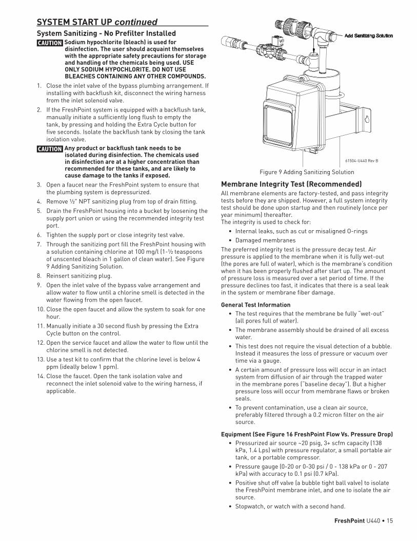
6. Tighten the supply port or close integrity test valve.7. Through the sanitizing port fill the FreshPoint housing with
a solution containing chlorine at 100 mg/l (1-½ teaspoons of unscented bleach in 1 gallon of clean water). See Figure 9 Adding Sanitizing Solution.
8. Reinsert sanitizing plug.9. Open the inlet valve of the bypass valve arrangement and
allow water to flow until a chlorine smell is detected in the water flowing from the open faucet.
10. Close the open faucet and allow the system to soak for one hour.
11. Manually initiate a 30 second flush by pressing the Extra Cycle button on the control.
12. Open the service faucet and allow the water to flow until the chlorine smell is not detected.
13. Use a test kit to confirm that the chlorine level is below 4 ppm (ideally below 1 ppm).
14. Close the faucet. Open the tank isolation valve and reconnect the inlet solenoid valve to the wiring harness, if applicable.
SYSTEM START UP continued
Figure 9 Adding Sanitizing Solution
Membrane Integrity Test (Recommended)All membrane elements are factory-tested, and pass integrity tests before they are shipped. However, a full system integrity test should be done upon startup and then routinely (once per year minimum) thereafter. The integrity is used to check for:
• Internal leaks, such as cut or misaligned O-rings• Damaged membranes
The preferred integrity test is the pressure decay test. Air pressure is applied to the membrane when it is fully wet-out (the pores are full of water), which is the membrane’s condition when it has been properly flushed after start up. The amount of pressure loss is measured over a set period of time. If the pressure declines too fast, it indicates that there is a seal leak in the system or membrane fiber damage.
General Test Information• The test requires that the membrane be fully “wet-out”
(all pores full of water).• The membrane assembly should be drained of all excess
water.• This test does not require the visual detection of a bubble.
Instead it measures the loss of pressure or vacuum over time via a gauge.
• A certain amount of pressure loss will occur in an intact system from diffusion of air through the trapped water in the membrane pores (“baseline decay”). But a higher pressure loss will occur from membrane flaws or broken seals.
• To prevent contamination, use a clean air source, preferably filtered through a 0.2 micron filter on the air source.
Equipment (See Figure 16 FreshPoint Flow Vs. Pressure Drop)• Pressurized air source ~20 psig, 3+ scfm capacity (138
kPa, 1.4 Lps) with pressure regulator, a small portable air tank, or a portable compressor.
• Pressure gauge (0-20 or 0-30 psi / 0 - 138 kPa or 0 - 207 kPa) with accuracy to 0.1 psi (0.7 kPa).
• Positive shut off valve (a bubble tight ball valve) to isolate the FreshPoint membrane inlet, and one to isolate the air source.
• Stopwatch, or watch with a second hand.
61504-U440 Rev B
FreshPoint U440 • 15
Integrity Test Procedure1. Ensure that the membrane is fully “wet-out” by operating
the system at its maximum flow rate for at least 20 minutes by opening the nearest tap downstream.
2. Isolate the system by closing the inlet valve of the bypass plumbing arrangement.
3. If the system is installed with the optional flush tank, close the valve to the flush tank.
4. If installed with a backflush kit, disconnect the wiring harness from the inlet solenoid valve.
5. Depressurize the system by pressing and holding the Extra Cycle button for five seconds.
6. Open the nearest downstream faucet to allow air to escape during the test, or crack open the outlet union.
7. Drain the module by opening the ¼” ball valve at the bottom of the module and pressing and holding the Extra Cycle button on the control for five seconds to open the drain solenoid valve.
8. The drain solenoid valve will need to be opened repeatedly using the Extra Cycle button until there is no further evidence of water draining from the module.
9. Connect the Technician’s Decay Test Components, Figure 16 FreshPoint Flow Vs. Pressure Drop, with the quick connect fitting to the valve at the bottom of the module (see Figure 16 FreshPoint Flow Vs. Pressure Drop).
NOTE: Test the system first for plumbing leaks by closing the downstream faucet and/or connecting the outlet union, and performing steps 11 through 13. Pressure decay with outlet plumbing closed indicates a leak in the plumbing or valves, and the plumbing connections should be tightened or replaced and the system retested until the plumbing passes. In the event a drain solenoid is leaking, actuating a flush a few times may cause it to seat. If not, it should be replaced.
10. Turn on the air compressor.11. With the drain solenoid valve closed, carefully pressurize
the feed side (the inside of the fiber lumens) to 15.1 psi (1.04 bar or 104 kPa) to 15.4 psi (1.06 bar or 106 kPa) by pressing the air compressor hose chuck onto the air supply valve on the Technician’s Decay Test Components, Figure 16 FreshPoint Flow Vs. Pressure Drop. DO NOT PERMIT THE MODULE TO BE PRESSURIZED TO GREATER THAN 16 PSI (1.1 bar or 110 kPa).
12. Turn off the air compressor.13. Begin timing the pressure decay when the pressure falls to
15.0 psi (1.03 bar or 103 kPa).14. Record the pressures at 30, 60, 90, and 120 seconds.15. Once the plumbing has passed the test, test the membrane
and membrane seals by opening the nearest downstream faucet to allow air to escape during the test, or crack open the outlet union.NOTE: A membrane that is not properly wet-out or has been
sitting for some time may cause a false failure. Ensure that the membrane has been flushed properly before performing the Integrity Test. Acceptance Criteria: After two minutes, the system should not have decayed from 15.0 psi (1.03 bar or 103 kPa) to less than 14.5 psi (0.99 bar or 100 kPa).
16. If the system fails to hold pressure, verify the integrity of the inlet and drain plumbing by closing the outlet valve of the bypass plumbing arrangement and repeating steps 10 through 14.
SYSTEM START UP continuedNOTE: Pressure decay with outlet plumbing closed
indicates a leak in the plumbing or valves, and the plumbing connections should be tightened or replaced and the system retested until the plumbing passes. In the event a drain solenoid is leaking, actuating a flush a few times may cause it to seat. If not, it should be replaced.
Air Compressor
Quick-Disconnect Fitting
0.2 Micron Air FilterShut-Off Valve
TeePressure Gauge
Air Fill Valve
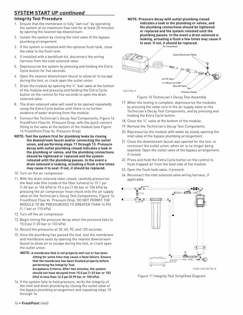
Figure 10 Technician's Decay Test Assembly17. When the testing is complete, depressurize the modules
by pressing the valve core in the air supply valve on the Technician’s Decay Test Components, and by pressing and holding the Extra Cycle button.
18. Close the ¼" valve at the bottom of the module.19. Remove the Technician’s Decay Test Components.20. Repressurize the module with water by slowly opening the
inlet valve of the bypass plumbing arrangement.21. Close the downstream faucet was opened for the test, or
reconnect the outlet union, when air is no longer being expelled. Open the outlet valve of the bypass arrangement, if closed.
22. Press and hold the Extra Cycle button on the control to flush trapped air from the feed side of the module.
23. Open the flush tank valve, if present.24. Reconnect the inlet solenoid valve wiring harness, if
applicable.
Figure 11 Integrity Test Simplified Diagram
61504-U440-BF Rev B
42613 Rev A
16 • FreshPoint U440
MULTI-UNIT FRESHPOINT INSTALLATIONParallel arrangements of FreshPoint modules should be considered to provide service flow rates greater than that available from a single module, while lowering the cost and simplifying the system by programming the units together only once. Controls can be wired and programmed to sequentially backflush up to four modules, thus minimizing the demand on the Backflush Tank and the impact on the service flow rate.
Equipment Required (Two Membrane System)Item Qty Description PN
1 2 FreshPoint System with Control 61788-01
2 1 Backflush Kit with Tank 61667-11
3 1 Multi-Unit System Kit 4002815
4 1 Inlet Solenoid Kit 4002788
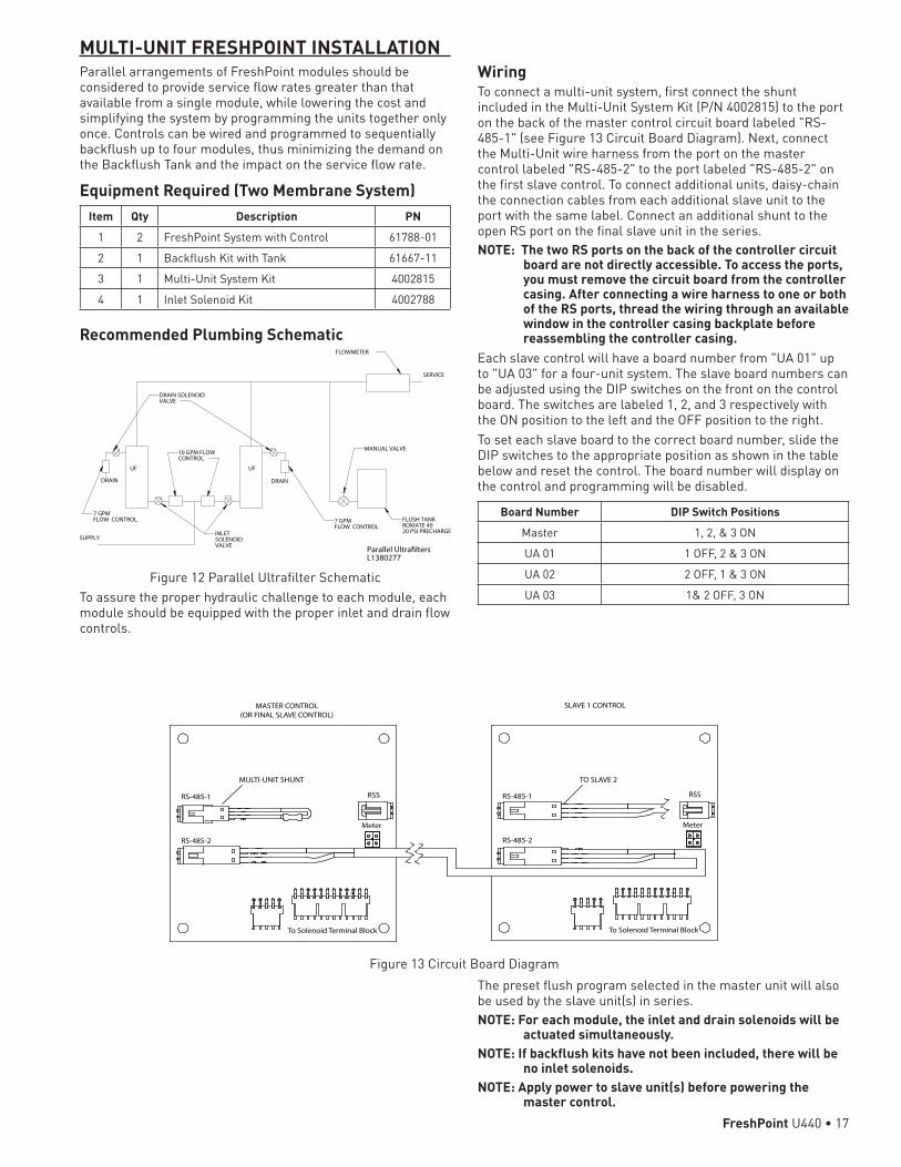
Recommended Plumbing Schematic
Parallel UltrafiltersL1380277
SUPPLY
7 GPMFLOW CONTROL 7 GPM
FLOW CONTROL
DRAIN DRAIN
10 GPM FLOWCONTROL
UF UF
FLUSH TANKROMATE 4020 PSI PRECHARGE
FLOWMETER
MANUAL VALVE
INLETSOLENOIDVALVE
DRAIN SOLENOID VALVE
SERVICE
Figure 12 Parallel Ultrafilter SchematicTo assure the proper hydraulic challenge to each module, each module should be equipped with the proper inlet and drain flow controls.
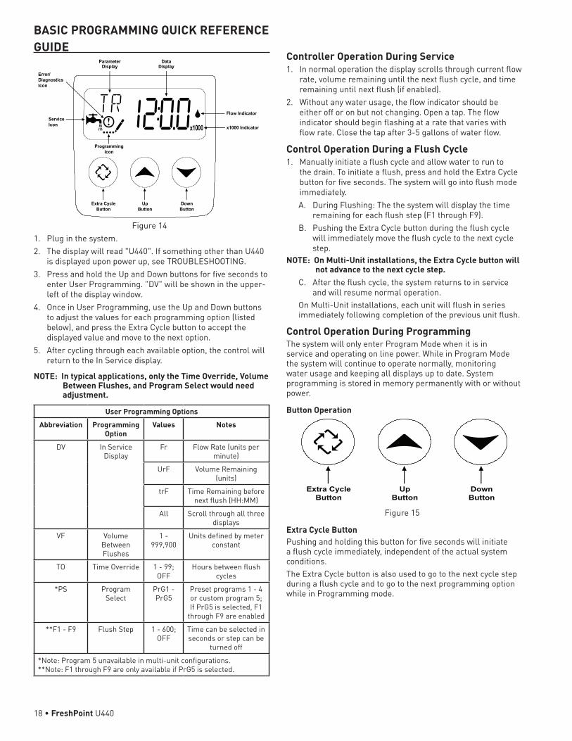
WiringTo connect a multi-unit system, first connect the shunt included in the Multi-Unit System Kit (P/N 4002815) to the port on the back of the master control circuit board labeled "RS-485-1" (see Figure 13 Circuit Board Diagram). Next, connect the Multi-Unit wire harness from the port on the master control labeled "RS-485-2" to the port labeled "RS-485-2" on the first slave control. To connect additional units, daisy-chain the connection cables from each additional slave unit to the port with the same label. Connect an additional shunt to the open RS port on the final slave unit in the series.NOTE: The two RS ports on the back of the controller circuit
board are not directly accessible. To access the ports, you must remove the circuit board from the controller casing. After connecting a wire harness to one or both of the RS ports, thread the wiring through an available window in the controller casing backplate before reassembling the controller casing.
Each slave control will have a board number from "UA 01" up to "UA 03" for a four-unit system. The slave board numbers can be adjusted using the DIP switches on the front on the control board. The switches are labeled 1, 2, and 3 respectively with the ON position to the left and the OFF position to the right. To set each slave board to the correct board number, slide the DIP switches to the appropriate position as shown in the table below and reset the control. The board number will display on the control and programming will be disabled.
Board Number DIP Switch PositionsMaster 1, 2, & 3 ON
UA 01 1 OFF, 2 & 3 ON
UA 02 2 OFF, 1 & 3 ON
UA 03 1& 2 OFF, 3 ON
RS-485-1
RS-485-2
Meter
To Solenoid Terminal Block
RSS
MULTI-UNIT SHUNT
RS-485-1
RS-485-2
Meter
To Solenoid Terminal Block
RSS
MASTER CONTROL (OR FINAL SLAVE CONTROL)
SLAVE 1 CONTROL
TO SLAVE 2
Figure 13 Circuit Board DiagramThe preset flush program selected in the master unit will also be used by the slave unit(s) in series. NOTE: For each module, the inlet and drain solenoids will be
actuated simultaneously. NOTE: If backflush kits have not been included, there will be
no inlet solenoids. NOTE: Apply power to slave unit(s) before powering the
master control.FreshPoint U440 • 17
Controller Operation During Service1. In normal operation the display scrolls through current flow
rate, volume remaining until the next flush cycle, and time remaining until next flush (if enabled).
2. Without any water usage, the flow indicator should be either off or on but not changing. Open a tap. The flow indicator should begin flashing at a rate that varies with flow rate. Close the tap after 3-5 gallons of water flow.
Control Operation During a Flush Cycle1. Manually initiate a flush cycle and allow water to run to
the drain. To initiate a flush, press and hold the Extra Cycle button for five seconds. The system will go into flush mode immediately.A. During Flushing: The the system will display the time
remaining for each flush step (F1 through F9). B. Pushing the Extra Cycle button during the flush cycle
will immediately move the flush cycle to the next cycle step.
NOTE: On Multi-Unit installations, the Extra Cycle button will not advance to the next cycle step.
C. After the flush cycle, the system returns to in service and will resume normal operation.
On Multi-Unit installations, each unit will flush in series immediately following completion of the previous unit flush.
Control Operation During ProgrammingThe system will only enter Program Mode when it is in service and operating on line power. While in Program Mode the system will continue to operate normally, monitoring water usage and keeping all displays up to date. System programming is stored in memory permanently with or without power.
Button Operation
Extra CycleButton
UpButton
DownButton
Figure 15
Extra Cycle ButtonPushing and holding this button for five seconds will initiate a flush cycle immediately, independent of the actual system conditions.The Extra Cycle button is also used to go to the next cycle step during a flush cycle and to go to the next programming option while in Programming mode.
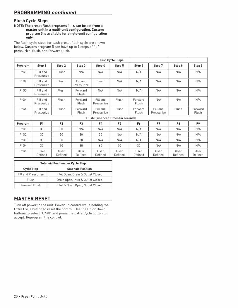
BASIC PROGRAMMING QUICK REFERENCE GUIDE
Figure 14 1. Plug in the system.2. The display will read "U440". If something other than U440
is displayed upon power up, see TROUBLESHOOTING.3. Press and hold the Up and Down buttons for five seconds to
enter User Programming. "DV" will be shown in the upper-left of the display window.
4. Once in User Programming, use the Up and Down buttons to adjust the values for each programming option (listed below), and press the Extra Cycle button to accept the displayed value and move to the next option.
5. After cycling through each available option, the control will return to the In Service display.
NOTE: In typical applications, only the Time Override, Volume Between Flushes, and Program Select would need adjustment.
User Programming OptionsAbbreviation Programming
OptionValues Notes
DV In Service Display
Fr Flow Rate (units per minute)
UrF Volume Remaining (units)
trF Time Remaining before next flush (HH:MM)
All Scroll through all three displays
VF Volume Between Flushes
1 - 999,900
Units defined by meter constant
TO Time Override 1 - 99; OFF
Hours between flush cycles
*PS Program Select
PrG1 - PrG5
Preset programs 1 - 4 or custom program 5; If PrG5 is selected, F1
through F9 are enabled
**F1 - F9 Flush Step 1 - 600; OFF
Time can be selected in seconds or step can be
turned off
*Note: Program 5 unavailable in multi-unit configurations. **Note: F1 through F9 are only available if PrG5 is selected.
Parameter Display
Data Display
Flow Indicator
x1000 Indicator
Service Icon
Programming Icon
Extra Cycle Button
Up Button
Down Button
Error/DiagnosticsIcon
18 • FreshPoint U440

Up/Down ButtonsThese buttons are used to enter into Programming mode and to adjust programming options.
Master Programming1. To enter Master Programming:
A. Enter into User Programming by pressing and holding the Up and Down buttons for five seconds. Release when "DV" is shown in the upper-left of the displayed.
B. Use the Up and Down buttons to change the value of "DV" to "All".
C. Press and hold the Up and Down buttons for an additional five seconds until "NU" is shown in the upper-left corner of the display.
2. Once in Master Programming, use the Up and Down buttons to adjust the values for each programming option (listed below), and press the Extra Cycle button to accept the displayed value and move to the next option.
3. After cycling through each available option, the control will return to the In Service display.
Master Programming OptionsAbbreviation Programming
OptionValues Notes
NU Number of Units
1 - 4 Default is 1; up to 4 total units in series
MC Meter Constant
1.0 - 999.9
Default is 65.0; pulses per unit volume of flow
meter
SD System Service
Interval Days
1 - 365 (Time
Clock); OFF
Default is OFF; days until system service
reminder (ERR 1)
SV System Service Interval Volume
0 - 999.9 x1000 Units
Default is 0; units of volume until system
service reminder (ERR 1)
RF Remote Flush 1 - 999 Default is 60; seconds of continuous contact closure to start flush
NOTE: The default meter constant value is 65.0 pulses per unit volume, which is ideal for measuring flow in gallons. To measure flow in liters, the meter constant value should be changed to 17.2.
Diagnostic DisplayThe Diagnostic Display shows read-only diagnostic data that may be useful when servicing the system. Diagnostic data is indicated by a (!) icon in the lower left corner of the display.1. To view the Diagnostic Display, press and hold the Extra
Cycle and Up buttons for five seconds while in service. The (!) icon will appear in the lower left corner of the display.
2. Use the Up and Down buttons to scroll through the diagnostic options (listed below).
3. Press the Extra Cycle button to exit the Diagnostic Display and return to service.
Diagnostic Display OptionsAbbreviation Diagnostic
OptionValues Notes
TF Totalizer 0 - 999.9 x1000
Water used since reset
VL Volume since last flush
User specified
Units definted by meter constant
TL Time since last flush
User specified
Hours since last flush
V2 Volume used between last two flushes
User specified
Units definted by meter constant
T2 Time between last two flushes
User specified
Defined in hours
SD Days since system
serviced
Set in Master Programming
Defined in days
Reset with system service reminder or by changing SD
value in Master Programming
SV Volume since system
serviced
Set in Master Programming
Units defined by meter constant
Reset with system service reminder or by changing SV
value in Master Programming
SW Software version
PROGRAMMING continued
FreshPoint U440 • 19
Flush Cycle StepsProgram Step 1 Step 2 Step 3 Step 4 Step 5 Step 6 Step 7 Step 8 Step 9
PrG1 Fill and Pressurize
Flush N/A N/A N/A N/A N/A N/A N/A
PrG2 Fill and Pressurize
Flush Fill and Pressurize
Flush N/A N/A N/A N/A N/A
PrG3 Fill and Pressurize
Flush Forward Flush
N/A N/A N/A N/A N/A N/A
PrG4 Fill and Pressurize
Flush Forward Flush
Fill and Pressurize
Flush Forward Flush
N/A N/A N/A
PrG5 Fill and Pressurize
Flush Forward Flush
Fill and Pressurize
Flush Forward Flush
Fill and Pressurize
Flush Forward Flush
Flush Cycle Step Times (in seconds)Program F1 F2 F3 F4 F5 F6 F7 F8 F9
PrG1 30 30 N/A N/A N/A N/A N/A N/A N/A
PrG2 30 30 30 30 N/A N/A N/A N/A N/A
PrG3 30 30 30 N/A N/A N/A N/A N/A N/A
PrG4 30 30 30 60 30 30 N/A N/A N/A
PrG5 User Defined
User Defined
User Defined
User Defined
User Defined
User Defined
User Defined
User Defined
User Defined
Solenoid Position per Cycle StepCycle Step Solenoid Position
Fill and Pressurize Inlet Open, Drain & Outlet Closed
Flush Drain Open, Inlet & Outlet Closed
Forward Flush Inlet & Drain Open, Outlet Closed
PROGRAMMING continuedFlush Cycle StepsNOTE: The preset flush programs 1 - 4 can be set from a
master unit in a multi-unit configuration. Custom program 5 is available for single-unit configuration only.
The flush cycle steps for each preset flush cycle are shown below. Custom program 5 can have up to 9 steps of fill/pressurize, flush, and forward flush.
MASTER RESETTurn off power to the unit. Power up control while holding the Extra Cycle button to reset the control. Use the Up or Down buttons to select "U440" and press the Extra Cycle button to accept. Reprogram the control.
20 • FreshPoint U440

SERVICE AND MAINTENANCEWhen to call the DealerIf problems are experienced with the installation or operation of the FreshPoint system, refer to the troubleshooting guide in this service manual, or contact your FreshPoint Distributor for assistance.
MonitoringIf changes to the flow rate or pressure are noticed, contact the installer to get recommendations on changing flushing settings, and/or have the system evaluated by the installer. Many factors can cause a change in pressure. As water temperature decreases, the flow available from the FreshPoint system will also decrease for the same inlet pressure. The flow rate will drop or rise approximately 3% for a corresponding 1.8F° (1C°) drop or rise in water temperature. Prefilter plugging will cause a decrease in available pressure. Additionally, if a noticeable loss of pressure is detected over time, the current flushing schedule may not be sufficient to prevent fouling, and additional flushing will be required. Refer to the Troubleshooting section in this service manual to address this and other issues.
Prefilter ChangesThe prefilter should be changed as recommended by the manufacturer. Generally, change the cartridge when a decrease in pressure is noted, or after six months installed.
Membrane MaintenanceThe FreshPoint membrane must be kept in a wetted condition. Once installed or during service and maintenance activities, do not allow the FreshPoint membrane to sit completely drained for extended periods (greater than 12 hours). Failure to do so may damage the system. If the FreshPoint system is drained or out of service for an extended period of time, the installer/dealer should put a preservative into the system to keep the membrane wetted and prevent microbial growth. A 0.1% sodium bisulfite solution is recommended. A 0.1% sodium bisulfite solution would be 1 gram of sodium bisulfite added to one liter of water (approximately ten liters are required). Prior to putting the FreshPoint back into service, the system should be flushed and sanitized per the instructions in the Installation section of this service manual.
Membrane CleaningMembrane cleaning is required when the surface of the membrane and membrane pores become fouled. This is most often detected by a loss of flow rate. The FreshPoint membranes should be maintained in a clean condition, unfouled by particulate matter, precipitates or biological growth. Contact your FreshPoint Distributor for cleaning.
Membrane Storage After UseAfter initial use the membranes need to be kept wet at all times. To avoid biological growth during shutdowns or storage, wet membranes should be treated with a compatible biocide. • Downtime up to 24 hours - no measures required.• Downtime 1 to 15 days – Automatic flushing
Systems that are equipped with automatic time based flush systems (and feed water is available) can continue to flush automatically provided the flush cycle occurs at least every 24 hours for a minimum of 30 seconds.
• Downtime Over 15 days – Automatic flushing
Systems that are equipped with automatic time based flush systems (and feed water is available) can continue to flush automatically provided the flush cycle occurs at least every 24 hours for a minimum of 60 seconds.
• Downtime > 7 days – No Automatic flushing / Membranes stored in place Membranes should be cleaned and disinfected. The system should be put in bypass. Then fill with a 0.1% sodium bisulfite solution. Leave membranes installed in the system.
CAUTION DO NOT FREEZE! Take precautions to ensure the FreshPoint system is not exposed to freezing temperatures.
In all cases the membranes must be stored hydraulically filled.CAUTION Any time a storage solution is used the membranes
must be flushed and sanitized prior to use. See Membrane Flushing & Disinfection guidelines. An integrity test is recommended.
To replace the Membrane Element:1. Use the bypass valve to bypass the system. Isolate the
backflush tank, if applicable.2. Run a manual flush by pressing and holding the Extra Cycle
button for five seconds until water no longer comes out of the drain port.
3. If installed, use the integrity test port to drain the system. It may be useful to open the drain by running a manual flush to help draining.
4. Unplug the power cord leading to the system and gently disconnect the cord leading to the flow meter and the wire harness(es) leading to the solenoid valve(s).
5. Slowly disconnect the inlet fitting union (located closest to the floor). This will allow any remaining water to drain from the system.
6. Slowly disconnect one end of the PEX tubing from the drain solenoid valve by pushing in the connector collar and pulling out the tubing.
7. Slowly disconnect one end of the meter assembly from the outlet assembly.
8. Loosen the four mounting bolts that fasten the FreshPoint to the wall. Lift the system up slightly and pull away from the wall.
9. Remove the end caps, and slide the membrane element out of the membrane housing (both end caps may need to be removed so the element can be pushed out of the housing).
10. Lubricate the O-rings sparingly with silicone. Replace the end cap on the bottom of the vessel.
11. Install the spacer spring.12. Gently slide the new membrane element into the housing.
NOTE: The open distributor tube of the membrane should be oriented up.
CAUTION DO NOT DROP THE MEMBRANE ELEMENT INTO HOUSING-THIS COULD DAMAGE THE MEMBRANE ELEMENT.
13. Gently and firmly slide the top adaptor with O-rings into the membrane elements center tube, and secure the end cap.
14. Remount the FreshPoint and reattach plumbing. Reconnect the meter cable and wire harness(es).
15. Put the unit back into service with the bypass valve. Before using system, perform flushing and sanitizing procedures as listed in the Installation section of this service manual.
FreshPoint U440 • 21

Problem Cause CorrectionSystem controller does not have power.
The system is not plugged in. Plug the system controller in.
Display shows "HS" or "SC" upon power up.
Control set for wrong system. Power up control while holding the Extra Cycle button to reset control. Use the Up or Down buttons to select "U440" and press Extra Cycle button to accept.
Single unit display shows "UA Ox" upon power up.
Control has been set as a multi-unit slave.
Set all control DIP switches to ON and cycle power to control. See MULTI-UNIT FRESHPOINT INSTALLATION.
There is no product water flow to the house.
Bypass valves are not in the correct positions to allow water flow to the house, or supply water is unavailable.
Restore supply flow to the system.
Cartridge in prefilter is plugged. Replace or clean the filter cartridge.FreshPoint membrane is fouled. Contact your FreshPoint dealer for service.
There is low flow or pressure available.
FreshPoint is flushing. Wait for flush to end. If desired, have a pressure tank installed after system to maintain pressure during flush. If flushing continuously, see "System is flushing continuously" below.
Unit is not flushing frequently enough. Decrease the volume between flushes, and/or increase the flush time.
Inlet water pressure is too low. Boost the inlet water pressure.Cartridge in prefilter is plugged. Replace or clean the filter cartridge.FreshPoint membrane is fouled. Contact your FreshPoint dealer for service.Incoming water temperature is too low. Contact your FreshPoint dealer for options to
compensate for low water temperature.System is flushing continuously.
Drain solenoid valve is stuck open. Replace the drain solenoid valve.System controller circuit board is sending flush signal continuously.
Contact your FreshPoint dealer for service.
System is not flushing. The system is not plugged in. Plug the system controller in.Drain solenoid valve is stuck closed. Replace the solenoid valve.Meter is not reading flow. Check the connection of meter cable to meter, secure if
necessary.System controller circuit board is not sending flush signal.
Contact your FreshPoint dealer for service.
Meter is not reading flow. Meter cable is not secured to meter body. Check the connection of meter cable to meter, and secure if necessary.
Meter or controller are malfunctioning. Contact your FreshPoint dealer for service.Water leaks at the end of the filter cartridge after changing cartridge.
Cartridge end connections are not tight enough.
Tighten with wrench if necessary.
O-rings are not properly lubricated. Lubricate O-rings.O-rings are cut, or deformed. Replace O-rings.
System controller display is blank.
The system controller is not plugged in. Plug the system controller in.System controller circuit board is malfunctioning.
Contact your FreshPoint dealer for service.
Water has an unpleasant taste and/or suds when being drawn.
Unit has not been flushed sufficiently at startup.
Open all faucets in the house, and let water flow for 20 minutes, starting at the faucet closest to the system.
Water splashes at drain during flush.
Drain line not positioned properly. Reposition the end of the drain line.
Backflush flow stops before end of flush cycle.
High flush tank precharge pressure. Adjust flush tank precharge pressure to 20 psi (138 kPa).
Backflush tank is too small for flush and service usage.
Install a larger backflush tank.
Water leaks at the end of the membrane housing.
Seal missing or damaged. Replace seal.
TROUBLESHOOTING
22 • FreshPoint U440

Error MessagesMessage Description Correction
ERR1 Service Volume or Service Days has expired Press the Extra Cycle button to clear. The service volume and days will be reset.
ERR2 Communication error Check dip switches and communication cable connections and cycle power to controller. If a multi-unit system, turn off power to all units, correct cable or switch issues and restore power first to slave unit(s), then to master unit.
FLOW RATE VS. DRIVING PRESSURE
Figure 16 FreshPoint Flow Vs. Pressure DropNOTE: Curves are shown for a clean membrane at various
water temperatures.NOTE: Flow decreases 3% for each 1.8F° (1C°) decrease in
feed water temperature.
APPENDIX A - PERFORMANCE MONITORINGThe consistency of performance of the ultrafilter membrane can be assessed by measuring the transmembrane pressure (TMP)*, filtrate flow rate, and water temperature and comparing the results to the unit’s previous performance. Most beneficial is to have the data from when the membrane was first installed for comparison.
Establishing Initial Conditions1. If a flush tank has been installed, isolate it by closing the
ball valve.2. Open the faucet closest to the FreshPoint system.3. Record the filtrate flow rate as reported by the FreshPoint
controller as Finitial.4. Record the pressure at the UF module inlet as Pinitial.5. Record the known or estimated water temperature as
Tinitial.Assess the current performance of the ultrafilter membrane by normalizing its current performance to its initial performance as follows:6. If a flush tank has been installed, isolate it by closing the
ball valve.7. Open the faucet closest to the FreshPoint system. This
should be the same faucet used during the initial testing.8. Record the filtrate flow rate as reported by the FreshPoint
controller as Fcurrent.
9. Record the pressure at the UF module inlet as Pcurrent.10. Record the known or estimated water temperature as
Tcurrent. If the water temperature is assumed to not have changed, this term of the equation will reduce to 1.
11. Calculate the current flow rate normalized to the initial performance by the following equation:Fnormalized = Fcurrent*[ Pinitial/ Pcurrent]*[1+( Tinitial°F- Tcurrent°F)*0.017]
*TMP will be approximated by the inlet pressure, measured at the center ½" NPT port in the bottom head, when a faucet near the UF system is opened.
357707 .........................Stainless Steel Vessel Assy, U44061595-03 .....................UF Filter Element Assy, 4"41972 ...........................Bracket, Mounting, UF Filter41976 ...........................Clamp Assy, UF Filter4002963 .......................Timer, Service, U440, 24VDC357716 .........................Fitting Kit, Inlet, U44060700-10 .....................DLFC, ¾” F x ¾” F NPT, 10 gpm4002792 .......................Fitting Kit, Outlet, U44061823 ...........................Kit, 1" Turbine w/ ¾" NPT4002793 .......................Fitting Kit, Drain, U4404002607 .......................Solenoid Assy, U440, DC, Drain, NC60699-70 .....................DLFC, ¾"F NPT, 7.0 gpm357719 .........................UF Adapter Kit, 357707/615954002788 .......................Inlet Solenoid Kit, DC4002786 .......................Outlet Solenoid Kit, DC
See FreshPoint Pricing Guide for complete list of service parts, assemblies, and pricing.
SERVICE ASSEMBLIES
TROUBLESHOOTING continued
FreshPoint U440 • 23

For Pentair Product Warranties visit: Pentair para las garantías de los productos visite:
Pour Pentair garanties produit visitez le site : waterpurification.pentair.com}
WATER QUALITY SYSTEMS5730 NORTH GLEN PARK ROAD, MILWAUKEE, WI 53209 P: 262.238.4400 | 800.279.9404 | waterpurification.pentair.com | [email protected] Pentair trademarks and logos are owned by Pentair, Inc. All other brand or product names are trademarks or registered marks of their respective owners. Because we are continuously improving our products and services, Pentair reserves the right to change specifications without prior notice. Pentair is an equal opportunity employer.4002816 Rev E JA16 ©2016 Pentair Residential Filtration, LLC All Rights Reserved.


