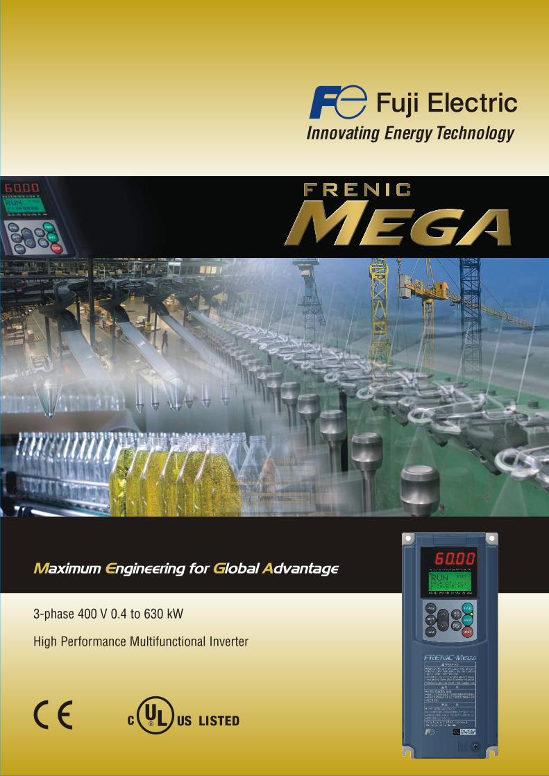
3-phase 400 V 0.4 to 630 kW
High Performance Multifunctional Inverter
Fuji Electric
FRENIC-MEGA is a high performance, multifunctional inver-
ter Fuji Electric has developed by gathering the best of its
technologies.
Now it is ready to answer your needs.
Maximum Engineering for Global Advantage
What is FRENIC-MEGA and what are the advantages?
Able to drive induction and permanent magnet
synchronous motors
Built-in EMC filter as standard
STO compliant to EN 61800-5-2 SIL 2and EN ISO 13849-1 PL d Cat. 3Ability to handle up to 3 simultaneous option cards
(3 ports)
Keypad with a USB connector
Built-in braking transistor up to 22 kW (standard)
and 160 kW (option)
Safety enable input
Full network support
4 complete motor maps
Improved control performance
Motor control methods: PG vector control, sensorless vector
control, dynamic torque vector control, and V/f
control.
Improved performance of current response and speed
response (vector control)
Improved durability in overload operation
HD (high duty) spec: 200% for 3 sec / 150% for 1 min
LD (low duty) spec: 120% for 1 min
Lower maintenance
Maintenance warning output signal
Use of parts with a longer life cycle
Maximizing the performance of a general-
purpose motor by using closed loop vector
control
Effective in providing highly accurate control for applications
such as offset printing, hoisting, winding and wire drawing
Speed control range: 1:1500
Speed response: 100 Hz
Speed control accuracy: ±0.01%
Current response: 500 Hz
Torque accuracy: ±10%
Maximizing the performance of a
general-purpose motor
Sensorless vector control
Useful for applications which require a high starting torque,
such as mixers, extruders and conveyors
Speed control range: 1:200
Speed response: 20 Hz
Speed control accuracy: ±0.5%
Current response: 500 Hz
Torque accuracy: ±10%
Zero speed torque: 100% ± 20%
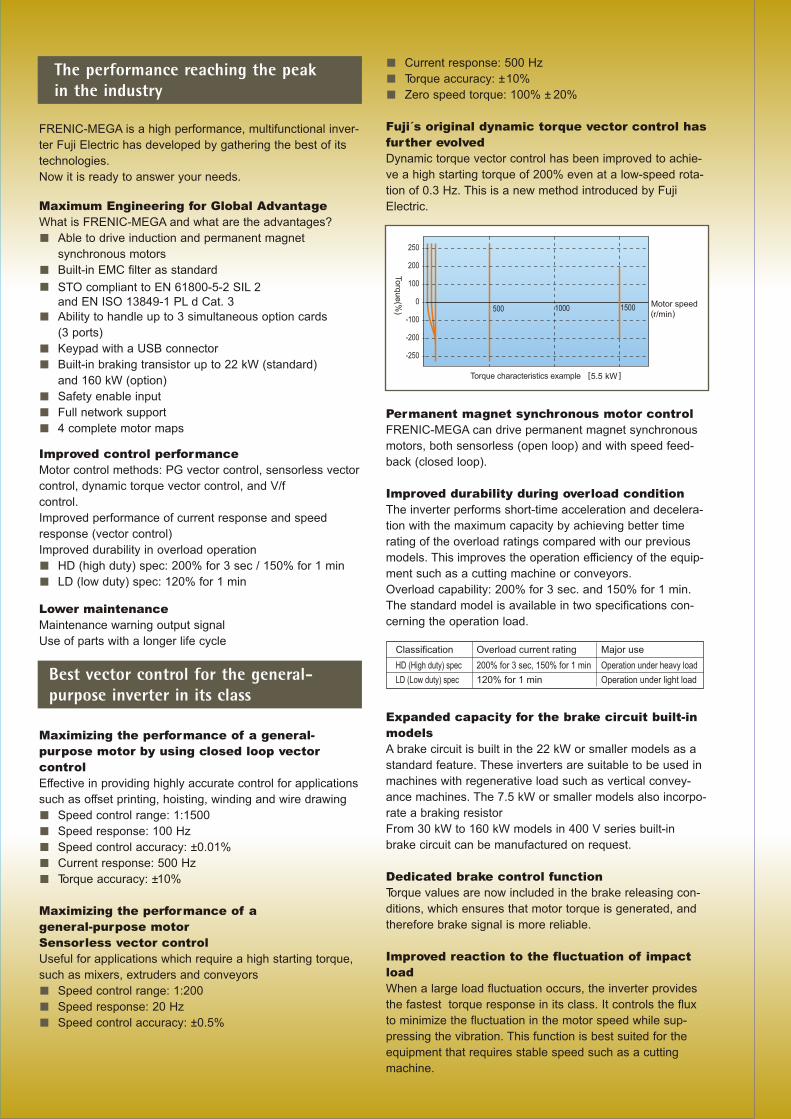
Fuji´s original dynamic torque vector control has
further evolved
Dynamic torque vector control has been improved to achie-
ve a high starting torque of 200% even at a low-speed rota-
tion of 0.3 Hz. This is a new method introduced by Fuji
Electric.
Permanent magnet synchronous motor control
FRENIC-MEGA can drive permanent magnet synchronous
motors, both sensorless (open loop) and with speed feed-
back (closed loop).
Improved durability during overload condition
The inverter performs short-time acceleration and decelera-
tion with the maximum capacity by achieving better time
rating of the overload ratings compared with our previous
models. This improves the operation efficiency of the equip-
ment such as a cutting machine or conveyors.
Overload capability: 200% for 3 sec. and 150% for 1 min.
The standard model is available in two specifications con-
cerning the operation load.
Expanded capacity for the brake circuit built-in
models
A brake circuit is built in the 22 kW or smaller models as a
standard feature. These inverters are suitable to be used in
machines with regenerative load such as vertical convey-
ance machines. The 7.5 kW or smaller models also incorpo-
rate a braking resistor
From 30 kW to 160 kW models in 400 V series built-in
brake circuit can be manufactured on request.
Dedicated brake control function
Torque values are now included in the brake releasing con-
ditions, which ensures that motor torque is generated, and
therefore brake signal is more reliable.
Improved reaction to the fluctuation of impact
load
When a large load fluctuation occurs, the inverter provides
the fastest torque response in its class. It controls the flux
to minimize the fluctuation in the motor speed while sup-
pressing the vibration. This function is best suited for the
equipment that requires stable speed such as a cutting
machine.
Best vector control for the general-purpose inverter in its class
The performance reaching the peak in the industry
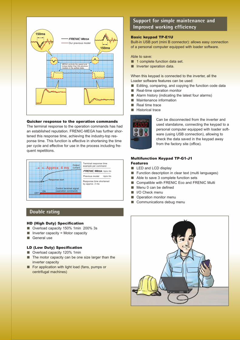
Quicker response to the operation commands
The terminal response to the operation commands has had
an established reputation. FRENIC-MEGA has further shor-
tened this response time, achieving the industry-top res-
ponse time. This function is effective in shortening the time
per cycle and effective for use in the process including fre-
quent repetitions.
HD (High Duty) Specification
Overload capacity 150% 1min 200% 3s
Inverter capacity = Motor capacity
General use
LD (Low Duty) Specification
Overload capacity 120% 1min
The motor capacity can be one size larger than the
inverter capacity
For application with light load (fans, pumps or
centrifugal machines)
Basic keypad TP-E1U
Built-in USB port (mini B connector): allows easy connection
of a personal computer equipped with loader software.
Able to save:
1 complete function data set.
Inverter operation data.
When this keypad is connected to the inverter, all the
Loader software features can be used:
Editing, comparing, and copying the function code data
Real-time operation monitor
Alarm history (indicating the latest four alarms)
Maintenance information
Real time trace
Historical trace
Can be disconnected from the inverter and
used standalone, connecting the keypad to a
personal computer equipped with loader soft-
ware (using USB connection), allowing to
check the data saved in the keypad away
from the factory site (office).
Multifunction Keypad TP-G1-J1
Features
LED and LCD display
Function description in clear text (multi languages)
Able to save 3 complete function sets
Compatible with FRENIC Eco and FRENIC Multi
Menu 0 can be defined
I/O Check menu
Operation monitor menu
Communications debug menu
Support for simple maintenance andImproved working efficiency
Double rating

Wiring diagram
3 analog inputs:
1: ± 10 VDC
2: ± 10 VDC
3: 4-20 mA/PTC
Enable digitalinput (alwaysSOURCE)
9 digital inputs
(SINK or SOURCE
configurable)
X7: Pulse train
digital input (std,
100 kpps)
2 relay digital outputs
4 transistor
digital outputs
2 analog outputs:
0-10 VDC
or 4-20 mA
2 RS 485 ports:
COM1: Keypad
COM2: Terminals
EN1and EN2 digital inputs belong to STO function (always in SOURCE configuration)
For further information about connecting the motor cable shield, please refer to FRENIC-MEGA Instruction Manual, Chapter 9.3 "Compliance with EMC Standards".
Designed life 10 years
For the various consumable parts inside the inverter, their
designed lives have been extended to 10 years, which also
reduces maintenance downtime.
Main circuit capacitor: 10 years
Electrolytic capacitor on PCB: 10 years
Cooling fan: 10 years
The parts life is estimated on condition that the inverter is
used at an ambient air temperature of 40°C and under the
load rate of 100%(HD spec) or 80%(LD spec).
Full support of life warnings
The inverter is loaded with the functions for facilitating the
maintenance of the equipment.
Enhanced resistance to environmental impact
Resistance to the environmental impact has been enhanced
compared with conventional inverters.
(1) Enhanced durability of the cooling fan, reducing environ-
mental impact
(2) Adoption of copper bars plated with nickel (Ni) or tin (Sn)
Each motor (1-4), can be configured by its own function group,
and the control mode for each motor (1-4) can be selected
independently. Each motor can also be tuned independently.
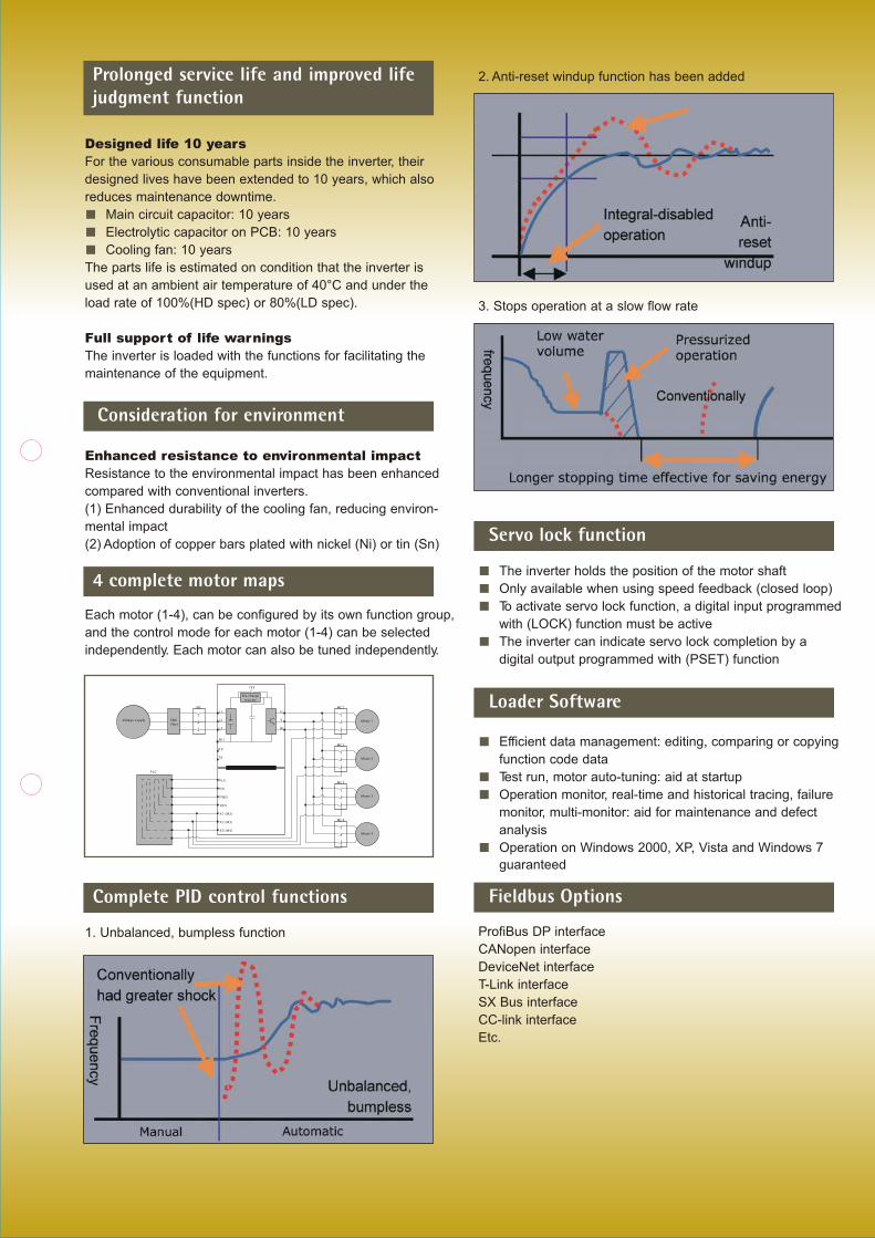
1. Unbalanced, bumpless function
Prolonged service life and improved lifejudgment function
Consideration for environment
4 complete motor maps
2. Anti-reset windup function has been added
3. Stops operation at a slow flow rate
The inverter holds the position of the motor shaft
Only available when using speed feedback (closed loop)
To activate servo lock function, a digital input programmed
with (LOCK) function must be active
The inverter can indicate servo lock completion by a
digital output programmed with (PSET) function
Efficient data management: editing, comparing or copying
function code data
Test run, motor auto-tuning: aid at startup
Operation monitor, real-time and historical tracing, failure
monitor, multi-monitor: aid for maintenance and defect
analysis
Operation on Windows 2000, XP, Vista and Windows 7
guaranteed
ProfiBus DP interface
CANopen interface
DeviceNet interface
T-Link interface
SX Bus interface
CC-link interface
Etc.
Complete PID control functions
Servo lock function
Loader Software
Fieldbus Options
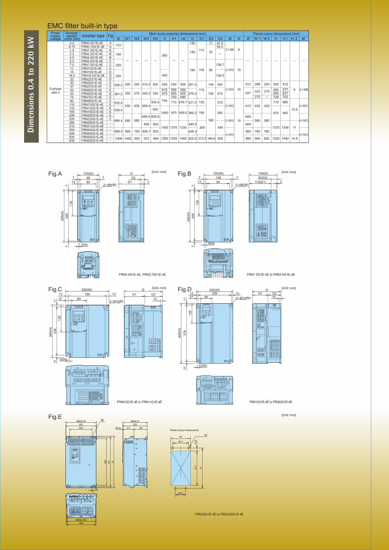
Dim
ensi
ons
0.4
to 2
20 k
W
886.4
1006
880
1000
780
900
659
859.1
972
653
853
966
1400
1550
1370
1520
1330
1480
445.5
446.3
505.9
260
313.2 186.8
440
500
664
864
980
780
900
780
900
1370
1520
1348
1490
11
14.58

Standard Specifications 3ph 400 V series
CEN-G1EN12.10
Subject to change without notice
Fuji Electric
European Headquarters
Fuji Electric Europe GmbH
Goethering 58
63067 Offenbach/Main
Germany
Tel.: +49 (0) 69 669029 0
Fax: +49 (0) 69 669029 58
www.fujielectric.de
Japanese Headquarters
Fuji Electric Co., Ltd.
Gate City Ohsaki East Tower,
11-2 Osaki 1-chome, Shinagawa-ku,
Chuo-ku
Tokyo 141-0032
Japan
Tel: +81 (0) 3 5435 7280
Fax: +81 (0) 3 5435 7425
www.fujielectric.com
France
Fuji Electric Europe GmbH
265 Rue Denis Papin
38090 Villefontaine -FRANCE
Tel.: +33 (0) 4 74 90 91 24
Fax: +33 (0) 4 74 90 91 75
www.fujielectric.de
Spain
Fuji Electric Europe GmbH
Sucursal en España
Rda. Can Fatjo, 5 edif. D local B
Parc Tecnològic del Vallès
08290 Cerdanyola del Vallès (Barcelona)
Tel.: +34 (0) 935 824 333
Fax. +34 (0) 935 824 344
www.fujielectric.de
Italy
Fuji Electric Europe GmbH
Via Rizzotto 46
41126 Modena (MO)
Tel.: +39 059 4734 266
Fax: +39 059 4734 294
www.fujielectric.de
Switzerland
Fuji Electric Europe GmbH
Park Altenrhein
9423 Altenrhein
Tel.: +41 (0) 71 858 29 49
Fax: +41 (0) 71 858 29 40
www.fujielectric.de
United Kingdom
Fuji Electric Europe GmbH
Tel.: +44 (0) 7989 090 783
www.fujielectric.de


