
FP-1500 ADJUSTABLE SMT LEAD FORM AND TRIM SYSTEM
The Manix FP-1500 is the indus-
try’s first automatic flat pack trim
and form system. The system is
capable of cutting and forming two
opposing sides of a component sim-
ultaneously to a SMT or reflow
form.
The system is fully adjustable for
overall cut length, stand-off height,
footpad, component lead thickness,
bend radii, component body size,
and body to first bend.
Component handling is at a mini-
mum. The component is transport-
ed through the various stages auto-
matically. A pick device gently
transports the component to the
form tooling and then to the cut
tooling.
The FP-1500 includes a PLC con-
troller with operation software, a
rugged pneumatic press, a motor-
ized transport mechanism, a fully
adjustable forming and cutting die,
and a centering device that quickly
aligns FP components whether top
or bottom brazed, and or standard
side lead exit. Adjustment software
and a component library ease sys-
tem set-up. Doors with interlocks,
LED lighting and AIRCLEAN cut
lead removal are standard.
PLC Controller includes opera-
tional software and a compo-
nent library which can store all
pertinent component infor-
mation including micrometer
settings, and whether the part
is two or four sided.
Forming and cutting die in-
cludes a motorized transport
system which eliminates opera-
tor handling.
Centering station can accurate-
ly center all two and four sided
flat pack components, includ-
ing bottom and top lead attach-
ment components.
Safety interlocks prevent oper-
ator error.
1650 Loretta Avenue Feasterville, PA 19053 USA
(T) 215-953-9797 (F) 215-953-9399
Email: [email protected] Website: www.manixmfg.com

FP-1500 FEATURES AND BENEFITS
SYSTEM CONTROLS…...
The software and PLC controller are easy to use. A menu-driven con-
troller assures mistake-free operation. A component editor screen re-
tains all of the pertinent information for each component; it can be re-
called at a touch of a screen button. Micrometer settings, component
name, and whether or not the component is two or four sided is some
of the stored information. Maintenance levels and component editor
are password protected. A setup level instructs the operator on set-up.
Alarm menus notify if an alarm is present, if present the system will
not operate.
ADJUSTABLE DIE…...
The FP-1500 forming and cutting die is fully adjustable for com-
ponent body size, footpad length, stand-off height, lead thickness,
bend radii, and body to first bend distance. The three stage die forms
and cuts two sides of a component simultaneously. The first stage
centers the component, ensuring equal forming and cutting. The sec-
ond forms the component to a reflow or SMT form, while retaining
the tie bar. The last stage cuts the component to the proper footpad
length. A transport system includes a cushioned pickup head and a
motorized conveyor. Optional quick change inserts are available for
varying lead thicknesses and inside bend radii. Two lead screw
thumbscrews adjust all other dimensions.
AIRCLEAN, LIGHTING AND MORE…...
Troublesome offcut leads and cut tie bars can be difficult to remove.
The FP-1500 includes AIRCLEAN, a mechanism which directs
air at the cut leads and blows them into a waste collection bin. The
AIRCLEAN activates for a few seconds after the cutting stage.
Two LED lights which can be turned off and on illuminate the entire
work area, making viewing easy.
Interlock switches prevent machine operation if either the side view-
ing windows or the two front doors are open. The PLC prompts the
operator of an alarm condition. Simply close the doors and operation
can continue.

FP-1500 CUTTING AND FORMING SPECIFICATIONS
MIN.(in) MAX.(in) MIN.(mm) MAX.(mm)
A 0.280 2.500 7.12 63.50
B 0.040 1.160 1.01 29.46
C 0.050 1.170 1.27 29.72
D 0 0.220 0 5.59
E 0.090 1.210 2.29 30.73
F Specify Specify Specify Specify
G 0.460 2.680 11.68 68.07
R1 Specify Specify Specify Specify
R2 Specify Specify Specify Specify
Please Note: Dimensions F and R1/R2 are tooling dependent. Quick change inserts are fabricated to your
exacting dimensions. Specifications are dependent on each other. Larger B dimension will reduce maxi-
mum C dimension and the opposite is true. If A is a maximum, B and C are at minimums.

FP-1500 SEQUENCE OF OPERATION
Access the COMPONENT TABLE EDIT screen
and either choose an existing component stored in
the library or create a new one from scratch. Once
chosen, depress SELECT TO RUN.
From the RUN screen, transfer the micrometer set-
tings from the VALUES SELECTED and set the
micrometers to those settings. Before depressing
the START button, load the component onto the
adjustable centering station .
Place the component to be processed in the center-
ing station. Rotate the knurled knob until the cen-
tering anvils just touch the component body. If
the component is a bottom lead attached compo-
nent, use the adjustable lead tip centering station.
Once centered, the system is ready to run.
FP-1500 SEQUENCE OF OPERATION
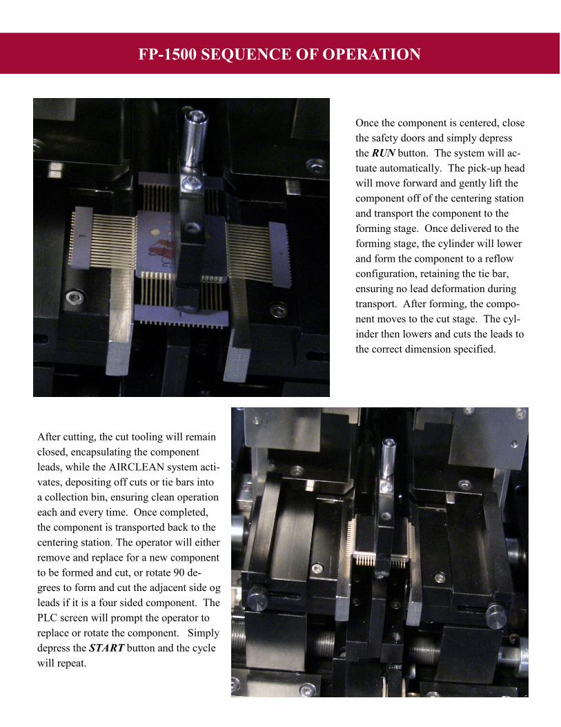
Once the component is centered, close
the safety doors and simply depress
the RUN button. The system will ac-
tuate automatically. The pick-up head
will move forward and gently lift the
component off of the centering station
and transport the component to the
forming stage. Once delivered to the
forming stage, the cylinder will lower
and form the component to a reflow
configuration, retaining the tie bar,
ensuring no lead deformation during
transport. After forming, the compo-
nent moves to the cut stage. The cyl-
inder then lowers and cuts the leads to
the correct dimension specified.
After cutting, the cut tooling will remain
closed, encapsulating the component
leads, while the AIRCLEAN system acti-
vates, depositing off cuts or tie bars into
a collection bin, ensuring clean operation
each and every time. Once completed,
the component is transported back to the
centering station. The operator will either
remove and replace for a new component
to be formed and cut, or rotate 90 de-
grees to form and cut the adjacent side og
leads if it is a four sided component. The
PLC screen will prompt the operator to
replace or rotate the component. Simply
depress the START button and the cycle
will repeat.

FP-1500 SYSTEM SPECIFICATIONS
LOCATION OF MAJOR COMPONENTS
A: PNEUMATIC PRESS
B: PLC CONTROLLER
C: FP-1500 CUTTING/FORMING DIE
D: LED LIGHTING
E: SAFETY DOORS W/INTERLOCKS
F: EMERGENCY STOP, AIR GUAGE,
AND REGULATOR
Dimensions: 19.5”W X 20.5D X 25.5H
495mm X 521mm X648mm
Weight: 250 lbs./114 kgs.
Air: 80 psi dry air required.
Connection: 1/4” or 6mm Tube
Electrical: 110/250 VAC single phase
Switching power supply.
A
B
C
D
E
F
FP-1500 ACCESSORIES:
FP-TBC:
Tie Bar Corner Removal Tool
Quickly remove the ceramic cor-
ners of Tie Bars on flat pack com-
ponents. Simply place the compo-
nent into the tool and lower the
handle. Tie bar corners will snap
off, leaving the tie bars connected
to the leads, ready now for the FP-
1500 cutting and forming system.
M891: Component Measuring Tool
Lead to body exit can vary, making standoff
height setting troublesome. The M891 quick-
ly measure this dimension, ensuring accurate
standoff during forming.
1650 Loretta Avenue
Feasterville, PA 19053 USA
Tel: 215-953-9797 Fax: 215-953-9399
Email: www.manixmfg.com


