
FORGING TECHNOIOGY -- AS APPLIED TO AUTOMOBILE INDUSTRY
S.R.Sharma Forge Division
Tata Engineering & Locomotive Co Ltd Jamshedpur
1. INTRODUCTION
Metals and alloys have the ability to be formed into useful
shapes by Plastic Deformation. In this process they also develop a
wide range of properties particularly strength and toughness. The
working of the metals into shapes by means of forging methods refines
grain structure, develops inherent strength giving characteristics,
improves physical properties and produces structural uniformity free
from hidden internal defects. Moreover, the special feature of flow
lines along the contour of the forging produce marked directional
properties. These features in forgings give the automobile designers
increased confidence regarding the reliability of the vehicle.
2. FEATURES OF FORGINGS PECULIAR TO AUTOMOBILE
An automobile vehicle has to carry loads at high speed and has to
be light enough to ensure fuel economy. In this regard the following
points regarding forgings are noteworthy:
(a) forged components have made possible many design to accommodate higher loads and greater stresses,
(b) because of close tolerances, automated machining lines can be used to machine these at faster rate,
4.1
(c) because of the use of hot-rolled products as input, reliability of internal structure is ensured. As indicated earlier, grain flow characteristics of forg-ings give improved properties of strength, ductility and resistance to impact and fatigue,
(Ref.Fig.1)
(d) because of the controlled sequence of production steps consistency of material composition and structure is assumed from piece to piece and better response to heat treatment is achieved,
(e) with the elimination of internal discontinuities, low rejection rates, better machinability, less machining allowances -- cost of production of aggregates is reduced considerably,
(f) saving in weight of parts is achieved due to the inherent characteristic of higher strength to weight ratio.
Hence many models of auto and trucks contain over 200 separate forgings.
(Ref.Fig.2)
Familiar examples of these items are
Engine components: crank shafts, connecting rods, rocker arms, cam shafts.
Transmission: gear blanks, gear shift levers, drive shaft, main shaft, propeller shaft yokes, flanges brake levers.
Steering: steering shafts, steering levers, pitman arms.
Front axle: front axle beams, stub axles, front hubs.
Rear axle: rear axle shafts, differential cases and covers, crown wheels and pinions, differential gears etc.
(Ref.Fig.3)
In the light of the above it is interesting to know as to how
these forgings are manufactured.
4 . 2

TONG HOLD DRAWN AND EDGED
. WROUGHT BAR STOCK
PREBLOCKED
BLOCKED
FINISHED AND TRIMMED FORGING (ENLARGED)
WROUGHT BAR STOCK
UPSE1
BLOCKED
GRAIN•FLOW LOOPS
.•
FINISHED AND TRIMMED FORGING (ENLARGED)-
Typical sequence of . Typical sequence of steps in forging a disc steps in forging a rib shape. and web shape.
FIG.1.
4.3


Front Axle I Beam
Front Axle I Beam
Shaft End
Crank Shaft
Propellor Shaft
Axle Shaft
Yoke Yoke Splined
Cam Shaft
Subseat
is
41
Pin Anchor Casing Hub Hub
Torque Rod
Arm Shift
Knuckle Arm Knuckle Arm . -"—
Brake Pedal Steering Knuckle Steering Knuckle
MAn PRODUCTS For AUTOMOBILE
Control Lever
FIG.

3. TYPES OF FORGING PROCESSES
Forging processes can be broadly classified as open die and
close die.
3.1 Open Die Forging Process
This process consists of hammering heated metal between a pair of
flat dies. For obtaining the desired rough shapes the skill of the
operator in manipulating the work piece is essential. At times some
helping tools are used to improve the shapes and for special purposes.
This is suitable to the type of production where quantities are small
and sizes of work are large. The type of products produced on these
open frame type pheumatic power hammers are shafts, rings, discs,
large gear blanks etc.
3.2 Close Die Forging Process
This consists of hammering or pressing heated bars or billets
within close impressioned dies. These impressions impart the desired
shape to the work pieces. In view of the many variables in this
process such as material temperature, die condition, machine load,
complexity of job, die lubrication etc the process consists of several
stages of manufacture:
Billet heating Reduce rolling or fullering Bending or flattening (if necessary) Blocker or mould Finish forging
° Billet heating (to around 1250°C) is done in forge furnaces which may be either box type pusher, walking beam, rotary hearth or induction furnaces.
4.6

VaPS FOR DEVELOPMENT OF FORGINGS
MACHINE PART DRAWING + SCHEDULE
OPEN DIE FORGING
FORGING DRAWING
PROCESS OF MFC. PRESS tiA !AMER
UPSETTER
YES MOPEL <
NO
FORGING _DIE DESIGN 'AUX. TOOLING. DESIGN
DIE & TOOL MANUFACTURE-o-----
TRIAL OF JOB
DATA COLLECTION CORRECTIVE ACTION
NOT 0•K
RAW MATERIAL SECTION g SIZE
OWALITY REPORT Q..K
CUSTOMER'S FEED BACK
FIG. 4
4 . 7

o Reduce-rolling is done to distribute the metal to suit forging shape in a separate rolling machine.
o Flattening, bending, blocking and finish forging opera-tions are done in the main forging unit i.e Press or a Hammer.
o Trimming and hot coining operations are done on auxiliary units.
o Heat treatment, shot blasting, grinding etc are.the fini-shing operations, which are done in separate equipments.
o Automobile forgings are made by close die forging process and hence it is essential to elaborate the various features of this technology.
In the first instance designs of the forged part, die and tool design are to be considered.
(Ref.Fig.4)
o Broadly speaking, adding material around the contours of machined piece profile constitutes the design of forged part.
(Ref.Fig.5)
4. STEPS FOR THE DESIGN OF FORGED PART
4.1 Parting Line
Die parting line is the plane which divides the top and bottom
dies in a close die forging. This depends upon the ease of die
filling, forging equipment, grain flow, jib locations and trimming
facility.
Proper parting line avoids deep impressions that might cause die
breakage. This also avoids side thrusts which could cause. excessive
mismatch in forgings (Ref.Fig.6).
4.2 Draft Angles
Draft angles are necessary on all forgings to permit removal of
forgings from dies and to assist in achieving desired metal flow. It

- : • ""
_ . . • • / •
• ?..
•
. • Pt 1.
SKIS F F112.948.1)
•
UNDIIIIR14111••
ARTING:- LINE
t
. • .12 1, Zt 4,-st!4f
• WOMMD •
t
..:4 "ts •
• U NI DES IR AB LE= = = PREFERRED
"- •
t • • ---441 ;
- U N to E. SILAS 1.S.
FIG . 6
4.9
/•• • •
••••••t. •
,.1.••:• • , D
-LA, •
. : f 7:7!•.
. • **.
FE tip#
. •f • ' i ?;:f • . .
. • , • . 44... .
• e ' - 4 X ''' ' 4r, '.PART i Ni 4 1-114 et i?'-. 2:i..4.,;;. )':1:. 1‘ ; :. 7 -; ; . / - , . t „ . • , ..,;,...:. ,-,p, ..-• -:"... '...
B73 C.13./.‘t) t.t tt cal% 14 KICP1...P t! T., !t..4,4.,..P PilE•
F7‘.-. . Co •"' U N it C1%.A Pli 1: RD catt+tact:44:t'-'i-PlE
'. i t D - %ALA 1-iter• c.RANG.14'„P. LI g c. .,,,-• s• . . - .., , •, . . .. , , , ., •-, --!'-----.7 , .. - .
, •;,,-... :3, ,.. i. i SBLIC-TiogIOF PAR:11114Q LINE•
• •
• 7.‘,t• - .•:•;t• " . . . •
- ■•?.
• - t • „ , • • ;
• . Vtil 1 fk131..1 .g!,E...;" k-f..pp.aptutv) ...„ •••• 11 •
• :.' ' • • s3•14i.1•
1 • • ' • r•-.F,
• I •
, • • !. 7.1 • • • • •
- tt: t • : • •
nti▪ f
• 4s. 4 -
i'i-, .....7#•"!".7,:-.4.5. , . 4:4 ,
.. ' ..s. ''' ''.?../1';72:43.■ :.( : .• .: ''. 5 'd • -0 ' I. . .1.i: '' ' f ,, • ;:.f:;.: •
i • •r‘ tb .
•
• •
a •
4R1 V CrtOSCY .. pREFEMUM

= ark• .
L : „
•
e •
••• ■•••••••••... ••,••••(• •■■••••••■
•:.
• •
—4•••••■■•• •••-••••
. ,
• •
•••• • • • •
•
•rt . • ti• • i•tri • •
t . ,- :. • 10 . 'o
4, - -` •G ••; • • ss.t•:' . y • .4.• -••• . - -r“ . • +';',..r.:1%
.,0 4V
,!s 4.1.:
. .. '''.1 • ' Ct • - ' L' -. • : .... . : e
. ,;?,:t, • • • l . • ..i.T. LI. • ., . • — •77 — — tl. ;.4--
• •• • • 1:•'.. ; '•'1 • 1. • • •■• . t , ' : . e . , ' : i • .1.•. • • .. ::;4,1.. 4+-.•- '.• r ;-- iii
• •■'•r'2. e:t.;.0; • " .....ei e, •.. :.• ' , . ? • • „:„...:, !. : .. v.
' . • .-*; 4. 1. - :kb , ., ,• , .•,„ •• ,..v,
- ?..- • . ••• -,•4*..•.:-..t. "•;;:, . ..- .,•`• -*.s..-• h .•.,„ ..1, - . - f ..
. - ..
• PI ; ? '; •
••• . • : • ; • t■-e, ,, •
• '• • -.iv*, ;:y .,.•5&ity.- .4%Mfr
L.
..,••••• • • - • . • .
$••• ;1:.• -* V 't: `• • , • et:. •••• ••• •
ie1:1■1;•';'' i•j 11fr • • t
''4(''‘ s- • • .•
•. •.: 4;4. o •:;i. •
,. . f •'1
;';•• r. ;
4 •
• - • . - ..•r. v . • ;.it• _ . • „r
t t• •
r• :s
.• # ,•; 'd • ' . • 1
tr . 1 • •
i
; 1:••0.
•• . ••••••••••••
.••
.• • rl 0,1 ••'
•
CD • .,it
t Syr • r
• ...r•
t.
• r
•• •
•
`. • 1
• •
r ' • i • r
• • "Pp
• .14
;' • •
• ,, • !
• • n
fa • .
•
, • •.! i•-•••• •
.*s"V"... • s' • . ' . 1 "' • C. -„ • " • ;
r.•;; • tta
• ''• 1 •• .# .••• •'. ."); - - • ,,.. • . • •
g • • P. "
• r• g• r )
-- • •
• , • 1.• '•
.0

is a common practice to follow 3 to 5°C in steel forgings. Excessive
draft angles call for more machining allowances. Forging equipment
also plays a vital part in ascertaining the draft angle. Small draft
angles can be used on press forging dies which have the ejection
systems whereas hammer dies are designed with increased draft angles
(Ref.Fig.7).
4.3 Webs and Ribs
A web is a part of the forging lying parallel to the forging plane, whereas a rib is perpendicular to it. For keeping the forging
weight minimum, the size of these webs and ribs are to be kept under
control, but smaller sizes are influenced by the forging equipment and
the forging temperature. The locations of the parting line and the
fillet radii also affect these (Ref.Fig.8).
4.4 Fillet and Corner Radii
Fillet and corner radii greatly affect the metal flow in a die.
Good fillet radii smoothen out the metal flow and avoid defects of
overlaps bigger fillet radii increase the machining allowances and
weight of the forgings. For achieving smaller fillet radii multi
impression design is considered.
The choice of corner radii is also an important factor because
small corner radii will cause die breakages. This also depends upon
forging weight (Ref.Fig.9).
4.5 Machining Allowances
Machining allowances are controlled by the complexity of the
forging, forging weight, forging equipment and type of furnaces used.
Forging process also controls the machining allowances (Ref.Fig.10).
4.11

P, OFISIMA SOS3SS
•:°
A 8
Usi OF sTRALGHT PARTIN4 LINE' IN port4ost4S CF WEes AT
DiFFEReik3T 41.E.NE6S
A 1
FoRfor4A WHERE R. MUST FOLLOW CE NT RE LINS D1= WEB
5sLF c.or-Aret4sA-r I oN poz4tr.„ TA NDEM,
CIE st
PLActw.q I
a
F iG (CO
4.10

tNESS .3. RIBS )7-7.11-4 El CORN4K RADIl
4.13
8 9
c E NTIRAL.t.4 o cA-T CD 114
is c AT R t) AT ED As Or FORA
V.1 VT Irk R. Pcr TOP
14 _ 12.
10
Er 8 RA; AT GDS,; . OF Ot PORG1P44 a 6
Li)
c?Z 4
LAP occukS 5 2
Too OR. PALLET 700 SMALL
R
E.y.TRUi10/4 1 CI •04 '7 t
t
ti 1-&L
° 07 tt , 11. • Oti H MIN VAt.ut 0$1. h = 1.5 Ynvrt
O
_1 1____ I t t
40 00 IN 0 t2.n 140 2r H EI wr 14. Yvvrk
FIG.8
R tat, H/41 RMIN = pis ,v4.
to s R
I 1 -I - .0 80 110 160 2.0o
NEla 1-17. H
FIG. 9
LAP IF Rig TOO T1-11)3 OR, FtLt.G.T1 TOO
50 -ce
a Q 1°
I.- 2
to a

2. DRAFT INNLE
.111111q
HARMER PR .16 .1
*RAFT 5-10 3-5*
ilDRAFT 7-le 5-7°
NA'T'URAL DRAFT
NATURAL. DRAFT 1N4AER.ENT IN
PART to ES1414.
NATURAL. DRAFT PRON/IpED cj CHANAtNc c'ARTINCt LING
1
OUTS■Al DAAPT
FIG. 7
4.12

4.6 Forging Tolerances
As in other manufacturing processes, there are limitations to the
degree of precision which is practicable in the forgings. Experience
shows that dimensional variations in forgings are common dependent
upon the weight, complexity of shape and materials.
Based on the above concept and other factors such as die wear,
die closure, mismatch etc (Ref.Fig.11) tolerances as per IS:3469 have
been determined for practical use.
4.7 Shapes for Forging
Spherical and block like shapes are the easiest to forge in the
impressioned dies. Parts with thin and long sections are more
difficult because they have more surface area per unit volume.
Vertical bosses such as ribs are harder to forge them laterd
projections.
The increase in load during the progress of forging is gradual
initially, but shoots up as the forging gets filled up (Ref.Fig.12).
5. DIE DESIGN PARAFEITRS
There are no fixed rules for the design of closed die forging
dies since different approaches can often produce acceptable forgings.
There are certain guide-lines and principles, developed by many years
of practical experience which is followed will maximise the probabi-
lity of producing sound forgings with the greatest economy. The
following factors help to produce good forgings.
4.15

tAt"\c-I-ittiNG ALLOWANCES
tNA NcHm11,46 ALLOWANCE,
NOMINAL 14\14 ALLOtkItChiCES _ LT' SORgrACE.
10
6. FoRfcim, TOLM:ZANCES CTS : ulie.)
A. "DIE WEAR
6 LIE CLOSURE C-rHicv.NEsS)
C MISMATCH J ..--
II FLASH ExTENsioN E . SURFAcE CONDITION PITTCRIGs)
F STRAI4iiTNES
Ci ECCENTRICITY
N FILLET, CoRNER. RADII) DRAFT°
11 (g.) FOR NON Cirktol-AR FoRGor4
(1+
v4 r_RE D 1.131ci Sca PLAN AR.EP. Of NoTs4 CALCoL
FoRCAIN WITH F L.RSH AT R
4 6 S
▪ I
t.Yt 1 = VVVA 12) F-oR4ING4 W1THFL-
-ASH LAND • AT R.
2, HANWER CP,PACn'Y
‘-;AtAtoks CM". IN Y.c.1 = k.tS" x i3IR.Ess. CA IN 70 N1,ts.S
SELEcitoN cP ErakutPMENt.
PoaGo-4c% Paess CAPACITY
(A) coR C141CW_AR r;OR4IN4S
F 50 D)0.1 + 2° cr, S
NESs CAPACITY IN 1) --- MAX DIA OF FoR6ON; WITH
L.P1/4 S.1 LAND AT k(Nriv.v0i
cr ST ct EN CjVi or tArcr AT FoRGtN4- 'TEMP ac)
S = 9Lnt4 AREA OF vo500)4c% FLASH LAW) AT 6-nr-)
2IG.11 FIG. 10
4.14

FLAS TaP H
"
FORGING
"GUTTER"
SADDLE BOTTOM DIE uc: OR
w LAND"
12. Example of conventional flash gutter design.
1 2 A •••
4.17

EXTRA LOAD REQUIRED TO CLOSE DIES
CAVITY FILLS COMPLETELY
FLASH BEGINS TO FORM
INCREASING FORGING LOAD
DIES CONTACT FORGING WORKPIECE COMPLETE
FORGING STROKE
Represemative forqin lead curve fur frnprescitm die fo-rging, 5herw-nig three distinct Stazes:
FIG.12
4.16

5.1 Flash Land and Flash Gutter Design
Flash land is the zone outside the forging impression which plays
a vital part in the forging process. On the one hand it restricts the
metal from running out without filling the die cavities and on the
other hand excess metal extrudes through the constriction after
filling up i.e at an intermediate stage the flash land restricts the
side ways metal flow and at final stages it allows the excess metal to
come out after filling these impression.
The flash gutter is designed in such a way that it is adequate to
accept the excess metal extruded through the flash land.
5.2 Fuller or Roll Design
The object of fullering is to reduce the cross sectional area of
the forging stock and to elongate it to redistribute metal prior to
further performing or forging operations.
5.3 Bender Design
Many forgings after rolling must be bent before being presented
to the blocker or finisher impression. The general basic shape of the
bending tool is governed by the plan view of the forging.
5.4 Blocker or Mould Design
Where multiple impression dies are used for long running jobs the
life of the finishing impression can be greatly extended by incorpo-
rating a blocker impression. The blocker impression converts a
fullered or rolled use more closely to the final required shape and
facilitates filling up of deep cavities by providing surplus metal at
necessary points in the die. To prevent chopping of the blocked use
4.19

\sTELLITE WELD
TRIMMINC7 100L
CoNVENTIONAL 71)2A)
Pi/NCH HOLDER r de IR Trap PLITE
5 TRIPPER P1.47-Z
TRi/w/VING Punier/
s4
te 0
DIERPLAER ,01M1ILL47
0 ti ti
TRIVKA FoRGiNG
12B 4.18

by finisher die impression this is made narrower by 0.5 to 1.0 mm and
for ensuring filling up this reduced width is compensated by
depth of the blocker impression greater than that of the finisher
by 1 to 1.5 mm.
5.5 Trimming Die Design
Trimming operation is done to remove the flash from the forging.
Piercing operation also performs this function in round forgings.
This is divided in three categories -- Close Trimming, Normal Trimming
and Loox Trimming.
The trimming punch is made to suit the forging profile and the
trimming die profile matches with the parting line profile (priphens)
(Figs.12-13).
5.6 Hot Coining Die Design
These are basically similar to finisher dies but the parting line
radii are blended. This operation removes the distortion caused by
the trimming operation.
The above principles are applied in the case of hammer, press or
upset forging die design.
(a) Hammer forging die design: A pair of die is needed to perform the
operation -- one for the Anvil and the other for the Ram. The
dies are made to the shape required on special die sinking
machines. The number of impressions or steps in the dies through
which heated metal is successfully worked depends upon the shape
of the forged piece. The final forging is made by the impact of
top and bottom dies. In this case multiple number of blows is
required (Ref.Fig.131./4)
4.20

Ple,e/N6 'root (c op. vg/`t 77,9A/44 rpot" )
KI
Zi co
H OL.Agg 2z; OR PAR / LLEL
U)
P/E,c6"P m900
4.21

(b) Press forging die design: By using closed impression dies and
with the single stroke of Ram at each stage the forgings are
made. Most of the total energy of the forging press is
transmitted to the metal. The sequence of operations usually
consists of preliminary scale breaking, followed by blocking
which displaces and locates the stock so that there will be
minimum flow, flash and abrasion to the dies in the final forming
operation. Ejectors are used to remove the forgings from the
dies (Ref . Fig .159416 .
(c) Upset forging die design: The closed impressioned dies that are
used with the upsetting machines are designed to grip the metal
(bar stock) by the use of stationary and movable side ram and
allowing the header Ram to push the metal into the impressioned
cavities, like Drop or Press forging. This operation may be
completed in more than one step for developing the finished
shape. Upset forging is carried out without draft and in some
cases without flash. One of the fundamental rules of this design
is to keep the unsupported length of the heated bar not more than
3 times the diameter of the bar. If longer length is required
the diameter of the impression should not exceed 11/2 times the
diameter of the bar. Thus the heated bar is upset by successive
forming operations. These operations increase the bar's diameter
and shorten the length successively (Ref.Fig.17).
6. FORGING EQUIPMENTS
Although there are various types of equipment including auxiliary
equipment, the main forging equipments can be grouped into three
categories.
-- HAMMERS which are energy restricted machines.
-- MECHANICAL FORGING PRESSES - which are stroke restricted machines.
4.22

8 •
FoKa.INsa 1)94
FIG.14
14
STAMPING, DIES SOR LEVER UPPER C 171
- SEC. sa SEC 1 c C
PLAN cc PoTroto INE

4,vp. PASS
3RD. PASS
1s r. PASS
L-A 1••• 414.1
S5 QF te 0 it
vw 60,4sTeg coy PiaSS
TOP BOLSTER eo7icry isoz.sTEL
REDUCE-ROLL BLANK FOR CONNECTING ROD RAW STOCA
c .7
E-E
B-B
I
1D-D
FIG. 15 •
4.24

SCALE BREAK PIES
PLAN OF aLacKER, via (..r.rrinfri)
PREKF,,S DIES FOP, CONNECTING ROD
BENDER DIES
IG 5 ra) NV>
4.25

rnit
SCALE E3RE4tt
,q-
r9100
at_ oel<eg
PRESS 1c0,6/N G close t97/oNs cee ow weereez CA/ PiegSt
\\\\\\ \I
Fuv/swER F.P.;.1. 5 15
(Co iv-r.b
4.26

•
o S' 5
32) cl
s
sg
id ix
ta' N
O
•
• 130
( WT. 3.23 k3 )
- : - a SNU7 klE/G197'

4.28
..................... . •
7////// / / //// • .......... .i ... ".. . ..-.-vi., ..-1,.T",,,,,
\ \ \\• \\.\\̀ ‘,\;\
b
... . . . . . . . e . . .. ....
\\\\\\\\\ ,„
a
FIG.17 Schematic diagram of typical operations involving upsetting to a
limited diameter.
♦ v r
17

-- HYDRAULIC PRESSES - which are load restricted machines.
6.1 Energy Restricted Machines
In energy restricted machines the deformation energy is derived
from the moving body. During a forging blow deformation of work piece
takes place until all the available energy is used up. Further defor-
mation can be accomplished by striking further blows.
DROP HAMMERS, DOUBLE ACTING HAMMERS, COUNTERBLOW HAMMERS, FRICTION SCREW PRESSES come under this category (Ref.Fig.18)
6.2 Stroke Restricted Machines
Stroke restricted forging machines derive their initial drive
from a rotating eccentric mechanism which imparts linear movement to a
Ram by means of a connecting device.
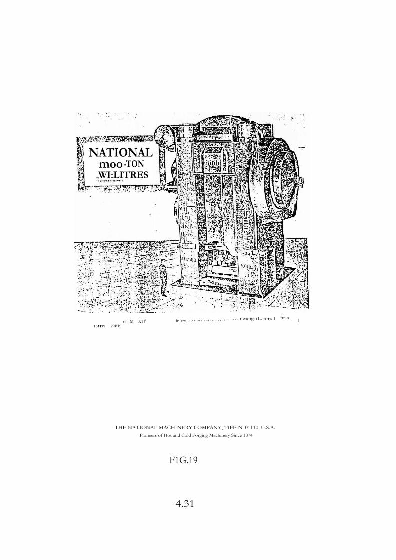
CRANK AND ECCENTRIC PRESSES, KNUCLE-JOINT PRESSES, WEDGE PRESSES AND HORIZONTAL UPSETTERS belong to this category (Ref.Fig.19)
6.3 Load Restricted Machines
The Hydraulic Press is a load restricted machine since the
maximum load can be developed at any position within the available
stroke. Here the load depends upon the oil pressure and the speed or
Ram Travel is proportional to the rate at which oil is supplied to the
cylinder.
7. SOME EXAMPLES OF FORGING PROCESSES
Fig.20 - Shows flow chart
4.29

Counterblow hammers up 1.0 .2500k) blow capacity _ pneumut;c driven
•••
Short stroke (Ile forging hammers hydraulic driven up to 160 kJ. .• 'blow capacity
• • 'Counterbiow hammers up to
• 2500 kJ blow capacity - • pneumatic driven
Counterblow hammers hydrauit driven up 10250 kJ blow capacity,.
• *J4
• ,;
• ! • cf;.,'
Short•strcke dle-lorging hammers pneumatic driven 'tip to 160 kJ. * blow capacity
A
Pneumatic die forging hammers up to 15 kJ blow capacity
Belt drcr hammers up to 50.kJ blow caracIty
- t X' • ...It*: •
r -.4. • - ' •-• i;•
•
- • . '4: •• •• t •
Hammers for cile-fo)ging • -4
and preforming; •
FIG. 18
4.30
NATIONAL moo -TON
_WI:LITRES
tf`i M X11' in.rry :1 ,1113111e •1/.e. ;1111, 1 I111,0 nwang: i1.. titri. I frnin 1 I 31111 /1.0111)
I fif
THE NATIONAL MACHINERY COMPANY, TIFFIN. 01110, U.S.A. Pioneers of Hot and Cold Forging Machinery Since 1874
F1G.19
4.31

Flow Chart component: 1210 Steering -Arm
RAW
MATERIAL
Bender
Press
Billet Cutting
thearIng/Sawing
Scale Break
Pre88
Billet Heating
Furnace
Reduce . Rolling ---- ;.;
Raduce Roll
ti
IL
- Blocker
Press
Finisher
Press
Trimming
Press
Hot Coining
Press
Heat Treatment
Grinding
Shot Blasting
Grinding Machine .
Roloblaat
Hardening and Tempering
M. ENGINE Crack Testing 11.30161TIMENVIIIMIIMMINIIMMOM+
DIVISION Cold Coining
- 1
Pro88 Magna Flux Craok
DetaotIon Maohlne FIG.20
20 4.32

Fig.21 - Shows the manufacturing stages of Steering Arm Forging on a 2000 T Forging Press
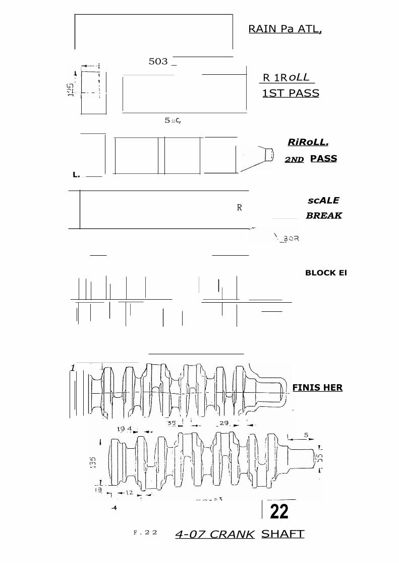
Fig.22 - Shows process sequence of 4 cylinder Crankshaft on 6000 T Forging Press
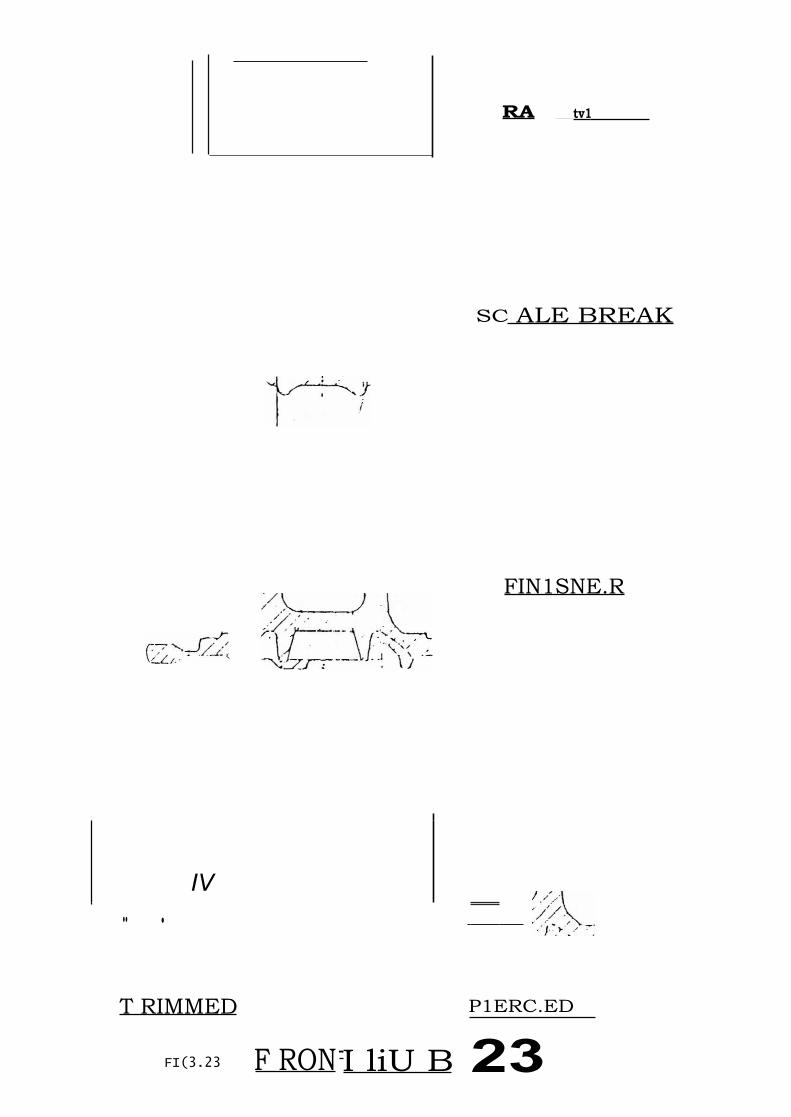
Fig.23 Shows process sequence of Front Hub on 12,000 lb Erie Hammers
Fig.24 - Shows manufacturing sequence of Stub Axle on 12,000 lb Erie Hammers
Fig.25 - Shows the manufacturing sequence of Rear Axle Shaft on 5" upsetter
8. RECENT DEVELOPMENTS IN FORGING
As far as latest developments in forging technology are concerned
these are: Orbital Forging, Cross Rolling, Cold and Warm Extrusion.
Automation of Forging Presses and Hammers also form part of this.
Advances in the field are also taking place in the area of
CAD/CAN where the die development time is considerably reduced.
4.33

- - --- " N•
T Tvl NI E. 1:),.
- 77.<,
I C' \\,‘ ■
-17 • 7
-G. • -
-•-
.4 • _ - •••
- 140T- CO) N E
•
FP.21 4.34

. 20D PASS
I
7
fV7,-
L.
BENDER
FIG.21 (CO NM)
STEERIN G ARM FORG.
1 -
51042.
T RAW MATL
GOO+5
REDO CE ROLLIN
f ST PASS
•• --p.7 at I zoo
-1.10 5
4.35
503 _
5 :L1c,
L.
1
BLOCK El
-4 22
FINIS HER
5
RAIN Pa ATL,
R 1R oLL 1ST PASS
RiRoLL.
2ND PASS
scALE
BREAK R
F . 2 2 4-07 CRANK SHAFT
RA tv1
SC ALE BREAK
FIN1SNE.R
IV
•• •
T RIMMED P1ERC.ED
FI(3.23 F RON -I liU B 23

M 4.4
R AW MAIL . I .4
1
C:)
c)
• - —
S CALE-BREAK
• BLOCKE.R
T RIMMED
FIG.24 401 STUB AXLE
2- LI 4.38

77
RAW MK%
—BLocKER
SK -5
fiNiskiER
S -6
TRIMMED
602 STUB Axt.E.
SK-
S C A LE- BREAK
SK-3
4.39

p6 !1,90.1 5•3
. 1136+2
RAN MAIL
1175
-- -( r _ () SPLINE END UPSETTING
302..
J Si
FL AN GE END- Ls -r PASS
12,6 1
c 0
• NID PA5S FIG.25 2 r),) 25
4.40

LU
Cl
902
3RD PASS
k
- !I) 1 - i-i'
FINAL PASS
25
4.41


