
FN & C-lineSwitch-Disconnectors
About Us
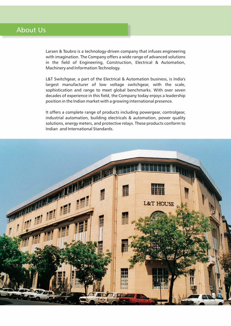
Larsen & Toubro is a technology-driven company that infuses engineering
with imagination. The Company offers a wide range of advanced solutions
in the field of Engineering, Construction, Electrical & Automation,
Machinery and Information Technology.
L&T Switchgear, a part of the Electrical & Automation business, is India's
largest manufacturer of low voltage switchgear, with the scale,
sophistication and range to meet global benchmarks. With over seven
decades of experience in this field, the Company today enjoys a leadership
position in the Indian market with a growing international presence.
It offers a complete range of products including powergear, controlgear,
industrial automation, building electricals & automation, power quality
solutions, energy meters, and protective relays. These products conform to
Indian and International Standards.

Standards & Approvals
Product Range
Product Features
Technical Specifications
Spares and Accessories
Overall Dimensions
Ordering Information
Universal Mounting
1
2
3
7
9
11
13
14
Standards & Approvals
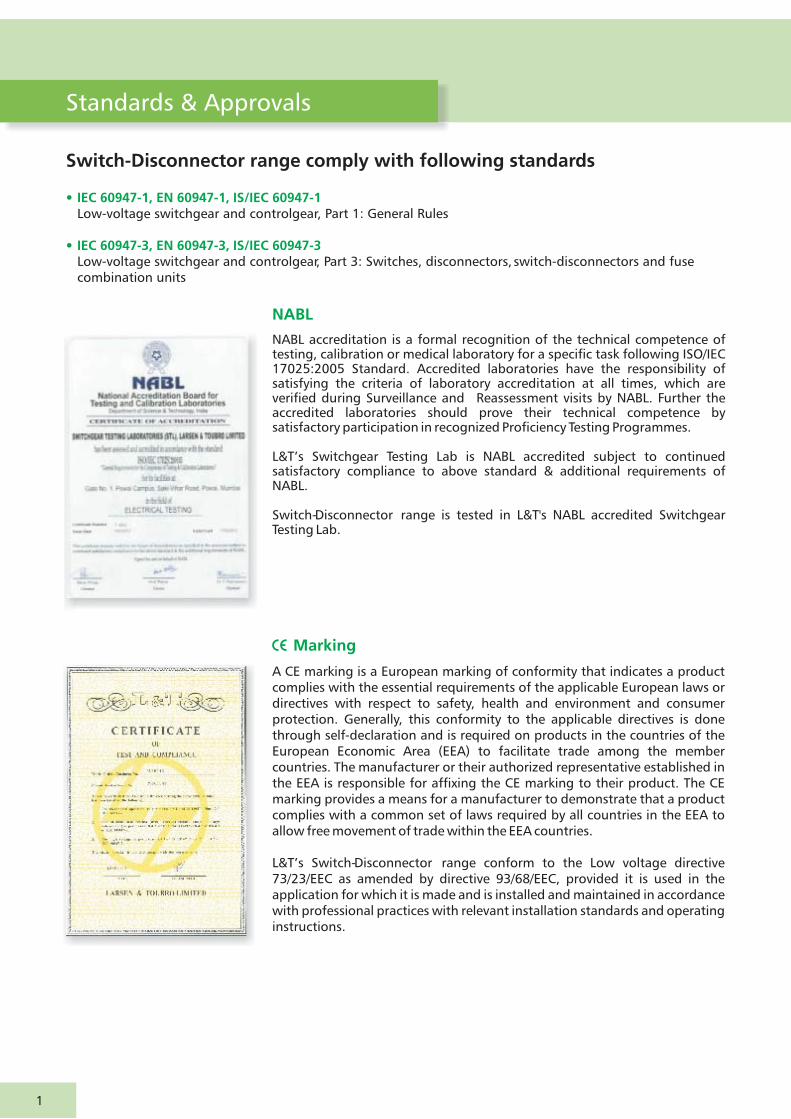
A CE marking is a European marking of conformity that indicates a product complies with the essential requirements of the applicable European laws or directives with respect to safety, health and environment and consumer protection. Generally, this conformity to the applicable directives is done through self-declaration and is required on products in the countries of the European Economic Area (EEA) to facilitate trade among the member countries. The manufacturer or their authorized representative established in the EEA is responsible for affixing the CE marking to their product. The CE marking provides a means for a manufacturer to demonstrate that a product complies with a common set of laws required by all countries in the EEA to allow free movement of trade within the EEA countries.
L&T’s conform to the Low voltage directive 73/23/EEC as amended by directive 93/68/EEC, provided it is used in the application for which it is made and is installed and maintained in accordance with professional practices with relevant installation standards and operating instructions.
Switch-Disconnector range
Marking
NABL accreditation is a formal recognition of the technical competence of testing, calibration or medical laboratory for a specific task following ISO/IEC 17025:2005 Standard. Accredited laboratories have the responsibility of satisfying the criteria of laboratory accreditation at all times, which are verified during Surveillance and Reassessment visits by NABL. Further the accredited laboratories should prove their technical competence by satisfactory participation in recognized Proficiency Testing Programmes.
L&T’s Switchgear Testing Lab is NABL accredited subject to continued satisfactory compliance to above standard & additional requirements of NABL.
Switch- range is tested in L&T's NABL accredited Switchgear Testing Lab.
Disconnector
NABL
Switch-Disconnector range comply with following standards
• IEC 60947-1, EN 60947-1, IS/IEC 60947-1
• IEC 60947-3, EN 60947-3, IS/IEC 60947-3
Low-voltage switchgear and controlgear, Part 1: General Rules
Low-voltage switchgear and controlgear, Part 3: Switches, disconnectors, switch-disconnectors and fuse combination units
1

Product Range
Versions
TPN FN S-D suitable for open execution
The TPN FN S-D range is available from 32 A to 1000 A, suitable for 415/690V AC & 440V DC application.
2P FN S-D suitable for open execution
The 2P FN S-D range is available from 32 A to 1000 A, suitable for 220V DC application.
S-D Range
FN & offers you a unique series of Switch-Disconnector combining compactness with high
performance & Customer convenience.
Range covers ratings from 32 A to 2000 A in 6 frame sizes.
TP & FP S-D suitable for open execution
The 3P & 4P C-line S-D range is available from 1000 A to 2000 A, suitable for 690V AC & 440V DC application.
2
Frame No.
32
100
200
315
630
1000
63
125
250
400
800
1250
Ratings (A)
I
II
III
IV
V
VI
1000
1600
-
-
-
-
Type
FN
2000
-
-
-
-
-

FN S-D Product Features
1. Handle
The FN Switch has a unique operating handle with thefollowing features.• Door interlock for safety of operating personnel when switch
is ‘ON’. The interlock can be defeated if required• Built-in padlocking arrangement to lock the unit in ‘OFF’
position• The handle coupling can take a mismatch or ± 3mm in all
directions• IP54 with extended operating handle
2 . Maximum termination capacity
3. Ground clearance
FN switch range provides generous terminal capacity in its compact size, facilitating aluminium termination.
Higher ground clearance between terminals and mounting base plate ensures adequate clearance even after connecting cables. This eliminates the possibility of phase to ground flash over.
3
2
5
3 6
41

4. Positive ON / OFF indication of S-D
The FN Switch indicates true position of contacts. (By a red pointer)
5. Built-in neutral
The FN TPN Switch consists of an integral neutral, making the units suitable for 3 phase, 4 - wire application. FN 32 / 63 has switched neutral while higher ratings have isolable neutral. (For higher ratings switchable neutral kit is available as an accessory)
6. Contact system
Contact system is QUAD BREAK. There are number of parallel moving contacts per pole per break. Hence, better arc quenching & more electrical life of contacts. Each pole has separate bridge carrying the moving contacts, achieving a high order of inter phase separation & avoiding phase-phase flash over.
FUSE CONTACT
TERMINAL
MOVING CONTACT
DIRECTION OF BRIDGE MOVEMENT
FLAT CURRENT CARRYINGZONE / AREA IN CONTACTSUNAFFECTED BY ARCING
4
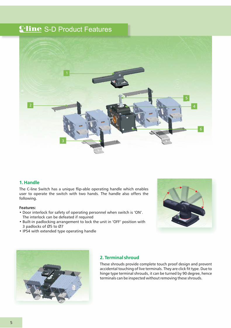
S-D Product Features
1. Handle
The C-line Switch has a unique flip-able operating handle which enables user to operate the switch with two hands. The handle also offers the following.
Features:• Door interlock for safety of operating personnel when switch is ‘ON’.
The interlock can be defeated if required• Built-in padlocking arrangement to lock the unit in ‘OFF’ position with
3 padlocks of Ø5 to Ø7• IP54 with extended type operating handle
2. Terminal shroud
These shrouds provide complete touch proof design and prevent accidental touching of live terminals. They are click fit type. Due to hinge type terminal shrouds, it can be turned by 90 degree, hence terminals can be inspected without removing these shrouds.
2
1
3
6
4
5
5

3. Inter-phase barriers
Inter-phase barriers are provided for additional safety to eliminate possibility of inter-phase short-circuit.
4. Positive ON / OFF indication of S-D
The C-line Switch indicates true position of contacts.
5. Depth adjustable operating shaft
The C-line Switch depth can be varied and fixed as per requirement during installation which is possible due to stepless adjustment of operating shaft.
6. Mechanism and Contact System
Contact system is of double break, knife type having self wiping action with electrodynamic compensation. This ensures reliable performance during normal as well as short circuit fault conditions, offering higher short-time withstand rating.
C-line switch offers high electrical and mechanical life in compact size. The electrical and mechanical life are two times the requirement of the standard.
6

In FN Switch universal mounting is achieved by Type A and Type B handle.
FN S-D operating quadrant chart (Seen from front of the door)
Type A : Supplied as standard with all Switches Type B : Available as an accessory
Universal Mounting
FN & C-line switch range offers a distinctive feature to mount S-D in different quadrants. This feature aids mounting flexibility.
7
Note : Arrow ( ) indicates position of Interlock defeat key
1
0
1
0
OR
OR
OR
OR
B
A
A
B
Sr.No.
1
0
1
0
OR
OR
A
B
3
4
5
6
7
8
1
0
OR
OR
B
A
1
2
Handle (OFF) Position
Operating Quadrant (hand)
SwitchOrientation
DoorCut-out
Handle Type
Coupling
1
0
ON
OFF
ON
OFF
ON
1
0
OFF
ON
OFF
OFF
ON
OFF
ON
OFF
ON
1
0
OFF
ON
8
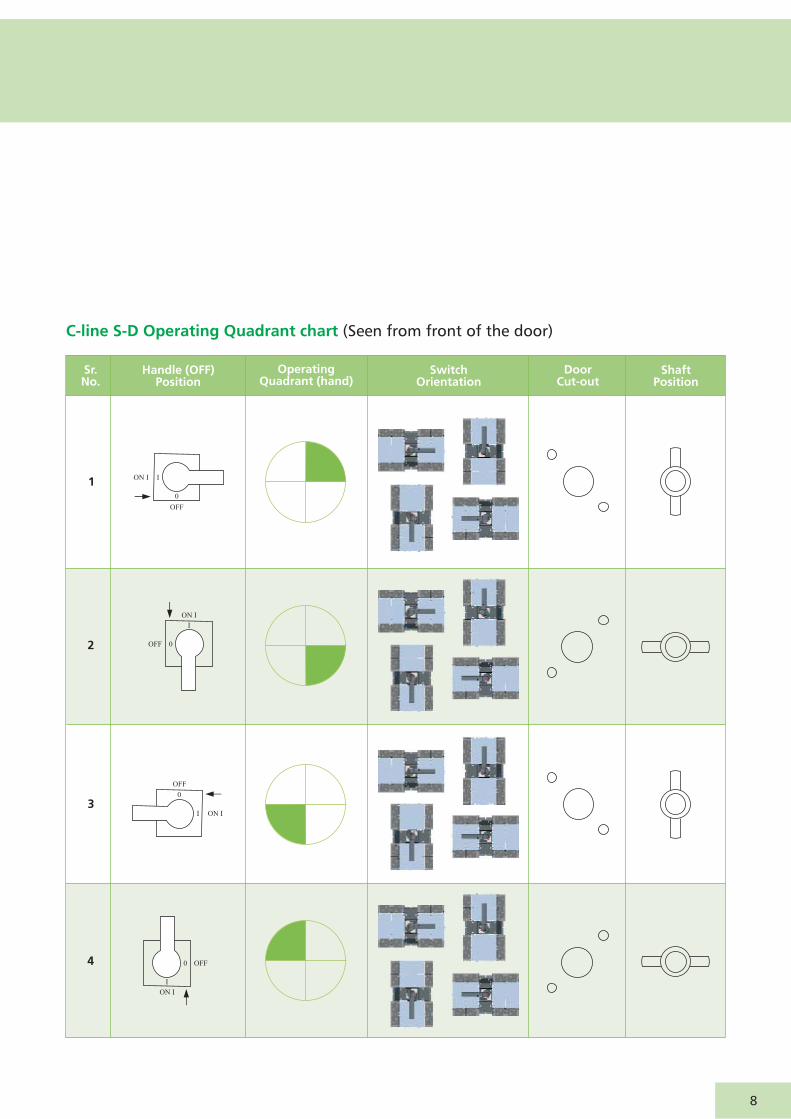
C-line S-D Operating Quadrant chart (Seen from front of the door)
4
Sr.No.
DoorCut-out
Shaft Position
Switch Orientation
Handle (OFF) Position
Operating Quadrant (hand)
0
I
ON I
OFF
3
0
I
ON I
OFF
2
0
I
ON I
OFF
10
ION I
OFF
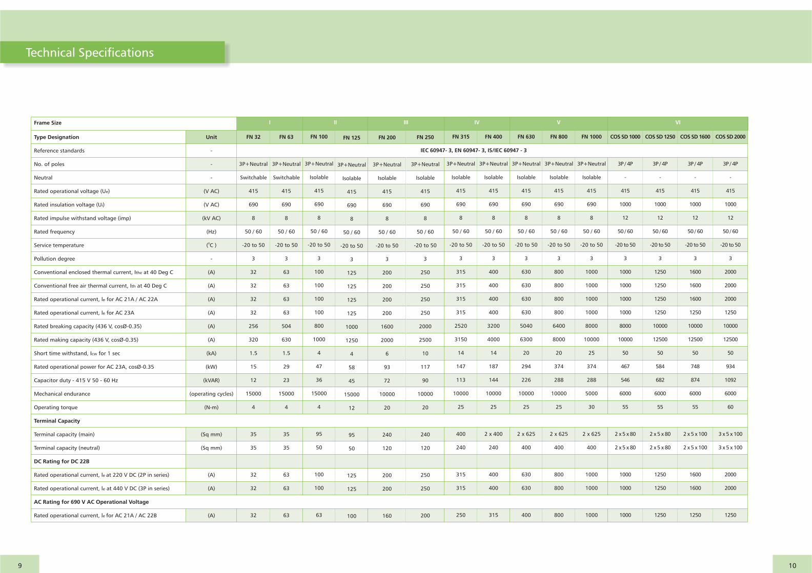
Type Designation
Reference standards
No. of poles
Neutral
Rated operational voltage (Ue)
Rated insulation voltage (Ui)
Rated impulse withstand voltage (imp)
Rated frequency
Service temperature
Pollution degree
Conventional enclosed thermal current, Ithe at 40 Deg C
Conventional free air thermal current, Ith at 40 Deg C
Rated operational current, le for AC 21A / AC 22A
Rated operational current, le for AC 23A
Rated breaking capacity (436 V, cosØ-0.35)
Rated making capacity (436 V, cosØ-0.35)
Short time withstand, Icw for 1 sec
Rated operational power for AC 23A, cosØ-0.35
Capacitor duty - 415 V 50 - 60 Hz
Mechanical endurance
Operating torque
Terminal Capacity
Terminal capacity (main)
Terminal capacity (neutral)
DC Rating for DC 22B
Rated operational current, le at 220 V DC (2P in series)
Rated operational current, le at 440 V DC (3P in series)
AC Rating for 690 V AC Operational Voltage
Rated operational current, le for AC 21A / AC 22B
Unit
-
-
-
(V AC)
(V AC)
(kV AC)
(Hz)
0( C )
-
(A)
(A)
(A)
(A)
(A)
(A)
(kA)
(kW)
(kVAR)
(operating cycles)
(N-m)
(Sq mm)
(Sq mm)
(A)
(A)
(A)
FN 32
3P+Neutral
Switchable
415
690
8
50 / 60
-20 to 50
3
32
32
32
32
256
320
1.5
15
12
15000
4
35
35
32
32
32
FN 100
3P+Neutral
Isolable
415
690
8
50 / 60
-20 to 50
3
100
100
100
100
800
1000
4
47
36
15000
4
95
50
100
100
63
FN 63
3P+Neutral
Switchable
415
690
8
50 / 60
-20 to 50
3
63
63
63
63
504
630
1.5
29
23
15000
4
35
35
63
63
63
FN 125
3P+Neutral
Isolable
415
690
8
50 / 60
-20 to 50
3
125
125
125
125
1000
1250
4
58
45
15000
12
95
50
125
125
100
FN 400
3P+Neutral
Isolable
415
690
8
50 / 60
-20 to 50
3
400
400
400
400
3200
4000
14
187
144
10000
25
400
240
400
400
315
2 x
FN 200
3P+Neutral
Isolable
415
690
8
50 / 60
-20 to 50
3
200
200
200
200
1600
2000
6
93
72
10000
20
240
120
200
200
160
FN 250
3P+Neutral
Isolable
415
690
8
50 / 60
-20 to 50
3
250
250
250
250
2000
2500
10
117
90
10000
20
240
120
250
250
200
FN 315
3P+Neutral
Isolable
415
690
8
50 / 60
-20 to 50
3
315
315
315
315
2520
3150
14
147
113
10000
25
400
240
315
315
250
FN 630
3P+Neutral
Isolable
415
690
8
50 / 60
-20 to 50
3
630
630
630
630
5040
6300
20
294
226
10000
25
2 x 625
400
630
630
400
FN 800
3P+Neutral
Isolable
415
690
8
50 / 60
-20 to 50
3
800
800
800
800
6400
8000
20
374
288
10000
25
2 x 625
400
800
800
800
FN 1000
3P+Neutral
Isolable
415
690
8
50 / 60
-20 to 50
3
1000
1000
1000
1000
8000
10000
25
374
288
5000
30
2 x 625
400
1000
1000
1000
COS SD 1000
3P / 4P
-
415
1000
12
50 / 60
-20 to 50
3
1000
1000
1000
1000
8000
10000
50
467
546
6000
55
2 x 5 x 80
1000
1000
1000
2 x 5 x 80
COS SD 1250
3P / 4P
-
415
1000
12
50 / 60
-20 to 50
3
1250
1250
1250
1250
10000
12500
50
584
682
6000
55
2 x 5 x 80
1250
1250
1250
2 x 5 x 80
COS SD 1600
3P / 4P
-
415
1000
12
50 / 60
-20 to 50
3
1600
1600
1600
1250
10000
12500
50
748
874
6000
55
2 x 5 x 100
1600
1600
1250
2 x 5 x 100
COS SD 2000
3P / 4P
-
415
1000
12
50 / 60
-20 to 50
3
2000
2000
2000
1250
10000
12500
50
934
1092
6000
60
3 x 5 x 100
2000
2000
1250
3 x 5 x 100
IEC 60947- 3, EN 60947- 3, IS/IEC 60947 - 3
Frame Size I II III IV V VI
9 10
Technical Specifications
Spares and Accessories
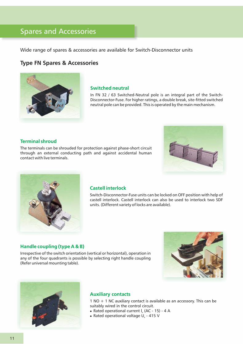
Auxiliary contacts
1 NO + 1 NC auxiliary contact is available as an accessory. This can be suitably wired in the control circuit. �Rated operational current l (AC - 15) - 4 A�Rated operational voltage U - 415 V e
e
Switched neutral
In FN 32 / 63 Switched-Neutral pole is an integral part of the Switch-Disconnector-Fuse. For higher ratings, a double break, site-fitted switched neutral pole can be provided. This is operated by the main mechanism.
Wide range of spares & accessories are available for Switch-Disconnector units
Type FN Spares & Accessories
Terminal shroud
The terminals can be shrouded for protection against phase-short circuit through an external conducting path and against accidental human contact with live terminals.
Castell interlock
Switch-Disconnector-Fuse units can be locked on OFF position with help of castell interlock. Castell interlock can also be used to interlock two SDF units. (Different variety of locks are available).
Handle coupling (type A & B)
Irrespective of the switch orientation (vertical or horizontal), operation in any of the four quadrants is possible by selecting right handle coupling (Refer universal mounting table).
11
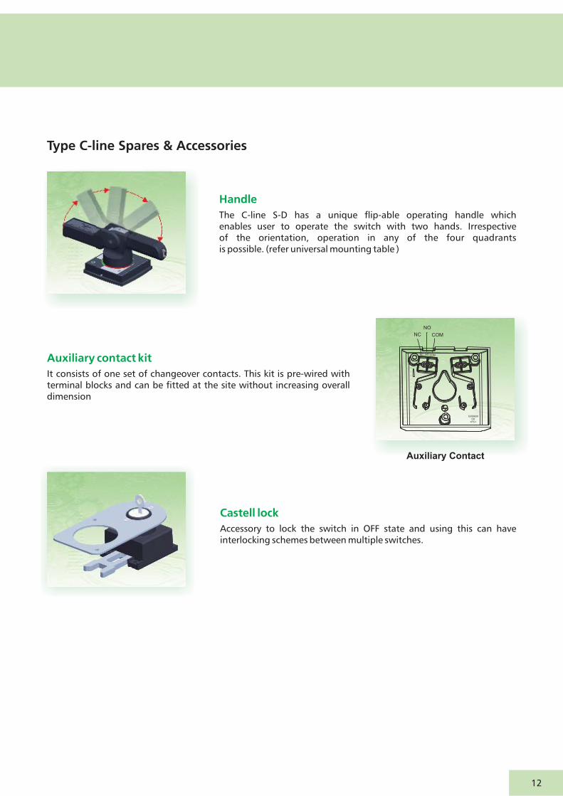
Type C-line Spares & Accessories
Handle
The C-line S-D has a unique flip-able operating handle which enables user to operate the switch with two hands. Irrespective of the orientation, operation in any of the four quadrants is possible. (refer universal mounting table )
Auxiliary contact kit
It consists of one set of changeover contacts. This kit is pre-wired with terminal blocks and can be fitted at the site without increasing overall dimension
Castell lock
Accessory to lock the switch in OFF state and using this can have interlocking schemes between multiple switches.
12
NO
NC COM
COMNONC
Ck50609101
>PC<
Auxiliary Contact
Note : All dimensions are in mm.
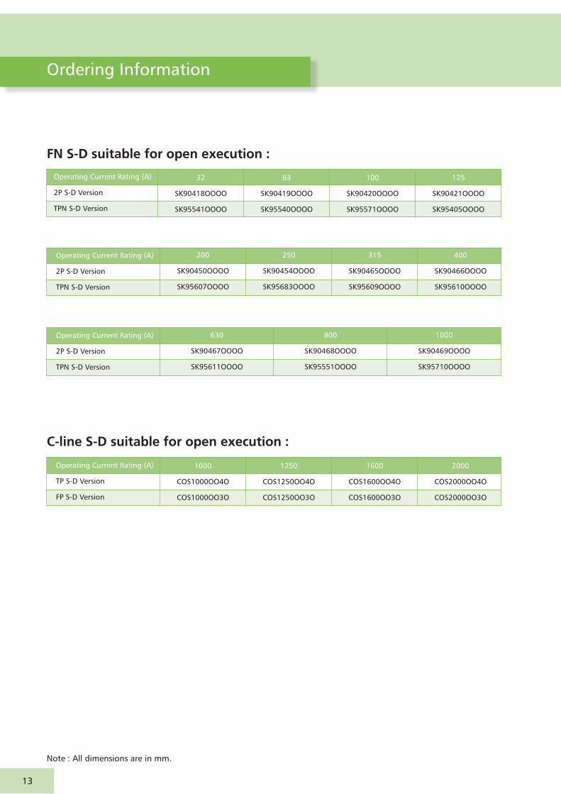
Ordering Information
13
FN S-D suitable for open execution :
Operating Current Rating (A)
TP S-D Version
FP S-D Version
1000
COS1000OO4O
COS1000OO3O
1250
COS1250OO4O
COS1250OO3O
1600
COS1600OO4O
COS1600OO3O
2000
COS2000OO4O
COS2000OO3O
C-line S-D suitable for open execution :
Operating Current Rating (A)
2P S-D Version
TPN S-D Version
315
SK90465OOOO
SK95609OOOO
400
SK90466OOOO
SK95610OOOO
200
SK90450OOOO
SK95607OOOO
250
SK90454OOOO
SK95683OOOO
Operating Current Rating (A)
2P S-D Version
TPN S-D Version
32
SK90418OOOO
SK95541OOOO
63
SK90419OOOO
SK95540OOOO
100
SK90420OOOO
SK95571OOOO
125
SK90421OOOO
SK95405OOOO
Operating Current Rating (A)
2P S-D Version
TPN S-D Version
630
SK90467OOOO
SK95611OOOO
800
SK90468OOOO
SK95551OOOO
1000
SK90469OOOO
SK95710OOOO

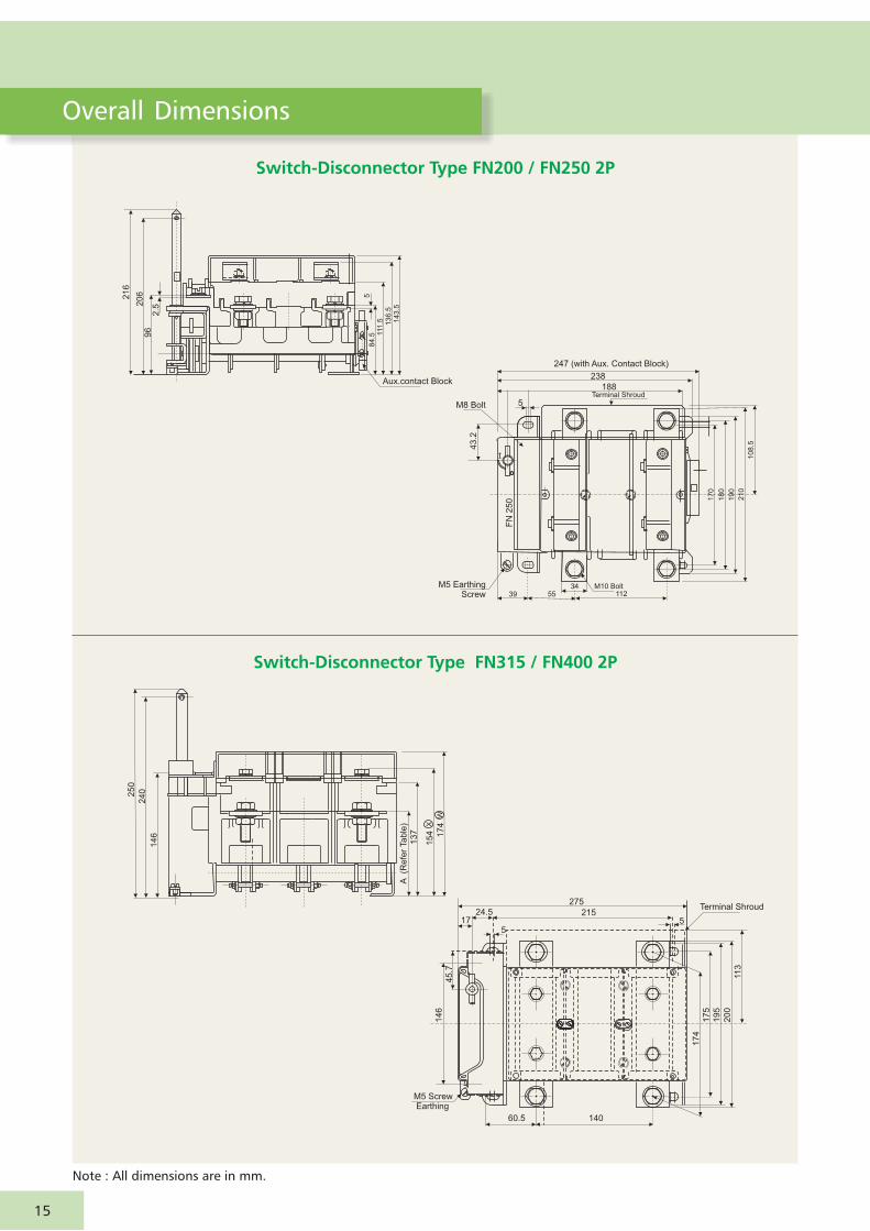
Overall Dimensions
Note : All dimensions are in mm.
Switch-Disconnector Type FN32 / FN63 2P
6 SQ
5
15
0
35
63
83
.5
113.229.6
555
2 Mounting HolesFor M4 Screws
95
75
31 44.1
16
54
44.5
79
Te
rmin
al S
hro
ud
(optional A
ccessory
)
Aux.contact Block
69 94 12
93
18
0
17
0
77.6
204
160
20Ø9
84
13
6
15
4
944839.6
12
5
75
26
7
12 22
5
12
M5 ScrewEarthing
12
2
Switch-Disconnector 100 / FN125 Type FN 2P
14
Note : All dimensions are in mm.
Overall Dimensions
Switch-Disconnector 200 / FN250 Type FN 2P
Switch-Disconnector FN315 / FN400 Type 2P
21
6
20
6
2.5
96
584.5 1
11.5 136.5
143.5
Aux.contact Block
247 (with Aux. Contact Block)
238
188Terminal Shroud
M8 Bolt
43.2
M5 EarthingScrew 39 55
34112
M10 Bolt
FN
250
5
60.5 140
17
41
75
19
5
20
0
11
3
517
45
.71
46
M5 Screw Earthing
Terminal Shroud275
21524.5
A (R
efe
r Ta
ble
)1
37
15
4 17
4X
W
25
0
24
0
14
6
17
0
18
0
19
0
21
0
10
8.5
5
15
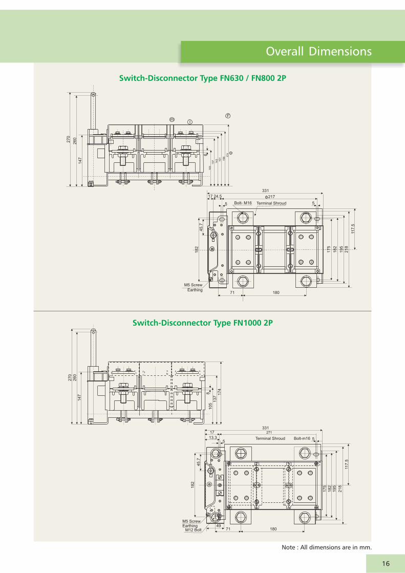
Note : All dimensions are in mm.
Overall Dimensions
Switch-Disconnector FN630 / FN800 Type 2P
mI
G
174
156
15
1
143
137
103
6
14
7
26
0
27
0
F
+ + + +
++++
17 24.5
545.7
18
2
M5 Screw
Earthing71 180
21
8
19
5
18
2
17
5
11
7.5
5Bolt- M16 Terminal Shroud
B 217
331
Switch-Disconnector FN1000 Type 2P
17
41
37
10
58
27
02
60
14
7
13.35
331271
Terminal Shroud Bolt-m16
17
45.7
18
2
21
8
19
51
82
17
5
11
7.5
1807149
M5 ScrewEarthing
M12 Bolt
5
16

Note : All dimensions are in mm.
Overall Dimensions
6 SQ
5
15
0
35
63
83.5
113.229.65
55
2 Mounting HolesFor M4 Screws
95
75
31 15.1 29
16
27 27
44
.5
79
Te
rmin
al S
hro
ud
(op
tio
na
l Acce
sso
ry)
Aux.contact Block
69 94 12
93
18
0
17
0
2
77.6
204
160
20 Ø9
84
13
6
15
4
47 474839.6
20
12
5
75
26
7
12 22
5
12
M6 Screw
M5 ScrewEarthing
12
2
Switch-Disconnector Type FN32 / 63 TPNFN
Switch-Disconnector 100 / FN125 Type FN TPN
17

Switch-Disconnector 200 / FN250 Type FN TPN
21
62
06
2.5
96
584.5 1
11
.5 13
6.5
14
3.5
Aux.contact Block
247 (with Aux. Contact Block)
238
188Terminal Shroud
M8 Bolt
43.2
M5 Earthing
Screw29
39 5534
58 56M10 Bolt
FN
250
5
60.5 70 7040
17
41
75
19
52
00
11
3
Y Bolt - B (Refer Table) 517 16.3
45.7
14
6
M5 Screw Earthing
M10 Bolt 43
Terminal Shroud275
21524.5
A (
Re
fer
Ta
ble
)1
37
15
4X
17
4W
A1B1
3
25
02
40
14
6
17
0
18
01
90
21
0108.5
10
9
Switch-Disconnector FN315 / FN400 Type TPN
5
Overall Dimensions
Note : All dimensions are in mm.
18

mI
G
17
4
15
61
51
14
31
37
10
36
14
74
26
0
27
0
Switch-Disconnector FN630 / FN800 Type TPN
17
41
37
10
58
27
02
60
14
7
4
13.35
331
271
Terminal Shroud Bolt-m16
17
45.7
18
2 21
8
19
5
18
2
17
5
11
7.5
9060
907149
M5 ScrewEarthing
M12 Bolt
Switch-Disconnector FN1000 Type TPN
Overall Dimensions
Note : All dimensions are in mm.
19
+ + + +
++++++
+ +
17 24.5
13.3
5
45.7
18
2
M5 Screw
Earthing
M 12 Bolt
4971 90
6090
21
8
19
5
18
21
75
11
7.5
5Bolt- M16Terminal Shroud
B 217
331
5

Overall Dimensions
Note : All dimensions are in mm.
Switch-Disconnector Type COS2000 3P
Switch-Disconnector Type COS1000/COS1250/COS1600A 3P
103
212.5 (mounting)
105212.5
32
.5
4 Nos. Mounting Holes
Suitable for M10 Screws
434.5
20
0 (
mo
un
tin
g)
A
36
5 (
with
Acce
sso
rie
s)
26.5
8.5
M5 Hardware For Earthing
LUG (25 sq.mm)
B
Panel Door
C
D
15
1 20
5
Maxim
um
:312
Min
imu
m:2
62
A
310
310
330
B
8
8
12
C
56
56
54
Rating
1000
1250
1600
Cat No.
COS1000OO3O
COS1250OO3O
COS1600OO3O
D
87
87
85
212.5 (Mounting)
192.5
434.5
125
32.5
103
42
0
465 (
With A
ccessories)
26
5 (
Mo
un
tin
g)
4 Nos. Mounting Holes
Suitable For M10 Screws
26.5
8.5
M5 Hardware for Earthing
Lug (25 Sq.mm)
15
Panel Door
52.5
Ma
xim
um
:31
2
Min
imu
m:2
62
83.5
15
1 20
5
20
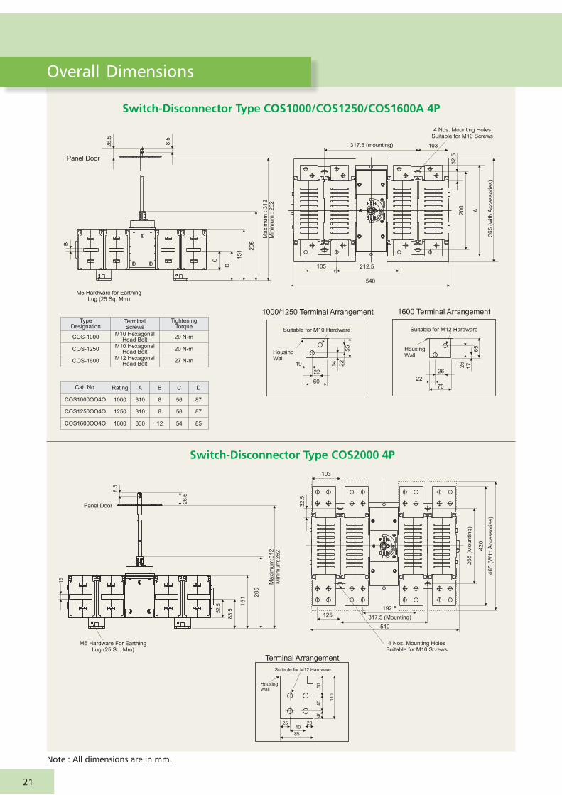
Note : All dimensions are in mm.
Switch-Disconnector Type COS 1000/COS1250/COS1600A 4P
A
310
310
330
B
8
8
12
C
56
56
54
Rating
1000
1250
1600
Cat. No.
COS1000OO4O
COS1250OO4O
COS1600OO4O
D
87
87
85
4 Nos. Mounting Holes Suitable for M10 Screws
317.5 (mounting) 103
105
540
212.5
32.5
20
0
A
36
5 (
with
Acce
sso
rie
s)
M5 Hardware for EarthingLug (25 Sq. Mm)
B
D
15
1 20
5
Maxim
um
: 3
12
Min
imum
: 2
62
C
Panel Door
26.5
8.5
19
22
14 22
55
60
26
26
17
65
22
70
1000/1250 Terminal Arrangement 1600 Terminal Arrangement
Suitable for M12 HardwareSuitable for M10 Hardware
Housing Wall
Housing Wall
Type Designation
TerminalScrews
Tightening Torque
COS-1000
COS-1250
COS-1600
M10 HexagonalHead Bolt
M10 HexagonalHead Bolt
M12 HexagonalHead Bolt
20 N-m
20 N-m
27 N-m
Switch-Disconnector Type COS2000 4P
15
Panel Door
52
.5
83.5
15
1 20
5
125192.5
540
42
0
465 (
With A
ccessories)
26
5 (
Mo
un
tin
g)
317.5 (Mounting)
4 Nos. Mounting HolesSuitable for M10 Screws
26
.5
8.5
M5 Hardware For Earthing Lug (25 Sq. Mm)
Ma
xim
um
:31
2M
inim
um
:26
2
103
32.5
50
40
40
110
85
4025 20
Terminal Arrangement
Suitable for M12 Hardware
Housing Wall
21
Overall Dimensions

Note : All dimensions are in mm.
Overall Dimensions
Termination Arrangement
Recommended spacer thickness is the busbar thickness used
Minimum interphase clearance of 25mm is recommended for busbars
Minimum ground clearance of 19 mm is recommended
Recommended Termination Practices for Busbar Width60-80mm With Diagonal Hole Configuration
Busbar Sizes as Per Standard ( Table 2 ) :
BusbarConfiguartion 1
(1+1)
BusbarConfiguartion 3
(2+2)
BusbarConfiguartion 4
(2+3)
BusbarConfiguartion 2
(1+2)
*For Aluminium termination as per standard.1250A:Factory fitted hardware used.1600/2000A:Bolt length of 85mm used.
Terminal
Spacer
Busbar
TABLE 1
Refer Table 1.Refer Table 1.
A
B B
A
Note : 1. Different configurations of busbars can be used maintaining minimum cross section areas as specified in the table 2. 2. Factory supplied bolt length caters to the copper bus bar termination as per standard in case of different configurations & cross sectional areas. Bolt of higher length may be required.
CK50604101
FR<
Max Space for Bus Bar (mm)
Max Space for Bus Bar (mm)
1000/1250 A
25
31
1600 A
22
30
2000 A
20
48
A
B
1250 A
80 x 5 x 2Nos
63 x 12 x 2Nos
1000 A
60 x 5 x 2Nos
50 x 10 x 2Nos
Busbar
Cu
* Al
1600 A
100 x 5 x 2Nos
50 x 8 x 4Nos
2000 A
100 x 5 x 3Nos
100 x 10 x 3Nos
Termination of 100 mm Bus Bar
92.5 2525
1000 / 1250 / 1600 A
92.525 25
2000 A
Busbar Dimensions for 1600A 20 20
60 60
27 27
Direct Termination of 100 mm Bus BarPossible in Case of 2000 A.
22
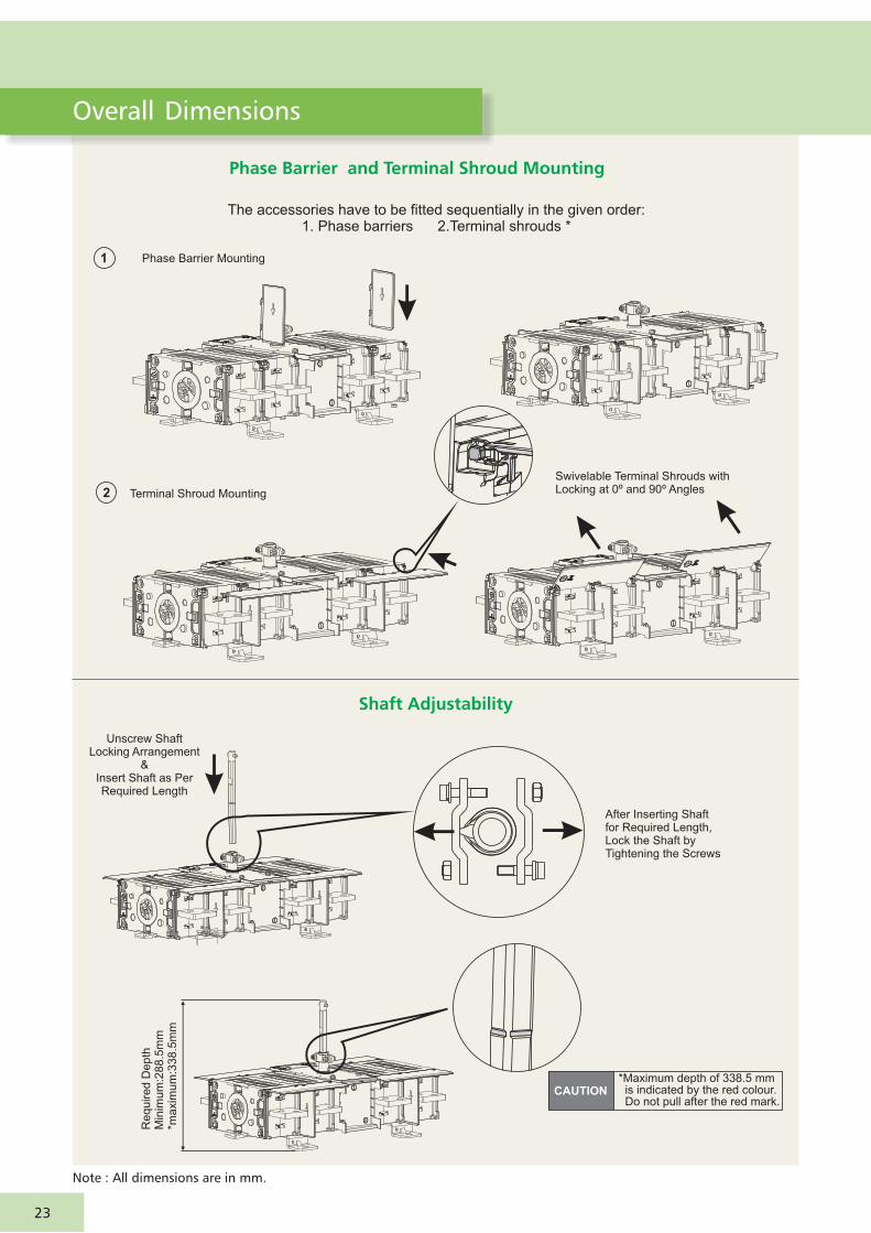
Phase Barrier and Terminal Shroud Mounting
The accessories have to be fitted sequentially in the given order:1. Phase barriers 2.Terminal shrouds *
2
1
Swivelable Terminal Shrouds withLocking at 0º and 90º Angles
Phase Barrier Mounting
Terminal Shroud Mounting
Shaft Adjustability
After Inserting Shaftfor Required Length, Lock the Shaft byTightening the Screws
Unscrew ShaftLocking Arrangement
&Insert Shaft as PerRequired Length
*Maximum depth of 338.5 mm is indicated by the red colour. Do not pull after the red mark.
Re
qu
ire
d D
ep
thM
inim
um
:28
8.5
mm
*ma
xim
um
:33
8.5
mm
Note : All dimensions are in mm.
23
CAUTION
Overall Dimensions
Note : All dimensions are in mm.
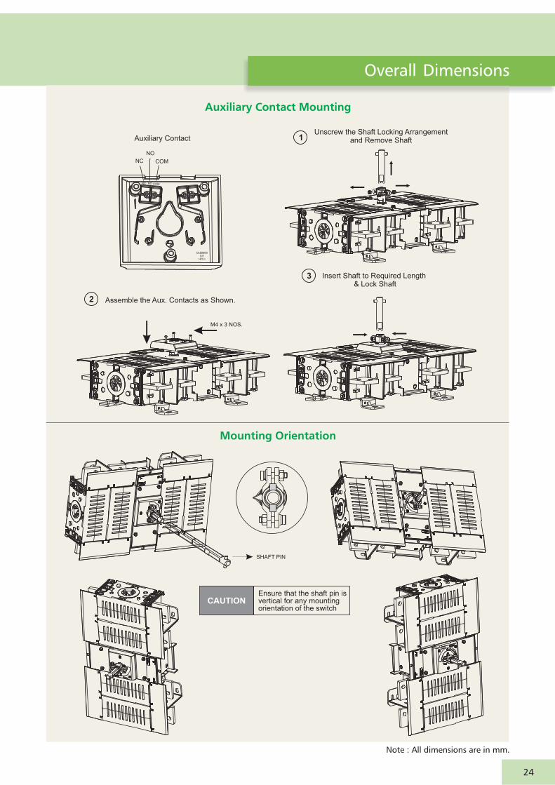
Auxiliary Contact Mounting
Mounting Orientation
Ensure that the shaft pin is vertical for any mounting orientation of the switch
SHAFT PIN
Auxiliary Contact
NO
NC COM
Unscrew the Shaft Locking Arrangementand Remove Shaft 1
M4 x 3 NOS.
Assemble the Aux. Contacts as Shown.2
Insert Shaft to Required Length & Lock Shaft
3
COMNONC
Ck50609101
>PC<
24
Overall Dimensions
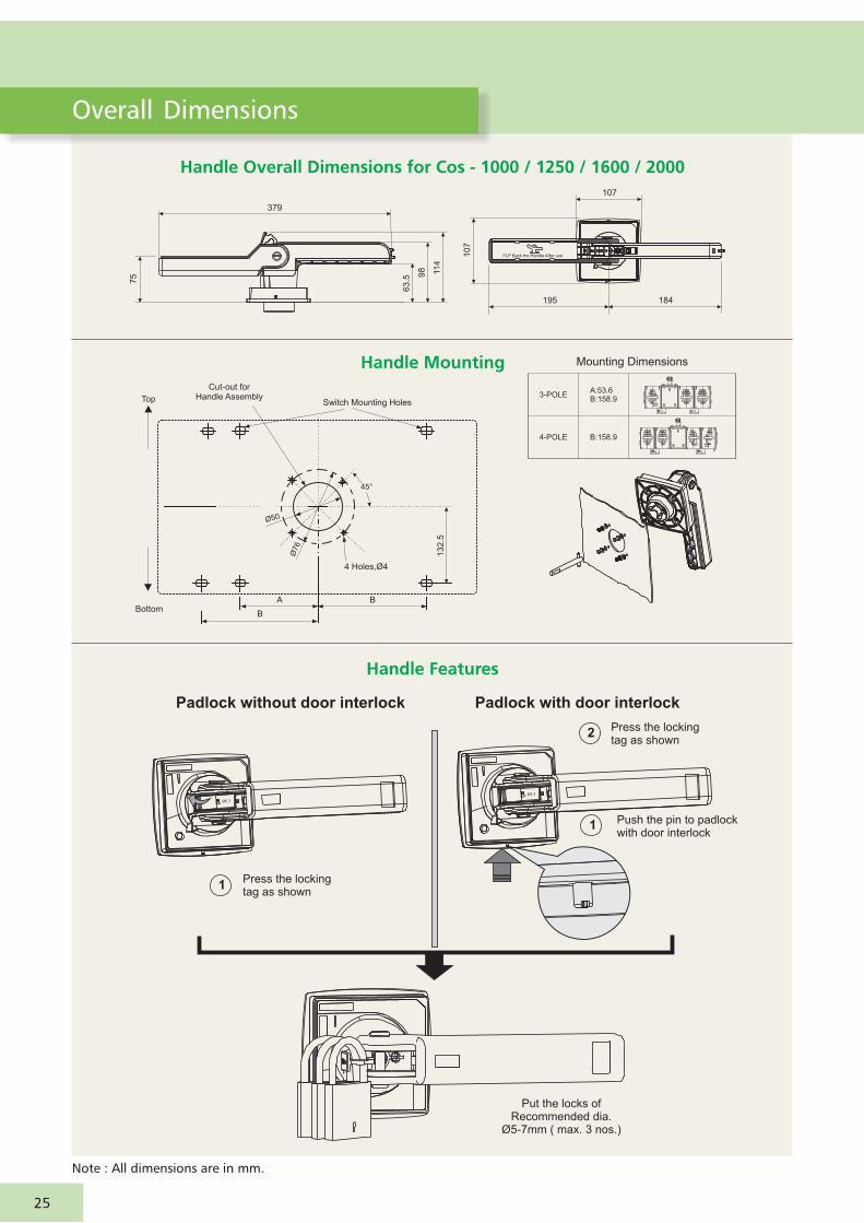
Handle Overall Dimensions for Cos - 1000 / 1250 / 1600 / 2000
Handle Mounting
75
63.5
98 11
4
379
10
7
195
107
184
Cut-out forHandle Assembly
BA
B
13
2.5
4 Holes,Ø4
Ø6
7
50Ø
45°
Switch Mounting HolesTop
Bottom
Mounting Dimensions
3-POLE
4-POLE
A:53.6B:158.9
B:158.9
FLP Back the Handle After use
Handle Features
Padlock without door interlock Padlock with door interlock
1Press the lockingtag as shown
Put the locks ofRecommended dia.
Ø5-7mm ( max. 3 nos.)
2 Press the lockingtag as shown
1 Push the pin to padlockwith door interlock
Ø5.7
Ø5.7
Note : All dimensions are in mm.
Overall Dimensions
25

Handle Features
Handle Flipping
Defeat In ‘on’ State
Enclosureor panel
Panel door
Switch
AUTO RESTORATION
1 Push to open,flip handle
1Push the defeatbutton with apin to defeat
2 Open the door3
Push the door Ensure the same orientationof shaft and handle coupler
2 Flip back the handle after use
FLP Back the Handle After Use
Ø5.7
Ø5
.7
Ø5
.7
Ø5
.7
Ø5.7
Note : All dimensions are in mm.
26
Overall Dimensions

Notes:

Notes:

SP 01955 R1 (INT)
Khairasol, Degaul AvenueDurgapur 713 212Tel: 0343-2540448 / 2540449 / 2540443Fax: 0343-2540442e-mail: [email protected]
5, Milanpur Road, Bamuni MaidanGuwahati 781 021Tel: +91 8876554410 / 8876554417Fax: 361-2551308e-mail: [email protected]
II Floor, Vasantha Chambers5-10-173, Fateh Maidan RoadHyderabad 500 004Tel: 040-67015052Fax: 040-23296468e-mail: [email protected]
Monarch Building, 1st FloorD-236 & 237, Amrapali MargVaishali NagarJaipur 302 021Tel: 0141-4385914 to 18Fax: 0141-4385925e-mail: [email protected]
Akashdeep Plaza, 2nd FloorP. O. GolmuriJamshedpur 831 003JharkhandTel: 0657-2312205 / 38Fax: 0657-2341250e-mail: [email protected]
Skybright Bldg; M. G. RoadRavipuram Junction, ErnakulamKochi 682 016Tel: 0484-4409420 / 4 / 5 / 7Fax: 0484-4409426e-mail: [email protected]
3-B, Shakespeare SaraniKolkata 700 071Tel: 033-42005982Fax: 033-22821025 / 7587e-mail: [email protected]
A28, Indira Nagar, Faizabad Road Lucknow 226 016Tel: 0522-4929905 / 04Fax: 0522-2311671e-mail: [email protected]
No: 73, Karpaga Nagar, 8th StreetK. PudurMadurai 625 007Tel: 0452-2537404 / 2521068Fax: 0452-2537552e-mail: [email protected]
Product improvement is a continuous process. For the latest information and special applications, please contact any of our offices listed here.
Electrical Standard Products (ESP) Offices:
HEAD OFFICEL&T Business Park,Tower 'B' / 3rd FloorSaki Vihar Road, PowaiMumbai 400 072Tel: 022-67053229 Fax: 022-67051112e-mail: [email protected]
BRANCH OFFICES501, Sakar Complex I Opp. Gandhigram Rly. Station Ashram RoadAhmedabad 380 009Tel: 079-66304006-11Fax: 079-66304025e-mail: [email protected]
38, Cubbon Road, P. O. Box 5098Bengaluru 560 001Tel: 080-25020100 / 25020324Fax: 080-25580525e-mail: [email protected]
131/1, Zone IIMaharana Pratap NagarBhopal 462 011Tel: 0755-3080511 / 05 / 08 / 13 / 17 / 19 Fax: 0755-3080502e-mail: [email protected]
Plot No. 559, Annapurna ComplexLewis RoadBhubaneswar 751 014Tel: 0674-6451342 / 2436690 / 2436696Fax: 0674-2537309e-mail: [email protected]
Aspire Towers, 4th FloorPlot No. 55, Phase-IIndustrial & Business ParkChandigarh-160 002Tel: 0172-4646840 / 41 / 42 / 46 / 53Fax: 0172-4646802Email: [email protected]
L&T Construction CampusTC-1 Building, II FloorMount-Poonamallee RoadManapakkamChennai 600 089Tel: 044-2270 6800Fax: 044-22706940e-mail: [email protected]
67, Appuswamy RoadPost Bag 7156 Opp. Nirmala CollegeCoimbatore 641 045Tel: 0422-2588120 / 1 / 5Fax: 0422-2588148e-mail: [email protected]
L&T Business Park,Tower 'B' / 5th FloorSaki Vihar Road, PowaiMumbai 400 072Tel: 022-67052874 / 2737 / 1156Fax: 022-67051112e-mail: [email protected]
12, Shivaji NagarNorth Ambajhari RoadNagpur 440 010Tel: 0712-2260012 / 6606421Fax: 2260030 / 6606434e-mail: [email protected]
32, Shivaji Marg P. O. Box 6223New Delhi 110 015Tel: 011-41419514 / 5 / 6Fax: 011-41419600e-mail: [email protected]
L&T House P. O. Box 119 191/1, Dhole Patil RoadPune 411 001Tel: 020-66033395 / 66033279Fax: 020-26164048 / 26164910e-mail: [email protected]
Crystal Tower, 4th Floor, G. E. RoadTelibandhaRaipur - 492 006Tel: 0771-4283214e-mail: [email protected]
3rd Floor Vishwakarma ChambersMajura Gate, Ring RoadSurat 395 002Tel: 0261-2473726Fax: 0261-2477078e-mail: [email protected]
Radhadaya ComplexOld Padra RoadNear Charotar SocietyVadodara 390 007Tel: 0265-6613610 / 1 / 2Fax: 0265-2336184e-mail: [email protected]
Door No. 49-38-14/3/2, 1st floor,NGGO's Colony, Akkayyapalem,Visakhapatnam - 530 016Tel: 0891-2791126 / 2711125Fax: 0891-2791100Email: [email protected]
Larsen & Toubro Limited, Electrical Standard Products
Powai Campus, Mumbai 400 072
Customer Interaction Center (CIC)
BSNL / MTNL (toll free) : 1800 233 5858 Reliance (toll free) : 1800 200 5858
Tel : 022 6774 5858, Fax : 022 6774 5859
E-mail : [email protected] / Website www.Lntebg.com
Registered Office: L&T House, N. M. Marg, Ballard Estate, Mumbai 400 001, INDIA CIN: L99999MH1946PLC004768


