
1
FLORIDA GOVERNMENT UTILITY AUTHORITY
PASCO COUNTY LIFT STATION REHABILITATION
FGUA PROJECT NO. PSP07, PAP07, LIP07, CSP07
(KIMLEY-HORN PROJECT NO. 149723000)
ADDENDUM NO. 2
This addendum is hereby incorporated into the bid documents of the project referenced above. The
following items are clarifications, corrections, additions, deletions and/or revisions to and shall take
precedence over the original documents.
Contract Drawings:
1. Delete Detail 50 from Sheet Number 025. Refer revised drawing E-3 issued as part of this addendum
for clarifications to control panel elevation detail.
2. Delete Detail 51 from Sheet Number 025. Refer revised drawing E-3 issued as part of this addendum
for revised duplex wiring diagram detail.
3. Delete drawings E-2 and E-3 and Insert revised drawings E-2 and E-3 attached issued as part of this
addendum.
Specifications:
1. Delete specification section 16050, 2.6 in its entirety and Insert the following in its place:
“2.6 LIFT STATION CONTROL PANEL
A. General
1. This section specifies the electrical power and control system requirements
for wastewater pump stations. These requirements apply to duplex pump
panels. Similar requirements shall apply when more than two (2) pumps are
involved except for the quantity of control equipment and panel size shall be
increased accordingly. The manufacturer of the control panel shall provide
data to indicate that the manufacturer has a minimum of three (3) years
experience in the building of lift station control panels. The Lift Station Control
Panel (LSCP) manufacturer shall be one of the following:
Unitron Controls.
Sanders Company
Xylem
Primex Controls
B. Lift Station Control Panel Components
One aluminum enclosure.

2
One aluminum or Plexiglas inner safety door.
One main circuit breaker.
One emergency circuit breaker.
Two motor circuit breakers.
Control circuit breaker - 15 amp.
One solid state modular plug-in control unit.
Two FVNR NEMA motor starters with 110V holding coils.
Six overload heaters.
Two overload reset buttons.
*Two H-0-A selector switches.
*One alternator relay.
One phase monitor.
One surge protection device.
One ground lug.
*Four 24V power relays.
One 24V power transformer.
One neutral block.
One generator power receptacle (Appleton Power Tite Catalog No. ADR-1034).
*Six momentary push button switches with indicator lights for float simulation
and seal failure simulation.
One receptacle circuit breaker - 15 amp minimum.
One convenience receptacle, GFI, 110V.
One audible alarm (Edwards Catalog No. 876-N5).
One visual alarm (Ohio Electric Control, Inc., Model RL-3K).
15-amp, 120-volt circuit breakers as required by Sheet E-2
*Indicates items normally incorporated into modular control unit.
NOTE: Integral plug-in control circuitry such as ELCOTEC MODEL 60-12, STACON
MODEL 010-120-122DC, or approved equivalent will be used to incorporate the above
listed items as applicable.
All circuit breakers, modular control unit, and overload resets mounted for operation
through the inner door; elapsed time meters and convenience receptacle mounted on the
inner door.
C. Operation: The function of the control circuit provides for alternating operation of the lead
pump under normal conditions. Should the incoming flow exceed the pumping capacity of
the lead pump, the lag pump shall automatically be activated, and both pumps shall operate
simultaneously until disengaged by float No. 1. In the event of a malfunction or an
incoming flow that exceeds the pumping capacity of both pumps, an audible alarm and
visual light shall be energized to indicate alarm conditions. A silencing switch shall
discontinue the audible alarm, but the alarm light shall remain activated until the high level
condition is corrected.
If one pump should fail for any reason, the second pump shall be activated at the "lag-
pump-on" elevation. If the “turn-off” level control should fail for any reason, the control
circuit shall have the capability of starting the pumps and keeping the station in operation.
In addition, a light shall give visual indication of the regulator failure.

3
D. Lift Station Control Panel Components/Features:
1. Aluminum Enclosure: Enclosure shall be NEMA 4X with minimum dimensions
of 36” width X 36” depth X 12” deep, aluminum, by Hoffman or approved
equivalent, heavy-duty padlock hasp.
2. Inner Safety Door: Panel shall include one aluminum inner safety door, 12 gauge
nominal thickness (minimum) with 3/4-inch, 90 degree break bend on all edges for
rigidity or 1/4-inch gray-smoked Plexiglas; full length aluminum hinge; positive
twist lock handle; safety latch to keep door open during maintenance.
3. Main and Emergency Breaker: The panel shall include circuit breakers sized as
required for main power and emergency power disconnect. Shall be mounted on
the subpanel with handles through inner door and shall include a mechanical
interlock on the handles to ensure that only one breaker can be in the "ON" position
at any one time. Panel shall also include an externally mounted generator power
receptacle prewired to the emergency breaker.
4. High Level Alarm System: The panel shall include a vapor proof red light mounted
on top of the enclosure for high level alarm visual indication and a weatherproof
horn mounted on the outside of the panel box. The alarm light and horn shall be
prewired to terminals to operate on a high level control signal. An alarm silence
push button labeled “Alarm Silence” shall be- mounted on the outside of the
enclosure and prewired to a relay which will silence the horn under all conditions)
and automatically reset when high level condition is corrected. The high level light
shall have a flasher to pulse the red external visual indicator light during a high
level condition. Alarm system to automatically reset when the high level condition
is corrected.
NOTE: Alarm light to be designed and positioned to provide unobstructed access
for changing light bulb.
5. Elapsed Time Meters: The panel shall include a nonresettable-type elapsed time
meter for each starter mounted on the inner door to record the accumulated running
time of each pump.
6. Convenience Receptacle: The panel shall have a GFI (ground fault interrupter)
type convenience receptacle mounted on the inner door to provide plug-in 120V
power with ground fault protection.
7. Phase and Voltage Monitor Relay: The panel shall have a line voltage rated phase
sequence and loss monitor relay. The monitor relay -Shall be the adjustable type
to be field set for nominal available incoming voltage. The monitor relay will be
prewired to take the control circuit out of service if a phase is reversed, is lost, or
drops below nominal voltage or if all three phases drop below nominal voltage.
The unit will automatically restore when normal conditions are restored.
8. Seal Failure Indicator: The panel shall have a seal failure (leak detector) indicator
pilot light for each pump. These pilot lights shall be operated by moisture sensing
monitors which are signaled by probes supplied in each pump. Momentary test

4
switches to simulate seal failure to be included and so marked with permanent
weatherproof nameplates.
9. Heat Sensor Indicator: Heat sensor thermostats from each pump will have an
indicator light in the panel. The overheat condition will disconnect power to the
motor. Test switches to simulate motor overheating are to be included and so
marked with permanent weatherproof nameplates.
10. Surge protection device (SPD): The panel shall have three phase SPD. The SPD
shall be wired to the point of incoming line service and shall be mounted on the
inside of the lift station control panel.
11. Float Control Circuit: The panel shall have a 24-vac transformer and necessary
relays for four level float controlled systems; i.e., off-lead-lag-alarm. The panel
shall have level indicator pilot lights mounted on the inner door to indicate the
operation of each control float. A momentary push button switch shall be provided
with each pilot light to simulate the float operation when activated and be used to
test the complete operation of the control panel. Each switch shall have a
permanent weatherproof "auto-test” nameplate. All controls will be rated as
intrinsically safe, as required by NEC, Art. 500.
12. Main Power Fused Disconnect: Shall include a knife switch sized as required for
disconnecting main power to panel box and will be housed in a separate enclosure
mounted behind the main panel box as indicated on the electrical drawings. Where
required by the power company, an additional fused disconnect will be provided
prior to the meter.
NOTE: All electrical components to be Square D or approved equivalent.
13. All wiring to be color-coded, labeled and neatly arranged for easy maintenance
and replacement.
14. Lift Station Control Panel, Fused disconnect, and electric meter will be mounted
plumb and level on two concrete posts (6” X 6" minimum) using 5/16" or larger
"redhead" type concrete fasteners. See electrical drawings for additional
requirements.
15. Lift Station control panel will be positioned so the operator’s back is not toward
the wet well when facing the lift station control panel.
Bidder Questions
1. The approved control panel manufacturers for this project listed under section 2.6.A.1 are
“Unitron Controls”, “Sanders Company”, and “Xylem”. However, only “Unitron” is an actual
control panel manufacturer as both “Sanders Company” and “Xylem” are control panel
Representatives selling control panels. Mader Electric Motors is also a control panel
Representative selling control panels manufactured by Primex Controls, which is owned by SJE
Rhombus, a worldwide company that also builds panels for “Xylem.” Since “Xylem” has
approved the use three different locations of the Primex Controls manufacturing facilities located
in the United States, which includes the one located in Clearwater Florida that Mader Electric

5
Motors also uses to supply panels for municipal projects, we are asking that Primex Controls
located in Clearwater Florida be added to the acceptable and approved list of control panel
manufacturers for this project. They are an established control panel manufacturer that has been
building control panels for more than 12 years, which meets the minimum requirement of 3 years
listed in the specification.
Response: Primex Controls is an acceptable control panel manufacturer. See revisions to
specifications issued as part of this addendum.
2. Can you please provide the brand names and models with discharge size of all pumps included in
this project along with the voltage and phase of each pump so the control panels can be properly
quoted and built as needed and all pump accessories such a pump elbows can be properly quoted
and supplied?
Response: This information was provided in Addendum No. 1, dated January 16, 2017.
3. Can you please provide the depth and diameter of all the wet wells for this project so that any
guide rails and lids required can be properly quoted and supplied?
Response: This information is provided on Sheet 002.
4. 16050 Part 1.2, A, Have all power company’s been contacted and is phase and voltage available
at all locations?
Response: Power Company services will not be modified under this project. Per specification
section 16050 Part, 1.2, C., the CONTRACTOR is required to coordinate with all power
companies.
5. 16050 Part 1.2, B, Have right of way and road crossing easements been obtained for all the lift
stations that need them for electrical services?
Response: It is not anticipated that any easements will need to be obtained. If easements are
required, the Owner will obtain said easements. The Contractor will not be liable for obtaining
any required easements.
6. 16050 Part 1.2, C, Permanent connection to Power Company Equipment is not allowed by a
contractor, this section says differently?
Response: Contractor shall coordinate these responsibilities with the Power Companies.
7. 16050 Part 1.2, Have all the Power Company’s been notified and is there an estimate or
allowance for Contribution for Aid in Construction for their service upgrades
Response: Coordination with the Power Companies is the Contractor’s responsibility. No
upgraded Power Company services are required.
8. 16050 Part 1.2, Has any allowance been provided for cost to update service information with
Power Companies?
Response: See drawing E-3 for required allowances.

6
9. 16050 Part 1.3, Has any allowance been made for any and all other County cost associated with
permitting (911 and legal addressing, or surveying)?
Response: See Specification Section 16050, 1.3, B.
10. 16050 Part 1.5 Related work, concrete, Is FGUA requiring a concrete pad under electrical rack as
shown in Pasco County drawing?
Response: All work shall be performed in accordance with Pasco County standards. As such, a
concrete pad is required. See revised drawings issued as part of this addendum.
11. 16050 Part 1.9, B, 3, Pasco County has never require Service Equipment racks to have structural
engineering certification for permitting or Waster Water operations, is this being required by
FGUA?
Response: Certified wind load calculations are required.
12. 16050 Part 1.9, B, 9, Light fixtures and poles are not shown on the drawings, are these to be
added to the scope of the work by FGUA for this project?
Response: See Drawing E-4.
13. 16050 Part 2, 2.1 B, By Florida Building Code there are over 38 approved Product Testing
Laboratories, is this job limited to only products listed or labeled by U.L.?
Response: All products shall bear a UL label.
14. 16050 Part 2, 2.2, A, Pasco County’s Standard is Sch.80 PVC, is Al. required and is it Rigid or
IMC?
Response: Work is to be completed per Contract Drawings.
15. 16050 Part 2, 2.2, C, Pasco County requires Sch. 80 PVC from the wet well to pull box under
control panel, and then rigid conduit with seal-offs from pull box to LSCP. Is rigid steel PVC
coated required on this project by FGUA?
Response: Work is to be completed per Contract Drawings and Specifications.
16. 16050 Part 2, 2.3, A+B, Pasco County requires THWN multi-rated on their lift stations, Is FGUA
requiring XHHW on this project?
Response: THWN is approved as an equal product.
17. 16050 Part 2, 2.4, A, 2, Pasco County Requires NEMA 3R enclosure’s for the service
disconnects, and RK1 fuses Is FGUA requiring NEMA 4X Stainless steel for this project and
Bussman brand fuses?
Response: Work is to be completed per Contract Drawings.
18. 16050 Part 2, 2.4, B, 2, Pasco county requires a NEMA 4X PVC pull box to wet well. Is FGUA
requiring 4X 304 Stainless steel?

7
Response: Work is to be completed per Contract Drawings.
19. 16050 Part 2, 2.6, Reused panels do not have to meet this section or have to be listed?
Response: Correct.
20. 16050 Part 2, 2.6, B, 1, Pasco county panels are required to be NEMA 4X Al., Is FGUA requiring
LSCP to be NEMA 4X Stainless?
Response: See revised drawings E-2 and E-3 issued as part of this addendum.
21. 16050 Part 2.6, C, 1, Pasco county Requires 10,000 AIC, Is FGUA requiring 18,000 AIC?
Response: 10,000 AIC is approved.
22. 16050 Part 3, 3.4, C, Pasco county requires 2 8’ ground rods separated by 8’. Is FGUA requiring
solid Cu., or Cu. weld rods and do they have to be 20’ or can two 10’ rods be coupled and be
driven to 20 feet?
Response: 10 foot copper ground rods can be coupled.
23. Looking between sheets 012, 014, 022, and sheet E-2, it is unclear if Palm Terrace LS 2, Mad
Hatter LS 2, and Mad Hatter LS 9, get new pump control panels?
Response:
Palm Terrace LS#2 requires a new lift station control panel per sheet 022
Mad Hatter LS#2 does not require a new lift station control panel; only new meter can and
disconnect per note 6, on sheet 012. Refer to revised sheet E-2 issued as part of this addendum
for clarification.
Mad Hatter LS#9 requires a new lift station control panel per note 6 on sheet 014.
24. Most of the pump control panels that are being reused are not listed by Florida Building
Commission laboratory and some have been altered and have had equipment installed that is
incompatible. Who is responsible for have these panels field verified a FBCRTL and has this
been taken into account monetarily?
Response: Existing panels to be reused do not require field certification from a Florida Building
Commission Laboratory.
25. After visiting over half of the Stations, voltages and phase do not match drawing and it appears
the Power Companies does not have the facilities to provide without Contribution Aid in
Construction being paid. Are there estimates for this cost or is this in the contingency money for
the stations?
Response: Existing voltages to remain unchanged. Lift Station Control Panel voltage shall match
service voltage. Contractor shall field verify prior to bidding.
26. Sheet E-2 is calling for an APT SPDEE series surge suppressor, Pasco County requires a Square
D SDSA3650 secondary surge arrester, is FGUA requiring the one on the print page?

8
Response: The APT SPDEE or the Square D SDSA 3650 surge protection device will be acceptable
for the fused disconnect.
27. Pasco County's drawings and the drawing on sheet E-2 show a code violation a Power Companies
Standards violation, are we to assume that this is to be done to code?
Response: All work to be done to code and per Power Company guidelines.
28. The drawings on E-3 show a pole mounted light as typical. The pole light is not shown on any of
the lift station drawings. Pasco County only uses the pole light at master or generator stations. Is
FGUA requiring this light install at all stations?
Response: Work is to be completed per Contract Drawings.
29. Sheet E-4 details 1, 5, and 6, are not used by Pasco County on any normal lift stations. 1 Pasco
County uses an E-Y seal-off between the pump control panel and the wet well junction box. 5-
Pasco County requires either a 4" piece of PVC or an 8" round fiber electrical open bottom
ground box. 6 explained in above question #6 is FGUA requiring all of the above?
Response: Work is to be completed per Contract Drawings.
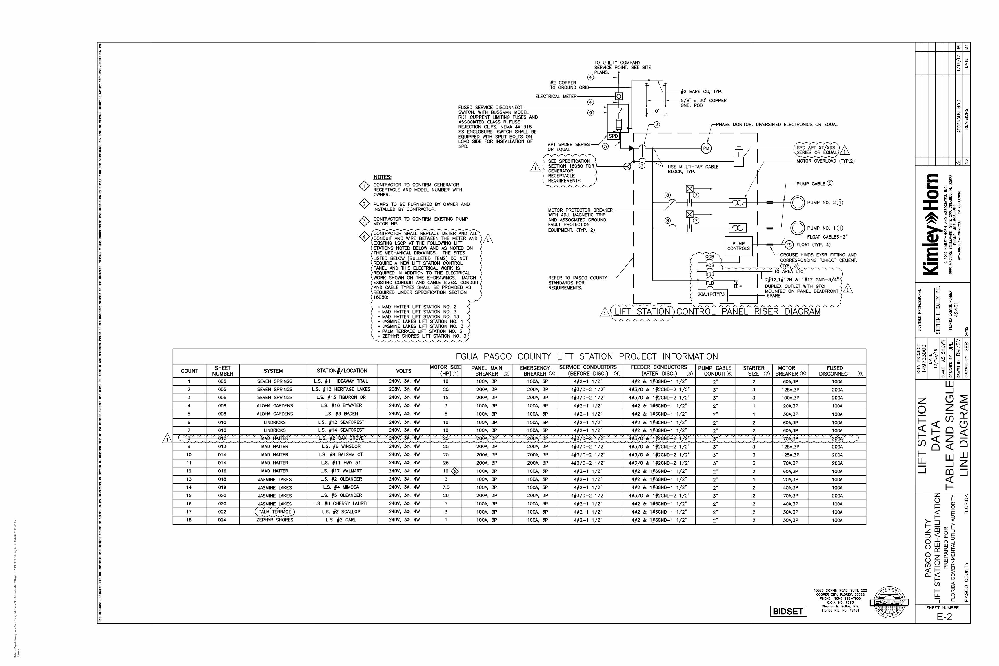
E-2
LIF
T S
TA
TIO
N
DA
TA
TA
BL
E A
ND
S
IN
GL
E
LIN
E D
IA
GR
AM
X:\A
ctive P
ro
jects\K
im
ley H
orn
\P
asco
C
ou
nty Lift Statio
ns\03._A
dd
en
du
m N
o. 1\D
wg
s\E-2-P
UM
P R
ISER
D
IA
.d
wg
, 24x36, 1/20/2017 11:15:21 A
M,
slo
go
fatu

E-3
ELE
CT
RIC
AL P
LA
N
VIE
W A
ND
E
LE
CT
RIC
AL
DE
TA
ILS
X:\A
ctive P
ro
jects\K
im
ley H
orn
\P
asco
C
ou
nty Lift Statio
ns\03._A
dd
en
du
m N
o. 1\D
wg
s\E-3-ELEC
TR
IC
AL P
LA
N V
IEW
.d
wg
, 24x36, 1/20/2017 11:14:59 A
M,
slo
go
fatu


