
FLEXIBLE LINERS& FLUE BOXESFor relining existing chimneys to take gas, oil and multi-fuelappliances including stoves & open fires.
n Single skin Wonderflex and Triplelockfor gas and oil (28 sec)
n Twin skin Tecnoflex (Turboflex Plus) foroil and multi-fuel
n Diameter range 80 - 400mm
DOC/CP3/40 Issue 5 Apr 2007

2
ApplicationFlexible flue and chimney liners designed for lining an existing flue or chimney.
Wonderflex and Triplelock are single wall stainless steel flexible flue liners designed for atmospheric gas and kerosene appliances where the flue gas temperature does not exceed 260°C. Diameter range Wonderflex 100 - 200mm,Triplelock 80 - 500mm.
Tecnoflex (Turboflex Plus) is a twin skin flexible chimney liner designed for gas, oil and multifuel, where the maximum flue gastemperature does not exceed 600°C. Diameter range 80 - 400mm.
Product Description
Single Wall Liners
n Made from corrosion-resistant 316L stainless steel.
n Leak resistant construction due to continuous weld(Wonderflex) or dovetail folded seam (Triplelock).
n Highest corrosion resistance.
n Deep corrugations for high crush resistance andbetter flexibility when installing.
n Strong seam construction resists the rigours ofpulling the liner into place during construction.
Twin Wall Liner
n Both inner and outer layers made from corrosion-resistant 316L stainless steel.904L stainless steel is also available as an option for the extreme conditionsfound with appliances like slumbering stoves.
n Corrugated outer skin for high crush resistance.
n Smooth inner skin resists corrosive attack due to easy drain down of condensate,less opportunity for soot collection and smooth surface for ease of sweeping.
n Inner skin remains overlapping to protect the joint from corrosion penetrationeven at minimum bending radius.
n Inner skin remains smooth and protective even after the rigours of installation.
overlap seam weld dovetail folded triplelock seam
Wonderflex Triplelock
Tecnoflex (Turboflex Plus)
direction offlue gas flow
ApprovalsWonderflex and Triplelock are both tested and Kitemarked to BS715:1993 in diameters l00, 125 and l50mm. Tecnoflex (Turboflex Plus),Wonderflex and Triplelock (Flexrite) are approved by HETAS and by CSTB (France) in diameters 125 to 200mm. All Rite-Ventflexible flue liners are manufactured under the stringent requirements of BS EN ISO 9001 - 2000 Quality management scheme.Tecnoflex (Turboflex Plus) is tested and approved by TÜV to EN 1856-1.

3
Flue Sizing
Wonderflex and Triplelock Tecnoflex (Turboflex Plus)
This information and sizes are provided as a nominal guide only. Flue sizing for appliances, particularly commercial/industrialapplications will vary depending on siting details and appliance manufacturer’s instructions and design criteria. These will overridethe sizing guide below and reference must be made to appliance manufacturer.
Flue Size Selection Guide Flue Size Selection Guide
Notes: 1 Subject to appliance manufacturer’s testing criteria.2 Subject to manufacturer’s input rating and chimney height.3 Subject to manufacturer’s output rating and chimney height.4 Min 300mm depending on opening, chimney size and height.S Smokeless fuel only.SC Smokeless fuel or coal.
Gas - Atmospheric BoilerInput up to 25kw •Input 25kw to 40kw •Input 40kw to 60kw •
Gas - Commercial/Industrial BoilersInput up to 50kw to 70kw •2
Gas Fires‘Radiant’ - BS7977-1 2002 •‘Inset’ - BS7977-1 2002 •1 •1‘Backboiler’ - BS7977-2 2003 •
Gas Water HeatersInput up to 25kw • •Input 25kw to 55kw •Input 55kw to 60kw •Input over 60kw •2
Gas Warm Air UnitsInput up to 18kw •Input 18kw to 35kw •Input 35kw to 60kw •Input over 60kw •2
Gas Stove/Cooker •2 •2 •2
Kerosene (28 sec Class C2) Heating BoilerOutput up to 25kw •Input 25kw to 45kw •Input 45kw to 70kw •
Kerosene Stove/Cooker •3 •3 •3
Kerosene Water HeaterInput up to 41kw •
Kerosene Visual EffectStoveOutput up to 17kw •3 •3
Gas Boiler - Forced DraughtInput up to 25kw •Input 25kw to 45kw •Input 45kw to 50kw •Input 50kw to 75kw •Input 75kw to 100kw •Input over 100kw • •2
Gas Fires‘Inset’ to BS7977-1 2002 •1‘Decorative’ to •BSEN 509:2000
Gas Oil (35 sec Class D) Heating BoilerOutput up to 25kw •Input 25kw to 45kw •Input 45kw to 70kw •Input 70kw to 100kw •Output over 100kw •3 •3 •3
Solid FuelHeating BoilerOutput up to 20kw •S •SC
Output 20kw to 30kw •S •SC •SC
Output 30kw to 60kw •SC •SC •SC
Open Fires (Standard opening)
500mm x 550mm
‘Avant Garde’ FeatureOpen Fires
Room Heaters
Wood burning Stoves/Cookers.Use only seasoned wood which has been stored 1/2 years in dry conditions.
Inglenook or nonstandard opening.The Cross sectional area of the chimney liner must be a minimum of 15% of the total cross sectional area of the fireplace opening.
80mm
180 to400mm
100mm
130mm
150mm
100mm
250 to400mm
130mm
150mm
180mm
200mm
230mm
Notes: 1 Subject to appliance manufacturer’s testing criteria.2 Subject to manufacturer’s input rating and chimney height.3 Subject to manufacturer’s output rating and chimney height.4 Min 300mm depending on opening, chimney size and height.S Smokeless fuel only.SC Smokeless fuel or coal.
200min•
180min•
230min•
•4
•S
•
4
System Design
Gas burningInput up to 45kw
Kerosene burningOutput up to 45kw
Gas/Oil burningOutput up to 45kw
Solid Fuel burningOutput up to 45kw
Appliance Chimneys builtbefore 1.2.1966
Chimneys builtafter 1.2.1966
BS Wonderflex or Triplelock can be used inunlined chimney
F.G.T. under 260˚BS715 Wonderflex orTriplelock can be used inunlined chimney &surrounding airspace insulated
Turboflex Plus can be usedin unlined chimney & surrounding airspace insulated
Turboflex Plus can be usedin unlined chimney &surrounding airspace insulated & ventilated
BS Wonderflex orTriplelock can be used in lined chimney
F.G.T. over 260˚BS715 Wonderflex or Triplelock can be used inlined chimney & surroundingairspace insulated
Turboflex Plus can be usedin lined chimney & surrounding airspace insulated
Turboflex Plus can be usedin lined chimney &surrounding airspace insulated & ventilated
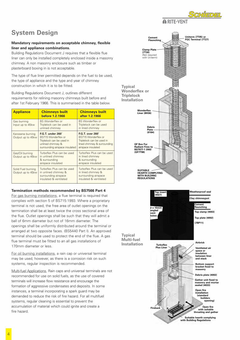
Termination methods recommended by BS7566 Part 4For gas burning installations, a flue terminal is required thatcomplies with section 5 of BS715:1993. Where a proprietaryterminal is not used, the free area of outlet openings on thetermination shall be at least twice the cross sectional area ofthe flue. Outlet openings shall be such that they will admit aball of 6mm diameter but not of 16mm diameter. Theopenings shall be uniformly distributed around the terminal orarranged at two opposite faces. (BS5440 Part I). An approvedterminal should be used to protect the end of the flue. A gasflue terminal must be fitted to an all gas installations of170mm diameter or less.
For oil burning installations, a rain cap or universal terminalmay be used, however, as there is a corrosion risk on suchsystems, regular inspection is recommended.
Multi-fuel Applications, Rain caps and universal terminals are notrecommended for use on solid fuels, as the use of coveredterminals will increase flow resistance and encourage theformation of aggressive condensates and deposits. In someinstances, a terminal incorporating a spark guard may bedemanded to reduce the risk of fire hazard. For all multifuelsystems, regular cleaning is essential to prevent theaccumulation of material which could ignite and create a fire hazard.
Mandatory requirements on acceptable chimney, flexibleliner and appliance combinations.Building Regulations Document J requires that a flexible flueliner can only be installed completely enclosed inside a masonrychimney. A non masonry enclosure such as timber orplasterboard boxing in is not acceptable.
The type of flue liner permitted depends on the fuel to be used,the type of appliance and the type and year of chimneyconstruction in which it is to be fitted.
Building Regulations Document J, outlines differentrequirements for relining masonry chimneys built before andafter 1st February 1966. This is summarised in the table below.
Uniterm (7T05) orFGC Terminal (7T27)
CementFlaunching
Clamp Plate(7T30)(Not requiredwith Uniterm)
DebrisPlate(0164)
GF Box ForRadiant Fires toBS7977-1 2002(GF7T98)
SUITABLE HEARTH COMPLYINGWITH BUILDINGREGULATIONS
Typical Multi-fuelInstallation
Typical Wonderflex orTriplelockInstallation
WonderflexLiner (8H36)
Top insert(4027)
Cementflaunching
Clay chimneypot
Weatherproof seal
2 x 15mmangledventtubes
Open fire with suitable
throating and gather
Suitable hearth complying with Building Regulations
Turboflex Plus Liner
Fireback
Open fireinstallation
(standard builders
opening)
Airbrick
Ventilated airspace or insulationbetween liner and stack
Bottom supportbracket fixed tomasonry
Gather unit fixed tomasonry and mortarsealed (4033)
Debris plate (4002)
(7BP11)
Top plate (4002)
Top clamp (4003)

5
Re-use of a previously capped or shortened chimney.The chimney can be reused providing the existing brickwork isinspected to ensure it is in good condition. The chimney can belined with the appropriate liner, ensuring that the liner is usedonly inside the stack. Connection to flue pipe - see Fig.1, or toBVent (gas), KVent (kerosene) or ICS (multifuel) system can bemade to the appliance/ termination, by using the appropriateconnector inside the chimney, and suitably sealed with firecement. The stack can be extended using ICS, BVent , KVent orICID depending on the application see Fig.2.
Re-use of a fitted flexible liner when changing the appliance.Provided the diameter and type of flex is suitable for the newappliance to be fitted and the installer has inspected the linerand is satisfied with its condition the liner can be reused.
However, as the lifespan of the previous appliance and liner maynot be known, it is strongly recommended the old flueliner isremoved, the chimney swept, then a suitable new liner installed.
Use of flue liner on condensing appliances.Wonderflex & Triplelock is not suitable for use on condensingappliances as the internal surface profile is convoluted and canhold aggressive residues caused by the flue gases which willattack and eventually corrode the stainless steel. Tecnoflex(Turboflex Plus) can be used on condensing appliances, whichhave pressure at the flue outlet of 100Pa maximum, andprovided the liner is insulated so condensation formation isminimised. It is also necessary to fit a tee and drain point atthe base of the vertical system, adequately supported, andconnected to a drainpipe to a suitable drain point.BVent
0°-90° Bend(1217)
BVent 275mm Wall Band(0123)
BVent 0°-90° Bend(1217)
BVent 450 Adj. Pipe (0208)
BVent 450 Pipe(1209)
BVent 900 Pipe (1202)
Ridge Terminal (0142)or CVTA (0128)
BVent Ridge TileAdaptor (0135)
Flex to BVentconnector (1278)
Clamp plate (7730)(not shown)
Typical Condensing Appliance Connection
135° TEEWITH TEE CAP(4001)
BOTTOMSUPPORTBRACKET(4009)
FLUEPIPE
APPLIANCE
DRAINPIPE(by others)
TOP PLATEUSED ASDEBRIS PLATE(4002)
TURBOFLEXPLUSADAPTOR(4015)
WonderflexLiner (8H36)
Fig. 1
Fig. 2
Clampplate(7T30)
BVent pipecontinuing totermination(1202)
INTERNAL STACKcapped off in roof space
Flex to BVentconnector (1278)
CementFlaunching
6
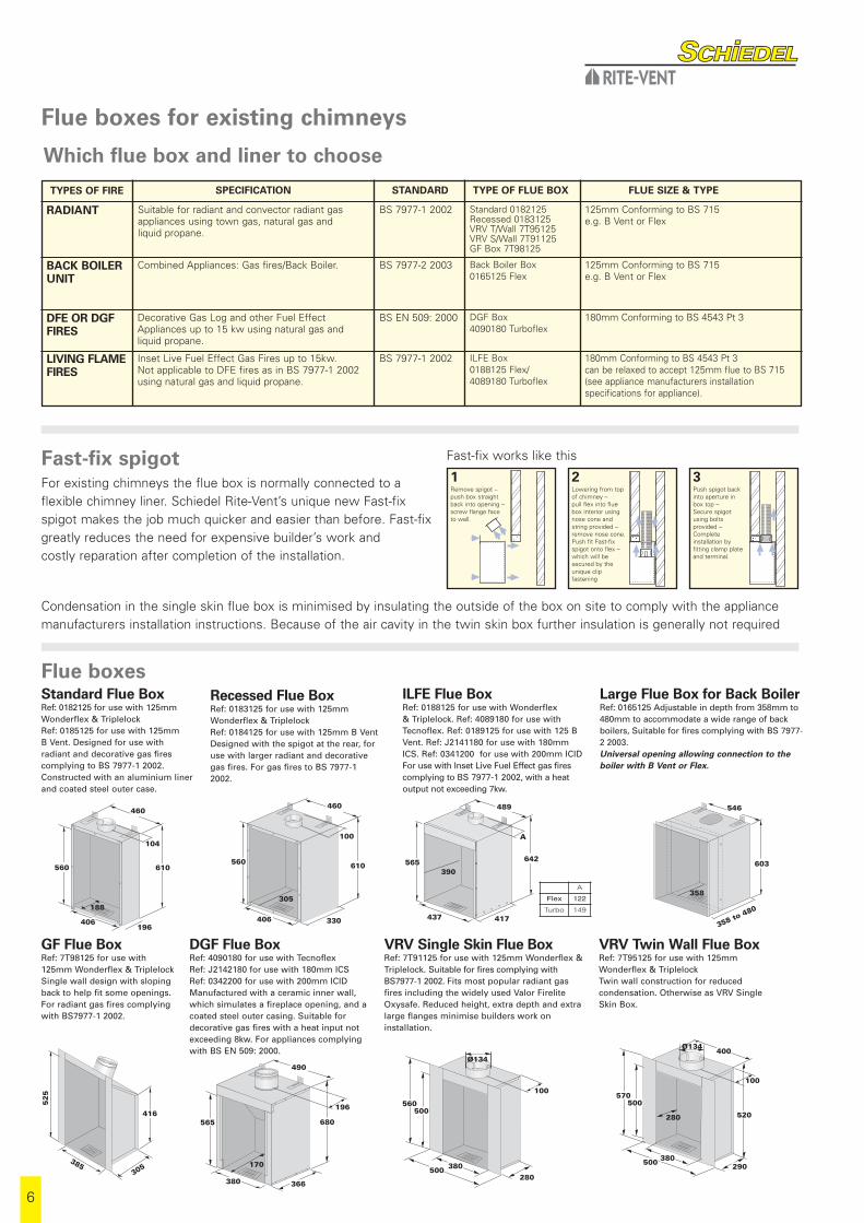
Fast-fix spigotFor existing chimneys the flue box is normally connected to aflexible chimney liner. Schiedel Rite-Vent’s unique new Fast-fixspigot makes the job much quicker and easier than before. Fast-fixgreatly reduces the need for expensive builder’s work and costly reparation after completion of the installation.
Flue boxes
460
610
104
196
560
406
188
Standard Flue BoxRef: 0182125 for use with 125mm Wonderflex & Triplelock Ref: 0185125 for use with 125mm B Vent. Designed for use withradiant and decorative gas firescomplying to BS 7977-1 2002.Constructed with an aluminium linerand coated steel outer case.
460
610
100
330
560
406
305
Recessed Flue BoxRef: 0183125 for use with 125mm Wonderflex & Triplelock Ref: 0184125 for use with 125mm B Vent Designed with the spigot at the rear, foruse with larger radiant and decorativegas fires. For gas fires to BS 7977-12002.
489
642
A
417
565
437
390
ILFE Flue BoxRef: 0188125 for use with Wonderflex & Triplelock. Ref: 4089180 for use withTecnoflex. Ref: 0189125 for use with 125 BVent. Ref: J2141180 for use with 180mmICS. Ref: 0341200 for use with 200mm ICIDFor use with Inset Live Fuel Effect gas firescomplying to BS 7977-1 2002, with a heatoutput not exceeding 7kw.
546
603
358 to 480
358
Large Flue Box for Back BoilerRef: 0165125 Adjustable in depth from 358mm to480mm to accommodate a wide range of backboilers, Suitable for fires complying with BS 7977-2 2003.Universal opening allowing connection to theboiler with B Vent or Flex.
GF Flue BoxRef: 7T98125 for use with 125mm Wonderflex & Triplelock Single wall design with slopingback to help fit some openings.For radiant gas fires complyingwith BS7977-1 2002.
DGF Flue BoxRef: 4090180 for use with Tecnoflex Ref: J2142180 for use with 180mm ICS Ref: 0342200 for use with 200mm ICIDManufactured with a ceramic inner wall,which simulates a fireplace opening, and acoated steel outer casing. Suitable fordecorative gas fires with a heat input notexceeding 8kw. For appliances complyingwith BS EN 509: 2000.
VRV Single Skin Flue BoxRef: 7T91125 for use with 125mm Wonderflex &Triplelock. Suitable for fires complying withBS7977-1 2002. Fits most popular radiant gasfires including the widely used Valor FireliteOxysafe. Reduced height, extra depth and extralarge flanges minimise builders work oninstallation.
VRV Twin Wall Flue BoxRef: 7T95125 for use with 125mmWonderflex & Triplelock Twin wall construction for reducedcondensation. Otherwise as VRV SingleSkin Box.
Which flue box and liner to choose
Remove spigot –push box straightback into opening –screw flange faceto wall.
Lowering from topof chimney –pull flex into fluebox interior usingnose cone andstring provided –remove nose cone.Push fit Fast-fixspigot onto flex –which will besecured by theunique clipfastening
Push spigot backinto aperture inbox top –Secure spigotusing boltsprovided –Completeinstallation byfitting clamp plateand terminal.
1 2 3
Condensation in the single skin flue box is minimised by insulating the outside of the box on site to comply with the appliancemanufacturers installation instructions. Because of the air cavity in the twin skin box further insulation is generally not required
Fast-fix works like this
560500
380500280
Ø134
100
52
5
305385
416
490
680
196
366
565
380
170
570500
280
380500 290
Ø134
100
400
520
A
Flex 122
Turbo 149
Flue boxes for existing chimneys
FLUE SIZE & TYPETYPE OF FLUE BOXSTANDARDSPECIFICATION
Suitable for radiant and convector radiant gasappliances using town gas, natural gas and liquid propane.
Combined Appliances: Gas fires/Back Boiler.
BS 7977-1 2002 Standard 0182125Recessed 0183125VRV T/Wall 7T95125VRV S/Wall 7T91125GF Box 7T98125
125mm Conforming to BS 715e.g. B Vent or Flex
BS 7977-2 2003 Back Boiler Box0165125 Flex
125mm Conforming to BS 715e.g. B Vent or Flex
Decorative Gas Log and other Fuel EffectAppliances up to 15 kw using natural gas andliquid propane.
BS EN 509: 2000 DGF Box4090180 Turboflex
180mm Conforming to BS 4543 Pt 3
Inset Live Fuel Effect Gas Fires up to 15kw. Not applicable to DFE fires as in BS 7977-1 2002using natural gas and liquid propane.
BS 7977-1 2002 ILFE Box0188125 Flex/4089180 Turboflex
180mm Conforming to BS 4543 Pt 3can be relaxed to accept 125mm flue to BS 715(see appliance manufacturers installationspecifications for appliance).
TYPES OF FIRE
RADIANT
BACK BOILERUNIT
DFE OR DGFFIRES
LIVING FLAMEFIRES

7
Wonderflex and Triplelock Accessories
Clamp and Plate
FGC Economy Terminal
Int Ø mm 100 125 150Part No. 7T26100 7T27125 7T28150
Int Ø mm 180 200 225 250 300 350 400Part No. 7T32180 7T33200 7T34225 7T47250 7T48300 7T49350 7T50400
Clamp Plate (2 piece)
Int Ø mm 100 125 150Part No. 7T29100 7T30125 7T31150
Int Ø mm 100 125 150
Debris Plate 0164
This item is used to seal the space between the linerand the chimney at the base of the stack.
Int Ø mm 125
Uniterm Type A 7T05125
This Uniterm assembly is designed to be installed to a potless chimney. (Typical 9”x 9”stack)
Tested and Certified to BS715: 1993
Int Ø mm 125
Uniterm Type B 7T04125
This Uniterm assembly is designed to be installed directly to the top of an existing round chimney pot.
Tested and Certified to BS715: 1993
Cast Aluminium Terminal
Int Ø mm 100 125Part No. 7T16100 7T15125
Int Ø mm 100 125 150 180 225 250 300 350 400
Universal Terminal 7T41
This item is manufactured in accordance with the requirements of BS5440.
Wonderflex and Triplelock Single Wall LinersAvailable in either drums or individual packs for the most common sizes.
Drums Drums available for diameters 80,100,125, 150, 180, 200, 225 and 250mm.
300, 350 and 400mm diameters are only available in 10m lengths.
Drum length 80 metres for 100mm and 125mm, reducing thereafter. See price list for full details.
Packs PACKS available for 100mm and 125mm diametersin the following lengths:
Length metres 6 7 8 9 10 11 12 13 14 15
Code 20 23 27 30 33 36 40 43 46 49
When ordering state: Product Code / Length Code / Diameter.
e.g. to order an 11m pack of Wonderflex 125mmdiameter complete with clamp plate and terminalthe code would be 9E36125.
9H9G9E
8H8G8E
Wonderflex
Cut length
Cut length & clamp plate only
Cut length, clamp plate & terminal
Triplelock
Cut length
Cut length & clamp plate only
Cut length, clamp plate & terminal
ProductCode

8
Tecnoflex (Turboflex Plus) Accessories
Int Ø mm 125 155 180 200 230 250 300 350 400
Adaptor 4015
Use in conjunction with Prima Plus 1mm Single Wall 90° and 135°tees to connect to Tecnoflex (Turboflex Plus).
Int Ø mm 125 155 180 200 230 250 300 350 400
Joiner 4007
Suitable for use in joining lengths of Tecnoflex (Turboflex Plus)only when exceeding maximum coil length.
Int Ø mm 125 155 180 200 230 250 300 350 400
Appliance Connector 4013
This item is used to connect from the appliance to Tecnoflex(Turboflex Plus).
Int Ø mm 125 155 180 200 230 250 300 350 400
Top Clamp 4003
This item is used in conjunction with the top plate to secure the linerat the top of the stack. Can also be used as an intermediate support.
Int Ø mm 125 155 180 200 230 250 300 350 400
Increaser Adaptor 4014
This item is used to increase from Prima Plus 1mm Single Wallto the next diameter of Tecnoflex (Turboflex Plus).
Int Ø mm 125 155 180 200 230 250 300 350 400
Top Plate 4002
This item is used in conjunction with the top clamp to support the liner atthe top of the stack. Can also be used as an intermediate support and to
be used as a debris plate above the appliance, gather unit or flue box.
Int Ø mm 125 155 180 200 230 250 300 350 400
90° Tee with Drain 4005
Int Ø mm 125 155 180 200 230 250 300 350 400
Universal Terminal 7T42
This item is manufactured in accordance with the requirementsof BS5440 and suitable for use on gas and oil applications only.Int Ø mm 125 155 180 200 230 250 300 350 400
135° Tee with Drain 4011
Int Ø mm 180 200
Gather Unit 4033
Int Ø mm 125 155 180 200 230 250 300 350 400
Bottom Support Bracket 4009
For use where a tee is fitted to the base of the stack. Can alsobe used as an intermediate support.
Int Ø mm 125 155 180 200 230 250 300 350 400
Top Insert 4027
Int Ø mm 125 155 180 200 230 250 300 350 400
Nose Cone 4004
For attaching to one end of Tecnoflex (Turboflex Plus) in order tofacilitate the installation of the liner into the chimney stack.
Tecnoflex (Turboflex Plus) Twin Wall Liners
Packs containing the cut length with clamp plate and nose cone are also available for 125, 150,180 & 200mm diameters. When ordering state Product Code followed by Diameter. eg. a 12m pack of 150mm Tecnoflex (Turboflex Plus) is TPF12150.
Tecnoflex (Turboflex Plus) is available for all diameters: 80, 100, 125, 155, 180, 200, 230, 250,300, 350 & 400mm as cut lengths. When ordering state Product Code followed by Diameter. eg. a 9m carton of 180mm Turboflex Plus is TPB09180.
TPBTPF
Tecnoflex (Turboflex Plus)
Cut length
Cut length, clamp plate & nose cone
ProductCode
230

9
InstallationMandatory Requirements
Connection to an appliance which is not connected to the fuelsupply, should be carried out by a competent person.However, connection to an appliance that is connected to thefuel supply must be carried out by a CORGI (gas), OFTEC (oil)or a HETAS registered installer.
Prior to installationIn all cases the chimney should be inspected for deteriorationand if necessary any remedial work required should be carriedout. The chimney should be swept, preferably by a member of NACS (National Association of Chimney Sweeps) or a suitablyqualified chimney sweep who would provide a certificate aftersweeping and checking, which should be retained for future reference.
It will be necessary to check that the flaunching at the top of the stack is not cracked, and if so replaced. The brickworkpointing and the flashings should be checked to ensure theyare in good order and corrected as necessary.
Installation of the linerThe flue liner should be pulled down the chimney using a nose cone and string/rope. All Wonderflex & Triplelock packsare supplied with a nose cone.
In the case of Tecnoflex (Turboflex Plus), a nose cone can bepurchased and connected to the end of the Tecnoflex(Turboflex Plus) by using self tapping screws.
lt is strongly recommended that a 1m test section, with nosecone attached, is pulled through the chimney prior toinstallation in order to ensure the chimney is suitably sized, andfree from obstructions. These can be purchased separatelyfrom your local distributor.
When securing the liner to the clamp plate or clamp band,ensure 75mm of liner is protruding to secure the terminal.
Liner OrientationIt is essential in the case of twin Wall Tecnoflex (TurboflexPlus) that the liner is installed the right way up. The arrow onthe outside of the liner indicates the direction of flue gas flowand must be pointing upwards towards termination. Gas flexcan be installed either way up.
Bending of the linerGreat care should be taken to avoid overbending or kinking theliner on installation. The minimum bending radii are shown inthe table below.
Insulation
If insulation is required, normally granules such as Vermiculite,should be poured in at this stage after fitting a suitable debrisplate at the bottom of the system. Alternatively a solid tube ofhigh quality insulation can be used.
Support of the liner.
Wonderflex & Triplelock is relatively light and can be supportedat the top of the chimney using a clamp plate fixed to the topof the masonry stack. Tecnoflex (Turboflex Plus) however, isheavier and must be supported using a separate plate andclamp securely fixed to the top of the stack. Where a tee isused at the base of the system to provide a drainpoint/cleaning access or connection to a flue pipe from theappliance, a bottom support bracket is required, fixed to the inside of the stack. In all cases, liner lengths exceeding 20 metres should beprovided with intermediate support, by using additional clampplates/support brackets.
Cutting the liner to the correct length for the chimney.After the length of flue liner has been connected to the appliance,allow at least 75mm of liner to protrude above the clamp plateand cut. For Wonderflex & Triplelock, an industrial knife can beused. For Tecnoflex (Turboflex Plus) use metal snips. The cut endsmust be secured using either electric tack welding or stainlesssteel rivets to avoid the liner risking unravelling. At all timesextreme care must be taken when cutting the liner and strongindustrial gloves plus long sleeved overalls should be worn as cutedges are very sharp. In addition, any tape secured to the ends ofthe liner, which is provided for safe handling prior to installation,must be removed before completion and commissioning of thefull system.
Sealing the flue liner to the chimney pot.The clamp plate or plate and clamp holding the liner to thechimney top should be fixed using screws and wall plugs. Toweather the top of the chimney stack and seal any gapsbetween the liner installation and the chimney pot appropriateacid resistant mortar should be used.
Connection of the Terminal to the flue liner.
For gas and oil systems, the terminal should be fitted over the protruding 75mm of liner and rivetted or secured using self tapping screws. On Turboflex Plus, where used on solidfuel appliances, a proprietary chimney pot must be fitted bybedding the pot on to the top plate.
Joining of flexible flue liner.
Flexible flue liners must be installed in continuous lengthswithout joiners. Schiedel Rite-Vent can supply all flue liners inspecific lengths on drums or in pack form upon request. OnTecnoflex (Turboflex Plus) installations, joiners are onlypermitted where the chimney liner length exceeds themaximum drum length available and details of the installationare agreed in advance, in writing, in compliance with product
Minimum Bending Radius (mm)
Product 80 100 125 155 180 200 230 250 300 350 400 450 500
WonderflexTriplelock 200 250 310 375 450 500 575 625 750 885 1000 1125 1250
Turboflex 240 300 375 465 540 600 690 750 900 1065 1200 - -
10
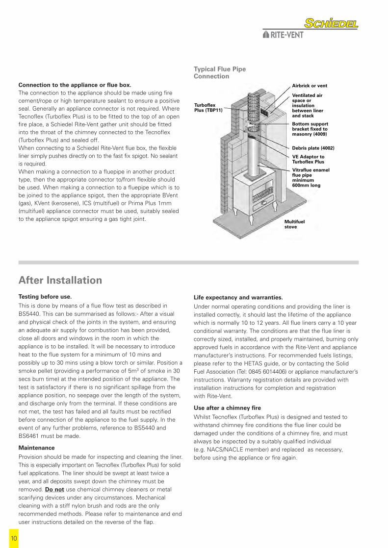
Connection to the appliance or flue box.The connection to the appliance should be made using firecement/rope or high temperature sealant to ensure a positiveseal. Generally an appliance connector is not required. WhereTecnoflex (Turboflex Plus) is to be fitted to the top of an openfire place, a Schiedel Rite-Vent gather unit should be fittedinto the throat of the chimney connected to the Tecnoflex(Turboflex Plus) and sealed off. When connecting to a Schiedel Rite-Vent flue box, the flexibleliner simply pushes directly on to the fast fix spigot. No sealant is required.When making a connection to a fluepipe in another producttype, then the appropriate connector to/from flexible shouldbe used. When making a connection to a fluepipe which is tobe joined to the appliance spigot, then the appropriate BVent(gas), KVent (kerosene), ICS (multifuel) or Prima Plus 1mm(multifuel) appliance connector must be used, suitably sealedto the appliance spigot ensuring a gas tight joint.
After InstallationTesting before use.
This is done by means of a flue flow test as described inBS5440. This can be summarised as follows:- After a visualand physical check of the joints in the system, and ensuringan adequate air supply for combustion has been provided,close all doors and windows in the room in which theappliance is to be installed. It will be necessary to introduceheat to the flue system for a minimum of 10 mins andpossibly up to 30 mins using a blow torch or similar. Position asmoke pellet (providing a performance of 5m3 of smoke in 30secs burn time) at the intended position of the appliance. Thetest is satisfactory if there is no significant spillage from theappliance position, no seepage over the length of the system,and discharge only from the terminal. If these conditions arenot met, the test has failed and all faults must be rectifiedbefore connection of the appliance to the fuel supply. In theevent of any further problems, reference to BS5440 andBS6461 must be made.
Maintenance
Provision should be made for inspecting and cleaning the liner.This is especially important on Tecnoflex (Turboflex Plus) for solidfuel applications. The liner should be swept at least twice ayear, and all deposits swept down the chimney must beremoved. Do not use chemical chimney cleaners or metalscarifying devices under any circumstances. Mechanicalcleaning with a stiff nylon brush and rods are the onlyrecommended methods. Please refer to maintenance and enduser instructions detailed on the reverse of the flap.
Life expectancy and warranties.
Under normal operating conditions and providing the liner isinstalled correctly, it should last the lifetime of the appliancewhich is normally 10 to 12 years. All flue liners carry a 10 yearconditional warranty. The conditions are that the flue liner iscorrectly sized, installed, and properly maintained, burning onlyapproved fuels in accordance with the Rite-Vent and appliancemanufacturer’s instructions. For recommended fuels listings,please refer to the HETAS guide, or by contacting the SolidFuel Association (Tel: 0845 6014406) or appliance manufacturer’sinstructions. Warranty registration details are provided withinstallation instructions for completion and registration with Rite-Vent.
Use after a chimney fire
Whilst Tecnoflex (Turboflex Plus) is designed and tested towithstand chimney fire conditions the flue liner could bedamaged under the conditions of a chimney fire, and mustalways be inspected by a suitably qualified individual (e.g. NACS/NACLE member) and replaced as necessary,before using the appliance or fire again.
Typical Flue Pipe Connection
Debris plate (4002)
TurboflexPlus (TBP11)
VE Adaptor toTurboflex Plus
Bottom supportbracket fixed tomasonry (4009)
Airbrick or vent
Ventilated airspace orinsulationbetween linerand stack
Vitraflue enamelflue pipe minimum600mm long
Multifuelstove

11
End User Maintenance1. Maintenance
CLEANING
It is recommended that chimneys serving solid fuel appliancebe swept as frequently as necessary but at least twice a year.Ideally this should take place in the middle of the heatingseason and at the end of the season. The chimney should beinspected at the start of the heating season for blockages,such as birds nests.
CLEANING METHODS
It is advised that only mechanical sweeping methods areused, chemical cleaners are not recommended. The services ofa professional chimney sweep should be employed.
2. Warning
Failure to maintain a clean chimney can result in the emissionof toxic gases into the dwelling or damage from potentialchimney fires. If a chimney fires does occur, professionaladvice should be sought regarding the condition of thechimney. The chimney should be inspected at least once ayear to see if the construction materials are in good condition.Particular attention should be paid to terminals, sectionsexternally exposed above the roof line and inspectionopenings. Should any component show any sign ofdeterioration, professional advice should be sought. It couldbe necessary to replace these components in order to ensurethat the chimney can operate correctly.
3. Fuels
It is advisable that only the fuel recommended by the appliancemanufacturer be used. Household refuse must not be burnt.Wood-burning produces considerable deposits of soot, tarrymatter and wood ash. The amount of these deposits can bereduced by burning well seasoned, air-dried (preferably 12-24months) wood, and by ensuring that an active bright fireis maintained.
4. Appliance Operation
If the appliance is slumbered overnight or for longer periodsthen it is advisable to run the appliance at controlled high firecondition for a period of at least 30 minutes. Prolongedslumbering of the appliance is a contributing factor to a linerfailure. It is important to maintain sufficiently high flue gastemperatures in order to avoid condensate and acid corrosion problems.
5. VentilationIt is very important that sufficient air for combustion andventilation is provided to the room containing the appliance to enable correct and efficient working of the appliance andchimney. Recommendations are given in the BuildingRegulations or CIBSE Guidance notes.
6. DowndraughtsThere are many possible causes of down-draught problemsincluding the height of the chimney. If these problems occur itis recommended that professional advice is sought. A rangeof anti-downdraught terminals are available.
More information on www.rite-vent.co.uk
INSTALLER HELPLINE
+44 (0) 191416 6666
Schiedel Rite-VentCrowther EstateWashingtonTyne & Wear NE38 OAQTel. +44 (0)191 416 1150Fax. +44 (0)191 415 [email protected]
Schiedel Chimney SystemsCarrickmacrossCo. MonaghanIrelandTel. +353 (0)42 966 1256Fax. +353 (0)42 966 2494 [email protected]
Every effort is made to ensure accuracy at time of going to press. However,as part of our policy of continual product development, we reserve the right toalter specifications without prior notice.
Other products in the Schiedel Rite-Vent range
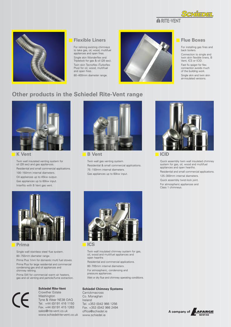
n Flexible LinersFor relining existing chimneysto take gas, oil, wood, multifuelappliances and open fires.
Single skin Wonderflex andTriplelock for gas & oil (28 sec).
Twin skin Tecnoflex (TurboflexPlus) for oil, wood, multifueland open fires.
80-400mm diameter range.
n Flue BoxesFor installing gas fires andback boilers.
Connection to single andtwin skin flexible liners, BVent, ICS or ICID.
Fast fix spigot for flexconnection avoids much of the building work.
Single skin and twin skinair-insulated versions.
n K VentTwin wall insulated venting system for oil (28 sec) and gas appliances.
Residential and small commercial applications.
100-150mm internal diameters.
Oil appliances up to 45kw output.
Gas appliances up to 60kw input.
Interfits with B Vent gas vent.
n B VentTwin wall gas venting system.
Residential & small commercial applications.
75 - 150mm internal diameters.
Gas appliances up to 60kw input.
n ICSTwin wall insulated chimney system for gas,oil, wood and multifuel appliances and open hearths
Residential and commercial applications.
80-705mm internal diameters.
For atmospheric, condensing andpressure appliances.
Wet or dry flue and chimney operating conditions.
n ICIDQuick assembly twin wall insulated chimneysystem for gas, oil, wood and multifuel appliances and open hearths.
Residential and small commercial applications.
125-300mm internal diameters.
Quick assembly twist-lock joint.
For atmospheric appliances and Class 1 chimneys.
n PrimaSingle wall stainless steel flue system.
80-755mm diameter range.
Prima Plus 1mm for domestic multi fuel stoves.
Prima Plus for large residential and commercialcondensing gas and oil appliances and chimney relining.
Prima SW for commercial warm air heaters, gas and oil venting and particle/fume extraction.
Schiedel Rite-VentCrowther EstateWashingtonTyne & Wear NE38 OAQTel. +44 (0)191 416 1150Fax. +44 (0)191 415 [email protected]
Schiedel Chimney SystemsCarrickmacrossCo. MonaghanIrelandTel. +353 (0)42 966 1256Fax. +353 (0)42 966 2494 [email protected]


