
Page 1Flare System - How to Simplify Three Projects' Execution
Flare System - How to Simplify Three Projects' ExecutionWhile Saving on Installation Cost and Improving Productivity
Marcio DonnangeloGlobal Business Development ManagerWireless Technologies
Page 2Flare System - How to Simplify Three Projects' Execution
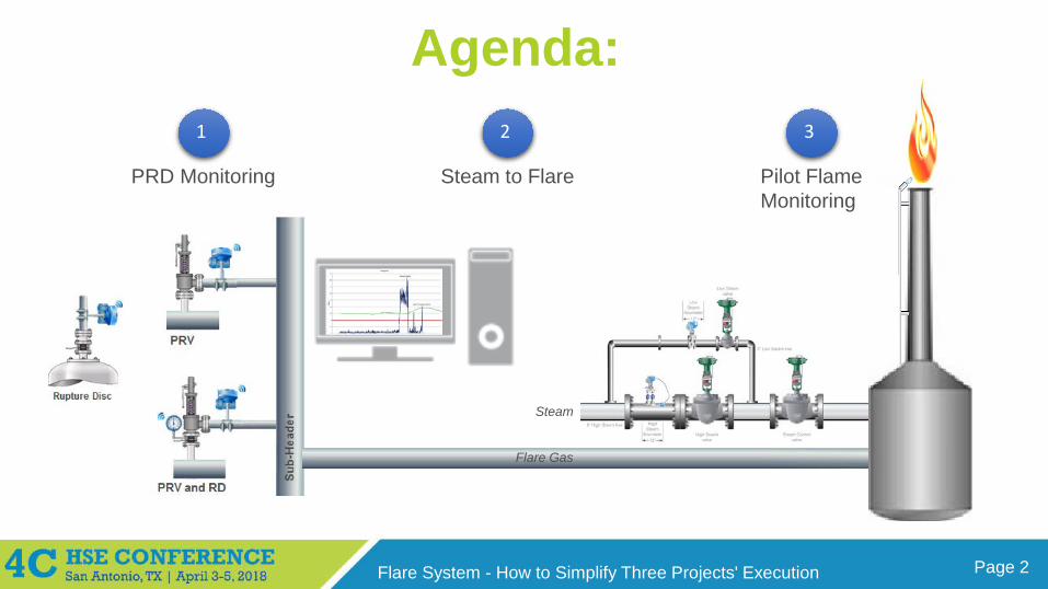
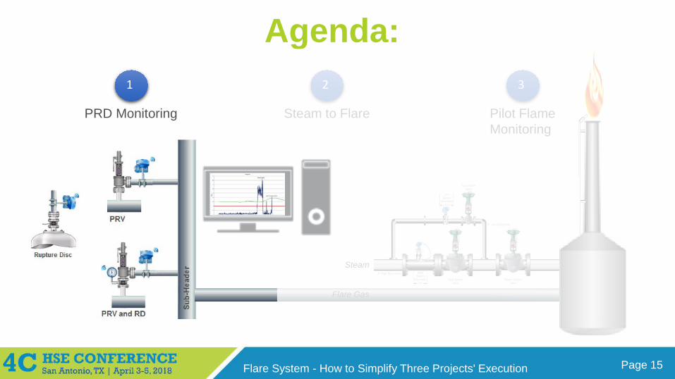
Agenda:1 2 3
Flare Gas
Steam
PRD Monitoring Steam to Flare Pilot FlameMonitoring

Page 3Flare System - How to Simplify Three Projects' Execution
Control Room,Security Room or
24/7 Location
Introduction toWirelessHART Industrial Network
Page 4Flare System - How to Simplify Three Projects' Execution
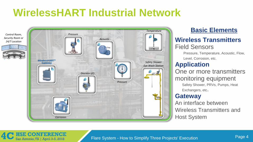
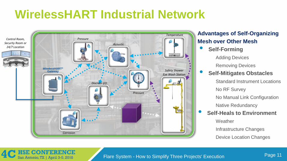
WirelessHART Industrial Network Basic Elements
Wireless Transmitters Field Sensors
Pressure, Temperature, Acoustic, Flow, Level, Corrosion, etc.
Application One or more transmitters monitoring equipment
Safety Shower, PRVs, Pumps, Heat Exchangers, etc.
GatewayAn interface between Wireless Transmitters and Host System
Pressure
Acoustic
Pressure
Corrosion
Temperature
WirelessHART®
Gateway
Discrete I/O
Control Room,Security Room or
24/7 Location
Safety Shower Eye Wash Station
Page 5Flare System - How to Simplify Three Projects' Execution
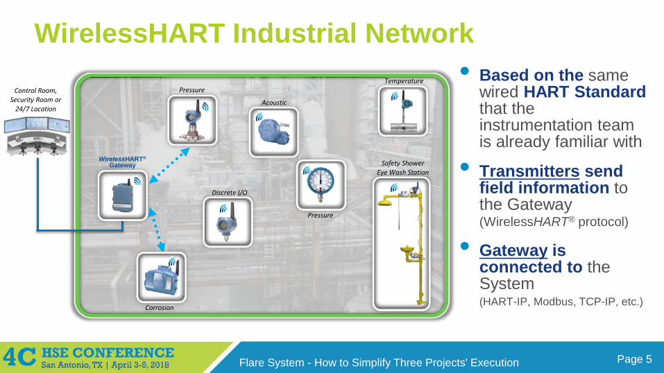
WirelessHART Industrial Network • Based on the same
wired HART Standard that the instrumentation team is already familiar with
• Transmitters send field information to the Gateway (WirelessHART® protocol)
• Gateway is connected to the System (HART-IP, Modbus, TCP-IP, etc.)
Pressure
Acoustic
Pressure
Corrosion
Temperature
WirelessHART®
Gateway
Discrete I/O
Control Room,Security Room or
24/7 Location
Safety Shower Eye Wash Station
Page 6Flare System - How to Simplify Three Projects' Execution
WirelessHART Industrial Network
Pressure
Acoustic
Pressure
Corrosion
Temperature
WirelessHART®
Gateway
Discrete I/O
Control Room,Security Room or
24/7 Location
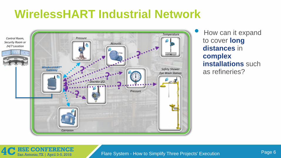
• How can it expand to cover long distances in complex installations such as refineries?Safety Shower
Eye Wash Station??
??
?
Page 7Flare System - How to Simplify Three Projects' Execution
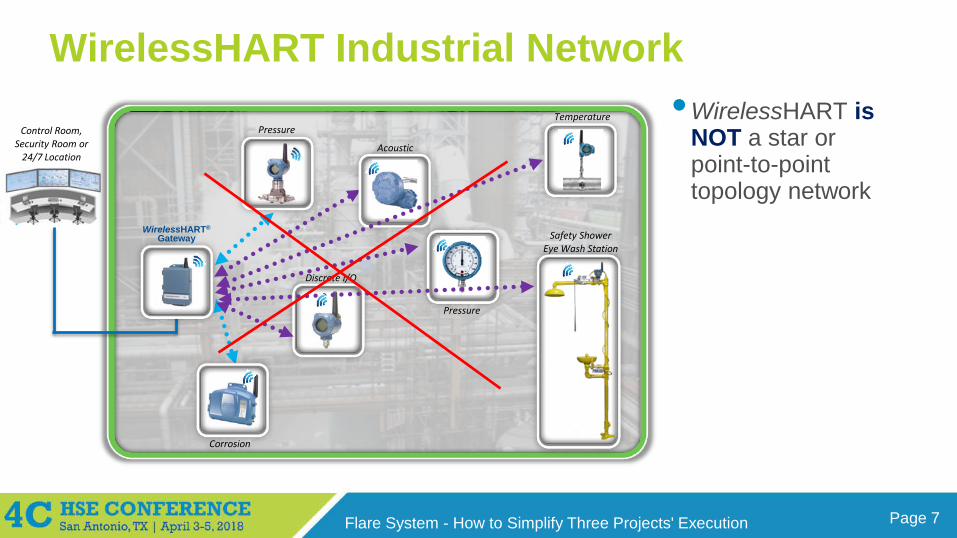
WirelessHART Industrial Network
Pressure
Acoustic
Pressure
Corrosion
Temperature
WirelessHART®
Gateway
Discrete I/O
Control Room,Security Room or
24/7 Location
•WirelessHART is NOT a star or point-to-point topology network
Safety Shower Eye Wash Station
Page 8Flare System - How to Simplify Three Projects' Execution
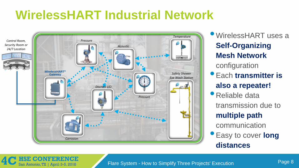
WirelessHART Industrial Network
Pressure
Acoustic
Pressure
Corrosion
Temperature
WirelessHART®
Gateway
Discrete I/O
Control Room,Security Room or
24/7 Location
•WirelessHART uses a Self-Organizing Mesh Network configuration
•Each transmitter is also a repeater!
•Reliable data transmission due to multiple path communication
•Easy to cover long distances
Safety Shower Eye Wash Station
Page 9Flare System - How to Simplify Three Projects' Execution
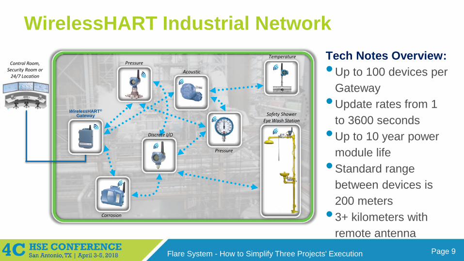
WirelessHART Industrial Network
Pressure
Acoustic
Pressure
Corrosion
Temperature
WirelessHART®
Gateway
Discrete I/O
Control Room,Security Room or
24/7 Location
Tech Notes Overview:•Up to 100 devices per
Gateway•Update rates from 1
to 3600 seconds•Up to 10 year power
module life•Standard range
between devices is 200 meters
• 3+ kilometers with remote antenna
Safety Shower Eye Wash Station
Page 10Flare System - How to Simplify Three Projects' Execution
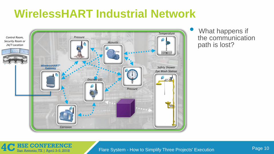
WirelessHART Industrial Network
Pressure
Acoustic
Pressure
Corrosion
Temperature
WirelessHART®
Gateway
Discrete I/O
Control Room,Security Room or
24/7 Location
Safety Shower Eye Wash Station
• What happens if the communication path is lost?
Page 11Flare System - How to Simplify Three Projects' Execution
WirelessHART Industrial Network
Pressure
Acoustic
Pressure
Corrosion
Temperature
WirelessHART®
Gateway
Discrete I/O
Control Room,Security Room or
24/7 Location
Safety Shower Eye Wash Station
Advantages of Self-Organizing Mesh over Other Mesh• Self-Forming
Adding Devices
Removing Devices• Self-Mitigates Obstacles
Standard Instrument Locations
No RF SurveyNo Manual Link Configuration
Native Redundancy
• Self-Heals to EnvironmentWeather
Infrastructure Changes
Device Location Changes

Page 12Flare System - How to Simplify Three Projects' Execution
Wireless Technology is the Lower Total Cost Solution for Missing Measurements

Page 13Flare System - How to Simplify Three Projects' Execution
Flare System - How to Simplify Three Projects' ExecutionWhile Saving on Installation Cost and Improving Productivity
Marcio DonnangeloGlobal Business Development ManagerWireless Technologies
Page 14Flare System - How to Simplify Three Projects' Execution
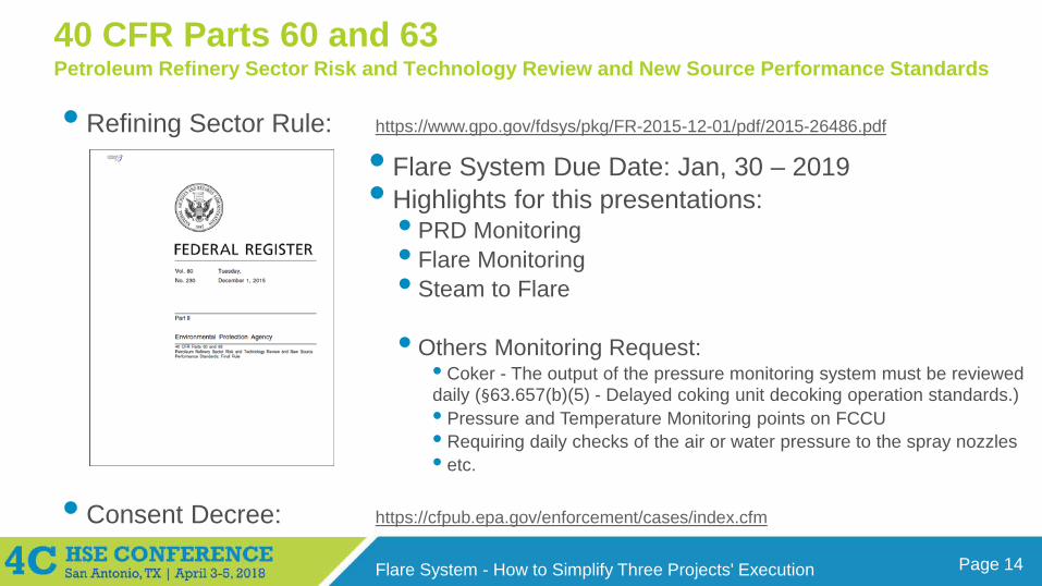
40 CFR Parts 60 and 63Petroleum Refinery Sector Risk and Technology Review and New Source Performance Standards
• Refining Sector Rule: https://www.gpo.gov/fdsys/pkg/FR-2015-12-01/pdf/2015-26486.pdf
• Flare System Due Date: Jan, 30 – 2019• Highlights for this presentations:
• PRD Monitoring• Flare Monitoring• Steam to Flare
• Others Monitoring Request:• Coker - The output of the pressure monitoring system must be reviewed daily (§63.657(b)(5) - Delayed coking unit decoking operation standards.)• Pressure and Temperature Monitoring points on FCCU• Requiring daily checks of the air or water pressure to the spray nozzles• etc.
• Consent Decree: https://cfpub.epa.gov/enforcement/cases/index.cfm
Page 15Flare System - How to Simplify Three Projects' Execution
Agenda:1 2 3
Flare Gas
Steam
PRD Monitoring Steam to Flare Pilot FlameMonitoring
Page 16Flare System - How to Simplify Three Projects' Execution
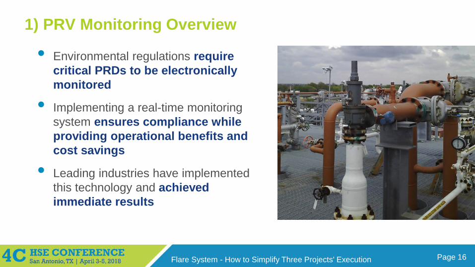
1) PRV Monitoring Overview
• Environmental regulations require critical PRDs to be electronically monitored
• Implementing a real-time monitoring system ensures compliance while providing operational benefits and cost savings
• Leading industries have implemented this technology and achieved immediate results
Page 17Flare System - How to Simplify Three Projects' Execution
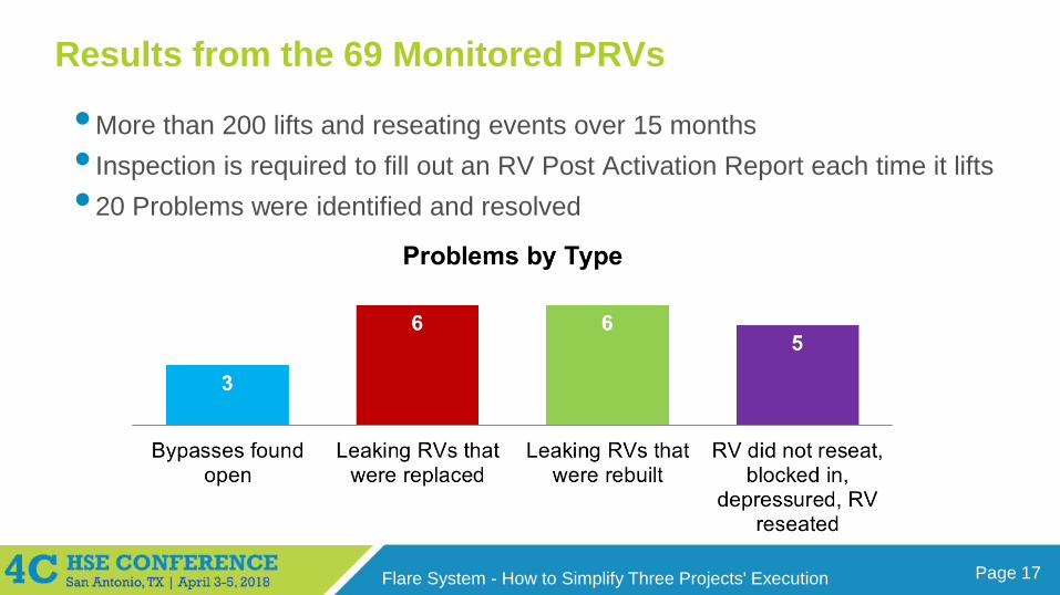
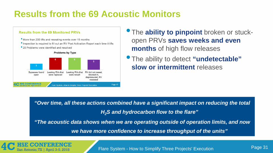
Results from the 69 Monitored PRVs
•More than 200 lifts and reseating events over 15 months• Inspection is required to fill out an RV Post Activation Report each time it lifts • 20 Problems were identified and resolved
Page 18Flare System - How to Simplify Three Projects' Execution
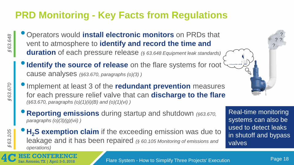
PRD Monitoring - Key Facts from Regulations
•Operators would install electronic monitors on PRDs that vent to atmosphere to identify and record the time and duration of each pressure release (§ 63.648 Equipment leak standards)
• Identify the source of release on the flare systems for root cause analyses (§63.670, paragraphs (o)(3) )
• Implement at least 3 of the redundant prevention measures for each pressure relief valve that can discharge to the flare(§63.670, paragraphs (o)(1)(ii)(B) and (o)(1)(vi) )
•Reporting emissions during startup and shutdown (§63.670, paragraphs (o)(3)(g)(vii) )
•H2S exemption claim if the exceeding emission was due to leakage and it has been repaired (§ 60.105 Monitoring of emissions and operations)
?? ?
?
Real-time monitoring systems can also be used to detect leaks in shutoff and bypass valves
§63
.670
§63
.648
§63
.105
Page 19Flare System - How to Simplify Three Projects' Execution
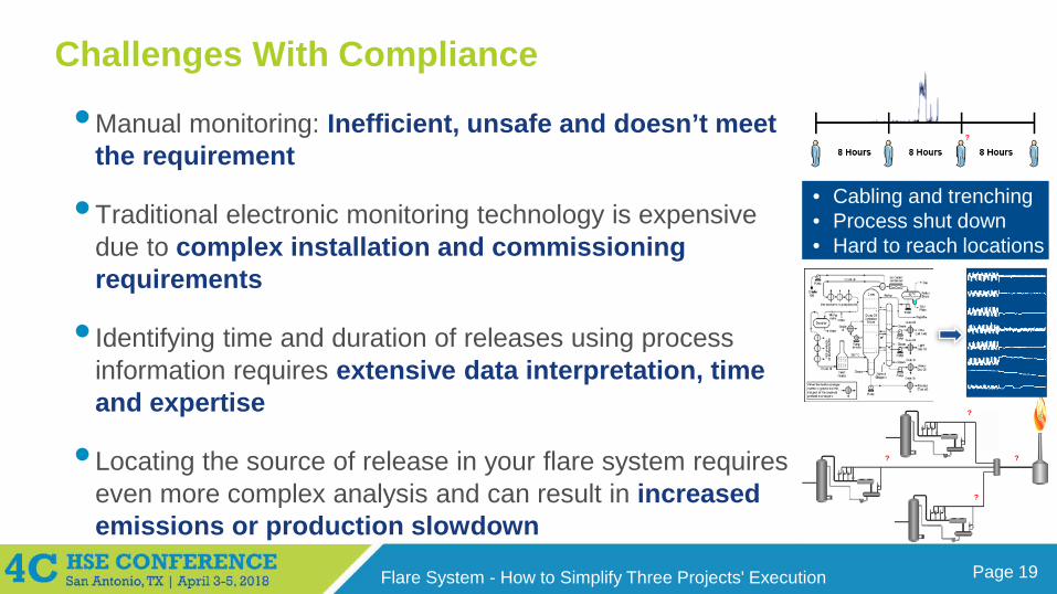
Challenges With Compliance
•Manual monitoring: Inefficient, unsafe and doesn’t meet the requirement
•Traditional electronic monitoring technology is expensive due to complex installation and commissioning requirements
• Identifying time and duration of releases using process information requires extensive data interpretation, time and expertise
•Locating the source of release in your flare system requires even more complex analysis and can result in increased emissions or production slowdown
• Cabling and trenching• Process shut down• Hard to reach locations
?
?
?
?
$
?
Page 20Flare System - How to Simplify Three Projects' Execution
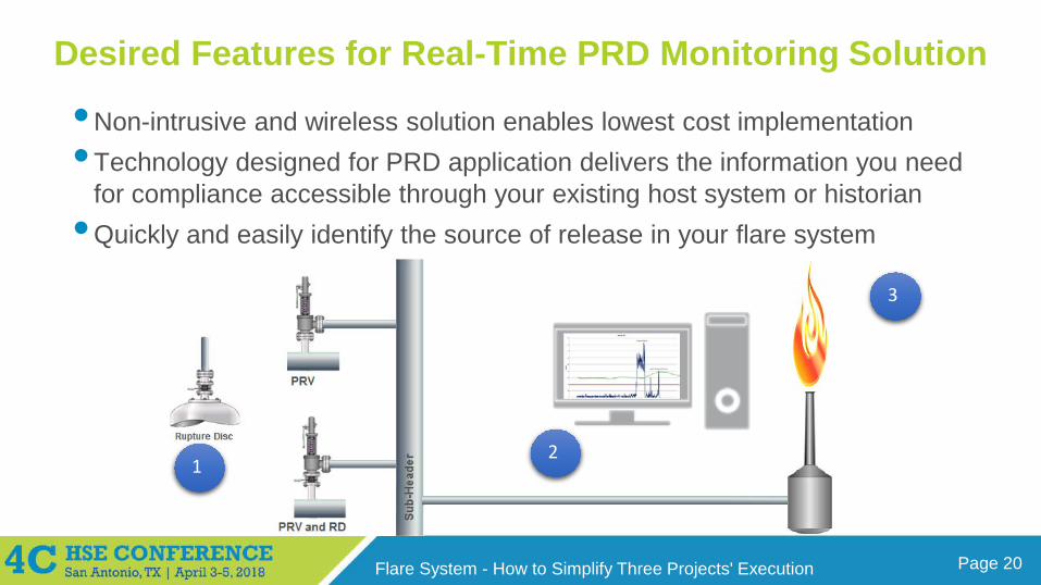
Desired Features for Real-Time PRD Monitoring Solution
•Non-intrusive and wireless solution enables lowest cost implementation • Technology designed for PRD application delivers the information you need
for compliance accessible through your existing host system or historian•Quickly and easily identify the source of release in your flare system
12
3
Page 21Flare System - How to Simplify Three Projects' Execution
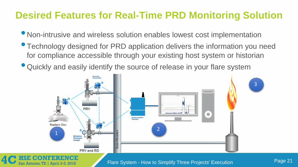
Desired Features for Real-Time PRD Monitoring Solution
•Non-intrusive and wireless solution enables lowest cost implementation • Technology designed for PRD application delivers the information you need
for compliance accessible through your existing host system or historian•Quickly and easily identify the source of release in your flare system
WirelessHART®
Gateway
Acoustic Transmitter
Wireless Pressure Gauge
12
3
Page 22Flare System - How to Simplify Three Projects' Execution
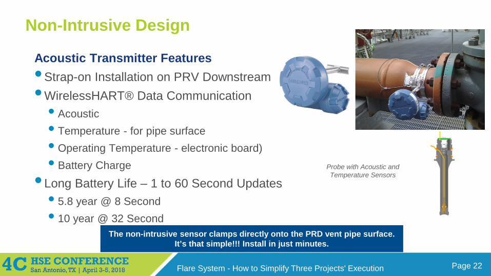
Non-Intrusive Design
Acoustic Transmitter Features•Strap-on Installation on PRV Downstream•WirelessHART® Data Communication
• Acoustic • Temperature - for pipe surface• Operating Temperature - electronic board)• Battery Charge
• Long Battery Life – 1 to 60 Second Updates• 5.8 year @ 8 Second• 10 year @ 32 Second
The non-intrusive sensor clamps directly onto the PRD vent pipe surface.It’s that simple!!! Install in just minutes.
Probe with Acoustic and Temperature Sensors
Page 23Flare System - How to Simplify Three Projects' Execution
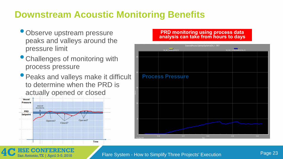
Downstream Acoustic Monitoring Benefits
•Observe upstream pressure peaks and valleys around the pressure limit
•Challenges of monitoring with process pressure
•Peaks and valleys make it difficult to determine when the PRD is actually opened or closed
AcousticProcess PressureProcess Pressure
Page 24Flare System - How to Simplify Three Projects' Execution
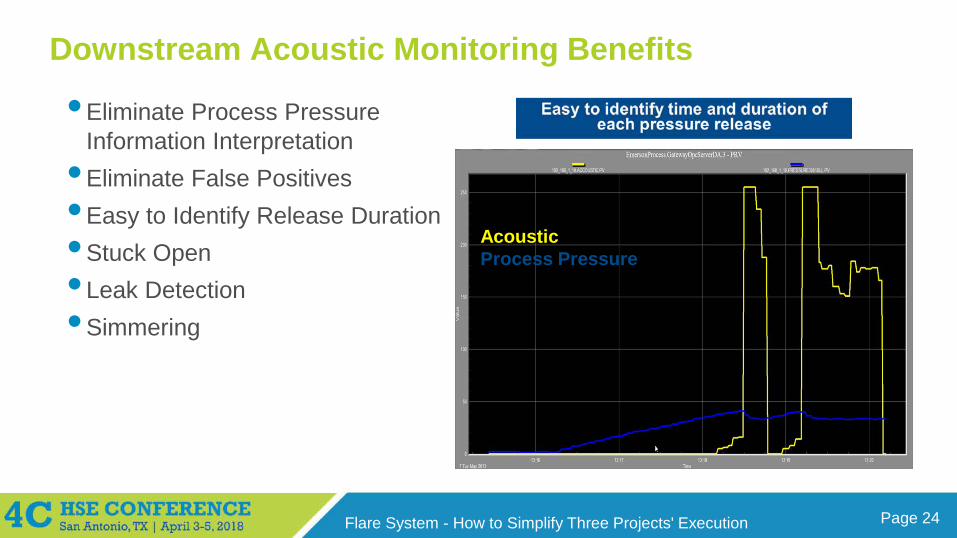
Downstream Acoustic Monitoring Benefits
•Eliminate Process Pressure Information Interpretation
•Eliminate False Positives •Easy to Identify Release Duration•Stuck Open•Leak Detection•Simmering
AcousticProcess Pressure
Page 25Flare System - How to Simplify Three Projects' Execution
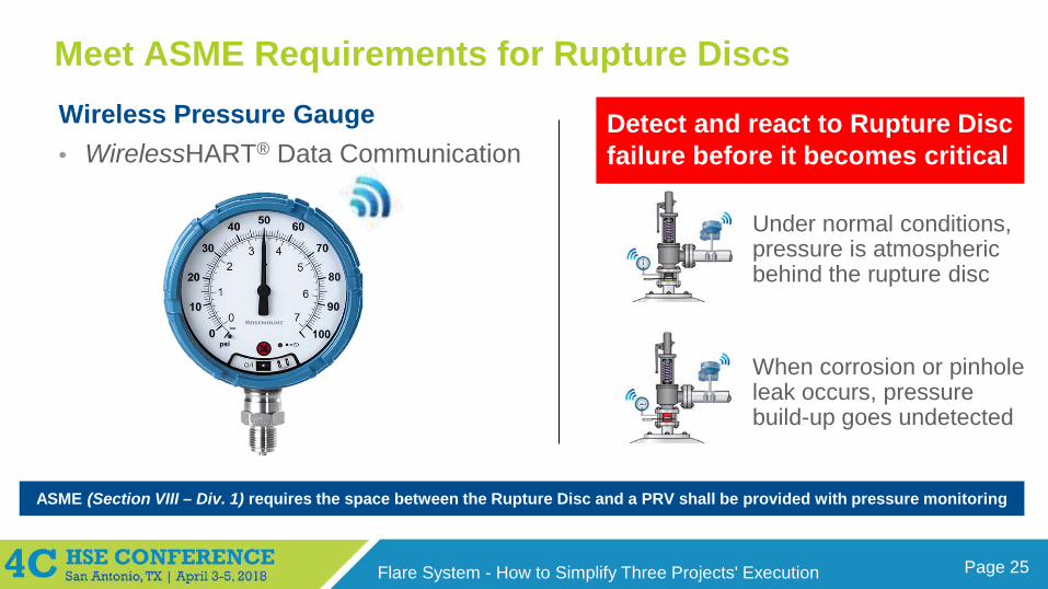
Meet ASME Requirements for Rupture DiscsWireless Pressure Gauge• WirelessHART® Data Communication
ASME (Section VIII – Div. 1) requires the space between the Rupture Disc and a PRV shall be provided with pressure monitoring
Detect and react to Rupture Disc failure before it becomes critical
Under normal conditions, pressure is atmospheric behind the rupture disc
When corrosion or pinhole leak occurs, pressure build-up goes undetected
Page 26Flare System - How to Simplify Three Projects' Execution
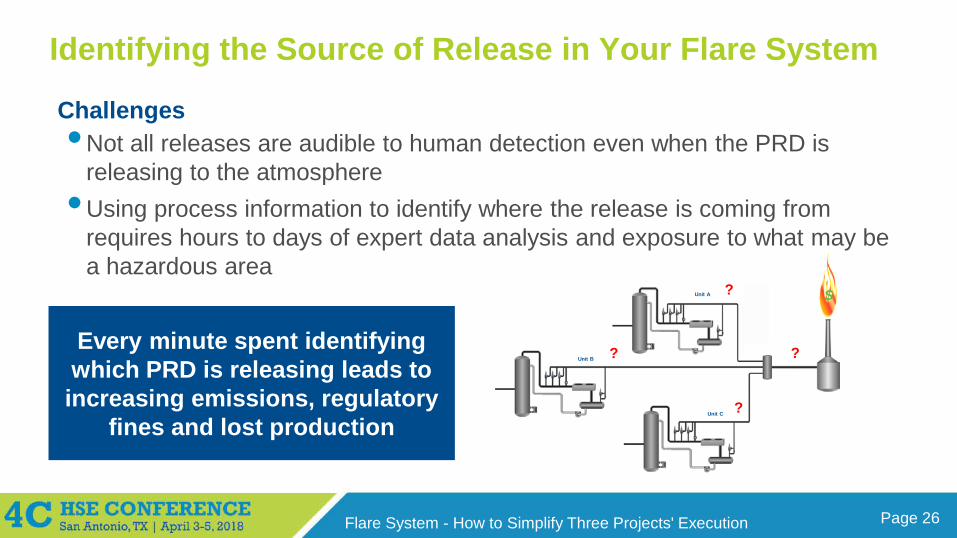
Identifying the Source of Release in Your Flare System
Challenges•Not all releases are audible to human detection even when the PRD is
releasing to the atmosphere•Using process information to identify where the release is coming from
requires hours to days of expert data analysis and exposure to what may be a hazardous area
Unit A
Unit B
Unit C
?
?
?
?
$
Every minute spent identifying which PRD is releasing leads to increasing emissions, regulatory
fines and lost production
Page 27Flare System - How to Simplify Three Projects' Execution
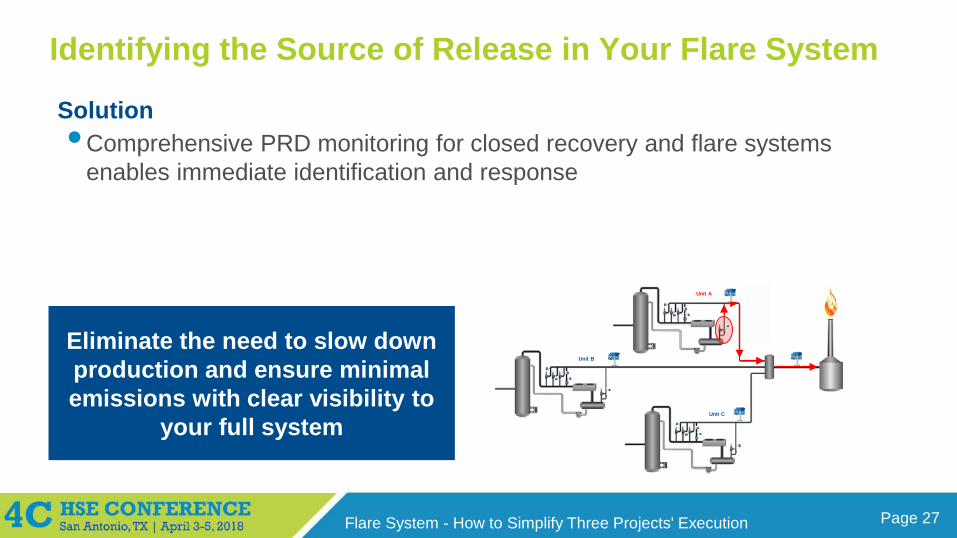
Identifying the Source of Release in Your Flare System
Solution•Comprehensive PRD monitoring for closed recovery and flare systems
enables immediate identification and response
Unit A
Unit B
Unit C
?
?
?
?
$
Eliminate the need to slow down production and ensure minimal emissions with clear visibility to
your full system
Unit A
Unit B
Unit C
Page 28Flare System - How to Simplify Three Projects' Execution
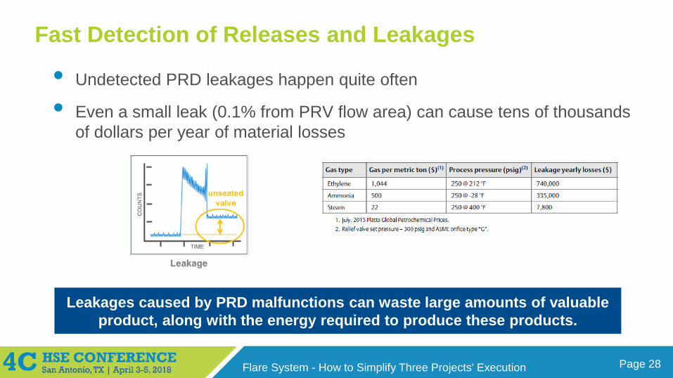
Fast Detection of Releases and Leakages
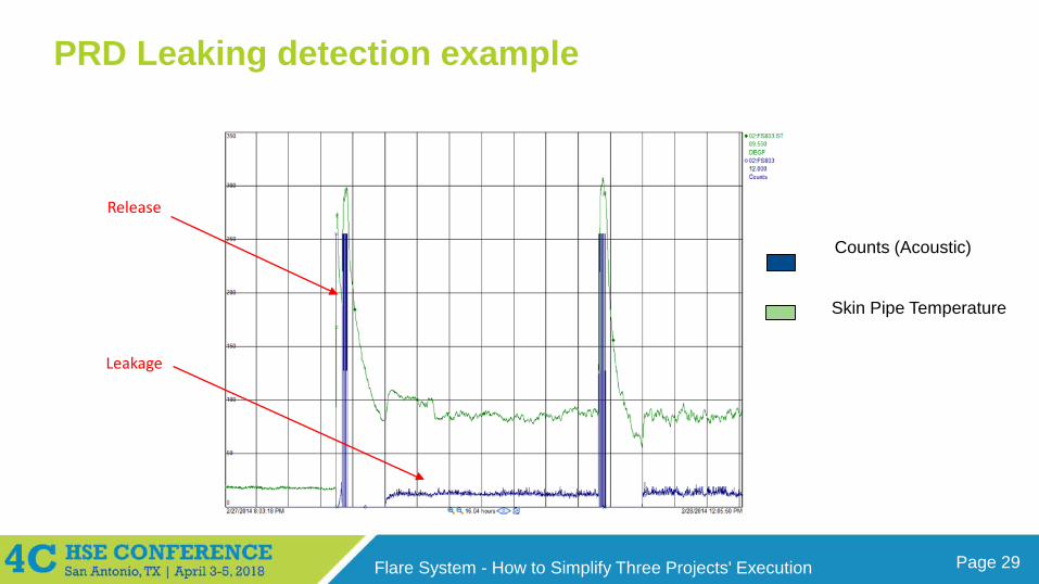
• Undetected PRD leakages happen quite often
• Even a small leak (0.1% from PRV flow area) can cause tens of thousands of dollars per year of material losses
Leakages caused by PRD malfunctions can waste large amounts of valuable product, along with the energy required to produce these products.
Page 29Flare System - How to Simplify Three Projects' Execution
PRD Leaking detection example
Counts (Acoustic)
Skin Pipe Temperature
Release
Leakage
Page 30Flare System - How to Simplify Three Projects' Execution
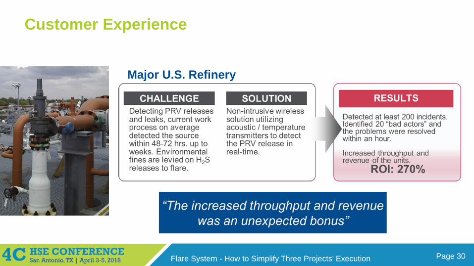
Customer Experience
Major U.S. Refinery
Page 31Flare System - How to Simplify Three Projects' Execution
Results from the 69 Acoustic Monitors
•The ability to pinpoint broken or stuck-open PRVs saves weeks and even months of high flow releases
•The ability to detect “undetectable” slow or intermittent releases
“Over time, all these actions combined have a significant impact on reducing the total H2S and hydrocarbon flow to the flare”
“The acoustic data shows when we are operating outside of operation limits, and now we have more confidence to increase throughput of the units”
Page 32Flare System - How to Simplify Three Projects' Execution
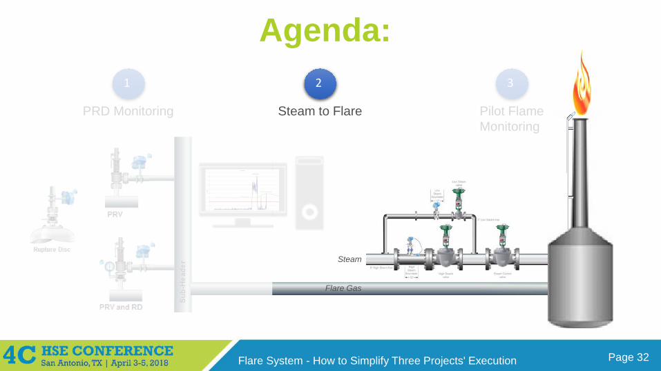
Agenda:1 2 3
Flare Gas
Steam
PRD Monitoring Steam to Flare Pilot FlameMonitoring
Page 33Flare System - How to Simplify Three Projects' Execution
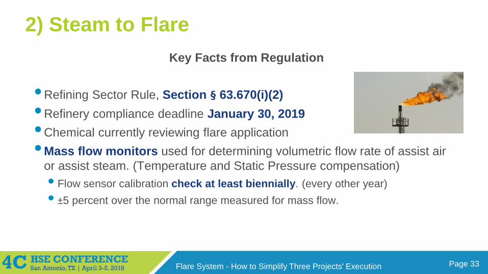
2) Steam to FlareKey Facts from Regulation
•Refining Sector Rule, Section § 63.670(i)(2)•Refinery compliance deadline January 30, 2019•Chemical currently reviewing flare application•Mass flow monitors used for determining volumetric flow rate of assist air
or assist steam. (Temperature and Static Pressure compensation)• Flow sensor calibration check at least biennially. (every other year)• ±5 percent over the normal range measured for mass flow.
Page 34Flare System - How to Simplify Three Projects' Execution
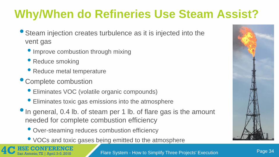
Why/When do Refineries Use Steam Assist?•Steam injection creates turbulence as it is injected into the
vent gas • Improve combustion through mixing• Reduce smoking• Reduce metal temperature
•Complete combustion • Eliminates VOC (volatile organic compounds) • Eliminates toxic gas emissions into the atmosphere
• In general, 0.4 lb. of steam per 1 lb. of flare gas is the amount needed for complete combustion efficiency• Over-steaming reduces combustion efficiency• VOCs and toxic gases being emitted to the atmosphere
Page 35Flare System - How to Simplify Three Projects' Execution
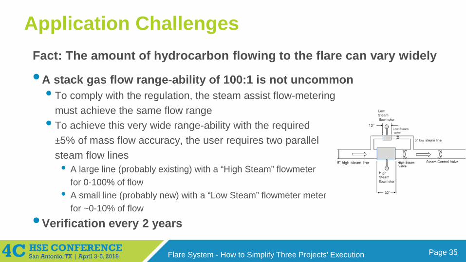
Application Challenges
•A stack gas flow range-ability of 100:1 is not uncommon• To comply with the regulation, the steam assist flow-metering
must achieve the same flow range• To achieve this very wide range-ability with the required
±5% of mass flow accuracy, the user requires two parallel steam flow lines • A large line (probably existing) with a “High Steam” flowmeter
for 0-100% of flow• A small line (probably new) with a “Low Steam” flowmeter meter
for ~0-10% of flow
•Verification every 2 years
Fact: The amount of hydrocarbon flowing to the flare can vary widely
Page 36Flare System - How to Simplify Three Projects' Execution
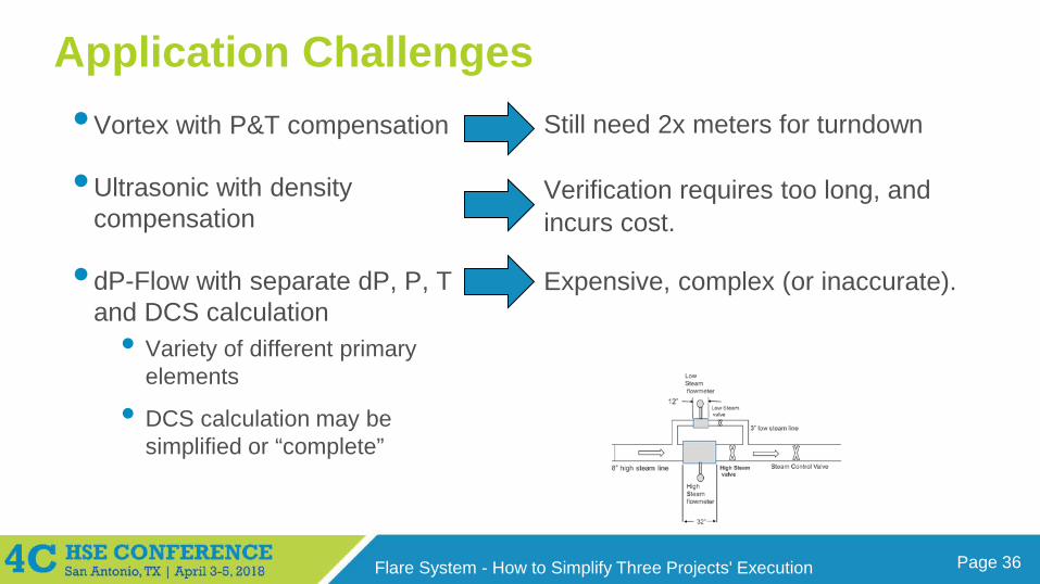
Application Challenges •Vortex with P&T compensation
•Ultrasonic with density compensation
• dP-Flow with separate dP, P, T and DCS calculation
• Variety of different primary elements
• DCS calculation may be simplified or “complete”
Still need 2x meters for turndown
Verification requires too long, and incurs cost.
Expensive, complex (or inaccurate).
Page 37Flare System - How to Simplify Three Projects' Execution
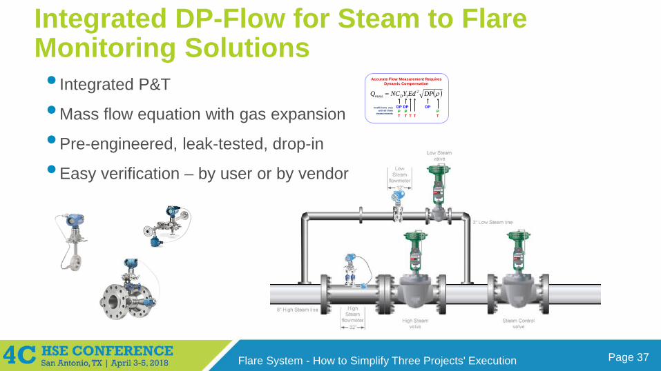
Integrated DP-Flow for Steam to Flare Monitoring Solutions• Integrated P&T
•Mass flow equation with gas expansion
•Pre-engineered, leak-tested, drop-in
•Easy verification – by user or by vendor
( )ρDPEdYNCQ Dmass2
1=
DP
TP
DPP PT TT T
Coefficients vary with all three
measurements
Accurate Flow Measurement Requires Dynamic Compensation
DP
Page 38Flare System - How to Simplify Three Projects' Execution
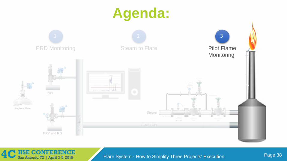
Agenda:1 2 3
Flare Gas
Steam
PRD Monitoring Steam to Flare Pilot FlameMonitoring
Page 39Flare System - How to Simplify Three Projects' Execution
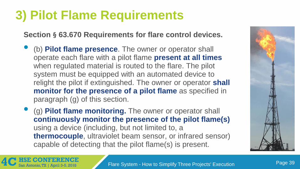
3) Pilot Flame RequirementsSection § 63.670 Requirements for flare control devices.
• (b) Pilot flame presence. The owner or operator shall operate each flare with a pilot flame present at all times when regulated material is routed to the flare. The pilot system must be equipped with an automated device to relight the pilot if extinguished. The owner or operator shall monitor for the presence of a pilot flame as specified in paragraph (g) of this section.
• (g) Pilot flame monitoring. The owner or operator shall continuously monitor the presence of the pilot flame(s)using a device (including, but not limited to, a thermocouple, ultraviolet beam sensor, or infrared sensor) capable of detecting that the pilot flame(s) is present.
Page 40Flare System - How to Simplify Three Projects' Execution
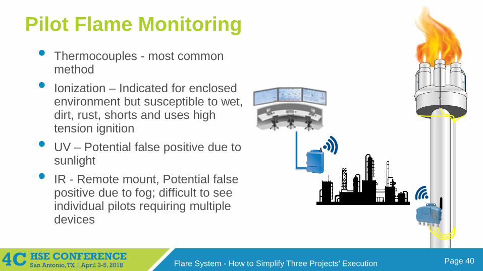
Pilot Flame Monitoring• Thermocouples - most common
method• Ionization – Indicated for enclosed
environment but susceptible to wet, dirt, rust, shorts and uses high tension ignition
• UV – Potential false positive due to sunlight
• IR - Remote mount, Potential false positive due to fog; difficult to see individual pilots requiring multiple devices
Page 41Flare System - How to Simplify Three Projects' Execution
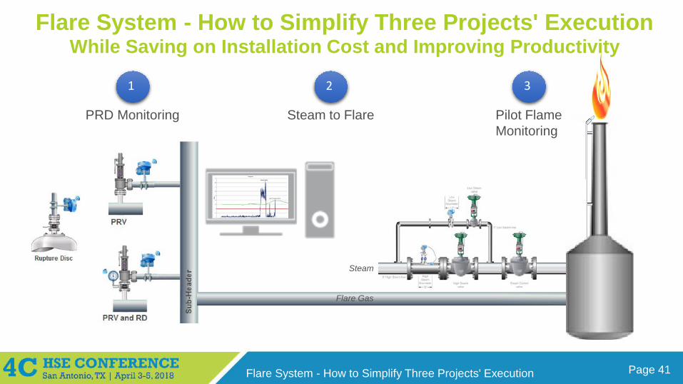
1 2 3
Flare Gas
Steam
PRD Monitoring Steam to Flare Pilot FlameMonitoring
Flare System - How to Simplify Three Projects' ExecutionWhile Saving on Installation Cost and Improving Productivity
Page 42Flare System - How to Simplify Three Projects' Execution
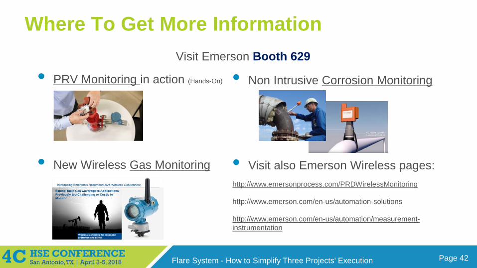
Where To Get More InformationVisit Emerson Booth 629
• PRV Monitoring in action (Hands-On)
• New Wireless Gas Monitoring
• Non Intrusive Corrosion Monitoring
• Visit also Emerson Wireless pages:http://www.emersonprocess.com/PRDWirelessMonitoring
http://www.emerson.com/en-us/automation-solutions
http://www.emerson.com/en-us/automation/measurement-instrumentation
Page 43Flare System - How to Simplify Three Projects' Execution
Thank You for Attending! Enjoy the rest of the conference
Marcio DonnangeloGlobal Business Development ManagerWireless Technologies


