
www.Fisher.com
Fisherr EHAD, EHAS, and EHAT ValvesContentsIntroduction 1. . . . . . . . . . . . . . . . . . . . . . . . . . . . . . . . .Scope of Manual 1. . . . . . . . . . . . . . . . . . . . . . . . . . . . .Description 2. . . . . . . . . . . . . . . . . . . . . . . . . . . . . . . . .Specifications 2. . . . . . . . . . . . . . . . . . . . . . . . . . . . . . .Installation 2. . . . . . . . . . . . . . . . . . . . . . . . . . . . . . . . . .Maintenance 4. . . . . . . . . . . . . . . . . . . . . . . . . . . . . . . . .Packing Lubrication 6. . . . . . . . . . . . . . . . . . . . . . . . . .PackingMaintenance 6. . . . . . . . . . . . . . . . . . . . . . . . .
Replacing Packing 7. . . . . . . . . . . . . . . . . . . . . . . .Trim Removal 10. . . . . . . . . . . . . . . . . . . . . . . . . . . . . .Valve PlugMaintenance 12. . . . . . . . . . . . . . . . . . . . .Lapping Seats 12. . . . . . . . . . . . . . . . . . . . . . . . . . . . . .Trim Replacement 15. . . . . . . . . . . . . . . . . . . . . . . . . .Retrofit: Installing C-seal Trim 18. . . . . . . . . . . . . . . . .Replacement of Installed C-seal Trim 21. . . . . . . . . . .
Trim Removal (C-seal Constructions) 21. . . . . . .LappingMetal Seats (C-seal Constructions) 23. .RemachiningMetal Seats(C-seal Constructions) 23. . . . . . . . . . . . . . . . .
Trim Replacement (C-seal Constructions) 24. . .Parts Ordering 25. . . . . . . . . . . . . . . . . . . . . . . . . . . . . . .Parts Kits 28. . . . . . . . . . . . . . . . . . . . . . . . . . . . . . . . . . .Parts List 28. . . . . . . . . . . . . . . . . . . . . . . . . . . . . . . . . . .
Figure 1. Fisher EHA Series Valve with 657 Actuator
W4589
Introduction
Scope of ManualThis instructionmanual includes installation, maintenance, and parts information for NPS 3 through 8, CL1500 FisherEHAD, EHAS, and EHAT control valves. Refer to separatemanuals for instructions covering the actuator, positioner,ENVIRO-SEAL™ packing, HIGH-SEAL packing, and accessories.
Do not install, operate, or maintain EHAD, EHAS, or EHAT valves without being fully trained and qualified in valve,actuator, and accessory installation, operation, andmaintenance. To avoid personal injury or property damage, it isimportant to carefully read, understand, and follow all the contents of this manual, including all safety cautions andwarnings. If you have any questions about these instructions, contact your Emerson Process Management sales officebefore proceeding.
Unless otherwise noted, all NACE references are to NACEMR0175-2002.
InstructionManualD101297X012
EHAD, EHAS, and EHAT ValvesAugust 2011

InstructionManualD101297X012
EHAD, EHAS, and EHAT ValvesAugust 2011
2
Table 1. Specifications
End Connection Styles
Buttwelding: Schedules per ASME B16.25 that arecompatible with CL1500Flanged: CL1500J ring-type joint (RTJ) orJ raised-face (RF) flanges according to ASME B16.5
Maximum Inlet Pressure(1)
Buttwelding: Consistent with CL1500pressure/temperature ratings per ASME B16.34Flanged: Consistent with CL1500pressure/temperature ratings per ASME B16.34
Shutoff Classifications
See table 2
C-seal trim: High-temperature, Class V.See table 3
Flow Characteristic
Standard Cage:J Equal percentage,J modifiedequal percentage(2), orJ linear
Standard Cage with Micro-Form Valve Plug:J Equalpercentage orJ modified equal percentage(2)Cavitrol™ III or Whisper Trim™ III Cage: Linear
FlowDirection
EHAD or EHAT: Flow down, except flow upwith eitheraWhisper Trim III cage or a valve plug with diverterconeEHAS: Flow up, except flow downwith Cavitrol IIIcage
ApproximateWeights (Valve Body and BonnetAssemblies)
See table 4
Additional Specifications
For specifications such asmaterials, valve plugtravels, and port, yoke boss, and stem diameters, andactuator group, see the Parts List section
1. The pressure or temperature limits in this manual and any applicable standard limitations should not be exceeded.2. Modified equal percentage characteristic is equal-percentage for the first 90% of travel, then quick-opening for additional capacity.
DescriptionEHAD, EHAS, and EHAT high-pressure angle valves (figure 1) havemetal seats, cage guiding, and push-down-to-closevalve plug action. EHAD and EHAT valves use balanced valve plugs. The EHAS valve uses an unbalanced valve plug. Toprovide a seal between the cage and a balanced valve plug, the EHAD valve plug uses piston rings; the EHAT valve pluguses a pressure-assisted seal ring. AWhisper Trim cage can be usedwith an EHAD, EHAS, or EHAT valve plug. A CavitrolIII cage can be used with NPS 3 through 8 EHAT valve plug.
C-seal trim is available for NPS 4, 6, and 8 CL1500 EHAD valves.
With C-seal trim, a balanced valve can achieve high-temperature, Class V shutoff. Because the C-seal plug seal isformed frommetal (N07718 nickel alloy) rather than an elastomer, a valve equipped with the C-seal trim can beapplied in processes with a fluid temperature of up to 593_C (1100_F), provided other material limits in this manualand any applicable standard are not exceeded.
SpecificationsSpecifications for the EHAD, EHAS, and EHAT valves are shown in table 1.
InstallationWARNING
Alwayswear protective gloves, clothing, and eyewearwhen performing any installation operations to avoid personalinjury.

InstructionManualD101297X012
EHAD, EHAS, and EHAT ValvesAugust 2011
3
To avoid personal injury or property damage resulting from the sudden release of pressure, do not install the valveassemblywhere service conditions could exceed the limits given in this manual or on the appropriate nameplates. Usepressure-relieving devices as required by government or accepted industry codes and good engineering practices.Checkwith your process or safety engineer for any additional measures thatmust be taken to protect against processmedia.If installing into an existing application, also refer to theWARNING at the beginning of theMaintenance section in thisinstructionmanual.
Table 2. Shutoff Classifications(1)
VALVE VALVE SIZE,NPS
ANSI/FCILEAKAGE CLASS
EHAD
3 II
4, 6II–Standard
III–Optional(2)
8III–Standard
IV–Optional(2)
EHAT w/Cavitrol III All V(2)
EHAS, EHAT All IV–Standard
EHAS w/Micro-Form All V–Optional(2)
1. Per ANSI/FCI 70-2 and IEC 60534-42. O-ring seat ring construction recommended for this shutoff classification; for temperatures below 232_C (450_F) only.
Table 3. Additional Shutoff Classification
VALVE VALVE SIZE,NPS
PORT DIAMETER,INCHES
CAGE STYLE ANSI/FCILEAKAGE CLASS
EHAD(CL1500)
4 2.875 Linear (Whisper III, D3)Linear (Cavitrol III, 3-stage)
V (for portdiameters from 2.875through 5.375 inch
withoptional C-seal trim)
6 2.875 or 3.625 Linear (Whisper III, D3)
8 4.375 or 5.375
Equal PercentageModified Equal Percentage
Linear (std. cage)Linear (Whisper III, A1, B3, C3)
Table 4. ApproximateWeights (Valve Body and Bonnet Assemblies)VALVESIZE,NPS
KILOGRAMS POUNDS
RTJ or RFFlanged Ends
Buttwelding orSocketwelding Ends
RTJ or RFFlanged Ends
Buttwelding orSocketwelding Ends
3 123 78 272 173
4 181 117 399 258
6 357 202 788 445
8 648 405 1428 893
CAUTION
The valve configuration and constructionmaterials were selected tomeet particular pressure, temperature, pressure drop,and controlled fluid conditions. Because some valve body/trimmaterial combinations are limited in their pressure drop andtemperature range capabilities (especially due to differences in thermal expansion rates), do not apply any otherconditions to the valvewithout first contacting your Emerson ProcessManagement sales office.
CAUTION
If hoisting the valve, use a nylon sling to protect the painted surfaces. Carefully position the sling to prevent damage to thetubing or any accessories. Also, take precautions to prevent personnel from being injured in case the hoist or rigging slips

InstructionManualD101297X012
EHAD, EHAS, and EHAT ValvesAugust 2011
4
unexpectedly. Refer to table 4 for valve body assemblyweights. It is important to use adequately sized hoists and chains orslings to handle the valve.
1. Before installing the valve, inspect it to ensure that the valve body cavity is free of foreignmaterial.2. Clean out all pipelines to remove scale, welding slag, and other foreignmaterials before installing the valve.
NoteIf the valve body being installed has small internal flow passages, such as withWhisper Trim III or Cavitrol III cages, considerinstalling an upstream strainer to prevent the lodging of particles in these passages. This is especially important if the pipelinecannot be thoroughly cleaned or if the flowingmedium is not clean.
3. The control valvemust be installed with the actuator vertical above the valve body for proper operation. Flowthrough the valvemust be in the direction indicated by the flow arrow (key 34, figure 15, 16, or 17) on the valvebody.
4. Use accepted piping and welding practices when installing the valve in the line. For welding end valve bodies,completely disassemble the valve removing all trim parts before welding the valve body in the line. For flangedvalve bodies, use suitable gaskets between the valve body flanges and pipeline flanges.
CAUTION
Depending on valve bodymaterials used, post-weld heat treatingmight be needed. Post-weld heat treatment can damageinternal elastomeric, plastic, andmetal parts. Shrunk-fit pieces and threaded connectionsmight loosen. In general, ifpost-weld heat treating is needed, remove all trim parts. Contact your Emerson ProcessManagement sales office foradditional information.
5. Install a three-valve bypass around the valve if continuous operation is required duringmaintenance.6. If the actuator and valve body are shipped separately, refer to the actuator mounting procedure in the appropriateactuator instructionmanual.
WARNING
Personal injury could result from packing leakage. Valve packingwas tightened prior to shipment; however somereadjustment will be required tomeet specific service conditions.
7. If the valve body was shipped without packing installed in the packing box, install the packing before putting thevalve body into service. Refer to instructions given in the PackingMaintenance procedure.
Valves with ENVIRO-SEAL live-loaded packing or HIGH-SEAL Heavy-Duty live-loaded packing will not require this initialre-adjustment. See the Fisher instructionmanuals titled ENVIRO-SEAL Packing System for Sliding-StemValves orHIGH-SEAL Live-Loaded Packing System (as appropriate) for packing instructions. If you wish to convert your presentpacking arrangement to ENVIRO-SEAL packing, refer to the retrofit kits listed in the parts kit sub-section near the endof this manual.
MaintenanceValve parts are subject to normal wear andmust be inspected and replaced as necessary. Inspection andmaintenancefrequency depends on the severity of service conditions. This section includes instructions for packing lubrication,

InstructionManualD101297X012
EHAD, EHAS, and EHAT ValvesAugust 2011
5
packingmaintenance, trim removal, valve plugmaintenance, lapping seats, and trimmaintenance. All maintenanceoperations can be performedwith the valve in the line.
WARNING
Avoid personal injury from sudden release of process pressure. Before performing anymaintenance operations:
D Do not remove the actuator from the valvewhile the valve is still pressurized.
D Alwayswear protective gloves, clothing, and eyewearwhen performing anymaintenance operations to avoid personalinjury.
D Disconnect any operating lines providing air pressure, electric power, or a control signal to the actuator. Be sure theactuator cannot suddenly open or close the valve.
D Use bypass valves or completely shut off the process to isolate the valve fromprocess pressure. Relieve process pressureon both sides of the valve. Drain the processmedia from both sides of the valve.
D Vent the power actuator loading pressure and relieve any actuator spring precompression.
D Use lock-out procedures to be sure that the abovemeasures stay in effect while youwork on the equipment.
D The valve packing boxmay contain process fluids that are pressurized, even when the valve has been removed from thepipeline. Process fluidsmay spray out under pressurewhen removing the packing hardware or packing rings, or whenloosening the packing box pipe plug.
D Checkwith your process or safety engineer for any additional measures thatmust be taken to protect against processmedia.
Note
Whenever a gasket seal is disturbed by removing or shifting gasketed parts, a new gasket should be installed upon reassembly.This is necessary to ensure a good gasket seal.
Note
If the valve has ENVIRO-SEAL live-loaded packing installed (figure 14), see the Fisher instructionmanual entitled ENVIRO-SEALPacking System for Sliding Stem Valves for packing instructions.
If valve has HIGH-SEAL heavy-duty live-loaded packing installed, see the Fisher instructionmanual entitled HIGH-SEAL Live-LoadedPacking System for packing instructions.

InstructionManualD101297X012
EHAD, EHAS, and EHAT ValvesAugust 2011
6
Figure 2. Lubricator and Lubricator/Isolating Valve
LUBRICATOR
LUBRICATOR/ISOLATING VALVE10A9421-AAJ5428-DA0832-2
Packing Lubrication
WARNING
To avoid personal injury or property damage resulting from fire or explosion, do not lubricate packing used in oxygenservice or in processes with temperatures over 260_C (500_F).
A lubricator or lubricator/isolating valve (figure 2) is recommended for PTFE/composition packing. The lubricator orlubricator/isolating valve is installed in place of the pipe plug (key 14, figure 13). Use a good quality silicone-baselubricant. Do not lubricate packing used in processes with temperatures over 260_C (500_F). To operate thelubricator, simply turn the cap screw clockwise to force lubricant into the packing box. The lubricator/isolating valveoperates the sameway except the isolating valvemust first be opened and then closed after lubrication is completed.
PackingMaintenance
WARNING
Personal injury could result from packing leakage. Valve packingwas tightened before shipment; however, the packingmight require readjustment tomeet specific service conditions.

InstructionManualD101297X012
EHAD, EHAS, and EHAT ValvesAugust 2011
7
Table 5. Torque for Valve Body-to-Bonnet Bolting Using Anti-Seize Lubricant(1)
VALVESIZE,NPS
TORQUE
NSm LbfSFt
B7, B16, BDand 660 Studs
B8 and B8M Studs B7, B16, BDand 660 Studs
B8 and B8M Studs
3 258 195 190 140
4 556 420 410 310
6 786 597 580 440
8 1383 1044 1020 7701. For other materials, contact your Emerson Process Management sales office for torques.
Table 6. Recommended Torque for Packing Flange NutsSTEM
DIAMETERTORQUE
NSm LbfSFt
mm Inches Min Max Min Max
12.7 1/2 15 22 11 16
19.1 3/4 34 50 25 37
25.4 1 52 77 38 57
31.8 1-1/4 68 102 50 75
Valves with ENVIRO-SEAL live-loaded packing or HIGH-SEAL live-loaded packing installed probably will not require thisinitial re-adjustment. See the Fisher instructionmanuals titled ENVIRO-SEAL Packing System for Sliding-StemValves orHIGH-SEAL Live-Loaded Packing System (as appropriate) for packing instructions. To convert an existing packingarrangement to ENVIRO-SEAL packing, refer to the retrofit kits listed in the parts kit sub-section near the end of thismanual. Figure 14 shows typical ENVIRO-SEAL packing systems.
Key numbers referenced in this procedure are shown in figure 13 except where indicated.
If there is undesirable packing leakage in spring-loaded PTFE V-ring packing (figure 3), tighten the packing flange nuts(key 5) until the shoulder on the packing follower (key 13) contacts the bonnet (key 1). If leakage continues, replacethe packing by following the numbered steps presented in the Replacing Packing procedure.
If there is undesirable packing leakage with other than spring-loaded PTFE V-ring packing, first try to limit the leakageand establish a stem seal by tightening the packing flange nuts (key 5) to at least theminimum recommended torquein table 6. However, do not exceed themaximum recommended torque in table 6 or excessive frictionmay result. Ifleakage continues, replace the packing by following the numbered steps presented in the Replacing Packingprocedure.
If the packing is relatively new and tight on the valve plug stem, and if tightening the packing flange nuts does not stopthe leakage, it is possible that the stem is worn or nicked so that a seal cannot bemade. The surface finish of a stem iscritical for making a good packing seal. If the leakage comes from the outside diameter of the packing, it is possiblethat the leakage is caused by nicks or scratches around the packing box wall. While replacing the packing according tothe Replacing Packing procedure, inspect the valve plug stem and packing box wall for nicks or scratches.
Replacing Packing
WARNING
Refer to theWARNING at the beginning of theMaintenance section in this instructionmanual.
1. Isolate the control valve from the line pressure, release pressure from both sides of the valve body, and drain theprocess media from both sides of the valve.

InstructionManualD101297X012
EHAD, EHAS, and EHAT ValvesAugust 2011
8
Remove the cap screws in the stem connector, and separate the two halves of the stem connector. Then exhaust allactuator pressure, if any was applied, and disconnect the actuator supply and any leakoff piping.
2. Remove either the yoke locknut (key 15) or the actuator stud nuts (key 26), and remove the actuator from thebonnet (key 1).
3. Loosen the packing flange nuts (key 5) so that the packing (figure 3) is not tight on the valve plug stem (key 3B,figure 15, 16, or 17). Remove any travel indicator disk and stem locknuts from the valve plug stem threads.
Figure 3. Packing ArrangementsUPPERWIPER (KEY 12)
PTFE V-RINGSINGLE PACKING
GRAPHITE RIBBONAND FILAMENTSINGLE PACKING
12A8160-A
PACKING FOLLOWER(KEY 13)
FEMALE ADAPTOR(KEY 32)
V-RING (KEY 7)
MALE ADAPTOR(KEY 31)
WASHER (KEY 10)
SPRING(KEY8)
PACKING BOX RING(KEY 11)
LOWERWIPER(KEY 30)
PACKING FOLLOWER(KEY 13)
PACKING BOX RING(KEY 11)
GRAPHITE RIBBONPACKING RING (KEY 7)
GRAPHITE FILAMENTPACKING RING (KEY 7)
LANTERN RING(KEY 8)
KEY 6
14A3412-C
1
2
3
1
1
PACKING FOLLOWER(KEY 13)
PACKING BOX RING(KEY 11)
GRAPHITE RIBBONPACKING RING (KEY 7)
GRAPHITE FILAMENTPACKINGRING(KEY7)
LANTERN RING(KEY 8)
2
UPPERWIPER (KEY 12)
PACKING FOLLOWER(KEY 13)
V-RING (KEY 7)
MALE ADAPTOR(KEY 31)
LANTERN RING(KEY 8)
PACKING BOX RING(KEY 11)
LOWERWIPER(KEY 30)
KEY 6
3
FEMALE ADAPTOR(KEY 32)
UPPERWIPER(KEY 12)
PACKINGFOLLOWER(KEY 13)
LANTERN RING(KEY 8)
PACKING BOX RING(KEY 11)
PACKING RING(KEY 7)
PTFE V-RINGDOUBLE PACKING
GRAPHITE RIBBONAND FILAMENTDOUBLE PACKING
PTFE/COMPOSITIONDOUBLE PACKING
12A7839-ASht 1
14A3414-C12A8163-A
NOTES:0.102mm (0.004 INCH) THICK SACRIFICIAL ZINCWASHERS.USE ONLY ONE BELOW EACHGRAPHITE RIBBON RING.
HAS THE APPEARANCE OF AWOVEN OR BRAIDED RING.INCLUDED IN KEY 6 PACKING SET.
1 2
3C0637-1
CAUTION
When lifting the bonnet (key 1), be sure that the valve plug and stem assembly (keys 3A and 3B, figure 15, 16, or 17)remains on the seat ring (key 31, figure 15, 16, or 17). This avoids damage to the seating surfaces as a result of the assemblydropping from the bonnet after being lifted part way out. The parts are also easier to handle separately.

InstructionManualD101297X012
EHAD, EHAS, and EHAT ValvesAugust 2011
9
Use care to avoid damaging gasket sealing surfaces.
The EHAD piston rings (key 9, figure 15) are brittle and in two pieces. Avoid damaging the piston rings caused by droppingor rough handling.
WARNING
If the cage adheres to the bonnet as the bonnet is lifted, secure the cage to the bonnet so that it will not cause personalinjury or equipment damage should it fall unexpectedly.
4. Unscrew the bonnet stud nuts (key 11, figure 15, 16, or 17) and carefully lift the bonnet off the valve stem. For anNPS 8 valve only, also remove the bonnet washers (key 40, not shown). If the valve plug and stem assembly starts tolift with the bonnet, use a brass or lead hammer on the end of the stem and tap it back down. Set the bonnet on acardboard or wooden surface to prevent damage to the bonnet gasket surface.
5. Remove the valve plug (key 3A, figure 15, 16, or 17), the cage (key 2, figure 15, 16, or 17), and the top and bottomcage gaskets (key 5, figure 15, 16, or 17).
CAUTION
Residual gasketmaterial must be removed from the cage gasket surfaces. If the gasket surfaces are scored or damagedduring this process, smooth them by hand sandingwith 360 grit paper using long, sweeping strokes. Failure to removeresidual gasketmaterial and/or burrs from the gasket surfaces will result in leakage.
6. Clean all gasket surfaces with a good quality degreaser. Remove residual tin or silver from all gasket surfaces.
7. Cover the opening in the valve body to protect the gasket surface and to prevent foreignmaterial from getting intothe valve body cavity.
8. Remove the packing flange nuts (key 5) and lift the packing flange, upper wiper if used, and packing follower (keys3, 12, and 13) away from the bonnet (key 1). Carefully push out all the remaining packing parts from the valve sideof the bonnet using a rounded rod or other tool that will not scratch the packing box wall. For an extension bonnet,also remove the baffle (key 2), then the retaining ring (key 35).
9. Clean the packing box and the followingmetal packing parts: the packing follower (key 13, figure 3), the packingbox ring (key 11, figure 3), the spring or lantern ring (key 8, figure 3), and, for PTFE V-ring single packing only, thespecial washer (key 10, figure 3).
10. Inspect the valve stem threads for any sharp edges thatmight cut the packing. A whetstone or emery clothmaybe used to smooth the threads if necessary.
11. Remove the protective covering from the valve body cavity. Using new top and bottom cage gaskets (key 5, figure13, 15, or 16), place the cage in the valve body. Be sure the cage lugs are engaged in the corresponding recesses ofthe seat ring retainer. Turn the cage clockwise until the lugs contact the seat ring retainer. Install the plug, thenslide the bonnet over the stem and onto the studs (key 13, figure 13, 15, or 16).
Note
The prelubricated hex nuts (key 11, figure 15, 16, or 17) referred to in step 12 can be identified by a black film coating on the nutthreads.
The proper bolting procedures in step 12 include–but are not limited to–ensuring that the bonnet stud threads are clean, andthat the hex nuts are evenly tightened to the specified torque values (table 5).

InstructionManualD101297X012
EHAD, EHAS, and EHAT ValvesAugust 2011
10
CAUTION
Failure to complywith good bonnet-to-body bolting practices and the torque values shown in table 5may result in cagecrushing, cage diameter reduction, and/or bonnet deformation. Cheater bars or slugwrenches should not be used for thisprocedure.
Hot torquing is not recommended; it may result in damage to valve components.
12. Lubricate the stud threads and the faces of the bonnet stud nuts (key 11, figure 15, 16, or 17) with anti-seizelubricant (not necessary if new factory prelubricated hex nuts are used). For an NPS 8 valve only, install the bonnetwashers (key 40, not shown). Replace the bonnet stud nuts but do not tighten them. Torque the nuts in a crisscrosspattern to nomore than 1/4 of the nominal torque value specified in table 5.When all nuts are tightened to thattorque value, increase the torque by 1/4 of the specified nominal torque and repeat the crisscross pattern. Repeatthis procedure until all nuts are tightened to the specified nominal value. Apply the final torque value again and, ifany nut still turns, tighten every nut again.
Note
If graphite ribbon/filament packing rings are used, special procedures must be observed to prevent entrapping air between therings. Add the rings one at a time without forcing them below the chamfer of the packing box entrance chamber. As eachsuccessive ring is added, the stack should not be pushed downmore than the thickness of the added ring (figure 4).
13. Install new packing and themetal packing box parts according to the appropriate arrangement in figure 3. Ifdesired, packing parts may be prelubricated with a silicone-base grease for easier installation. Slip a smooth-edgedpipe over the valve stem, and gently tamp each soft packing part into the packing box, being sure that air is nottrapped between adjacent soft parts. For a valve body with extension bonnet, also install the baffle, then theretaining ring (keys 2 and 35, figure 13).
14. Slide the packing follower, wiper, and packing flange into position. Lubricate the packing flange studs (key 4) andthe faces of the packing flange nuts (key 5). Replace the packing flange nuts.
For spring-loaded PTFE V-ring packing, tighten the packing flange nuts until the shoulder on the packing follower (key13) contacts the bonnet.
For other kinds of packing, tighten the packing flange nuts to themaximum recommended torque shown in table 6.Then, loosen the packing flange nuts, and retighten them to the recommendedminimum torque shown in table 6.
For ENVIRO-SEAL or HIGH-SEAL live-loaded packing, refer to the note at the beginning of theMaintenance section.
15. Mount the actuator on the valve body assembly, and reconnect the actuator and valve plug stems according tothe procedures in the appropriate actuator instructionmanual.
Trim Removal
WARNING
Refer to theWARNING at the beginning of theMaintenance section in this instructionmanual.

InstructionManualD101297X012
EHAD, EHAS, and EHAT ValvesAugust 2011
11
Figure 4. Installing Graphite Ribbon/Filament Packing Rings One at a Time
VALVE STEM
PACKINGFOLLOWER
BONNET
TOP OF PACKINGRING EVEN WITHBOTTOMOFENTRANCE CHAMFER
INSTALLINGSECOND PACKING RING
A2207-2
INSTALLINGFIRST PACKING RING
For C-seal construction, see the appropriate C-seal sections in this instructionmanual.
Except where indicated, key numbers referenced in this procedure are shown in figure 15 for the EHAD valve body,figure 16 for the EHAS valve body, and/or figure 17 for the EHAT valve body.
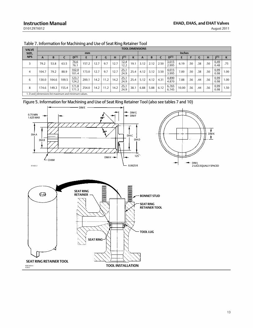
Trim removal and replacement requires the use of a seat ring retainer tool (figure 5). If specifically ordered, a tool issupplied with a valve body; but the tool can also be ordered separately by referencing the tool part number in the PartsList. If desired, a tool can also bemachined for a valve body of specific size and valve class using the dimensions shownin figure 5. Machine the tool from amaterial listed in figure 5 or from amaterial with a yield strength of at least 827MPa (120,000 psi). Using a tool of lower strengthmaterial may result in damage to the seat ring retainer or valve bodythreads.
1. Remove the actuator and bonnet by following steps 1 through 4 of the Replacing Packing procedure. Observe allwarnings and cautions.
2. Lift the valve stem and attached valve plug out of the valve body. If the valve plug is to be reused, tape or otherwiseprotect the valve plug stem and the valve plug seating surface to prevent scratches.
3. Lift out the cage (key 2) and the top and bottom cage gaskets (key 5). For a valve body with a Cavitrol III two- orthree-stage cage, also remove the O-ring (key 36) that fits between the cage and the seat ring (key 31).
4. Use the seat ring retainer tool (figure 5) to remove the seat ring retainer (key 32) as follows:
a. Insert the tool into the valve body. Be certain the tool lugs are engaged in the corresponding recesses in theretainer.
b. Use a power torque wrench or driver having torque capabilities equal to or greater than those shown in table 8.Connect the torque wrench to an extension if necessary. The tool or extensionmust snugly fit the square hole inthe seat ring retainer tool. Refer to figure 5 for square hole sizes.
c. Insert the tool or extension into the square hole in the seat ring retainer tool.
d. Use the bonnet studs (key 10) to prevent a power torque wrench from rotating.
CAUTION
Hold the torquewrench or driver at right angles to the seat ring retainer when applying torque. Tilting the tool orextensionwhile applying torquemay cause the lugs on the seat ring retainer tool to suddenly disengage from the recessesin the retainer, damaging the retainer and seat ring.
InstructionManualD101297X012
EHAD, EHAS, and EHAT ValvesAugust 2011
12
e. Unscrew and remove the seat ring retainer.
5. Remove the seat ring (key 31) and the seat ring gasket or O-ring (key 33).
6. Refer to the Valve PlugMaintenance procedure or to the Lapping Seats procedure.
Valve PlugMaintenanceKey numbers used in this procedure are shown in figure 15 for the EHAD valve body, in figure 16 for the EHAS valvebody, and in figure 17 for the EHAT valve body.
1. With the valve plug (key 3A) removed according to the Trim Removal procedure, proceed as appropriate:
For the EHAD valve body, the piston rings (key 9) are each in two sections; remove the sections from the grooves in thevalve plug.
For the EHAS valve body, proceed to step 2.
For the EHAT valve body, work the retaining ring (key 7) off the valve plug with a screwdriver. Carefully slide thebackup ring and seal ring (keys 8 and 9) off the valve plug. For an NPS 8 valve with a level DWhisper Trim III cage, alsoremove the piston ring (key 41) from the grooves in the valve plug.
2. To replace the valve plug stem (key 3B), drive out the pin (key 3C), and unscrew the stem from the valve plug.
CAUTION
Never reuse an old stemwith a new valve plug. Using an old stemwith a new plug requires drilling a new pin hole in thestem. This weakens the stem andmay cause the stem to fail in service. If a new valve plug is required, always order a valveplug, stem, and pin as an assembly. Specify the correct part number of each of the three parts, but state that the parts arebeing ordered as an assembly.
A used valve plugmay be reusedwith a new stem. An exception is the Cavitrol III plug/stem assemblywhichmust beordered and replaced as a unit.
3. Thread the new stem into the valve plug and tighten it to the appropriate torque value given in table 9. Using thevalve plug pin hole as a guide, drill the pin hole through the stem. Refer to table 9 for drill sizes.
4. Drive in the pin to lock the assembly.
5. If it is necessary to lap the seating surfaces, complete the Lapping Seats procedure before installing the EHADpiston rings or the EHAT seal ring. The Trim Replacement procedure provides piston ring and seal ring installationinstructions and valve body reassembly instructions.
Lapping SeatsKey numbers referenced in this procedure are shown in figure 15 for the EHAD valve body, in figure 16 for the EHASvalve body, and in figure 17 for the EHAT valve body unless otherwise indicated.
InstructionManualD101297X012
EHAD, EHAS, and EHAT ValvesAugust 2011
13
Table 7. Information for Machining and Use of Seat Ring Retainer ToolVALVESIZE,NPS
TOOL DIMENSIONS
mm Inches
A B C D(1) E F G H J(1) K A B C D(1) E F G H J(1) K
3 79.2 53.8 63.576.676.1
157.2 12.7 9.7 12.712.412.2
19.1 3.12 2.12 2.503.0152.995
6.19 .50 .38 .500.490.48
.75
4 104.7 79.2 88.9102.0101.4
173.0 12.7 9.7 12.725.124.9
25.4 4.12 3.12 3.504.0153.995
7.00 .50 .38 .500.990.98
1.00
6 130.0 104.6 109.5123.7124.2
200.1 14.2 11.2 14.225.124.9
25.4 5.12 4.12 4.314.8904.870
7.88 .56 .44 .560.990.98
1.00
8 174.6 149.3 155.4171.8171.3
254.0 14.2 11.2 14.225.124.9
38.1 6.88 5.88 6.126.7656.745
10.00 .56 .44 .560.990.98
1.50
1. D and J dimensions list maximum andminimum values.
Figure 5. Information for Machining and Use of Seat Ring Retainer Tool (also see tables 7 and 10)DIM E
DIM GDIM F
0.0625 R
DIA D
DIA C
125DIM HCHAM
DIA A
DIA B
0.75 MIN1.625MAX
DIM J2 LUGS EQUALLY SPACED
DIM K
B1465-2
SEAT RINGRETAINER BONNET STUD
SEAT RINGRETAINER TOOL
TOOL LUG
SEAT RING
SEAT RING RETAINER TOOLTOOL INSTALLATION40B7469-A
A3603

InstructionManualD101297X012
EHAD, EHAS, and EHAT ValvesAugust 2011
14
Table 8. Recommended Torque for Installing Seat Ring Retainer
VALVESIZE,NPS
TORQUE
For All Valves withGasketed Seat RingConstruction Except
ThosewithCavitrol III Cage
For All Valves withO-Ring Seat Ring
Construction(1) or forNACEMR0175-2002
For Valvewith 2-StageCavitrol III Cage andGasketed Seat RingConstruction
For Valvewith 3-StageCavitrol III Cage andGasketed Seat RingConstruction
NSm LbfSFt NSm LbfSFt NSm LbfSFt NSm LbfSFt
3 1187 875 136 100 881 650 678 500
4 2203 1625 271 200 1491 1100 1356 1000
6 3118 2300 373 275 2712 2000 2373 1750
8 6780 5000 780 575 6101 4500 5423 40001. Includes valves with Cavitrol III trim.
Table 9. Valve Stem Connection Torque and Drill Size for Pin Hole
VALVE SIZE,NPS
VALVE STEMDIAMETER VALVE
VALVE STEMCONNECTION TORQUE(MINIMUM -MAXIMUM)
DRILL SIZEFOR PIN
mm Inches NSm LbfSFt
3
12.7 1/2 EHAD, EHAS, EHAT 81 - 115 60 - 85 0.125
19.1 3/4EHAS 237 - 339 175 - 250 0.1875
EHAD, EHAT 237 - 339 175 - 250 0.125
25.4 1 EHAS 420 - 481 310 - 355 0.25
4
12.7 1/2 EHAD, EHAS, EHAT 81 - 115 60 - 85 0.125
19.1 3/4 EHAD, EHAS, EHAT 237 - 339 175 - 250 0.1875
25.4 1EHAS 420 - 481 310 - 355 0.25
EHAD, EHAT 420 - 481 310 - 355 0.25
619.1 3/4 EHAD, EHAS, EHAT 237 - 339 175 - 250 0.1875
25.4 1 EHAD, EHAS, EHAT 420 - 481 310 - 355 0.25
8
19.1 3/4 EHAD, EHAS, EHAT 237 - 339 175 - 250 0.1875
25.4 1 EHAD, EHAS, EHAT 420 - 481 310 - 355 0.25
31.8 1-1/4 EHAD, EHAS, EHAT 827 - 908 610 - 670 0.25
50.8 2 EHAD, EHAT Contact factory for torque values andinstallation procedure
0.375
Table 10. Materials for Machining Tool (see figure 5)RecommendedMaterials MinimumRockwell Hardness
416 stainless steel17-4PH stainless steel
4100 Series heat-treated steel
283631
Seating surfaces of the valve plug (key 3A) and the seat ring (key 31) can be lapped for improved shutoff. Use a goodquality lapping compound of amixture of 280 to 600 grit. Apply compound to the bottom of the valve plug. Use thefollowing procedure to lap the seating surfaces.
1. Install the following parts according to the instructions presented in the Trim Replacement procedure: seat ringgasket or O-ring (key 33), seat ring (key 31), seat ring retainer (key 32), cage (key 2), cage gaskets (key 5), and, ifused, the O-ring (key 36).
2. Proceed as appropriate:
For an EHAD or EHAT valve body, install the valve plug and stem assembly (keys 3A and 3B)–without piston rings (key9 and, if used, key 41) or seal ring (key 9)–into the cage.
For an EHAS valve body, install the valve plug and stem assembly (keys 3A and 3B) into the cage.
3. Install the bonnet (key 1, figure 13) over the valve stem, and secure the bonnet with four of the bonnet stud nuts(key 11).

InstructionManualD101297X012
EHAD, EHAS, and EHAT ValvesAugust 2011
15
4. Attach a handle, such as a piece of strap iron secured by stem locknuts, to the valve stem. Rotate the handlealternately in each direction to lap the seats.
Table 11. Seat Ring and Seat Ring Retainer LubricantsValveMaterial Seat RingMaterial Lubricant
WCC,WC9, C5, or LCC steelS41600 (416 stainless steel) Lithium grease, dry film lubricant, or anti-seize lubricant
R30006 (Alloy 6) Anti-seize lubricant
CF8M (316 stainless steel) R30006 Dry film lubricant or anti-seize lubricant
Note
To preserve the effects of lapping, do not change either the position of the seat ring in the valve body cavity or the position of thecage on the seat ring after lapping the seating surfaces. If possible, clean the parts without disturbing their positions. If the partsmust be removed for cleaning, return them to the original positions.
5. After lapping, again disassemble as necessary, clean the seating surfaces, reassemble, and test for shutoff. Repeatthe lapping procedure if necessary.
Trim ReplacementAfter all trimmaintenance has been completed, reassemble the valve body by following the numbered steps below. Becertain that all gasketed surfaces have been well cleaned. Key numbers referenced in this procedure are shown infigure 15 for the EHAD valve, in figure 16 for the EHAS valve, and/or in figure 17 for the EHAT valve.
CAUTION
Thoroughly clean the seat ring (key 31), seat ring retainer (key 32), and the retainer threads in the valve bodywith agood-quality degreaser. Also clean all cage gasket surfaces. Residual gasketmaterial must be removed from the cagegasket surfaces and, in gasketed seat ring constructions, from the serrated valve body and seat ring gasket surfaces. If theserrations are scored or damaged during this process, smooth them by hand sandingwith 360 grit paper using long,sweeping strokes. Failure to remove the residual gasketmaterial and/or burrs from the seat ring, cage, and valve bodygasket surfaces will result in leakage.
Thoroughly lubricate the surfaces indicated in figure 6with the appropriate lubricant shown in table 11. Be certain tolubricate themating surfaces of both parts involved (i.e., lubricate the threads on the seat ring retainer and the threads inthe valve body; lubricate themating surfaces of the seat ring retainer and seat ring).
Failure to lubricate as describedmay cause galling and improper loading of the seat ring gasket or O-ring (key 33) thatmayresult in leakage.
1. For a gasketed seat ring construction, install the seat ring gasket (key 33) into the valve body. For an O-ring seatring construction, install the O-ring (key 33) into the groove on the underside of the seat ring (key 31). Install theseat ring (key 31). Screw in the seat ring retainer (key 32). Use the seat ring retainer tool (figure 5) to tighten theseat ring retainer as follows:
a. Insert the tool into the valve body. Be certain the tool lugs are engaged in the corresponding recesses in theretainer.
b. Use a power torque wrench or driver having torque capabilities equal to or greater than those shown in table 8.Connect the torque tool to an extension if necessary. The tool or extensionmust snugly fit the square hole in theseat ring retainer tool. Refer to figure 5 for square hole sizes.
c. Insert the tool or extension into the square hole in the seat ring retainer tool.

InstructionManualD101297X012
EHAD, EHAS, and EHAT ValvesAugust 2011
16
d. Use the bonnet studs (key 10) to prevent a power torque wrench from rotating.
Figure 6. Trim Surfaces Requiring LubricationSEAT RING RETAINER
A3583
SEAT RING GASKET ORO-RING
SEATRING
VALVE BODYLUBRICATION REQUIRED
1
1
1
CAUTION
Hold the torquewrench at right angles to the seat ring retainer when applying torque. Tilting the tool and extensionwhileapplying torquemay cause the lugs on the seat ring retainer tool to suddenly disengage from the recesses in the retainer,damaging the retainer and seat ring.
e. Tighten the seat ring retainer to the torque shown in table 8.
Note
Some cages have one large window and several small windows. In step 2, install a cage that has different size windows so that thelargest window faces toward the process outlet for a flow-down and toward the process inlet for a flow-up valve body. Though itmay not be possible to align the large window directly opposite the inlet or outlet, orient the window in the appropriate directionas much as possible. Incorrect orientation of cage windows causes a reduction of capacity.
2. Proceed as appropriate:
For a valve with a Cavitrol III cage, slide the O-ring (key 36) over the seat ring (key 31) and against the shoulder in theouter diameter of the seat ring. Install the lower cage gasket (key 5) between the valve body and cage (key 2), andinstall the cage. Be certain the lugs on the bottom of the cage engage the corresponding slots in the seat ring retainer.

InstructionManualD101297X012
EHAD, EHAS, and EHAT ValvesAugust 2011
17
For all other valves, install the lower cage gasket (key 5) between the valve body and cage (key 2), and install the cage.Be certain the lugs on the bottom of the cage engage the corresponding slots in the seat ring retainer.
Note
Rotate the cage clockwise by hand asmuch as possible once the cage lugs engage the slots in the seat ring retainer. Failure to dosomay result in leakage at the seat ring-to-valve body seal.
3. To install the piston rings (key 9 and, if used, key 41) or seal ring (key 9), proceed as appropriate:
For an EHAD valve body (figure 15), if it is necessary to install new piston rings, the replacement piston rings will arrivein one piece. Use a vise with smooth or taped jaws to break a replacement piston ring into halves. Place the new ring inthe vise so that the jaws compress the ring into an oval. Compress the ring slowly until the ring snaps on both sides. Ifone side snaps first, do not try to tear or cut the other side. Instead, keep compressing until the other side snaps. Thepiston ring can also be fractured by scoring and snapping over a hard surface such as a table edge. Sawing or cutting isnot recommended.
Remove any protective tape or covering from the valve plug and stem assembly, and set it on a protective surface.Then, place the piston ring in the piston ring groove with the fractured endsmatched.
Figure 7. Fisher EHADwith C-seal Trim
FLOWDOWN FLOWUP
VIEWA
37B1047-A
A
For an EHAT valve body (figure 17), install the seal ring (key 9) onto the valve plug (key 3A). Install the ring with theopen side facing the seat ring end of the valve plug for flow-down applications (view A of figure 17) or with the openside facing the valve plug stem end of the valve plug for flow-up applications. Slide the backup ring (key 8) onto thevalve plug and secure with the retaining ring (key 7). For an NPS 8 valve with a level DWhisper Trim III cage, reinstallthe piston ring (key 41) following the instructions given in the paragraph immediately preceding.
4. Install the valve plug into the cage.
5. Install the top cage gasket (key 5) on the cage.
InstructionManualD101297X012
EHAD, EHAS, and EHAT ValvesAugust 2011
18
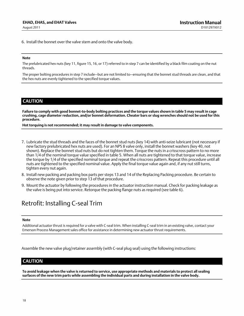
6. Install the bonnet over the valve stem and onto the valve body.
Note
The prelubricated hex nuts (key 11, figure 15, 16, or 17) referred to in step 7 can be identified by a black film coating on the nutthreads.
The proper bolting procedures in step 7 include–but are not limited to–ensuring that the bonnet stud threads are clean, and thatthe hex nuts are evenly tightened to the specified torque values.
CAUTION
Failure to complywith good bonnet-to-body bolting practices and the torque values shown in table 5may result in cagecrushing, cage diameter reduction, and/or bonnet deformation. Cheater bars or slugwrenches should not be used for thisprocedure.
Hot torquing is not recommended; it may result in damage to valve components.
7. Lubricate the stud threads and the faces of the bonnet stud nuts (key 14) with anti-seize lubricant (not necessary ifnew factory prelubricated hex nuts are used). For an NPS 8 valve only, install the bonnet washers (key 40, notshown). Replace the bonnet stud nuts but do not tighten them. Torque the nuts in a crisscross pattern to nomorethan 1/4 of the nominal torque value specified in table 5.When all nuts are tightened to that torque value, increasethe torque by 1/4 of the specified nominal torque and repeat the crisscross pattern. Repeat this procedure until allnuts are tightened to the specified nominal value. Apply the final torque value again and, if any nut still turns,tighten every nut again.
8. Install new packing and packing box parts per steps 13 and 14 of the Replacing Packing procedure. Be certain toobserve the note given prior to step 13 of that procedure.
9. Mount the actuator by following the procedures in the actuator instructionmanual. Check for packing leakage asthe valve is being put into service. Retorque the packing flange nuts as required (see table 6).
Retrofit: Installing C-seal Trim
Note
Additional actuator thrust is required for a valve with C-seal trim. When installing C-seal trim in an existing valve, contact yourEmerson Process Management sales office for assistance in determining new actuator thrust requirements.
Assemble the new valve plug/retainer assembly (with C-seal plug seal) using the following instructions:
CAUTION
To avoid leakagewhen the valve is returned to service, use appropriatemethods andmaterials to protect all sealingsurfaces of the new trim parts while assembling the individual parts and during installation in the valve body.

InstructionManualD101297X012
EHAD, EHAS, and EHAT ValvesAugust 2011
19
Table 12. C-seal Plug Seal Installation Tool DimensionsFOR VALVEPLUGSFITTINGPORT SIZE(Inches)
DIMENSIONS,mm(See Drawing Below) Part Number
(To OrderA Tool)A B C D E F G H
2.875 82.5552.324 -52.578
4.978 - 5.029 3.708 - 3.759 41.14852.680 -52.781
55.118 -55.626
70.891 - 71.044 24B9816X012
3.4375 101.658.674 -58.928
4.978 - 5.029 3.708 - 3.759 50.861.011 -61.112
63.449 -63.957
85.166 - 85.319 24B5612X012
3.625 104.39465.024 -65.278
4.978 - 5.029 3.708 - 3.759 50.868.936 -69.037
71.374 -71.882
89.941 - 90.094 24B3630X012
4.375 125.98483.439 -83.693
4.978 - 5.029 3.708 - 3.759 50.887.351 -87.452
89.789 -90.297
108.991 - 109.144 24B3635X012
5.375 142.748100.076 -100.33
4.978 - 5.029 3.708 - 3.759 45.974103.835 -103.937
106.274 -106.782
128.219 - 128.372 23B9193X012
7 184.15141.376 -141.630
4.978 - 5.029 3.708 - 3.759 60.198145.136 -145.237
147.574 -148.082
169.520 - 169.672 23B9180X012
8 209.55166.776 -167.030
4.978 - 5.029 3.708 - 3.759 55.88170.536 -170.637
172.974 -173.482
194.920 - 195.072 24B9856X012
FOR VALVEPLUGSFITTINGPORT SIZE(Inches)
DIMENSIONS, INCHES(See Drawing Below) Part Number
(To OrderA Tool)A B C D E F G H
2.875 3.25 2.060 - 2.070 0.196 - 0.198 0.146 - 0.148 1.62 2.074 - 2.078 2.170 - 2.190 2.791 - 2.797 24B9816X012
3.4375 4.00 2.310 - 2.320 0.196 - 0.198 0.146 - 0.148 2.00 2.402 - 2.406 2.498 - 2.518 3.353 - 3.359 24B5612X012
3.625 4.11 2.560 - 2.570 0.196 - 0.198 0.146 - 0.148 2.00 2.714 - 2.718 2.810 - 2.830 3.541 - 3.547 24B3630X012
4.375 4.96 3.285 - 3.295 0.196 - 0.198 0.146 - 0.148 2.00 3.439 - 3.443 3.535 - 3.555 4.291 - 4.297 24B3635X012
5.375 5.62 3.940 - 3.950 0.196 - 0.198 0.146 - 0.148 1.81 4.088 - 4.092 4.184 - 4.204 5.048 - 5.054 23B9193X012
7 7.25 5.566 - 5.576 0.196 - 0.198 0.146 - 0.148 2.37 5.714 - 5.718 5.810 - 5.830 6.674 - 6.680 23B9180X012
8 8.25 6.566 - 6.576 0.196 - 0.198 0.146 - 0.148 2.20 6.714 - 6.718 6.810 - 6.830 7.674 - 7.680 24B9856X012
Figure 8. C-seal Plug Seal Installation Tool
45 X 1.524 (0.06)
A
B
8 - 9
DC
F
G
H
E
BREAK SHARPCORNER45 X 0.254 (0.01)MAX
45 X 0.508 (0.02)
A6777
mm (inch)
InstructionManualD101297X012
EHAD, EHAS, and EHAT ValvesAugust 2011
20
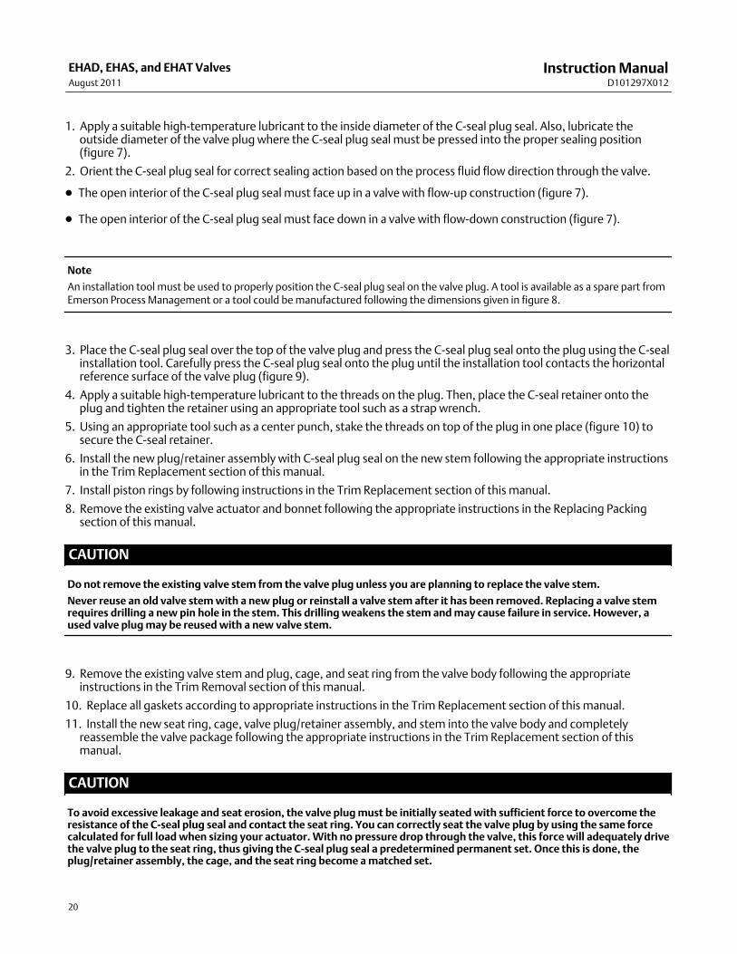
1. Apply a suitable high-temperature lubricant to the inside diameter of the C-seal plug seal. Also, lubricate theoutside diameter of the valve plug where the C-seal plug seal must be pressed into the proper sealing position(figure 7).
2. Orient the C-seal plug seal for correct sealing action based on the process fluid flow direction through the valve.
D The open interior of the C-seal plug seal must face up in a valve with flow-up construction (figure 7).
D The open interior of the C-seal plug seal must face down in a valve with flow-down construction (figure 7).
Note
An installation tool must be used to properly position the C-seal plug seal on the valve plug. A tool is available as a spare part fromEmerson Process Management or a tool could bemanufactured following the dimensions given in figure 8.
3. Place the C-seal plug seal over the top of the valve plug and press the C-seal plug seal onto the plug using the C-sealinstallation tool. Carefully press the C-seal plug seal onto the plug until the installation tool contacts the horizontalreference surface of the valve plug (figure 9).
4. Apply a suitable high-temperature lubricant to the threads on the plug. Then, place the C-seal retainer onto theplug and tighten the retainer using an appropriate tool such as a strap wrench.
5. Using an appropriate tool such as a center punch, stake the threads on top of the plug in one place (figure 10) tosecure the C-seal retainer.
6. Install the new plug/retainer assembly with C-seal plug seal on the new stem following the appropriate instructionsin the Trim Replacement section of this manual.
7. Install piston rings by following instructions in the Trim Replacement section of this manual.
8. Remove the existing valve actuator and bonnet following the appropriate instructions in the Replacing Packingsection of this manual.
CAUTION
Do not remove the existing valve stem from the valve plug unless you are planning to replace the valve stem.
Never reuse an old valve stemwith a new plug or reinstall a valve stem after it has been removed. Replacing a valve stemrequires drilling a new pin hole in the stem. This drillingweakens the stem andmay cause failure in service. However, aused valve plugmay be reusedwith a new valve stem.
9. Remove the existing valve stem and plug, cage, and seat ring from the valve body following the appropriateinstructions in the Trim Removal section of this manual.
10. Replace all gaskets according to appropriate instructions in the Trim Replacement section of this manual.
11. Install the new seat ring, cage, valve plug/retainer assembly, and stem into the valve body and completelyreassemble the valve package following the appropriate instructions in the Trim Replacement section of thismanual.
CAUTION
To avoid excessive leakage and seat erosion, the valve plugmust be initially seatedwith sufficient force to overcome theresistance of the C-seal plug seal and contact the seat ring. You can correctly seat the valve plug by using the same forcecalculated for full loadwhen sizing your actuator.With no pressure drop through the valve, this forcewill adequately drivethe valve plug to the seat ring, thus giving the C-seal plug seal a predetermined permanent set. Once this is done, theplug/retainer assembly, the cage, and the seat ring become amatched set.

InstructionManualD101297X012
EHAD, EHAS, and EHAT ValvesAugust 2011
21
With full actuator force applied and the valve plug fully seated, align the actuator travel indicator scalewith the lower endof valve travel. Refer to the appropriate actuator instructionmanual for information on this procedure.
Replacement of Installed C-seal Trim
Trim Removal (C-seal Constructions)1. Remove the valve actuator and bonnet following the appropriate instructions in the Replacing Packing section ofthis manual.
Figure 9. Installing the C-seal Plug Seal Using the Installation Tool
NOTE:PRESS INSTALLATION TOOL OVER VALVE PLUG UNTIL THE TOOL CONTACTS THEHORIZONTAL REFERENCE SURFACE OF THE VALVE PLUG.
C-sealMETALPLUGSEAL
INSTALLATIONTOOL
VALVEPLUG
HORIZONTALREFERENCESURFACE
FLOWDOWNA6778
CAUTION
To avoid leakagewhen the valve is returned to service, use appropriatemethods andmaterials to protect all sealingsurfaces of the trim parts duringmaintenance.Use cautionwhen removing piston ring(s) and C-seal plug seal to avoid scratching any sealing surface.
CAUTION
Do not remove the valve stem from the plug/retainer assembly unless you are planning to replace the valve stem.Never reuse an old valve stemwith a new plug or reinstall a valve stem after it has been removed. Replacing a valve stemrequires drilling a new pin hole in the stem. This drillingweakens the stem andmay cause failure in service. However, aused valve plugmay be reusedwith a new valve stem.

InstructionManualD101297X012
EHAD, EHAS, and EHAT ValvesAugust 2011
22
Figure 10. Stake the Threads of the C-seal Retainer
C-sealMETALPLUGSEAL VALVE
PLUG
FLOWDOWN
PISTONRING
RETAINER
DEFORMTHREAD TOSTAKE C-seal RETAINER
A6779
2. Remove the plug/retainer assembly (with C-seal plug seal), cage, and seat ring from the valve body following theappropriate instructions in the Trim Removal section of this manual.
3. Locate the staked thread on top of the valve plug (figure 10). The staked thread secures the retainer. Use a drill witha 1/8 inch bit to drill out the staked area of the thread. Drill approximately 1/8 inch into themetal to remove thestaking.
4. Locate the break between sections of the piston ring(s). Using an appropriate tool such as a flat-blade screwdriver,carefully pry out the piston ring(s) from the groove(s) in the C-seal retainer.
5. After removing the piston ring(s), locate the 1/4-inch diameter hole in the groove. In a retainer with two piston ringgrooves, the hole will be found in the upper groove.
6. Select an appropriate tool such as a punch and place the tip of the tool into the hole with the body of the tool heldtangent to the outside diameter of the retainer. Strike the tool with a hammer to rotate the retainer and free it fromthe valve plug. Remove the retainer from the plug.
7. Use an appropriate tool such as a flat-blade screwdriver to pry the C-seal plug seal off the plug. Use caution to avoidscratches or other damage to the sealing surfaces where the C-seal plug seal makes contact with the valve plug(figure 11).

InstructionManualD101297X012
EHAD, EHAS, and EHAT ValvesAugust 2011
23
Figure 11. Lower (Valve Plug to Seat Ring) and Upper (C-seal Plug Seal to Cage) Seating Surfaces
C-seal METALPLUG SEAL
RETAINER
CAGEVALVE PLUG
NOTE:UPPER SEATING SURFACE IS THE AREAOF CONTACT BETWEEN THE C-seal METAL PLUG SEAL AND THE CAGE.
PLUG
CAGE
SEATRING
UPPER SEATING SURFACE
LOWER SEATING SURFACEA6780
1
1
8. Inspect the lower seating surface where the valve plug contacts the seat ring for wear or damage which wouldprevent proper operation of the valve. Also, inspect the upper seating surface inside the cage where the C-seal plugseal contacts the cage, and inspect the sealing surface where the C-seal plug seal makes contact with the plug(figure 11).
9. Replace or repair trim parts according to the following procedure for LappingMetal Seats, RemachiningMetalSeats, or other valve plugmaintenance procedures as appropriate.
Lapping Metal Seats (C-seal Constructions)Before installing a new C-seal plug seal, lap the lower seating surface (valve plug to seat ring, figure 11) followingappropriate procedures in the Lapping Seats section of this manual.
Remachining Metal Seats (C-seal Constructions)See figure 12. A valve plug with a C-seal metal plug seal features two seating surfaces. One seating surface is foundwhere the valve plug contacts the seat ring. The second seating surface is found where the C-seal plug seal contactsthe upper seating surface in the cage. If youmachine the seats on the seat ring and/or plug, youmustmachine anequal dimension from the seating area in the cage.
CAUTION
Ifmetal is removed from the seat ring and plug and a corresponding amount is not removed from the cage seating area, theC-seal plug seal will be crushed as the valve closes and the C-seal retainerwill strike the seating area of the cage, preventingthe valve from closing.

InstructionManualD101297X012
EHAD, EHAS, and EHAT ValvesAugust 2011
24
Figure 12. Example of Machining the Lower (Valve Plug to Seat Ring) and Upper (C-seal Plug Seal to Cage) SeatingSurfaces
UPPER SEATING SURFACE
0.508 (0.020)(4)
0.254 (0.010)(4)
0.254 (0.010)(4)
C-sealRETAINER
MACHININGOF THE UPPERSEATING SURFACEMUSTEQUAL THE TOTAL MACHINING OFTHE LOWER SEATING SURFACE(PLUGPLUSSEATRING). IFNOT,THERETAINER MAY STRIKE THE UPPERSEATING SURFACE BEFORE THEVALVE PLUG PROPERLY SEATS ONTHE LOWER SEATING SURFACE.
LOWER SEATING SURFACE
REMOVALOF 0.254mm (0.010 inch) FROM THE VALVE PLUGPLUS REMOVALOF 0.254mm (0.010 inch) FROMTHE SEAT RING
REMOVAL OF 0.508mm (0.020 inch) FROM THEUPPER SEATING SURFACE IN THE CAGE
4. THESE VALUES ARE FOR EXAMPLE ONLY. REMOVE ONLY THEMINIMUMAMOUNT OFMATERIAL REQUIRED TO REFURBISH THE SEATS.
SEATRING
PLUG
CAGE
A6781 / IL
1
3
2
123
NOTE:
MUST EQUAL
mm (inch)
Trim Replacement (C-seal Constructions)1. Apply a suitable high-temperature lubricant to the inside diameter of the C-seal plug seal. Also, lubricate theoutside diameter of the valve plug where the C-seal plug seal must be pressed into the proper sealing position(figure 7).
2. Orient the C-seal plug seal for correct sealing action based on the process fluid flow direction through the valve.
D The open interior of the C-seal plug seal must face up in a valve with flow-up construction (figure 7).
D The open interior of the C-seal plug seal must face down in a valve with flow-down construction (figure 7).
Note
An installation tool must be used to properly position the C-seal plug seal on the valve plug. A tool is available as a spare part fromEmerson Process Management or a tool could bemanufactured following the dimensions given in figure 8.
3. Place the C-seal plug seal over the top of the valve plug and press it onto the plug using the installation tool.Carefully press the C-seal plug seal onto the plug until the installation tool contacts the horizontal reference surfaceof the valve plug (figure 9).
4. Apply a suitable high-temperature lubricant to the threads on the plug. Then, place the C-seal retainer onto theplug and tighten the retainer using an appropriate tool such as a strap wrench.

InstructionManualD101297X012
EHAD, EHAS, and EHAT ValvesAugust 2011
25
5. Using an appropriate tool such as a center punch, stake the threads on top of the plug in one place (figure 10) tosecure the C-seal retainer.
6. Replace the piston ring(s) following instructions in the Trim Replacement section of this manual.
7. Return the seat ring, cage, plug/retainer assembly, and stem to the valve body and completely reassemble the valvepackage following the appropriate instructions in the Trim Replacement section of this manual.
CAUTION
To avoid excessive leakage and seat erosion, the valve plugmust be initially seatedwith sufficient force to overcome theresistance of the C-seal plug seal and contact the seat ring. You can correctly seat the valve plug by using the same forcecalculated for full loadwhen sizing your actuator.With no pressure drop through the valve, this forcewill adequately drivethe valve plug to the seat ring, thus giving the C-seal plug seal a predetermined permanent set. Once this is done, theplug/retainer assembly, the cage, and the seat ring become amatched set.
With full actuator force applied and the valve plug fully seated, align the actuator travel indicator scalewith the lower endof valve travel. Refer to the appropriate actuator instructionmanual for information on this procedure.
Parts OrderingEach valve body-bonnet assembly is assigned a serial number, which can be found on the valve body. This samenumber also appears on the nameplate. Refer to the number when contacting your Emerson Process Managementsales office for technical assistance or when ordering replacement parts.
When ordering replacement parts, also be sure to include the 11-character part number for each part required fromthe following parts list.
WARNING
Use only genuine Fisher replacement parts. Components that are not supplied by Emerson ProcessManagement shouldnot, under any circumstances, be used in any Fisher valve, because theywill void yourwarranty, might adversely affect theperformance of the valve, and could give rise to personal injury and property damage.

InstructionManualD101297X012
EHAD, EHAS, and EHAT ValvesAugust 2011
26
Figure 13. Bonnet Assemblies
71mm (2-3/16 INCH) YOKE BOSS BONNETWITH SINGLE ARRANGEMENT PTFE PACKING
56A5372-EA2699-2
DETAIL OF BAFFLE AND RETAINING RINGUSED IN EXTENSION BONNET
DETAIL OF 127mm (5-INCH) YOKE BOSS ACTUATORBOLTING FORNPS 3, 4, 6 & 8 EHA SERIES VALVE BODIES
18A8557-A
35A3976-A

InstructionManualD101297X012
EHAD, EHAS, and EHAT ValvesAugust 2011
27
Figure 14. Live-Loaded Packing
39B4153-A
A6297-1
Typical HIGH-SEAL ULF Packing System Typical ENVIRO-SEAL Packing Systemwith PTFE Packing
Typical ENVIRO-SEAL Packing Systemwith Graphite ULF Packing
Typical ENVIRO-SEAL Packing Systemwith Duplex Packing
200
212
201
215
216
207
209
211
217
207
207
207
214
213
A672239B4612/A

InstructionManualD101297X012
EHAD, EHAS, and EHAT ValvesAugust 2011
28
Parts KitsPacking Kits (non live-loaded)
StemDiameter, mm (Inches)Yoke Boss Diameter, mm (Inches)
12.7 (1/2)71 (2-13/16)
19.1 (3/4)90 (3-9/16)
PTFE (Contains keys 6, 8, 10, 11, and 12) RPACKX00022 RPACKX00032
Double PTFE (Contains keys 8, 11, and 12) RPACKX00052 RPACKX00062
PTFE/Composition (Contains keys 7, 8, 11 and 12) RPACKX00082 RPACKX00092
Single Graphite Ribbon/Filament [Contains keys 7 (ribbon rings), 7 (filament rings), 8, and 11] RPACKX00112 RPACKX00122
Single Graphite Ribbon/Filament [Contains keys 7 (ribbon rings) and 7 (filament rings)] RPACKX00142 RPACKX00152
Double Graphite Ribbon/Filament [Contains keys 7 (ribbon rings), 7 (filament rings), 8, and 11] RPACKX00172 RPACKX00182
Repair Kits (ENVIRO-SEAL)StemDiameter, mm (Inches)
Yoke Boss Diameter, mm (Inches)12.7 (1/2)71 (2-13/16)
19.1 (3/4)90 (3-9/16)
25.4 (1)127 (5)
31.8 (1-1/4)127 (5, 5H)
Double PTFE (Contains keys 214, 215, 218) RPACKX00202 RPACKX00212 RPACKX00222 RPACKX00232
Graphite ULF (Contains keys 207, 208, 209, 210, 214) RPACKX00602 RPACKX00612 RPACKX00622 RPACKX00632
Duplex (Contains keys 207, 209, 214, 215) RPACKX00302 RPACKX00312 RPACKX00322 RPACKX00332
Retrofit Kits (ENVIRO-SEAL)StemDiameter, mm (Inches)
Yoke Boss Diameter, mm (Inches)12.7 (1/2)71 (2-13/16)
19.1 (3/4)90 (3-9/16)
25.4 (1)127 (5)
31.8 (1-1/4)127 (5, 5H)
Double PTFE (Contains keys 200, 201, 211, 212,214, 215, 216, 217, 218, tag, cable tie)
RPACKXRT022 RPACKXRT032 RPACKXRT042 RPACKXRT052
Graphite ULF (Contains keys 200, 201, 207, 208, 209, 210, 211,212, 214, 217, tag, cable tie)
RPACKXRT272 RPACKXRT282 RPACKXRT292 RPACKXRT302
Duplex (Contains keys 200, 201, 207, 209, 211, 212, 214, 215,216, 217, tag, cable tie)
RPACKXRT222 RPACKXRT232 RPACKXRT242 RPACKXRT252
Parts List
NotePart numbers are shown for recommended spares only. For partnumbers not shown, contact your Emerson Process Management salesoffice.
Bonnet Assembly (figure 13)Key Description Part Number
1 BonnetIf you need a bonnet as a replacement part, order by valve sizeand stem diameter, serial number, and desiredmaterial
2 Baffle, for use with extension bonnet only3 Packing Flange4 Packing Flange Stud (2 req'd)5 Packing Flange Nut (2 req'd)6* Packing Set See table 14
Key Description Part Number
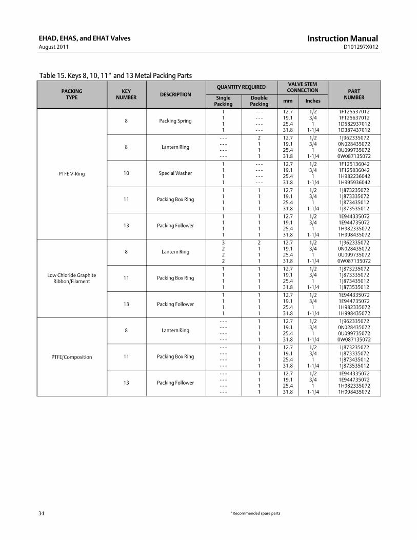
7* Packing Ring, PTFE See table 147* Packing Ring, graphite ribbon See table 147* Packing Ring, graphite filament See table 148 Packing Spring or Lantern Ring,
316 stainless steel See table 1510 Special Washer, 316 stainless steel See table 1511* Packing Box Ring, 316 stainless steel See table 1512* UpperWiper, felt See table 1413 Packing Follower, 316 stainless steel See table 1514 Pipe Plug14 Lubricator, steel14 Lubricator/Isolating Valve15 Yoke Locknut, steel25 Actuator Mounting Stud, steel (8 req'd)26 Actuator Stud Nut (8 req'd)35 Retaining Ring, for use with extension bonnet only
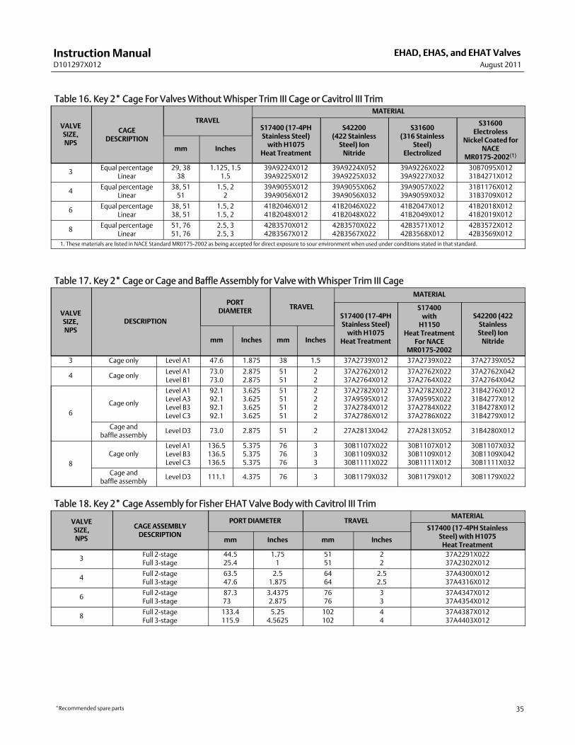
Valve (figures 15-17)2* Cage See tables 16-183A* Valve Plug, Valve Plug/Stem, or Valve/Plug/
Ring Assembly See tables 19-243B* Valve Plug Stem See tables 25-273C* Pin See table 28
*Recommended spare parts

InstructionManualD101297X012
EHAD, EHAS, and EHAT ValvesAugust 2011
29
Key Description Part Number
5* Cage Gasket (2 req'd) See table 297* Retaining Ring (for EHAT only)
302 stainless steelFor use with 25.4mm (1-inch) portdiameter 11A3405X022For use with 44.5mm (1.75 inch)port diameter 17A2298X022For use with 47.6mm (1.875 inch)port diameter 10A4220X02For use with 63.5mm (2.5 inch)port diameter 17A4311X022For use with 73.0mm (2.875 inch)port diameter 10A4219X052For use with 87.3mm (3.4375 inch)port diameter 10A5350X062For use with 98.4mm (3.625 inch)port diameter 16A5484X042For use with 111.1mm (4.375 inch)port diameter 10A4225X042For use with 115.8mm (4.5625 inch)port diameter 17A4415X022For use with 133.4mm (5.25 inch)port diameter 17A4398X022For use with 136.5mm (5.375 inch)port diameter 10A5410X042
N07750 (NACE)For use with 25.4mm (1-inch) portdiameter 11A3405X042For use with 44.5mm (1.75 inch)port diameter 17A2298X042For use with 47.6mm (1.875 inch)port diameter 10A4220X082For use with 63.5mm (2.5 inch)port diameter 17A4311X032For use with 73.0mm (2.875 inch)port diameter 10A4219X082For use with 87.3mm (3.4375 inch)port diameter 10A5350X082For use with 98.4mm (3.625 inch)port diameter 16A5484X052For use with 111.1mm (4.375 inch)port diameter 10A4225X062
Key Description Part Number
For use with 115.8mm (4.5625 inch)port diameter 17A4415X032For use with 133.4mm (5.25 inch)port diameter 17A4398X042For use with 136.5mm (5.375 inch)port diameter 10A5410X052
8* Backup Ring See tables 30-329* Piston Ring or Seal Ring See tables 33-3510 Bonnet Stud11 Bonnet Stud Nut29 Nameplate, stainless steel30 NameplateWire, lead31* Seat Ring See tables 36-4132* Seat Ring Retainer See tables 36-40 and 4233* Seat Ring Gasket or O-Ring See table 4334 Flow Arrow, stainless steel35 Drive Screw, stainless steel (4 req'd)36* O-Ring (for valve with Cavitrol III
trim only), ethylene-propylene See table 4437 Anti-seize lubricant,
(not furnished with valve body)38 Seat Ring Retainer Tool,40 BonnetWasher (for 8-inch valve only)
(8 req'd) (not shown)41* Piston Ring (for EHAT with Level D
Whisper Trim III cage only) See table 34
C-seal Trim (figure 7)
NoteConsult your Emerson Process Management sales office for availability.
2* Cage3* Valve Plug/Retainer4* Valve Plug Stem, S209106* Seat Ring8* Piston Ring, graphite (2 req'd)64* C-seal, N07718
*Recommended spare parts

InstructionManualD101297X012
EHAD, EHAS, and EHAT ValvesAugust 2011
30
Table 13. Actuator Groups by Type NumberGroup 1
54mm (2-1/8''), 71mm (2-13/16''),or 90mm (3-9/16'') Yoke Boss
Group 100127mm (5'') Yoke Boss
Group 40190.5mm (3-9/16'') Yoke Boss
Group 404127mm (5'') Yoke Boss
585C Series–2'' (50.8 mm) travel472 & 473
1B644 & 645655
657 & 667–3'' (76.2 mm) travel1008–2-13/16'' (71.4 mm) yoke boss
585C4724734744766571008
657657MO657-4
657-4 MO667
667MO667-4
667-4 MO
667667-4
Group 405127mm (5'') Yoke Boss
657MO657-4 MO
Group 406127mm (5'') Yoke Boss
Group 40290.5mm (3-9/16'') Yoke Boss 667MO
667-4 MOGroup 101127mm (5'') Yoke Boss 585C Group 407
127mm (5'') Yoke Boss667Group 403
90.5mm (3-9/16'') Yoke Boss 585C474657
Group 40071.4mm (2-13/16'') Yoke Boss 585C
1008585C
Table 14. Keys 6*, 7*, and 12* Soft Packing Parts
PACKINGARRANGEMENT
KEYNUMBER
PACKING PARTDESCRIPTION
VALVE STEMCONNECTION
12.7mm (1/2 Inch) 19.1mm (3/4 Inch) 25.4mm (1-Inch) 31.8mm(1-1/4 Inch)
PTFE V-RingPacking
6 Packing set, PTFE(1 req'd for single,2 req'd for double)(1)
1R290201012 1R290401012 1R290601012 1R290801012
12 UpperWiper 1J872706332 1J872806332 1J872906332 1J873006332
Low chloridegraphite ribbonand filament,
single
6 Packing arrangement(includes key 7)
13A9775X012 13A9776X012 14A2340X012 14A3412X012
7
7
Graphite Ribbon Ring(2 req'd)
Graphite Filament Ring[2 required for 1/2 inch(12.7mm) stem
3 required for all others]
1V3802X0022
1E3190X0222
1V2396X0022
1E3191X0282
1U6768X0022
1D7518X0132
1V5666X0022
1D7520X0162
Low chloridegraphite ribbonand filament,double
6 Packing arrangement(includes key 7)
14A1849X012 14A1780X012 14A3413X012 14A3414X012
7
7
Graphite Ribbon Ring(3 req'd)
Graphite Filament Ring[4 required for 1/2 inch(12.7mm) stem
5 req'd for all others]
1V3802X0022
1E3190X0222
1V2396X0022
1E3191X0282
1U6768X0022
1D7518X0132
1V5666X0022
1D7520X0162
PTFE/composition,double
6 Packing arrangement(includes key 7)
12A7815X012 12A8173X012 12A8150X012 12A8163X012
7 Packing Ring[10 required for 1/2 inch
(12.7mm) stem;8 required for all others]
1E319001042 1E319101042 1D7518X0012 1D7520X0012
12 UpperWiper 1J872706332 1J872806332 1J872906332 1J8730063321. Key 6 for double construction contains one extra lower wiper. Discard upon assembly.
*Recommended spare parts

InstructionManualD101297X012
EHAD, EHAS, and EHAT ValvesAugust 2011
31
Figure 15. Fisher EHAD ValveFLOWDIRECTIONFORALLTRIMSEXCEPTWITHAWHISPERTRIM IIICAGEOR A VALVE PLUGWITH DIVERTER CONEVIEWA
PART NOT SHOWN 40
j APPLY LUB
59A0236-A
GASKET O-RING
EHADVALVE BODYWITH STANDARD TRIM
DETAIL OF PLUGWITHDIVERTER CONE, FORNPS 8 VALVE ONLY
DETAIL OFWHISPERTRIM III CAGE FOR
NPS 3 THROUGH 6 VALVES
DETAIL OF LEVEL A, B, OR CWHISPER TRIM III CAGE ANDVALVE PLUGWITHDIVERTERCONE, FOR NPS 8 VALVE ONLY
DETAIL OF LEVEL DWHISPER TRIM III CAGEAND VALVE PLUG, FORNPS 8 VALVE ONLY
ALTERNATE CONFIGURATIONSREFERENCE STANDARD TRIM KEY NUMBERS EXCEPT AS SHOWN
59A9166-A 59A0243-A 50B4520-A 50B4524-A
A

InstructionManualD101297X012
EHAD, EHAS, and EHAT ValvesAugust 2011
32
Figure 16. Fisher EHAS Valve FLOWDIRECTION FOR ALL TRIMS EXCEPTTHOSEWITH A CAVITROL III CAGE
VIEWA
PART NOT SHOWN 40
j APPLY LUB
59A0232-A
GASKET O-RING
EHAS VALVE BODYWITH STANDARD TRIM
DETAIL OFMICRO-FORMVALVE PLUG,FOR ANNPS 3 VALVE ONLY
DETAIL OFWHISPER TRIM III CAGE,FOR NPS 3 THROUGH 8 VALVE
ALTERNATE CONFIGURATIONSREFERENCE STANDARD TRIM KEY NUMBERS EXCEPT AS SHOWN
49A5656-A 59A0247-A
A

InstructionManualD101297X012
EHAD, EHAS, and EHAT ValvesAugust 2011
33
Figure 17. Fisher EHAT Valve FLOWDIRECTIONFORALLTRIMSEXCEPTWITHAWHISPERTRIM IIICAGEOR A VALVE PLUGWITH DIVERTER CONE
VIEWB
j APPLY LUB
59A0240-A
GASKET O-RING
EHAT VALVE BODYWITH STANDARD TRIM
DETAIL OFWHISPERTRIM III CAGE FOR
NPS 3 THROUGH 6 VALVES
DETAIL OF LEVEL A, B, OR CWHISPER TRIM III CAGE ANDVALVE PLUGWITHDIVERTERCONE, FOR NPS 8 VALVE ONLY
DETAIL OF LEVEL DWHISPER TRIM III CAGE
AND VALVE PLUG, FOR NPS 8VALVE ONLY
DETAIL OF VALVE PLUGWITHDIVERTER CONE, FOR
NPS 8 VALVE ONLY
ALTERNATE CONFIGURATIONSREFERENCE STANDARD TRIM KEY NUMBERS EXCEPT AS SHOWN
59A0245-A 50B4522-A 50B4526-A 59A9168-A
VIEWA
59A0253-B
DETAIL OF 3-STAGECAVITROL III CAGE, FOR
ALL VALVES (2-STAGE CAGEIS AVAILABLE FOR NPS 3THROUGH 8 VALVES)
A
B
InstructionManualD101297X012
EHAD, EHAS, and EHAT ValvesAugust 2011
34
Table 15. Keys 8, 10, 11* and 13Metal Packing Parts
PACKINGTYPE
KEYNUMBER DESCRIPTION
QUANTITY REQUIRED VALVE STEMCONNECTION PART
NUMBERSinglePacking
DoublePacking
mm Inches
PTFE V-Ring
8 Packing Spring
1111
- - -- - -- - -- - -
12.719.125.431.8
1/23/41
1-1/4
1F1255370121F1256370121D5829370121D387437012
8 Lantern Ring
- - -- - -- - -- - -
2111
12.719.125.431.8
1/23/41
1-1/4
1J9623350720N0284350720U0997350720W087135072
10 Special Washer
1111
- - -- - -- - -- - -
12.719.125.431.8
1/23/41
1-1/4
1F1251360421F1250360421H9822360421H995936042
11 Packing Box Ring
1111
1111
12.719.125.431.8
1/23/41
1-1/4
1J8732350721J8733350721J8734350121J873535012
13 Packing Follower
1111
1111
12.719.125.431.8
1/23/41
1-1/4
1E9443350721E9447350721H9823350721H998435072
Low Chloride GraphiteRibbon/Filament
8 Lantern Ring
3222
2111
12.719.125.431.8
1/23/41
1-1/4
1J9623350720N0284350720U0997350720W087135072
11 Packing Box Ring
1111
1111
12.719.125.431.8
1/23/41
1-1/4
1J8732350721J8733350721J8734350121J873535012
13 Packing Follower
1111
1111
12.719.125.431.8
1/23/41
1-1/4
1E9443350721E9447350721H9823350721H998435072
PTFE/Composition
8 Lantern Ring
- - -- - -- - -- - -
1111
12.719.125.431.8
1/23/41
1-1/4
1J9623350720N0284350720U0997350720W087135072
11 Packing Box Ring
- - -- - -- - -- - -
1111
12.719.125.431.8
1/23/41
1-1/4
1J8732350721J8733350721J8734350121J873535012
13 Packing Follower
- - -- - -- - -- - -
1111
12.719.125.431.8
1/23/41
1-1/4
1E9443350721E9447350721H9823350721H998435072
*Recommended spare parts
InstructionManualD101297X012
EHAD, EHAS, and EHAT ValvesAugust 2011
35
Table 16. Key 2* Cage For ValvesWithoutWhisper Trim III Cage or Cavitrol III Trim
VALVESIZE,NPS
CAGEDESCRIPTION
TRAVELMATERIAL
S17400 (17-4PHStainless Steel)with H1075
Heat Treatment
S42200(422 StainlessSteel) IonNitride
S31600(316 Stainless
Steel)Electrolized
S31600Electroless
Nickel Coated forNACE
MR0175-2002(1)mm Inches
3 Equal percentageLinear
29, 3838
1.125, 1.51.5
39A9224X01239A9225X012
39A9224X05239A9225X032
39A9226X02239A9227X032
30B7095X01231B4271X012
4 Equal percentageLinear
38, 5151
1.5, 22
39A9055X01239A9056X012
39A9055X06239A9056X032
39A9057X02239A9059X032
31B1176X01231B3709X012
6 Equal percentageLinear
38, 5138, 51
1.5, 21.5, 2
41B2046X01241B2048X012
41B2046X02241B2048X022
41B2047X01241B2049X012
41B2018X01241B2019X012
8 Equal percentageLinear
51, 7651, 76
2.5, 32.5, 3
42B3570X01242B3567X012
42B3570X02242B3567X022
42B3571X01242B3568X012
42B3572X01242B3569X012
1. Thesematerials are listed in NACE Standard MR0175-2002 as being accepted for direct exposure to sour environment when used under conditions stated in that standard.
Table 17. Key 2* Cage or Cage and Baffle Assembly for Valve withWhisper Trim III Cage
VALVESIZE,NPS
DESCRIPTION
PORTDIAMETER TRAVEL
MATERIAL
S17400 (17-4PHStainless Steel)with H1075
Heat Treatment
S17400withH1150
Heat TreatmentFor NACE
MR0175-2002
S42200 (422StainlessSteel) IonNitridemm Inches mm Inches
3 Cage only Level A1 47.6 1.875 38 1.5 37A2739X012 37A2739X022 37A2739X052
4 Cage only Level A1Level B1
73.073.0
2.8752.875
5151
22
37A2762X01237A2764X012
37A2762X02237A2764X022
37A2762X04237A2764X042
6Cage only
Level A1Level A3Level B3Level C3
92.192.192.192.1
3.6253.6253.6253.625
51515151
2222
37A2782X01237A9595X01237A2784X01237A2786X012
37A2782X02237A9595X02237A2784X02237A2786X022
31B4276X01231B4277X01231B4278X01231B4279X012
Cage andbaffle assembly
Level D3 73.0 2.875 51 2 27A2813X042 27A2813X052 31B4280X012
8Cage only
Level A1Level B3Level C3
136.5136.5136.5
5.3755.3755.375
767676
333
30B1107X02230B1109X03230B1111X022
30B1107X01230B1109X01230B1111X012
30B1107X03230B1109X04230B1111X032
Cage andbaffle assembly
Level D3 111.1 4.375 76 3 30B1179X032 30B1179X012 30B1179X022
Table 18. Key 2* Cage Assembly for Fisher EHAT Valve Body with Cavitrol III Trim
VALVESIZE,NPS
CAGE ASSEMBLYDESCRIPTION
PORT DIAMETER TRAVELMATERIAL
S17400 (17-4PH StainlessSteel) with H1075Heat Treatment
mm Inches mm Inches
3 Full 2-stageFull 3-stage
44.525.4
1.751
5151
22
37A2291X02237A2302X012
4 Full 2-stageFull 3-stage
63.547.6
2.51.875
6464
2.52.5
37A4300X01237A4316X012
6 Full 2-stageFull 3-stage
87.373
3.43752.875
7676
33
37A4347X01237A4354X012
8 Full 2-stageFull 3-stage
133.4115.9
5.254.5625
102102
44
37A4387X01237A4403X012
*Recommended spare parts

InstructionManualD101297X012
EHAD, EHAS, and EHAT ValvesAugust 2011
36
Table 19. Key 3A* Valve Plug/Stem Assembly for a Valve Body with Cavitrol III Trim
VALVESIZE,NPS
VALVE STAGE ACTUATORGROUP
VALVE STEMCONNECTION
PORTDIAMETER
MATERIAL
S44004 (440CStainless Steel)mm Inches mm Inches
3 EHAT2 1 12.7
19.11/23/4
44.544.5
1.751.75
37A2294X01237A2294X032
3 1 12.719.1
1/23/4
25.425.4
11
22A5370X03222A5370X042
4 EHAT
2
4001
12.719.1
1/23/4
63.563.5
2.52.5
37A4303X01237A4304X012
100101
25.425.4
11
63.563.5
2.52.5
37A4305X01237A4305X032
3
4001
12.719.1
1/23/4
47.647.6
1.8751.875
37A4320X01237A4321X012
100101
25.425.4
11
47.647.6
1.8751.875
37A4321X03237A4321X042
6 EHAT2 1
100 & 10119.125.4
3/41
87.387.3
3.43753.4375
24A5259X06224A5260X062
3 1100 & 101
19.125.4
3/41
7373
2.8752.875
38A0014X02238A0015X022
8 EHAT
2
401 & 403402
19.119.1
3/43/4
133.4133.4
5.255.25
37A4390X02237A4390X032
404405 & 406407
25.425.425.4
111
133.4133.4133.4
5.255.255.25
37A4391X02237A4391X03237A4391X042
404405 & 406407
31.831.831.8
1-1/41-1/41-1/4
133.4133.4133.4
5.255.255.25
37A4392X02237A4392X03237A4392X042
3
401 & 403402
19.119.1
3/43/4
115.8115.8
4.56254.5625
37A4407X02237A4407X032
404405 & 406407
25.425.425.4
111
115.8115.8115.8
4.56254.56254.5625
37A4408X02237A4408X03237A4408X042
404405 & 406407
31.831.831.8
1-1/41-1/41-1/4
115.8115.8115.8
4.56254.56254.5625
37A4409X02237A4409X03237A4409X042
Table 20. Key 3A* Valve Plug for Fisher EHAS Valve Body with Micro-Form Plug
VALVESIZE,NPS
VALVESTEM
CONNECTION
PORTDIAMETER
MATERIAL
S41600(416 Stainless
Steel)
S31600 (316 Stainless Steel)WithCoCr-A (Alloy 6) Seat, Guide, and Contour
DiameterA(1)
DiameterD(1)mm Inches mm Inches
3
12.719.125.412.719.125.4
1/23/411/23/41
31.831.831.838.138.138.1
1.251.251.251.51.51.5
18A1637X01218A1639X01218A1641X01216A5402X01216A5333X01216A5334X012
28A1638X01228A1640X01228A1642X01226A5410X01226A5411X01226A5412X012
28A1638X04228A1640X07228A1642X05226A5410X04226A5411X10226A5412X052
1. See table 16A for plug diameters vs operating temperatures.
*Recommended spare parts

InstructionManualD101297X012
EHAD, EHAS, and EHAT ValvesAugust 2011
37
Table 16A. Valve Plug Diameters and Operating Temperatures
CageMaterial
StemMaterial
OPERATING TEMPERATURERANGE DIAMETER
CODEValve
_C _F
S31600 (316 StainlessSteel) Electrolized
S31600 -198 to +427 -325 to +800A EHAD, EHAS
S31600 Electrolized -29 to +593 -20 to +1100
S17400 (17-4PH Stain-less Steel) H1150 (NACE)
S20910 -40 to +232 -40 to +450 A EHAS
S17400 H1150 (NACE) S20910 -40 to +232 -40 to +450 B EHAD
S42200 Ion Nitride S31600 Electrolized +427 to 566 +800 to 1050 D EHAD, EHAS
S31600 ElectrolizedS31600 -198 to +427 -325 to +800
D EHAD, EHASS31600 Electrolized -29 to +593 -20 to +1100
S42200 Ion Nitride S31600 Electrolized +427 to 566 +800 to 1050(1) E EHAD, EHAS
S42200 Ion Nitride S31600 Electrolized +427 to 566 +800 to 1050(2) F EHAD, EHAS1. Temperature limited to 427 to 510_C (800 to 950_F) for NPS 8 valve.2. Temperature limited to 510 to 566_C (950 to 1050F) for NPS 8 valve.
Table 21. Key 3A* Valve Plug for an NPS 3 through 6 ValveWithout Micro-Form or Cavitrol III Trim.Also for Use with an NPS 3 or 4 Valve with aWhisper Trim III Cage
VALVESIZE,NPS
VALVE
VALVESTEM
CONNEC-TION
PORTDIAMETER
MATERIAL
S31600(316 StainlessSteel)With
CoCr-A (Alloy 6)Seat and Guide
S31600 (316 StainlessSteel)With CoCr-A
(Alloy 6) Seat and GuideS41600
(416 StainlessSteel)Diameter
A(1)DiameterD(1)
DiameterE(1)mm Inches mm Inches
3
EHAD 12.719.1
1/23/4
47.647.6
1.8751.875
- - -- - -
36A5419X01236A5420X012
36A5419X05236A5420X052
- - -- - -
36A5340X01236A5341X012
EHAT 12.719.1
1/23/4
47.647.6
1.8751.875
36A5421X01236A5422X012
- - -- - -
- - -- - -
- - -- - -
36A5342X01236A5343X012
EHAS12.719.125.4
1/23/41
47.647.647.6
1.8751.8751.875
- - -- - -- - -
16A5423X01216A5424X01216A5425X012
16A5423X04216A5424X06216A5425X052
- - -- - -- - -
16A5344X01216A5345X01216A5346X012
4
EHAD12.719.125.4
1/23/41
73.073.073.0
2.8752.8752.875
- - -- - -- - -
36A5426X01236A5427X01236A5428X012
36A5426X05236A5427X07236A5428X042
- - -- - -- - -
36A5347X01236A5348X01236A5349X012
EHAT12.719.125.4
1/23/41
73.073.073.0
2.8752.8752.875
36A5429X01236A5430X01236A5431X012
- - -- - -- - -
- - -- - -- - -
- - -- - -- - -
36A5350X01236A5351X01236A5352X012
EHAS12.719.125.4
1/23/41
73.073.073.0
2.8752.8752.875
- - -- - -- - -
16A5432X01216A5433X01216A5434X012
16A5432X04216A5433X04216A5434X062
- - -- - -- - -
16A5353X01216A5354X01216A5355X012
6
EHAD 19.125.4
3/41
92.192.1
3.6253.625
- - -- - -
36A5435X01236A5436X012
- - -- - -
36A5435X08236A5436X052
36A5356X01236A5357X012
EHAT 19.125.4
3/41
92.192.1
3.6253.625
36A5437X09236A5438X092
- - -- - -
- - -- - -
- - -- - -
36A5358X01236A5359X012
EHAS 19.125.4
3/41
92.192.1
3.6253.625
- - -- - -
16A5439X01216A5440X012
- - -- - -
16A5439X04216A5440X052
16A5360X01216A5361X012
1. See table 16A for plug diameters vs operating temperatures.
*Recommended spare parts

InstructionManualD101297X012
EHAD, EHAS, and EHAT ValvesAugust 2011
38
Table 22. Key 3A* Valve Plug or Plug/Diverter for an NPS 8 ValveWithout Micro-Form or Cavitrol III Trim
VALVESIZE,NPS
VALVE
VALVESTEM
CONNEC-TION
PORTDIAMETER
MATERIAL
S31600 (316StainlessSteel)WithCoCr-A (Alloy6) Seat andGuide
S17400(17-4PHStainlessSteel) H900
S31600 (316 StainlessSteel)With CoCr-A
(Alloy 6) Seat and GuideS41600
(416 StainlessSteel)Diameter
A(1)DiameterD(1, 2)
DiameterE(1, 3)mm Inch mm Inch
8
EHAD
19.125.431.850.8
3/41
1-1/42
136.5136.5136.5136.5
5.3755.3755.3755.375
- - -- - -- - -- - -
- - -- - -- - -- - -
36A5441X05236A5442X04236A5443X04238A6943X042
36A5441X06236A5442X05236A5443X05238A6943X052
36A5441X07236A5442X06236A5443X06239A6943X062
36A5362X01236A5363X01236A5364X01239A6740X012
EHADwithdiverter(4) 50.8 2 136.5 5.375 - - - 31B4881X012 30B1702X062 30B1702X072 30B1702X082 - - -
EHAT
19.125.431.850.8
3/41
1-1/42
136.5136.5136.5136.5
5.3755.3755.3755.375
36A5444X01236A5445X01236A5446X01238A8300X012
- - -- - -- - -- - -
- - -- - -- - -- - -
- - -- - -- - -- - -
- - -- - -- - -- - -
36A5365X01236A5366X01236A5367X01230B2224X012
EHATwithdiverter(4) 50.8 2 136.5 5.375 30B1701X012 31B4882X012 - - - - - - - - - - - -
EHAS19.125.431.8
3/41
1-1/4
136.5136.5136.5
5.3755.3755.375
- - -- - -- - -
- - -- - -- - -
16A5447X04216A5448X04216A5449X042
16A5447X05216A5448X05216A5449X052
36A5447X06236A5448X06236A5449X062
16A5368X01216A5369X01216A5370X012
1. See table 16A for plug diameters vs operating temperatures.2. Temperature limit due to plug/cage diametrical expansion 427 to 510_C (800 to 950_F).3. Temperature limit due to plug/cage diametrical expansion 510 to 566_C (950 to 1050_F).4. Flow up only.
Table 23. Key 3A* Valve Plug for an NPS 6 Valve BodyWithWhisper Trim III Cage
VALVE
VALVESTEM
CONNEC-TION
PORTDIAMETER
MATERIAL
S41600(416 Stainless
Steel)
S31600 (316 StainlessSteel)With CoCr-A
(Alloy 6) Seat and Guide
S31600with CoCr-ASeat andGuideDiameter
A(1)DiameterB(1)
DiameterD(1)
DiameterE(1)mm Inches mm Inches
EHAD
19.125.4
3/41
92.192.1
3.6253.625
36A5356X01236A5357X012
- - -- - -
36A5435X07236A5436X042
- - -- - -
36A5435X08236A5436X052
- - -- - -
19.125.4
3/41
73.073.0
2.8752.875
37A6090X01237A6091X012
- - -- - -
37A6092X01237A6093X012
37A6092X02237A6093X022
- - -- - -
- - -- - -
EHAT
19.125.4
3/41
92.192.1
3.6253.625
36A5358X01236A5359X012
- - -- - -
- - -- - -
- - -- - -
- - -- - -
36A5437X01236A5438X012
19.125.4
3/41
73.073.0
2.8752.875
37A6096X01237A6097X012
- - -- - -
- - -- - -
- - -- - -
- - -- - -
37A6098X01237A6099X012
EHAS
19.125.4
3/41
92.192.1
3.6253.625
16A5360X01216A5361X012
36A5439X01236A5440X012
- - -- - -
- - -- - -
36A5439X04236A5440X052
- - -- - -
19.125.4
3/41
73.073.0
2.8752.875
16A5354X01216A5355X012
36A5433X01236A5434X012
- - -- - -
36A5433X04236A5434X062
- - -- - -
- - -- - -
1. See table 16A for plug diameters vs operating temperatures.
*Recommended spare parts

InstructionManualD101297X012
EHAD, EHAS, and EHAT ValvesAugust 2011
39
Table 24. Key 3A* Valve Plug for NPS 8 EHAD and EHAT Valve Body withWhisper Trim III Cage
VALVE MATERIAL
OPERATINGTEMPERATURE
RANGE
DIAMETERCODE
STAMPEDON TOPOFVALVE PLUG
VALVE STEMCONNECTION
CAGE LEVEL
LevelA, B, or C Level D
_C _F mm Inches
EHAD
S17400 (17-4PH stain-less steel) with H900heat treatment(1)
0 to 427 32 to 800 - - -25.4 1 31B4883X012 39A9100X012
31.8 1-1/4 31B4884X012 39A9102X012
S31600 (316 stainlesssteel) with CoCr-A(Alloy 6) seatand guide
-40 to 232 -40 to 450 A(2)25.4 1 - - - 39A9104X012
31.8 1-1/4 - - - 39A9106X012
427 to 510 800 to 950 E(3)25.4 1 39A9108X052 39A9104X052
31.8 1-1/4 39A9110X052 39A9106X052
510 to 566 950 to 1050 F(3)25.4 1 39A9108X062 39A9104X062
31.8 1-1/4 39A9110X062 39A9106X062
-40 to 232 -40 to 450 K(2)25.4 1 39A9108X152 - - -
31.8 1-1/4 39A9110X152 - - -
EHAT
S17400 (17-4PH stain-less steel) with H900heat treatment(1)
0 to 427 32 to 800 - - -25.4 1 31B4885X012 39A9101X012
31.8 1-1/4 31B4886X012 39A9103X012
S31600 (316 stainlesssteel) with CoCr-A(Alloy 6) seatand guide
-40 to 232 -40 to 450 A(2)25.4 1 - - - 39A9105X012
31.8 1-1/4 - - - 39A9107X012
-40 to 232 -40 to 450 D(2)25.4 1 39A9109X072 - - -
31.8 1-1/4 39A9111X072 - - -1. For use with S17400 (17-4PH stainless steel) H1075 cage.2. For use with S17400 H1150 cage NACEMR0175-2002.3. For use with S42200 (422 stainless steel) ion nitride cage.
*Recommended spare parts

InstructionManualD101297X012
EHAD, EHAS, and EHAT ValvesAugust 2011
40
Table 25. Key 3B* Valve Plug Stem for CL1500 Valve withoutWhisper Trim III Cage or Cavitrol III Trim
VALVESIZE,NPS
ACTUATORGROUPPER TABLE
VALVE STEMCONNECTION
VALVE STEMTRAVEL DESCRIPTION
MATERIAL
S31600 (316StainlessSteel)
Electro-lizedS31600
S20910For NACE
MR0175-2002mm Inches mm Inches
3
112.7 1/2
19, 25,29, 38
0.75, 11.125, 1.5
Micro-Form, EHASEHAD, EHAT
10A8840XB4210A8840X442
13A7368X06213A7368X042
10A8840XT8210A8840XT62
19.1 3/4EHAD, EHAT, Micro-
Form, EHAS10A6088X012 17A2167X042 10A6088X052
100 25.4 1
19 0.75Micro-Formwith 1.25(31.8mm) port
1N325635162 15A9264X162 1N3256X0052
25 1Micro-Formwith 1.25inch (31.8mm) port
1N325635162 15A9264X162 1N3256X0052
29 1.125Micro-Formwith 1.5inch (38.1mm) port
1P597335162 15A9264X152 11A3429XG82
29 1.125EHAS with 1.875 inch(47.6mm) port
1P597335162 15A9264X152 11A3429XG82
38 1.5Micro-Formwith 1.5inch (38.1mm) port
10A3282X012 15A9264X142 10A3282X222
38 1.5EHAS with 1.875 inch(47.6mm) port
10A3282X012 15A9264X142 10A3282X222
101 25.4 119, 25,29, 38
0.75, 11.125, 1.5
Micro-Form, EHAS 1P516435162 15A9264X102 1P5164X0152
4
12.7 1/2 38, 51 1.5, 2EHAD, EHAT 10A8840XC52 13A7368X092 10A8840XU22
EHAS 10A8840XC62 13A7368X142 10A8840XU72
19.1 3/4 38, 51 1.5, 2EHAD, EHAT 1U341635162 17A2167X032 1U3416X0042
EHAS 10A9265X202 17A2167X062 10A9265XV72
100 25.4 1
38 1.5EHAD, EHAT 1P9972X0012 15A9264X122 1P9972X0032
EHAS 1N325635162 15A9264X162 1N3256X0052
51 2EHAD, EHAT 1K928935162 15A9264X112 1K9289X0102
EHAS 10A3282X012 15A9264X142 10A3282X222
101 25.4 1 38, 51 1.5, 2EHAD, EHAT 1K744735162 15A9264X092 1K7447X0042
EHAS 1P9972X0012 15A9264X122 1P9972X0032
6
1 19.1 3/4 38, 51 1.5, 2EHAD, EHAT 10A9265X122 17A2167X052 10A9265XV62
EHAS 1U507135162 17A2167X082 1U3416X0042
100 25.4 1
38 1.5EHAD, EHAT 10A3282X012 15A9264X142 10A3282X222
EHAS 1N4180X0012 15A9264X242 1N4180X0072
51 2EHAD, EHAT 11A3429X232 15A9264X012 11A3429XG52
EHAS 1U627735162 15A9264X222 1U6277X0062
101 25.4 1 38, 51 1.5, 2EHAD, EHAT 1P516435162 15A9264X102 1P5164X0152
EHAS 1N325635162 15A9264X162 1N3256X0052
8
1 19.1 3/4 64, 76 2.5, 3EHAD, EHAT 1U507135162 17A2167X082 1U5071X0042
EHAS 10A8200X012 17A2167X102 10A8200X022
100 25.4 1 64 2.5EHAD, EHAT 10A3282X012 15A9264X142 10A3282X222
EHAS 11A3429X102 15A9264X252 11A3429XJ22
100101
25.4 176
64, 763
2.5, 3EHAD, EHAT 11A3429X232 15A9264X012 11A3429XG52
100101
25.4 176
64, 763
2.5, 3EHAS 1L3765X0012 15A9264X232 1L3765X0072
100 31.8 1-1/4 64 2.5EHAD, EHAT 1L2298X0012 15A4075X272 1L2298X0202
EHAS 1K747735162 15A4075X312 1K7477X0052
100101
31.8 1-1/476
64, 763
2.5, 3EHAD, EHAT 10A6073X012 15A4075X262 10A6073X072
100101
31.8 1-1/476
64, 763
2.5, 3EHAS 11A3430X072 15A4075X302 11A3430XF22
100 31.8x50.8 1-1/4x2 64 2.5 EHAD, EHAT - - - - - -29A5895X48229A6602X132(1)
100101
31.8x50.8 1-1/4x276
64, 763
2.5, 3EHAD, EHAT - - - - - -
29A5895X47229A6602X122(1)
1. Electrolized S20910 for temperatures above 430_C (800_F).
*Recommended spare parts

InstructionManualD101297X012
EHAD, EHAS, and EHAT ValvesAugust 2011
41
Table 26. Key 3B* Valve Plug Stem for NPS 6 or 8 Valve withWhisper Trim III Cage
VALVESIZE,NPS
ACTUATORGROUPPERTABLE
VALVESTEM
CONNEC-TION
VALVESTEMTRAVEL
VALVECAGELEVEL
MATERIAL
S17400(17-4PHStainlessSteel) withH1150HeatTreatment
S31600 (316StainlessSteel)
ElectrolizedS31600
S20910for NACE
MR0175-2002mm Inches mm Inches
6
1 19.1 3/4 51 2EHAD, EHAT All - - - 10A9265X122 17A2167X052 10A9265XV62
EHAS All - - - 1U507135162 17A2167X082 1U5071X0042
100 25.4 1 51 2
EHAD, EHAT A1, A3, B3, C3 - - - 11A3429X232 15A9264X012 11A3429XG52
EHAD, EHAT D3 - - - 1K778335162 15A9264X322 1K7783X0032
EHAS All - - - 1U627735162 15A9264X222 1U6277X0062
101 25.4 1 51 2
EHAD, EHAT A1, A3, B3, C3 - - - 1P516435162 15A9264X102 1P5164X0152
EHAD, EHAT D3 - - - 1K928935162 15A9264X112 1K9289X0102
EHAS All - - - 1N325635162 15A9264X162 1N3256X0052
8 100, 10125.4 1 76 3 EHAD, EHAT All 11A3429XJ82 11A3429X232 15A9264X312 11A3429XG52
31.8 1-1/4 76 3 EHAD, EHAT All 10A6073X022 10A6073X012 15A4075X262 10A6073X072
Table 27. Key 3B* Valve Plug Stem for Use with Style 1 Extension BonnetVALVESIZE,NPS
ACTUATORGROUPPER TABLE
VALVE STEMCONNECTION
VALVE STEMTRAVEL DESCRIPTION
S31600 (316STAINLESSSTEEL)mm Inches mm Inches
3
112.7 1/2
19.1, 25.4,28.6, 38.1
0.75, 1,1.125, 1.5
Micro-Form, EHAS 28A2261X032
EHAD, EHAT 28A2261X022
19.1 3/4 19.1, 25.4,28.6, 38.1
0.75, 0.8751.125, 1.5
EHAD, EHAT,Micro-Form, EHAS
28A2260X012
100 25.4 1
19.1 0.75 Micro-Formwith 1.25 inch(31.8mm) port
28A2262X062
25.4 1 Micro-Formwith 1.25 inch(31.8mm) port
28A2262X012
28.6 1.125Micro-Formwith 1.5 inch (38.1mm)
port or EHAS with 1.875 inch(47.6mm) port
28A2262X012
38.1 1.5Micro-Formwith 1.5 inch (38.1mm)
port or EHAS with 1.875 inch (47.6mm)port
28A2262X022
101 25.4 1 19.1, 25.4,28.6, 38.1
0.75, 1,1.125, 1.5
Micro-Form, EHAS 28A2262X032
Table 28. Key 3C* Pin, 316 Stainless Steel
VALVE SIZE,NPS
VALVESTEMDIAMETER
12.7mm(1/2 Inch)
19.1mm(3/4 Inch)
25.4mm(1-Inch)
31.8mm(1-1/4 Inch)
50.8mm(2-Inch)
3EHAS 1B599635072 1F723635072 1D269735072 - - - - - -
EHAD, EHAT 1V322735072 1V322735072 - - - - - - - - -
4EHAS 1B599635072 1F723635072 1D269735072 - - - - - -
EHAD, EHAT 1V322735072 1V326035072 1V334035072 - - - - - -
6EHAS - - - 1F723635072 1D269735072 - - - - - -
EHAD, EHAT - - - 1V326035072 1V334035072 - - - - - -
8EHAS - - - 1F723635072 1D269735072 1K249838992 - - -
EHAD, EHAT - - - 1V326035072 1V334035072 1V334035072 15A4000X012
*Recommended spare parts

InstructionManualD101297X012
EHAD, EHAS, and EHAT ValvesAugust 2011
42
Table 29. Key 5* Cage Gasket (2 req'd)
VALVE SIZE,NPS
MATERIAL
N04400,Silver Plated
N04400, Tin PlatedForMR0175-2002
3468
26A5308X01226A5310X01226A5312X01226A5314X012
26A5308X02226A5310X02226A5312X02226A5314X022
Table 30. Key 8* Back-Up Ring for all EHAT Valves except those with Cavitrol III Trim or an NPS 8Whisper Trim IIICage
VALVE SIZE,NPS
PORT DIAMETER MATERIAL
S31600 (316Stainless Steel)
S41600 (416Stainless Steel)mm Inches
3 47.6 1.875 10A4218X012 10A4218X022
4 73.0 2.875 10A4217X022 10A4217X012
6 92.172.0
3.6252.875
16A5483X02210A4217X022
16A5483X01210A4217X012
8 136.5 5.375 10A5409X022 10A5409X012
Table 31. Key 8* Back-Up Ring for EHAT with NPS 8Whisper Trim III CageVALVESIZE,NPS
PORT DIAMETER MATERIAL
S31600 (316Stainless Steel)
S41600 (416Stainless Steel)mm Inches
8 136.5111.1
5.3754.375
10A5409X02210A4224X022
10A5409X01210A4224X012
Table 32. Key 8* Back-Up Ring for EHAT Valve with Cavitrol III TrimVALVESIZE,NPS
PORT DIAMETER MATERIAL
S41600(416 Stainless Steel)mm Inches
3 44.525.4
1.751
17A2297X01211A3404X012
4 63.547.6
2.51.875
17A4310X01210A4218X022
6 87.373.0
3.43752.875
10A5349X01210A4217X012
8 133.4115.9
5.254.5625
17A4397X01217A4414X012
*Recommended spare parts

InstructionManualD101297X012
EHAD, EHAS, and EHAT ValvesAugust 2011
43
Table 33. Key 9* Graphite Piston Ring for EHAD only (4 req'd for NPS 8 Valve with Level DWhisper Trim Cage; 3 req'dfor all other valves)
VALVESIZE,NPS
PORTDIAMETER -253 to 426_C(-425 to 800_F)
427 to 537_C(801 to 1000_F)mm Inches
338.147.6
1.51.875
- - -1U2216X0012
- - -1U2216X0022
458.773.0
2.31252.875
- - -1U2300X0012
- - -1U2300X0022
673.092.1
2.8753.625
1U2300X001216A5482X012
1U2300X002216A5482X022
8111.1136.5
4.3755.375
1U2392X001211A9727X022
1U2392X002211A9727X032
Table 34. Key 9* R30003 Seal Ring and Key 41* Graphite Piston Ring for EHAT without Cavitrol III TrimVALVE SIZE,
NPSPORT DIAMETER KEY 9
SEAL RINGKEY 41
PISTON RINGmm Inches
347.638.1
1.8751.5
10A4216X032- - -
N.A.
473.058.7
2.8752.3125
10A4215X032- - -
N.A.
673.092.1
2.8753.625
10A4215X03216A5485X062
N.A.
8 withoutWhisper Trim III
136.5111.1
5.3754.375
10A5411X032- - -
N.A.
8 withWhisper Trim III
136.5111.1
5.3754.375
10A5411X03210A4223X032
N.A.1U2392X0012(1)
1. For use only withWhisper Trim III Level D with 111.1mm (4.375 inch) port diameter.
Table 35. Key 9* Seal Ring for Cavitrol III Trim Only,Spring Loaded PTFE
VALVE SIZE, NPS 2-STAGE 3-STAGE
3468
17A2296X01217A4309X01210A5351X02217A4396X012
11A3407X04210A4216X01210A4215X01217A4413X012
*Recommended spare parts
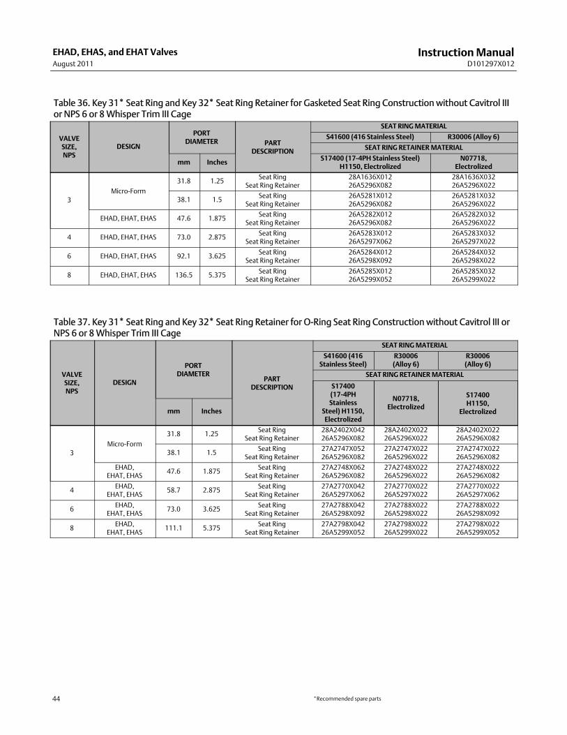
InstructionManualD101297X012
EHAD, EHAS, and EHAT ValvesAugust 2011
44
Table 36. Key 31* Seat Ring and Key 32* Seat Ring Retainer for Gasketed Seat Ring Construction without Cavitrol IIIor NPS 6 or 8Whisper Trim III Cage
VALVESIZE,NPS
DESIGN
PORTDIAMETER PART
DESCRIPTION
SEAT RINGMATERIAL
S41600 (416 Stainless Steel) R30006 (Alloy 6)
SEAT RING RETAINERMATERIAL
mm Inches S17400 (17-4PH Stainless Steel)H1150, Electrolized
N07718,Electrolized
3Micro-Form
31.8 1.25 Seat RingSeat Ring Retainer
28A1636X01226A5296X082
28A1636X03226A5296X022
38.1 1.5 Seat RingSeat Ring Retainer
26A5281X01226A5296X082
26A5281X03226A5296X022
EHAD, EHAT, EHAS 47.6 1.875 Seat RingSeat Ring Retainer
26A5282X01226A5296X082
26A5282X03226A5296X022
4 EHAD, EHAT, EHAS 73.0 2.875 Seat RingSeat Ring Retainer
26A5283X01226A5297X062
26A5283X03226A5297X022
6 EHAD, EHAT, EHAS 92.1 3.625 Seat RingSeat Ring Retainer
26A5284X01226A5298X092
26A5284X03226A5298X022
8 EHAD, EHAT, EHAS 136.5 5.375 Seat RingSeat Ring Retainer
26A5285X01226A5299X052
26A5285X03226A5299X022
Table 37. Key 31* Seat Ring and Key 32* Seat Ring Retainer for O-Ring Seat Ring Construction without Cavitrol III orNPS 6 or 8Whisper Trim III Cage
VALVESIZE,NPS
DESIGN
PORTDIAMETER
PARTDESCRIPTION
SEAT RINGMATERIAL
S41600 (416Stainless Steel)
R30006(Alloy 6)
R30006(Alloy 6)
SEAT RING RETAINERMATERIAL
S17400(17-4PHStainless
Steel) H1150,Electrolized
N07718,Electrolized
S17400H1150,
Electrolizedmm Inches
3Micro-Form
31.8 1.25 Seat RingSeat Ring Retainer
28A2402X04226A5296X082
28A2402X02226A5296X022
28A2402X02226A5296X082
38.1 1.5 Seat RingSeat Ring Retainer
27A2747X05226A5296X082
27A2747X02226A5296X022
27A2747X02226A5296X082
EHAD,EHAT, EHAS
47.6 1.875 Seat RingSeat Ring Retainer
27A2748X06226A5296X082
27A2748X02226A5296X022
27A2748X02226A5296X082
4 EHAD,EHAT, EHAS
58.7 2.875 Seat RingSeat Ring Retainer
27A2770X04226A5297X062
27A2770X02226A5297X022
27A2770X02226A5297X062
6 EHAD,EHAT, EHAS
73.0 3.625 Seat RingSeat Ring Retainer
27A2788X04226A5298X092
27A2788X02226A5298X022
27A2788X02226A5298X092
8 EHAD,EHAT, EHAS
111.1 5.375 Seat RingSeat Ring Retainer
27A2798X04226A5299X052
27A2798X02226A5299X022
27A2798X02226A5299X052
*Recommended spare parts

InstructionManualD101297X012
EHAD, EHAS, and EHAT ValvesAugust 2011
45
Table 38. Key 31* Seat Ring and Key 32* Seat Ring Retainer for an NPS 6 or 8 Valve withWhisper Trim III Cage andGasketed Seat Ring Construction
VALVESIZE,NPS
PORTDIAMETER PART
DESCRIPTION
SEAT RINGMATERIAL
S41600 (416 Stainless Steel) R30006 (Alloy 6)
SEAT RING RETAINERMATERIAL
mm Inches S17400 (17-4PH Stainless Steel)H1150, Electrolized
N07718,Electrolized
692.1 3.625 Seat Ring
Seat Ring Retainer26A5284X01226A5298X092
26A5284X03226A5298X022
73.0 2.875 Seat RingSeat Ring Retainer
20B3695X01227A4365X052
20B3695X03227A4365X042
8136.5 5.375 Seat Ring
Seat Ring Retainer26A5285X01226A5299X052
26A5285X03226A5299X022
111.1 4.375 Seat RingSeat Ring Retainer
20B3751X04227A4419X052
20B3751X02227A4419X032
Table 39. Key 31* Seat Ring and Key 32* Seat Ring Retainer for an NPS 6 or 8 Valve withWhisper Trim III Cage andO-Ring Seat Ring Construction
VALVESIZE,NPS
PORTDIAMETER PART
DESCRIPTION
SEAT RINGMATERIAL
S41600 (416Stainless Steel)
R30006(Alloy 6)
R30006(Alloy 6)
SEAT RING RETAINERMATERIAL
S17400 (17-4PHStainless Steel)
H1150N07718, Electrolized
S17400 H1150,For NACEMR0175-2002mm Inches
692.1 3.625 Seat Ring
Seat Ring Retainer27A2788X04226A5298X092
27A2788X02226A5298X022
27A2788X02226A5298X092
73.0 2.875 Seat RingSeat Ring Retainer
20B3696X01227A4365X052
20B3696X02227A4365X042
20B3696X02227A4365X052
8136.5 5.375 Seat Ring
Seat Ring Retainer27A2798X04226A5299X052
27A2798X02226A5299X022
27A2798X02226A5299X052
111.1 4.375 Seat RingSeat Ring Retainer
20B3752X04227A4419X052
20B3752X02227A4419X032
20B3752X02227A4419X052
*Recommended spare parts

InstructionManualD101297X012
EHAD, EHAS, and EHAT ValvesAugust 2011
46
Table 40. Key 31* Seat and Liner and Key 32* Seat Ring Retainer for Liner-Style Constructions
VALVESIZE,NPS
PORTDIAMETER
VALVEPART
DESCRIPTION
SEAT AND LINERMATERIAL
CB7CU-1 (17-4PHStainless Steel) H1075
R30006(Alloy 6)
SEAT RING RETAINERMATERIAL
mm Inches S17400 (17-4PHStainless Steel) H1150
N07718
3 47.6 1.875 EHAD, EHAT, EHAS Seat and LinerSeat Ring Retainer
38A6951X01226A5296X082
38A6951X02226A5296X022
4 73.0 2.875 EHAD, EHAT, EHAS Seat and LinerSeat Ring Retainer
38A6953X01226A5297X062
38A6953X02226A5297X022
6 92.1 3.625 EHAD, EHAT, EHAS Seat and LinerSeat Ring Retainer
38A6955X01226A5298X092
38A6955X02226A5298X022
8 136.5 5.375 EHAD, EHAT, EHAS Seat and LinerSeat Ring Retainer
38A6957X01226A5299X052
38A6957X02226A5299X022
Table 41. Key 31* Seat Ring for Valve with Cavitrol III Trim and O-Ring Seat Ring Construction
VALVE SIZE,NPS
2-STAGE 3-STAGE
S44004 (440CStainless Steel)
S44004 (440CStainless Steel)
3 20B6735X032 20B6734X032
4 20B6724X032 20B1222X042
6 20B1223X042 20B1221X032
8 20B6725X032 20B1220X032
Table 42. Key 32* Seat Ring Retainer for Valve with Cavitrol III Trim,Electrolized S17400 (17-4PH Stainless Steel) H1150VALVE SIZE,
NPS2-STAGE 3-STAGE
3468
27A2301X05227A4315X02227A4353X02227A4402X022
27A2308X03227A4327X04227A4365X05227A4419X052
*Recommended spare parts

InstructionManualD101297X012
EHAD, EHAS, and EHAT ValvesAugust 2011
47
Table 43. Key 33* Seat Ring O-Ring or Gasket
VALVESIZE,NPS
O-RING GASKET
For UseWith All O-RingSeat Ring Constructions
For All GasketedSeat Ring
ConstructionsEthylenePropylene
NitrileForMR0175-2002
FluorocarbonForMR0175-2002
S31600 (316 Stain-less Steel)/Graphite
3468
1D2269X00621H6247X00721H7774X003213A5599X052
1D2269X00421H6247069921H77740699213A5599X012
1D2269X00121H6247X00321H7774X002213A5599X022
19A2543X01219A4321X01218A2808X01218A2810X012
Table 44. Key 36* O-Ring for Cavitrol III Trim OnlyVALVE SIZE,
NPS2-STAGE 3-STAGE
3468
1H2921X00221K8776X00521P5548X00321F4492X0012
1C6280X00421H2917X00221F7294X00321D2673X0032
*Recommended spare parts

InstructionManualD101297X012
EHAD, EHAS, and EHAT ValvesAugust 2011
48
Emerson Process ManagementMarshalltown, Iowa 50158 USASorocaba, 18087 BrazilChatham, Kent ME4 4QZ UKDubai, United Arab EmiratesSingapore 128461 Singapore
www.Fisher.com
The contents of this publication are presented for informational purposes only, and while every effort has beenmade to ensure their accuracy, they are notto be construed as warranties or guarantees, express or implied, regarding the products or services described herein or their use or applicability. All sales aregoverned by our terms and conditions, which are available upon request. We reserve the right tomodify or improve the designs or specifications of suchproducts at any timewithout notice.
EFisher Controls International LLC 1986, 2011; All Rights Reserved
Fisher, Cavitrol, ENVIRO-SEAL, andWhisper Trim aremarks owned by one of the companies in the Emerson Process Management business division ofEmerson Electric Co. Emerson Process Management, Emerson, and the Emerson logo are trademarks and servicemarks of Emerson Electric Co. All othermarks are the property of their respective owners.
Neither Emerson, Emerson Process Management, nor any of their affiliated entities assumes responsibility for the selection, use or maintenanceof any product. Responsibility for proper selection, use, andmaintenance of any product remains solely with the purchaser and end user.


