www.Fisher.com
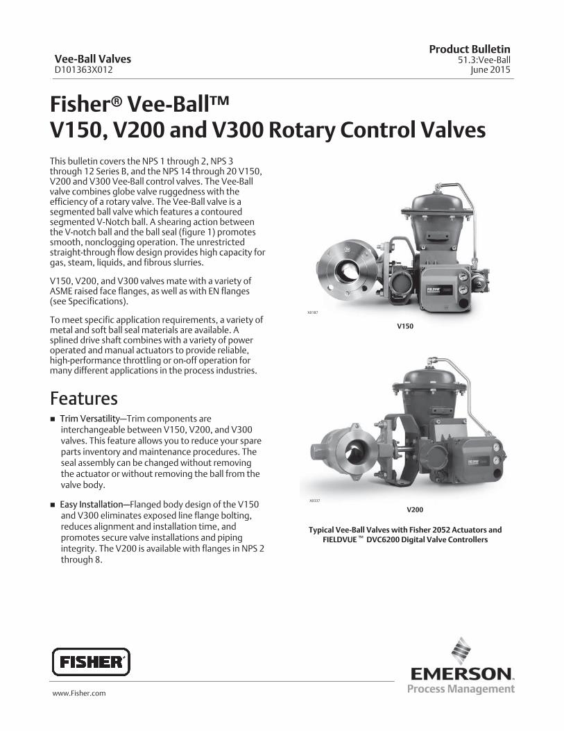
Fisher� Vee-Ball™ V150, V200 and V300 Rotary Control ValvesThis bulletin covers the NPS 1 through 2, NPS 3through 12 Series B, and the NPS 14 through 20 V150,V200 and V300 Vee-Ball control valves. The Vee-Ballvalve combines globe valve ruggedness with theefficiency of a rotary valve. The Vee-Ball valve is asegmented ball valve which features a contouredsegmented V-Notch ball. A shearing action betweenthe V-notch ball and the ball seal (figure 1) promotessmooth, nonclogging operation. The unrestrictedstraight-through flow design provides high capacity forgas, steam, liquids, and fibrous slurries.
V150, V200, and V300 valves mate with a variety ofASME raised face flanges, as well as with EN flanges(see Specifications).
To meet specific application requirements, a variety ofmetal and soft ball seal materials are available. Asplined drive shaft combines with a variety of poweroperated and manual actuators to provide reliable,high-performance throttling or on-off operation formany different applications in the process industries.
Features� Trim Versatility—Trim components are
interchangeable between V150, V200, and V300valves. This feature allows you to reduce your spareparts inventory and maintenance procedures. Theseal assembly can be changed without removingthe actuator or without removing the ball from thevalve body.
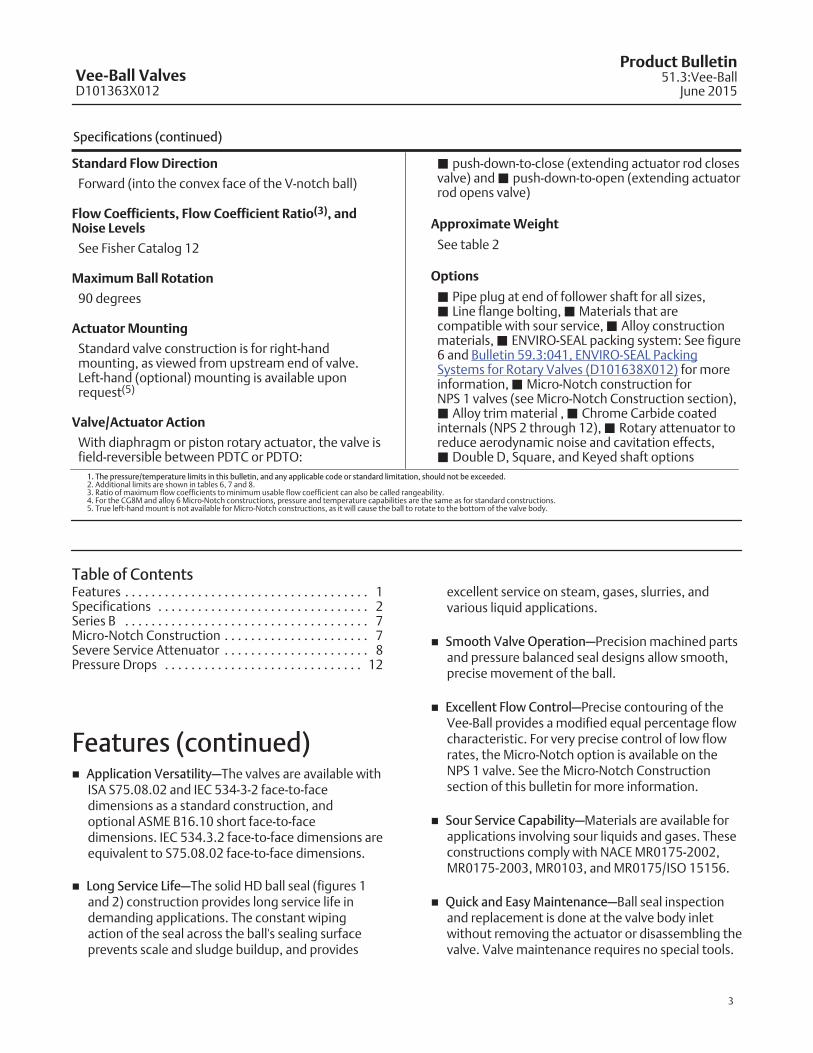
� Easy Installation—Flanged body design of the V150and V300 eliminates exposed line flange bolting,reduces alignment and installation time, andpromotes secure valve installations and pipingintegrity. The V200 is available with flanges in NPS 2through 8.
V150
X0187
X0337
V200
Typical Vee-Ball Valves with Fisher 2052 Actuators andFIELDVUE� DVC6200 Digital Valve Controllers
Vee-Ball ValvesD101363X012
Product Bulletin51.3:Vee-Ball
June 2015

Vee-Ball ValvesD101363X012
Product Bulletin51.3:Vee-BallJune 2015
2
Specifications
Valve Sizes
See table 1
Valve End Connection Styles
V150: Flanged valves that mate with CL150raised-face flanges and EN 1092-1 Type B raised-faceand Type F Recess
V200: Flangeless (all sizes) and flanged valves thatmate with CL600 raised-face flanges (NPS 2-8)
V300: Flanged valves that mate with CL300raised-face flanges and EN 1092-1 Type B raised-faceand Type F Recess
Maximum Inlet Pressures(1)
V150 or V300 WCC (or 1.0619 Steel), CF3M (or1.4409 SST), CG8M, LCC, M35-2, CK3McuN, CD3MN,and CD3MWCuN Valves: Consistent with CL150 forV150 or CL300 for V300 pressure-temperatureratings per ASME B16.34 or with PNpressure-temperature ratings shown in table 1. Note:CF3M is the standard material offering in Europe andAsia-Pacific. 1.0619 Steel and 1.4409 SST are alsostandard material offerings in Europe.
V200 WCC, CG8M, and LCC Valves: Consistent withapplicable pressure-temperature ratings in table 1 perASME B16.34.
CW2M: Consistent with applicablepressure-temperature ratings shown in table 6.Do not exceed the material temperature capabilitiesshown below or the pressure drop limitations.
Maximum Shutoff Pressure/Temperature Ratings(1)
Composition (Fisher TCM Plus or TCM Ultra), FlatMetal (NPS 3 through 12 valves only), HD and HighTemperature HD Metal Ball Seals and Flow Ring: Seetable 8.
Shutoff Classification(1)
Fisher TCM Plus or Ultra Ball Seal (Forward Flow):Class VI per ANSI/FCI 70-2 and per IEC 60534-4,Flat Metal Ball Seal for NPS 3 through 12 only(Forward Flow): Class IV per ANSI/FCI 70-2 and per IEC60534-4, HD (Heavy Duty) Ball Seal (Bidirectional Flow): 0.01%of valve capacity; Class IV per ANSI/FCI 70-2 and IEC60534-4; Maximum allowable pressure drop in
reverse flow is 6.9 bar (100 psi);High Temperature HD (Heavy Duty) Ball Seal(Bidirectional Flow): Class III per ANSI/FCI 70-2 and IEC60534-4Flow Ring Construction (Bidirectional Flow): 5% ofvalve capacity at full travelMicro-Notch Ball: Same leakage as standard ball
Construction Materials
See tables 4 and 5
Temperature Capabilities(1,2)
Composition SealsFisher TCM Plus: -46 to 232�C (-50 to 450�F) Fisher TCM Ultra: -46 to 260�C (-50 to 500�F) HD Metal Seals: -46 to 288�C (-50 to 550�F)High Temperature HD Metal Seal: 288 to 427�C (550to 800�F). Contact your Emerson ProcessManagement sales office if higher temperatures arerequired.Ceramic Micro-Notch Ball: -46 to 93�C (-50 to200�F)(4)
Flow Ring or Flat Metal Seal : -198 to 425�C (-325 to800�F)PEEK/PTFE Bearings: -198 to 260�C (-325 to 500�F)
Packing Constructions
PTFE V-ring: -46 to 232�C (-50 to 450�F)Graphite: -198 to 538�C (-325 to 1000�F)ENVIRO-SEAL� Single PTFE V-ring: -46 to 232�C (-50to 450�F) (for 100 ppm service requirements)ENVIRO-SEAL Graphite: -7 to 316�C (20 to 600�F) (for100 ppm service requirements). This packingarrangement can be used to 371�C (700�F) fornon-environmental service.
Flow Characteristic
Modified equal percentage
Dimensions
See figures 7, 8, and 10 for dimensions
Optional Face-to-Face Dimensions
� ASME B16.10 short face-to-face dimensions areavailable as an option for NPS 1 through 12 valves.Note that ASME B16.10 short dimensions are actuallylonger than ISA S75.08.02. See figure 11 fordimensions.
(continued)
Vee-Ball ValvesD101363X012
Product Bulletin51.3:Vee-Ball
June 2015
3
Specifications (continued)
Standard Flow Direction
Forward (into the convex face of the V-notch ball)
Flow Coefficients, Flow Coefficient Ratio(3), andNoise Levels
See Fisher Catalog 12
Maximum Ball Rotation
90 degrees
Actuator Mounting
Standard valve construction is for right-handmounting, as viewed from upstream end of valve.Left-hand (optional) mounting is available uponrequest(5)
Valve/Actuator Action
With diaphragm or piston rotary actuator, the valve isfield-reversible between PDTC or PDTO:
� push-down-to-close (extending actuator rod closesvalve) and � push-down-to-open (extending actuatorrod opens valve)
Approximate Weight
See table 2
Options
� Pipe plug at end of follower shaft for all sizes,� Line flange bolting, � Materials that arecompatible with sour service, � Alloy constructionmaterials, � ENVIRO-SEAL packing system: See figure6 and Bulletin 59.3:041, ENVIRO-SEAL PackingSystems for Rotary Valves (D101638X012) for moreinformation, � Micro-Notch construction for NPS 1 valves (see Micro-Notch Construction section),� Alloy trim material , � Chrome Carbide coatedinternals (NPS 2 through 12), � Rotary attenuator toreduce aerodynamic noise and cavitation effects,� Double D, Square, and Keyed shaft options
1. The pressure/temperature limits in this bulletin, and any applicable code or standard limitation, should not be exceeded.2. Additional limits are shown in tables 6, 7 and 8.3. Ratio of maximum flow coefficients to minimum usable flow coefficient can also be called rangeability.4. For the CG8M and alloy 6 Micro-Notch constructions, pressure and temperature capabilities are the same as for standard constructions.5. True left-hand mount is not available for Micro-Notch constructions, as it will cause the ball to rotate to the bottom of the valve body.
Table of ContentsFeatures 1. . . . . . . . . . . . . . . . . . . . . . . . . . . . . . . . . . . . .Specifications 2. . . . . . . . . . . . . . . . . . . . . . . . . . . . . . . .Series B 7. . . . . . . . . . . . . . . . . . . . . . . . . . . . . . . . . . . . .Micro-Notch Construction 7. . . . . . . . . . . . . . . . . . . . . .Severe Service Attenuator 8. . . . . . . . . . . . . . . . . . . . . .Pressure Drops 12. . . . . . . . . . . . . . . . . . . . . . . . . . . . . .
Features (continued)� Application Versatility—The valves are available with
ISA S75.08.02 and IEC 534-3-2 face-to-facedimensions as a standard construction, andoptional ASME B16.10 short face-to-facedimensions. IEC 534.3.2 face-to-face dimensions areequivalent to S75.08.02 face-to-face dimensions.
� Long Service Life—The solid HD ball seal (figures 1and 2) construction provides long service life indemanding applications. The constant wipingaction of the seal across the ball's sealing surfaceprevents scale and sludge buildup, and provides
excellent service on steam, gases, slurries, andvarious liquid applications.
� Smooth Valve Operation—Precision machined partsand pressure balanced seal designs allow smooth,precise movement of the ball.
� Excellent Flow Control—Precise contouring of theVee-Ball provides a modified equal percentage flowcharacteristic. For very precise control of low flowrates, the Micro-Notch option is available on theNPS 1 valve. See the Micro-Notch Constructionsection of this bulletin for more information.
� Sour Service Capability—Materials are available forapplications involving sour liquids and gases. Theseconstructions comply with NACE MR0175-2002,MR0175-2003, MR0103, and MR0175/ISO 15156.
� Quick and Easy Maintenance—Ball seal inspectionand replacement is done at the valve body inletwithout removing the actuator or disassembling thevalve. Valve maintenance requires no special tools.

Vee-Ball ValvesD101363X012
Product Bulletin51.3:Vee-BallJune 2015
4
� Structural Integrity—One-piece valve body improvesstructural integrity of the pressure boundary byeliminating leak paths that could be caused by thegaskets in two-piece, bolted valve designs.
� Exceptional Environmental Capabilities—Theoptional ENVIRO-SEAL packing systems aredesigned with very smooth shaft surfaces and liveloading to provide exceptional sealing. The seal ofthe ENVIRO-SEAL system can restrict emissions toless than the EPA (Environmental ProtectionAgency) limit of 100 ppm (parts per million).
Table 1. Valve Body Materials, End Connections, and Ratings
VALVE DESIGN VALVE BODY MATERIALSIZE RATINGS
NPS / DN ASME / PN
V150
WCC NPS 1, 1-1/2, 2, 3, 4, 6, 8, 10, 12, 14, 16, 20, 24x20(5) CL150
WCC / 1.0619(1)DN 80, 100, 150 PN 10-16
DN 200, 250, 300 PN 10 or PN 16
LCC
NPS 1, 1-1/2, 2, 3, 4, 6, 8, 10, 12 CL150
DN 80, 100, 150 PN 10-16
DN 200, 250, 300 PN 10 or PN 16
CF3M(2) NPS 1, 1-1/2, 2, 3, 4, 6, 8, 10, 12 CL150
CF3M/1.4409(1)DN 80, 100, 150 PN 10-16
DN 200, 250, 300 PN 10 or PN 16
CG8M NPS 1, 1-1/2, 2, 3, 4, 6, 8, 10, 12, 14, 16, 20, 24x20(5)
CL150
CW2M NPS 1, 1-1/2, 2, 3, 4, 6, 8, 10, 12
M35-2 NPS 1, 1-1/2, 2, 3, 4, 6, 8
CD3MN(3) NPS 1, 1-1/2, 2, 3, 4, 6, 8, 10, 12
CD3MWCuN(3) NPS 1, 1-1/2, 2, 3, 4, 6, 8, 10, 12
CK3MCuN NPS 1, 1-1/2, 2, 3, 4, 6, 8, 10, 12
V200(4)
WCC, LCC, CG8M, or CF3M(2)
NPS 1, 1-1/2, 2 CL150/300/600 flangeless
NPS 3, 4CL150 and CL300/600
flangeless
NPS 6, 8CL150/300 and CL600
flangeless
NPS 10 CL150 flangeless
WCC, LCC, or CG8M NPS 2, 3, 4, 6, 8 CL600
CW2M, M35-2, or CK3MCuN NPS 1, 1-1/2, 2, 3, 4, 6, 8 CL150/300/600 flangeless
CK3MCuN NPS 10 CL150 flangeless
V300
WCC NPS 1, 1-1/2, 2, 3, 4, 6, 8, 10, 12, 14, 16, 20 CL300
WCC / 1.0619(1)
DN 25, 40, 50 PN 10-40
DN 80, 100, 150 PN 25-40
DN 200, 250, 300 PN 25 or PN 40
LCC
NPS 1, 1-1/2, 2, 3, 4, 6, 8, 10, 12 CL300
DN 25, 40, 50 PN 10-40
DN 80, 100, 150 PN 25-40
DN 200, 250, 300 PN 25 or PN 40
CF3M(2) NPS 1, 1-1/2, 2, 3, 4, 6, 8, 10, 12 CL300
CF3M/1.4409(1)
DN 25, 40, 50 PN 10-40
DN 80, 100, 150 PN 25-40
DN 200, 250, 300 PN 25 or PN 40
CG8M NPS 1, 1-1/2, 2, 3, 4, 6, 8, 10, 12, 14, 16, 20
CL300
CW2M NPS 1, 1-1/2, 2, 3, 4, 6, 8
M35-2 NPS 1, 1-1/2, 2, 3, 4, 6, 8
CD3MN(3) NPS 1, 1-1/2, 2, 3, 4, 6, 8, 10, 12
CD3MWCuN(3) NPS 1, 1-1/2, 2, 3, 4, 6, 8, 10, 12
CK3MCuN NPS 1, 1-1/2, 2, 3, 4, 6, 8, 10, 12
1. WCC and EN Stl 1.0619 are dual certified. CF3M and EN SST 1.4409 are dual certified.2. CF3M is a standard offering in Europe and Asia Pacific.3. NORSOK compliant materials available upon request.4. Flangeless V200 assemblies mate with raised-face flanges.5. Valve body mates with NPS 24 ASME CL150 flanges. Internal based on NPS 20 valve design.

Vee-Ball ValvesD101363X012
Product Bulletin51.3:Vee-Ball
June 2015
5
Figure 1. Vee-Ball Construction Features, Seals (Fisher V150 Shown)
SEAL PROTECTOR RING
FLATMETALBALLSEAL
V-NOTCHBALL SHIMS
BODY
SPRINGSEAL
SEALPROTECTORRING
HD SEAL
RADIALSEAL
V-NOTCH BALL
WAVESPRING
BODY
SEAL PROTECTORRING
TCMBALL SEAL
V-NOTCHBALL
BODY
BACKUPRING
VIEW AHD BALL SEAL DETAIL
VIEW AFLAT METAL BALL SEAL DETAIL
FOR NPS 3 THROUGH 12
W6197-1
W5704-1
W4713-3
VIEW AFISHER TCM PLUS BALL SEALNPS 1, 1-1/2, AND 2 VALVES
VIEW A HIGH-TEMPERATURE HD BALL SEAL
SEALPROTECTORRING
WAVESPRING
RETAININGRINGS
PISTONRING
HDMETALSEAL
RETAINING RING(USE ONLY WHENATTENUATOR ISUSED)
SEALPROTECTOR RING
WAVESPRING
HDMETAL SEAL
PISTON RING
W8479
NPS 1, 1-1/2 & 2HD BALL SEAL
NPS 3 THROUGH 8 & NPS 14 THROUGH 20HD BALL SEAL
NPS 10 AND 12HD BALL SEAL

Vee-Ball ValvesD101363X012
Product Bulletin51.3:Vee-BallJune 2015
6
Figure 2. Vee-Ball Construction Features (Fisher V150 Shown)
W6099-1
BOTTOMFLANGE
HD BALL SEAL
PACKING FLANGEAND PACKING FOLLOWER
PIN
NPS 14, 16, AND 20 VALVES(HD BALL SEAL)
V-NOTCH BALL
FOLLOWERSHAFT
GROOVE PIN
BODY
SEE VIEW A(FIGURE 1)
SEALPROTECTORRING GASKET
TAPER KEY
BEARINGPACKING FOLLOWER
DRIVE SHAFT
NPS 3 THROUGH 12 VALVES(HD BALL SEAL SHOWN)
W7435

Vee-Ball ValvesD101363X012
Product Bulletin51.3:Vee-Ball
June 2015
7
Table 2. Valve Weights, Approximate
VALVE SIZE, NPSV150 V200 V300
kg lbs kg lbs kg lbs
1 5.6 13 4.5 10 8 17
1-1/2 8.2 19 6.4 14 12 27
2 9.1 21 10 23 17 38
3 13 43 15 34 28 61
4 26 57 22 48 37 81
6 42 93 36 80 60 133
8 72 158 62 136 103 226
10 107 235 114 252 200 440
12 157 347 - - - - - - 293 645
14 247 545 - - - - - - 374 825
16 333 735 - - - - - - 510 1125
20 524 1155 - - - - - - 755 1661
24 757 1666 - - - - - - - - - - - -
Series BNPS 3 through 12 have been changed to reduce partsand to improve control performance. The V-notch Ballnow resembles the NPS 14 through 20 V-notch Ball.The pressed-in bushings have been eliminated, as wellas the thrust washer.
Micro-Notch ConstructionFor very precise control of low flow rates, theMicro-Notch construction (see figure 3) is available onNPS 1 valves. Three Micro-Notch ball materials areavailable: chrome-plated CG8M (317 stainless steel),solid alloy 6, and solid VTC ceramic. A VTC ceramic HDseal is standard with the VTC ceramic ball. For theCG8M and alloy 6 constructions, pressure andtemperature capabilities are the same as for standardconstructions. For the ceramic construction,maximum temperature is 93�C (200�F).
Figure 3. Typical Micro-Notch Ball and Shaft
MICRO-
NOTCH
VEE BALL
DRIVE SHAFTW6256
For further information, please refer to the FisherVee-Ball V150, V200 and V300 Rotary Control ValvesNPS 1 through 12 instruction manual (D101554X012).
In addition to the standard Micro-Notch offering,options are available in both low (Micro-Scratch) andhigh (Macro-Notch) flow construction. Contact yourEmerson Process Management sales office for moreinformation.

Vee-Ball ValvesD101363X012
Product Bulletin51.3:Vee-BallJune 2015
8
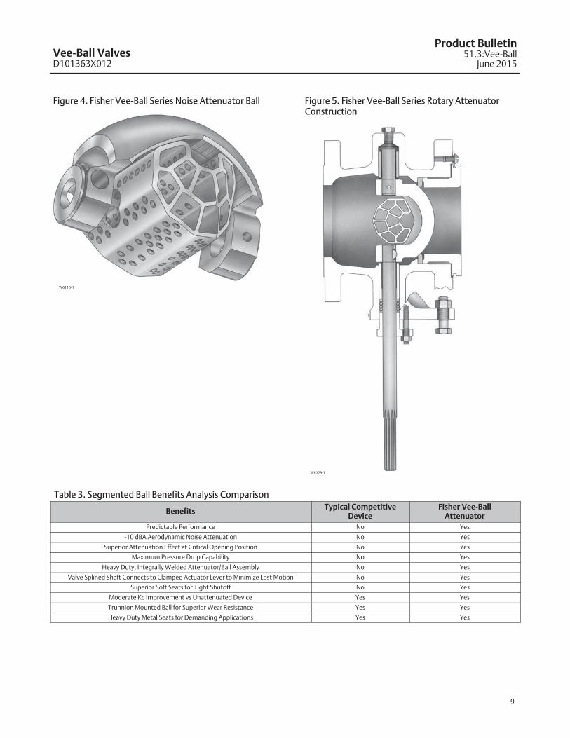
Severe Service AttenuatorFisher Vee-Ball series valves (V150, V200, and V300),with the severe service attenuator, combine theefficiency of a rotary valve with the energy absorbingcapability of a special trim to provide improvedperformance for demanding applications. The Fisherattenuator design can be utilized in both liquid and gasservice to reduce cavitation and noise effects thatcause pipeline vibration. See table 3 for a competitivecomparison.
The attenuator will not change the NACE complianceof the Vee-Ball valve. When a rotary noise attenuator isinstalled in a Vee-Ball valve, the V-Notch is no longer apoint of high-velocity erosion. As a result, the CoCr-AV-Notch option is not required when a rotaryattenuator is used. The rotary attenuator and CoCr-AV-Notch options are not available together.
Features
� Trim Versatility — Trim components areinterchangeable for Fisher V150, V200, and V300valves. This feature allows you to reduce your spareparts inventory and maintenance procedures.
� Attenuator-Ball Fabrication — The ball-attenuatorconstruction provides structural integrity becauseof its rugged fabrication weld.
� Attenuator Performance — Up to -10 dBA acousticalattenuation, and a Kc = 1.0 for hydrodynamics areachievable depending on service conditions.
Attenuator Ball Material
Standard attenuator ball material is CG8M, M35-1,CW2M, or CK3McuN.
Standard Flow Direction
Forward flow direction is into the convex face of theV-notch ball. The valve with the attenuator must beplaced in the forward flow direction for the attenuatorto be effective.
Actuator Mounting
Right-hand or left-hand as viewed from the upstreamend of the valve. Counter-clockwise to close for bothmounting styles.
Vee-Ball ValvesD101363X012
Product Bulletin51.3:Vee-Ball
June 2015
9
Figure 4. Fisher Vee-Ball Series Noise Attenuator Ball
W6116-1
Figure 5. Fisher Vee-Ball Series Rotary AttenuatorConstruction
W6129-1
Table 3. Segmented Ball Benefits Analysis Comparison
BenefitsTypical Competitive
DeviceFisher Vee-Ball
Attenuator
Predictable Performance No Yes
-10 dBA Aerodynamic Noise Attenuation No Yes
Superior Attenuation Effect at Critical Opening Position No Yes
Maximum Pressure Drop Capability No Yes
Heavy Duty, Integrally Welded Attenuator/Ball Assembly No Yes
Valve Splined Shaft Connects to Clamped Actuator Lever to Minimize Lost Motion No Yes
Superior Soft Seats for Tight Shutoff No Yes
Moderate Kc Improvement vs Unattenuated Device Yes Yes
Trunnion Mounted Ball for Superior Wear Resistance Yes Yes
Heavy Duty Metal Seats for Demanding Applications Yes Yes
Vee-Ball ValvesD101363X012
Product Bulletin51.3:Vee-BallJune 2015
10
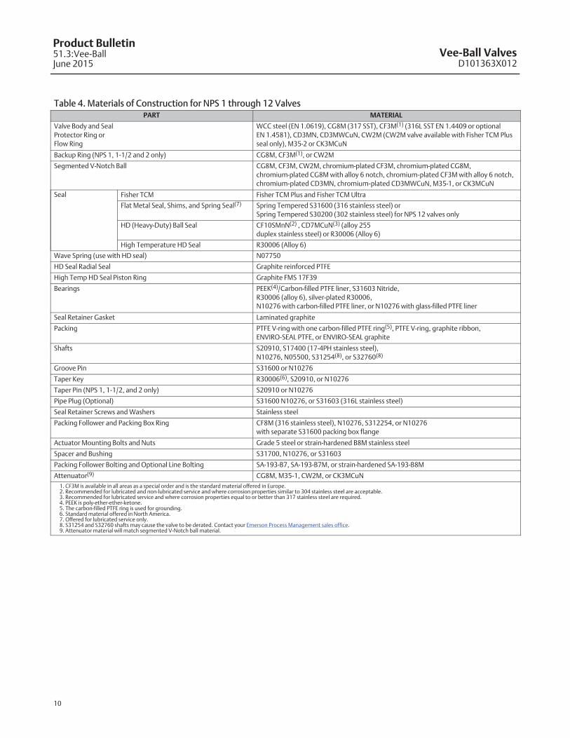
Table 4. Materials of Construction for NPS 1 through 12 ValvesPART MATERIAL
Valve Body and Seal
Protector Ring or
Flow Ring
WCC steel (EN 1.0619), CG8M (317 SST), CF3M(1) (316L SST EN 1.4409 or optional
EN 1.4581), CD3MN, CD3MWCuN, CW2M (CW2M valve available with Fisher TCM Plus
seal only), M35-2 or CK3MCuN
Backup Ring (NPS 1, 1-1/2 and 2 only) CG8M, CF3M(1), or CW2M
Segmented V-Notch Ball CG8M, CF3M, CW2M, chromium-plated CF3M, chromium-plated CG8M,
chromium-plated CG8M with alloy 6 notch, chromium-plated CF3M with alloy 6 notch,
chromium-plated CD3MN, chromium-plated CD3MWCuN, M35-1, or CK3MCuN
Seal Fisher TCM Fisher TCM Plus and Fisher TCM Ultra
Flat Metal Seal, Shims, and Spring Seal(7) Spring Tempered S31600 (316 stainless steel) or
Spring Tempered S30200 (302 stainless steel) for NPS 12 valves only
HD (Heavy-Duty) Ball Seal CF10SMnN(2) , CD7MCuN(3) (alloy 255
duplex stainless steel) or R30006 (Alloy 6)
High Temperature HD Seal R30006 (Alloy 6)
Wave Spring (use with HD seal) N07750
HD Seal Radial Seal Graphite reinforced PTFE
High Temp HD Seal Piston Ring Graphite FMS 17F39
Bearings PEEK(4)/Carbon-filled PTFE liner, S31603 Nitride,
R30006 (alloy 6), silver-plated R30006,
N10276 with carbon-filled PTFE liner, or N10276 with glass-filled PTFE liner
Seal Retainer Gasket Laminated graphite
Packing PTFE V-ring with one carbon-filled PTFE ring(5), PTFE V-ring, graphite ribbon,
ENVIRO-SEAL PTFE, or ENVIRO-SEAL graphite
Shafts S20910, S17400 (17-4PH stainless steel),
N10276, N05500, S31254(8), or S32760(8)
Groove Pin S31600 or N10276
Taper Key R30006(6), S20910, or N10276
Taper Pin (NPS 1, 1-1/2, and 2 only) S20910 or N10276
Pipe Plug (Optional) S31600 N10276, or S31603 (316L stainless steel)
Seal Retainer Screws and Washers Stainless steel
Packing Follower and Packing Box Ring CF8M (316 stainless steel), N10276, S312254, or N10276
with separate S31600 packing box flange
Actuator Mounting Bolts and Nuts Grade 5 steel or strain-hardened B8M stainless steel
Spacer and Bushing S31700, N10276, or S31603
Packing Follower Bolting and Optional Line Bolting SA-193-B7, SA-193-B7M, or strain-hardened SA-193-B8M
Attenuator(9) CG8M, M35-1, CW2M, or CK3MCuN
1. CF3M is available in all areas as a special order and is the standard material offered in Europe.2. Recommended for lubricated and non-lubricated service and where corrosion properties similar to 304 stainless steel are acceptable.3. Recommended for lubricated service and where corrosion properties equal to or better than 317 stainless steel are required.4. PEEK is poly-ether-ether-ketone.5. The carbon-filled PTFE ring is used for grounding.6. Standard material offered in North America.7. Offered for lubricated service only.8. S31254 and S32760 shafts may cause the valve to be derated. Contact your Emerson Process Management sales office.9. Attenuator material will match segmented V-Notch ball material.

Vee-Ball ValvesD101363X012
Product Bulletin51.3:Vee-Ball
June 2015
11
Table 5. Materials of Construction for NPS 14, 16 and 20 ValvesPart Material
Valve Body, Seal Protector Ring, and Flow Ring WCC steel or CG8M (317 stainless steel)
Segmented V-Notch Ball Chromium-plated CG8M, CG8M, Chromium-plated CG8M with alloy 6 notch
Ball SealFisher TCM Fisher TCM Plus and Fisher TCM Ultra
HD (Heavy-Duty Metal) CF10SMnN(1) , CD7MCuM(2) (alloy 225 duplex stainless steel) or R30006 (alloy 6)
Wave Spring (use with HD seal) N07750
Radial Seal (use with HD seal) PTFE with N10276 spring
BearingsPEEK/PTFE(3), S44004 (440C stainless steel--use with S17400 [17-4PH stainless steel]
shafts, alloy 6B, and silver plated alloy 6B
Thrust Washer (use with metal bearings) Alloy 6B
Seal Retainer Gasket Laminated Graphite
PackingPTFE V-ring with one conductive V-ring(4), PTFE V-ring, graphite ribbon, ENVIRO-SEAL
PTFE, or ENVIRO-SEAL graphite
Shafts S17400 (17-4 stainless steel) or S20910
Pins S20910
Pipe Plug S31700 (317 stainless steel)
Packing Follower Bolting B7M steel or strain-hardened B8M stainless steel
Retainer Screw B8M stainless steel
Packing Follower and Packing Box ring S31600 (316 stainless steel)
Packing Flange Steel or S31600
Actuator Mounting Bolts and Nuts Grade 5 steel or strain-hardened B8M stainless steel
Gasket (used with bottom flange) S31603 (316L stainless steel) spiral wound
Stud and Hex Nut (used with bottom flange) B7 steel or strain-hardened B8M stainless steel
Attenuator CG8M
1. Recommended where corrosion properties similar to 304 stainless steel are acceptable.2. Recommended for lubricated service and where corrosion properties equal to or better than S31700 stainless steel.3. PEEK (Poly-ether-ether-ketone) w/PTFE liner.4. A carbon-filled PTFE ring is used for grounding.
Figure 6. Typical ENVIRO-SEAL Packing Arrangements
PACKINGBOX STUD
VALVESHAFT
PACKINGFLANGE
PACKINGFOLLOWER
SPRINGS
VALVEBODY
ANTI-EXTRUSIONRINGS
PACKINGBOX RING
PTFEPACKINGV-RINGSSHOWN
VALVESHAFT
PACKINGFLANGE PACKING
BOXRING
GRAPHITEPACKINGSETPACKING
FOLLOWER
SPRINGS
PTFE PACKING GRAPHITE PACKING
W6125-1
W5806-2

Vee-Ball ValvesD101363X012
Product Bulletin51.3:Vee-BallJune 2015
12
Table 6. Maximum Allowable Inlet Pressure for CW2M Valves
TEMPERATURECW2M(1)
150(2) 300(2) PN 10(2) PN 16(2) PN 25(2) PN 40(2)
�C Bar
–46 to 3850
100150200232
20.019.517.715.813.812.7
51.751.751.550.348.347.0
10.09.99.49.49.19.1
16.015.915.115.114.614.6
25.024.823.623.622.922.9
40.039.637.837.836.636.6
�F Psig
–50 to 100200300400450
290260230200185
750750730700680
145144137133133
232230219212212
362359342331331
580575548530530
1. This material is not listed in EN 12516‐1 or ASME B16.34. Also see the Installation section.2. The designations PN or 150 and 300 are used only to indicate relative pressure‐retaining capabilities and are not EN or ASME pressure‐temperature rating class designations.
Pressure DropsPressure drop limits of any given valve are based onvalve body, and trim material limits. To find theappropriate pressure drop limitation, choose thedesired valve size and temperature range. Then searchtable 7 for body limitations and table 8 for trim
limitations. Information on limits for S31254, CW2M,M35-2, CD3MN, CD3MWCuN, and other alloyconstructions can be obtained by contacting yourEmerson Process Management sales office. The lowestnumber from the tables is the appropriate limit. Thetables for both trim and body limits must beconsulted.
Table 7. Maximum Allowable Shutoff Pressure Drops (Body Ratings) based on Carbon Steel and Stainless Steel ValveBody Types. (The tables for both trim and body limits must be consulted.)
TEMPERATURERANGE
PRESSURE CLASS
WCCCL150
316L SSTCL150
317 SSTCL150
LCCCL150
WCCCL300
316L SSTCL300
317 SSTCL300
LCCCL300
WCCCL600
316L SSTCL600
317 SSTCL600
LCCCL600
�C Bar
-46 to -29 - - - 15.9 19.0 20 - - - 41.4 49.6 51.7 - - - 82.7 99.3 103
-29 to 38 20.0 15.9 19.0 20 51.7 41.4 49.6 51.7 103 82.7 99.3 103
93 17.9 13.4 16.2 17.9 51.7 34.8 42.7 51.7 103 70.0 85.5 103
149 15.9 12.1 14.8 15.9 50.3 31.4 38.6 50.3 100 62.7 77.2 100
204 13.8 11.0 13.4 13.8 48.6 28.6 35.5 48.6 97.2 56.9 70.6 97.2
232 12.8 10.7 12.8 12.8 47.2 27.9 34.5 47.2 94.5 54.8 68.6 94.5
260 11.7 10.0 11.7 11.7 45.9 26.2 33.1 45.9 91.7 52.7 65.8 91.7
316 10.7 9.9 10.7 10.7 43.8 25.5 32.1 43.8 87.6 51.0 64.1 87.6
343 9.65 9.7 8.62 9.65 41.7 23.8 31.0 41.7 83.4 49.6 62.4 83.4
371 8.62 8.6 7.58 - - - 40.7 23.8 30.7 - - - 81.0 48.3 60.0 - - -
399 6.55 6.6 6.55 - - - 34.8 23.1 29.3 - - - 69.6 46.2 58.9 - - -
427 5.52 5.5 5.52 - - - 28.3 22.8 29.0 - - - 56.9 45.5 58.3 - - -
�F Psi
-50 to -20 - - - 230 275 290 - - - 600 720 750 - - - 1200 1440 1500
-20 to 100 290 230 275 290 750 600 720 750 1500 1200 1440 1500
200 260 195 235 260 750 505 620 750 1500 1015 1240 1500
300 230 175 215 230 730 455 560 730 1455 910 1120 1455
400 200 160 195 200 705 415 515 705 1410 825 1025 1410
450 185 155 185 185 685 405 500 685 1370 795 995 1370
500 170 145 170 170 665 380 480 665 1330 765 955 1330
550 155 143 155 155 635 370 465 635 1270 740 930 1270
600 140 140 140 140 605 360 450 605 1210 720 905 1210
650 125 125 125 125 590 350 445 590 1175 700 890 1175
700 110 110 110 - - - 570 345 430 - - - 1135 685 870 - - -
750 95 95 95 - - - 505 335 425 - - - 1010 670 855 - - -
800 80 80 80 - - - 410 330 420 - - - 825 660 845 - - -

Vee-Ball ValvesD101363X012
Product Bulletin51.3:Vee-Ball
June 2015
13
Table 8. Maximum Allowable Shutoff Pressure Drops based on Trim (Bearing and Seal). (Note: Do not exceed the PN or ASME pressure/temperature rating of the valve or mating flanges.)
BEARINGMATERIAL
BALL SEALTEMPERATURE
RANGE, �C
VALVE SIZE, NPS
1 1-1/2 2 3 4 6 8 10 12 14 16 20
Bar
PEEK/PTFE
Fisher TCM Plus or
Ultra
-46 to 38 51.7 51.7 51.7 51.7 51.7 51.7 51.7 40.2 37.6 31.0 23.8 31.0
93 37.9 37.9 37.9 37.9 37.9 37.9 37.9 37.9 37.6 31.0 23.8 31.0
149 24.1 24.1 24.1 24.1 24.1 24.1 24.1 24.1 24.1 24.1 23.8 24.1
204 10.3 10.3 10.3 10.3 10.3 10.3 10.3 10.3 10.3 10.3 10.3 10.3
232 3.45 3.45 3.45 3.45 3.45 3.45 3.45 3.45 3.45 3.45 3.45 3.45
HD Seal(1) -46 to 260 51.7 51.7 51.7 51.7 51.7 51.7 51.7 40.9 38.1 31.0 26.5 31.0
Flat Metal(2) -73 to 260 - - - - - - - - - 20.7 20.7 20.7 20.7 10.3 10.3 - - - - - - - - -
Flow Ring 260 103.4 103.4 103.4 103.4 72.4 75.2 73.8 40.5 37.7 40.5 35.0 44.7
R30006
HD Seal(1) -46 to 288 51.7 50.0 25.7 17.5 11.0 10.9 11.2 6.14 5.72 6.14 7.52 6.83
High Temp HD
Seal(1) 228 to 427 38.3(3) 37.5(3) 19.3(3) 13.2(3) 8.3(3) 8.2(3) 8.4(3) 4.6(3) 4.3(3) - - - - - - - - -
Flat Metal(2) -73 to 427 - - - - - - - - - 17.0 10.1 10.7 10.6 5.86 5.52 - - - - - - - - -
Flow Ring 427 74.5 49.6 26.8 18.8 10.9 11.2 11.1 6.07 5.65 6.07 7.31 6.69
R30006 Silver
Plated
HD Seal(1) -46 to 288 51.7 51.7 51.7 35.0 22.1 21.8 22.5 12.3 11.4 12.3 13.2 13.7
High Temp HD
Seal(1) 228 to 427 38.3(3) 38.3(3) 38.3(3) 26.3(3) 16.5(3) 16.3(3) 16.9(3) 9.2(3) 8.6(3) - - - - - - - - -
Flat Metal(2) -73 to 427 - - - - - - - - - 20.7 20.1 20.7 20.7 10.3 10.3 - - - - - - - - -
Flow Ring 427 103.4 103.4 53.5 37.6 21.8 22.5 22.2 12.1 11.3 12.1 14.6 13.4
S31603L Nitride
HD Seal(1) -46 to 288 51.0 51.0 51.0 51.7 36.7 36.3 37.4 20.5 19.1 - - - - - - - - -
High Temp HD
Seal(1) 228 to 427 - - - - - - - - - 38.3(3) 27.6(3) 27.2(3) 28.1(3) 15.4(3) 14.3(3) - - - - - - - - -
Flat Metal(2) -73 to 427 - - - - - - - - - 20.7 20.7 20.7 20.7 10.3 10.3 - - - - - - - - -
Flow Ring 427 99.3 99.3 88.9 62.7 36.3 37.4 37.0 20.2 18.8 - - - - - - - - -
BEARINGMATERIAL
BALL SEALTEMPERATURE
RANGE, �FPsi
PEEK/PTFE
Fisher TCM Plus or
Ultra
-50 to 100 750 750 750 750 750 750 750 583 545 450 345 450
200 550 550 550 550 550 550 550 550 545 450 345 450
300 350 350 350 350 350 350 350 350 350 350 345 350
400 150 150 150 150 150 150 150 150 150 150 150 150
450 50 50 50 50 50 50 50 50 50 50 50 50
HD Seal(1) -50 to 500 750 750 750 750 750 750 750 593 553 450 384 450
Flat Metal(2) -100 to 500 - - - - - - - - - 300 300 300 300 150 150 - - - - - - - - -
Flow Ring 500 1500 1500 1500 1500 1050 1090 1070 587 547 587 508 648
R30006
HD Seal(1) -50 to 550 750 725 373 254 160 158 163 89 83 89 109 99
High Temp HD
Seal(1) 550 to 800 555(3) 544(3) 280(3) 191(3) 120(3) 119(3) 122(3) 67(3) 62(3) - - - - - - - - -
Flat Metal(2) -100 to 800 - - - - - - - - - 246 146 155 154 85 80 - - - - - - - - -
Flow Ring 800 1080 720 388 273 158 163 161 88 82 88 106 97
R30006 Silver
Plated
HD Seal(1) -50 to 550 750 750 750 508 320 316 326 178 166 178 192 198
High Temp HD
Seal(1) 550 to 800 555(3) 555(3) 555(3) 381(3) 240(3) 237(3) 245(3) 134(3) 125(3) - - - - - - - - -
Flat Metal(2) -100 to 800 - - - - - - - - - 300 292 300 300 150 150 - - - - - - - - -
Flow Ring 800 1500 1500 776 546 316 326 322 176 164 176 212 194
S31603L Nitride
HD Seal(1) -50 to 550 740 740 740 750 533 527 543 297 277 - - - - - - - - -
High Temp HD
Seal(1) 550 to 800 - - - - - - - - - 555(3) 400(3) 395(3) 407(3) 223(3) 208(3) - - - - - - - - -
Flat Metal(2) -100 to 800 - - - - - - - - - 300 300 300 300 150 150 - - - - - - - - -
Flow Ring 800 1440 1440 1290 910 527 543 537 293 273 - - - - - - - - -1. Pressure drops shown for HD seals are for forward flow only. For reverse flow with HD seal, limit pressure drop to 6.9 bar (100 psig).2. Lubricated service only.3. Consult your Emerson Process Management sales office if higher pressure drops are required.
Vee-Ball ValvesD101363X012
Product Bulletin51.3:Vee-BallJune 2015
14
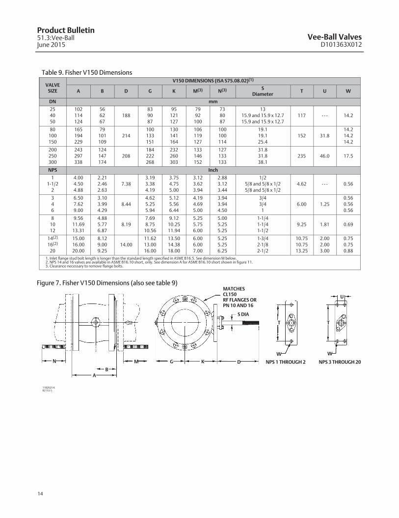
Table 9. Fisher V150 Dimensions
VALVESIZE
V150 DIMENSIONS (ISA S75.08.02)(1)
A B D G K M(3) N(3) SDiameter
T U W
DN mm
25
40
50
102
114
124
56
62
67188
83
90
87
95
121
127
79
92
100
73
80
87
13
15.9 and 15.9 x 12.7
15.9 and 15.9 x 12.7117 - - - 14.2
80
100
150
165
194
229
79
101
109214
100
133
151
130
141
164
106
119
127
100
100
114
19.1
19.1
25.4152 31.8
14.2
14.2
14.2
200
250
300
243
297
338
124
147
174208
184
222
268
232
260
303
133
146
152
127
133
133
31.8
31.8
38.1235 46.0 17.5
NPS Inch
1
1-1/2
2
4.00
4.50
4.88
2.21
2.46
2.637.38
3.19
3.38
4.19
3.75
4.75
5.00
3.12
3.62
3.94
2.88
3.12
3.44
1/2
5/8 and 5/8 x 1/2
5/8 and 5/8 x 1/24.62 - - - 0.56
3
4
6
6.50
7.62
9.00
3.10
3.99
4.298.44
4.62
5.25
5.94
5.12
5.56
6.44
4.19
4.69
5.00
3.94
3.94
4.50
3/4
3/4
16.00 1.25
0.56
0.56
0.56
8
10
12
9.56
11.69
13.31
4.88
5.77
6.878.19
7.69
8.75
10.56
9.12
10.25
11.94
5.25
5.75
6.00
5.00
5.25
5.25
1-1/4
1-1/4
1-1/29.25 1.81 0.69
14(2)
16(2)
20
15.00
16.00
20.00
8.12
9.00
9.2514.00
11.62
13.00
16.00
13.50
14.38
18.00
6.00
6.00
7.00
5.25
5.25
6.25
1-3/4
2-1/8
2-1/2
10.75
10.75
13.25
2.00
2.00
3.00
0.75
0.75
0.88
1. Inlet flange stud bolt length is longer than the standard length specified in ASME B16.5. See dimension M below.2. NPS 14 and 16 valves are available in ASME B16.10 short, only. See dimension A for ASME B16.10 short shown in figure 11.3. Clearance necessary to remove flange bolts.
Figure 7. Fisher V150 Dimensions (also see table 9)
11B2625-KB2153-5
N
BA
M G K D
S DIA
MATCHESCL150RF FLANGES ORPN 10 AND 16
T
W W
T
U
NPS 1 THROUGH 2 NPS 3 THROUGH 20

Vee-Ball ValvesD101363X012
Product Bulletin51.3:Vee-Ball
June 2015
15
Table 10. Fisher V200 Flangeless Dimensions
VALVESIZE, NPS
V200 DIMENSIONS (ISA S75.08.02)ASME B16.5RF FLANGESA B D G K
MR R1 S T U W
CL150 CL300 CL600
mm
1 102 56
188
81 95 176 202 202 51 102 12.7
117 - - - 14.2
CL150, 300,
and 600
1-1/2 114 62 89 121 189 224 224 73 119 15.7 and 15.7 x 12.7
2 124 67 106 127 211 236 236 92 137 15.7 and 15.7 x 12.7
3
4
6
165
194
229
79
101
109
214
117
133
159
130
141
164(1)
254
286
343
279
305
362
286
343
413
127
157
216
167
197
260
19.1
19.1
25.4
152 32 14.2
8 243 124208
195 232 343 387 426 270 31431.8 235 46 17.5
10 297 147 222 260 419 - - - - - - 324 368 CL150
Inch
1 4.00 2.21
7.38
3.19 3.75 6.94 7.94 7.94 2 4.00 1/2
4.62 - - - 0.56
CL150, 300,
and 600
1-1/2 4.50 2.46 3.50 4.75 7.44 8.81 8.81 2.88 4.68 5/8 and 5/8 x 1/2
2 4.88 2.63 4.19 5.00 8.31 9.31 9.31 3.63 5.38 5/8 and 5/8 x 1/2
3
4
6
6.50
7.62
9.00
3.10
3.99
4.29
8.44
4.62
5.25
6.25
5.12
5.56
6.44(1)
10.00
11.25
13.50
11.00
12.00
14.25
11.25
13.50
16.25
5.00
6.19
8.50
6.56
7.76
10.24
3/4
3/4
1
6.00 1.25 0.56
8 9.56 4.888.19
7.69 9.12 13.50 15.25 16.75 10.63 12.381-1/4 9.25 1.81 0.69
10 11.69 5.77 8.75 10.25 16.50 - - - - - - 12.75 14.50 CL150
1. 179 mm (7.06 inches) for NPS 6, CL600 valves only.
Figure 8. Fisher V200 Dimensions (also see table 10)
12B3060-LB2331-2
A
B
M
G K D
S∅
R∅
R1
T
W
NPS 1 THROUGH 2
W
T
U
NPS 3 THROUGH 20
11B2625-K

Vee-Ball ValvesD101363X012
Product Bulletin51.3:Vee-BallJune 2015
16
Table 11. Fisher V200 Flanged CL600 Dimensions
VALVE SIZE
DIMENSIONS (ANSI/ISA 75.08.02)APPROXIMATE
WEIGHTA B D G K M (Qty) Bolt SizeFlange HoleThread, Inch
SDiameter
T U W
DN mm kg
50 124 67 188 106 127 121 (16) 5/8-11 UNC 5/8-11 UNC 16 117 - - -14.2
17
80 165 79 214 117 130 140 (16) 3/4-10 UNC 3/4-10 UNC 19 152 32 28
100 194 101 214 133 141 165 (16) 7/8-9 UNC - - - 19 152 32 14.2 48
150 229 109 214 159 164 197 (24) 1-8 UNC 1-8 UNC 25 152 32 14.2 93
200 243 124 208 195 232 216 (24) 1-1/8-8 UNC 1-1/8-8 UNC 32 235 46 17.5 160
NPS Inch lbs
2 4.88 2.63 7.38 4.19 5.00 4.75 (16) 5/8-11 UNC 5/8-11 UNC 5/8 4.62 - - -0.56
38
3 6.50 3.10 8.44 4.62 5.12 5.50 (16) 3/4-10 UNC 3/4-10 UNC 3/4 6.00 1.25 61
4 7.62 3.99 8.44 5.25 5.56 6.50 (16) 7/8-9 UNC - - - 3/4 6.00 1.25 0.56 105
6 9.00 4.29 8.44 6.25 6.44 7.75 (24) 1-8 UNC 1-8 UNC 1 6.00 1.25 0.56 205
8 9.56 4.88 8.19 7.69 9.12 8.50 (24) 1-1/8-8 UNC 1-1/8-8 UNC 1-1/4 9.25 1.81 0.69 353
Figure 9. Fisher V200 CL600 Flanged Dimensions (also see table 11)
MATCHES CL600 RF FLANGES
MG K D
S∅
W∅ W∅
T
U
T
A
BM
B2330-3
NPS 2 NPS3 THROUGH 8

Vee-Ball ValvesD101363X012
Product Bulletin51.3:Vee-Ball
June 2015
17
Table 12. Fisher V300 Dimensions
VALVESIZE,
V300 DIMENSIONS (ISA S75.08.02)
A B D G K M(2) N(2) SDiameter
T U W
DN(1) mm
25
40
50
102
114
124
56
62
67188
81
89
106
95
121
127
100
114
106
94
108
100
13
16 and 16 X 13
16 and 16 X 13117 - - -
14.280
100
150
165
194
229
79
101
109214
117
133
159
130
141
164
133
140
152
121
127
140
19
19
25152 32
200
250
300
243
297
338
124
147
174208
195
222
268
232
260
303
165
186
198
152
173
186
32
32
38235 46 17.5
356 mm
(14-in.)381 206 356 295 343 197 178 44.5 273 50.8 19.5
406 mm
(16-in.)406 228 356 338 356 210 191 53.8 273 50.8 19.5
NPS Inch
1
1-1/2
2
4.00
4.50
4.88
2.21
2.46
2.637.38
3.19
3.50
4.19
3.75
4.75
5.00
3.94
4.50
4.19
3.69
4.25
3.94
1/2
5/8 and 5/8 X 1/2
5/8 and 5/8 X 1/24.62 - - -
0.563
4
6
6.50
7.62
9.00
3.10
3.99
4.298.44
4.62
5.25
6.25
5.12
5.56
6.44
5.25
5.50
6.00
4.75
5.00
5.50
3/4
3/4
16.00 1.25
8
10
12
9.56
11.69
13.31
4.88
5.77
6.878.19
7.69
8.75
10.56
9.12
10.25
11.94
6.50
7.31
7.81
6.00
6.81
7.31
1-1/4
1-1/4
1-1/29.25 1.81 0.69
14
16
15.00
16.00
8.12
9.00
14.00
14.00
11.62
13.31
13.50
14.38
7.75
8.25
7.00
7.50
1-3/4
2-1/810.75 2.00 0.75
1. DN25, 40, 50, 80, and 100 are the only sizes offered in V300 for Europe.2. Clearance necessary to remove flange bolts.
Figure 10. Fisher V300 Dimensions (also see table 12)
MATCHES CL300 RFOR PN 25, 40 FLANGES
MG K D
S∅
W∅ W∅
T
U
T
ABN
B2330-3
NPS1 THROUGH 2
NPS3 THROUGH 12

Vee-Ball ValvesD101363X012
Product Bulletin51.3:Vee-BallJune 2015
18
Table 13. Fisher V150 Optional DimensionsV150 OPTIONAL DIMENSIONS FOR NPS 1 THROUGH 12
(ASME B16.10 SHORT)
VALVESIZE, NPS
A M N
mm Inches mm Inches mm Inches
1
1-1/2
2
3
4
6
8
10
12
127
165
178
203
229
267
292
330
356
5.00
6.50
7.00
8.00
9.00
10.50
11.50
13.00
14.00
103
135
155
142
155
163
182
176
170
4.06
5.31
6.11
5.61
6.11
6.40
7.15
6.94
6.69
71
78
92
98
98
112
124
132
132
2.81
3.06
3.61
3.86
3.86
4.40
4.90
5.19
5.19
Table 14. Fisher V200 Optional DimensionsV200 OPTIONAL DIMENSIONS (ASME B16.10 SHORT)(1,2)
VALVE SIZE, NPS A M
mm
1
1-1/2
2
3
4
6
8
10
127
165
178
203
229
267
292
330
202
240
268
286
321
381
394
451
Inch
1
1-1/2
2
3
4
6
8
10
5.00
6.50
7.00
8.00
9.00
10.50
11.50
13.00
7.94
9.44
10.56
11.25
12.62
15.00
15.50
17.75
1. Available for CL150 valves only.2. ASME B16.10 short dimensions are actually longer than ISA S75.08.02 dimensions.
Figure 11. Fisher V150 and V200 Optional Dimensions (also see tables 13 and 14)
Notes:� NPS 1 through 12 valves are available with either ISA S75.08.02 face-to-face dimensions or ASME B16.10 short face-to-face dimensions. NPS 1 through 12 valves will besupplied in ISA S75.08.02 unless you specify otherwise. Note that ASME B16.10 short dimensions are actually longer than ISA S75.08.02.� NPS 14 and 16 valves are available only with ASME B16.10 short face-to-face dimensions.� NPS 20 valves are available only with a 508 mm (20-inch) face-to-face dimension.� M and N dimensions shown for V150 are clearance necessary to remove flange bolts.
N
A
M N
A
M
ASME B16.10 SHORTNPS 1 THROUGH 12 V150
ASME B16.10 SHORTNPS 14 AND 16 V150
11B2625-DB2424-1
12B3060-BA6530
A M
ASME B16.10 SHORTV200
14B6907

Vee-Ball ValvesD101363X012
Product Bulletin51.3:Vee-Ball
June 2015
19

Vee-Ball ValvesD101363X012
Product Bulletin51.3:Vee-BallJune 2015
20
Emerson Process Management Marshalltown, Iowa 50158 USASorocaba, 18087 BrazilChatham, Kent ME4 4QZ UKDubai, United Arab EmiratesSingapore 128461 Singapore
www.Fisher.com
The contents of this publication are presented for informational purposes only, and while every effort has been made to ensure their accuracy, they are notto be construed as warranties or guarantees, express or implied, regarding the products or services described herein or their use or applicability. All sales aregoverned by our terms and conditions, which are available upon request. We reserve the right to modify or improve the designs or specifications of suchproducts at any time without notice.
� 1990, 2015 Fisher Controls International LLC. All rights reserved.
Fisher, Vee-Ball, FIELDVUE, and ENVIRO-SEAL are marks owned by one of the companies in the Emerson Process Management business unit of EmersonElectric Co. Emerson Process Management, Emerson, and the Emerson logo are trademarks and service marks of Emerson Electric Co. All other marks arethe property of their respective owners.
Neither Emerson, Emerson Process Management, nor any of their affiliated entities assumes responsibility for the selection, use or maintenanceof any product. Responsibility for proper selection, use, and maintenance of any product remains solely with the purchaser and end user.


