www.Fisher.com
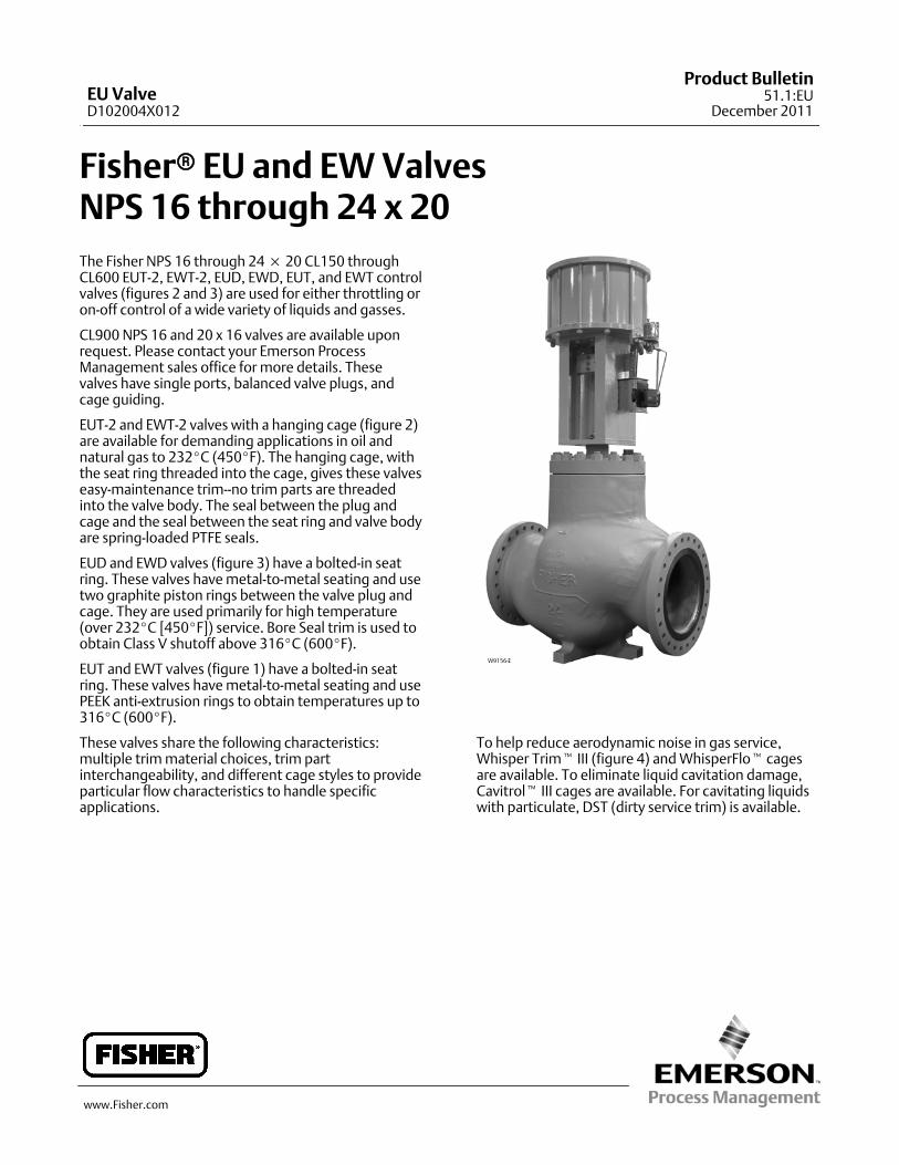
Fisherr EU and EWValvesNPS 16 through 24 x 20The Fisher NPS 16 through 24× 20 CL150 throughCL600 EUT-2, EWT-2, EUD, EWD, EUT, and EWT controlvalves (figures 2 and 3) are used for either throttling oron-off control of a wide variety of liquids and gasses.
CL900 NPS 16 and 20 x 16 valves are available uponrequest. Please contact your Emerson ProcessManagement sales office for more details. Thesevalves have single ports, balanced valve plugs, andcage guiding.
EUT-2 and EWT-2 valves with a hanging cage (figure 2)are available for demanding applications in oil andnatural gas to 232_C (450_F). The hanging cage, withthe seat ring threaded into the cage, gives these valveseasy-maintenance trim--no trim parts are threadedinto the valve body. The seal between the plug andcage and the seal between the seat ring and valve bodyare spring-loaded PTFE seals.
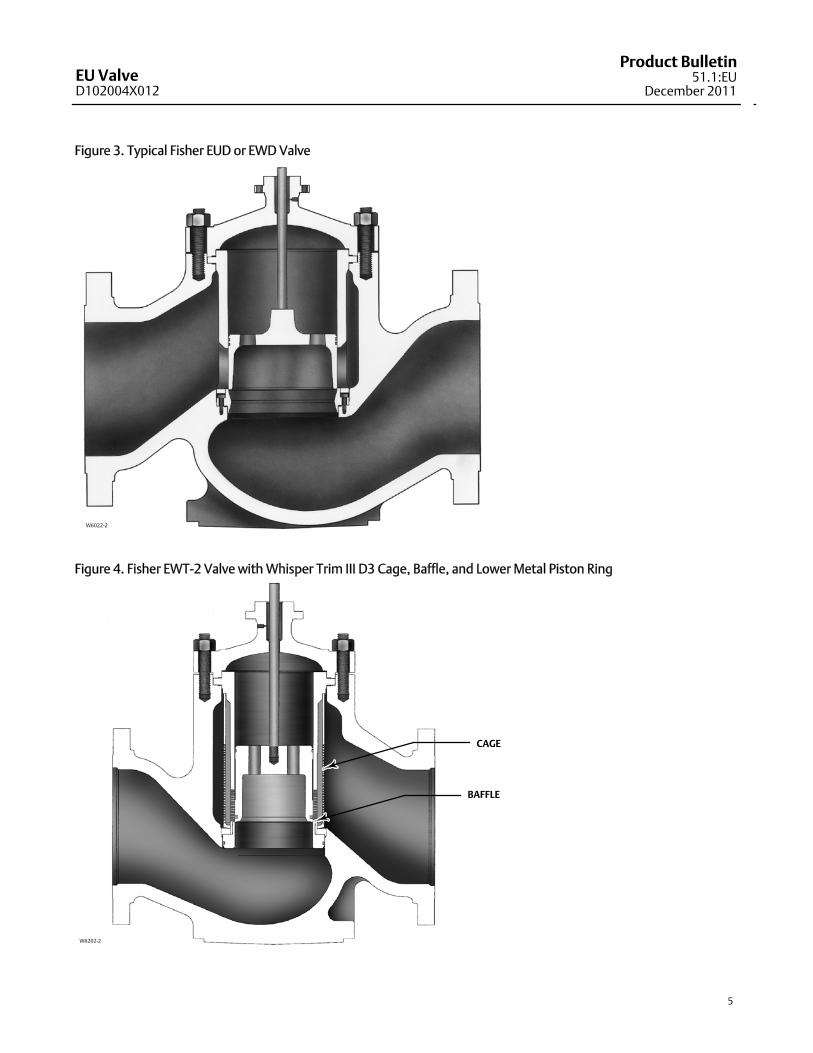
EUD and EWD valves (figure 3) have a bolted-in seatring. These valves havemetal-to-metal seating and usetwo graphite piston rings between the valve plug andcage. They are used primarily for high temperature(over 232_C [450_F]) service. Bore Seal trim is used toobtain Class V shutoff above 316_C (600_F).
EUT and EWT valves (figure 1) have a bolted-in seatring. These valves havemetal-to-metal seating and usePEEK anti-extrusion rings to obtain temperatures up to316_C (600_F).
These valves share the following characteristics:multiple trimmaterial choices, trim partinterchangeability, and different cage styles to provideparticular flow characteristics to handle specificapplications.
W9156-2
To help reduce aerodynamic noise in gas service,Whisper Trimt III (figure 4) andWhisperFlot cagesare available. To eliminate liquid cavitation damage,Cavitrolt III cages are available. For cavitating liquidswith particulate, DST (dirty service trim) is available.
EU ValveD102004X012
Product Bulletin51.1:EU
December 2011

EU ValveD102004X012
Product Bulletin51.1:EUDecember 2011
2
Specifications
Valve Sizes
EUT-2, EUD, and EUT:J NPS 16 andJ 20EWT-2, EWD, and EWT:J NPS 20 x 16,J 24 x 16, andJ 24 x 20 valves (size designationsare end connection size x nominal trim size)
End Connection Styles
Flanged: CL150, 300, and 600 raised-face or ring-typejoint flanges per ASME B16.5Buttwelding: All ASME B16.25 schedules throughschedule 120 that are compatible with the ASMEB16.34 valve body rating
For other end connections, contact your EmersonProcess Management sales office for details.
Maximum Inlet Pressure(1)
Flanged: Consistent with CL150, 300, and 600pressure-temperature ratings per ASME B16.34Buttwelding: Consistent with CL600 perASME B16.34
Material Temperature and Pressure DropCapabilities(1)
See table 1 and figures 5 and 6.
Shutoff Classifications per ANSI/FCI 70-2 and IEC60534-4
EUT and EWTwith Metal SeatsStandard: Class VEUT-2 and EWT-2 with Metal SeatsStandard (for all trims except 2-Stage Cavitrol Trim):Class IVStandard (for 2-Stage Cavitrol Trim): Class VOptional (for all trims except 2-Stage Cavitrol Trim):Class VEUT-2 and EWT-2 with Soft Metal SeatsClass VEUD and EWDwith Metal SeatsStandard: Class IIIOptional: Class IV and V
ConstructionMaterials
Valve Body and Bonnet:J WCC steel,JWC9 steel,J LCC steel, orJ CF8M (316 stainless steel). Forother materials, consult your Emerson ProcessManagement sales officeTrim and Other Parts: See tables 1, 2, and 3.
Flow Characteristics
Standard Cages:J Linear orJ equal percentageWhisper Trim III and Cavitrol III Cages: LinearWhisperFlo Cages: Linear
For other characteristics, contact your EmersonProcess Management sales office for details.
FlowDirection
Standard and Cavitrol III Cages: DownWhisper Trim III Cages: UpWhisperFlo Cages: Up
Flow Coefficients
See the section titled Coefficients in this bulletin, orFisher Catalog 12
Port Diameters
See tables 4 and 5
Valve Plug Travel
102 through 432mm (4 to 17 inches).
Contact your Emerson Process Management salesoffice for further details if needed
Yoke Boss and StemDiameters
J 127mm (5-inch) orJ 127mm (5H-inch) diameteryoke boss, each with 31.8mm(1.25 inch) diameter valve stem
Typical Bonnet Style
Standard Plain (style 1 extension)
ApproximateWeights
See figure 71. The pressure/temperature limits in this bulletin and any applicable standard or code limitation for valve should not be exceeded.
Table of ContentsSpecifications 2. . . . . . . . . . . . . . . . . . . . . . . . . . . . . . .Features 3. . . . . . . . . . . . . . . . . . . . . . . . . . . . . . . . . . . .
Coefficients 12. . . . . . . . . . . . . . . . . . . . . . . . . . . . . . . .

EU ValveD102004X012
Product Bulletin51.1:EU
December 2011
3
Figure 1. Fisher EUT / EWT Valve with PEEK Anti-Extrusion Rings
W9518-1
Features Stable Control at High Pressure Drops– Ruggedcage guiding stabilizes the valve plug at all points inits travel range. This guiding reduces vibration,mechanical noise, and the need for hydraulicsnubbers.
Economy– Streamlined flow passages providegreater capacities per initial investment thanmost
globe valves of the same size. Balanced valve plugdesign can allow use of smaller actuators for highpressure drops.
Cost-Effective Operation– Increased wearresistance of the standard hardened stainless steeltrimmeans long-lasting service.
Easy Maintenance– The valve can stay in thepipeline during removal of trim parts for inspectionormaintenance.

EU ValveD102004X012
Product Bulletin51.1:EUDecember 2011
4
Figure 2. Typical Fisher EUT-2 or EWT-2 Valve
W6088-2
W6089-1A
COMPLETE VALVE
SEAT RING SEAL DETAIL
SEAL RING
HANGING CAGE DESIGN
TAPPED BONNET(OPTIONAL)
BONNET GASKETCAGE GASKET
SEAT RINGTHREADEDTO CAGE
SEAT RINGTHREADEDTO CAGE
EU ValveD102004X012
Product Bulletin51.1:EU
December 2011
5
Figure 3. Typical Fisher EUD or EWD Valve
W6022-2
Figure 4. Fisher EWT-2 Valve with Whisper Trim III D3 Cage, Baffle, and Lower Metal Piston Ring
W6202-2
CAGE
BAFFLE

EU ValveD102004X012
Product Bulletin51.1:EUDecember 2011
6
Table 1. Construction Materials
PART MATERIALTEMPERATURE
_C _F
Valve Body and Bonnet
WCC SteelWC9 Steel
CF8M (316 Stainless Steel)LCC
-29 to 427-29 to 593-198 to 593-46 to 343
-20 to 800-20 to 1100-325 to 1000-50 to 650
Cage, Seat Ring, and Valve Plug See tables 2 and 3 See figures 5 and 6
Soft Metal Seat (with trim 233 in EUT-2 and EWT-2valves only)
CF8M See figures 5 and 6
Valve Stem S20910 SST Not a Limiting Factor
Valve-to-BonnetBolting
WCC ValveSA-193-B7 Studs
-29 to 427 -20 to 800SA-194-2HNuts
LCC ValveSA-193-B7 Studs
-46 to 343 -50 to 650SA-194-2HNuts
WC9 ValveSA-193-B7 Studs
-29 to 427 -20 to 800SA-194-2HNuts
CF8MValve
S20910 CrCt Studs-198 to 538 -325 to 1000
S20910 Nuts
B8M Class 2 studs-198 to 427 -325 to 800
8M nuts
SA-193-B7 Studs-29 to 427 -20 to 800
SA-194-2HNuts
Seat Ring Cap ScrewsS17400N07718
-29 to 354-198 to 593
-20 to 700-325 to 1100
Bonnet, Seat Ring, and Cage Gaskets N06600/GraphiteOxidizing -198 to 427 -325 to 800
Non-Oxidizing -198 to 593 -325 to 1100
EUD and EWD Piston Ring or Lower GraphitePiston Ring (254mm [10 inch] port only)
Graphite (FisherDesignation FMS
17F27)
Oxidizing -198 to 427 -325 to 800
Non-Oxidizing -198 to 482 -325 to 900
Graphite (FisherDesignation FMS
17F39)
Oxidizing -198 to 538 -325 to 1000
Non-Oxidizing -198 to 593 -325 to 1100
EUD and EWD Bore Seal N07718 -198 to 593 -325 to 1100
EUT-2 and EWT-2 Seat Ring Seal Ringand Plug Seal Ring
N10276/Glass andMoly-Filled PTFE -73 to 232 -100 to 450
EUT and EWT valveswith PEEK
anti-extrusion rings
Backup ringS41000
Not a Limiting Factor Not a Limiting FactorS31600
Retaining ring 18-8
Seal ring PTFE/graphite with N10276 spring 232 to 316 450 to 600
For applications using alowermetal piston ring
Lowermetal piston ring Iron / N07750 -73 to 427 -100 to 800
Packing (Temperatures shown are in-bodytemperatures with plain bonnet.)
PTFE V-Ring -46 to 232 -50 to 450
PTFE Composition -46 to 232 -50 to 450
GraphiteRibbon/Filament
Oxidizing -198 to 354 -325 to 700
Non-Oxidizing -198 to 538 -325 to 1000
Packing Flange, Studs, and NutsSteel -29 to 427 -20 to 800
S31600 (316 Stainless Steel) -198 to 593 -325 to 1100
Packing Follower, Spring (PTFE V-Ring Packing), orLantern Ring
S31600 Not a Limiting Factor
Packing Box RingS17400 -101 to 427 -150 to 800
S31600 -198 to 593 -325 to 1100
EU ValveD102004X012
Product Bulletin51.1:EU
December 2011
7
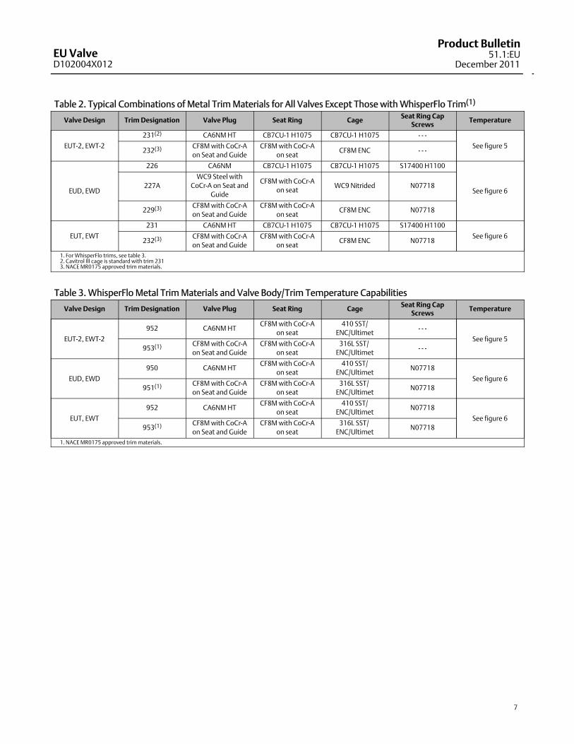
Table 2. Typical Combinations of Metal TrimMaterials for All Valves Except Those withWhisperFlo Trim(1)
Valve Design TrimDesignation Valve Plug Seat Ring Cage Seat Ring CapScrews
Temperature
EUT-2, EWT-2
231(2) CA6NMHT CB7CU-1 H1075 CB7CU-1 H1075 - - -
See figure 5232(3)
CF8Mwith CoCr-Aon Seat and Guide
CF8Mwith CoCr-Aon seat
CF8M ENC - - -
EUD, EWD
226 CA6NM CB7CU-1 H1075 CB7CU-1 H1075 S17400 H1100
See figure 6227A
WC9 Steel withCoCr-A on Seat and
Guide
CF8Mwith CoCr-Aon seat
WC9 Nitrided N07718
229(3)CF8Mwith CoCr-Aon Seat and Guide
CF8Mwith CoCr-Aon seat
CF8M ENC N07718
EUT, EWT
231 CA6NMHT CB7CU-1 H1075 CB7CU-1 H1075 S17400 H1100
See figure 6232(3)
CF8Mwith CoCr-Aon Seat and Guide
CF8Mwith CoCr-Aon seat
CF8M ENC N07718
1. ForWhisperFlo trims, see table 3.2. Cavitrol III cage is standard with trim 2313. NACEMR0175 approved trimmaterials.
Table 3. WhisperFlo Metal TrimMaterials and Valve Body/Trim Temperature Capabilities
Valve Design TrimDesignation Valve Plug Seat Ring Cage Seat Ring CapScrews
Temperature
EUT-2, EWT-2
952 CA6NMHTCF8Mwith CoCr-A
on seat410 SST/
ENC/Ultimet- - -
See figure 5953(1)
CF8Mwith CoCr-Aon Seat and Guide
CF8Mwith CoCr-Aon seat
316L SST/ENC/Ultimet
- - -
EUD, EWD
950 CA6NMHTCF8Mwith CoCr-A
on seat410 SST/
ENC/UltimetN07718
See figure 6951(1)
CF8Mwith CoCr-Aon Seat and Guide
CF8Mwith CoCr-Aon seat
316L SST/ENC/Ultimet
N07718
EUT, EWT
952 CA6NMHTCF8Mwith CoCr-A
on seat410 SST/
ENC/UltimetN07718
See figure 6953(1)
CF8Mwith CoCr-Aon Seat and Guide
CF8Mwith CoCr-Aon seat
316L SST/ENC/Ultimet
N07718
1. NACEMR0175 approved trimmaterials.
EU ValveD102004X012
Product Bulletin51.1:EUDecember 2011
8
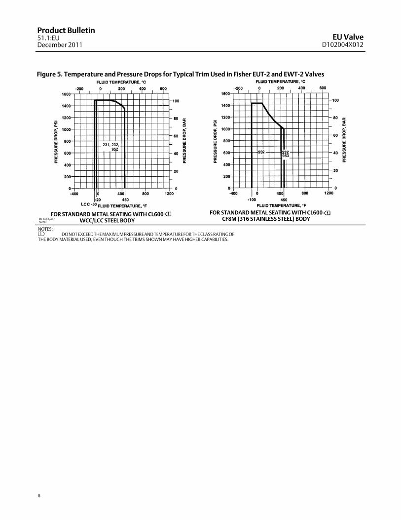
Figure 5. Temperature and Pressure Drops for Typical TrimUsed in Fisher EUT-2 and EWT-2 Valves
MC140-1/AR 1A6890
NOTES:DONOTEXCEEDTHEMAXIMUMPRESSUREANDTEMPERATUREFORTHECLASSRATINGOF
THE BODYMATERIAL USED, EVEN THOUGH THE TRIMS SHOWNMAYHAVE HIGHER CAPABILITIES.1
FOR STANDARDMETAL SEATINGWITH CL600WCC/LCC STEEL BODY
FOR STANDARDMETAL SEATINGWITH CL600CF8M (316 STAINLESS STEEL) BODY

EU ValveD102004X012
Product Bulletin51.1:EU
December 2011
9
Figure 6. Temperature and Pressure Drops for Typical Trim Used in Fisher EUD, EWD, EUT, and EWT Valves
MC140-2/AR 1A6891
3
231, 232
952, 953
NOTES:482_C (900_F) LIMIT --WCC STEEL VALVE PLUG371_C (700_F) LIMIT -- S17400 SEAT RING BOLTING316_C (600_F) LIMIT -- EUT AND EWTVALVESWITH 231, 232, 952, AND 953 TRIMS
DONOTEXCEEDTHEMAXIMUMPRESSUREANDTEMPERATURE FORTHECLASS RATINGOFTHEBODYMATERIALUSED, EVENTHOUGHTHETRIMS SHOWNMAYHAVE HIGHER CAPABILITIES.
1
32
FOR STANDARDMETAL SEATINGWITH CL600CF8M (316 STAINLESS STEEL) BODY
FOR STANDARDMETAL SEATINGWITH CL600WCC STEEL BODY
FOR STANDARDMETAL SEATINGWITH CL600WC9 CHROMEMOLY STEEL BODY

EU ValveD102004X012
Product Bulletin51.1:EUDecember 2011
10
Table 4. Port Diameters for Fisher EUT-2 and EWT-2 CL 150 through CL600 Valves
Valve Size, NPS TRIMPORT DIAMETER
mm Inches
16
Cast cages(1), WhisperFlo, and Cav III 374.7 14.75
Whisper Trim III A, B, and C 412.8 16.25
Whisper Trim III D 355.6 14.00
20× 16
Cast cages(1), WhisperFlo, and Cav III 374.7 14.75
Drilled cages(1) andWhisper Trim III A, B, and C 412.8 16.25
Whisper Trim III D 355.6 14.00
24× 16
Cast cages(1), WhisperFlo, and Cav III 374.7 14.75
Drilled cages(1) andWhisper Trim III A, B, and C 412.8 16.25
Whisper Trim III D 355.6 14.00
20
WhisperFlo and Cav III 463.6 18.25
Drilled cages(1) andWhisper Trim III A, B, and C 501.7 19.75
Whisper Trim III D 431.8 17.00
24× 20
WhisperFlo and Cav III 463.6 18.25
Drilled cages(1) andWhisper Trim III A, B, and C 501.7 19.75
Whisper Trim III D 431.8 17.001. Linear or equal percentage.
Table 5. Port Diameters for Fisher EUD, EWD, EUT and EWT CL 150 through CL600 Valves
Valve Size, NPS TRIMPORT DIAMETER
mm Inches
16
Linear; Equal Percentage; Whisper Trim III A, B,and C;WhisperFlo; and Cav III
374.7 14.75
Whisper Trim III D 355.6 14.00
20× 16
Linear; Equal Percentage; Whisper Trim III A, B,and C;WhisperFlo; and Cav III
374.7 14.75
Whisper Trim III D 355.6 14.00
24× 16
Linear; Equal Percentage; Whisper Trim III A, B,and C;WhisperFlo; and Cav III
374.7 14.75
Whisper Trim III D 355.6 14.00
20
Linear; Equal Percentage; Whisper Trim III A, B,and C;WhisperFlo; and Cav III
463.6 18.25
Whisper Trim III D 431.8 17.00
24× 20
Linear; Equal Percentage; Whisper Trim III A, B,and C;WhisperFlo; and Cav III
463.6 18.25
Whisper Trim III D 431.8 17.00

EU ValveD102004X012
Product Bulletin51.1:EU
December 2011
11
Table 6. Dimensions and ApproximateWeights
ENDCONNECTION
APPROXIMATEWEIGHT
(LONG-NECKVALVE(2)
DIMENSION
A
G
Standard Plain Bonnet (Style 1 Extension)
CL150 CL300 CL600Short-Neck Valve(2) Long-Neck Valve(2)
D Max. Travel D Max. Travel
Size,NPS
Type(1) Kg Lb mm Inch mm Inch mm Inch mm Inch mm Inch mm Inch mm Inch mm Inch
16
RF2540 5600
1016 40.00 1057 41.62 1108 43.62
437 17.19 663 26.12 127 5.00 816 32.12 226 8.88RTJ 1026 40.38 1073 42.25 1111 43.75
BW 2270 5000 - - - - - - - - - - - - 1108 43.62
20× 16
RF3540 7800
1267 49.88 1308 51.50 1372 54.00
487 19.19 706 27.81 226 8.88 859 33.81 276 10.88RTJ 1276 50.25 1327 52.25 1378 54.25
BW 3130 6900 - - - - - - - - - - - - 1372 54.00
20
RF5220 11500
1267 49.88 1308 51.50 1372 54.00
514 20.25 917 36.12 276 10.88 1121 44.12 378 14.88RTJ - - - - - - - - - - - - - - - - - -
BW 4810 10600 - - - - - - - - - - - - 1372 54.00
24× 16
RF5220 11500
1556 61.25 1600 63.00 1676 66.00
526 20.69 816 32.12 226 8.88 1121 44.12 378 14.88RTJ 1565 61.62 1623 63.88 1686 66.38
BW 4630 10200 - - - - - - - - - - - - 1676 66.00
24× 20
RF7710 17000
1556 61.25 1600 63.00 1676 66.00
565 22.25 917 36.12 276 10.88 1121 44.12 378 14.88RTJ 1565 61.62 1623 63.88 1686 66.38
BW 7120 15700 - - - - - - - - - - - - 1676 66.00
1. RF--raised face; RTJ--ring-type joint; BW--buttwelding.2. For longer travels, the neck of the valve (the portion of the valve body that supports the bonnet) is longer to accommodate the travel. The longer neck increases the D dimension.
Figure 7. Dimensions and ApproximateWeights (also see table 6)
A6068
31.8(1.25)STEMDIAMETER
25(1.00)
mm(INCH)
MATCH LINE FOR 585C ACTUATORSAND 657, 667, SIZE 100 ACTUATORS
MATCH LINEFOR ALL OTHERACTUATORS
D
G
A
A2

EU ValveD102004X012
Product Bulletin51.1:EUDecember 2011
12
CoefficientsTable 7. Fisher EUT-2, EUD, and EUT; CL150, 300, and 600; Linear; Flow Down
Linear LinearCharacteristic
ValveType
ValveSize,NPS
PortDiameter
TotalTravel
Con-struc-tion(1)
FlowCoeffi-cient
Valve Opening–Percent of Total TravelFL
mm Inches mm Inches Min(2) 10 20 30 40 50 60 70 80 90 100
EUT-2,EUD, EUT
16
374.7 14.75 102 4.00 SNC
Cv 46 270 520 790 1080 1380 1690 1980 2240 2450 2630 0.88
Kv 39.8 234 450 683 934 1194 1462 1713 1938 2119 2275 - - -
XT 0.391 0.643 0.684 0.667 0.645 0.650 0.664 0.694 0.721 0.749 0.755 - - -
374.7 14.75 127 5.00 SNC
Cv 46 335 650 1000 1380 1770 2120 2410 2630 2780 2860 0.88
Kv 39.8 290 562 865 1194 1531 1834 2085 2275 2405 2474 - - -
XT 0.391 0.650 0.677 0.652 0.650 0.666 0.709 0.745 0.755 0.739 0.763 - - -
EUD, EUT 20
436.6 18.25 203 8.00 SND
Cv 56 315 625 920 1230 1570 1920 2260 2530 2800 3010 0.89
Kv 48.4 272 541 796 1064 1358 1661 1955 2188 2422 2604 - - -
XT 0.391 0.655 0.653 0.673 0.671 0.649 0.650 0.650 0.663 0.667 0.684 - - -
463.6 18.25 276 10.88 SND
Cv 56 255 670 1030 1460 1930 2370 2780 3100 3390 3650 0.89
Kv 48.4 221 580 891 1263 1669 2050 2405 2682 2932 3157 - - -
XT 0.391 0.648 0.656 0.681 0.656 0.649 0.653 0.667 0.690 0.719 0.733 - - -
463.6 18.25 378 14.88 LND
Cv 56 375 865 1370 1940 2460 2910 3330 3700 4000 4220 0.89
Kv 48.4 324 748 1185 1678 2128 2517 2880 3201 3460 3650 - - -
XT 0.391 0.651 0.674 0.668 0.651 0.661 0.676 0.707 0.736 0.755 0.748 - - -
EUT-2 20
501.7 19.75 203 8.00 SND
Cv 60 340 675 990 1340 1710 2110 2420 2720 2960 3180 0.89
Kv 51.9 294 584 856 1159 1479 1825 2093 2353 2560 2751 - - -
XT 0.391 0.654 0.664 0.682 0.668 0.656 0.647 0.659 0.665 0.681 0.694 - - -
501.7 19.75 276 10.88 SND
Cv 60 465 905 1370 1880 2360 2760 3080 3350 3610 3830 0.89
Kv 51.9 402 783 1185 1626 2041 2387 2664 2898 3123 3313 - - -
XT 0.391 0.650 0.673 0.665 0.654 0.657 0.669 0.685 0.711 0.726 0.742 - - -
501.7 19.75 378 14.88 LND
Cv 60 410 935 1500 2130 2650 3070 3510 3870 4150 4340 0.89
Kv 51.9 355 809 1298 1842 2292 2656 3036 3348 3590 3754 - - -
XT 0.391 0.648 0.678 0.659 0.648 0.661 0.690 0.718 0.749 0.753 0.737 - - -
EU ValveD102004X012
Product Bulletin51.1:EU
December 2011
13
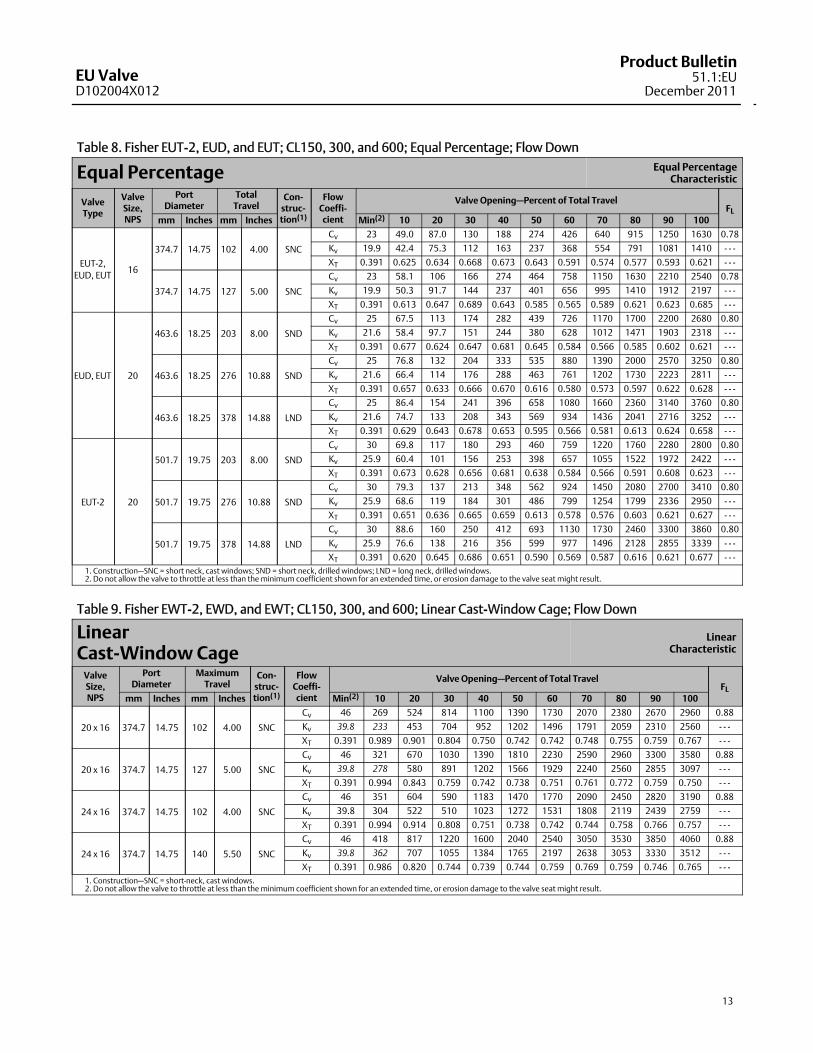
Table 8. Fisher EUT-2, EUD, and EUT; CL150, 300, and 600; Equal Percentage; Flow Down
Equal Percentage Equal PercentageCharacteristic
ValveType
ValveSize,NPS
PortDiameter
TotalTravel
Con-struc-tion(1)
FlowCoeffi-cient
Valve Opening–Percent of Total TravelFL
mm Inches mm Inches Min(2) 10 20 30 40 50 60 70 80 90 100
EUT-2,EUD, EUT
16
374.7 14.75 102 4.00 SNC
Cv 23 49.0 87.0 130 188 274 426 640 915 1250 1630 0.78
Kv 19.9 42.4 75.3 112 163 237 368 554 791 1081 1410 - - -
XT 0.391 0.625 0.634 0.668 0.673 0.643 0.591 0.574 0.577 0.593 0.621 - - -
374.7 14.75 127 5.00 SNC
Cv 23 58.1 106 166 274 464 758 1150 1630 2210 2540 0.78
Kv 19.9 50.3 91.7 144 237 401 656 995 1410 1912 2197 - - -
XT 0.391 0.613 0.647 0.689 0.643 0.585 0.565 0.589 0.621 0.623 0.685 - - -
EUD, EUT 20
463.6 18.25 203 8.00 SND
Cv 25 67.5 113 174 282 439 726 1170 1700 2200 2680 0.80
Kv 21.6 58.4 97.7 151 244 380 628 1012 1471 1903 2318 - - -
XT 0.391 0.677 0.624 0.647 0.681 0.645 0.584 0.566 0.585 0.602 0.621 - - -
463.6 18.25 276 10.88 SND
Cv 25 76.8 132 204 333 535 880 1390 2000 2570 3250 0.80
Kv 21.6 66.4 114 176 288 463 761 1202 1730 2223 2811 - - -
XT 0.391 0.657 0.633 0.666 0.670 0.616 0.580 0.573 0.597 0.622 0.628 - - -
463.6 18.25 378 14.88 LND
Cv 25 86.4 154 241 396 658 1080 1660 2360 3140 3760 0.80
Kv 21.6 74.7 133 208 343 569 934 1436 2041 2716 3252 - - -
XT 0.391 0.629 0.643 0.678 0.653 0.595 0.566 0.581 0.613 0.624 0.658 - - -
EUT-2 20
501.7 19.75 203 8.00 SND
Cv 30 69.8 117 180 293 460 759 1220 1760 2280 2800 0.80
Kv 25.9 60.4 101 156 253 398 657 1055 1522 1972 2422 - - -
XT 0.391 0.673 0.628 0.656 0.681 0.638 0.584 0.566 0.591 0.608 0.623 - - -
501.7 19.75 276 10.88 SND
Cv 30 79.3 137 213 348 562 924 1450 2080 2700 3410 0.80
Kv 25.9 68.6 119 184 301 486 799 1254 1799 2336 2950 - - -
XT 0.391 0.651 0.636 0.665 0.659 0.613 0.578 0.576 0.603 0.621 0.627 - - -
501.7 19.75 378 14.88 LND
Cv 30 88.6 160 250 412 693 1130 1730 2460 3300 3860 0.80
Kv 25.9 76.6 138 216 356 599 977 1496 2128 2855 3339 - - -
XT 0.391 0.620 0.645 0.686 0.651 0.590 0.569 0.587 0.616 0.621 0.677 - - -1. Construction–SNC = short neck, cast windows; SND = short neck, drilled windows; LND = long neck, drilled windows.2. Do not allow the valve to throttle at less than theminimum coefficient shown for an extended time, or erosion damage to the valve seat might result.
Table 9. Fisher EWT-2, EWD, and EWT; CL150, 300, and 600; Linear Cast-Window Cage; Flow Down
LinearCast-Window Cage
LinearCharacteristic
ValveSize,NPS
PortDiameter
MaximumTravel
Con-struc-tion(1)
FlowCoeffi-cient
Valve Opening–Percent of Total TravelFL
mm Inches mm Inches Min(2) 10 20 30 40 50 60 70 80 90 100
20 x 16 374.7 14.75 102 4.00 SNC
Cv 46 269 524 814 1100 1390 1730 2070 2380 2670 2960 0.88
Kv 39.8 233 453 704 952 1202 1496 1791 2059 2310 2560 - - -
XT 0.391 0.989 0.901 0.804 0.750 0.742 0.742 0.748 0.755 0.759 0.767 - - -
20 x 16 374.7 14.75 127 5.00 SNC
Cv 46 321 670 1030 1390 1810 2230 2590 2960 3300 3580 0.88
Kv 39.8 278 580 891 1202 1566 1929 2240 2560 2855 3097 - - -
XT 0.391 0.994 0.843 0.759 0.742 0.738 0.751 0.761 0.772 0.759 0.750 - - -
24 x 16 374.7 14.75 102 4.00 SNC
Cv 46 351 604 590 1183 1470 1770 2090 2450 2820 3190 0.88
Kv 39.8 304 522 510 1023 1272 1531 1808 2119 2439 2759 - - -
XT 0.391 0.994 0.914 0.808 0.751 0.738 0.742 0.744 0.758 0.766 0.757 - - -
24 x 16 374.7 14.75 140 5.50 SNC
Cv 46 418 817 1220 1600 2040 2540 3050 3530 3850 4060 0.88
Kv 39.8 362 707 1055 1384 1765 2197 2638 3053 3330 3512 - - -
XT 0.391 0.986 0.820 0.744 0.739 0.744 0.759 0.769 0.759 0.746 0.765 - - -1. Construction–SNC = short-neck, cast windows.2. Do not allow the valve to throttle at less than theminimum coefficient shown for an extended time, or erosion damage to the valve seat might result.

EU ValveD102004X012
Product Bulletin51.1:EUDecember 2011
14
Table 10. Fisher EWT-2, EWD, and EWT; CL150, 300, and 600; Linear Drilled-Window Cage; Flow Down
LinearDrilled-Window Cage
LinearCharacteristic
ValveType
ValveSize,NPS
PortDiameter
MaximumTravel
Con-struc-tion(1)
FlowCoeffi-cient
Valve Opening–Percent of Total TravelFL
mm Inches mm Inches Min(2) 10 20 30 40 50 60 70 80 90 100
EWD,EWT
20 x 16 374.7 14.75 276 10.88 LND
Cv 46 262 550 874 1200 1560 1850 2190 2470 2760 3040 0.89
Kv 39.8 227 476 756 1038 1349 1600 1894 2137 2387 2630 - - -
XT 0.391 0.985 0.894 0.791 0.740 0.738 0.743 0.745 0.758 0.762 0.760 - - -
20 x 16 374.7 14.75 378 14.88 LN-SD
Cv 46 330 742 1160 1570 1970 2370 2740 3110 3430 3660 0.89
Kv 39.8 285 642 1003 1358 1704 2050 2370 2690 2967 3166 - - -
XT 0.391 0.985 0.815 0.739 0.739 0.740 0.754 0.764 0.768 0.752 0.753 - - -
EWT-2
20 x 16 412.8 16.25 276 10.88 LND
Cv 52 322 679 1080 1480 1880 2210 2570 2880 3180 3480 0.89
Kv 45.0 279 587 934 1280 1626 1912 2223 2491 2751 3010 - - -
XT 0.391 0.988 0.888 0.786 0.742 0.738 0.759 0.744 0.754 0.762 0.768 - - -
20 x 16 412.8 16.25 378 14.88 LN-SD
Cv 52 390 868 1350 1850 2340 2810 3240 3670 4060 4370 0.89
Kv 45.0 337 751 1168 1600 2024 2431 2803 3175 3512 3780 - - -
XT 0.391 0.990 0.823 0.751 0.736 0.742 0.754 0.760 0.760 0.754 0.746 - - -
EWD,EWT
24 x 16 374.7 14.75 378 14.88 LND
Cv 46 328 701 1140 1610 2060 2480 2860 3140 3340 3490 0.89
Kv 39.8 284 606 986 1393 1782 2145 2474 2716 2889 3019 - - -
XT 0.391 0.997 0.934 0.828 0.767 0.745 0.734 0.743 0.753 0.767 0.764 - - -
24 x 16 374.7 14.75 429 16.88 LN-SD
Cv 46 356 764 1240 1750 2210 2620 3030 3300 3500 3670 0.89
Kv 39.8 308 661 1073 1514 1912 2266 2621 2855 3028 3175 - - -
XT 0.391 0.994 0.919 0.816 0.757 0.743 0.741 0.751 0.759 0.759 0.748 - - -
EWT-2
24 x 16 412.8 16.25 378 14.88 LND
Cv 52 363 765 1240 1750 2280 2740 3260 3670 3960 4150 0.89
Kv 45.0 314 662 1073 1514 1972 2370 2820 3175 3425 3590 - - -
XT 0.391 0.997 0.955 0.853 0.787 0.745 0.739 0.738 0.748 0.759 0.763 - - -
24 x 16 412.8 16.25 429 16.88 LN-SD
Cv 52 393 832 1350 1900 2440 2940 3480 3850 4110 4310 0.89
Kv 45.0 340 720 1168 1644 2111 2543 3010 3330 3555 3728 - - -
XT 0.391 0.997 0.942 0.834 0.775 0.746 0.738 0.743 0.757 0.767 0.757 - - -
EWD,EWT
24 x 20 463.6 18.25 378 14.88 LND
Cv 56 457 995 1560 2130 2640 3190 3660 4110 4560 4970 0.89
Kv 48.4 395 861 1349 1842 2284 2759 3166 3555 3944 4299 - - -
XT 0.391 0.991 .0850 0.763 0.738 0.739 0.743 0.753 0.757 0.769 0.766 - - -
24 x 20 463.6 18.25 429 16.88 LN-SD
Cv 56 490 1080 1680 2300 2920 3440 3970 4510 5000 5440 0.89
Kv 48.4 424 934 1453 1990 2526 2976 3434 3901 4325 4706 - - -
XT 0.391 0.990 0.832 0.753 0.735 0.733 0.748 0.755 0.767 0.766 0.754 - - -
EWT-2
24 x 20 501.7 19.75 378 14.88 LND
Cv 60 502 1070 1690 2300 2900 3500 4020 4480 4960 5420 0.89
Kv 51.9 434 926 1462 1990 2509 3028 3477 3875 4290 4688 - - -
XT 0.391 0.992 0.873 0.775 0.743 0.736 0.735 0.747 0.758 0.760 0.768 - - -
24 x 20 501.7 19.75 429 16.88 LN-SD
Cv 60 591 1320 2050 2790 3470 4190 4830 5470 6060 6500 0.89
Kv 51.9 511 1142 1773 2413 3002 3624 4178 4732 5242 5623 - - -
XT 0.391 0.988 0.816 0.741 0.735 0.747 0.748 0.765 0.770 0.758 0.749 - - -1. Construction–LND - long neck, drilled windows; LN-SD = long neck with bonnet spacer, drilled windows.2. Do not allow the valve to throttle at less than theminimum coefficient shown for an extended time, or erosion damage to the valve seat might result.

EU ValveD102004X012
Product Bulletin51.1:EU
December 2011
15
Table 11. Fisher EWT-2, EWD, and EWT; CL150, 300, and 600; Equal Percentage Cast-Window Cage; Flow Down
Equal PercentageCast-Window Cage
Equal PercentageCharacteristic
ValveSize,NPS
PortDiameter
MaximumTravel
Con-struc-tion(1)
FlowCoeffi-cient
Valve Opening–Percent of Total TravelFL
mm Inches mm Inches Min(2) 10 20 30 40 50 60 70 80 90 100
20 x 16 374.7 14.75 102 4.00 SNC
Cv 23 29.8 61.3 99.1 152 233 355 544 818 1180 1630 0.88
Kv 19.9 25.8 53.0 85.7 131 202 307 471 708 1021 1410 - - -
XT 0.391 0.997 0.990 0.993 0.990 0.987 0.986 0.896 0.802 0.744 0.735 - - -
20 x 16 374.7 14.75 127 5.00 SNC
Cv 23 37.2 77.4 132 233 388 652 1070 1630 2080 2460 0.88
Kv 19.9 32.2 67.0 114 202 336 564 926 1410 1799 2128 - - -
XT 0.391 0.989 0.990 0.989 0.987 0.959 0.847 0.751 0.735 0.747 0.755 - - -
20 x 16 374.7 14.75 140 5.50 SNC
Cv 23 41.2 88.2 162 293 517 900 1470 2000 2420 2830 0.88
Kv 19.9 35.6 76.3 140 253 447 779 1272 1730 2093 2448 - - -
XT 0.391 0.990 0.990 0.991 0.987 0.907 0.785 0.741 0.742 0.757 0.762 - - -
24 x 16 374.7 14.75 102 4.00 SNC
Cv 23 38.9 79.8 128 195 296 444 646 922 1290 1700 0.88
Kv 19.9 33.6 69.0 111 169 256 384 559 798 1116 1471 - - -
XT 0.391 0.992 0.992 0.996 0.995 0.993 0.982 0.899 0.801 0.744 0.735 - - -
24 x 16 374.7 14.75 127 5.00 SNC
Cv 23 48.6 100 170 296 480 753 1180 1700 2130 2580 0.88
Kv 19.9 42.0 86.5 147 256 415 651 1021 1471 1842 2232 - - -
XT 0.391 0.986 0.990 0.991 0.993 0.969 0.852 0.751 0.735 0.742 0.757 - - -
24 x 16 374.7 14.75 140 5.50 SNC
Cv 23 53.8 114 208 371 619 1010 1560 2030 2530 3040 0.88
Kv 19.9 46.5 98.6 180 321 535 874 1349 1756 2188 2630 - - -
XT 0.391 0.989 0.990 0.993 0.995 0.908 0.781 0.732 0.745 0.758 0.774 - - -1. Construction–SNC = short-neck, cast windows.2. Do not allow the valve to throttle at less than theminimum coefficient shown for an extended time, or erosion damage to the valve seat might result.

EU ValveD102004X012
Product Bulletin51.1:EUDecember 2011
16
Table 12. Fisher EWT-2, EWD, and EWT; CL150, 300, and 600; Equal Percentage Drilled-Window Cage; Flow Down
Equal PercentageDrilled-Window Cage
Equal PercentageCharacteristic
ValveType
ValveSize,NPS
PortDiameter
MaximumTravel
Con-struc-tion(1)
FlowCoeffi-cient
Valve Opening–Percent of Total TravelFL
mm Inches mm Inches Min(2) 10 20 30 40 50 60 70 80 90 100
EWD,EWT
20 x 16 374.7 14.75 276 10.88 LND
Cv 23 42.8 93.5 170 278 445 750 1220 1810 2290 2700 0.89
Kv 19.9 37.0 80.9 147 240 385 649 1055 1566 1981 2336 - - -
XT 0.391 0.986 0.995 0.991 0.996 0.934 0.816 0.741 0.743 0.751 0.764 - - -
20 x 16 374.7 14.75 378 14.88 LN-SD
Cv 23 55.7 123 213 340 584 974 1580 2210 2750 3260 0.89
Kv 19.9 48.2 106 184 294 505 843 1367 1912 2379 2820 - - -
XT 0.391 0.993 0.995 0.995 0.985 0.879 0.771 0.735 0.751 0.762 0.764 - - -
EWT-2
20 x 16 412.8 16.25 276 10.88 LND
Cv 25 48.1 105 189 318 500 841 1370 2070 2640 3100 0.89
Kv 21.6 41.6 90.8 163 275 433 727 1185 1791 2284 2682 - - -
XT 0.391 0.996 0.990 0.995 0.997 0.951 0.833 0.748 0.739 0.744 0.759 - - -
20 x 16 412.8 16.25 378 14.88 LN-SD
Cv 25 65.9 146 253 403 691 1150 1880 2640 3280 3890 0.89
Kv 21.6 57.0 126 219 349 598 995 1626 2284 2837 3365 - - -
XT 0.391 0.995 0.990 0.996 0.985 0.885 0.783 0.736 0.746 0.737 0.754 - - -
EWD,EWT
24 x 16 374.7 14.75 378 14.88 LND
Cv 23 42.4 88.1 150 265 438 732 1250 2000 2650 3110 0.89
Kv 19.9 36.7 76.2 130 229 379 633 1081 1730 2292 2690 - - -
XT 0.391 0.993 0.998 0.997 0.995 0.998 0.928 0.814 0.746 0.755 0.764 - - -
24 x 16 374.7 14.75 429 16.88 LN-SD
Cv 23 46.8 97.4 166 293 484 820 1400 2210 2860 3270 0.89
Kv 19.9 40.5 84.3 144 253 419 709 1211 1912 2474 2829 - - -
XT 0.391 0.998 0.992 0.991 0.997 0.994 0.905 0.797 0.739 0.743 0.760 - - -
EWT-2
24 x 16 412.8 16.25 378 14.88 LND
Cv 25 49.6 103 176 311 513 853 1460 2350 3120 3700 0.89
Kv 21.6 42.9 89.1 152 269 444 738 1263 2033 2699 3201 - - -
XT 0.391 0.996 0.995 0.991 0.994 0.988 0.935 0.814 0.743 0.735 0.748 - - -
24 x 16 412.8 16.25 429 16.88 LN-SD
Cv 25 53.1 110 188 332 549 921 1580 2510 3290 3830 0.89
Kv 21.6 45.9 95.2 163 287 475 797 1367 2171 2846 3313 - - -
XT 0.391 0.996 0.995 0.995 0.988 0.995 0.918 0.802 0.742 0.737 0.754 - - -
EWD,EWT
24 x 20 463.6 18.25 378 14.88 LND
Cv 28 71.8 158 283 457 749 1260 2050 2990 3730 4430 0.89
Kv 24.2 62.1 137 245 395 648 1090 1773 2586 3226 3832 - - -
XT 0.391 0.992 0.987 0.996 0.991 0.918 0.801 0.739 0.742 0.759 0.765 - - -
24 x 20 463.6 18.25 429 16.88 LN-SD
Cv 28 81.5 180 315 501 854 1430 2330 3280 4070 4840 0.89
Kv 24.2 70.5 156 272 433 739 1237 2015 2837 3521 4187 - - -
XT 0.391 0.994 0.994 0.984 0.986 0.889 0.776 0.735 0.742 0.761 0.762 - - -
EWT-2
24 x 20 501.7 19.75 378 14.88 LND
Cv 30 76.1 166 302 496 792 1330 2170 3230 4080 4820 0.89
Kv 25.9 65.8 144 261 429 685 1150 1877 2794 3529 4169 - - -
XT 0.391 0.991 0.997 0.987 0.996 0.939 0.824 0.743 0.738 0.757 0.759 - - -
24 x 20 501.7 19.75 429 16.88 LN-SD
Cv 30 98.4 218 378 602 1030 1720 2800 3930 4880 5780 0.89
Kv 25.9 85.1 189 327 521 891 1488 2422 3399 4221 5000 - - -
XT 0.391 0.992 0.991 0.997 0.985 0.882 0.776 0.735 0.748 0.758 0.763 - - -1. Construction–LND - long neck, drilled windows; LN-SD = long neck with bonnet spacer, drilled windows.2. Do not allow the valve to throttle at less than theminimum coefficient shown for an extended time, or erosion damage to the valve seat might result.
Emerson Process ManagementMarshalltown, Iowa 50158 USASorocaba, 18087 BrazilChatham, Kent ME4 4QZ UKDubai, United Arab EmiratesSingapore 128461 Singapore
www.Fisher.com
The contents of this publication are presented for informational purposes only, and while every effort has beenmade to ensure their accuracy, they are notto be construed as warranties or guarantees, express or implied, regarding the products or services described herein or their use or applicability. All sales aregoverned by our terms and conditions, which are available upon request. We reserve the right tomodify or improve the designs or specifications of suchproducts at any timewithout notice.
EFisher Controls International LLC 1992, 2011; All Rights Reserved
Fisher, Whisper Trim,WhisperFlo, and Cavitrol aremarks owned by one of the companies in the Emerson ProcessManagement business division of EmersonElectric Co. Emerson Process Management, Emerson, and the Emerson logo are trademarks and servicemarks of Emerson Electric Co. All other marks arethe property of their respective owners.
Neither Emerson, Emerson Process Management, nor any of their affiliated entities assumes responsibility for the selection, use or maintenanceof any product. Responsibility for proper selection, use, andmaintenance of any product remains solely with the purchaser and end user.


