
Quick selection tablesfor home improvements
Firmlok®
Purlins Light structural beams
LYSAGHT FIRMLOK® structural beams are light, strong and universal in their application A range of connection types and accessories allows you to erect your project with easeFIRMLOK is uniform in quality, it doesn’t warp or split, it doesn’t need paintingConsistent straightness simplifies alignment

2
LYSAGHT FIRMLOK® structural beams consist of two interlocking C-sections.
LYSAGHT FIRMLOK beams are available in three sizes F10011, F15015 & F20020 depending on your application and aesthetic preference.
This publication demonstrates FIRMLOK in its application as roofing members, combined with our range of roof sheeting. Typical applications include patios, carports and awnings.
ColoursFIRMLOK beams are available in ZINCALUME® steel and a range of COLORBOND® steel colours.
The FIRMLOK universal brackets are also available powder coated to match the COLORBOND® steel colours.
‘Unlock the potential of FIRMLOK’ and discover how versatile building can be.
Translucent sheetingOur cover illustration shows an example of translucent roof sheeting used with FIRMLOK beams.
For instructions on the use and installation of translucent sheeting, refer to the manufacturer’s instructions.
IdentificationThe format of the number code is:
F xxx xx
F = FIRMLOK xxx = Section xx = 2 t x 10depth D (mm) (mm)
Material specificationsFIRMLOK beams are made from ZINCALUME® aluminium/zinc alloy-coated steel complying with AS 1397—2001 G550, AZ150 (550MPa minimum yield stress, 150g/m2 minimum coating mass).
The base metal thicknesses are 0.55, 0.75 and 1.00mm.
The COLORBOND® prepainted steel complies with AS/NZS 2728:2007.
LengthsStock lengths may vary from state to state. Please enquire at your local distribution outlet for available lengths.
Alternatively, FIRMLOK may be ordered to length (maximum length at 12000mm). Extended lead times may apply.
LYSAGHT FIRMLOK structural beams
(mm x mm) (mm) A (mm2) (kg/m)
F10011 100 x 50 0.55 234 1.91/(1.94)
F15015 150 x 50 0.75 393 3.17/(3.21)
F20020 200 x 50 1.0 620 4.97/(5.01)
FIRMLOKSection
DimensionsD x W
Web Thickness
tw
FullSectionArea
MassZINCALUME®/COLORBOND®
Nominal
Nominal
Nominal

3
LYSAGHT FIRMLOK accessoriesBlueScope Lysaght offers a range of FIRMLOK beam accessories, to ensure design and construction is as easy and stylish as possible. They can be used to complement a LYSAGHT “Quick Selection” roof solution, or purchased individually as part of your individual design.
All visible accessories are available powder coated to match the colour of the FIRMLOK beam.
LYSAGHT FIRMLOK universal brackets for different pitches
Collar Tie Bracket LYSAGHT FIRMLOK Apex Bracket
LYSAGHT Column InsertReceiver Channel

4
FIRMLOK roofing quick selection tablesIntroductionFIRMLOK Roofing “Quick Selection Tables” provide an easy tool for determining the roof layout of your structure, using FIRMLOK beams and LYSAGHT cladding.
The tables are divided into three sections; Attached Patios, Flat Free-standing structures and Pitched Free-standing structures. Each section comprises of diagrams and span tables. The diagrams assist with selecting your structure type and the tables determine the span of each member.
When using the Quick Selection tables, member designation is important.
attached
es to the ribs of your cladding.
Using LYSAGHT’s FIRMLOK roofing “Quick Selection Tables”The Quick Selection tables have been developed to be comprehensive and flexible, whilst remaining easy to use. The three sections allow you to design most typical structures with little effort.
Note: The sections for free-standing structures can be used to design similar attached structures, provided correct design of tie back to existing structure is performed.
Translucent sheetingFor instructions on the use and installation of translucent sheeting, refer to the manufacturer’s instructions.
Attached patio
Gabled free-standing
Flat free-standing
To begin, you will need to determine;
Structure Type (Patio, Flat free-standing, or Pitched free-standing) This will indicate which section of the “Quick Selection Tables” is appropriate to your design.
Your local building authority can give you guidance on which classification you should design for. Alternatively, you can refer to AS4055-2006.
This is all the information you need to begin designing your structure. An experienced user will have no problems using the tables to design each structure.
A first time user may wish to refer to the example at the end of each section.

5
Design conditions for the tablesGeneralLYSAGHT FIRMLOK “Quick Selection Tables” have been prepared in accordance with the appropriate Australian standards. Cladding, beam and connection capacities are based on limit state design and testing at BlueScope Lysaght’s Technology centre. The following standards have been referred too;
AS/NZS 4600:2005 Cold formed steel structures
AS/NZS 1170.0-2002 Part 0: General principles
AS/NZS 1170.1-2002 Part 1:Permanent, imposed and other actions
AS/NZS 1170.2-2002 Part 2: Wind Actions
AS 4055-2006 Wind loads for housing
AS 1562.1-1992 Sheet roof and wall cladding Part 1: Metal
AS 4040.2-1992 Methods of testing sheet roof and wall cladding – Resistance to wind pressure for non-cyclone regions
based on the classification system used in AS4055. Factors used to calculate the design net pressures have been derived from AS1170.2. For each structure, two situations have been considered:
- one side enclosed (typically attached to one side of an existing house) or no more than 50% cross sectional area blocked
- three sides enclosed (typically attached to three sides of an existing house) or more than 75% cross sectional area blocked.
5 degrees. Roof slopes beyond 5 degrees may experience greater wind loads than have been designed for.
than 22.5 degrees
FIRMLOK beam have been considered. NO allowance for ceilings have been made.
considered to account for the accumulation of hail. No additional live load has been considered. NO consideration has been made for concentrated loads arising from maintenance. All cladding spans are based on ‘No Foot Traffic’.
- Deflection limit adopted for the design of FIRMLOK beams is;
- Dead Load: Span/300
- Wind Load: Span/150
- Live Load: Span/150
For Attached patios
claddings is: Span/120 + Pitch/30
LYSAGHT FLATDEK® cladding spans may result in noticeable deflections under max. loads. At low pitches and situations where deflections are deemed critical, spans should be reduced to 75%.
arising from the attached patio must be verified by a suitably qualified engineer. It’s advised to check with your local government authority to determine any specific requirements for the attachment to existing structures.
runoff, other than that falling directly onto its roof area. Rainwater must not be distributed from existing roofs onto patios.
LYSAGHT FIRMLOK “Quick Selection Tables” have been designed and tested using LYSAGHT components.
Maximum spans (mm), for wind loading on attached and free roofs, For structures attached on 1 side or <50% of cross sectional area blocked. Flat and Pitched (No Foot Traffic)
For structures attached on 3 sides or 75% of cross sectional area blocked. Flat and Pitched (No Foot Traffic)Maximum spans (mm), for wind loading on attached and free roofs,
N2(W33) (W37) N3 (W41) N4 (W50) Allowable
N2(W33) W37 N3 (W41) N4 (W50) Allowable
BMT
BMT
Flat/Pitched Flat/Pitched Flat/Pitched Flat/Pitched
Flat/Pitched Flat/Pitched Flat/Pitched Flat/Pitched
overhang
Span Type
Span Type
overhang
FLATDEK/ FLATDEK II (Qld only)
0.42 Single 5100 5100 4500 3300 600
FLATDEK/ FLATDEK II (Qld only)
0.42 Single 600
End/Internal 4800 4800 4500 3300
End/Internal 4800 4800 4200 32005100 4800 4250 3300
CUSTOM ORB 0.42 Single 1800 1800 1800 1800 300
CUSTOM ORB 0.42 Single 1800 1750 1650 1350 300
3 fast's per sheet per support
End/Internal 2700 2700 2700 2500
3 fast's per sheet per support
End/Internal 2600 2400 2150 1600
0.48 Single 1800 1800 1800 1800 350
0.48 Single 1800 1800 1750 1300 350
End/Internal 2700 2700 2700 2700
End/Internal 2700 2700 2650 2100
TRIMDEK
0.42 Single 2400 2400 2400 2400 300
TRIMDEK
0.42 Single 2400 2400 2250 1850 300
End/Internal 3000 3000 3000 3000
End/Internal 3000 3000 2850 2300
0.48 Single 2700 2700 2700 2550 350
0.48 Single 2700 2400 2200 1950 350
End/Internal 3000 3000 3000 3000
End/Internal 3000 3000 2900 2250
SPANDEK 0.42 Single 3000 3000 2950 2550 600
SPANDEK 0.42 Single 2700 2450 2250 1800 600
3 fast's per sheet per support
every rib
every rib
End/Internal 3000 3000 3000 2200
3 fast's per sheet per support
End/Internal 2650 2100 1850 1450
0.48 Single 3000 3000 3000 2850 600
0.48 Single 2950 2800 2600 2200 600
End/Internal 3000 3000 3000 3000
End/Internal 3000 3000 2600 1750
KL700HS0.42 Single 3300 3300 3200 2550 450
KL700HS0.42 Single 2800 2400 2100 1500 450
clip fixed
End/Internal 3600 3600 3600 3100
clip fixedEnd/Internal 3300 3000 2550 1450
0.48 Single 3300 3300 3300 2850 500
0.48 Single 3250 2650 2300 1750 500
End/Internal 3600 3600 3600 3350
End/Internal 3550 3250 2900 1900
KL700HS0.42 Single 3900 3900 3800 3450 450
KL700HS0.42 Single 3600 3350 3100 na 450
screw fixed (pan)End/Internal No value present
screw fixed (pan)End/Internal No value present
0.48 Single 4200 4200 4100 3600 500
0.48 Single 3750 3500 3300 2750 500
End/Internal No value present
End/Internal No value present
SPANRIB 0.42 Single 2700 2500 2300 1800 300
SPANRIB0.42 Single 2000 1750 1500 1150 300
(Qld only)End/Internal 3600 3600 3300 2600
(Qld only)End/Internal 2900 2500 2300 1450
0.48 Single 3000 3000 3000 3000 350
0.48 Single 3000 3000 2500 2350 350
End/Internal 3600 3600 3600 3600
End/Internal 3000 3000 2800 1700
MinimumRoof Pitch
MinimumRoof Pitch
5º(1 in 12)
5º(1 in 12)
5º(1 in 12)
5º(1 in 12)
2º(1 in 30)
2º(1 in 30)
2º(1 in 30)
2º(1 in 30)
2º(1 in 30)
1º(1 in 50)
2º(1 in 30)
1º(1 in 50)
2º(1 in 30)
1º(1 in 50)
2º(1 in 30)
1º(1 in 50)
3º(1 in 20)
3º(1 in 20)
Note: All claddings are crest fastened (rib fixed) unless otherwise stated. The design of posts, anchoring of posts and footings does not fall under the scope of this document. This shall be carried out by a suitably qualified person.

6
Simply supported patios - no cladding overhang
Continuous patios - no cladding overhang
P
Purlin Span
Purlin Span
PurlinSpan
PurlinSpan
PurlinSpan
PatioWidth Patio
Width
PatioWidth
1, 2
1
Existing dwelling Existing dwelling
Existing dwelling
1, 2
Maximum Purlin Span (simple spans)No cladding overhang
1500 1800 2100 2400 2700 3000 3300 3600 3900 4200 4500 4800 5100 5400 5700 6000F10011 5134 4831 4589 4389 4220 4075 3947 3834 3734 3642 3560 3484 3414 3350 3290 3234F15015 7883 7418 7047 6740 6480 6257 6061 5888 5733 5593 5466 5349 5242 5143 5051 4966F20020 10959 10312 9796 9369 9009 8698 8426 8185 7969 7775 7598 7436 7288 7150 7022 6903F10011 5134 4831 4589 4389 4220 4075 3947 3834 3734 3642 3560 3484 3414 3350 3290 3231F15015 7883 7418 7047 6740 6480 6257 6061 5888 5733 5593 5466 5349 5242 5143 5051 4966F20020 10959 10312 9796 9369 9009 8698 8426 8185 7969 7775 7598 7436 7288 7150 7022 6903F10011 5134 4831 4589 4389 4220 4075 3903 3736 3588 3456 3338 3231 3134 3046 2964 2888F15015 7883 7418 7047 6740 6480 6257 6061 5836 5604 5397 5212 5045 4893 4753 4625 4507F20020 10959 10312 9796 9369 9009 8698 8426 8185 7894 7601 7339 7102 6886 6689 6508 6341F10011 4669 4301 3979 3719 3505 3324 3168 3032 2913 2806 2711 2624 2545 2473 2407 2346F15015 7169 6726 6218 5810 5474 5189 4945 4733 4545 4379 4229 4094 3971 3858 3754 3659F20020 9965 9378 8767 8188 7710 7307 6961 6660 6395 6159 5948 5757 5583 5424 5278 5143
Reduction factor 0.84 0.82 0.81 0.80 0.79 0.77 0.77 0.76 0.75 0.74 0.74 0.73 0.72 0.71 0.71 0.70Apply to Maximum Purlin Span when patio is attached on three sides
W50(N4)
WindCategory
FIRMLOKBeam Size
Patio Width
W33(N2)
W37
W41(N3)
Purlin Span Purlin Span
PatioWidth
Existing dwelling
PurlinSpan
PurlinSpan
PurlinSpan
PatioWidth
Existing dwelling
22
Maximum Purlin Span (continuous spans)
1500 1800 2100 2400 2700 3000 3300 3600 3900 4200 4500 4800 5100 5400 5700 6000F10011 6885 6479 6154 5886 5660 5464 5293 5142 5007 4884 4773 4672 4545 4383 4234 4096F15015 10571 9948 9449 9038 8690 8390 8128 7895 7687 7500 7329 7173 6976 6720 6484 6265F20020 14695 13829 13136 12564 12080 11663 11299 10976 10687 10426 10189 9972 9772 9588 9417 9168F10011 6885 6479 6154 5886 5660 5387 5091 4825 4590 4380 4190 4018 3861 3717 3584 3460F15015 10571 9948 9449 9038 8690 8326 7844 7422 7048 6715 6414 6142 5893 5665 5455 5260F20020 14695 13829 13136 12564 12080 11663 11299 10789 10265 9798 9378 8997 8649 8330 8037 7651F10011 6843 6236 5766 5388 5023 4706 4432 4192 3979 3789 3617 3462 3320 3189 3069 2958F15015 10571 9770 9026 8329 7736 7232 6797 6416 6080 5779 5508 5262 5038 4833 4645 4470F20020 14695 13827 12758 11905 11202 10522 9913 9381 8910 8489 8111 7655 7198 6792 6429 6103F10011 5543 4996 4539 4168 3859 3596 3369 3170 2994 2826 2636 2471 2325 2195 2079 1975F15015 8622 7693 6968 6379 5890 5474 5116 4803 4526 4264 3978 3727 3507 3310 3135 2977F20020 12254 11152 10152 9329 8645 8064 7354 6732 6207 5758 5369 5030 4731 4465 4228 4015
Reduction factor 0.75 0.72 0.69 0.67 0.64 0.62 0.60 0.59 0.57 0.56 0.55 0.54 0.53 0.52 0.51 0.51
FIRMLOKBeam Size
Patio Width
W37
WindCategory
No cladding overhang
Apply to Maximum Purlin Span when patio is attached on three sides
W50(N4)
W33(N2)
W41(N3)
NOTE: Numbers circled in above schematic diagrams refer to acceptable connection type, as illustrated on pages 21-27.
NOTE: Numbers circled in above schematic diagrams refer to acceptable connection type, as illustrated on pages 21-27.
Note: Some lengths given in the above table may exceed the maximum size available in your area.

7
Simply supported patios - with cladding overhang
Continuous patios - with cladding overhang
P
Purlin Span
Purlin Span
PurlinSpan
PurlinSpan
PurlinSpan
PatioWidth Patio
Width
PatioWidth1
Existing dwelling Existing dwelling
Existing dwelling Claddingoverhang
Claddingoverhang
Claddingoverhang
1, 21, 2
Maximum Purlin Span (simple spans) With cladding overhang
1500 1800 2100 2400 2700 3000 3300 3600 3900 4200 4500 4800 5100 5400 5700 6000F10011 4220 4075 3947 3834 3734 3642 3560 3484 3414 3350 3290 3234 3182 3133 3087 3043F15015 6480 6257 6061 5888 5733 5593 5466 5349 5242 5143 5051 4966 4886 4811 4740 4673F20020 9009 8698 8426 8185 7969 7775 7598 7436 7288 7150 7022 6903 6792 6687 6589 6496F10011 4220 4075 3947 3834 3734 3642 3560 3484 3414 3350 3290 3231 3152 3079 3011 2948F15015 6480 6257 6061 5888 5733 5593 5466 5349 5242 5143 5051 4966 4886 4806 4700 4600F20020 9009 8698 8426 8185 7969 7775 7598 7436 7288 7150 7022 6903 6792 6687 6589 6472F10011 4220 4075 3903 3736 3588 3456 3338 3231 3134 3046 2964 2888 2818 2753 2692 2636F15015 6480 6257 6061 5836 5604 5397 5212 5045 4893 4753 4625 4507 4398 4296 4201 4112F20020 9009 8698 8426 8185 7894 7601 7339 7102 6886 6689 6508 6341 6186 6042 5908 5782F10011 3505 3324 3168 3032 2913 2806 2711 2624 2545 2473 2407 2346 2289 2236 2187 2141F15015 5474 5189 4945 4733 4545 4379 4229 4094 3971 3858 3754 3659 3570 3488 3411 3338F20020 7710 7307 6961 6660 6395 6159 5948 5757 5583 5424 5278 5143 5018 4902 4793 4691
Reduction factor 0.79 0.77 0.77 0.76 0.75 0.74 0.74 0.73 0.72 0.71 0.71 0.70 0.69 0.68 0.68 0.67Apply to Maximum Purlin Span when patio is attached on three sides
WindCategory
FIRMLOKBeam Size
Patio Width
W37
W50(N4)
W33(N2)
W41(N3)
Claddingoverhang
CladdingoverhangPurlin Span Purlin Span
PatioWidth
Existing dwelling
PurlinSpan
PurlinSpan
PurlinSpan
PatioWidth
Existing dwelling
2 2
Maximum Purlin Span (continuous spans) With cladding overhang
1500 1800 2100 2400 2700 3000 3300 3600 3900 4200 4500 4800 5100 5400 5700 6000F10011 5660 5464 5293 5142 5007 4884 4773 4672 4545 4383 4234 4096 3967 3847 3735 3630F15015 8690 8390 8128 7895 7687 7500 7329 7173 6976 6720 6484 6265 6061 5871 5694 5528F20020 12080 11663 11299 10976 10687 10426 10189 9972 9772 9588 9417 9168 8884 8619 8371 8138F10011 5660 5387 5091 4825 4590 4380 4190 4018 3861 3717 3584 3460 3346 3239 3139 3045F15015 8690 8326 7844 7422 7048 6715 6414 6142 5893 5665 5455 5260 5080 4911 4754 4607F20020 12080 11663 11299 10789 10265 9798 9378 8997 8649 8330 8037 7651 7281 6945 6638 6358F10011 5023 4706 4432 4192 3979 3789 3617 3462 3320 3189 3069 2958 2850 2720 2601 2492F15015 7736 7232 6797 6416 6080 5779 5508 5262 5038 4833 4645 4470 4302 4105 3925 3760F20020 11202 10522 9913 9381 8910 8489 8111 7655 7198 6792 6429 6103 5809 5541 5298 5074F10011 3859 3596 3369 3170 2994 2826 2636 2471 2325 2195 2079 1975 1880 1795 1716 1645F15015 5890 5474 5116 4803 4526 4264 3978 3727 3507 3310 3135 2977 2835 2705 2587 2479F20020 8645 8064 7354 6732 6207 5758 5369 5030 4731 4465 4228 4015 3822 3647 3487 3341
Reduction factor 0.64 0.62 0.60 0.59 0.57 0.56 0.55 0.54 0.53 0.52 0.51 0.51 0.50 0.50 0.50 0.49
FIRMLOKBeam Size
Patio Width
W37
WindCategory
Apply to Maximum Purlin Span when patio is attached on three sides
W50(N4)
W33(N2)
W41(N3)
NOTE: Numbers circled in above schematic diagrams refer to acceptable connection type, as illustrated on pages 21-27.
NOTE: Numbers circled in above schematic diagrams refer to acceptable connection type, as illustrated on pages 21-27.
Note: Some lengths given in the above table may exceed the maximum size available in your area.

8
Determine the wind area you are in.
Select the boundary dimensions.
Will the patio be attached on one or more sides?
Select your cladding.
Select the maximum span LYSAGHT TRIMDEK® roof cladding can do from the table on P5.
Can your cladding span the patio width in one go?
Can the cladding span the patio width in two spans?
Do you want the cladding to overhang?
Step 3 purlin design Using the table on p6 ‘Allowable purlin span (simple spans) ‘
determine whether a purlin can span the full 6400mm.
Determine the type of connection you wish to adopt.
In our example, we will choose wind condition W33 (N2), the boundary is 4200 x 6400mm and we will be attaching on one side only.
We will be choosing TRIMDEK.
TRIMDEK can span 2400mm 0.42bmt or 2700mm 0.48bmt.
2400 & 2700 < 4200mm, therefore TRIMDEK cannot span the width in one span. We will need an extra support.
End spans for TRIMDEK are 3000mm.
2 x (3000) = 6000mm > 4200mm.
Yes - TRIMDEK 0.42bmt is OK to span the patio width in two spans.
No - we don’t want any overhang.
For Wind Category = W33 (N2), Patio Width = 4200mm
From the table, F20020 will span 7775mm > 6400mm, therefore, it will do the span.
Refer to the diagrams above the table used to select which connection to use. In this case, the table used was allowable purlin span (simple spans) no cladding overhang, and the diagram which resembles your structure should be chosen.
In this case connections 1 or 2 are applicable. See below.
Determine a suitable patio to cover an existing paved area 4200 x 6400mm.
Patio
Wid
th =
420
0
6400mm
Patio
Wid
th =
420
0
6400mm
Additionalsupport
6400mm
1, 2
NOTE: Numbers circled in above schematic diagram refers to acceptable connection type, as illustrated on pages 21 - 27.

9
Free-standing flat roofs
4
Structure Type 2
Structure Type 3 Structure Type 1
Purlin
4
3
5
PurlinLW
Purlin Span
Purlin LW
Purlin
=
=
4Rafter Span
Purlin LW
=
=
RafterLW
=
=
RafterLW
Rafter Rafter
Pur
lin
Pur
lin PurlinSpan
Rafter Span
Purlin LW
Purlin LW
=
=RafterLW
=RafterLW
Beam Rafter LW
Rafter
Pur
lin
Pur
lin PurlinSpan
3
4
5
Rafter
Rafter Span
Pur
lin
Pur
lin
Pur
lin PurlinSpan
Pur
lin
33
5
Purlin LW
=
=
RafterLW
4
RafterRafter Span
Rafter Span
Pur
lin
Pur
lin
Pur
lin PurlinSpan
3
Purlin
4
5
4
Rafter
Purlin LW
=RafterLW
Beam RafterSpan
Beam RafterSpan
Beam Rafter LW
Purlin
4
33
3
3
Rafter Span
Purlin LW
Beam Rafter LW
=RafterLW
Beam Rafter Span
NOTE: Numbers circled in above schematic diagrams refer to acceptable connection type, as illustrated on pages 21 - 27.

Structure Type 3 has additional Beam Rafters. The span of these should be obtained from the tables below, using Beam Rafter LW instead of Rafter LW.
Max
imum
Pur
lin S
pan
15
00
1
80
0
21
00
2
40
0
27
00
3
00
0
33
00
3
60
0
39
00
4
20
0
45
00
4
80
0
51
00
5
40
0
57
00
6
00
0
F100
11
4075
38
34
3642
34
84
3350
32
34
3133
30
43
2963
28
91
2825
27
65
2710
26
59
2611
25
67
F150
15
6257
58
88
5593
53
49
5143
49
66
4811
46
73
4550
44
39
4338
42
46
4161
40
82
4009
39
41
F200
20
8698
81
85
7775
74
36
7150
69
03
6687
64
96
6325
61
71
6030
59
02
5784
56
75
5574
54
79
F100
11
4075
38
34
3642
34
84
3350
32
31
3079
29
48
2831
27
28
2635
25
51
2474
24
04
2340
22
81
F150
15
6257
58
88
5593
53
49
5143
49
66
4806
46
00
4418
42
56
4111
39
79
3859
37
50
3649
35
57
F200
20
8698
81
85
7775
74
36
7150
69
03
6687
64
72
6215
59
86
5781
55
95
5426
52
72
5130
49
99
F100
11
4075
37
36
3456
32
31
3046
28
88
2753
26
36
2532
24
39
2356
22
81
2213
21
50
2093
20
40
F150
15
6257
58
36
5397
50
45
4753
45
07
4296
41
12
3949
38
05
3675
35
57
3451
33
53
3263
31
56
F200
20
8698
81
85
7601
71
02
6689
63
41
6042
57
82
5553
53
49
5166
50
00
4850
47
12
4585
44
68
F100
11
3324
30
32
2806
26
24
2473
23
46
2236
21
41
2057
19
82
1913
17
93
1688
15
94
1510
14
34
F150
15
5189
47
33
4379
40
94
3858
36
59
3488
33
38
3207
29
79
2780
26
05
2452
23
15
2193
20
83
F200
20
7307
66
60
6159
57
57
5424
51
43
4902
46
91
4506
43
41
4193
40
59
3911
36
93
3498
33
22
Red
ucti
on
fact
or
0.77
0.
76
0.74
0.
73
0.71
0.
70
0.68
0.
67
0.65
0.
64
0.62
0.
61
0.60
0.
58
0.57
0.
56
Ap
ply
to
max
imum
pur
lin s
pan
whe
n st
ruct
ure
is a
ttac
hed
on
thre
e si
des
or
75%
of
cro
ss s
ecti
ona
l are
a is
blo
cked
.
W3
7
Pur
lin L
oad
Wid
th
W4
1
W5
0
Win
dC
ateg
ory
FIR
MLO
KB
eam
Siz
e
W3
3
Max
imum
Raf
ter
Span
(si
mp
le s
pan
s)
1 2
1 2
1 2
1 2
1 2
1 2
1 2
1 2
1 2
F100
11
4389
42
07
4131
39
59
3924
37
61
3753
35
97
3608
34
58
3484
33
39
3375
32
35
3278
31
42
3192
30
59
F150
15
6740
64
60
6342
60
79
6025
57
74
5762
55
23
5541
53
10
5349
51
27
5182
49
67
5034
48
25
4901
46
98
F200
20
8090
89
80
7682
84
50
7353
80
27
7080
76
78
6848
73
82
6646
71
27
6469
69
04
6312
67
07
6170
65
30
F100
11
4389
42
07
4131
39
59
3924
37
61
3753
35
97
3608
34
58
3484
33
39
3375
32
35
3278
31
42
3192
30
59
F150
15
6446
64
60
6116
60
79
5839
57
74
5598
55
23
5386
53
10
5198
51
27
5028
49
67
4876
48
25
4736
46
98
F200
20
7579
89
80
7197
84
50
6889
80
27
6634
76
78
6416
73
82
6228
71
27
6062
69
04
5914
67
07
5780
65
30
F100
11
4389
42
07
4131
39
59
3924
37
61
3753
35
97
3576
34
58
3418
33
39
3280
32
35
3158
31
42
3049
30
59
F150
15
6032
64
60
5704
60
79
5426
57
74
5187
55
23
4978
53
10
4794
51
27
4629
49
67
4481
48
25
4347
46
98
F200
20
7102
87
55
6745
82
97
6457
79
09
6217
75
74
6013
72
79
5837
70
18
5677
67
85
5531
65
74
5397
63
82
F100
11
3833
38
26
3550
36
00
3322
34
20
3134
32
71
2975
30
79
2814
29
05
2676
27
54
2555
26
23
2448
25
06
F150
15
5271
58
74
4948
55
28
4679
52
51
4452
50
22
4256
47
60
4085
44
87
3933
42
52
3797
40
45
3675
38
63
F200
20
6300
76
92
5984
72
36
5725
68
56
5502
65
32
5304
62
52
5128
60
06
4968
57
88
4824
55
93
4692
54
16
Red
ucti
on
fact
or
0.81
0.
84
0.80
0.
83
0.79
0.
82
0.78
0.
81
0.78
0.
80
0.77
0.
79
0.76
0.
78
0.76
0.
77
0.75
0.
76
No
. of
Int.
pur
lins
3600
3900
2400
2700
3000
3300
W37
W41
W50
1500
Win
dC
ateg
ory
FIR
MLO
KB
eam
Siz
eR
afte
r Lo
ad W
idth
W33
1800
2100
1
2
1
2
1
2
3114
29
85
3043
29
17
2979
28
55
4782
45
83
4673
44
79
4574
43
83
6042
63
71
5926
62
26
5817
60
94
3114
29
85
3043
29
17
2979
28
55
4609
45
83
4492
44
79
4383
43
83
5656
63
71
5541
62
26
5433
60
94
2945
29
85
2840
29
17
2745
28
30
4225
45
83
4113
44
79
4009
43
70
5273
62
07
5157
60
46
5049
58
98
2353
24
02
2267
23
08
2189
22
23
3565
36
99
3464
35
51
3371
34
17
4570
52
56
4458
50
89
4355
49
04
0.75
0.
750.
740.
740.
730.
73
4800
4200
4500
1 2
1 2
1 2
3924
37
61
3834
36
65
3753
35
35
5511
57
74
5387
56
17
5271
54
53
6543
73
22
6417
71
51
6301
69
91
3682
33
47
3570
32
17
3445
30
99
5100
51
58
4978
49
54
4865
46
70
6131
67
56
6013
65
88
5904
62
77
3265
28
21
3140
26
33
3027
24
69
4699
42
44
4580
39
61
4471
37
14
5744
57
04
5629
53
24
5521
49
91
2390
18
48
2231
17
25
2091
16
17
3596
27
80
3356
25
95
3146
24
33
4833
37
37
4510
34
88
4228
32
70
0.62
0.
51
0.60
0.
50
0.58
0.
50
42
00
45
00
48
00
Max
imum
Raf
ter
Span
(co
ntin
uous
sp
ans)
1 2
1 2
1 2
1 2
1 2
1 2
1 2
1 2
1 2
F100
11
5530
53
01
5204
49
88
4944
47
38
4728
45
32
4546
43
57
4389
42
07
4252
40
75
4131
39
59
4022
38
55
F150
15
7455
81
39
7078
76
59
6774
72
75
6522
69
59
6307
66
91
6117
64
60
5946
62
58
5789
60
79
5644
59
19
F200
20
8764
99
70
8321
94
68
7965
90
64
7668
87
25
7416
84
31
7198
81
66
7006
79
27
6835
77
08
6682
75
07
F100
11
5496
53
01
5148
49
88
4861
47
38
4619
45
32
4411
42
81
4229
40
41
4069
38
33
3926
36
51
3798
34
91
F150
15
6983
77
97
6630
73
14
6346
69
14
6105
65
75
5893
62
83
5703
60
28
5531
58
03
5375
56
02
5231
53
84
F200
20
8210
93
42
7795
88
72
7462
84
85
7184
81
50
6948
78
53
6744
75
89
6564
73
50
6405
71
34
6261
69
37
F100
11
5060
51
28
4725
47
10
4450
43
33
4219
40
27
4022
37
73
3851
35
57
3700
33
70
3558
32
06
3403
30
38
F150
15
6543
71
91
6210
67
22
5933
63
38
5692
60
14
5480
57
37
5291
54
87
5121
51
94
4967
49
37
4827
45
71
F200
20
7693
87
55
7305
82
97
6992
79
09
6733
75
74
6512
72
79
6320
70
18
6152
67
85
6003
65
74
5868
61
43
F100
11
4300
41
33
3993
37
36
3746
34
26
3524
31
74
3300
28
75
3109
25
88
2945
23
52
2789
21
56
2574
19
90
F150
15
5777
61
27
5449
56
96
5173
52
82
4937
48
66
4731
43
25
4551
38
93
4390
35
39
4195
32
44
3872
29
94
F200
20
6823
76
92
6480
72
36
6203
68
56
5973
65
32
5775
58
14
5599
52
32
5440
47
56
5294
43
60
5160
40
25
Red
ucti
on
fact
or
0.79
0.
74
0.78
0.
71
0.76
0.
68
0.74
0.
64
0.72
0.
61
0.70
0.
59
0.68
0.
56
0.66
0.
54
0.64
0.
52
Win
dC
ateg
ory
FIR
MLO
KB
eam
Siz
e 1
50
0
18
00
21
00
24
00
27
00
30
00
33
00
36
00
39
00
No
. of
Int.
pur
lins
W3
3
W3
7
W4
1
W5
0
Raf
ter
load
wid
th
Ap
ply
to
max
imum
raf
ter
span
whe
n st
ruct
ure
is a
ttac
hed
on
thre
e si
des
or
75%
of
cro
ss s
ecti
ona
l are
a is
blo
cked
.

In our example, we will choose wind condition W41 (N3), the boundary is 6100 x 6600mm and the structure is not blocked.
We will be choosing FLATDEK.
FLATDEK can span 4500mm 0.42mm BMT.
4500 < 6600mm, therefore FLATDEK cannot. We will need an extra support.
End spans for FLATDEK are 4500mm.
2 x (4500) = 9000mm > 6600mm.
Yes - FLATDEK is OK to span thestructure length in two spans.
We are Structure Type 2.
Using Structure 2 diagrams:for Wind Category W41 (N3)Purlin LW = 3300 Purlin span = 6100F20020 will span 6042 = 6042 6100Therefore, not suitable.
Purlin LW = 2200 Purlin span = 61007434 6100, therefore OK
For Wind Category W41 (N3),Rafter LW = 3050Rafter Span = 6600mmNumber of intermediate purlins = 2From the table for F20020 -Simple span = 7010 6100, therefore,it will do the span.
In this case connections 3 or 4 areapplicable.
Determine a suitable freestanding carport to cover an existing slabbed area 6100 x 6600mm
Steps
Determine the wind area you are in.
Select the boundary dimensions.
Will the structure be attached on one or more sides or blocked by 75% or greater?
Select your cladding.
Select your cladding direction.
Select the maximum span FLATDEK can do from the table on page 5.
Can your cladding span the length in one span?
Can the cladding span the length in two spans?
Select your structure type from the diagrams on page 9.
FIRMLOK purlin design Using the table on page 10 ‘Maximum Purlin Span‘ determine
whether a purlin can span the full 6100mm at the given spacing.
Add additional purlin and see if the purlin design is adequate.
Using the table on page 10 Maximum Rafter Span (simple spans) determine whether the rafter can span the full length.
For your structure type, the diagrams on page 8 indicate which connections you can have.
Cladding direction
Additional support
6100
mm
6600mm
Purlin LW
Pur
lin s
pan
Purlin LW
Pur
lin s
pan
Rafter Span
Raf
ter
LW
4 3
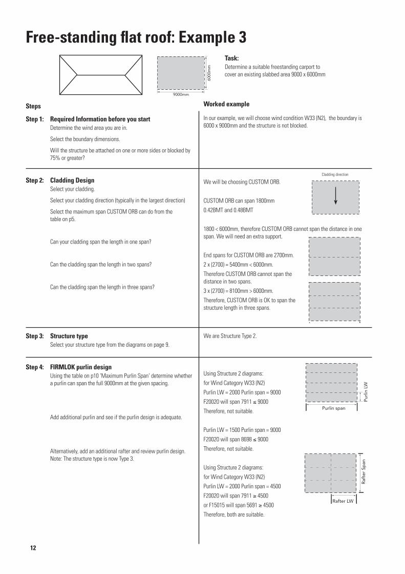
In our example, we will choose wind condition W33 (N2), the boundary is 6000 x 9000mm and the structure is not blocked.
We will be choosing CUSTOM ORB.
CUSTOM ORB can span 1800mm
0.42BMT and 0.48BMT
1800 < 6000mm, therefore CUSTOM ORB cannot span the distance in one span. We will need an extra support.
End spans for CUSTOM ORB are 2700mm.
2 x (2700) = 5400mm < 6000mm.
Therefore CUSTOM ORB cannot span the distance in two spans.
3 x (2700) = 8100mm > 6000mm.
Therefore, CUSTOM ORB is OK to span thestructure length in three spans.
We are Structure Type 2.
Using Structure 2 diagrams:
for Wind Category W33 (N2)
Purlin LW = 2000 Purlin span = 9000
F20020 will span 7911 9000
Therefore, not suitable.
Purlin LW = 1500 Purlin span = 9000
F20020 will span 8698 9000
Therefore, not suitable.
Using Structure 2 diagrams:
for Wind Category W33 (N2)
Purlin LW = 2000 Purlin span = 4500
F20020 will span 7911 4500
or F15015 will span 5691 4500
Therefore, both are suitable.
Determine a suitable freestanding carport to cover an existing slabbed area 9000 x 6000mm
Steps
6000
mm
9000mm
Pur
linLW
Purlin span
Raf
ter
Span
Rafter LW
Determine the wind area you are in.
Select the boundary dimensions.
Will the structure be attached on one or more sides or blocked by 75% or greater?
Select your cladding.
Select your cladding direction (typically in the largest direction)
Select the maximum span CUSTOM ORB can do from the table on p5.
Can your cladding span the length in one span?
Can the cladding span the length in two spans?
Can the cladding span the length in three spans?
Select your structure type from the diagrams on page 9.
FIRMLOK purlin design Using the table on p10 ‘Maximum Purlin Span‘ determine whether
a purlin can span the full 9000mm at the given spacing.
Add additional purlin and see if the purlin design is adequate.
Alternatively, add an additional rafter and review purlin design. Note: The structure type is now Type 3.
Cladding direction

For Wind Category W33 (N2),
Rafter LW = 4500
Rafter Span = 6000mm
Number of intermediate purlins = 2
From the table for F20020 -
Simple span = 6226 6000 , therefore, it will do the span.
For Wind Category W33 (N2),
Beam Rafter LW = 3000
Beam Rafter Span = 9000mm
Number of intermediate purlins = 1
From the table for F20020 -
Simple span = 6646 < 9000 , therefore, it will not do the span.
For Wind Category W33 (N2),
Beam Rafter Span is reduced to
4500mm, therefore OK.
In this case connections 3, 4 or 5 are applicable. See below.
Bea
m R
afte
r LW
Beam Rafter Span
BeamRafter Span
Bea
m R
afte
r LW
Using the table Maximum Rafter Span on p10 (simple spans) determine whether the rafter can span the full length.
Using the table Maximum Rafter Span on p10 (simple spans) using Beam Rafter load widths instead of beam load Widths determine whether the rafter can span the full length.
Add post to support beam rafter and review Beam Rafter design.
For your structure type, the diagrams on page 9 indicate which connections you can have.
Purlin4
3
5
Raft
er
Sp
an P
urlin
LW
=Rafter
LW
Bea
m R
afte
rLW
Beam Rafter Span
Raf
ter
Span
Rafter LW

Gable roofs
1010 6
7 7
6
With collar tie
Gable spacingGable spacing
GableWidth
GableWidth
9
7Gable spacing
GableWidth
GableWidth
8
6
9 7Gable spacingMight requiredouble rafters
θ
Gable width
Gable pitch
θ
Gable width
Gable pitch Rafter length
6
Intermediate purlins where applicable
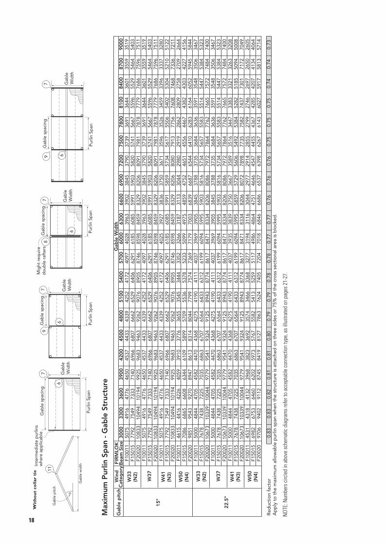
When checking cladding span, rafter length mustbe calculated using the following formula:For a 15º gable pitch, Rafter length = 0.52 x gable widthFor a 22.5º gable pitch, Rafter length = 0.54 x gable widthNote: These equations are estimations for choosing the cladding only, not precise dimensions for construction.
Numbers circled in above schematic diagrams refer to acceptable connection type, as illustrated on pages 21-27.
Collar ties must be placed on all gable rafters. Collar ties must always be positioned in accordance with Connection 10. (p26)
Gable width goes to backside of bracket.

Max
imum
Pur
lin S
pan
- G
able
Str
uctu
re w
ith
Co
llar
Tie
30
00
33
00
36
00
39
00
42
00
45
00
48
00
51
00
54
00
57
00
60
00
63
00
66
00
69
00
72
00
75
00
78
00
F100
1150
7549
1647
7646
5045
3744
3343
3942
5241
7240
9740
2839
6339
0238
4537
9037
3936
91F1
5015
7792
7549
7333
7140
6966
6807
6662
6529
6406
6291
6185
6085
5991
5903
5820
5741
5667
F200
2010
833
1049
410
194
9925
9683
9463
9262
9076
8905
8746
8598
8459
8329
8206
8091
7981
7878
F100
1150
7549
1647
7646
5045
3744
3343
3942
5241
7240
9740
2839
6339
0238
4537
9037
3936
91F1
5015
7792
7549
7333
7140
6966
6807
6662
6529
6406
6291
6185
6085
5991
5903
5820
5741
5667
15
ºF2
0020
1083
310
494
1019
499
2596
8394
6392
6290
7689
0587
4685
9884
5983
2982
0680
9179
8178
78F1
0011
5075
4916
4776
4650
4537
4433
4339
4252
4172
4097
4025
3927
3836
3750
3671
3596
3526
F150
1577
9275
4973
3371
4069
6668
0766
6265
2964
0662
9161
8560
8559
9158
5957
3456
1755
06F2
0020
1083
310
494
1019
499
2596
8394
6392
6290
7689
0587
4685
9884
5983
2982
0680
8079
1377
56F1
0011
4615
4416
4226
4059
3910
3776
3655
3545
3444
3352
3266
3187
3113
3044
2980
2919
2862
F150
1570
8668
6566
0863
4461
0958
9957
0955
3653
7852
3350
9949
7548
5947
5246
5145
5644
67F2
0020
9851
9543
9270
8947
8613
8314
8044
7799
7574
7369
7179
7003
6839
6687
6544
6410
6283
F100
1150
0048
4447
0545
8244
7043
6842
7541
9041
1140
3739
6939
0538
4537
8837
3536
8436
36F1
5015
7678
7438
7225
7035
6863
6707
6564
6433
6312
6199
6094
5995
5903
5816
5734
5657
5583
F200
2010
673
1033
910
044
9779
9541
9324
9125
8943
8774
8617
8471
8334
8206
8086
7972
7864
7762
F100
1150
0048
4447
0545
8244
7043
6842
7541
9041
1140
3739
6939
0538
4537
8837
3536
8436
36F1
5015
7678
7438
7225
7035
6863
6707
6564
6433
6312
6199
6094
5995
5903
5816
5734
5657
5583
22
.5 º
F200
2010
673
1033
910
044
9779
9541
9324
9125
8943
8774
8617
8471
8334
8206
8086
7972
7864
7762
F100
1150
0048
4447
0545
8244
7043
6842
7541
9041
1140
3739
3538
3937
5036
6735
8935
1634
47F1
5015
7678
7438
7225
7035
6863
6707
6564
6433
6312
6199
6094
5995
5859
5729
5606
5492
5384
F200
2010
673
1033
910
044
9779
9541
9324
9125
8943
8774
8617
8471
8334
8206
8072
7898
7735
7582
F100
1145
3143
1841
3239
6838
2336
9235
7434
6633
6832
7731
9431
1630
4429
7729
1428
5527
99F1
5015
6982
6753
6460
6202
5973
5767
5582
5413
5259
5117
4986
4864
4751
4646
4547
4455
4367
F200
2097
0694
0291
1287
4584
1981
2778
6376
2474
0572
0470
1868
4666
8665
3763
9862
6761
43
Red
ucti
on
fact
or
0.83
0.83
0.82
0.81
0.81
0.80
0.79
0.79
0.78
0.78
0.77
0.77
0.76
0.76
0.76
0.75
0.75
Win
dC
ateg
ory
FIR
MLO
KB
eam
Siz
e
W5
0(N
4)
W3
7
Gab
le p
itch
Gab
le W
idth
W3
3(N
2)
W3
7
W4
1(N
3)
81
00
84
00
87
00
90
00
3644
3601
3559
3519
5596
5529
5464
5403
7779
7686
7596
7511
3644
3601
3559
3519
5596
5529
5464
5403
7779
7686
7596
7511
3459
3396
3337
3280
5402
5304
5210
5122
7608
7468
7336
7211
2809
2758
2709
2664
4382
4303
4227
4156
6164
6052
5945
5844
3591
3548
3506
3467
5514
5447
5384
5323
7665
7572
7484
7400
3591
3548
3506
3467
5514
5447
5384
5323
7665
7572
7484
7400
3383
3321
3263
3208
5282
5185
5094
5008
7437
7301
7172
7049
2746
2697
2650
2605
4285
4207
4134
4064
6027
5917
5813
5714
0.75
0.74
0.74
0.73
Ap
ply
to
max
imum
pur
lin s
pan
whe
n st
ruct
ure
is a
ttac
hed
on
thre
e si
des
or
75%
of
cro
ss s
ecti
ona
l are
a is
blo
cked
.
1010
6
77
6
Wit
h c
olla
r ti
e
Pur
lin S
pan
Pur
linSp
an
Gab
le s
pac
ing
Gab
le s
pac
ing
Gab
leW
idth
Gab
leW
idth
97
Pur
lin S
pan
Pur
lin S
pan
Gab
le s
pac
ing
Gab
leW
idth
Gab
leW
idth
8
697
Gab
le s
pac
ing
Mig
ht r
equi
red
oub
le r
afte
rs
θ
Gab
le w
idth
Gab
le p
itch
6
Inte
rmed
iate
pur
lins
whe
re a
pp
licab
le
W5
0(N
4)
W3
3(N
2)
W4
1(N
3)
NOTE
:Num
bers
circ
led
in a
bove
sche
mat
ic di
agra
ms r
efer
to a
ccep
tabl
e co
nnec
tion
type
, as i
llust
rate
d on
pag
es 2
1-27
.

01
01
01
01
01
01
01
01
01
01
01
01
01
01
01
01
F100
1146
5443
0843
2040
1240
5537
7738
4135
8636
5934
2535
0432
8633
7131
6632
5330
6231
4929
6730
5428
8229
6928
0528
9227
3628
2126
7227
5726
1426
9525
5826
3925
08F1
5015
7874
7115
7308
6626
6862
6240
6497
5923
6192
5656
5931
5430
5705
5231
5506
5058
5328
4901
5146
4762
4837
4635
4567
4521
4327
4414
4115
4206
3924
4011
3752
3833
F200
2010
289
1046
397
7197
4493
5291
7490
0687
0985
6283
1977
6079
4471
0572
7165
5967
0960
9562
3656
9758
2853
5154
7550
5051
6447
8348
9145
4646
4643
3144
2841
4042
33F1
0011
4256
3956
3951
3684
3709
3470
3512
3294
3346
3145
3205
3018
3083
2907
2975
2811
2878
2724
2793
2647
2716
2577
2645
2513
2581
2453
2521
2399
2465
2349
2370
2303
F150
1572
0265
3466
8460
8562
7757
3059
4254
4056
6251
9554
2549
8651
9948
0548
0846
4444
7845
0141
9242
8739
4740
3437
2838
1235
3736
1433
6734
4132
1532
8430
7631
43F2
0020
9640
9607
9155
8948
8736
8427
7714
7894
6916
7078
6279
6423
5757
5888
5320
5442
4951
5061
4633
4737
4358
4455
4117
4208
3902
3989
3713
3794
3541
3618
3388
3462
F100
1139
2736
6336
4534
1234
2132
1332
4030
5030
8729
1329
5827
9528
4426
9327
4526
0426
5625
2325
7724
5224
8823
8623
5923
2622
4522
7221
4221
8520
5020
9219
6720
07F1
5015
6646
6051
6166
5635
5790
5307
5483
5038
5067
4810
4611
4617
4238
4331
3926
4012
3661
3740
3433
3506
3234
3303
3060
3126
2907
2969
2770
2828
2647
2703
2537
2589
F200
2090
3388
9881
4582
8670
6172
2562
4663
8956
1057
3851
0052
1646
8347
8943
3544
3240
4041
2837
8438
6835
6436
4233
7134
4431
9932
6930
4731
1229
1129
7327
8828
46F1
0011
3340
3139
3101
2923
2911
2753
2757
2614
2627
2496
2452
2395
2266
2309
2112
2154
1980
2019
1866
1903
1766
1800
1679
1712
1602
1632
1532
1561
1470
1497
1412
1439
F150
1556
5351
8549
8848
3043
4944
4538
6639
5134
8935
6431
8632
5529
3830
0027
3027
8825
5426
0624
0124
5222
6823
1621
5221
9720
5020
9019
5719
9618
7419
1317
9918
35F2
0020
6520
6671
5521
5647
4806
4915
4267
4364
3848
3933
3510
3587
3234
3303
3002
3066
2805
2865
2637
2691
2488
2540
2359
2409
2245
2291
2142
2187
2052
2092
1969
2007
F100
1146
5343
0743
2040
1140
5637
7938
4035
8736
5934
2635
0532
8733
7031
6732
5430
6231
4929
6830
5428
8329
6928
0728
9227
3728
2226
7227
5726
1326
9625
5926
4025
07F1
5015
7875
7116
7308
6626
6863
6240
6499
5924
6192
5658
5931
5429
5704
5231
5504
5057
5327
4902
5168
4762
5024
4636
4895
4520
4775
4414
4664
4316
4562
4228
4468
4143
F200
2010
092
1046
295
8497
4391
7491
7688
3487
1085
4483
1982
9379
8480
7176
9278
7574
3577
0072
0675
3570
0173
8268
1572
4066
4671
0664
9168
1663
4764
8662
1661
8660
92F1
0011
4255
3956
3951
3684
3708
3470
3513
3293
3346
3145
3206
3019
3082
2908
2975
2810
2879
2725
2794
2648
2716
2578
2644
2513
2579
2454
2520
2400
2465
2350
2415
2302
F150
1572
0365
3466
8560
8762
7757
3059
4254
4056
6351
9654
2549
8552
1648
0450
3546
4348
7345
0147
2743
7245
9542
5744
7541
5043
6640
5442
6539
6341
7238
8240
8538
05F2
0020
9455
9608
8980
8949
8596
8426
8276
7999
8006
7639
7770
7332
7559
7064
7367
6827
7191
6619
6953
6430
6524
6258
6149
6103
5817
5961
5521
5826
5257
5545
5020
5294
F100
1139
2636
6436
4434
1134
2232
1332
4130
4930
8829
1229
5827
9628
4426
9427
4626
0326
5725
2425
7824
5225
0623
8524
4123
2623
8022
7323
2622
2322
7521
7722
2721
32F1
5015
6645
6051
6168
5636
5791
5307
5482
5037
5225
4812
5006
4618
4813
4449
4645
4300
4496
4169
4361
4048
4241
3941
4124
3843
3910
3755
3718
3671
3546
3594
3392
3524
F200
2088
6288
9784
1582
8780
5678
0377
5774
0874
9670
7572
6467
8970
3165
4164
8963
2360
2961
2956
3459
4652
9255
8249
9352
6447
2849
8544
9247
3442
8145
1040
9143
09F1
0011
3341
3139
3101
2923
2910
2753
2757
2613
2626
2496
2515
2395
2419
2308
2336
2230
2260
2162
2191
2101
2130
2045
2040
1994
1942
1948
1855
1905
1778
1863
1705
1787
F150
1556
5251
8552
4648
3049
2645
4746
6443
1644
4441
2242
5739
5639
5238
1236
6236
8434
1535
5332
0433
7030
1931
7428
5730
0427
1428
5325
8727
1824
7225
9823
6924
89F2
0020
7862
7626
7459
7101
7118
6687
6386
6347
5734
6050
5209
5495
4780
5041
4424
4662
4119
4340
3858
4063
3633
3825
3433
3614
3258
3428
3102
3263
2962
3113
2834
2980
Red
ucti
on
fact
or
0.68
0.70
0.65
0.67
0.63
0.65
0.61
0.64
0.60
0.62
0.59
0.61
0.58
0.60
0.58
0.59
0.57
0.59
0.57
0.58
0.56
0.58
0.56
0.57
0.56
0.57
0.56
0.57
0.56
0.57
0.56
0.57
No
.inte
rmed
iate
pur
lins
3900
Gab
leP
itch
15º
22.5
º
W37
W37
4800
Win
dC
ateg
ory
FIR
MLO
KB
eam
Gab
le L
oad
Wid
th1500
1800
2100
2400
2700
6000
5100
3000
3300
4200
4500
5400
5700
3600
Max
imum
Gab
le W
idth
- G
able
wit
h co
llar
tie
1010
6
77
6
Wit
h c
olla
r ti
e
Gab
leLW
Gab
leLW
Gab
leLW
Gab
leLW
Gab
le s
pac
ing
Gab
le s
pac
ing
Gab
leW
idth
Gab
leW
idth
97
Gab
le s
pac
ing
Gab
leW
idth
Gab
leW
idth
8
697
Gab
le s
pac
ing
Mig
ht r
equi
red
oub
le r
afte
rs
θ
Gab
le w
idth
Gab
le p
itch
6
Inte
rmed
iate
pur
lins
whe
re a
pp
licab
le
Ap
ply
to
the
max
imum
allo
wab
le g
able
wid
th w
hen
the
stru
ctur
e is
att
ache
d o
n th
ree
sid
es o
r 75
% o
f th
e cr
oss
sec
tio
nal a
rea
is b
lock
ed.
W50
(N4)
W33
(N2)
W41
(N3)
W50
(N4)
W33
(N2)
W41
(N3)
NOTE
:Num
bers
circ
led
in a
bove
sche
mat
ic di
agra
ms r
efer
to a
ccep
tabl
e co
nnec
tion
type
, as i
llust
rate
d on
pag
es 2
1-27
.

11
6
7 7
6
Without collar tie
Gable spacingGable spacing
GableWidth
GableWidth
9
7Gable spacing
GableWidth
GableWidth
8
6
9 7Gable spacingMight requiredouble rafters
θ
Gable width
Gable pitch
6
Intermediate purlins where applicable
θ
Gable width
Gable pitch Rafter length
When checking cladding span, rafter length mustbe calculated using the following formula:For a 15º gable pitch, Rafter length = 0.52 x gable widthFor a 22.5º gable pitch, Rafter length = 0.54 x gable widthNote: These equations are estimations for choosing the cladding only, not precise dimensions for construction.
NOTE: Numbers circled in above schematic diagrams refer to acceptable connection type, as illustrated on pages 21-27.
Gable width goes to backside of bracket.
Gable roofs
NOTE
:Num
bers
circ
led
in a
bove
sche
mat
ic di
agra
ms r
efer
to a
ccep
tabl
e co
nnec
tion
type
, as i
llust
rate
d on
pag
es 2
1-27
.
Max
imum
Pur
lin S
pan
- G
able
Str
uctu
re
30
00
33
00
36
00
39
00
42
00
45
00
48
00
51
00
54
00
57
00
60
00
63
00
66
00
69
00
72
00
75
00
78
00
F100
1150
7549
1647
7646
5045
3744
3343
3942
5241
7240
9740
2839
6339
0238
4537
9037
3936
91F1
5015
7792
7549
7333
7140
6966
6807
6662
6529
6406
6291
6185
6085
5991
5903
5820
5741
5667
F200
2010
833
1049
410
194
9925
9683
9463
9262
9076
8905
8746
8598
8459
8329
8206
8091
7981
7878
F100
1150
7549
1647
7646
5045
3744
3343
3942
5241
7240
9740
2839
6339
0238
4537
9037
3936
91F1
5015
7792
7549
7333
7140
6966
6807
6662
6529
6406
6291
6185
6085
5991
5903
5820
5741
5667
15
ºF2
0020
1083
310
494
1019
499
2596
8394
6392
6290
7689
0587
4685
9884
5983
2982
0680
9179
8178
78F1
0011
5075
4916
4776
4650
4537
4433
4339
4252
4172
4097
4025
3927
3836
3750
3671
3596
3526
F150
1577
9275
4973
3371
4069
6668
0766
6265
2964
0662
9161
8560
8559
9158
5957
3456
1755
06F2
0020
1083
310
494
1019
499
2596
8394
6392
6290
7689
0587
4685
9884
5983
2982
0680
8079
1377
56F1
0011
4615
4416
4226
4059
3910
3776
3655
3545
3444
3352
3266
3187
3113
3044
2980
2919
2862
F150
1570
8668
6566
0863
4461
0958
9957
0955
3653
7852
3350
9949
7548
5947
5246
5145
5644
67F2
0020
9851
9543
9270
8947
8613
8314
8044
7799
7574
7369
7179
7003
6839
6687
6544
6410
6283
F100
1150
0048
4447
0545
8244
7043
6842
7541
9041
1140
3739
6939
0538
4537
8837
3536
8436
36F1
5015
7678
7438
7225
7035
6863
6707
6564
6433
6312
6199
6094
5995
5903
5816
5734
5657
5583
F200
2010
673
1033
910
044
9779
9541
9324
9125
8943
8774
8617
8471
8334
8206
8086
7972
7864
7762
F100
1150
0048
4447
0545
8244
7043
6842
7541
9041
1140
3739
6939
0538
4537
8837
3536
8436
36F1
5015
7678
7438
7225
7035
6863
6707
6564
6433
6312
6199
6094
5995
5903
5816
5734
5657
5583
22
.5º
F200
2010
673
1033
910
044
9779
9541
9324
9125
8943
8774
8617
8471
8334
8206
8086
7972
7864
7762
F100
1150
0048
4447
0545
8244
7043
6842
7541
9041
1140
3739
3538
3937
5036
6735
8935
1634
47F1
5015
7678
7438
7225
7035
6863
6707
6564
6433
6312
6199
6094
5995
5859
5729
5606
5492
5384
F200
2010
673
1033
910
044
9779
9541
9324
9125
8943
8774
8617
8471
8334
8206
8072
7898
7735
7582
F100
1145
3143
1841
3239
6838
2336
9235
7434
6633
6832
7731
9431
1630
4429
7729
1428
5527
99F1
5015
6982
6753
6460
6202
5973
5767
5582
5413
5259
5117
4986
4864
4751
4646
4547
4455
4367
F200
2097
0694
0291
1287
4584
1981
2778
6376
2474
0572
0470
1868
4666
8665
3763
9862
6761
43
Red
ucti
on
fact
or
0.83
0.83
0.82
0.81
0.81
0.80
0.79
0.79
0.78
0.78
0.77
0.77
0.76
0.76
0.76
0.75
0.75
Ap
ply
to
the
max
imum
allo
wab
le p
urlin
sp
an w
hen
the
stru
ctur
e is
att
ache
d o
n th
ree
sid
es o
r 75
% o
f th
e cr
oss
sec
tio
nal a
rea
is b
lock
ed.
Win
dC
ateg
ory
FIR
MLO
KB
eam
Siz
e
W3
7
Gab
le p
itch
Gab
le W
idth
W3
7
81
00
84
00
87
00
90
00
3644
3601
3559
3519
5596
5529
5464
5403
7779
7686
7596
7511
3644
3601
3559
3519
5596
5529
5464
5403
7779
7686
7596
7511
3459
3396
3337
3280
5402
5304
5210
5122
7608
7468
7336
7211
2809
2758
2709
2664
4382
4303
4227
4156
6164
6052
5945
5844
3591
3548
3506
3467
5514
5447
5384
5323
7665
7572
7484
7400
3591
3548
3506
3467
5514
5447
5384
5323
7665
7572
7484
7400
3383
3321
3263
3208
5282
5185
5094
5008
7437
7301
7172
7049
2746
2697
2650
2605
4285
4207
4134
4064
6027
5917
5813
5714
0.75
0.74
0.74
0.73
11
6
77
6
Wit
ho
ut
colla
r ti
e
Pur
lin S
pan
Pur
lin S
pan
Gab
le s
pac
ing
Gab
le s
pac
ing
Gab
leW
idth
Gab
leW
idth
97
Pur
lin S
pan
Pur
lin S
pan
Gab
le s
pac
ing
Gab
leW
idth
Gab
leW
idth
8
697
Gab
le s
pac
ing
Mig
ht r
equi
red
oub
le r
afte
rs
θ
Gab
le w
idth
Gab
le p
itch
6
Inte
rmed
iate
pur
lins
whe
re a
pp
licab
le
W5
0(N
4)
W3
3(N
2)
W4
1(N
3)
W5
0(N
4)
W3
3(N
2)
W4
1(N
3)

NOTE
:Num
bers
circ
led
in a
bove
sche
mat
ic di
agra
ms r
efer
to a
ccep
tabl
e co
nnec
tion
type
, as i
llust
rate
d on
pag
es 2
1-27
.
01
01
01
01
01
01
01
01
01
01
01
01
01
01
01
01
F100
1144
8245
6540
9241
6737
8838
5835
4336
0933
4034
0231
6832
2630
2130
7728
9229
4627
8028
3026
7827
2825
8726
3525
0625
5224
3024
7523
6124
0522
9923
4122
4122
82F1
5015
6721
6845
6136
6248
5680
5784
5313
5411
5009
5102
4752
4839
4530
4615
4337
4418
4167
4244
4016
4090
3879
3951
3757
3825
3643
3711
3541
3607
3446
3510
3359
3421
F200
2079
6991
2275
6783
2872
4377
1069
7472
1266
7668
0063
3564
5060
3961
5157
8258
8855
5456
5653
5354
5251
7252
6650
0751
0048
5749
4747
2148
0845
9446
7944
7845
61F1
0011
3995
4068
3647
3715
3377
3439
3159
3217
2977
3033
2824
2877
2693
2743
2579
2625
2477
2523
2388
2430
2307
2349
2233
2274
2166
2206
2106
2144
2050
2086
1998
2034
F150
1559
9161
0154
6955
7050
6351
5647
3748
2444
6545
4842
3743
1440
4041
1338
6839
3937
1537
8435
8036
4534
5835
2233
4834
1032
4933
0931
5732
1530
7431
3029
9430
50F2
0020
7467
8133
7090
7424
6748
6874
6313
6429
5952
6062
5647
5751
5384
5483
5154
5249
4951
5044
4772
4861
4609
4694
4463
4546
4329
4410
4208
4285
4096
4171
3991
4067
F100
1135
6236
2832
5133
1130
1030
6628
1728
6926
5427
0525
1925
6524
0124
4622
9923
4122
0822
5121
2921
6820
5520
9419
9220
2819
3219
6718
7819
1318
2818
6017
8118
14F1
5015
5342
5440
4876
4967
4515
4598
4223
4302
3982
4055
3777
3846
3601
3669
3448
3512
3313
3375
3191
3251
3083
3141
2987
3041
2898
2950
2815
2867
2739
2792
2670
2720
F200
2069
9572
5265
0166
2060
1861
3056
2957
3453
0754
0550
3451
2748
0148
9045
9646
8144
1644
9742
5643
3341
1141
8639
8040
5338
6239
3337
5238
2136
5337
1935
6036
26F1
0011
2884
2936
2631
2681
2436
2482
2280
2322
2148
2189
2038
2077
1943
1980
1860
1895
1787
1822
1723
1754
1663
1694
1611
1642
1563
1592
1518
1547
1478
1507
1441
1468
F150
1543
2344
0539
4740
2036
5537
2334
1734
8132
2232
8230
5831
1429
1529
6927
9228
4226
8127
3225
8326
3124
9625
4224
1724
6123
4523
8822
7823
2022
1822
5821
6222
02F2
0020
5763
5869
5260
5359
4870
4961
4555
4640
4296
4376
4074
4150
3885
3956
3721
3788
3574
3640
3444
3508
3327
3388
3222
3280
3126
3184
3037
3093
2956
3010
2 880
2934
F100
1144
8146
8840
9142
7937
8839
6235
4237
0533
4134
9431
6933
1530
2131
6028
9230
2527
7929
0726
7728
0125
8727
0525
0626
2024
3025
4123
6124
7022
9924
0422
3923
43F1
5015
6650
7029
6135
6417
5680
5941
5312
5556
5009
5238
4752
4970
4531
4740
4339
4536
4169
4359
4015
4200
3880
4058
3756
3928
3644
3812
3542
3705
3448
3605
3359
3514
F200
2078
1893
6874
2285
5171
0579
1868
4074
0666
1769
8363
3466
2460
3863
1657
8260
4855
5458
0953
5355
9951
7254
0850
0752
3748
5850
7947
2149
3745
9548
0644
7946
84F1
0011
3995
4178
3647
3814
3376
3531
3158
3304
2977
3113
2825
2955
2694
2816
2578
2696
2478
2591
2387
2496
2306
2411
2232
2336
2166
2265
2105
2203
2049
2143
1997
2088
F150
1559
9062
6654
6957
2150
6352
9647
3649
5444
6646
6942
3744
3140
3942
2438
6740
4537
1638
8635
7937
4434
5936
1833
4835
0232
4833
9831
5833
0230
7332
1329
9531
32F2
0020
7325
8352
6955
7624
6657
7058
6312
6602
5952
6225
5647
5905
5383
5630
5153
5390
4952
5179
4771
4991
4610
4821
4464
4667
4329
4529
4207
4401
4096
4283
3993
4176
F100
1135
6237
2532
5234
0230
1031
4928
1629
4526
5527
7725
1826
3524
0225
1122
9924
0422
1023
1021
2922
2720
5721
5119
9220
8219
3120
2018
7719
6418
2719
1117
8118
63F1
5015
5342
5588
4876
5100
4516
4723
4224
4418
3982
4165
3777
3951
3601
3768
3448
3607
3313
3465
3193
3339
3084
3226
2986
3123
2897
3030
2816
2945
2740
2866
2670
2794
F200
2068
6374
4665
0067
9860
1862
9356
3058
8753
0755
5150
3552
6648
0050
2045
9548
0644
1646
1842
5544
4941
1143
0039
8041
6338
6240
3937
5339
2536
5338
1935
6137
23F1
0011
2883
3016
2631
2753
2437
2548
2280
2384
2149
2247
2038
2132
1944
2033
1861
1946
1789
1870
1722
1802
1665
1741
1611
1685
1563
1635
1519
1589
1478
1547
1441
1508
F150
1543
2445
2339
4741
2836
5538
2134
1835
7532
2233
7030
5831
9829
1630
4927
9029
1926
8128
0525
8327
0124
9626
1124
1725
2823
4524
5222
7823
8422
1723
1921
6222
62F2
0020
5763
6027
5261
5503
4871
5094
4557
4765
4296
4492
4074
4263
3886
4063
3720
3891
3574
3738
3444
3601
3328
3479
3221
3368
3125
3269
3038
3176
2956
3091
2 881
3014
Red
ucti
on
fact
or
0.71
0.69
0.70
0.69
0.70
0.69
0.70
0.69
0.69
0.69
0.69
0.69
0.69
0.69
0.69
0.69
0.69
0.69
0.69
0.69
0.69
0.69
0.69
0.69
0.69
0.69
0.69
0.69
0.69
0.69
0.69
0.69
22
.5º
15
º
Gab
leP
itch
W3
7
54
00
57
00
36
00
39
00
No
. in
term
edia
te p
urlin
s
W3
7
48
00
Win
dC
ateg
ory
FIR
MLO
KB
eam
Size
Gab
le L
oad
Wid
th1
50
01
80
02
10
02
40
02
70
06
00
05
10
03
00
03
30
04
20
04
50
0
Max
imum
Gab
le W
idth
- G
able
wit
hout
co
llar
tie
11
6
77
6
Wit
ho
ut
colla
r ti
e
Gab
leLW
Gab
leLW
Gab
leLW
Gab
leLW
Gab
le s
pac
ing
Gab
le s
pac
ing
Gab
leW
idth
Gab
leW
idth
97
Gab
le s
pac
ing
Gab
leW
idth
Gab
leW
idth
8
697
Gab
le s
pac
ing
Mig
ht r
equi
red
oub
le r
afte
rs
θ
Gab
le w
idth
Gab
le p
itch
6
Inte
rmed
iate
pur
lins
whe
re a
pp
licab
le
Ap
ply
to
max
imum
gab
le w
idth
whe
n st
ruct
ure
is a
ttac
hed
on
thre
e si
des
or
75%
of
cro
ss s
ecti
ona
l are
a is
blo
cked
.
W5
0(N
4)
W3
3(N
2)
W4
1(N
3)
W5
0(N
4)
W3
3(N
2)
W4
1(N
3)

Determine a suitable gable structure to cover an internal paved area 5100 x 4800mm.
Determine the wind area you are in.
Select the boundary dimensions.
Will the structure be attached on one or more sides or blocked by 75% or greater?
Select your cladding.
Select your gable orientation (Gable width is typically in the shortest direction)
Select your roof pitch.
Select the maximum span SPANDEK can do from the table on page 5.
Can your cladding span the length in one span?
Select whether you want your gable with or without a collar tie.
FIRMLOK purlin design Using the table on page 15 ‘Allowable purlin span‘ gable structure,
determine whether a purlin can span the full 5100mm at the given spacing.
Using the table Allowable Gable Width on p16 (Gable with collar tie) determine whether a gable at each end is satisfactory.
For this structure type, the diagrams on page 11 indicate which connections you can have.
Steps
In our example, we will choose wind condition W33 (N2), the boundary is 5100 x 4800mm and the structure is attached on three sides. (i.e. blocked)
We will be choosing SPANDEK.
We will be choosing a 15° roof pitch.
SPANDEK can span 2700mm 0.42BMT
and 2950 0.48BMT
The rafter length for this gable is
2495mm, hence 0.42 or 0.48BMT will
do it in one span.
We have a collar tie.
For our structure, Purlin Span =
5100 Gable width = 4800mm
F15015 will span 6662 (0.79) =
5262 5100
Therefore, purlin can span the full length.
For our structure, Gable LW = 2550
Gable Width = 4800
Number of intermediate purlins = 0
From the table, for F15015 allowable
gable width is = 6344 x 0.61 =3838
< 4800 hence 15015 is not suitable.
For F20020 allowable gable width = 8784 x
0.61 =5314 > 4800 hence F20020 is suitable.
In this case connections 3 or 4 are
applicable. See below.
Gab
le W
idth
1010
q
Gable width
Rafter length = 2495
Purlin Span
Gab
le W
idth
Purlin Span
Gab
le W
idth
6
7
Gable LW
Gable spacing
GableWidth
Gable orientation
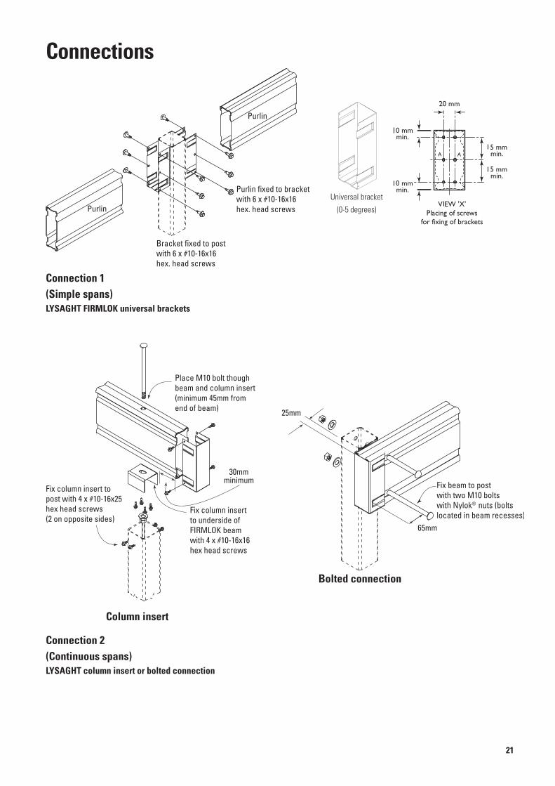
Connections
Connection 2(Continuous spans)LYSAGHT column insert or bolted connection
(Simple spans)LYSAGHT FIRMLOK universal brackets
Bracket fixed to post with 6 x #10-16x16hex. head screws
Purlin fixed to bracketwith 6 x #10-16x16hex. head screwsPurlin
Purlin
Fix column insertto underside of FIRMLOK beamwith 4 x #10-16x16 hex head screws
Fix column insert to post with 4 x #10-16x25 hex head screws(2 on opposite sides)
Place M10 bolt though beam and column insert(minimum 45mm from end of beam)
30mmminimum
Universal bracket
(0-5 degrees)
25mm
65mm
Fix beam to postwith two M10 boltswith Nylok® nuts (boltslocated in beam recesses)
Column insert
Bolted connection

22
Bracket fixed to rafter with 6 x #10-16x16hex. head screws
Purlin fixed to bracketwith 6 x #10-16x16hex. head screws
Bracket fixed to post with 6 x #10-16x16hex. head screws
Bracket fixed to FIRMLOKwith 6 x #10-16x16hex. head screws
Bracket fixed to FIRMLOKon outside face only with 2 x #10-16x16hex. head screws
Brackets joined withwith 6 x #10-16x16hex. head screws(not illustrated)
Fix rafter to post with two M10 bolts with Nylok® nuts
Fix purlin to post with one M10 bolt with Nylok® nut
Connection 3(Purlin to rafter or rafter to beam connection)
Connection 4(Typical bolted corner connection)
Connection 4(Typical screwed corner connection)

23
Bracket fixed to FIRMLOKon outside face only with 2 x #10-16x16hex. head screws
Brackets joined to rafterwith 6 x #10-16x16 hex. head screws(not illustrated)
Fix rafter to intermediate post with two M10 bolts with Nylok® nuts
Fix purlin to intermediate post with one M10 bolt with Nylok® nut
Connection 5(Intermediate post connection)
Connection 5(Screwed connection for continuous member)
Connection 5(Screwed connection for simple spanned member)
Bracket fixed to FIRMLOK with 4 x #10-16x16hex. head screws
Brackets connected to intermediate post with 6 x #10-16x16 hex. head screws (not illustrated)
Fix rafter to post with two M10 bolts with Nylok® nuts.Bolts will pass through universal bracket.
Bracket fixed to intermediate post with 6 x #10-16x16hex. head screws
Bracket fixed to FIRMLOKwith 6 x #10-16x16hex. head screws
Connection 5(Bolted connection for continuous member)
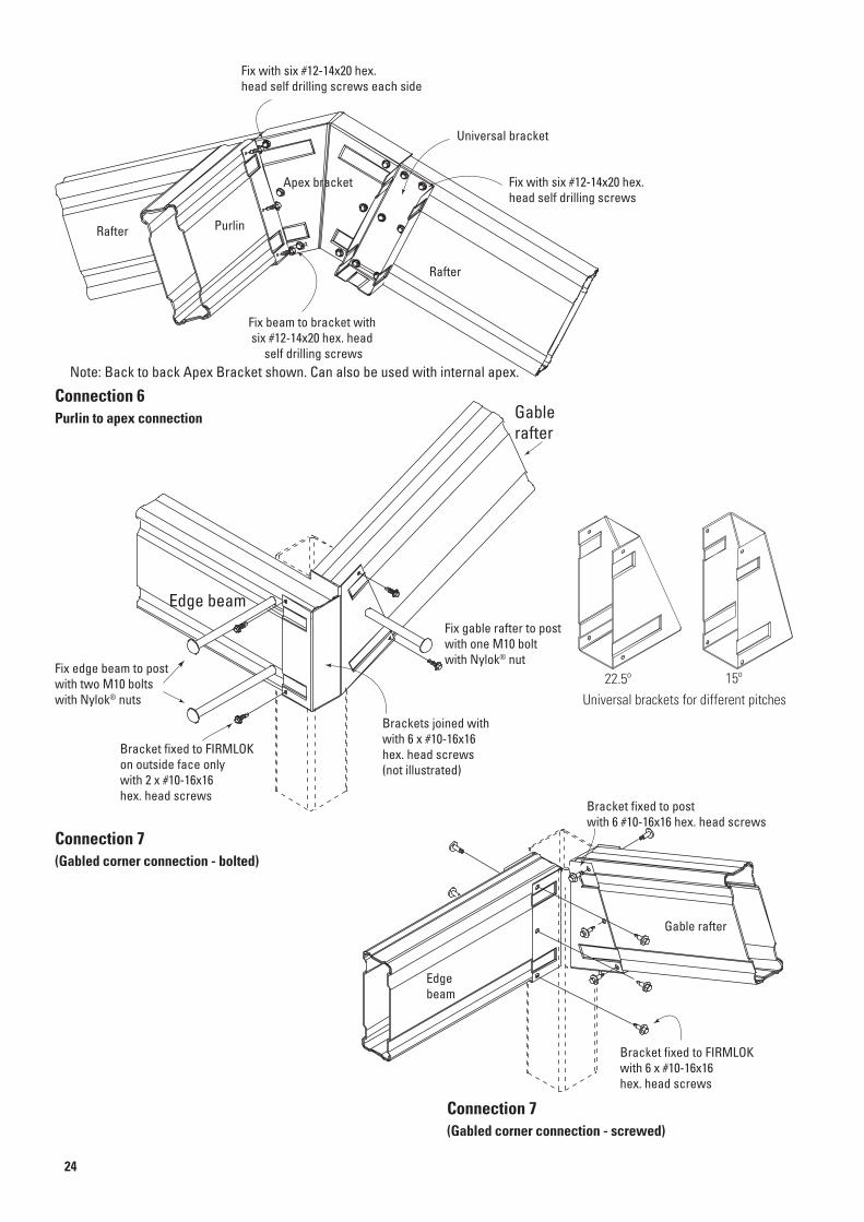
Bracket fixed to FIRMLOKon outside face only with 2 x #10-16x16hex. head screws
Brackets joined withwith 6 x #10-16x16hex. head screws(not illustrated)
Fix edge beam to post with two M10 bolts with Nylok® nuts
Fix gable rafter to post with one M10 bolt with Nylok® nut
Gablerafter
Edge beam
24
Connection 6Purlin to apex connection
Connection 7(Gabled corner connection - bolted)
Connection 7(Gabled corner connection - screwed)
Apex bracket
Universal bracket
Fix with six #12-14x20 hex. head self drilling screws each side
Fix with six #12-14x20 hex. head self drilling screws
Rafter
PurlinRafter
Fix beam to bracket with six #12-14x20 hex. head
self drilling screwsNote: Back to back Apex Bracket shown. Can also be used with internal apex.
Bracket fixed to post with 6 #10-16x16 hex. head screws
Bracket fixed to FIRMLOKwith 6 x #10-16x16hex. head screws
Edgebeam
Gable rafter
Universal brackets for different pitches22.5º 15º

25
Connection 8(Intermediate gable connection -twin rafter with post)
Connection 9(Bolted intermediate gable connection - with post)
Connection 9(Screwed intermediate gable connection - with post)
Bracket fixed to gable rafter on outside facewith 3 x #10-16x16hex. head screws
Brackets connected to rafter on top inside face with 1 x #10-16x16 hex. head screw
Fix edge beam to post with two M10 bolts with Nylok®
nuts.Fix gable rafter to intermediatepost with one M10 bolt with Nylok® nut.
Edge beam
Gablerafter
Gablerafter
Post
Bracket fixed to gablerafter on outside face only with 2 x #10-16x16hex. head screws
Brackets joined to edge beamwith 6 x #10-16x16 hex. head screws(not illustrated)
Fix rafter to intermediate post with two M10 bolts with Nylok® nuts
Fix gable rafter to intermediate post with one M10 bolt with Nylok® nut
Edge beam
Bracket fixed to gable rafter with 6 x #10-16x16hex. head screws
Brackets connected to intermediate post with 6 x #10-16x16 hex. head screws (not illustrated)
Fix edge beam to post with two M10 bolts with Nylok®
nuts. Bolts will pass through universal bracket.
Edge beam
Gablerafter

26
Gable with collar tie - Apex and collar tie connection
Collar tie & brackets
Gable Rafter
L
0.5L
0.3 L
VIEW 'X'Drill 2 holes 13mm dia.
for M12 bolts
50 mm
50 mm
X
X
2 off M12 x 30mmhex. head bolts andnuts with 3mm thicksquare washers underbolt heads and nuts
Rafters musttouch brackets here
12 x #10-16x16 screws(3 per rafter per side)
90º
Collar tie fixed to bracketwith 6 x #10-16x16hex. head screws
Collar tie fixed to gable rafter with 8 x #10-16x16 hex. head screws
Gable rafter
Collar tie bracket
Collar tie
Apex details
Typical gable rafter with collar tie
Collar tie details
==

27
Gable without collar tie - internal apex connection
LYSAGHT FIRMLOK apex brackets
For each bracket use:
classifications
On all 4 faces of bracket:For wind classificationsN1 (W28) use 5 screws
N2 (W33) & N3 (W41) use 6 screws
Place fasteners incentre at recess
Screws at 20mm centres
Apex bracket is availablefor pitches 15° and 22.5°
FIRMLOK must be mitred

Disclaimer, warranties and limitation of liabilityThis publication is intended to be an aid for all trades and professionals involved with specifying and installing LYSAGHT products and not to be a substitute for professional judgement.
Terms and conditions of sale available at local BlueScope Lysaght sales offices.
Except to the extent to which liability may not lawfully be excluded or limited, BlueScope Steel Limited will not be under or incur any liability to you for any direct or indirect loss or damage (including, without limitation, consequential loss or damage such as loss of profit or anticipated profit, loss of use, damage to goodwill and loss due to delay) however caused (including, without limitation, breach of contract, negligence and/or breach of statute), which you may suffer or incur in connection with this publication.
© Copyright BlueScope Steel Limited September 2010
Information, brochures and your local distributor
Please check the latest information which is always available atLYSAGHT, COLORBOND, TRIMDEK, CUSTOM ORB, FLATDEK, FIRMLOK AND ZINCALUME are registered trademarksof BlueScope Steel Limited, ABN 16 000 011 058. The LYSAGHT ® range of products is exclusively made by BlueScope Steel Limited trading as BlueScope Lysaght. Printed by BlueStar 1M0910


