F
M E T A L F A B R I C A T I N G M A C H I N E R Y
innovative technologies.
FIBERMAK Momentum Gen-3New Generation Fiber Laser
Innovative Technologies | www.ermaksan.com.tr | Laser Series
High Tech CNC machines manufactured by Ermaksan;
� New Generation Fiber Lasers
� CO2 Lasers
� Press Brakes
� Servo Motorized Hybrid Press Brakes
� Plasma Cutting Machines
� Punch Presses
� Shears
� Iron Workers
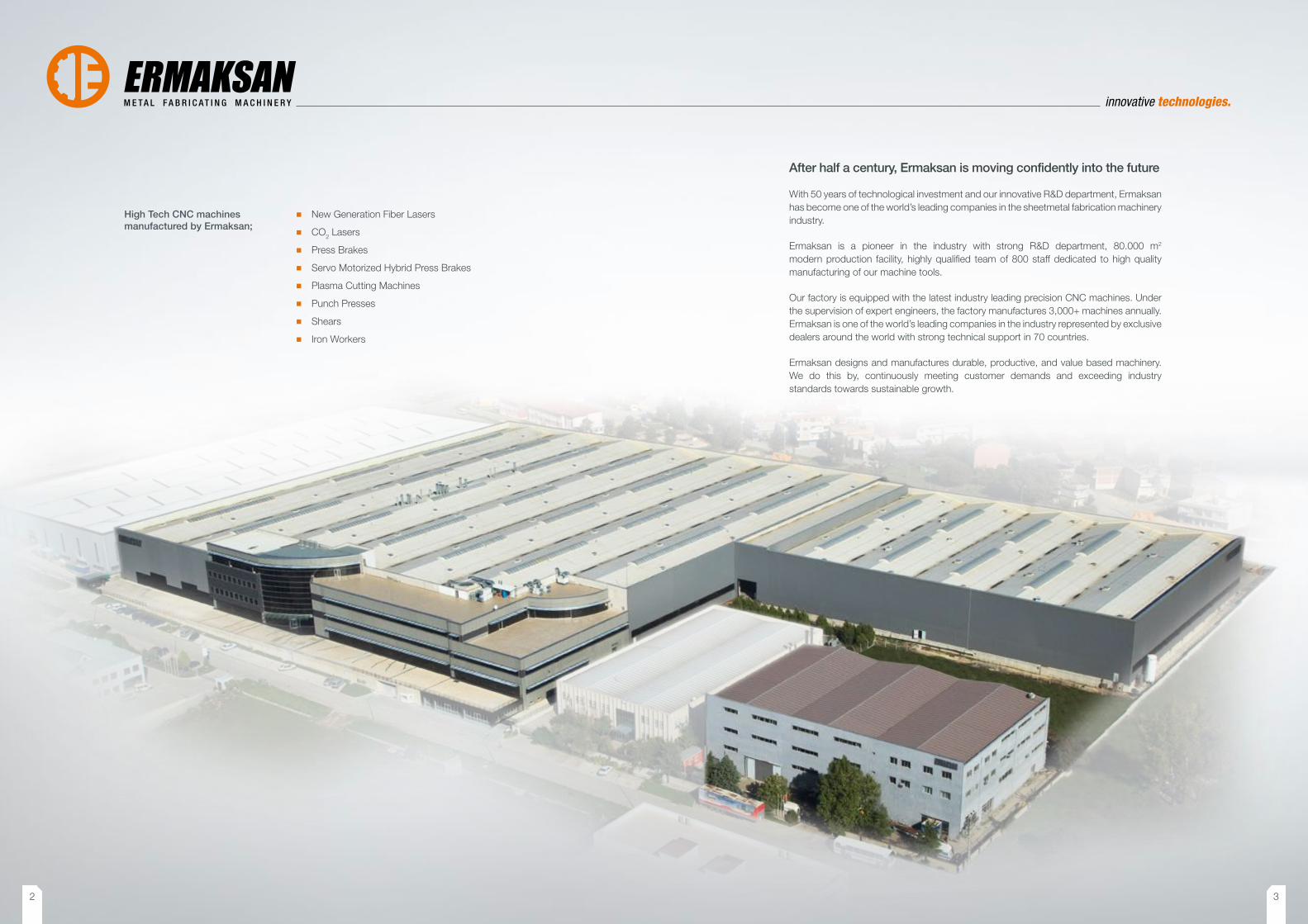
After half a century, Ermaksan is moving confidently into the future
With 50 years of technological investment and our innovative R&D department, Ermaksan has become one of the world’s leading companies in the sheetmetal fabrication machinery industry.
Ermaksan is a pioneer in the industry with strong R&D department, 80.000 m2 modern production facility, highly qualified team of 800 staff dedicated to high quality manufacturing of our machine tools.
Our factory is equipped with the latest industry leading precision CNC machines. Under the supervision of expert engineers, the factory manufactures 3,000+ machines annually. Ermaksan is one of the world’s leading companies in the industry represented by exclusive dealers around the world with strong technical support in 70 countries.
Ermaksan designs and manufactures durable, productive, and value based machinery. We do this by, continuously meeting customer demands and exceeding industry standards towards sustainable growth.
2 3
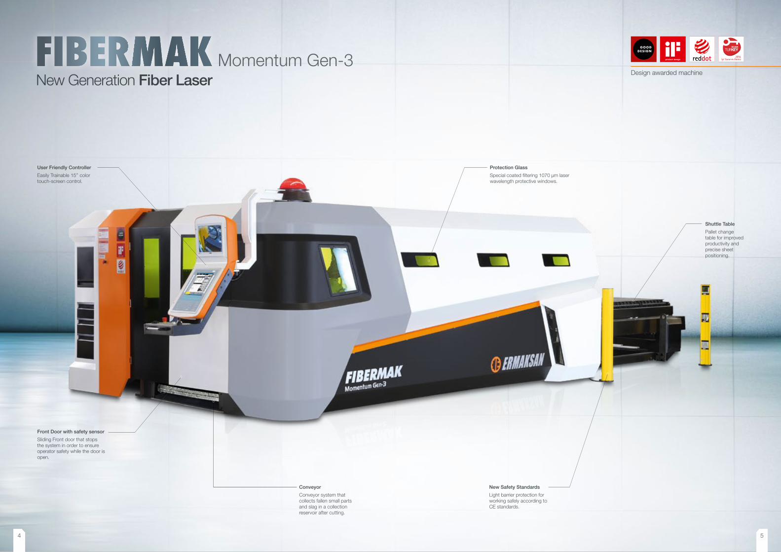
New Generation Fiber LaserMomentum Gen-3
Front Door with safety sensor
Sliding Front door that stops the system in order to ensure operator safety while the door is open.
Conveyor
Conveyor system that collects fallen small parts and slag in a collection reservoir after cutting.
Protection Glass
Special coated filtering 1070 μm laser wavelength protective windows.
New Safety Standards
Light barrier protection for working safely according to CE standards.
Shuttle Table
Pallet change table for improved productivity and precise sheet positioning.
User Friendly Controller
Easily Trainable 15’’ color touch-screen control.
Design awarded machine
4 5
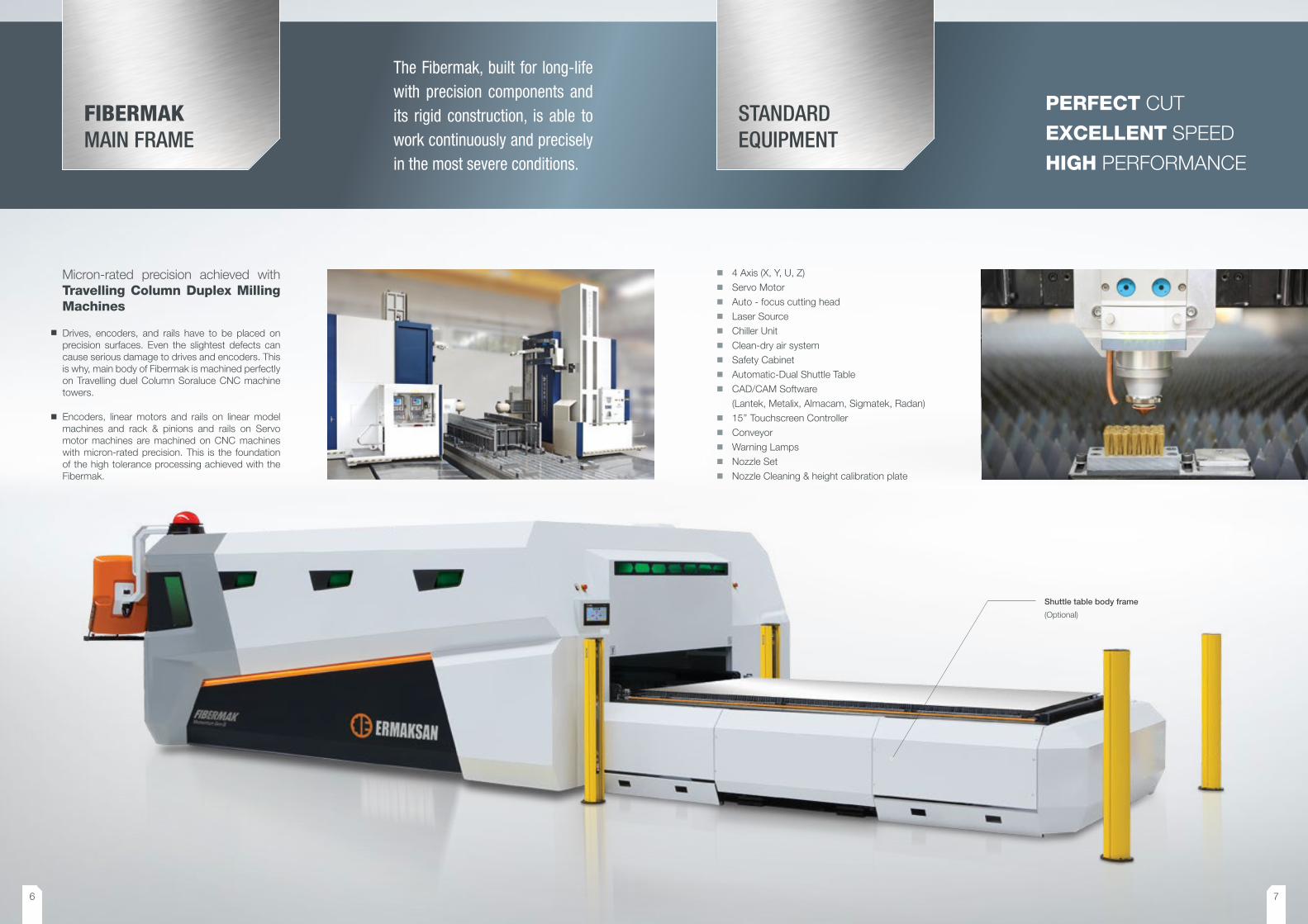
Micron-rated precision achieved withTravelling Column Duplex Milling Machines
FIBERMAKMAIN FRAME
The Fibermak, built for long-life with precision components and its rigid construction, is able to work continuously and precisely in the most severe conditions.
STANDARD EQUIPMENT
� 4 Axis (X, Y, U, Z) � Servo Motor � Auto - focus cutting head � Laser Source � Chiller Unit � Clean-dry air system � Safety Cabinet � Automatic-Dual Shuttle Table � CAD/CAM Software
(Lantek, Metalix, Almacam, Sigmatek, Radan) � 15’’ Touchscreen Controller � Conveyor � Warning Lamps � Nozzle Set � Nozzle Cleaning & height calibration plate
Shuttle table body frame
(Optional)
PERFECT CUT
EXCELLENT SPEED
HIGH PERFORMANCE
Drives, encoders, and rails have to be placed on precision surfaces. Even the slightest defects can cause serious damage to drives and encoders. This is why, main body of Fibermak is machined perfectly on Travelling duel Column Soraluce CNC machine towers.
Encoders, linear motors and rails on linear model machines and rack & pinions and rails on Servo motor machines are machined on CNC machines with micron-rated precision. This is the foundation of the high tolerance processing achieved with the Fibermak.
6 7
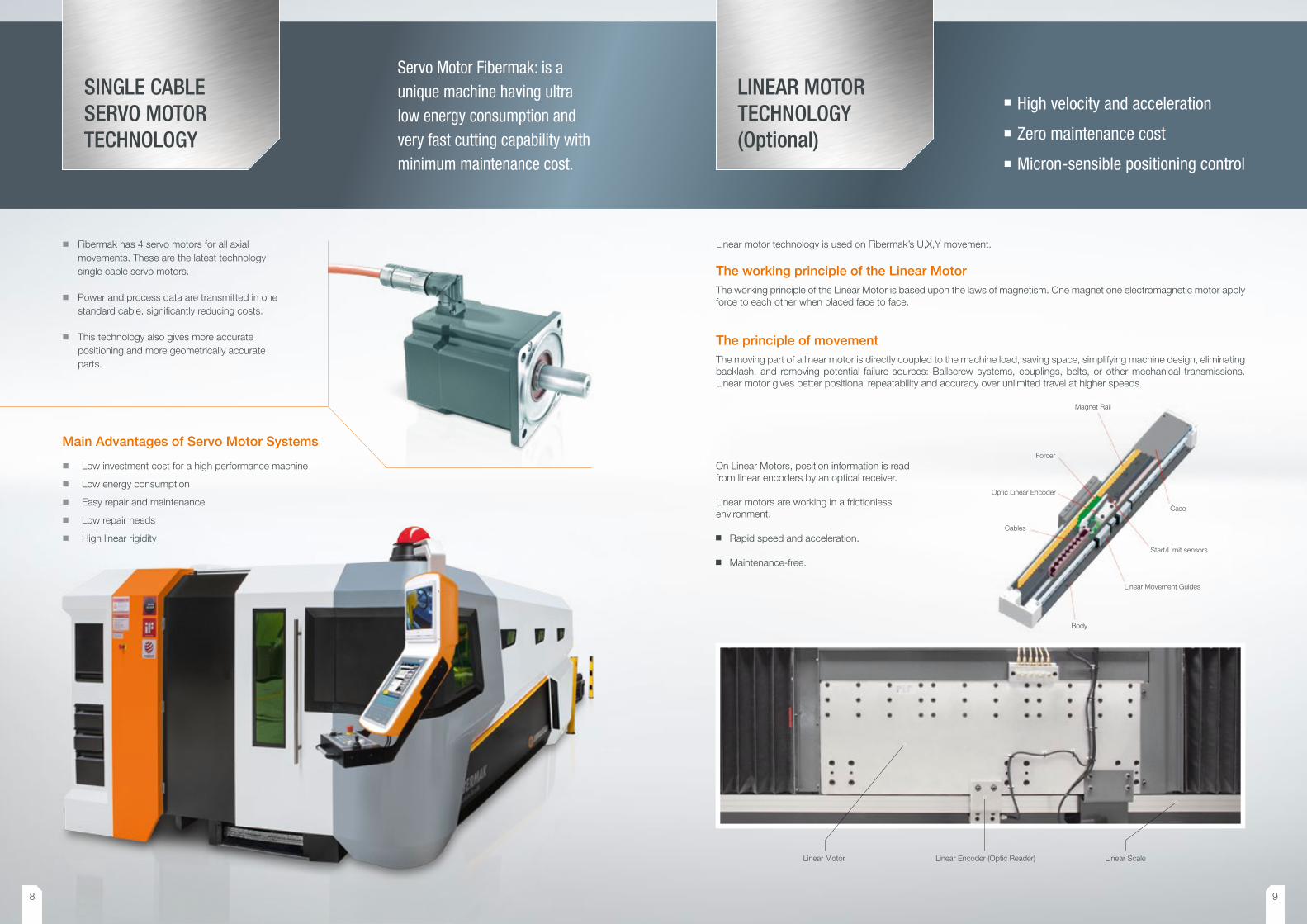
LINEAR MOTOR TECHNOLOGY(Optional)
Linear motor technology is used on Fibermak’s U,X,Y movement.
The working principle of the Linear MotorThe working principle of the Linear Motor is based upon the laws of magnetism. One magnet one electromagnetic motor apply force to each other when placed face to face.
The principle of movementThe moving part of a linear motor is directly coupled to the machine load, saving space, simplifying machine design, eliminating backlash, and removing potential failure sources: Ballscrew systems, couplings, belts, or other mechanical transmissions. Linear motor gives better positional repeatability and accuracy over unlimited travel at higher speeds.
Magnet Rail
Forcer
Optic Linear Encoder
Cables
Body
Linear Movement Guides
Start/Limit sensors
Case
High velocity and acceleration
Zero maintenance cost
Micron-sensible positioning control
Linear Motor Linear Encoder (Optic Reader) Linear Scale
SINGLE CABLE SERVO MOTOR TECHNOLOGY
Servo Motor Fibermak: is a unique machine having ultra low energy consumption and very fast cutting capability with minimum maintenance cost.
� Fibermak has 4 servo motors for all axial movements. These are the latest technology single cable servo motors.
� Power and process data are transmitted in one standard cable, significantly reducing costs.
� This technology also gives more accurate positioning and more geometrically accurate parts.
Main Advantages of Servo Motor Systems
� Low investment cost for a high performance machine
� Low energy consumption
� Easy repair and maintenance
� Low repair needs
� High linear rigidity
On Linear Motors, position information is read from linear encoders by an optical receiver.
Linear motors are working in a frictionless environment.
Rapid speed and acceleration.
Maintenance-free.
8 9
LASER SOURCE � The Ytterbium solid state laser beam is created inside the
laser unit. Excitation is performed by laser diodes enabling high efficiency with low costs. Laser beam created at the resonator is transferred to the cutting head by a fiber- optic cable without loss of power or quality. This provides a high beam quality appropriate for metal cutting.
� The Power range of resonator source is between 500W and 6 kW. As the power increases so does the cutting speed and capacity respectively.
� Fiber Lasers are inherently made for maintenance free production. The importance is sustainable diode life lasting approximately 100,000 hours.
� In any defective situation, part changing is easy because modules are designed for plug-n-play.
EXTRACTION UNIT � It provides a convenient working area by absorbing
little particles and smokes occur while in production. It automatically works once the cutting starts.
� The suction cells open actively according to the cutting head’s position. This provides accurate absorption.
COMPACT AUTOMATION BOARD � Fibermak’s automation equipment modules consist of
drivers, IO units, height sensor, focal unit, shuttle table equipment etc. and their connections.
� The automation board enables the correct connection and cabling in the system resulting in a less defective ratio.
� This will provide easy servicing.
Laser Source
CHILLER UNIT � The chiller unit cools down the laser source, the linear
motors, and collimation unit: inside the cutting head.
CONVEYOR � The conveyor is situated under the cutting area where small
parts and scraps drop to a wheeled container.
Chiller Unit
Conveyor
Extraction Unit
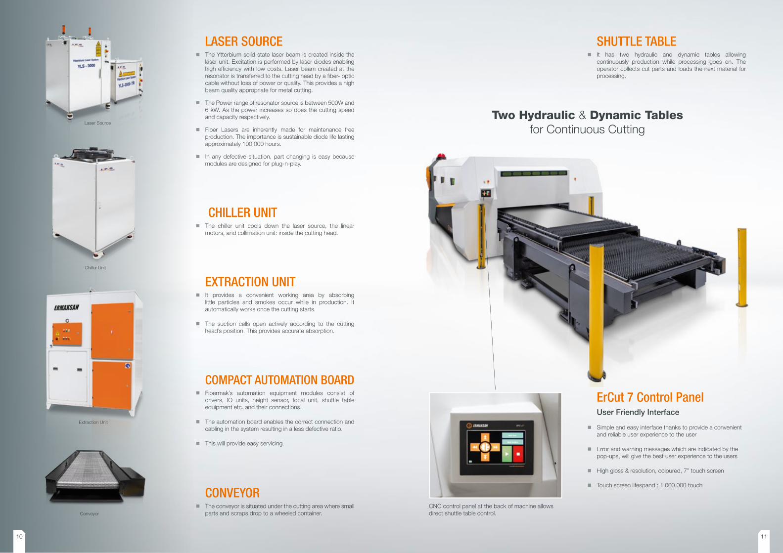
SHUTTLE TABLE � It has two hydraulic and dynamic tables allowing
continuously production while processing goes on. The operator collects cut parts and loads the next material for processing.
CNC control panel at the back of machine allows direct shuttle table control.
Two Hydraulic & Dynamic Tablesfor Continuous Cutting
ErCut 7 Control PanelUser Friendly Interface
� Simple and easy interface thanks to provide a convenient and reliable user experience to the user
� Error and warning messages which are indicated by the pop-ups, will give the best user experience to the users
� High gloss & resolution, coloured, 7” touch screen
� Touch screen lifespand : 1.000.000 touch
10 11
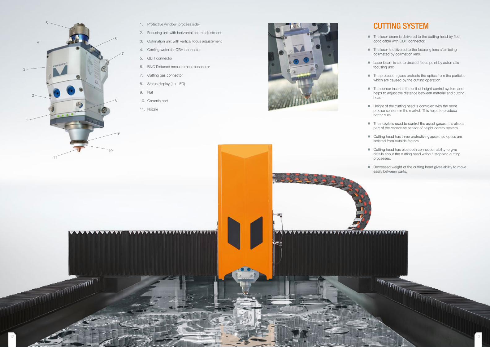
CUTTING SYSTEM � The laser beam is delivered to the cutting head by fiber
optic cable with QBH connector.
� The laser is delivered to the focusing lens after being collimated by collimation lens.
� Laser beam is set to desired focus point by automatic focusing unit.
� The protection glass protects the optics from the particles which are caused by the cutting operation.
� The sensor insert is the unit of height control system and helps to adjust the distance between material and cutting head.
� Height of the cutting head is controled with the most precise sensors in the market. This helps to produce better cuts.
� The nozzle is used to control the assist gases. It is also a part of the capacitive sensor of height control system.
� Cutting head has three protective glasses, so optics are isolated from outside factors.
� Cutting head has bluetooth connection ability to give details about the cutting head without stopping cutting processes.
� Decreased weight of the cutting head gives ability to move easily between parts.
1. Protective window (process side)
2. Focusing unit with horizontal beam adjustment
3. Collimation unit with vertical focus adjustement
4. Cooling water for QBH connector
5. QBH connector
6. BNC Distance measurement connector
7. Cutting gas connector
8. Status display (4 x LED)
9. Nut
10. Ceramic part
11. Nozzle
12 1312 13

HMI Screen
Axis Control with Joystick
Short Cut Buttons
Internal Monitor Screen
2 x USB input
USER FRIENDLY BUTTONS � Provide automatic shuttle table control, conveyor, extraction unit, laser unit control, focus reference, HSU calibration, shut
down and service positions, etc..
� Specific functions are easily reached with user friendly buttons, instead of surfing through the pages in HMI monitor.
CONTROLLER � The controller lets the operator command the machine.
� The controller is durable to all environmental effects.
� Active touch screen and functional keyboard.
� Short cut buttons provide ease-of-use. You can access
the desired functions faster and easier.
� Speed adjustment potentiometer allows you to adjust the
axes velocities even during the cutting operation.
� NC graphic shows online nesting.
All software on the controller
is developed by Ermaksan’s
Engineering Team. We
included the most
anticipated features that
an end user would expect.
Customer specific features
are engineered and added.
Axes movements Automatic Shuttle Table Laser and other functions Speed set up parameters
POWER IS UNDER YOUR CONTROL
14 15
CUTTING QUALITY
CAD/CAM SOFTWARE
Excellent flexibility and maximum performance
Minimum part consumption
Design error detection
Real-time and cost calculation
TECHNICAL FEATURES � All the options of CAD/CAM software are fully integrated
in one single program; designing a part, importing, nesting (automatic or manual) will be achieved from the same program without switching.
� Production Management Processes: CAD/CAM software is ready for connection to production management systems (ERP) by means of automatic processes.
� Teamwork: Available for operation as a standalone productivity cell, or as part of a network system.
� Part Management and sheet store with open databases: All part info is saved and organized in databases so that users can easily locate the part and sheet required.
� Large library of parametric parts in 2D with advanced options for geometry and editing.
� Calculation of real time and cost: CAD/CAM software calculates cutting time and cost of the entire sheet. Taking into account the number of piercings, the cut length, the mark length, the material costs, the hourly machine rate, the cost of consumables are based on the machine data.
AUTOMATIC NESTING � Manual and automatic nesting with great flexibility and
maximum performance.
� The perfect combination of automatic and semi- automatic nesting along with powerful manual nesting functions like: copying, moving, rotating, adjoining, etc
� CAD/CAM softwares’ automatic nesting optimises to the maximum arrangement of parts on the sheet.
� CAD/CAM software generates remnants on nestings. Just like for sheets, margins can be defined for remnants.
TECHNOLOGY � CAD/CAM software cut allows to configure and
manage the type and value of lead-in/lead outs for different types of contours.
� Common line cutting can be achieved on several parts or just limit to pairs of parts.
� It detects errors in the design and machining.
� With the help of the microjoints, parts will stay attached to the material which helps to collect parts easily.
Materials
Maximum cutting thickness
Laser Power500 W
Laser Power1 kW
Laser Power2 kW
Laser Power3 kW
Laser Power4 kW
Laser Power6 kW
Mild Steel 5 mm 8 mm 16 mm 18 mm 20 mm 25 mm
Stainless steel 2 mm 4 mm 8 mm 10 mm 12 mm 16 mm
Aluminum 2 mm 3 mm 8 mm 8 mm 10 mm 12 mm
Copper 1 mm 2 mm 6 mm 6 mm 6 mm 8 mm
Brass 1 mm 2 mm 6 mm 6 mm 6 mm 8 mm
Galvanized 1 mm 2 mm 4 mm 4 mm 4 mm 5 mm
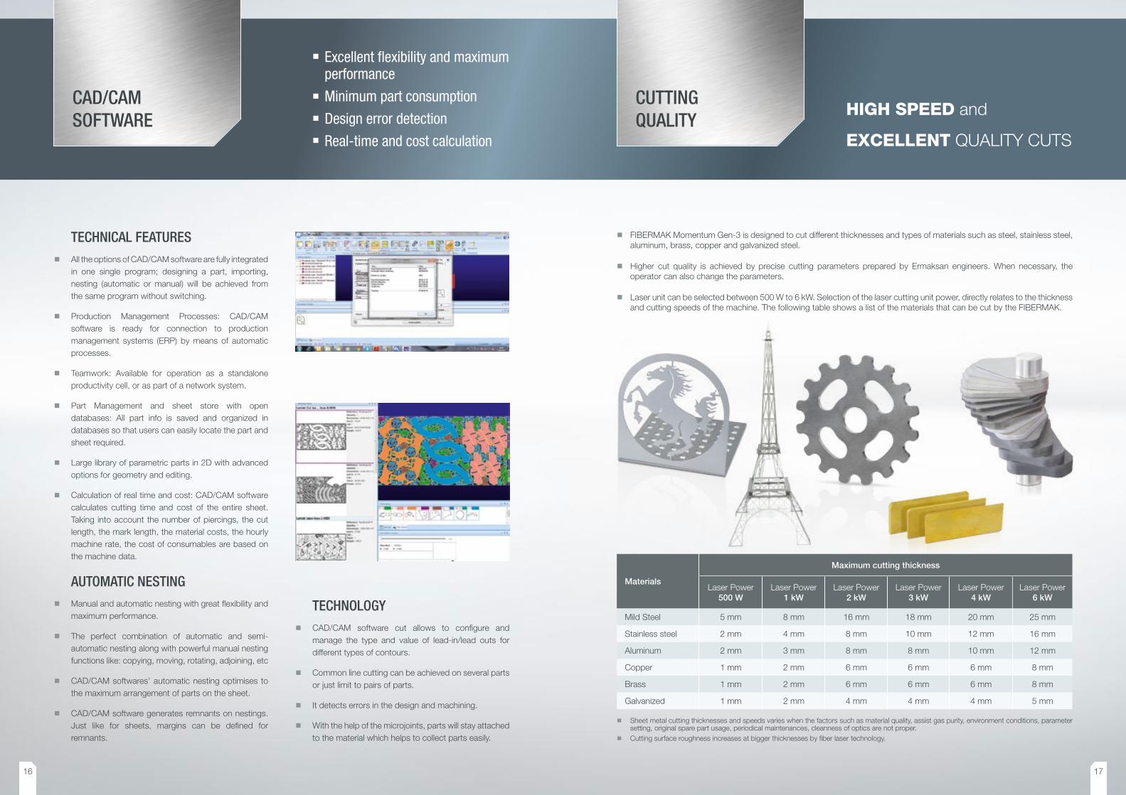
� FIBERMAK Momentum Gen-3 is designed to cut different thicknesses and types of materials such as steel, stainless steel, aluminum, brass, copper and galvanized steel.
� Higher cut quality is achieved by precise cutting parameters prepared by Ermaksan engineers. When necessary, the operator can also change the parameters.
� Laser unit can be selected between 500 W to 6 kW. Selection of the laser cutting unit power, directly relates to the thickness and cutting speeds of the machine. The following table shows a list of the materials that can be cut by the FIBERMAK.
� Sheet metal cutting thicknesses and speeds varies when the factors such as material quality, assist gas purity, environment conditions, parameter setting, original spare part usage, periodical maintenances, cleanness of optics are not proper.
� Cutting surface roughness increases at bigger thicknesses by fiber laser technology.
HIGH SPEED and
EXCELLENT QUALITY CUTS
16 17
Powerful motors provide high acceleration and speed
The most time loss is during the cutting and movement between the parts. Here, the acceleration of the axes is very important. Fibermak servo motor machines run, 1.5 G acceleration and 2.4 m/sec speed, linear motor machines run 2.5 G acceleration and 2.8 m/sec speed. This provide a serious time advantage passing through the parts.
Lift type transition enables high-speed movement between parts
Velocity and accelaration speed is important while moving between the parts. FIBERMAK Momentum Gen-3 uses part and aperture avoidance, raising the cutting head in the cycle, which allows you to reach maximum speed.
Ultra fast communication with EtherCAT
Using EtherCAT connections allows for ultra fast communication result in the faster control. Increasing the speed of control, ie Laser on/off speed, gas on/off speed etc. increases cutting capacities.
Fly-CUT feature
Both circular and equilateral parts can be cut with Fly-Cut feature of Fibermak Momentum Gen-3.
Cutting with dry air
Together with additional equipment (compressor, booster, filter, tank etc.) materials can be cut by dry air.
Machine is pre-prepared for this choice.
Cutting process is performed with active G code structure within minimum duration
G code flow is important when performing any action on the Fibermak with a CNC controller. G code flow on the Fibermak is designed to achieve the desired result using the shortest route. The time loss is minimized during operational transitions.
The cutting of part A is finished, the head moves to part B. The cutting head uses maximum acceleration and speed by using an Arc movement.
A B C
1 2
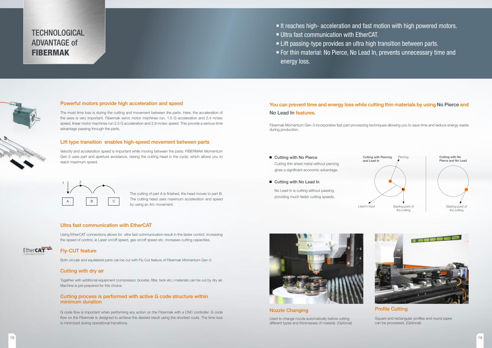
You can prevent time and energy loss while cutting thin materials by using No Pierce and
No Lead In features.
Fibermak Momentum Gen-3 incorporates fast part processing techniques allowing you to save time and reduce energy waste during production.
Cutting with No Pierce and No Lead
Starting point of the cutting
Cutting with Piercing and Lead In
Piercing
Lead In input Starting point of the cutting
TECHNOLOGICAL ADVANTAGE of FIBERMAK
It reaches high- acceleration and fast motion with high powered motors.Ultra fast communication with EtherCAT.Lift passing-type provides an ultra high transition between parts.For thin material: No Pierce, No Lead In, prevents unnecessary time and energy loss.
Cutting with No Pierce
Cutting thin sheet metal without piercing
gives a significant economic advantage.
Cutting with No Lead In
No Lead In is cutting without passing,
providing much faster cutting speeds.
Nozzle Changing
Used to change nozzle automatically before cutting different types and thicknesses of material. (Optional)
Profile Cutting
Square and rectangular profiles and round pipes can be processed. (Optional)
18 19

USER FRIENDLY Interface
Job ListUsed for continuing work automatically by the next program even for different material types and thicknesses by automatic parameter selecting.
Manual RemnantA cutting function used for removing the part from scrap plate after cutting process of material.
Job repeat and sheet angle detectionStarting point and sheet angle detection are all features of the Fibermak.
Only pierce featureAchieve high-quality cuts while cutting thick sheets.
Online parameter changingOperator can make changes to the parameters during the cutting process.
Graphical chase with NC Graphic Watching the real time cutting process graphically with NC Graphics.
Practical solutionsAxis move to the start point with pressing just one button.
Film BurningYou can use various film burning options.
Work report at PDF formatYou can keep detailed work report as PDF of the cutting process.
Wireless connection and serviceYou can connect to the machine remotely whenever needed with an Internet connection provided by wireless modem, USB type adapter or 3G modem. For servicing and software upgrading purposes.
Test runAxes movement simulating without cutting.
One Shot via HMIYou can easily make laser focal adjustment with one shot feature.
Piercing assistControlled airflow during piercing for blow away drosses and extend life spam of protection glass.
Easy interface designUser friendlyControl from single-pointPractical solutions
OPTIONAL EQUIPMENT
Air conditioner for electrical panel.
Metalix, Almacam etc. CAD/CAM software.
Automatic Nozzle Changer
LCM (laser cut monitor) sensor for piercing and cut
loss control
Sheet metal loading and unloading system
Full Automatic Sheet Metal Loading & Unloading System
The TOWERMAK is a system used for the unmanned loading/unloading management of metal sheets for 2D laser machines up to related machine dimensions; guarantees high level reliability, highly flexibility and easy to be used.
Linear motor technology.
0,5 kW, 1 kW, 2 kW, 3 kW, 4 kW and 6 kW laser
source options.
Extraction unit.
Light safety barrier.
Loading table with pneumatic ball transfers
High acceleration of 2,5 G on Servo Motorized models by Momentum Gen-3 G Force version is available as an option.
The productivity is increased average 15% per hour by higher acceleration and consequently the speed and gaining in time is higher.
Failure & warning messagesResonator, chiller, cutting head, shuttle table, extraction unit and programming failures are being monitor on CNC screen.
Running LaserNET from HMILaserNET program which is provide to reach the informations with laser unit also can be run via HMI.
Focus testsFocus optimization can be made manually via HMI. IT makes easier to access technical service, one-shot focus etc.
Real-time I/O informingThe digital-analog I/O information can be seen in real-time via HMI.
Record all errorsAll errors and warnings are recorded by the machine.
Feedrate changing during the cutYou can reduce or increase the speed during the cutting process.
Inch-Meter conversionFibermak can work in both imperial and metric systems.
LanguagesAs standard includes English, Russian, İtalian, Spanish and Polish. Other languages are possible on request.
Check partAfter cutting first part with this option feature you can check the parameters and cutting quality.
Gas control with PIDFaster, better and more precise gas control with PID.
NEW
20 21

TECHNICAL FEATURESLINEAR DRIVE
TECHNICAL FEATURESSERVO DRIVE
TECHNICAL FEATURES SM 500.3x1.5 SM 1000.3x1.5 SM 2000.3x1.5 SM 3000.3x1.5 SM 4000.3x1.5 SM 6000.3x1.5
RESONATOR Watt YLR 500 YLR 1000 YLS 2000 YLS 3000 YLS 4000 YLS 6000
POWER RANGE % 10-105 10-105 10-105 10-105 10-105 10-105
POWER STABILITY % 0,5 1 - 3 1 - 2 1 - 2 1 - 2 1 - 2
PULSE FREQUENCY RANGE kHz 5 5 5 5 5 5
LASER WAVE LENGTH nm 1070 ± 5 1070 ± 5 1075 ± 5 1075 ± 5 1075 ± 5 1075 ± 5
OUTPUT FIBER CORE DIAMETER μm 50 50 100 100 100 100
EXCITATION 0 Laser diode Laser diode Laser diode Laser diode Laser diode Laser diode
COOLING WATER FLOW RATE l/min 6 8 10 20 20 40
CUTTING CAPACITY (Maximum)
MILD STEEL mm 5 8 16 18 20 25
STAINLESS STEEL mm 2 4 8 10 12 16
ALUMINIUM mm 2 3 8 8 10 12
COPPER mm 1 2 6 6 6 8
BRASS mm 1 2 6 6 6 8
MAXIMUM WORKSHEET DIMENSIONS mm 3000 X 1500 3000 X 1500 3000 X 1500 3000 X 1500 3000 X 1500 3000 X 1500
MAXIMUM BURDEN CAPACITY kg 1500 1500 1500 1500 1500 1500
MACHINE AXES - 4-Axes [X, Y, Z, U ] 4-Axes [X, Y, Z, U ] 4-Axes [X, Y, Z, U ] 4-Axes [X, Y, Z,U ] 4-Axes [X, Y, Z, U ] 4-Axes [X, Y, Z, U ]
AXIAL MOVEMENTS
X, U AXES mm 3050 3050 3050 3050 3050 3050
Y AXIS mm 1530 1530 1530 1530 1530 1550
Z AXIS mm 150 150 150 150 150 150
ACCELERATIONS
X, U AXES G 1,5 1,5 1,5 1,5 1,5 1,5
Y AXIS G 1,5 1,5 1,5 1,5 1,5 1,5
Z AXIS G 1,5 1,5 1,5 1,5 1,5 2,5
MAXIMUM AXES VELOCITIES m/min141 (simultaneous)
( X, Y single axis velocity 100 m/min)
141 (simultaneous) ( X, Y single axis
velocity 100 m/min)
141 (simultaneous) ( X, Y single axis
velocity 100 m/min)
141 (simultaneous) ( X, Y single axis
velocity 100m/min)
141 (simultaneous) ( X, Y single axis
velocity 100 m/min)
141 (simultaneous) ( X, Y single axis
velocity 100 m/min)
POSITIONING ACCURACY mm/m ± 0,05 ± 0,05 ± 0,05 ± 0,05 ± 0,05 ± 0,05
REPETITION ACCURACY mm ± 0,025 ± 0,025 ± 0,025 ± 0,025 ± 0,025 ± 0,025
SHUTTLE TABLE (Automatic Loading - Unloading Unit)
palette 2 ( 35 sec ) 2 ( 35 sec ) 2 ( 35 sec ) 2 ( 35 sec ) 2 ( 35 sec ) 2 ( 35 sec )
ASSIST GAS
OXYGEN - 0,3-12 Bar 0,3-12 Bar 0,3-12 Bar 0,3-12 Bar 0,3-12 Bar 0,3-12 Bar
NITROGEN - 0,5-25 Bar 0,5-25 Bar 0,5-25 Bar 0,5-25 Bar 0,5-25 Bar 0,5-25 Bar
DRY AIR - 0,5-25 Bar 0,5-25 Bar 0,5-25 Bar 0,5-25 Bar 0,5-25 Bar 0,5-25 Bar
CUTTING HEAD -Precitec
Light Cutter HeadPrecitec
Light Cutter Head
Precitec Procutter Motorised Cutting
Head
Precitec Procutter Motorised Cutting
Head
Precitec Procutter Motorised Cutting
Head
Precitec Procutter Motorised Cutting
Head
CNC - BECKHOFF BECKHOFF BECKHOFF BECKHOFF BECKHOFF BECKHOFF
CAD/CAM SOFTWARE -LANTEK EXPERT
CUTLANTEK EXPERT
CUTLANTEK EXPERT
CUTLANTEK EXPERT
CUTLANTEK EXPERT
CUTLANTEK EXPERT
CUT
OPERATION VIA PANEL -15” touch screen
display, alphanumeric keyboard
15” touch screen display, alpha
numeric keyboard
15” touch screen display, alpha
numeric keyboard
15” touch screen display, alpha
numeric keyboard
15” touch screen display, alpha
numeric keyboard
15” touch screen display, alpha
numeric keyboard
TOTAL ELECTRIC POWER NECESSITY
kW 12 14 18 20 22 28
MACHINE DIMENSIONS ( L x W x H )
mm9190 X 3710 X
22009190 X 3710 X
22009190 X 3710 X
22009190 X 3710 X
22009190 X 3710 X
22009190 X 3710 X
2200
MACHINE WEIGHT kg 11200 11200 11200 11200 11200 11200
*All specs are subject to change without notice
TECHNICAL FEATURES LM 500.3x1.5 LM 1000.3x1.5 LM 2000.3x1.5 LM 3000.3x1.5 LM 4000.3x1.5 LM 6000.3x1.5
RESONATOR Watt YLR 500 YLR 1000 YLS 2000 YLS 3000 YLS 4000 YLS 6000
POWER RANGE % 10-105 10-105 10-105 10-105 10-105 10-105
POWER STABILITY % 0,5 1 - 3 1 - 2 1 - 2 1 - 2 1 - 2
PULSE FREQUENCY RANGE kHz 5 5 5 5 5 5
LASER WAVE LENGTH nm 1070 ± 5 1070 ± 5 1075 ± 5 1075 ± 5 1075 ± 5 1075 ± 5
OUTPUT FIBER CORE DIAMETER μm 50 50 100 100 100 100
EXCITATION 0 Laser diode Laser diode Laser diode Laser diode Laser diode Laser diode
COOLING WATER FLOW RATE l/min 6 8 10 20 20 40
CUTTING CAPACITY (Maximum)
MILD STEEL mm 5 8 16 18 20 25
STAINLESS STEEL mm 2 4 8 10 12 16
ALUMINIUM mm 2 3 8 8 10 12
COPPER mm 1 2 6 6 6 8
BRASS mm 1 2 6 6 6 8
MAXIMUM WORKSHEET DIMENSIONS mm 3000 X 1500 3000 X 1500 3000 X 1500 3000 X 1500 3000 X 1500 3000 X 1500
MAXIMUM BURDEN CAPACITY kg 1500 1500 1500 1500 1500 1500
MACHINE AXES - 4-Axes [X,Y,Z,U] 4-Axes [X,Y,Z,U] 4-Axes [X,Y,Z,U] 4-Axes [X,Y,Z,U] 4-Axes [X,Y,Z,U] 4-Axes [X,Y,Z,U]
AXIAL MOVEMENTS
X, U AXES mm 3050 3050 3050 3050 3050 3050
Y AXIS mm 1530 1530 1530 1530 1530 1530
Z AXIS mm 150 150 150 150 150 150
ACCELERATIONS
X, U AXES G 2,5 2,5 2,5 2,5 2,5 2
Y AXIS G 2,5 2,5 2,5 2,5 2,5 2
Z AXIS G 2,5 2,5 2,5 2,5 2,5 2
MAXIMUM AXES VELOCITIES m/min170 (simultaneous)
( X, Y single axis velocity 120m/min)
170 (simultaneous) ( X, Y single axis
velocity 120m/min)
170 (simultaneous) ( X, Y single axis
velocity 120m/min)
170 (simultaneous) ( X, Y single axis
velocity 120m/min)
170 (simultaneous) ( X, Y single axis
velocity 120m/min)
170 (simultaneous) ( X, Y single axis
velocity 120m/min)
POSITIONING ACCURACY mm/m ± 0,03 ± 0,03 ± 0,03 ± 0,03 ± 0,03 ± 0,03
REPETITION ACCURACY mm ± 0,015 ± 0,015 ± 0,015 ± 0,015 ± 0,015 ± 0,015
SHUTTLE TABLE (Automatic Loading - Unloading Unit)
pal-ette
2 ( 35 sec ) 2 ( 35 sec ) 2 ( 35 sec 2 ( 35 sec ) 2 ( 35 sec ) 2 ( 35 sec )
ASSIST GAS
OXYGEN - 0,3-12 Bar 0,3-12 Bar 0,3-12 Bar 0,3-12 Bar 0,3-12 Bar 0,3-12 Bar
NITROGEN - 0,5-25 Bar 0,5-25 Bar 0,5-25 Bar 0,5-25 Bar 0,5-25 Bar 0,5-25 Bar
DRY AIR - 0,5-25 Bar 0,5-25 Bar 0,5-25 Bar 0,5-25 Bar 0,5-25 Bar 0,5-25 Bar
CUTTING HEAD -Precitec
Light Cutter HeadPrecitec
Light Cutter Head
Precitec Procutter Motorised Cutting
Head
Precitec Procutter Motorised Cutting
Head
Precitec Procutter Motorised Cutting
Head
Precitec Procutter Motorised Cutting
Head
CNC - BECKHOFF BECKHOFF BECKHOFF BECKHOFF BECKHOFF BECKHOFF
CAD/CAM SOFTWARE -LANTEK EXPERT
CUTLANTEK EXPERT
CUTLANTEK EXPERT
CUTLANTEK EXPERT
CUTLANTEK EXPERT
CUTLANTEK EXPERT
CUT
OPERATION VIA PANEL -15” touch screen display, alpha nu-meric keyboard
15” touch screen display, alpha nu-meric keyboard
15” touch screen display, alpha nu-meric keyboard
15” touch screen display, alpha nu-meric keyboard
15” touch screen display, alpha nu-meric keyboard
15” touch screen display, alpha nu-meric keyboard
TOTAL ELECTRIC POWER NECES-SITY
kW 17 17 21 31 33.7 33.7
MACHINE DIMENSIONS ( L x W x H ) mm9190 X 3710 X
22009190 X 3710 X
22009190 X 3710 X
22009190 X 3710 X
22009190 X 3710 X
22009190 X 3710 X
2200
MACHINE WEIGHT kg 11200 11200 11200 11200 11200 11200
*All specs are subject to change without notice
22 23

Fibe
rmak
- E
NG
© A
ll rig
hts
rese
rved
.
1
0/20
15
/ermaksan.com.tr /ermaksanmachine /ErmaksanTV
Organize Sanayi Bölgesi, Lacivert Cad. No:6 Nilüfer, Bursa / TURKEYT: +90 224 294 75 00 (pbx) F: +90 224 294 75 44www.ermaksan.com.tr | [email protected]
M E T A L F A B R I C A T I N G M A C H I N E R Y
innovative technologies.
Innovative Technologies | www.ermaksan.com.tr | Laser Series


