Download - FENCING ASSEMBLY INSTRUCTIONS - Niles Fence
310 North Pleasant Avenue • P.O. Box 191 • Niles, OH 44446-0191 • Toll Free: 1-800-321-7464 • Fax: 330-299-0329 • [email protected] • www.nilesfence.com
2
FENCING ASSEMBLY INSTRUCTIONS
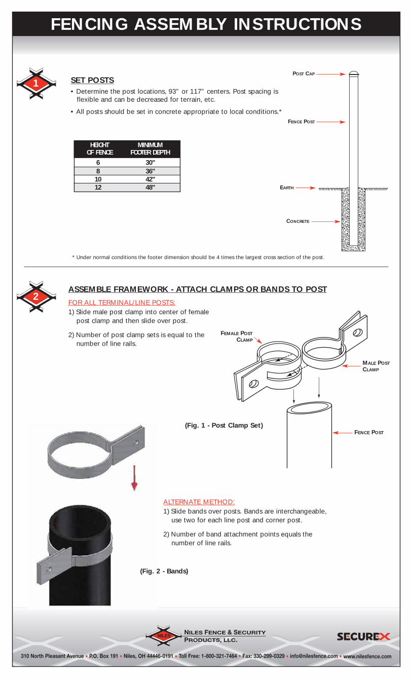
SET POSTS• Determine the post locations, 93" or 117" centers. Post spacing is
flexible and can be decreased for terrain, etc.
• All posts should be set in concrete appropriate to local conditions.*
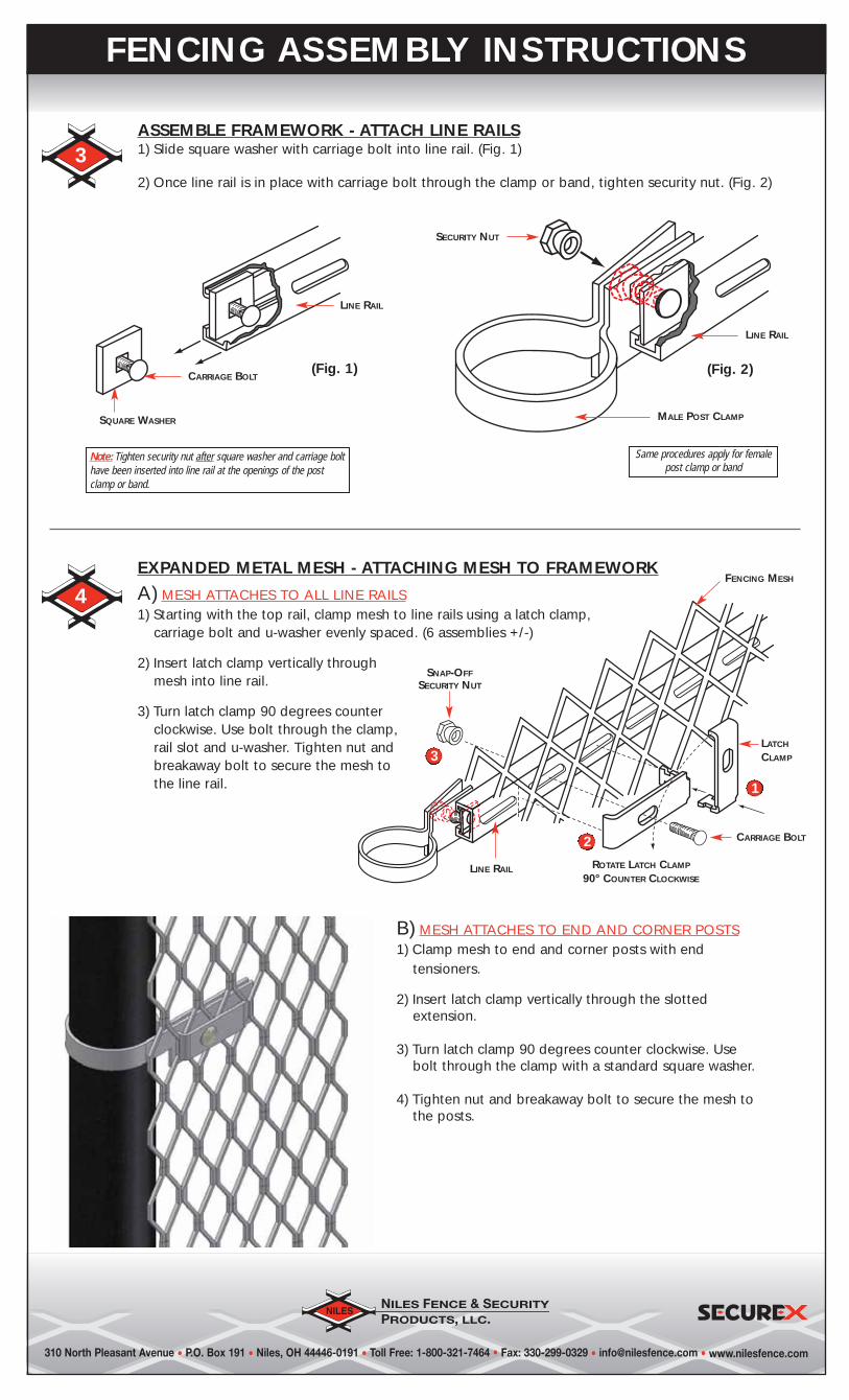
ASSEMBLE FRAMEWORK - ATTACH CLAMPS OR BANDS TO POST
FOR ALL TERMINAL/LINE POSTS:1) Slide male post clamp into center of female
post clamp and then slide over post.
2) Number of post clamp sets is equal to thenumber of line rails.
1
ALTERNATE METHOD:1) Slide bands over posts. Bands are interchangeable,
use two for each line post and corner post.
2) Number of band attachment points equals thenumber of line rails.
FENCE POST
MALE POSTCLAMP
FEMALE POSTCLAMP
(Fig. 1 - Post Clamp Set)
POST CAP
FENCE POST
EARTH
CONCRETE
HEIGHT MINIMUMOF FENCE FOOTER DEPTH
6 30"8 36"10 42"12 48"
* Under normal conditions the footer dimension should be 4 times the largest cross section of the post.
(Fig. 2 - Bands)
310 North Pleasant Avenue • P.O. Box 191 • Niles, OH 44446-0191 • Toll Free: 1-800-321-7464 • Fax: 330-299-0329 • [email protected] • www.nilesfence.com
FENCING ASSEMBLY INSTRUCTIONS
3ASSEMBLE FRAMEWORK - ATTACH LINE RAILS1) Slide square washer with carriage bolt into line rail. (Fig. 1)
2) Once line rail is in place with carriage bolt through the clamp or band, tighten security nut. (Fig. 2)
Same procedures apply for femalepost clamp or band
Note: Tighten security nut after square washer and carriage bolthave been inserted into line rail at the openings of the postclamp or band.
ROTATE LATCH CLAMP
90° COUNTER CLOCKWISE
CARRIAGE BOLT
LINE RAIL
1
2
3
FENCING MESH
LATCH
CLAMP
B) MESH ATTACHES TO END AND CORNER POSTS1) Clamp mesh to end and corner posts with end
tensioners.
2) Insert latch clamp vertically through the slottedextension.
3) Turn latch clamp 90 degrees counter clockwise. Usebolt through the clamp with a standard square washer.
4) Tighten nut and breakaway bolt to secure the mesh tothe posts.
(Fig. 1)
LINE RAIL
CARRIAGE BOLT
SQUARE WASHER
SECURITY NUT
(Fig. 2)
LINE RAIL
MALE POST CLAMP
4EXPANDED METAL MESH - ATTACHING MESH TO FRAMEWORK
A) MESH ATTACHES TO ALL LINE RAILS1) Starting with the top rail, clamp mesh to line rails using a latch clamp,
carriage bolt and u-washer evenly spaced. (6 assemblies +/-)
2) Insert latch clamp vertically throughmesh into line rail.
3) Turn latch clamp 90 degrees counterclockwise. Use bolt through the clamp,rail slot and u-washer. Tighten nut andbreakaway bolt to secure the mesh tothe line rail.
SNAP-OFFSECURITY NUT
310 North Pleasant Avenue • P.O. Box 191 • Niles, OH 44446-0191 • Toll Free: 1-800-321-7464 • Fax: 330-299-0329 • [email protected] • www.nilesfence.com
FENCING ASSEMBLY INSTRUCTIONS
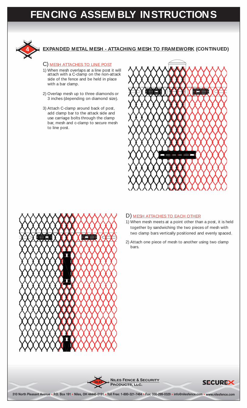
4 EXPANDED METAL MESH - ATTACHING MESH TO FRAMEWORK (CONTINUED)
C) MESH ATTACHES TO LINE POST1) When mesh overlaps at a line post it will
attach with a C-clamp on the non-attackside of the fence and be held in placewith a bar clamp.
2) Overlap mesh up to three diamonds or3 inches (depending on diamond size).
3) Attach C-clamp around back of post,add clamp bar to the attack side anduse carriage bolts through the clampbar, mesh and c-clamp to secure meshto line post.
D) MESH ATTACHES TO EACH OTHER1) When mesh meets at a point other than a post, it is held
together by sandwiching the two pieces of mesh withtwo clamp bars vertically positioned and evenly spaced.
2) Attach one piece of mesh to another using two clampbars.
310 North Pleasant Avenue • P.O. Box 191 • Niles, OH 44446-0191 • Toll Free: 1-800-321-7464 • Fax: 330-299-0329 • [email protected] • www.nilesfence.com
FENCING ASSEMBLY INSTRUCTIONS
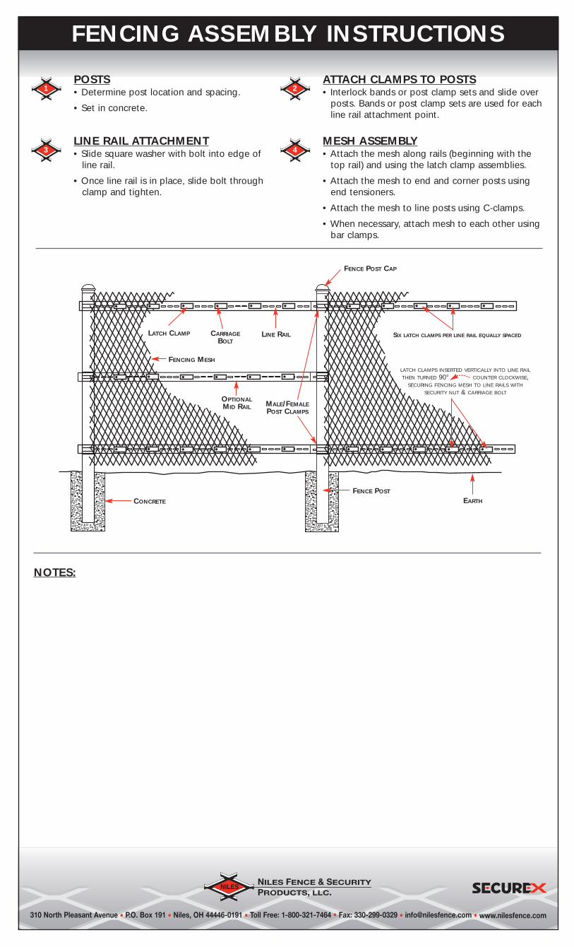
1POSTS• Determine post location and spacing.
• Set in concrete.
NOTES:
3LINE RAIL ATTACHMENT• Slide square washer with bolt into edge of
line rail.
• Once line rail is in place, slide bolt throughclamp and tighten.
4MESH ASSEMBLY• Attach the mesh along rails (beginning with the
top rail) and using the latch clamp assemblies.
• Attach the mesh to end and corner posts usingend tensioners.
• Attach the mesh to line posts using C-clamps.
• When necessary, attach mesh to each other usingbar clamps.
2ATTACH CLAMPS TO POSTS• Interlock bands or post clamp sets and slide over
posts. Bands or post clamp sets are used for eachline rail attachment point.
LATCH CLAMP LINE RAIL
OPTIONALMID RAIL
CARRIAGEBOLT
FENCING MESH
MALE/FEMALEPOST CLAMPS
SIX LATCH CLAMPS PER LINE RAIL EQUALLY SPACED
LATCH CLAMPS INSERTED VERTICALLY INTO LINE RAIL
THEN TURNED 90° COUNTER CLOCKWISE,SECURING FENCING MESH TO LINE RAILS WITH
SECURITY NUT & CARRIAGE BOLT
FENCE POST
CONCRETE
FENCE POST CAP
EARTH
310 North Pleasant Avenue • P.O. Box 191 • Niles, OH 44446-0191 • Toll Free: 1-800-321-7464 • Fax: 330-299-0329 • [email protected] • www.nilesfence.com
STEEP GRADIENTS REQUIRE SPECIALLY
MANUFACTURED PANELS
CONCRETE
CUT AWAY
OR
BURY MESH
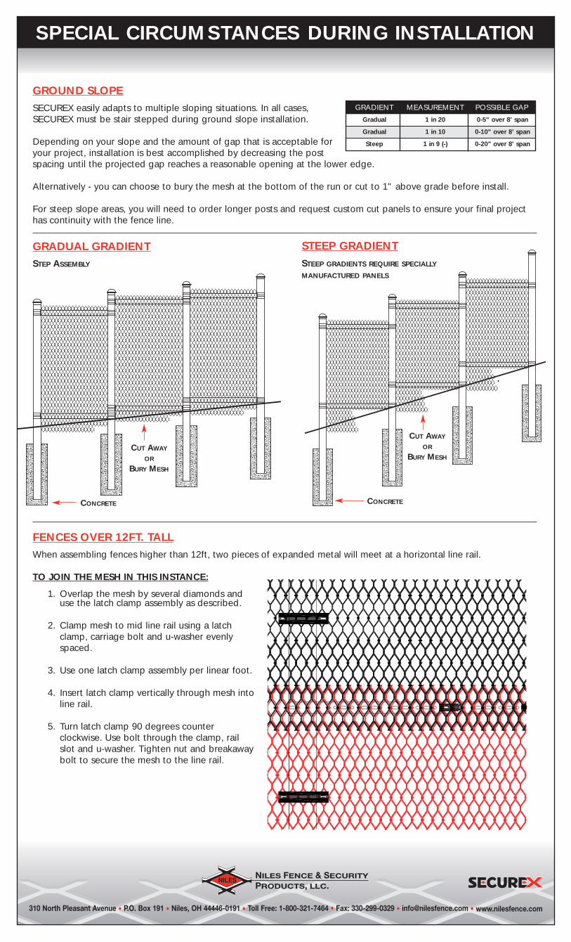
GROUND SLOPESECUREX easily adapts to multiple sloping situations. In all cases,SECUREX must be stair stepped during ground slope installation.
Depending on your slope and the amount of gap that is acceptable foryour project, installation is best accomplished by decreasing the postspacing until the projected gap reaches a reasonable opening at the lower edge.
Alternatively - you can choose to bury the mesh at the bottom of the run or cut to 1" above grade before install.
For steep slope areas, you will need to order longer posts and request custom cut panels to ensure your final projecthas continuity with the fence line.
FENCES OVER 12FT. TALLWhen assembling fences higher than 12ft, two pieces of expanded metal will meet at a horizontal line rail.
TO JOIN THE MESH IN THIS INSTANCE:
1. Overlap the mesh by several diamonds anduse the latch clamp assembly as described.
2. Clamp mesh to mid line rail using a latchclamp, carriage bolt and u-washer evenlyspaced.
3. Use one latch clamp assembly per linear foot.
4. Insert latch clamp vertically through mesh intoline rail.
5. Turn latch clamp 90 degrees counterclockwise. Use bolt through the clamp, railslot and u-washer. Tighten nut and breakawaybolt to secure the mesh to the line rail.
STEEP GRADIENT
GRADIENT MEASUREMENT POSSIBLE GAP
Gradual 1 in 20 0-5" over 8' span
Gradual 1 in 10 0-10" over 8' span
Steep 1 in 9 (-) 0-20" over 8' span
SPECIAL CIRCUMSTANCES DURING INSTALLATION
STEP ASSEMBLY
CUT AWAY
OR
BURY MESH
CONCRETE
GRADUAL GRADIENT
310 North Pleasant Avenue • P.O. Box 191 • Niles, OH 44446-0191 • Toll Free: 1-800-321-7464 • Fax: 330-299-0329 • [email protected] • www.nilesfence.com
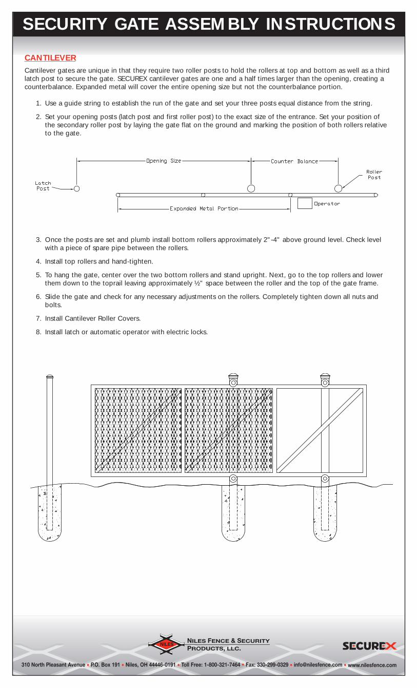
CANTILEVERCantilever gates are unique in that they require two roller posts to hold the rollers at top and bottom as well as a thirdlatch post to secure the gate. SECUREX cantilever gates are one and a half times larger than the opening, creating acounterbalance. Expanded metal will cover the entire opening size but not the counterbalance portion.
1. Use a guide string to establish the run of the gate and set your three posts equal distance from the string.
2. Set your opening posts (latch post and first roller post) to the exact size of the entrance. Set your position ofthe secondary roller post by laying the gate flat on the ground and marking the position of both rollers relativeto the gate.
3. Once the posts are set and plumb install bottom rollers approximately 2"-4" above ground level. Check levelwith a piece of spare pipe between the rollers.
4. Install top rollers and hand-tighten.
5. To hang the gate, center over the two bottom rollers and stand upright. Next, go to the top rollers and lowerthem down to the toprail leaving approximately ½" space between the roller and the top of the gate frame.
6. Slide the gate and check for any necessary adjustments on the rollers. Completely tighten down all nuts andbolts.
7. Install Cantilever Roller Covers.
8. Install latch or automatic operator with electric locks.
SECURITY GATE ASSEMBLY INSTRUCTIONS
310 North Pleasant Avenue • P.O. Box 191 • Niles, OH 44446-0191 • Toll Free: 1-800-321-7464 • Fax: 330-299-0329 • [email protected] • www.nilesfence.com
SECURITY GATE ASSEMBLY INSTRUCTIONS
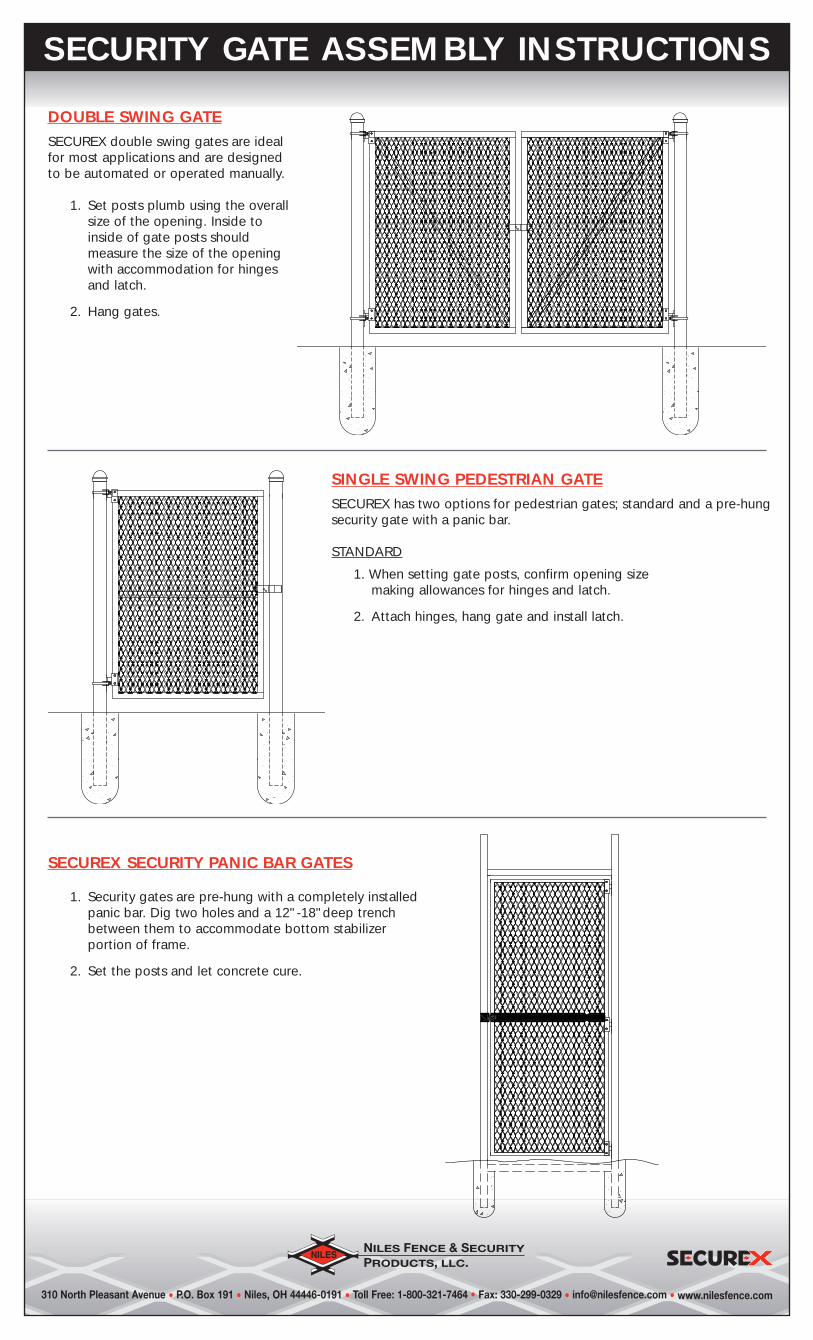
DOUBLE SWING GATESECUREX double swing gates are idealfor most applications and are designedto be automated or operated manually.
1. Set posts plumb using the overallsize of the opening. Inside toinside of gate posts shouldmeasure the size of the openingwith accommodation for hingesand latch.
2. Hang gates.
SINGLE SWING PEDESTRIAN GATESECUREX has two options for pedestrian gates; standard and a pre-hungsecurity gate with a panic bar.
STANDARD
1. When setting gate posts, confirm opening sizemaking allowances for hinges and latch.
2. Attach hinges, hang gate and install latch.
SECUREX SECURITY PANIC BAR GATES
1. Security gates are pre-hung with a completely installedpanic bar. Dig two holes and a 12"-18"deep trenchbetween them to accommodate bottom stabilizerportion of frame.
2. Set the posts and let concrete cure.


