ffV-ft/XO (bib
K>/7-/^O C7C>
TECHNICAL REPORT ARLCB-TR-82029
FAILURE DESIGN OF THICK-WALLED CYLINDERS
CONSIDERING THE OD AS A FAILURE INITIATION SITE
J. A. Kapp S. L. Pu
TECHNICAL LIBRARY
September 1982
US ARMY ARMAMENT RESEARCH AND DEVELOPMENT COMMAND LARfiE CALIBER WEAPON SYSTEMS LABORATORY
IIN^T WEAPONS LABORATORY WATERVLIET, N. Y. 12189
AMCMS No. 72801213000
PRON No. 1A1258731A1A
APPROVED FOR PUBLIC RELEASE; DISTRIBUTION UNLIMITED
DISCLAIMER
The findings in this report are not to be construed ao an official
Department of the Anny position unless so designated by other author-
ized documents.
The use of trade nanie(s) and/or manufacture^) does not consti-
tute an official indorsement or approval.
DISPOSITION
Destroy this report when it is no longer needed. Do not return it
to the originator.
SECURITY CLASSIFICATION OF THIS PAGE (When Data Entered)
REPORT DOCUMENTATION PAGE 1. REPORT NUMBER
ARLCB-TR-82029
2. GOVT ACCESSION NO
4. TITLE (and Sublltle)
FAILURE DESIGN OF THICK-WALLED CYLINDERS CONSIDERING THE OD AS A FAILURE INITIATION SITE
7. AUTHORfs)
J. A. Kapp and S. L. Pu
9. PERFORMING ORGANIZATION NAME AND ADDRESS
US Army Armament Research & Development Command Benet Weapons Laboratory, DRDAR-LCB-TL Watervliet, NY 12189 tl. CONTROLLING OFFICE NAME AND ADDRESS
US Army Armament Research & Development Command Large Caliber Weapon Systems Laboratory Dover, NJ 07801 14. MONITORING AGENCY NAME 4 ADDRESSf/f dlitermt from Controlling Oflice)
16. DISTRIBUTION STATEMENT (of thla Report)
Approved for public release; distribution unlimited
READ INSTRUCTIONS BEFORE COMPLETING FORM
3. RECIPIENT'S CATALOG NUMBER
S. TYPE OF REPORT 4 PERIOD COVERED
Final
6. PERFORMING ORG. REPORT NUMBER
8. CONTRACT OR GRANT NUMBERCoJ
10. PROGRAM ELEMENT, PROJECT, TASK AREA 4 WORK UNIT NUMBERS
AMCMS No. 72801213000 PRON No. 1A1258731A1A
12. REPORT DATE
September 1982 13. NUMBER OF PAGES
31 15. SECURITY CLASS, (of thla report)
UNCLASSIFIED ISa. DECLASSIFI CATION/DOWN GRADING
SCHEDULE
17. DISTRIBUTION STATEMENT (of the abatract entered In Block 20, It different from Report)
18. SUPPLEMENTARY NOTES
Presented at ASME Pressure Vessel Design Conference, Orlando, FL, June 1982, Published in proceedings of the conference.
19. KEY WORDS (Continue on reverie aide if necessary and Identity by block number)
Fatigue Thick-Walled Cylinders Fracture Mechanics Crack Initiation Crack Growth 20, ABSTRACT fCazHbtum an revere* mt<tm tt n—■<—y ami Identify by block number)
The outside diameter (0D) of thick-walled pressure vessels is considered as the initiation site for fatigue failure of the cylinder. 0D failures can occur in pressurized cylinders which have discontinuities machined on their outside surfaces, and have been strengthened by the autofrettage process. Both the crack initiation and crack propagation phases are discussed. To do this, finite element stress solutions for 0D notched thick-walled cylinders and
(CONT'D ON REVERSE)
DD.^1473 EDITION OF » MOV 65 IS OBSOLETE UNCLASSIFIED
SECURITY CLASSIFICATION OF THIS PAGE (When Data Entered)

SECURITY CLASSIFICATION OF THIS PAGEfHTian Dalm Enlend)
20. ABSTRACT (CONT'D)
specialized fracture mechanics solutions are presented. Life and crack, growth predictions based on these analyses are compared to previously performed experiments.
SECURITY CLASSIFICATION OF THIS P AGEfWhen Data Entered)

TABLE OF CONTENTS Page
1 INTRODUCTION
STRESS ANALYSIS 5
PREDICTING THE FAILURE OF CYLINDERS WITH OD DISCONTINUITIES 13
CONCLUSIONS 19
REFERENCES 21
TABLES
I. K SOLUTIONS FOR EXTERNALLY CRACKED THICK-WALLED CYLINDERS 9
II. COEFFICIENTS FOR THE EXPRESSIONS FOR THE STRESS INTENSITY 11 FACTORS
III. STRESS CONCENTRATION FACTORS kt AND STRESS RELIEF FACTORS . 12 Rs FOR AN OD NOTCHED CYLINDER, W = 1.74, ROOT RADIUS OF THE NOTCH = 0.013 t
LIST OF ILLUSTRATIONS
1. A Thick-Walled Cylinder Containing Various OD Discontinuities. 25
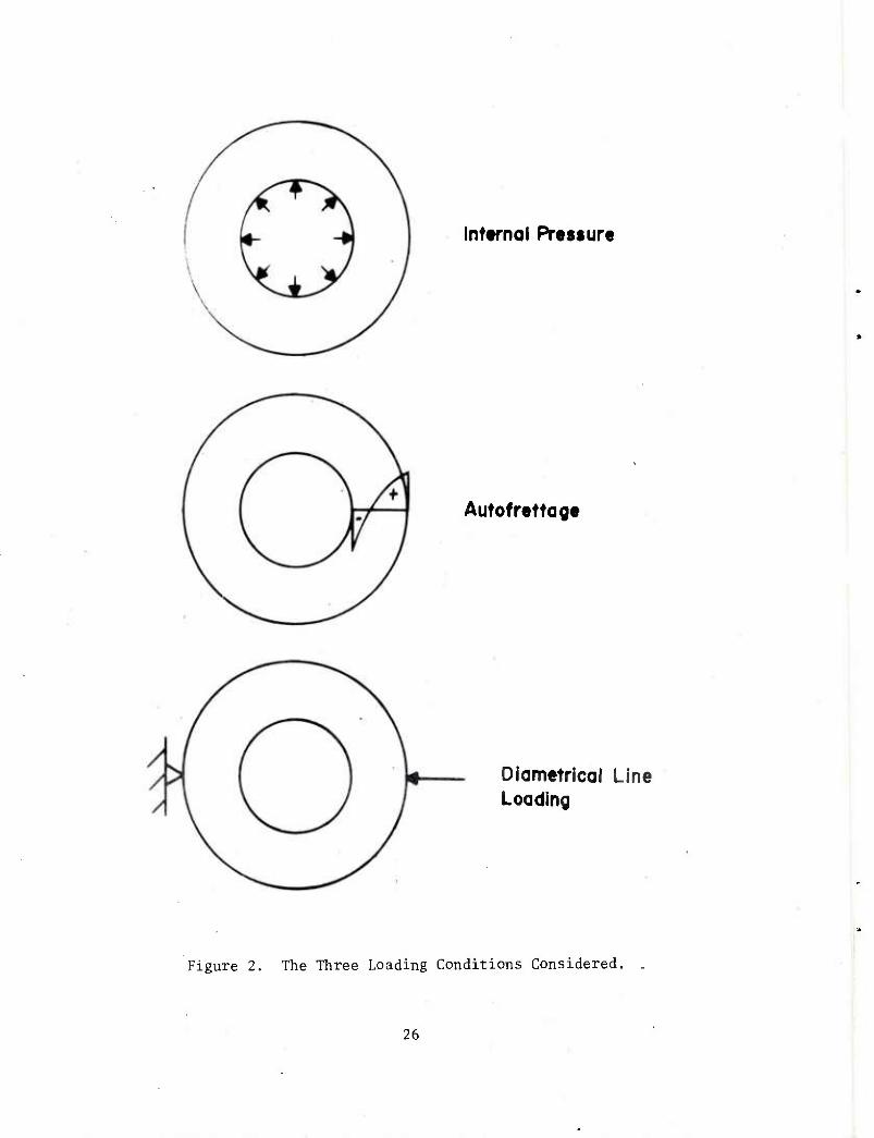
2. The Three Loading Conditions Considered. 26
3. Comparison of Measured Fatigue Life and the Estimated Fatigue 27 Life Expanding on Fuch's Crack Initiation Criteria.32
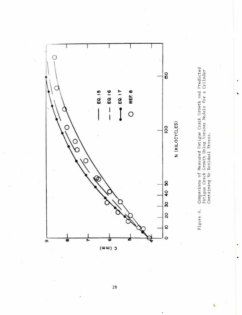
4. Comparison of Measured Fatigue Crack Growth and Predicted 28 Fatigue Crack Growth Using Various Models for a Cylinder Containing No Residual Stress. •
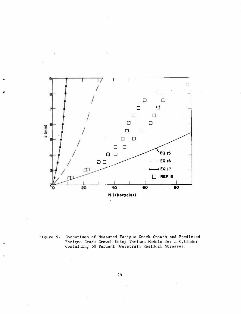
5. Comparison of Measured Fatigue Crack Growth and Predicted 29 Fatigue Crack Growth Using Various Models for a Cylinder Containing 50 Percent Overstrain Residual Stresses.
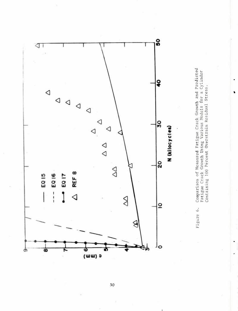
6. Comparison of Measured Fatigue Crack Growth and Predicted 30 Fatigue Crack Growth Using Various Models for a Cylinder Containing 100 Percent Overstrain Residual Stress.

INTRODUCTION
Thick-walled cylinders are often used to contain very high pressures.^
The elastic stress solution for such cylinders was developed by Lame' and is
well known (see for example, Reference 2). This solution shows that for a
smooth cylinder the maximum stress occurs in the tangential direction at the
inside diameter (ID). Such cylinders subjected to cyclic internal pressuriza-
tion fail by crack initiation and growth from the ID.^ To increase the
fatigue life of cylinders, compressive residual stresses at the ID are often
introduced by autofrettage.^ As a result of the autofrettage, a tensile
residual stress is induced at the OD. Sometimes after the autofrettage
process, cylinders are machined on the OD producing stress concentrations,
such as keyways, notches, holes, or threads. In these cylinders, the combina-
tion of tensile operating stress, tensile residual stress, and stress concen-
tration often result in the OD, rather than the ID, being the fatigue failure
initiation site.^-^ OD initiated failures are less desirable since they occur
often, but not exclusively accompanied by very little stable crack growth.
Catastrophic failure occurs shortly after the initiation and coalescence of
many short penny shaped cracks to form a shallow straight-fronted crack.^
OD discontinuities in thick cylinders have been the subject of several
experimental5~9 and theoretical^*1^-20 studies. The bulk of the experimental
work5-7,9 has dealt with the effects of stress concentrations of fatigue crack
initiation, while one study has discussed crack growth from the OD. All of
these studies were on cylinders which either had been autofrettaged-"-" or were
References are listed at the end of this report.

loaded In such a way as to simulate the presence of autofrettage residual
stresses. The theoretical work has included internally pressurized cylinders
containing OD cracks,8»10~12»1^>15«20 autofrettaged cylinders with OD
cracks,i"»19,20 and autofrettaged cylinders with stress concentrations at the
OD.13,17,18
In the experimental studies, Brown^ and Brown and McAlonie^'^ have
fatigue tested actual autofrettaged cannon barrels containing OD notches.
Their results showed that these cylinders failed by crack initiation at the
notches followed by very little crack growth before gross through thickness
fracture. In an attempt to model this behavior experimentally, without the
expense of testing large cannon barrels, Kapp and Underwood^ have used a simu-
lation specimen. This specimen was a modified C-shaped fracture toughness
specimen,21 with the same OD notch studied by Brown and McAlonie.'' By loading
this specimen properly, the same stresses were developed at the OD notch as
occurred in the actual cylinder. The agreement with the fatigue data in
Reference 6 was excellent. By using this specimen, design variables such as
the degree of autofrettage or notch geometry could be tested very efficiently.
These variables were tested and showed that fatigue life can be changed much
more by modifying the stress concentration of the OD configuration, than by
reducing the amount of autofrettage. In the other experimental study, Kapp
and Eisenstadto measured fatigue crack growth rates in autofrettaged rings
with radial cracks emanating from the OD. The results showed that auto-
frettage could increase the fatigue crack growth rate by as much as an order
of magnitude when compared to the results obtained in specimens which
contained no autofrettage residual stresses.
The first theoretical study, by Emery and Segedin,10 was a stress
intensity factor, K, solution for thick- and thin-walled cylinders loaded by
internal pressure using a finite difference method. When their solutions were
compared to K solutions developed using finite elements"»^°>20 and mapping
collocation solutions^ »^ »^ the agreement was not good, although the finite
element and collocation results normally agree within two percent. The
initial collocation results^ were for cylinders containing from one to four
cracks loaded by internal pressure, with various diameter ratios, W, (W «
OD/ID). The first finite element study8 was for a single crack in a cylinder
with W = 2.
Subsequent numerical K solutions1*'J1^«20 included auLofrettage residual
stresses and internal pressure for as many as 40 standard cracks In cylinders
of various diameter ratios. Solutions for the autofrettage cases required the
development of some specialized stress analysis techniques. Since auto-
frettage residual stresses exist in a cylinder under the action of no external
active loads, the special stress analysis methods were needed. Two basic
methods were developed, superposition and simulation. Using the superposition
method,^J1^ a pressure was applied to the crack surfaces which was equivalent
to the negative of the stress which would have acted at the same location in a
cylinder with no crack present. In a modification of this, Pu^O used a weight
function approach which was somewhat different than the method used by
Parker,16J1^ yielding the same results. Using the simulation
technique1*'*1^>20 the autofrettage residual stresses were simulated through the
use of an active thermal distribution. The method, developed independently by
Parker and Farrow22 and Hussain et al,23 showed that a properly defined, loga-
rithraically varying temperature distribution produces exactly the same stress
distribution as autofrettage in an uncracked cylinder. By applying this same
temperature distribution to a cracked cylinder, the K solution developed
agreed very well with the superposition solutions. Autofrettage resulted in
very high K values, with the highest values resulting from the higher degrees
of autofrettage. Also, the most severe case occurred when there were two
diametrically opposed cracks.
The theoretical studies on notched cylinders^,17,18 are rauch less exten-
sive than on cracked cylinders. In the first paper,13 stresses in OD notches
were estimated, while in the more involved studies,^'^ the stresses were
calculated using the finite element method and the thermal loading simulation
method.22,23 The solutions showed that the OD notches studied concentrated
the stress to the extent that the notches became the highest stressed point in
the cylinder, even if the cylinder was not autofrettaged. The autofrettage
results indicated that stresses exceeding the yield strength of the cylinder
material acted at the OD notches. Furthermore, the presence of the notches
relieved the autofrettage residual stresses throughout the cylinder by as much
as 30 percent.
In this report we will attempt to relate the theoretical and experimental
work that has been performed to develop a guideline that may be used in the
design of thick-walled cylinders containing OD discontinuities. The
discussion will involve three main areas: special stress analysis methods,
failure by fatigue crack initiation, and failure by fatigue crack growth.
STRESS ANALYSIS
A thick-walled cylinder of radius ratio (b/a) of two is shown in Figure
1, which also defines the geometric parameters used in the equations below.
Three loading conditions will be discussed: internal pressure, autofrettage,
and diametrical line loading used in the fatigue crack growth measurements of
Reference 8. The three loading conditions are shown schematically in Figure
2.
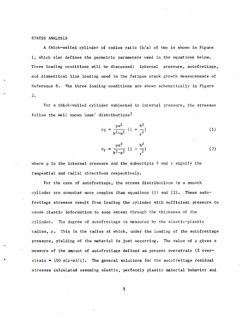
For a thick-walled cylinder subjected to internal pressure, the stresses
follow the well known Lame' distributions^
pa2 b2
ae - .-r-j (i +-) (1) b^-a r
pa2 b2
0t . __ (1 . ..) (a,
where p is the internal pressure and the subscripts 6 and r signify the
tangential and radial directions respectively.
For the case of autofrettage, the stress distributions in a smooth
cylinder are somewhat more complex than equations (1) and (2). These auto-
frettage stresses result from loading the cylinder with sufficient pressure to
cause plastic deformation to some extent through the thickness of the
cylinder. The degree of autofrettage is measured by the elastic-plastic
radius, p. This is the radius at which, under the loading of the autofrettage
pressure, yielding of the material is just occurring. The value of p gives a
measure of the amount of autofrettage defined as percent overstrain (% over-
strain = 100 x(p-a)/t). The general solutions for the autofrettage residual
stresses calculated assuming elastic, perfectly plastic material behavior and

the Tresca yield criteria are:^
f Ooi
b2 p2-b2 p2+b2
-5—j [1 + -rll r- - in -] + [■ b2-a2 r2 2b2 a 2b'
oe v b2 p2 a2 p2-b2
OQU + -7H--7 + -7--7[ 7" " An -]} rz' 2b^ b2-a2 2b
a2 b2 p2-b2 p Oot-r~7 [1 " Til 7" - ^ -] + [
p2+b2
b2-a2 2b/ 2b ^
Jin -] } a < r < p r
p < r < b
Jin -] } a < r < p r
(3)
(4) Or =
b2 p2 a2 p2-b2 p
r2 2b2 b2-a2 2b2 a p < r < b
where 0O is the tensile yield strength. It is important to note that the
autofrettage residual stresses act in the cylinder under no active external
loads. This causes some problems when attempting to determine the effects of
structure discontinuities on autofrettaged cylinders.
Under the diametrical line loading, the stresses can be calculated
exactly only in the form of an Infinite series.24 The solutions for thick
cylinders of radius ratio, W, (W = b/a) ranging from 2 to 10 have been
developed by Rigsperger and Davis.25 For the purpose of this report, the
stress which acts at the OD for a cylinder with W = 2 is given. This stress
acting 90° removed from the load is:
5.88F ae =
TTb (5)
where F is the total force which acts at the OD as shown in Figure 2.
To determine the effects of OD discontinuities on the stresses given
above, accurate numerical techniques must be used which incorporate such

dlscontinuitle*. Three such aethods have been used to do this, a finite
difference asthod, the finite ele««nt msthod, and the boundary collocation
mapping technique. The finite difference approach10 was used to determine
stress intensity factor, K, solutions for thick-walled cylinders of various W
with a single OD crack. The solutions, when compared with K solutions
developed using finite elements8.20 and the collocation method14.16*19 were
inferior. More accurate K solutions were developed using the latter two
methods. Accurate K solutions are necessary when predicting the rate of
growth of stable fatigue cracks and unstable fracture.
To develop K solutions using the finite element method, it is the stress
singularity at the crack tip which causes difficulties. A very large number
of elements is usually required near the crack tip to represent the steep
strain gradient. The recent trend in finite element method is to use high
order isoparametric elements26 so that a high degree of accuracy may be
achieved with a small number of elements. This trend calls for special
elements27.28 which can produce the proper order of singular stresses and
strains at a crack tip. The enriched elements27 that contain Ki and Kn as
additional unknowns are used to model the crack tip region. The approximate
values of K]; and Kn are directly obtained together with nodal displacements.
The collapsed elements,28*29 on the other hand, compute the nodal displace-
ments first. Since a correct order of strain singularity is built in the
special crack tip elements, the displacements obtained are quite accurate.
The stress intensity factors are indirectly calculated from the near field
elasticity solution of displacements in terms of stress Intensity factors.
Both enriched elements and collapsed elements yield comparably accurate K
values.
In the modified boundary collocation^ method, the geometry of the
physical structure is mapped through the use of a complex mapping function to
a simpler geometry in a complex plane. The stress analysis is then performed
in the complex plane and the solution to the physical problem is obtained by
using the same complex mapping function to return to physical space. To use
this method on cylinder problems, the cracked cylinder is first mapped to a
square or rectangular cracked plate." The plate in turn is mapped to a
geometry where the crack is represented by a semicircle. Therefore, two
mappings must be used to obtain the solution. This method was used to
determine K for one to four OD cracks in cylinders which had two W values
loaded with internal pressure.1^ The K solutions for one external crack with
internal pressure loading are shown in Table I.
To use the stress analysis techniques described above, the finite element
model or the mapped geometry must be loaded by active loads. Since the
autofrettage stresses act in the absence of such active external loads, K
solutions were developed using the superposition or the thermal loading
simulation techniques described above. Superposition is more often used with
the mapping collocation method, while the simulation method is more often used
with the finite element methods. The agreement between the collocation^ and
finite element20 solutions was not as good as would have been expected (about
five percent difference). This was attributed to relatively coarse finite
element grid used in Reference 20. The results for a radius ratio of two and
a single external crack for autofrettage loading are shown in Table I.

TABLE I. K SOLUTIONS FOR EXTERNALLY CRACKED THICK-WALLED CYLINDERS
(See Table II for the definition of OOD)
Internal Pressure, 1 Crack
K
:/t
0.167
0.250
0.333
0.417
0.500
0.583
0.667
0.750
0.833
c/t
0.1
0.2
0.3
0.4
0.5
0.6
cJOD/7rc
W=2, FE8
1.341
1.465
1.635
1.883
2.102
2.404
2.753
3.247
3.458
c/t
0.1
0.2
0.3
0.4
0.5
0.6
0.7
W=2, COL14
1.20
1.37
1.56
1.80
2.10
2.49
Autofrettage, 1 Crack
K
OOD^C
W = 2
50% Overstrain
1.129
1.235
1.424
1.647
1.924
2.041
W«3, COL^
1.23
1.37
1.54
1.82
2.12
2.43 '
3.11
100% Overstrain
1.013
0.977
0.969
0.923

To use the numerical solutions given in Table I to predict the rate of
growth of fatigue cracks or fracture, K should be known as a continuous
function of crack length. This can be accomplished by fitting a polynomial to
the numerical K solutions along with limiting solutions.30 The expressions
that were developed for some of the numerical results in Table I have the form
K = OQD /wcU.ia + Ai(c/t) + A2(c/t)2 + A3(c/t)3 + ^(c/t)4)
where ago is the stress which acts at the OD of an uncracked cylinder due to
the applied loading; A^, A2, A3 and A4 are constants; c is crack length; and t
is wall thickness (b-a). The factor 1.12 arises from the fact that as c
approaches zero, K approaches the following:^
K = 1.12 OQD /TTC > (6)
The values of the constants for various loadings are given in Table II
for the cases of internal pressure, diametrical line loading, 50 percent
overstrain and 100 percent overstrain, for a cylinder with W = 2 and a single
external crack. These expressions represent the numerical results within
three percent for any of the loadings considered.
As stated previously, there have been fewer theoretical studies on thick
cylinders which contain OD discontinuities, such as notches, rather than
cracks on the OD. In these studies, the stresses have been calculated by
either estimation^ or with finite elements. ^>^ The most extensive work^
studied the case of a thick cylinder with W = 1.74, subjected to either
internal pressure, 100 percent overstrain or 60 percent overstrain. The
cylinder contained a single OD notch which had a root radius to thickness
ratio (R/t) of 0.013, and a depth to thickness ratio (d/t) of either 0.088 or
10
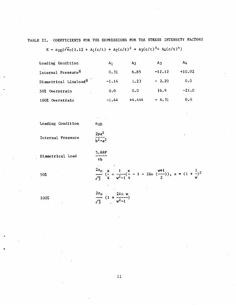
TABLE II. COEFFICIENTS FOR THE EXPRESSIONS FOR THE STRESS INTENSITY FACTORS
K = 000(^(1.12 + A^c/t) + A2(c/t)2 + A3(c/t)3+ A^c/t)4)
Loading Condition Al A2 A3 A4
Internal Pressure8 0.31 6.85 -12.12 +10.02
Diametrical Lineload8 -1.14 1.23 - 2.20 0.0
50% Overstrain 0.0 0.0 16.9 -21.0
100% Overstrain -1.44 +4.444 - 4.31 0.0
Loading Condition a0D
Internal Pressure 2pa2
b^a2
Diametrical Load 5.88F
irb
50% 2ao X 1 X
/3 4 w2-l 4
vrfl 1 , - 1 - 2&n ( )), x = (1 + -)2
2 w
100% 2^0 2£n w — (1 + -r ) /3 , w2-l
11
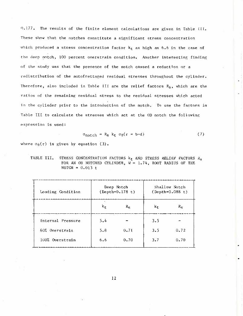
0.177. The results of the finite element calculations are given In Table lit.
These show that the notches constitute a significant stress concentration
which produced a stress concentration factor kj- as high as 6.6 in the case of
the deep notch, 100 percent overstrain condition. Another interesting finding
of the study was that the presence of the notch caused a reduction or a
redistribution of the autofrettaged residual stresses throughout the cylinder.
Therefore, also included in Table III are the relief factors Rg, which are the
ratios of the remaining residual stress to the residual stresses which acted
in the cylinder prior to the Introduction of the notch. To use the factors In
Table III to calculate the stresses which act at the OD notch the following
expression is used:
anotch = Rs kt a60 = b-d) (7)
where OQ(r) is given by equation (3).
TABLE III. STRESS CONCENTRATION FACTORS kt AND STRESS RELIEF FACTORS RQ
FOR AN 0U NOTCHED CYLINDER, W = 1.74, ROOT RADIUS OF THE NOTCH = 0.013 t
Loading Condition
Internal Pressure
60% Overstrain
100% Overstrain
Deep Notch (Depth=0.178 t)
5.4
5.8
6.6
0.71
0.70
Shallow Notch (Depth=0.088 t)
kt
3.5
3.5
3.7
Rg
0.72
0.70
12
PREDICTING THE FAILURE OF CYLINDERS WITH OD DISCONTINUITIES
Using the results from the various stress analyses described above, we
will attempt to predict failure under fatigue conditions. These failures can
occur by either of two mechanisms, fatigue crack, initiation, or fatigue crack
growth. In the case of crack initiation, three factors contribute to failure,
the alternating stress from external loading, tensile mean stress from the
autofrettage stresses, and the stress concentration from the OD discontinuity.
For failure by fatigue crack growth, two factors must be considered, the
alternating K. from the applied loading and the ratio of minimum K (Kmin) t0
maximum K (Kmax)* during fatigue due to changes in autofrettage conditions.
Crack initiation is considered first.
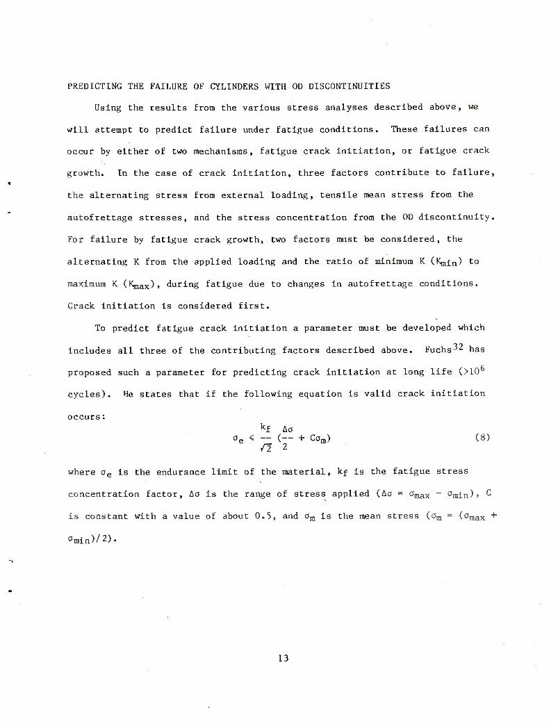
To predict fatigue crack initiation a parameter must be developed which
includes all three of the contributing factors described above. Fuchs^ has
proposed such a parameter for predicting crack initiation at long life (>10
cycles). He states that if the following equation is valid crack initiation
occurs: kf Ao
ae < — (— + Cam) (8) /2 2
where 0e is the endurance limit of the material, kf is the fatigue stress
concentration factor, Aa is the range of stress applied (Ao = 0max - Omin)» ^
is constant with a value of about 0.5, and ara is the mean stress (am = (Omax ■*"
Omin)/2).
13

Extending Fuch's32 work, to short life situations (< 106 cycles), it is
assumed that the value of stress predicted by the right-hand side of equation
(8) is equivalent to the uniaxial alternating stress which results in less
than 10° cycles. The relationship between the stress and life is determined
by the S-N property of the material studied. The S-N behavior of a steel can
be estimated to a first order approximation using the following assumptions.33
At a life of 10 cycles, a specimen in a compression-tension fatigue test will
fail with an alternating stress of
Ao . aa = — = 0.9 auts (@ N - 103 cycles) (9)
where outs ^s the ultimate tensile strength of the material. At a life of 10
cycles, the allowable alternating stress is approximated as
Ao aa = — = 0.5 kakbkc
auts (10) 2
where ka is a factor related to surface finish, k^ is a factor related to the
size of the component considered, and kc is a reliability factor dealing with
statistical considerations. Assuming the steels considered have an ultimate
tensile strength of about 1250 MPa, the cylinders have a machined finish and
are larger than 2 cm, and we desire 99 percent reliability, the respective
values of ka, k^, and kc are 0.65, 0.85, and 0.868. Equation (10) then
becomes
a = — = 0.24 auts ((? N = 10b cycles) (11) 2
It is also assumed that the S-N property of the material falls on the
straight line in log S-log N space which connects the two points defined by
14
■ ■

equations (9) and (11). The solid line in Figure 3 is the estimated S-N
property of the material. The data points in the same figure are actual
measurements of fatigue life from References 8 and 9 using Fuch's criterion
(Equation (8)). The stress concentration factors for the data from Reference
9 are from Reference 17 and are considered to be quite accurate. For the data
from Reference 8, the stress concentration factors were estimated using a
Nuber diagram,3^ and are considered less accurate than those calculated in
Reference 17.
The comparison of the available data with the estimated fatigue life to
crack, initiation suggests that the procedure outlined above is conservative if
the stress concentration factors are known accurately. If the stress
concentration factors must be estimated, the failure prediction gives an
approximate average of failure. In some cases life is underestimated, in
others it is overestimated. To use this method in design warrants the use of
safety factors if kt is not accurately known. The dotted line in Figure 4
shows the failure prediction using a safety factor of two on stress. In this
instance, all of the data fall well beyond the predicted failure curve when kt
is estimated. Using safety factors should only be applied when kt is
estimated, since they may be overly restrictive when kt is accurately known.
To predict failure by fatigue crack growth, a crack growth law which is a
property of the material is needed. The first law developed was the well
known Paris power law-^S
dc -- = Ci AKTO (12) dN
15
where C^ and m are constants, dc/dN is the measured fatigue crack growth rate,
and AK is the range of stress intensity factor applied during loading. This
law is useful in predicting crack growth if K ranges from zero to a positive
value. If K varies from a positive value, I^in. to a maximum value, Kmax, the
crack growth rate may be different from that predicted using equation (12).
This is the case when considering the effect of autofrettage on crack growth."
To model the effects of cycling between two positive Rvalues, several
laws have been suggested. These laws have also incorporated static properties
of the material in their formulation. Either of two static properties,
fracture toughness, Kic, or yield strength, a0 are used. A crack growth law
using Kxc is of the form^"
dc CZAK"1
__ = (13) dN {(l-Rf)KIc - AK}
where C2 and m are constants and Rf is the ratio of minimum K to maximum K
(Rf = Kmin/Kmax)*
An example of a crack growth law incorporating the yield strength of the
material is due to Tabeshfar and Williams:37
dc ^max — = C3( ) (14) dN . a0
where C3 and m are constants.
We used these laws to predict crack growth through the autofrettaged
cylinders reported in Reference 8. The material used in that study was an
AISI 4340 steel with yield strength of about 1140 MPA, and Kic of about 150
MPa/m. The fatigue crack growth property (Equation (12)) has been measured
for this material.38 Using these data the constants in all the crack growth
16
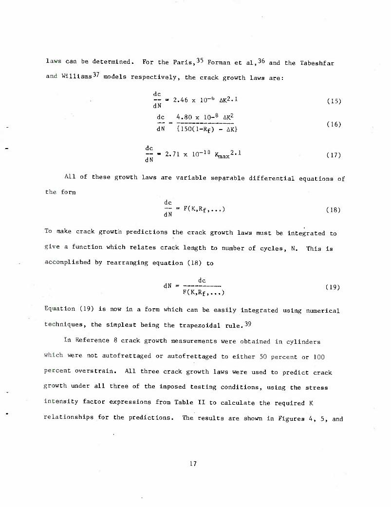
laws can be determined. For the Paris,35 Forman et al,36 and the Tabeshfar
and Williams37 models respectively, the crack growth laws are:
dc — = 2.46 x ICT6 AK2-1 (15) dN
dc 4.80 x 10⁻⁸ AK2
dN {150(l-Rf) - AK} (16)
~ = 2.71 x 10⁻¹⁰ Kraax2.1 (17) dN
All of these growth laws are variable separable differential equations of
the form
dc — = F(K,Rf,...) (18) dN
To make crack growth predictions the crack growth laws must be integrated to
give a function which relates crack length to number of cycles, N. This is
accomplished by rearranging equation (18) to
dc dN = (19)
F(K,Rf,...)
Equation (19) is now in a form which can be easily integrated using numerical
techniques, the simplest being the trapezoidal rule.39
In Reference 8 crack growth measurements were obtained in cylinders
which were not autofrettaged or autofrettaged to either 50 percent or 100
percent overstrain. All three crack growth laws were used to predict crack
growth under all three of the imposed testing conditions, using the stress
intensity factor expressions from Table II to calculate the required K
relationships for the predictions. The results are shown in Figures 4, 5, and
17

6 for the non-autofrettaged, 50 percent overstrain and 100 percent overstrain
conditions respectively.
For the case of no autofrettage, Figure 4, it is clear that all three
crack growth models adequately model the reported crack growth from Reference
8. There is an ordering of the crack growth predictions which shows that
the Paris n»del predicts the slowest crack growth, the Tabeshfar and Williams
the fastest and the Forman et al falling in between giving the best approxima-
tion to the actual behavior. This suggests that there is an effect of Rf
ratio even in the case of no autofrettage when one would consider the Paris
law to provide the best prediction. In the experiments reported in Reference
8, Rf was 0.1, while the crack growth data from Reference 7 was developed with
Rf = 0.
In examining the results in autofrettage cylinders. Figures 5 and 6, we
find that no model gives an accurate estimate of fatigue crack growth. The
poorest correlation occurs in the case of 100 percent overstrain, where the
Tabeshfar and Williams model predicts the crack should grow to a length of
about 9.5 mm in less than 2,500 cycles when it actually required about 50,000
cycles to obtain that depth. To explain this difference it should be noted
that in the initial crack growth regions, the Paris model gives a relatively
good approximation for the crack growth behavior. At greater crack depths,
the Paris prediction substantially overestimates the cycles required to grow
the crack further. Although the Forman et al, and Tabeshfar and Williams
models underestimate the crack growth behavior initially, the cycles required
to cause additional crack growth are reasonably approximated. For example
consider the 50 percent overstrain case. Figure 5. To grow a crack from 4 mm
18

to about 7.5 mm requires about 15,000 cycles according to Forman et al. In
the data from Reference 8 for the same range of crack growth, 25,000 to 30,000
cycles were actually needed. These observations suggest that near the starter
notch used to initiate the fatigue cracks, a model assuming no autofrettage
applies, while removed from the starter notch, a model which incorporates a
significant contribution from autofrettage seems to give a reasonable estimate
of life. This indicates that the presence of the notch may significantly
change the residual stresses near the notch. Removed from the notch, there
seems to be little effect on the residual stress due to the notch; the crack
growth model of Forman et al gives a reasonable estimate of crack growth.
CONCLUSIONS
Much work, mostly theoretical stress analyses, has been performed to
study the effects of QD initiated failures in thick-walled cylinders. The
stress analyses were developed using very accurate numerical techniques which
have the potential for being very useful in the design of thick-walled
pressure vessels. At this time there seems to be insufficient experimental
results to use the theoretical studies to predict the OD initiated failure of
these vessels with any great accuracy. Using the analytical results and
estimated fatigue crack initiation properties, conservative estimates of
fatigue life can be made which may be useful to prepare cylinder designs which
should not fail by fatigue crack initiation. Also, if failure occurs by
fatigue crack growth, conservative estimates of fatigue life may be obtained
using available crack growth models. Neither of the two models which account
for the mean stress affect on fatigue crack growth agreed very well with the
19
observed data. The use of the model by Forman et al^ did give the best
estimate of the maximum fatigue crack growth rates and should give a
conservative estimate of fatigue life. More work is needed to develop the
technology necessary to estimate fatigue failure with greater accuracy.
20

REFERENCES
1. Davidson, T. E. and Kendall, D. P., The Mechanical Behavior of Materials
Under Pressure, H.L.I.D. Pugh, Ed., Elsevier Publishing, Amsterdam, 1970.
2. Harvey, John F., Theory and Design of Modern Pressure Vessels, 2nd Ed.,
Van Nostrand Reinhold Co., New York, 1974, p. 59.
3. Davidson, T. E., Eisenstadt, R., and Reiner, A. N., ASME Journal of Basic
Engineering, December 1963, p. 555.
4. Davidson, T. E., Barton, C. S., Reiner, A. N. and Kendall, D. P., in
Proceedings of the First International Congress on Experimental Mechanics,
Pergamon Press, Oxford, 1963.
5. Brown, Bruce B., "Fatigue Test, 155 MM M199 Barrel," AilRADCOM Technical
Report ARLCB-TR-80034, Benet Weapons Laboratory, Watervliet, NY, December
1980.
6. Brown, Bruce B. and McAlonie, Howard D., "Safe Service Life Testing of the
155 MM M185 Howitzer Barrel With M203 Propelling Charge," ARRADCOM
Technical Report ARLCB-TR-81032, Benet Weapons Laboratory, Watervliet, NY,
August 1981.
7. Brown, Bruce B. and McAlonie, Howard D., "Fatigue Performance Comparison
of Rotary Forged and Conventionally Forged Cannon Barrels (105 MM M68),"
ARRADCOM Technical Report ARLCB-TR-81037, Benet Weapons Laboratory,
Watervliet, NY September 1981.
8. Kapp, J. A. and Eisenstadt, R., in Fracture Mechanics, Smith, C. W., Ed.,
ASTM STP 677, American Society of Testing and Materials, Philadelphia, PA,
1979, p. 746.
21

9. Kapp, J. A. and Underwood, J. H., Proceedings of the Third International
Congress on Experimental Mechanics, Society for Experimental Stress
Analysis, Brookfield Center, CT, 1981.
10. Emery, A. F. and Segedln, C. M., Journal of Basic Engineering, June 1972,
p. 387.
11. Chapra, P. S., Nuclear Engineering Design, Vol. 29, 1974, p. 7.
12. Kobayashl, A. S., Polvanlch, N., Emery, A. F., and Love, W. J. , Journal
of Pressure Vessel Technology, February 1977, p. 83.
13. Hussaln, M. A. and Pu, S. L., "Preliminary Study of the Effect of a
Recoil Keyway on the Fatigue Life of the M185 Cannon Tube," ARRADCOM
Technical Report ARLCB-TR-78017, Benet Weapons Laboratory, Watervliet,
NY, 1978.
14. Tracy, P. G., Engineering Fracture Mechanics, Vol. 11, 1979, p. 291.
15. Cesarl, Francesco, and Hellen, T. K. , International Journal of Pressure
Vessels and Piping, Vol. 7, 1979, p. 199.
16. Parker, A. P. and Andraslc, C. P., "Stress Intensity Prediction for a
Multiply-Cracked, Pressurized Gun Tube With Residual and Thermal
Stresses," presented at the Army Symposium on Solid Mechanics, 1980.
17. Kapp, J. A. and Pflegl, G. A., Journal of Pressure Vessel Technology,
Vol. 103, February 1981, p. 78.
18. Pu, S. L. and Hussaln, M. A., Journal of Pressure Vessel Technology, Vol.
103, May 1981, p. 301.
19. Parker, A. P., "Stress Intensity and Fatigue Crack Growth in Multiply-
Cracked, Pressurized Partially Autofrettaged Thick Cylinders," AMMRC
Technical Report TR81-37, 1981.
22
20. Pu, S. L,, "Stress Intensity Factors for Radial Cracks at Outer Surface
of a Partially Autofrettaged Cylinder Subjected to Internal Pressure,"
ARRADCOM Technical Report ARLCB-TR-82002, Benet Weapons Laboratory,
Watervliet, NY, 1982.
21. Underwood, J. H. and Kendall, D. P., Developments in Fracture Mechanics
Test Methods, ASTM STP 632, 1977, p. 25.
22. Parker, A. P. and Farrow, J. R., Journal of Strain Analysis, Vol. 15, No,
1, 1980, p. 51.
23. Hussain, M. A., Pu, S. L., Vasilakis, J. D., and O'Hara, G. P., Journal
of Pressure Vessel Technology, Vol. 102, No. 3, 1980, p. 314.
24. Timoshenko, S. P. and Goodier, J. N., Theory of Elasticity, 3rd Ed.,
McGraw-Hill, NY, 1970, p. 136.
25. Rigsperger, E. A. and Davis, N., Trans. ASCE, Vol. 112, 1947, p. 619.
26. Gifford, I. N., Jr., "APES-Second Generation Two-Dimensional Fracture
Mechanics and Stress Analysis by Finite Elements," Report 4799, Naval
Ship Research and Development Center, 1975.
27. Gifford, I. N., Jr. and Hilton, P. D., "Stress Intensity Factors by
Enriched Finite Elements," Engineering Fracture Mechanics, Vol. 10, No.
3, 1978, pp. 485-496.
28. Barsoum, R. S., International J. for Numerical Methods in Engineering,
Vol. 10, 1976, p. 25.
29. Pu, S. L., Hussain, M. A., and Lorensen, W. E., "The Collapsed Cubic
Isoparametric Element as a Singular Element for Crack Problems," Int. J.
for Numerical Methods in Engineering, Vol. 12, 1978, pp. 1727-1742.
23
30. Kapp, J. A., Newman, J. C., Jr., and Underwood, J. H., Journal of Testing
and Evaluation. Vol. 8, No. 6, November 1980, p. 314.
31. Tada, H., Paris, P. C, and Irwln, G. R., The Stress Analysis of Cracks
Handbook, Del Research Corp., Hellertown, PA, 1973.
32. Fuchs, H. D., J. of Basic Engineering, Series D, Vol. 87, 1965, p. 333.
33. Shlgley, Joseph Edward, Mechanical Engineering Design, McGraw-Hill, NY,
1972, p. 245.
34. Ugural, A. C. and Feuster, S. K. , Advanced Strength and Applied
Elasticity, American Elsevier Publishing Co., NY, 1975, p. 83.
35. Paris, P. and Erdogan, F. J., J. of Basic Engineering, Vol. 85, Series D,
1963, p. 5280.
36. Forman, R. G., Kearney, V. E. and Engle, R. M., J. of Basic Engineering,
Vol. 89, Series D, 1967, p. 459.
37. Tabeshfar, K. and Williams, T. R. G., J. of Sound and Vibration, Vol. 68,
No. 2, 1980, p. 295.
38. Damage Tolerant Design Handbook, Part 2, Metals and Ceramics Information
Center, Battelle, Columbus, OH, January 1975.
39. Carnahaw, Bruce, Luther, H. A., and Wilkes, James 0., Applied Numerical
Methods, John Wiley & Sons, Inc., New York, 1969, p. 73.
24

Figure 1. A Thick-Walled Cylinder Containing Various OD Discontinuities,
25
Inttrnal Pressure
Autofrettagt
Diametrical Line Loading
Figure 2. The Three Loading Conditions Considered.
26

0) 3 M
•H P
(0 o
the Estimated
on Criteria.32
IO T3 -H
o (3 -M
^-^ •H
Z. 0 fj
"'* ■H C J 1—l
0) v.
00 03 -^ ■H U o ■M U
u. 03 U. if)
o o ♦-
T3 "jd
tmtm h 3 W) 3 tu 0) w
03 C
ison of Me
xpanding o
tn n3 O QH <U
B <* O -H U i-J
to
CD
M 3 CO
•H
OooloT cvT -:
•»ns/b,s
27
"3 (D h
o ■p <u in u
^_
C nS
■p S G
XJ c
• H rH
u cd
c 4-1
w —1 a>
O
(/) r. 1/1
o o _J U
3 o
■H CJ o fH • >- =1 ^ ai
o W)> tn o ■H
4-) M _l rt C ■M
it u. LO
^-~' XI 3 rH
z. X 2 3 -t-1 -d w S •H rj o tfl o h (D 2 CJ a; ■+- ^ o o 2
8 C h M o u C
•H •H o c
o 14 CO
•H
't a •H ■t->
s ♦J C o rt o
o u u. u
8 CD
28
J
D D
U D 3 a -
D D
a D —
D O ^
D D ^^ -
D D ^^^
DO ^EQ 15
EQ 16
—
1 1 1 □ REF 8
40 60 60
N (kilocyclts)
Figure 5. Comparison of Measured Fatigue Crack Growth and Predicted Fatigue Crack Growth Using Various Models for a Cylinder Containing 50 Percent Overstrain Residual Stresses.
29
4-1 0) o -a
•H C — .^ t) r^ M >. .
DH u C/l in
x; n$ o c h 73 U ♦J
0 ■/;
-1= '4- +J i—i
S 1/) rt 0 I—1 3 h o "0 u X) •H
0 l/l M " (U CJ PS rt t/i fH ~ i=
! I 0 • H ■rH cd
CJ fH Vi 3 - •M D0> in
•rH ^ •P M OJ td c > u, .H
1/1 o
nfl 3 ■p IU c h ,C o 3 ■P o w S )H rt 0 o u h o- S U
o 4-1 ^ o o ^H
C 'M M o LJ c -/■) ■H •H 5; PS (H 3 •rH 03 b( Cli & ■H P i ■I-' c 0 rt 0 U u- LJ
'C
Ci SH
3 oi
'—
30

TECHNICAL REPORT INTERNAL DISTRIBUTION LIST
NO. OF COPIES
CHIEF, DEVELOPMENT ENGINEERING BRANCH 1 ATTN: DRDAR-LCB-DP 1
-DR 1 -DS (SYSTEMS) 1 -DS (ICAS GROUP) 1 -DC 1
CHIEF, ENGINEERING SUPPORT BRANCH 1 ATTN: DRDAR-LCB-SE 1
CHIEF, RESEARCH BRANCH 2 ATTN: DRDAR-LCB-R (ELLEN FOGARTY) 1
-RA 1 -RM 1 -RP 1 -RT 1
TECHNICAL LIBRARY 5 ATTN: DRDAR-LCB-TL
TECHNICAL PUBLICATIONS & EDITING UNIT 2 ATTN: DRDAR-LCB-TL
DIRECTOR, OPERATIONS DIRECTORATE 1
DIRECTOR, PROCUREMENT DIRECTORATE 1
DIRECTOR, PRODUCT ASSURANCE DIRECTORATE 1
NOTE: PLEASE NOTIFY DIRECTOR, BENET WEAPONS LABORATORY, ATTN: DRDAR-LCB-TL, OF ANY REQUIRED CHANGES.

TECHNICAL REPORT EXTERNAL DISTRIBUTION LIST
NO. OF COPIES
NO. OF COPIES
ASST SEC OF THE ARMY RESEARCH 5 DEVELOPMENT ATTN: DEP FOR SCI d, TECH 1 THE PENTAGON WASHINGTON, D.C. 20315
COMMANDER DEFENSE TECHNICAL INFO CENTER ATTN: DTIC-DDA 12 CAMERON STATION ALEXANDRIA, VA 22314
COMMANDER US ARMY MAT DEV § READ COMD ATTN: DRCDE-SG 1 5001 EISENHOWER AVE ALEXANDRIA, VA 22333
COMMANDER US ARMY ARRADCOM ATTN: DRDAR-LC 1
DRDAR-LCA (PLASTICS TECH 1 EVAL CEN)
DRDAR-LCE 1 DRDAR-LCM [BLDG 321) 1 DRDAR-LCS 1 DRDAR-LCU 1 DRDAR-LCW 1 DRDAR-TSS (STINFO) 2
DOVER, NJ 07801
DIRECTOR US ARMY BALLISTIC RESEARCH LABORATORY ATTN: DRDAR-TSB-S (STINFO) " 1 ABERDEEN PROVING GROUND, MD 21005
COMMANDER US ARMY ARRCOM ATTN: DRSAR-LEP-L 1 ROCK ISLAND ARSENAL ROCK ISLAND, IL 61299
COMMANDER ROCK ISLAND ARSENAL ATTN: SARRI-ENM (MAT SCI DIV) ROCK ISLAND, IL 61299
DIRECTOR US ARMY INDUSTRIAL BASE ENG ACT ATTN: DRXIB-M ROCK ISLAND, IL 61299
COMMANDER US ARMY TANK-AUTMV R5D COMD ATTN: TECH LIB - DRSTA-TSL WARREN, MICHIGAN 48090
COMMANDER US ARMY TANK-AUTMV COMD ATTN: DRSTA-RC WARREN, MICHIGAN 48090 '
COMMANDER US MILITARY ACADEMY ATTN: CHMN, MECH ENGR DEPT WEST POINT, NY 10996
US ARMY MISSILE COMD REDSTONE SCIENTIFIC INFO CEN ATTN: DOCUMENTS SECT, BLDG 4484 REDSTONE ARSENAL, AL 35898
COMMANDER US ARMY FGN SCIENCE ATTN: DRXST-SD 220 7TH STREET, N.E CHARLOTTESVILLE, VA
§ TECH CEN
22901
COMMANDER US ARMY MATERIALS 5 MECHANICS
RESEARCH CENTER ATTN: TECH LIB - DRXMR-PL WATERTOWN, MASS 02172
NOTE: PLEASE NOTIFY COMMANDER, ARRADCOM, ATTN: BENET WEAPONS LABORATORY, DRDAR-LCB-TL, WATERVLIET ARSENAL, WATERVLIET, N.Y. 12189, OF ANY REQUIRED CHANGES.

TECHNICAL REPORT EXTERNAL DISTRIBUTION LIST (CONT.)
NO, OF COPIES
NO. OF COPIES
COMMANDER US ARMY RESEARCH OFFICE ATTN: CHIEF, IPO P.O. BOX 12211 RESEARCH TRIANGLE PARK, NC
COMMANDER US ARMY HARRY DIAMOND LAB ATTN: TECH LIB 2800 POWDER MILL ROAD ADELPHIA, MD 20783
COMMANDER NAVAL SURFACE WEAPONS CEN ATTN: TECHNICAL LIBRARY
CODE X212 DAHLGREN, VA 22448
27709
DIRECTOR US NAVAL RESEARCH LAB ATTN: DIR, MECH DIV
CODE 26-27 (DOC LIB) WASHINGTON, D.C. 20375
METALS S CERAMICS INFO CEN BATTELLE COLUMBUS LAB 505 KING AVE COLUMBUS, OHIO 43201
MATERIEL SYSTEMS ANALYSIS ACTV ATTN: DRSXY-MP ABERDEEN PROVING GROUND MARYLAND 21005
NOTE: PLEASE NOTIFY COMMANDER, ARRADCOM, ATTN: BENET WEAPONS LABORATORY, DRDAR-LCB-TL, WATERVLIET ARSENAL, WATERVLIET, N.Y. 12189, OF ANY REQUIRED CHANGES.


