International Journal of Current Engineering and Technology E-ISSN 2277 – 4106, P-ISSN 2347 – 5161 ©2017 INPRESSCO®, All Rights Reserved Available at http://inpressco.com/category/ijcet
Research Article
872| International Journal of Current Engineering and Technology, Vol.7, No.3 (June 2017)
Fabrication of a Prototype of Telescopic Boom Radial Ship Loader (TBRSL)
K Sai Venkat Ram†*, B. Poulu†, D Naren Sai† and P. Krishna Kumar†
†Department of Mechanical Engineering, VidyaJyothi Institute of Technology, Hyderabad, T.S., India Accepted 01 May 2017, Available online 02 May 2017, Vol.7, No.3 (June 2017)
Abstract Loading of bulk material like iron ore, coal, fertilizer, grains into ships for transportation by sea is done by ship loaders. Ship loaders are very common sight in ports and jetties from where bulk materials are exported. It mainly consists of an extendable boom, a belt conveyor and a mobile structure to support the boom. It usually mounted on rails and sometimes on tires and can move in order to be able to reach the whole length of the ship and also equipped with a boom which can move up and down so that it can fill all the corners of the ship hatches. Ship loaders are built in capacities from 10 to 15000 TPH (tones per hour). Keywords: The author can include 5-7 words like Thermal Analysis, Pre-conditioner, In-mold, Inoculant’s efficiency. 1. Introduction
1 The ship loader of arc track type of cement and clinker is the efficient and continuous device. It is widely used in the industry of cement, grain, freestone and coal. The front-end trestle track of the ship loader of arc type is in the shape of arc. The distance between the centre of turret vehicle of the ship loader and the centre of the rear-end pier stud of the ship loader does not change and the materials are shipped through the belt machine in the swing shipment cantilever. The length of frontage and the length of apron belt needed by the ship loader is obviously reduced in contrast with the ship loader of the movable type, so the construction cost of the dock can be saved, the adaptability of the ship type is better than ship loader of movable type and the efficiency of the shipment is high, therefore, it is adopted in the large coal or ore terminal. The ship loader of arc track type of cement and clinker is composed of the flexible sliding tube system, cantilever crane system, portal, flexible structure of cantilever crane, belt machine system, cart running system, rear rotating bearing system, wind proofing anchoring, cab, electrical, equipment room, electrical system, plat form walk way and ladder, dust collection devices and other parts (M.J. Hadianfard, et al, 2007). Arc type of ship loaders are usually mounted on a pair of rails are parallel to the berth of the ship. This type of ship loader can perform operations like long travel, luffing and slewing movement of the boom but cannot load material to all portions of the ship hatches and also requires huge berth construction work and *Corresponding author: K Sai Venkat Ram
more number of conveyors. A linear ship loader is usually mounted on a pair of rails that are parallel to the berth and the ship. This type of ship loader can perform operations like long travel, luffing and telescopic movement of the boom to reach all portions of the ship hatch (A. Nazari, et al, 2007)
2. Working theory
When the belt machine of the rear feeding is aiming at the ship loader, the feeding will be offered from the feeding point of the slewing bearing centre. The material will be transmitted on the belt machine through the ship loaded can be finished through the single or combined actions of the cart running and cantilever flexibility to reach the goal of loading the ship. Additionally the actions of the flexible sliding tube structure is applicable to the changes of the different water lever and the height of the materials of the ship loaded (G. Buyukozkan, et al , 2008). The track mobile ship loader can be divides into powder ship loader and bulk cargo ship loader. The powder ship loader is mainly for loading powder materials such as bulk cement, fly ash and bulk cargo ship loader for loading cement clinker, loading materials of mixture of block, particle and powder. The vertical moving uses the manual or electrical winch on the ship. The comprehensive displacement of both can move position in many positions of feed part and arrange materials in the whole range of cabin. The track mobile ship loader is fit for small size barges under 500t. Both common open cabin barges can charge in a convenient way. The capacity for charging generally is around 300t per hour.The track mobile

K Sai Venkat Ram et al Fabrication of a Prototype of Telescopic Boom Radial Ship Loader (TBRSL)
873| International Journal of Current Engineering and Technology, Vol.7, No.3 (June 2017)
ship loader and transport ship are arranged in a vertical way. The tonnage of charging ship is decided by moving and stretching distance of the ship loader. When it is requires to charge large ship size, there shall have larger space for retreating. So the characteristics of the ship loader are large depth in vertical direction while small in horizontal direction without affecting the work of the other devices on the dock. The top in bulk of the ship loader can move back totally to quayside before and after charging work. Therefore, there is no interference effect between driving platform and mast of the ship. For large-scale carrying vertical direction, so ships shall be moved in a vertical direction. This will inevitably occupy two berths, and it is not economic to use of quay berth and difficult to move in a vertical direction for large-scale vessels. So it is required to consider the feasibility of design scheme synthetically from many aspects.
Figure 1 Radial Ship Loader
3. Development and History Tele stack has announced the successful installation of
a fully customized mobile ship loader for the unloading
of grain to coaster vessels at lsle of weight grain’s
median wharf facility. The LDU 521 grain loader, which
has already loaded 10,000 tonne to vessels since its
installation in April, is part of a significant investment
for the grain storage co-operative to ensure that they
meet there target of 30,000 tonne of grain exported per
year to main-land Europe.
Isle of weight grain which handles 90 percent of
arable crops grown on the island, has seen volumes
more than double in the past two decades. Tele stack
cambered boom ship loader, which is being fed directly
from the grain hatch of trucks onto 4000 tonne coaster
vessels, includes an integrated variable speed drive
and heavy duty lattice frame.
The design also facilitates the integration of a 360
degree trimming chute, for increased trimming
capabilities if required.
Last year, Isle of weight grain agreed a new 20-year
lease with the port operator and logistics firm PD ports
giving them a more secure tenure and the confidence
to invest again on the Island.
4. Importance of TBRSL
Radial and telescopic features offer unrivaled
trimming capabilities for most sized vessels.
Mobility means flexibility – complete on-site
mobility including driven wheels, tracks, rails and
a combination to suit complete range of Jetty /
quayside designs.
Complete dust extraction/ suppression options for
handling complete of materials.
Fully sealed feed-in/ transfer and discharge points to eliminate spillage on site.
Loading rates up to 3,000 TPH. Fully extended lengths up to58 meters (190ft) Typically lower capital investment than fixed ship
loading systems. Lead times can range from 10-30 weeks. Reduced civil requirements on site. Land/sea based systems are available. Eliminate double handling of material in
port/Inland terminal.
5. Applications
Mobile ship loaders/ Un loaders designed for
loading Barges, coasters, handy size, handy max,
panama vessels.
Complete mobility for use in differing sized ports
and loading complete range of vessels
Ability to handle complete range of materials such
as coal, grains, fertilizers, ore’s(iron, copper, gold,
bauxite), aggregates, woodchips, wood pellets,
sulphur, cement clinker etc can be easily fed from
fixed conveyor systems, wheel loaders, trucks,
overhead conveyors, tripper conveyors and many
other systems.
6. Key Features of TBRSL
Mobility – Driven wheels(In-line, parallel, radial
modes), track mounted(harsh ground conditions), wheels and rail mounted
Dust suppression measures – Galvanised / canvas Dust covers, telescopic dust covers, dust extraction, integrated telescopic chutes (free-fall cascade design). 360 degree trimmer chutes, Rubber ‘sock’ chutes, water suppression and many more.
Marine specification paint finish.

K Sai Venkat Ram et al Fabrication of a Prototype of Telescopic Boom Radial Ship Loader (TBRSL)
874| International Journal of Current Engineering and Technology, Vol.7, No.3 (June 2017)
6.1 Fabrication of a prototype of TBRSL
Figure 2 General arrangement of prototype radial ship loader
Figure 3 Front and side view of radial ship loader:
6.1.1 Material used G.I Sheet The galvanized iron (GI) sheets are produced as plain coils and corrugated sheets. Corrugated sheets are also known as GI sheets. These are value added steel products which are tough, sturdy, light weight, bridge, corrosion resistant and easy to transport.
Figure 4 G I Sheet
G I sheet properties
To retain the steel intact with its full initial strength.
To provide the surface a more pleasing appearance.
To increase the life of any suitable organic finishing system applied over it.
To protect the steel from corrosive attack in most atmosphere, acting as a continuous and lasting shield between steel and the atmosphere
6.2 Conveyors
Screw conveyor A screw conveyor is a mechanism that uses a rotating helical screw blade, called a “flighting”, usually within a tube, to move liquid or granular materials. They are used in many bulk handling industries. Screw conveyors in modern industry are often used horizontally or at a slight incline as an efficient way to move semi-solid materials, including food waste, wood chips, aggregates, cereal grains, animal feed, boiler ash, meat and bone meal, multiple solid waste and many others. The first type of screw conveyers used since ancient times to pump irrigation water.
Figure 5 Mechanism of screw conveyor
Belt conveyors One of the basic tool in material handling industry, belt conveyors are most commonly used in transportation of bulk materials (grain, salt, coal, ore, sand etc). Belt conveyor system consists of two or more pulleys and end-less loop of carries forward, one or both pulleys are powered. The powered pulley is called “drive pulley” the unpowered one is known as idler pulley. Belt conveyor is general material handling such as those moving boxes along inside a facility from a different class of belt conveyor from those are used to

K Sai Venkat Ram et al Fabrication of a Prototype of Telescopic Boom Radial Ship Loader (TBRSL)
875| International Journal of Current Engineering and Technology, Vol.7, No.3 (June 2017)
transport large volumes of resource and agricultural materials.Based on those that are used to transport large volumes of resources and agricultural
Figure 6 Bending of long conveyor
Figure 7 working of conveyor Conveyors are the transportation means for moving of materials from one place to another. Carrying, return idlers are utilized for movement of belt. Idlers are made of wood. 6.3 Pulleys A pulley is a wheel on an axle or shaft that is designed to support movement and change of direction of a taut cable, supporting shell is referred to as a “block”. A pulley may also be called a sheave or drum and may have a groove or grooves between two flanges around its circumference. The drive element of a pulley system can be a rope, cable, belt, or chain that runs over the pulley inside the groove of grooves (Y. M. Wang, et al, 2006). Hero of Alexandria identified the pulley as one six simple machines used to lift weights, pulleys are assembled to form a block and tackle in order to provide mechanical advantage to apply large forces. Pulleys are also assembled as part of belt and chain drives in order to transmit power from one rotating shaft to another.
Figure 8 Rotating shaft of a pulley
Head pulley
The pulley at the discharge end of the conveyor belt; may be either an idler or a drive pulley. Usually it has a larger diameter than other pulleys in the system and is often lagged to increase traction and pulley life. (Y. M. Wang, et al,1985).
Figure 9 Head pulley
Snub pulley
Mounted close to the drive pulley on the return side of the belt, the snub pulley's primary job is to increase the angle of wrap around the drive pulley, thereby increasing traction. Its secondary purpose is reducing belt tension, which is important in maximizing conveyor component life. Maybe lagged for longer wear life (L. Mikhailov, et al,1996).
Figure 10 snub pulley 6.4 Tracks For tracks, the making of length-900mm, beadth-
45mm is marked on G.I. Sheet as shown in the above figure.
The marked part separated by cutting according to the marking marked on the sheet.
The machined part is bending in such a way that it appears in “Z”- shape with length of 10mm of breadth down wads at one end and length of 15mm of breadth upward at another end.
The final obtained part is appeared as shown in below figure.
Figure 11 bending of the tracks
K Sai Venkat Ram et al Fabrication of a Prototype of Telescopic Boom Radial Ship Loader (TBRSL)
876| International Journal of Current Engineering and Technology, Vol.7, No.3 (June 2017)
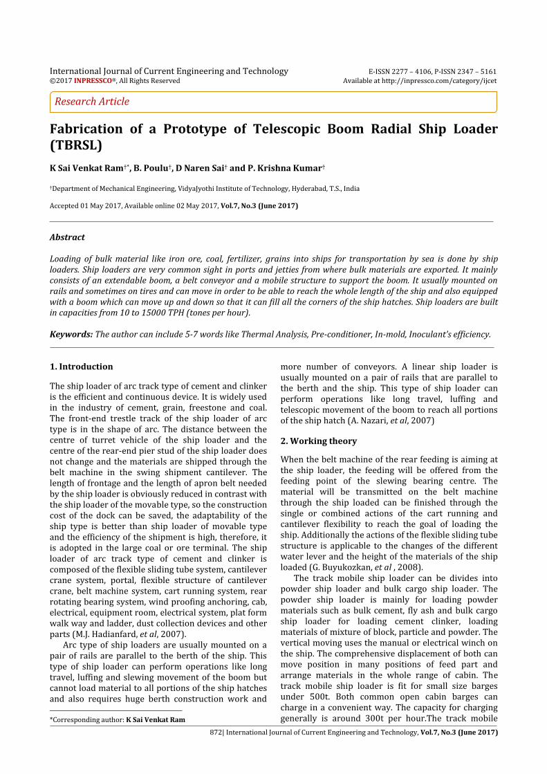
6.5 Telescopic boom
The markings of length-200mm, breadth-215mm
is done on G.I. sheet as shown in above figure. Cutting is done as per markings marked. The machined part is bended at the length of
70mm on either side towards on direction. The final part is appeared as shown in below
figure.
Figure 12 shuttle boom
6.6 Arc wheel support The markings of length-140mm and breadth-
233mm are marked on G.I. sheet as shown in above figure.
Cutting operation is performed for marked taking markings as reference.
Bending operation is done along breadth-233mm at the height of 83mm on either side.
A hole of 13mm dia is drilled on one side of bended sheet for fixing of 10rpm geared motor.
3mm dia hole is drilled on remaining sides for fixing wheels.
The final part is appeared as shown in below figure.
Figure13 Arc wheel support
6.7 Bearing plates Initially, the markings of length-70mm, breadth-
60mm and thickness-3mm are marked on a mild steel sheet as shown in above figure.
The marked markings are taken as reference and cutting is done.
Machined part is cleanly grinded or filed to terminated the irregularities that are formed while machining.
3mm dia is drilled at each corners of the piece at the height and length of 10mm respectively as shown in previous figure.
The number of pieces to be made is two. A hollow shaft of 15mm dia is cutted at the height
of 15mm for bearing. Machined hollow shaft is welded to one of the
plate, which is fixed to the base for bridge conveyor support.
The final part is obtained as shown in below
figure
Figure 14 Finished bearing plate
6.8 Luffing arrangement For luffing arrangement, we need ‘4’ flats of length-
190mm, breadth-17mm and thickness-3mm as shown in above figure.
Two flat are welded in such a way that they should appear as ‘V’ shape and the distance between two free ends should be 80mm.
Two ‘V’ shape flats are welded with another four flats with same dimensions mentioned above.
The final part is obtained as shown in below figure.
Figure 15 Front view of luffing arrangement

K Sai Venkat Ram et al Fabrication of a Prototype of Telescopic Boom Radial Ship Loader (TBRSL)
877| International Journal of Current Engineering and Technology, Vol.7, No.3 (June 2017)
Luffing material
Figure 16 Finished part of luffing material Luffing motor casing
Markings of length-70mm, breadth-50mm are
marked on G.I. sheet as shown in above figure.
The marked part is cutted as per markings.
At one end of the length, bending operation is
done at a height of 10mm. so that; it looks like
‘L’ shape in side view.
Taking a center on 60*50 sides, a hole of
13mm dia is drilled for motor.
The final part is obtained as shown in below
figure.
We are using motors for low speed up to 10 rpm dc geared motors.
Figure 17 motors with 10 rpm DC supply
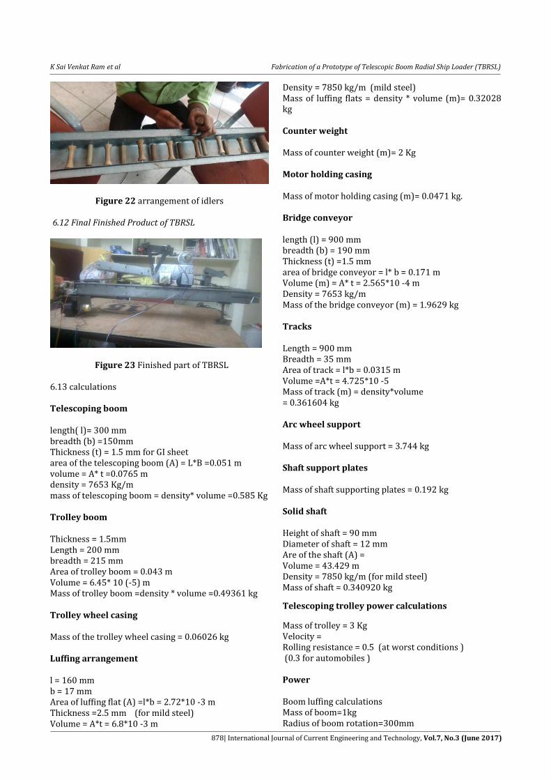
6.9 Idlers System used to transmit the rotation of the main shaft of a motor to another rotating device. Carrying Idlers
Carrying rollers are used to support the conveyor belt and are installed on the groove shape frame, Groove shape forward inclined idler frame and transition idler frames. Rollers include high quality bearing, multi-labyrinth sealing, greased and sealed for life and critical specifications essential for high performance.
Figure 18 carrying idlers
Returning idlers
They are fixed right below the carrying idlers and they helps the belt to move in backward or returning movement.
Figure 19 Returning idlers
6.10 Assembly process of tracks, bridge conveyor, arc wheel support and support column
Figure 20 2D view of arc wheel support Pulleys and Idlers arrangement
Figure 21 pulleys and idlers
K Sai Venkat Ram et al Fabrication of a Prototype of Telescopic Boom Radial Ship Loader (TBRSL)
878| International Journal of Current Engineering and Technology, Vol.7, No.3 (June 2017)
Figure 22 arrangement of idlers 6.12 Final Finished Product of TBRSL
Figure 23 Finished part of TBRSL 6.13 calculations Telescoping boom length( l)= 300 mm breadth (b) =150mm Thickness (t) = 1.5 mm for GI sheet area of the telescoping boom (A) = L*B =0.051 m volume = A* t =0.0765 m density = 7653 Kg/m mass of telescoping boom = density* volume =0.585 Kg Trolley boom Thickness = 1.5mm Length = 200 mm breadth = 215 mm Area of trolley boom = 0.043 m Volume = 6.45* 10 (-5) m Mass of trolley boom =density * volume =0.49361 kg Trolley wheel casing Mass of the trolley wheel casing = 0.06026 kg Luffing arrangement l = 160 mm b = 17 mm Area of luffing flat (A) =l*b = 2.72*10 -3 m Thickness =2.5 mm (for mild steel) Volume = A*t = 6.8*10 -3 m
Density = 7850 kg/m (mild steel) Mass of luffing flats = density * volume (m)= 0.32028 kg Counter weight Mass of counter weight (m)= 2 Kg Motor holding casing Mass of motor holding casing (m)= 0.0471 kg. Bridge conveyor length (l) = 900 mm breadth (b) = 190 mm Thickness (t) =1.5 mm area of bridge conveyor = l* b = 0.171 m Volume (m) = A* t = 2.565*10 -4 m Density = 7653 kg/m Mass of the bridge conveyor (m) = 1.9629 kg Tracks Length = 900 mm Breadth = 35 mm Area of track = l*b = 0.0315 m Volume =A*t = 4.725*10 -5 Mass of track (m) = density*volume = 0.361604 kg Arc wheel support Mass of arc wheel support = 3.744 kg Shaft support plates Mass of shaft supporting plates = 0.192 kg Solid shaft Height of shaft = 90 mm Diameter of shaft = 12 mm Are of the shaft (A) = Volume = 43.429 m Density = 7850 kg/m (for mild steel) Mass of shaft = 0.340920 kg
Telescoping trolley power calculations
Mass of trolley = 3 Kg Velocity = Rolling resistance = 0.5 (at worst conditions ) (0.3 for automobiles ) Power Boom luffing calculations Mass of boom=1kg Radius of boom rotation=300mm
K Sai Venkat Ram et al Fabrication of a Prototype of Telescopic Boom Radial Ship Loader (TBRSL)
879| International Journal of Current Engineering and Technology, Vol.7, No.3 (June 2017)
Force= m*g=1*9.81=9.81Newton Torque=F*R=9.81*0.3=2.943 N-m Power=3.081 watts Conveyor calculations Mass of carrying idlers=11*40=440gms Mass of return idlers=8*30=240gms Mass of pulleys=4*100=400gms Mass of belt=100gms Total rotating mass= Mc+Mr+Mp+Mb=440+240+400+100=1140gms =1.14kg Mass of material on belt: Mass of material transferred per second=0.01kg Capacity of conveyor =20 kg/hr (operating) =36 kg/hr (designed) Rotation of belt per hour Distance travelled by belt per hour = Mass of material transferred per hour = 36 kg/hr Mass of material carried by conveyor = 36/75.36 = 0.477 kg/m Total mass = 1.78 kg Force = Pulley power required velocity of belt = 0.021 m/s speed of motor = N= 10 rpm Velocity = V = Power = force * velocity 52.38*0.021 Power = 1.09998 watts Conclusion Hence, we conclude that the radial ship loader with boom telescoping we designed, fabricated and tested has achieved is better than merits of previous ship loaders (linear and arc type). For the prototype we designed, the Power =1.0998 watts used to load the material into the ship at rate of 20 kg/hr. actually we designed 36 kg/hr load the raw material.
Merits of radial ship loader comparing with arc and linear types It requires low berth construction. Low power consumption. Requires less number of conveyors for material
handling. Labor is totally reduced. All hatches can be filled uniformly.
Acknowledgement The authors express their thanks to Head of the Mechanical Engineering Department, Principal, Director and Correspondent of Vidya Jyothi Institute of Technology, Aziz Nagar, Hyderabad for the help and support extended towards this work. References A. Nazari and J. Durack (2007), Application of the hot spot
stress method to the fatigue assessment of hollow
section shiploader boom connections. Proceedings of
the 5th Australasian Congress on Applied Mechanics
(ACAM 2007), pages: 152-157.
M.J. Hadianfard and M.A. Hadianfard. (2007), Structural
Failure of a Telescopic Ship loader during Installation.
Journal of Failure Analysis and Prevention, Volume 7,
Issue 4, pages: 282-291.
T. L. Saaty (1980), The Analytic hierarchy process:
Planning, Priority Setting, Resource Allocation,
McGraw-Hill.
G. Buyukozkan, O. Feyzioglu, E. Nebol (2008), Selection of
the strategic alliance partner in logistics value chain.
International Journal of Production Economics, 113,
148–158.
H. J. Zimmermann (1994) Fuzzy Set Theory and Its
Applications. London: Kluwer Academic Publishers.
P. J. M. Van Laarhoven, W. A. Pedrycz (1983), A fuzzy
extension of Saaty’s priority theory. Fuzzy Sets and
Systems, 11, pages 229 – 241.
Y. M. Wang, T. M. S. Elhag, Z. Hua (2006), A modified fuzzy
logarithmic least squares method for fuzzy analytic
hierarchy process. Fuzzy Sets and Systems 157, page
3055 – 3071.
J. J. Buckley (1985), Fuzzy hierarchical analysis. Fuzzy Sets
and Systems 17 (3), pages 233 – 247.
D. Y. Chang (1996), Applications of the extent analysis
method on fuzzy AHP. European Journal of Operational
Research 95 (3), pages 649–655.
R. Xu (2000), Fuzzy least-squares priority method in the
analytic hierarchy process. Fuzzy Sets and Systems 112,
pages 359–404.
L. Mikhailov (1996), A fuzzy approach to deriving
priorities from interval pair wise comparison
judgments. European Journal of Operational Research
159, pages 687–704.
R. Csutora, J. J. Buckley (2001), Fuzzy hierarchical
analysis: The Lamda-Max method. Fuzzy Sets and
Systems 120, pages 181–195.
A. T. Gumus, A. Y. Yayla, E. Çelik, A. Yildiz (2013), A
combined fuzzy-AHP and fuzzy-GRA methodology for
hydrogen energy storage method selection in Turkey.
Energies 6(6), pages 3017-3032.


