
EXPRESSIONS SLIDER INSTALLATION INSTRUCTIONS PAGE 1 Rev: 1
INSTALLATION INSTRUCTIONS
EXPRESSIONS SLIDING DOOR
SHOWER AND TUB ENCLOSURES
3 Industrial Drive, Vernon, NJ 07462 973-209-4141 fax 973-209-7621
Visit us at: www.easco-shower.com

EXPRESSIONS SLIDER INSTALLATION INSTRUCTIONS PAGE 2 Rev: 1
Enclosure Maintenance: Your new shower enclosure is made primarily from 2 materials; Tem-pered Glass and Aluminum Extrusions.
Do’s: If mineral deposits accumulate on the Aluminum Extrusions mix a couple of drops of a mild dish detergent in warm water, using a soft non-abrasive cloth clean the extrusions. Rinse metal with warm water and dry with soft cloth.
If soap and or mineral deposits form on the glass use a product called Bar Keepers Friend
Liquid Cleanser, Soft Scrub with Lemon or CRL Sparkle (professional product)
Do Not: Do not use any abrasive products, pads and or polishing compounds on the Aluminum Extrusions this will remove the protective sealing layer.
Your new EASCO Shower Door is fabricated using Tempered Glass
Definition: Tempered glass is two or more times stronger than annealed glass. When broken, it
shatters into many small fragments which prevent major injuries. This type of glass is intended for
glass façades, sliding doors, building entrances, bath and shower enclosures and other uses re-
quiring superior strength and safety properties.
Process: Annealed glass after fabrication is subjected to a special heat-treatment in which it is heated to about 680°C and afterwards cooled rapidly. This process is governed by: 16 CFR 1201, ASTM 1048-04, ASTM 1036-06 and ANSI Z97.1 – 2009
Unpacking your EASCO Shower Enclosure:
Place the carton in a horizontal position against a wall near the bathroom. Using scissors cut the
bands holding the box together. DO NOT USE A KNIFE Open the box and remove the compo-
nents from the carton. Use caution removing the glass doors.
DO NOT remove the BLUE TRIANGLES from the glass panels. Place the glass panels on a car-
peted surface or on the box the unit came in.
Before Installation: Familiar yourself with all the parts by comparing them to Page 3
The glass panels are made from Tempered Glass even though very
strong and resistant to breakage, the panels can break if they are sub-
jected to various forces. Some of these forces are nicking the glass cor-
ners on tile floors, on the tub or shower base during installation. Extreme
Caution should be taken.
Always use Gloves with Rubber Grippers
and Eye Protection

EXPRESSIONS SLIDER INSTALLATION INSTRUCTIONS PAGE 3 Rev: 1
Expressions Slider Parts List
Item Qty Description
1 1 Aluminum Header
2 2 Aluminum Side Jambs
3 6 Moly Fastener
4 6 Bumper
5 6 #8x 1-1/2"L Self Tapping Screw
6 1 Center Guide
7 2 #6x3/8"L Self Tapping Screw
8 1 Bottom Track T-Wipe
9 1 Aluminum Bottom Track
10 1 Front Glass Panel with Roller Bracket
11 1 Rear Glass Panel with Roller Bracket
12 2 #8x1/2"L Self Tapping Screw
13 2 Towel Bar Assemblies

EXPRESSIONS SLIDER INSTALLATION INSTRUCTIONS PAGE 4 Rev: 1
Tools and Supplies Need to Properly Install Your New EASCO Enclosure:
Tape Measure, 48” Level, Electric or Battery Powered Drill, #1 and #2 Philips Screw Drivers, Drill
Bits: # 37, 1/8” and a 3/6 Masonry *( see note below), Hack Saw with a 32 Tooth Blade to cut
Metal, Miter Box, Center Punch, Hammer, Silicone (RTV) Caulk ( do not use Latex Caulk with
Silicone), Pencil, Masking Tape, Gloves and Safety Glasses.
* Due to the different types of wall materials and you are not sure what type of MASONRY DRILL
BIT works for your wall material, please call the store where you purchased the material for their
recommendation.
Basic Checks BEFORE STARTING the Installation
1. Place a 48” level on the TUB DECK, is the tub deck LEVEL within a 1/4”? If yes
continue to step 2. If not Call your dealer, you may need a Bottom Track Tapered
Filler.
2. Place the 48” Level on the walls where the Side Jambs are to Mounted, Are the 2 walls
PLUMB within a 1/4”? If yes continue to step 3. If not Call your dealer, you may
need a Side Jamb Tapered Filler.
3. Please Read the Step by Step Instructions below to become familiar with the pro-
cedures.
Installation Instructions
Step 1: Measure the Tub Length where the Bottom Track ( item # 9 page 3) will be
placed. Measure
accurately. The
bottom track will
need to be cut to
length.
The proper length
will be the meas-
ured amount less
(- ) 3/8”.
Example: 58-9/16” - 3/8” = 58-3/16” that is the cut length.
Mark the bottom track with a pencil at the new length, in this example 58-3/16

EXPRESSIONS SLIDER INSTALLATION INSTRUCTIONS PAGE 5 Rev: 1
Step 2: Cut the Bottom Track (#9 page 3)
to YOUR calculated length. Before Cut-
ting the Bottom Track move the Plastic
Guide (#8 page 3) so it is flush on the op-
posite end not being cut. Tape in place so
it does not move. Place the Bottom Track
in the Miter Box, holding the Bottom Track
with Your hand and line up the Line you
just made with the 90 degree slot in the
Miter Box. Cut the Bottom Track to
Length.
Step 3: Place the CUT Bottom Track on the Tub
Sill. Accurately CENTER the Bottom Track on the
Tub Sill Front to Back.
Measure at each end of the Bottom Track against
the Wall with your Tape Measure. The 2 end
measurements should be 3/16” from each wall.
Tape The Bottom Track to the Tub. RECHECK
Your MEASUREMENTS. If correct Mark the Lo-
cation of the Bottom Track on the tub
Step 4: Have your level and a pencil handy, you will need to mark the Side Jamb loca-
tion when it is Plumb. Place one of the side jambs (Factory Pre-Cut), between the wall
and the Bottom Track. Check the Side Jamb for Plumb. When Plumb mark the loca-
tion on the wall and also tape it to the wall. Check the Dimensions from the wall to the
side Jamb, make sure they are equal. If they are Mark the slot locations.

EXPRESSIONS SLIDER INSTALLATION INSTRUCTIONS PAGE 6 Rev: 1
Step 5: Repeat process in step 4 for the other Side Jamb
Step 6: Remove the 2 Side Jambs and Bottom Track
Use extreme caution: too hard a strike on the center punch will break the tile or wall material.
Take your center-punch and find the center of the slots you marked.
Gently tap the center punch to create a small divet.
Step 7: Masonry Walls
Mount the 3/16” diameter Masonry Drill Bit in your Battery or Electric Drills
chuck. DO NOT USE A HAMMER DRILL. Drill the 6 (six) holes for the plastic
molly's.
Fiberglass Enclosures
Mount the 1/8” diameter Drill Bit in your Battery or Electric Drills chuck. DO
NOT USE A HAMMER DRILL.
Drill the 6 (six) holes for the
screws. Apply Silicone Sealant
into the drilled holes before in-
stalling the screws.
Do not use the plastic molly's
in a fiberglass enclosure
Step 8: Clean all surfaces, walls where the Side Jambs mount (DO NOT REMOVE
PENCILED LINES) and the Bottom Track on the Tub Deck.
Step 9: Masonry Walls Only
Apply Silicone Sealant into the drilled holes and place in each hole a Plastic
Molly. Gently tap in the molly until the shoulder is flush with the wall surface.
EXPRESSIONS SLIDER INSTALLATION INSTRUCTIONS PAGE 7 Rev: 1
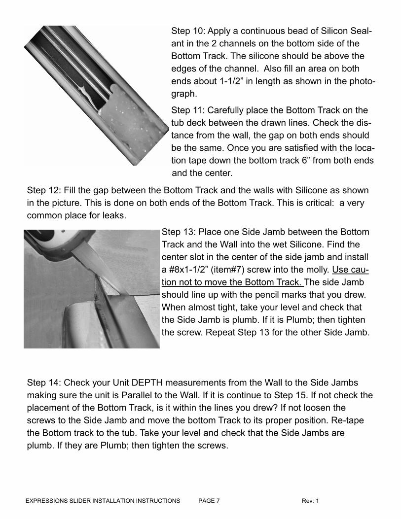
Step 10: Apply a continuous bead of Silicon Seal-
ant in the 2 channels on the bottom side of the
Bottom Track. The silicone should be above the
edges of the channel. Also fill an area on both
ends about 1-1/2” in length as shown in the photo-
graph.
Step 11: Carefully place the Bottom Track on the
tub deck between the drawn lines. Check the dis-
tance from the wall, the gap on both ends should
be the same. Once you are satisfied with the loca-
tion tape down the bottom track 6” from both ends
and the center.
Step 12: Fill the gap between the Bottom Track and the walls with Silicone as shown
in the picture. This is done on both ends of the Bottom Track. This is critical: a very
common place for leaks.
Step 13: Place one Side Jamb between the Bottom
Track and the Wall into the wet Silicone. Find the
center slot in the center of the side jamb and install
a #8x1-1/2” (item#7) screw into the molly. Use cau-
tion not to move the Bottom Track. The side Jamb
should line up with the pencil marks that you drew.
When almost tight, take your level and check that
the Side Jamb is plumb. If it is Plumb; then tighten
the screw. Repeat Step 13 for the other Side Jamb.
Step 14: Check your Unit DEPTH measurements from the Wall to the Side Jambs
making sure the unit is Parallel to the Wall. If it is continue to Step 15. If not check the
placement of the Bottom Track, is it within the lines you drew? If not loosen the
screws to the Side Jamb and move the bottom Track to its proper position. Re-tape
the Bottom track to the tub. Take your level and check that the Side Jambs are
plumb. If they are Plumb; then tighten the screws.

EXPRESSIONS SLIDER INSTALLATION INSTRUCTIONS PAGE 8 Rev: 1
Step 18:Accurately measure across the
top on the 2 Side Jambs to determine the
Header Length (item #1 on page 3)
Record the length, re-measure and com-
pare to the first number, if accurate go to
Step 19.(measure twice and cut once)
Step 19: Locate the Header and accurately
mark the Header where you are about to
cut. Place the Header in the miter box and
line up the mark on the header against the
straight slot, using a Hack Saw cut the
header to length.
Step 20: Mount the header on the top of
the 2 Side Jambs as shown.
Step 17: Go to the other Side Jamb and
Install the 3 bumpers as in Steps 15 and
16
Step 15: Locate the Bumpers (Item #4) and
the #8x1-1/2 Screws (Item #7).
Go to the Side Jamb closest to the Shower
Head and install the Center Bumper First.
Step 16: Check the Side Jamb with the
Level again and make sure it is still plumb.
If it is; install the upper and lower bumpers.
Recheck with Level again making sure the
Side Jamb is still Plumb.

EXPRESSIONS SLIDER INSTALLATION INSTRUCTIONS PAGE 9 Rev: 1
Step 22: Place a heavy towel or a mat in the tub.
Make sure the blue glass protectors are taped in-
place. Take one of the sliding doors and place it
in the tub with the rollers facing the tub wall.
Make sure the panel will not slide or move when
you exit the tub.
Step 23: Take the other glass panel and rotate it
so the rollers are facing away from the tub. Place
the glass panel in the Tub and lift it up so the roll-
ers make contact with the outside groove in the
header. Make sure that both roller assemblies
are in the Header groove. Roll the panel back
and forth they should roll smoothly.
Step 25: Get into the tub and take the other glass
panel and place the roller assemblies into the rear
groove on the header. Make sure that both roller
assemblies are in the Header groove. Roll the
panel back and forth and they should roll smooth-
ly.
Step 24: The outer glass panel should be located
on the opposite Side Jamb of the Shower Head.
Make sure you have good contact with the 3
bumpers. If they do not all make good contact with
the glass, then remove the outer panel from the
header and adjust the rollers to make good con-
tact. MAKE SURE THAT THE ROLLER SCREWS
ARE TIGHT. Reinstall the panel as in Step 23
View facing
away from the
Shower Head
Front Glass
Panel
View facing
away from the
Shower Head
Rear Glass
Panel
Step 21: On the inside face of the Header, Drill (1)
1/8” hole to the dimensions shown to secure the
header to the Side Jambs. One hole on each end
of the header. Use a Hand Screw Driver to install
the #8x1/2” screw
EXPRESSIONS SLIDER INSTALLATION INSTRUCTIONS PAGE 10 Rev: 1
Step 26: The Inside Glass panel should be located by the Shower Head. Make
sure you have good contact with the 3 bumpers. If not, remove the panel from
the header and adjust the rollers to make good contact. MAKE SURE THAT
THE ROLLER SCREWS ARE TIGHT Reinstall the panel as in Step 25
Step 27: Carefully move the 2 glass panels to one side of the unit. You will
need the Electric or Battery Drill with a # 37 Drill Bit Installed, Center Guide
(item # 11) and the 2 #6x3/8L Self-Tapping Screws (item #10), Pencil, Cen-
ter Punch, Hammer and Tape Measure. You will be working in the Tub for the
Next Step.
Step 28: Take the Center Guide and orient it in your
hand with the Curved Front facing you. Take the guide
and place the lip into the Groove in the bottom track
as shown. When in the groove, press downward on to
the Bottom Track
Step 29: Slide the Center Guide to either the Right
or Left of the center of the Bottom Track. Measure
and confirm that the Center Guide is in the middle.
Mark the hole location with the Pencil. Move the
Center Guide away from the marked locations. Us-
ing the Center Punch mark the hole centers at about
a 30° angle. Use Caution not to move the bottom
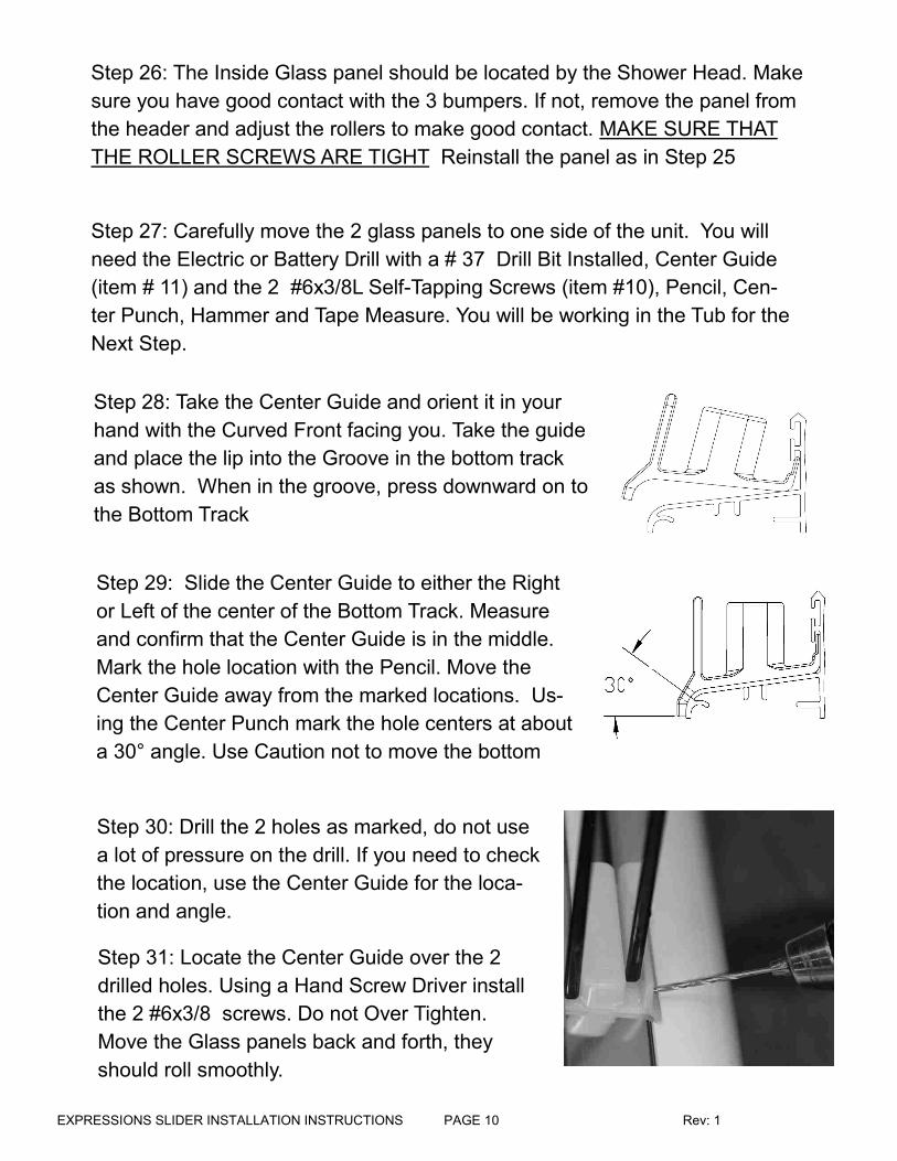
Step 30: Drill the 2 holes as marked, do not use
a lot of pressure on the drill. If you need to check
the location, use the Center Guide for the loca-
tion and angle.
Step 31: Locate the Center Guide over the 2
drilled holes. Using a Hand Screw Driver install
the 2 #6x3/8 screws. Do not Over Tighten.
Move the Glass panels back and forth, they
should roll smoothly.

EXPRESSIONS SLIDER INSTALLATION INSTRUCTIONS PAGE 11 Rev: 1
Front of Unit
Front of Front
Glass Clamp
Rear of Front
Glass Clamp
Front Anti-Jump
Screw Rear Anti-Jump
Screw
Front of Rear
Glass Clamp
Rear of Rear
Glass Clamp
Step 32: Adjusting the Anti-Jump Screws: EASCO Bi-Pass Shower Doors are
equipped with an Anti-Jump Feature. When properly adjusted the Anti-Jump
Screw will not allow the roller to jump from its track. Once the doors are aligned
and the center-guide is installed we can set the Anti-Jump Screw.
Note: This screw is deliberately tight and hard to turn. Use a hand #2 Philips
Screw Driver
Turn the Screw Clock-wise as shown below until it reaches the top of the Header.
At this point the door will not slide.
Take your screw driver and rotate the screw Counter Clock Wise 1/2 turn. The
door should now slide. Only allow enough space between the end of the screw
and the top of the header for the glass panels to ride smoothly.
Repeat the same procedure for the other Anti-Jump Screw.
Top of Header

EXPRESSIONS SLIDER INSTALLATION INSTRUCTIONS PAGE 12 Rev: 1
1
2
3
4
5
TOWEL BAR ASSEMBLY PER SIDE
ITEM QTY. DESCRIPTION
1 1 TOWEL BAR
2 4 3/4"ф WASHER
3 2 .4"ф BUSHING
4 2 RETAINING NUT
5 1 KEY
1
2
3
4
5
TOWEL BAR INSTALLATION
1) Remove 1 Towel Bar (Item 1) from the box.
2) Open the small box that containing items 2,3,4,5
3) Take the Retaining Nut (Item 4) and as-semble the Flat Washer (Item2) and then the Bushing (Item3). Repeat 3 more times.
4) Take the Towel Bar and a Washer and line them up to the HOLE in the glass.
5) Take 1 of the assemblies in step 3 and fas-ten it to the Towel Bar and Washer
6) Repeat for the other side of the Towel Bar
7) Find the Hole in the Retaining Nut, Take the Key (Item 5) and Inset it into the hole, then Tighten the Retaining Nut
8) Repeat for the other Towel Bar Assembly
1
2
3
4
5
Traditional Towel Bar Pre-Assembly
Remove the 2 tubes and the 4 Standoffs.
Hold a standoff in your hand and the tube
in the other. Press the tube into the o-ring
with a twist until the tube is fully inserted,
about a 1/2”.Repeat for the other standoff.


