
Evaporative Heater Design, Evaporative Heater Design, qualification and planningqualification and planning
M.OlceseM.Olcese
PRR SCT off-detector coolingPRR SCT off-detector cooling
13-14 March 200513-14 March 2005
PRR SCT cooling 13-14 Mar 2005 M.Olcese 2
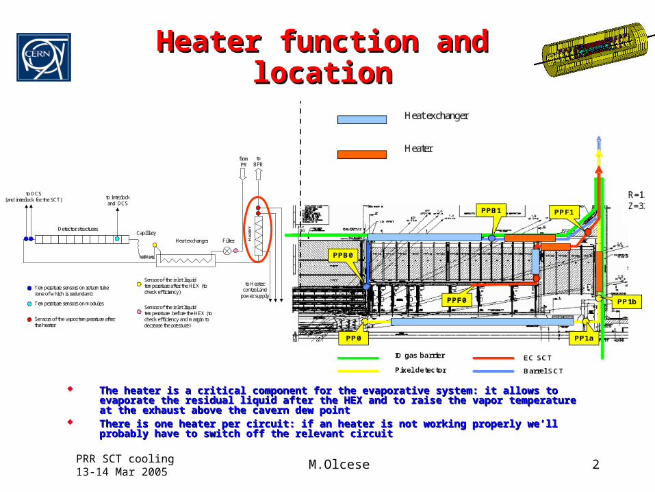
Heater function and locationHeater function and location
The heater is a critical component for the evaporative system: it allows to evaporate the The heater is a critical component for the evaporative system: it allows to evaporate the residual liquid after the HEX and to raise the vapor temperature at the exhaust above the cavern residual liquid after the HEX and to raise the vapor temperature at the exhaust above the cavern dew pointdew point
There is one heater per circuit: if an heater is not working properly we’ll probably have to There is one heater per circuit: if an heater is not working properly we’ll probably have to switch off the relevant circuit switch off the relevant circuit
to DCS (and interlock for the SCT)
to Heater control and
power supply
to interlock and DCS
to BPR
from PR
Temperature sensors on return tube (one of which is redundant)
Temperature sensors on modules
Sensor of the inlet liquid temperature after the HEX (to check efficiency)
Sensors of the vapor temperature after the heater
Heat exchanger
Detector structures
Hea
ter
Filter
Capillary
Sensor of the inlet liquid temperature before the HEX (to check efficiency and margin to decrease the pressure)

PRR SCT cooling 13-14 Mar 2005 M.Olcese 3
Heater designHeater design
Heating wire coiled inside the return tubeHeating wire coiled inside the return tube Powered 100 VDC in switching mode and controlled Powered 100 VDC in switching mode and controlled
by a PLCby a PLC Power duty cycle adjusted as function of the load on Power duty cycle adjusted as function of the load on
the detector to keep the temperature of the exhaust the detector to keep the temperature of the exhaust vapor as close as possible to the ambient temperaturevapor as close as possible to the ambient temperature
Temperature feedback provided by two thermocouples Temperature feedback provided by two thermocouples reading the vapor temperature downstream the reading the vapor temperature downstream the heating coilheating coil
One thermocouple is used for the control the second One thermocouple is used for the control the second for interlockfor interlock
In case of failure of one of the sensors the control and In case of failure of one of the sensors the control and interlock functions are cumulated on the remaining interlock functions are cumulated on the remaining sensor, but the interlock remains independent from sensor, but the interlock remains independent from the PLCthe PLC

PRR SCT cooling 13-14 Mar 2005 M.Olcese 4
HistoryHistory
First idea to use a heater with a coiled heating wire First idea to use a heater with a coiled heating wire inside the return tube is dated 3 years agoinside the return tube is dated 3 years ago
Since then two sets of prototypes have been made, Since then two sets of prototypes have been made, the second one has been used to fully qualify the the second one has been used to fully qualify the heater design and the control systemheater design and the control system
A final set of two prototypes has been ordered to A final set of two prototypes has been ordered to perform final check of performances before placing perform final check of performances before placing the production ordersthe production orders
Qualified heater design

PRR SCT cooling 13-14 Mar 2005 M.Olcese 5
Prototype qualification:Prototype qualification:tested parameterstested parameters
Temperature of heating elementTemperature of heating element Pressure dropsPressure drops Stability of the control systemStability of the control system Position of the temperature feedback sensorPosition of the temperature feedback sensor Max stable duty cycle (min power difference Max stable duty cycle (min power difference
between the nominal and maximum)between the nominal and maximum)
PRR SCT cooling 13-14 Mar 2005 M.Olcese 6
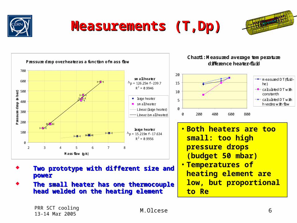
Measurements (T,Dp)Measurements (T,Dp)
Two prototype with different size and powerTwo prototype with different size and power The small heater has one thermocouple head The small heater has one thermocouple head
welded on the heating element welded on the heating element
Chart1: Measured average temperature difference heater-fluid
0
5
10
15
20
0 200 400 600 800
measured DT(fluid-he)
calculated DT withconstant h
calculated DT withh varing with flow
Pressure drop over heater as a function of mass flow
large heaterDp = 15.219mf - 17.634
R2 = 0.9956
small heaterDp = 126.25mf - 239.7
R2 = 0.9946
0
100
200
300
400
500
600
700
2 3 4 5 6 7 8
Mass flow (g/s)
Pre
ssu
re d
rop
(m
bar
)
large heater
small heater
Linear (large heater)
Linear (small heater)
• Both heaters are too small: too high pressure drops (budget 50 mbar)
• Temperatures of heating element are low, but proportional to Re
PRR SCT cooling 13-14 Mar 2005 M.Olcese 7
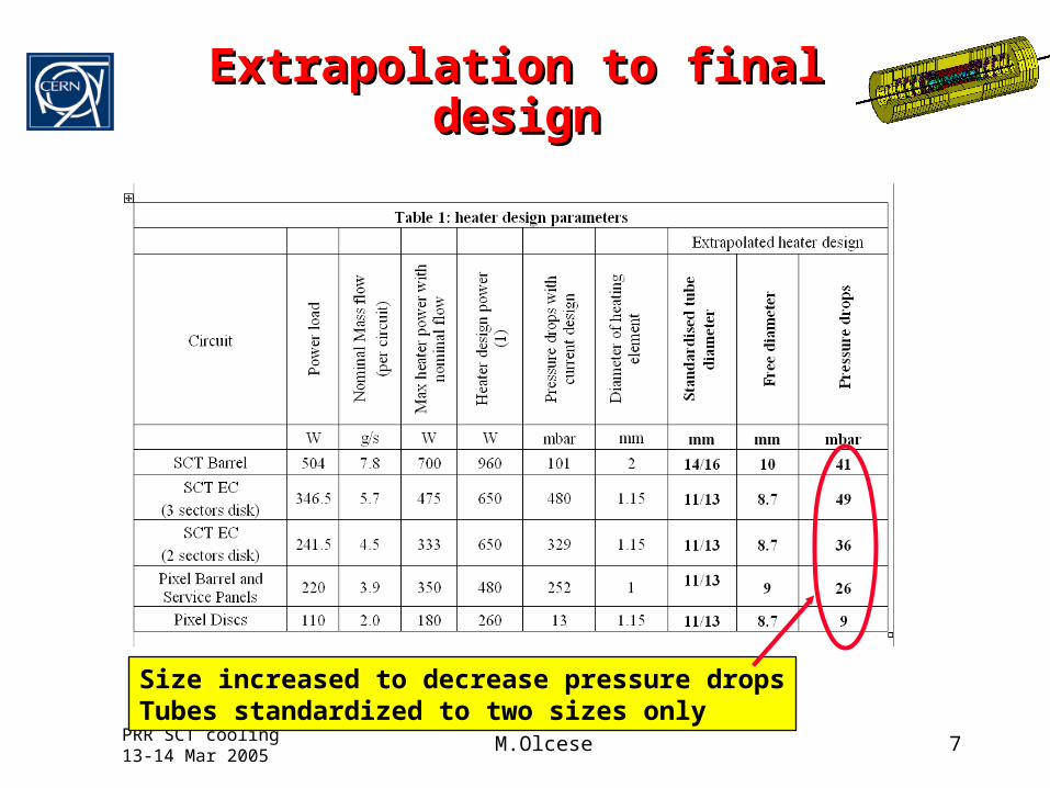
Extrapolation to final designExtrapolation to final design
Size increased to decrease pressure dropsTubes standardized to two sizes only

PRR SCT cooling 13-14 Mar 2005 M.Olcese 8
Extrapolated temperaturesExtrapolated temperatures
• SCT EC temperatures close to 100 °C
• Fluid limit is about 120 °C
• Decreasing ID by 1 mm the temperature lowers by 20 °C (and the pressure drops increase to 80 mbar)
• Wait tests on final prototype to take decision

PRR SCT cooling 13-14 Mar 2005 M.Olcese 9
Heater control testsHeater control tests PLC with simple control PLC with simple control
algorithm works algorithm works properly also with very properly also with very long temperature long temperature readout cables (150m)readout cables (150m)
Average vapor Average vapor temperature (and wall temperature (and wall temperature) function of temperature) function of power load on stave power load on stave with constant T set with constant T set point: need variable set point: need variable set to minimize to minimize DDTT
Stability good even Stability good even against sudden load against sudden load change and with T change and with T feedback sensor far feedback sensor far from the exitfrom the exit
Control OK up to a duty Control OK up to a duty cycle of 95%cycle of 95%

PRR SCT cooling 13-14 Mar 2005 M.Olcese 10
SCT barrel layoutSCT barrel layout
All details fully finalized, including layout All details fully finalized, including layout electrical connectorselectrical connectors
PRR SCT cooling 13-14 Mar 2005 M.Olcese 11
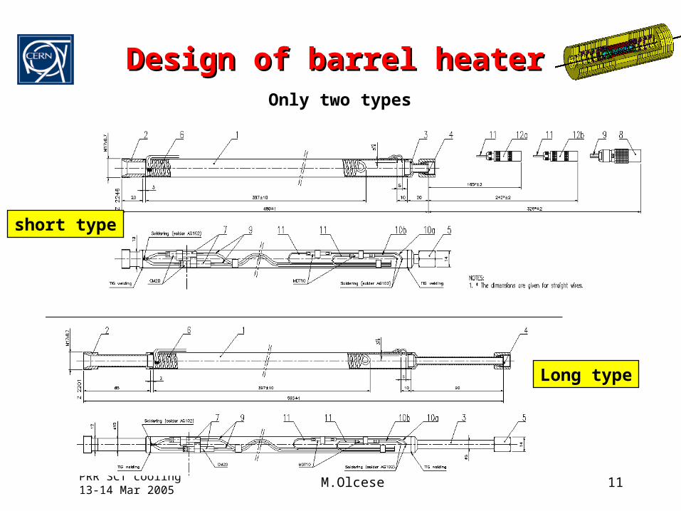
Design of barrel heaterDesign of barrel heater
Long type
short type
Only two types

PRR SCT cooling 13-14 Mar 2005 M.Olcese 12
SCT EC heater designSCT EC heater design
Various versions Various versions differing by the differing by the shape of the shape of the exhaust tube exhaust tube (driven by PPF1 (driven by PPF1 layout)layout)
Fittings are Fittings are defineddefined
Layout at PPF1 Layout at PPF1 still not finalized still not finalized (needed to fix no. (needed to fix no. of versions, of versions, position of position of electrical electrical connectors)connectors)
Still unclear if Still unclear if the tube OD the tube OD needs to needs to decrease by 1 decrease by 1 mm (see later)mm (see later)

PRR SCT cooling 13-14 Mar 2005 M.Olcese 13
SCT EC layoutSCT EC layout
Tubes from heaters to Tubes from heaters to PPF1 have different PPF1 have different shapes due to the layout shapes due to the layout of fittings at PPF1of fittings at PPF1

PRR SCT cooling 13-14 Mar 2005 M.Olcese 14
Summary of heater typesSummary of heater types
4 main 4 main classes of classes of powerpower
A multiplicity A multiplicity of subtypes of subtypes due to due to different different shape of tube shape of tube extensions extensions due to tight due to tight layoutlayout

PRR SCT cooling 13-14 Mar 2005 M.Olcese 15
Overall status Overall status (critical items in red)(critical items in red)
Final prototypes ordered: delivery mid AprilFinal prototypes ordered: delivery mid April Testing of final prototypesTesting of final prototypes should be completed by end of should be completed by end of
April as part of an SCT EC system test with pre-production April as part of an SCT EC system test with pre-production HEX and real on-detector loopsHEX and real on-detector loops
Design of SCT barrel heaters is ready, Design of SCT barrel heaters is ready, EC SCT and pixel EC SCT and pixel design (layout)design (layout) still to be finalized still to be finalized
Very specialized work: we have been dealing with only one Very specialized work: we have been dealing with only one company so far. Difficult to find qualified alternativescompany so far. Difficult to find qualified alternatives
Updated cost estimate from Thermocoax is 1500 Euro per Updated cost estimate from Thermocoax is 1500 Euro per heater. heater.
We do not need to go through a formal tendering, but a We do not need to go through a formal tendering, but a price enquire will be done anyway trying to reduce the priceprice enquire will be done anyway trying to reduce the price
Plan to place orders end of April/beginning of May (lead Plan to place orders end of April/beginning of May (lead time 5 months)time 5 months)
All heaters needed by end of the year to allow the full All heaters needed by end of the year to allow the full system commissioning before the ID installationsystem commissioning before the ID installation
PRR SCT cooling 13-14 Mar 2005 M.Olcese 16
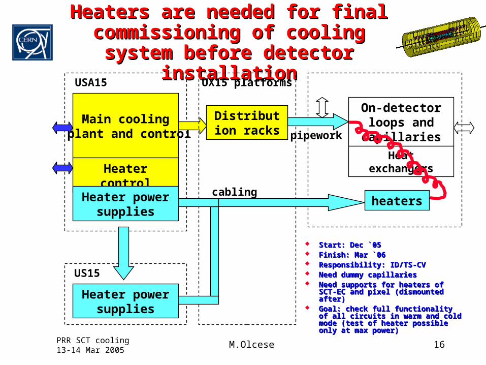
Heaters are needed for final Heaters are needed for final commissioning of cooling system commissioning of cooling system
before detector installationbefore detector installation
Main cooling plant and control
Heater control
Heater power supplies
Heater power supplies
Distribution racks
US15
USA15 UX15 platforms
On-detector loops and capillaries
heaters
pipework
cabling
Heat exchangers
Start: Dec `05Start: Dec `05 Finish: Mar `06Finish: Mar `06 Responsibility: ID/TS-CVResponsibility: ID/TS-CV Need dummy capillariesNeed dummy capillaries Need supports for heaters of SCT-EC Need supports for heaters of SCT-EC
and pixel (dismounted after)and pixel (dismounted after) Goal: check full functionality of all Goal: check full functionality of all
circuits in warm and cold mode (test circuits in warm and cold mode (test of heater possible only at max of heater possible only at max power)power)


