RESEARCH REPORT UKTRP-81-12
Evaluation of Watertight Bridge Expansion joints
by
Wm. Vernon Azevedo Research Engineer Principal
Kentucky Transportation Research Program
College of Engineering University of Kentucky Lexington, Kentucky
in cooperation with Department of Transportation Commonwealth of Kentucky
The contents of this report reflect the views
of the author who Is responsible for the facts
and accuracy of the data presented herein.
The contents do not necessarily reflect the official
views or policies of the University of Kentucky
nor of the Kentucky Department of
Transportation. This report does not constitute
a standard, specification, or regulation.
July 1981


Technical Report Documentation Page 1. Report No. 2. Government Accession No. 3. Recipient's Catalog No.
4. Title and Subtitle 5. Report Date
Watertight Julv lQRl Evaluation of Bridge Expansion Joints 6. Performing Organization Code
8. Performing Organization Report No. 7. Author! s)
Wm. Vernon Azevedo UKTRP-81-12
9. Performing Organization Name and Address 10. Work Unit No. (TRAIS)
Kentucky Transportation Research Program College of Engineering 11. Contract or Grant No.
University of Kentucky VVP.- 71-? <; Lexim<ton Kentuckv 40506 13. Type of Report and Period Covered
12. Sponsoring Agency Name and Address
Kentucky Department of Transportation Final
State Office Building 14. Sponsoring Agency Code Frankfort, Kentucky 40622
15. Supplementary Notes
Study Title: Experimental Use of Modular Expansion System In Bridges
16. Abstract
Engineers have long recognized the importance of bridge expansion joints. The inadequacy in design of such joints has also been realized. Proprietary products are now available which may eliminate well-documented problems associated with bridge expansion.
The objective of this study was to evaluate the field performance of such products.
17. Key Words 18. Distribution Statement
Expansion Joint Modular Expansion Joint Scratch Gage Linear Displacement Transducer
19. Security Clossif. (of this report) 20. Security Classif. (of this page) 21. No, of Pages 22. Price
Form DOT F 1700.7 18-721 Reproduction of completed page authorized


Table of Contents
Introduction
Structure Selection
Inspection Procedure
Prewitt Gages .
Displacement Transducers .
Joint Models .
General Observations and Conclusions .
References .
Appendix
Summary of Expansion Joint Inspections
Page
1
1
1
3
4
11
13
13
15


List of Figures
Figure 1 . Location o f experimental bridge expansion joints.
Figure 2. Prewitt scratch strain gage model SSR .
Figure 3. Scratch gage frame attached to bridge expansion joint.
Figure 4. Scratch gage frame with stiffeners
Figure 5. Schematic of the motion recorder
Figure 6. Displacement transducer motion recorder.
Figure 7. Recorded movement plotted against temperature, US 2 5 (small gage).
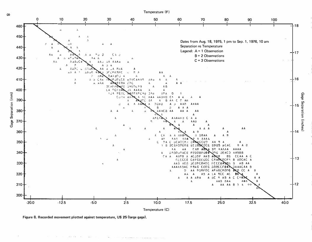
Figure 8. Recorded movement plotted against temperature, US 25 (large gage).
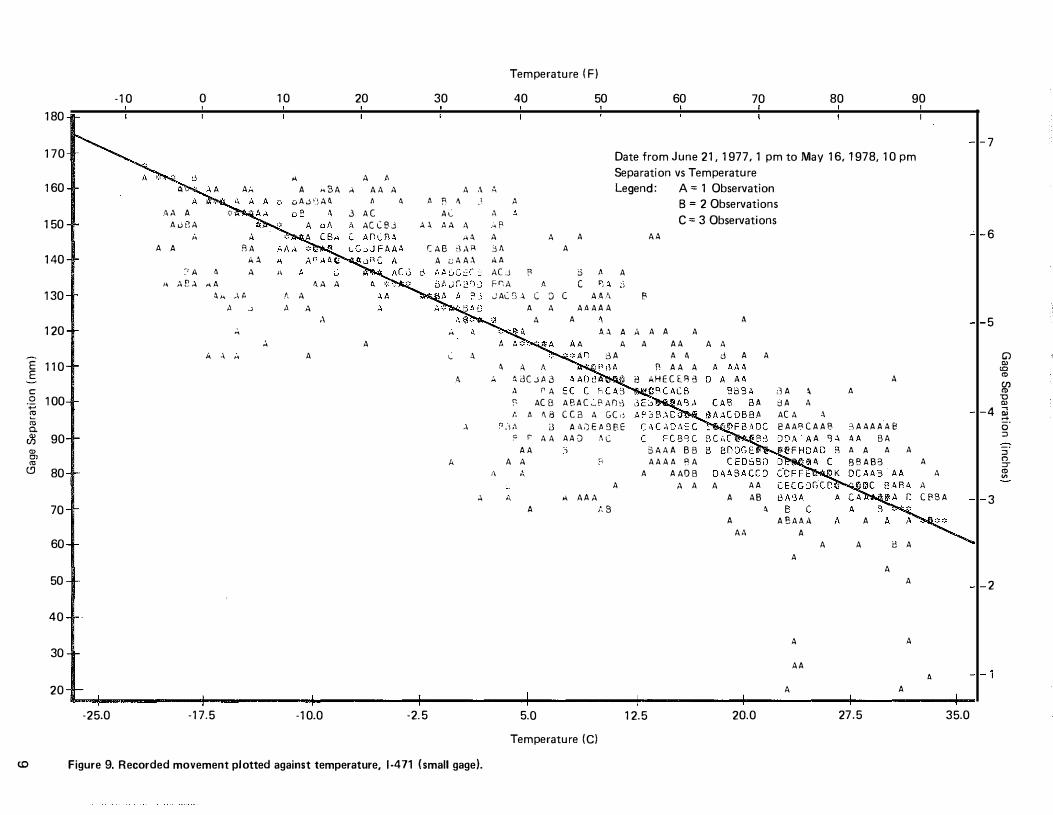
Figure 9. Recorded movement plotted against temperature, 1-471 (small gage).
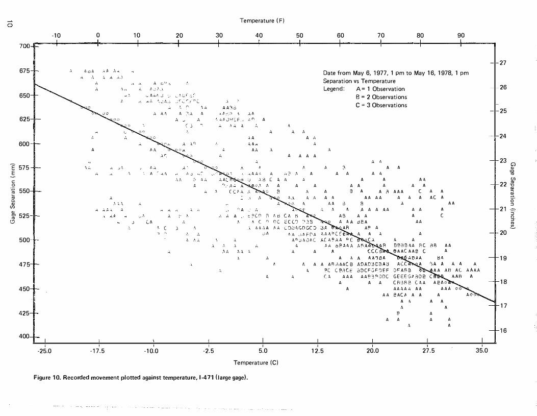
Figure 10. Recorded movement plotted against temperature, I-471 (large gage).
Appendix A.
Figure AI. Wabo-Maurer 0 1 040; joint in excellent condition.
Figure A2. Wabo-Maurer 01040; debris in gutter area. .
Figure A3. Acme Beta B1 300;joint in excellent condition; note debris above neoprene seals.
Figure A4. Acme, Acma Modular II 3M600; joint in excellent condition ; note irregularity in neoprene seal.
Figure AS. Acme, Acma Modular I I 3M600; note uneven compression of neoprene seals and
horizontal misalignment of seals and support bars.
Figure A6. Wabo-Maurer 0 1 300; note uneven compression of seals.
Figure A7. Acme, Acma Modular II 3M600; note debris above seals.
Figure AS. Acme, Acma Modular I I 3M600; note debris in gutter area.
Figure A9. Wabo-Maurer 0 1560; note cavity above seal and pavement surface and accumulation of debris.
Figure AlO. Wabo-Maurer D520; note debris above seal which is depressed below the pavement surface.
Figure All. Wabo-Maurer 0 1 300; note debris above seal which is depressed below the pavement surface.
Figure Al2. Wabo-Maurer D780; accumulation of debris above the seals.
Figure A13. Transflex 650; joint in excellent condition.
Page 2
3
3
4
4
6
7
8
9
1 0
1 7
1 7
1 8
1 9
1 9
20
2 1
22
23
24
25
26
27
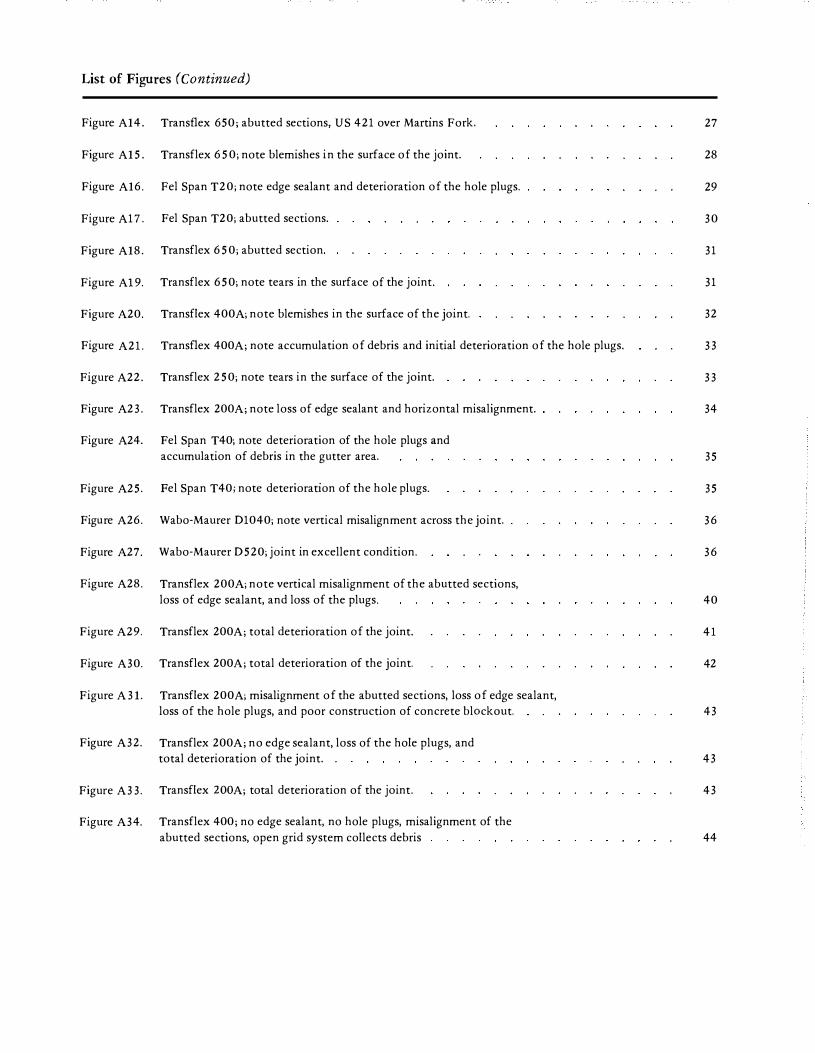
List of Figures (Continued)
Figure A14. Transflex 650; abutted sections, US 421 over Martins Fork.
Figure A15. Transflex 650; note blemishes in the surface of the joint.
Figure A16. Fel Span T20; note edge sealant and deterioration of the hole plugs.
Figure A17. Fel Span T20; abutted sections.
Figure A18. Transflex 650; abutted section.
Figure Al9. Transflex 650; note tears in the surface of the joint.
Figure A20. Transflex 400A; note blemishes in the surface of the joint.
Figure A21. Transflex 400A; note accumulation of debris and initial deterioration of the hole plugs.
Figure A22. Transflex 250; note tears in the surface of the joint.
Figure A23. Transflex 200A; note loss of edge sealant and horizontal misalignment.
Figure A24. Pel Span T40; note deterioration of the hole plugs and accumulation of debris in the gutter area.
Figure A25. Pel Span T40; note deterioration of the hole plugs.
Figure A26. Wabo-Maurer 01040; note vertical misalignment across the joint.
Figure A27. Wabo-Maurer 0520; joint in excellent condition.
Figure A28. Transflex 200A; note vertical misalignment of the abutted sections, loss of edge sealant, and loss of the plugs.
Figure A29. Transflex 200A; total deterioration of the joint.
Figure A30. Transflex 200A; total deterioration of the joint.
Figure A31. Transflex 200A; misalignment of the abutted sections, loss of edge sealant, loss of the hole plugs, and poor construction of concrete blackout.
Figure A32. Transflex 200A; no edge sealant, loss of the hole plugs, and total deterioration of the joint. .
Figure A3 3. Transflex ZOOA; total deterioration of the joint.
Figure A34. Transflex 400; no edge sealant, no hole plugs, misalignment of the abutted sections, open grid system collects debris
27
28
29
30
31
31
32
33
33
34
35
35
36
36
40
4 1
42
43
43
43
44

list of Tables
Table 1. Displacement Transducer Assembly Specifications
Table 2. Expansion Joint Data
Table 3. Theoretical Movement vs Recorded Movement
Page
5
5
6


Introduction
Bridges expand and contract, and bow and warp, in ways which are not altogether expected or predictable. Wide variations in temperatures, liveMloads, and winds induce complex forces. Lengthwise expanM sions and contractions of long bridges are the most predictable. Many bridges are supported on roller-type bearings at an end to facilitate the movement. Gaps are provided between the span and the abutment to accommodate movement. A jointingMdevice covers the gap and enables the traffic to move across on a smooth floor or deck and prevents unwanted leakage of water. Historically , jointing-devices have not proven to be durable and leak-proof.
Recent trends in bridge design toward longer spans with a minimum of expansion joints and the need for improved performance of joints have forced
industry and transportation agencies to conceive and evaluate new designs. Strip seals, joint sealants, sliding plates, and finger-joints are now being replaced by various proprietary products introduced in the last decade. Molded, neoprene rubber body joints are being used for movements up to 4 inches (102 mm). Modular expansion joints utilizing multiples of compartmental, neoprene rubber seals and steel channels are now available for movements in excess of 50 inches ( 1 .27 m).
The objective of this study was to monitor the performance of several expansion joints. Although the systems evaluated are of a proprietary nature, it is not the intent of this report to rate one product above another, but to evaluate new concepts in the design of expansion joints.
Structure Selection The bridges and the types of joints selected were
designated by the Division of Bridges of the Kentucky Department of Transportation. To ensure a broad range of conditions to which joints are exposed, the structures were chosen randomly throughout the state (Figure 1). Highways ranged from rural secondary to interstate facilities, and traffic volumes varied greatly. Locations were both rural and urban.
Simple span continuous, truss, steel deck girders, and reinforced concrete deck girders were incorporated into this study. Span length and width and skew angle varied.
As is standard on all structures constructed by the Kentucky Department of Transportation, the contractor was allowed to choose from an approved list of alternates.
Inspection Procedure Periodic field inspections were made to detect
distress in the abutting concrete attributable to an improperly functioning joint, any apparent leakage, accumulation of debris, ride quality, and noise generation. A photographic record was made. Bridge type
and dimensions, environmental conditions, joint model and installation costs, and traffic volumes are also indicated on the inspection forms. A summary of individual inspections for each structure is presented in the APPENDIX.

"' BRIDGE LOCATION KEY
1. US 27 over Kentucky River; Garrard-Jessamine Counties
2. I 24 over Cumberland River; Livingston-Lyon Counties
3. I 275 over licking River; Campbell County
4. I 275 over Ohio River; Campbell County
5. I 275 Over KV 17, Banlick Creek, and L&N RR; Kenton
County
6. I 471 over Ohio River; Campbell County
7. US 25-US 42 over Ohio River; Kenton County
8. US 421 over Martins Fork and L&N RR, Stations
221+13.96 and 238+82.44; Harlan County
9. Elmdale Road over I 24; McCracken County
10. KY 770 over Laurel River, I 75 and KV 312 Connector
Road; Laurel County
11. Prestonsburg-Pikeville Road Bridge Carrying Access Road
to KY 1426 over Levisa Fork of Island Creek, Pike
County
12. louisa-Fort Gay Bridge over Tug Fork; Lawrence County
13. Relocated Ky 225 over Cumberland River, Barbourville
Artemus Road; Knox County
14. Riverside Parkway, 13th to 17th Streets; Jefferson
County
15. Jefferson Freeway over Ramp 6, Jefferson Freeway
Kentucky Turnpike Interchange, Station 652+89.62;
Jefferson County
16. Ramp 2 over Jefferson Freeway and Preston Street,
Jefferson Freeway-Preston Street Interchange, Station
227+82.34; Jefferson County
17. Popular Level Road over Southern RR; Jefferson County
18. South Park Road over Kentucky Turnpike, Station
189+60; Jefferson County
19. US 31 over Ohio River, Clark Memorial Bridge;
Jefferson County
),: -
KENTUCKY
Figure 1. Location of experimental bridge expansion joints.

Prewitt Gages
From 1973 to 1975, attempts were made to measure joint movement with a mechanical-type strain gage (Figure 2) made by Prewitt Associates of Lexington, Kentucky. The device consisted of a Prewitt scratch gage, Model SSR, attached to U-shaped aluminum sheet metal. Each leg was attached to a girder below each side of a joint (Figure 3). As the joint expanded or contracted, the U flexed and the bending strain in the U was measured by the Prewitt scratch gage on a small brass disc. With each reversal of strain, the gage scratches the disc proportionally to the movement and advances the disc (Figure 2).
Problems with this system were encountered from the outset. Initially, records indicated other than horizontal movement of the bridge; the problem was attributed to wind vibration. Wind shields were installed; however, erroneous data were still obtained. While attempting to recalibrate the scratch mechanisms, the gages were found to be improperly attached to the sheet metal. After this problem was corrected, gage assemblies were reinstalled. Further study of the gages revealed the sheet metal was not of adequate stiffness. A nonproportional strain of the scratch gage was observed for movements of less than two inches (51 mm). Stiffners were attached (Figure 4); however, this failed to increase the sensitivity of the gages so this equipment was abandoned and other methods of measuring movement were sought.
Figure 2. Prewitt scratch strain gage model SSR.
Figure 3. Scratch gage frame attached to bridge
expansion joint.
3
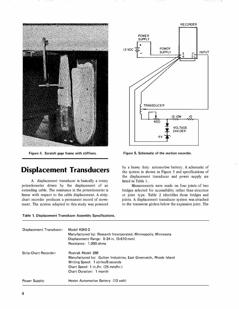
Figure 4. Scratch gage frame with stiffners.
Displacement Transducers A displacement transducer is basically a rotary
potentiometer driven by the displacement of an extending cable. The resistance in the potentiometer is linear with respect to the cable displacement. A strip· chart recorder produces a permanent record of movement. The system adapted to this study was powered
Table 1. Displacement Transducer Assembly Specifications.
Displacement Transducer: Model 4040·2
POWER
SUPPLY
+ 12VDC-=.. POWER
SUPPLY
TRANSDUCER
4V
RECORDER
3 4
I' z-
1510W 10
VOLTAGE
DIVIDER
Figure 5. Schematic of the motion recorder.
INPUT
by a heavy duty automotive battery. A schematic of the system is shown in Figure 5 and specifications of the displacement transducer and power supply are listed in Table I.
Measurements were made on four joints of two bridges selected for accessibility rather than structure or joint type. Table 2 identifies those bridges and joints. A displacement transducer system was attached to the transverse girders below the expansion joint. The
Manufactured by: Research Incorporated, Minneapolis, Minnesota Displacement Range: 0·24 in. (0-610 mm)
Strip-Chart Recorder:
Power Supply:
4
Resistance: 1,000 ohms
Rustrak Model 288 Manufactured by: Gulton Industries, East Greenwich, Rhode Island Writing Speed: 1 strike/8 seconds Chart Speed: 1 in./hr. (25 mm/hr.) Chart Duration: 1 month
Hester Automotive Battery I 12 volt)
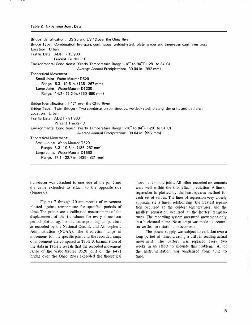
Table 2. Expansion Joint Data
Bridge Identification: US 25 and US 42 over the Ohio River Bridge Type: Combination five-span, continuous, welded-steel, plate girder and three-span cantilever truss Location: Urban Traffic Data: ADDT - 13,900
Percent Trucks- 10 Environmental Conditions: Yearly Temperature Range: -18° to 94°F (-28° to 34°C)
Average Annual Precipitation: 39.04 in. (992 mm) Theoretical Movement:
Small Joint: Wabo-Maurer D520 Range: 5.3 · 10.5 in. (135 · 267 mm)
Large Joint: Wabo-Maurer D1300 Range: 14.2 · 27.2 in. (360 ·690 mm)
Bridge Identification: I 471 aver the Ohio River Bridge Type: Twin Bridges - Two combination continuous, welded-steel, plate girder units and tied arch Location: Urban Traffic Data: ADDT · 81,800
Percent Trucks - 8 Environmental Conditions: Yearly Temperature Range: -18° to 94°F (-28° to 34°C)
Average Annual Precipitation: 39.04 in. (992 mm) Theoretical Movement:
Small Joint: Wabo-Maurer D520 Range: 5.3- 10.5 in. (135 ·267 mm)
Large Joint: Wabo-Maurer D1560 Range: 17.1-32.7 in. (435 · 831 mm)
transducer was attached to one side of the joint and the cable extended to attach to the opposite side (Figure 6).
Figures 7 through 10 are records of movement plotted against temperature for specified periods of time. The points are a calibrated measurement of the displacement of the transducer for every three-hour period plotted against the corresponding temperature as recorded by the National Oceanic and Atmospheric Administration (NOAA). The theoretical range of movement for the specific joint and the recorded range of movement are compared in Table 3. Examination of the data in Table 3 reveals that the recorded movement range cf the Wabo-Maurer D520 joint on the 1471 bridge over the Ohio River exceeded the theoretical
movement of the joint. All other recorded movements were well within the theoretical prediction. A line of regression is plotted by the least-squares method for each set of values. The lines of regression very closely approximate a linear relationship; the greatest separation occurred at the coldest temperatures, and the smallest separation occurred at the hottest temperatures. The recording system measured movement only in a horizontal plane. No attempt was made to account for vertical or rotational movements.
The power supply was subject to variation over a long period of time, creating a drift in reading actual movement. The battery was replaced every two weeks in an effort to alleviate this problem. All of the instrumentation was vandalized from time to time.
5

Table 3. Theoretical Movement vs Recorded Movement.
Figure 6. Displacement transducer
motion recorder.
Bridge Identification: US 25 and US 42 over the Ohio River
Joint
Wabo-Maurer 0520 Wabo-Maurer 01300
Joint
Wabo-Maurer 0520 Wabo-Maurer 01560
6
Theoretical Movement
5.2 in. (132 mm) 13.0 in. (330 mm)
Bridge Identification: 1�471 over the Ohio River
Theoretical Movement
5.2 in. (132 mm) 15.6 in. (396 mm)
Recorded Movement Range
3.3 in. (83.5 mm) 5.8 in. (148 mm)
Recorded Movement Range
5.7 in (145 mm) 10.4 in (264 mm)

E E c 0
·;o E rn 0. m
(/) §, rn "'
.....
110
100
90
80
70
60
50
40
30
20
Temperature (F)
0 10 20 30 40 50 ������----+-----+----r---1 4.5
" c
60 70 80 90 100
A A
A
A
·20.0 -12.5
A .. ·A-
B A A ACASB� .IJ. AA
�c
AA A A
A
A .'.,A /l, ?. :'A p A AA dAA
Jt�B -i�A A BAC
·5.0
A AA A Date from Nov. 14, 1975, 1 pm to Aug. 23,1976, 1 pm Separation vs Temperature
A A A CA
I A A '
J(�.>ACRiJ A -ASEG�DHDB -t:03A AA
AAE RGCU C�6AAD A A AA ADCAAFBAa qsp A A A A A
OA.:RCEAC.A" :JBA A A A D CF A Q A E CA� AP A AAAA.AA
Legend: A� 1 Observation B = 2 Observations C = 3 Observations
A AAgA f3 A A A "
A BABCA AA B
A AA A 3AA.t.. AOAB
C AAB
A AAA.C A
i-3 PAAA A
BA A tj,A C AA
AA A
AA A A A A CBECO .\CCC CACB
4 RCA 4 A
A"A AABOCB OEBDCAFEC CCCFBOIHC
C A? AA A BR BA A
A A
AAA
A A
•• A
AA A A
d .\
A
ABC A B AA
5 A
A AB A
A t5 A A
AA AAA7!A- S -
A A A A A3
A
BABACA A !30A ACAPB CBBCOCAFG AC BC CA AC C b..CBAC JABBDOCBB
. AA- BABAAB AA BA
A AAAAAR
AAAACBB ER�ECB BAFOF� -86"BCAACAA
BBA A C AAABC C
A A B
�B "
BACEBC_ A A 8
AA A A AE A A 38 A 3 AA A AAA
.i\ OA.Af3" /J, "t8 8-AAA A A AA B A
AABA 8 AABA A A AA A A A AAAA AAABAA AB A AAA SAB AB A u A AAA 90
BA A A A
AAA --7( . A AB A B
A
A
A A A AA CAA A C � B B
A.BABBA AA A A AAAAA AAA
A 8 A A
AAA A BAA BA CBB CA AAAA B
CBBA A BBBABAOA C( B AAA BAB B A
AA
A BA
B A ABA
A
AA A A A
A
A B A
AA BAA
A
2.5 10.0 17.5 25.0 32.5
Temperature (C) Figure 7. Recorded movement plotted against temperature, US 25 (small gage) .
4.0
3.5
3.0 Gl � � " U> "
-o � 2.5 �
a· �
� n ,.. " � 2.0
1.5
1.0
40.0
00
460
450
440
430
420
410
400
E E
390 c 0
'<0 � 380. "' 0. ru (J) 15, 370 "' (!)
360
350
340
330
320
310
300
0 10 20
" ·'
' f, ,), ,,
·' A A A
AA ,,
AA AA..J A
AA i:. ,, A \
(C ,\ A o A
/,
4
...._,_ -20.0 -12.5 -5.0
30
A
u c A
AA A ,\fl A
j A A 0A POll
·� J a C G .l ,\
" "
A A
A
A
,,
,\ A
A
Temperature (F)
40
A
A p, II
A c liC AA..>.R c c ..o1 E�r.:? 3
A
•\
50 60 70 80 90
�� (1. C) ,,
A A JAb AAA ';A A
,,, """-.. ,,
e
A
-\
Dates from Aug. 18, 1975, 1 pm to Sep. 1. 1976, 10 am Separation vs Temperature
AA A A
A A A
AB A
.:5 r ''
A A
D
Legend: A� 1 Observation
A
!\
B = 2 Observations C = 3 Observations
AA3110 E ·' A A A A
A B AA c r AH POA3 A o AAB A/JAA
B
A
c
El A A A AA AA A
A.:..AA,\ 8 C
A A
A
AA A
A A A.Aa A
A A A A A
A 8 [A A A :3 DBAA A At>
?A 'j 6
t..A AA •\ t;g.:)Q;)f!ACE
[A A Ai�PB A AC3DF AAB CCCCCE CF.FGECGGC
AA3 AC5 JCSRCBHTC
A.AA;\ABAC F8AG- CEFG A 0 AA fDBFOC
A A A A9
A A
A o
A PCAC
A A A AAA A BC R A 8 A A AAB BAA
AA
A B A e
AAAA AA:�BB
CCAA A C B BDCAC A
9 A B AA �A�� .
. 8
�� c C<-9
A A A AA B .�\ A
" A
2.5 10.0 17.5 25.0 32.5
Temperature (C)
Figure 8. Recorded movement plotted against temperature, US 25 {large gage).
100
40.0
18
17
16
Gl " "' "' (J)
15 .g " il "'-0 �
� " ::r "' 14 �
13
12
180
170
160
150
140
130
120
E 110 E c:
.Q 100 � "' ro Cl.
Jl 90 m "' ro <C) 80
70
60
50
40
30
20
-10
A
....._.... -25.0
0 10
" AA
'" A
Au8A
A A RA
AA A �'A A A "
" Af;.:< ,A
'" ·" '· A ·' A
A A
A ·\ "
-17.5
20 30
A A A A ,sA A AA A A .\
oA,J':�AO. A A A B A -' •\ 3 A C A c
,, ACC83 A> A A •\ i\4.
CAB dAR
A c.:AA.\ "
A A A
A
A
,\ " A
A
A c A
A
A
A
A
-10.0 -2.5
ID Figure 9. Recorded movement plotted against temperature, 1-471 (small gage).
Temperature I F)
40 50 60 70 80 90
Date from June 21, 1977, 1 pm to May 16, 1978, 10 pm Separation vs Temperature
.A A
.•\ eP A A jA A
A A
A(,J " FGA A JALS ..\ c 8 c
A A A
' A
A
A
3 A
c o,' A.t.../1.
Legend: A= 1 Observation B = 2 Observations C = 3 Observations
AA
A
B AAAAA
A " A A A A A
_f:<. A AA A A 3A A A d A A
A t.. dC.J/1.3 n AA A
AHECE.83
•\
,, C A r AC8 ABAC-..P.An:)
t. A <\ B CCB A G(•j a .\i'l il AA.JE!'ISBE
p r A A A A Q
A A ' A A
,,
A A AA A A
5.0
Temperature (C)
-".C •.
A
,'. 8
3AA A BB A A A A �A
A AAD B
12.5
A A A AA
A AB
A
AA
20.0
'
;3 A .\ 'dA A A( A A 2AAR(AA8
ABA AA A
A
A
AA
A
A
A
A
3AAAAAB
.. BA A A A A
BBAB3
3� A A
A B A
A A
A
A
27.5
A
A A
CPSA
A
35.0
7
6
5
G) m "' " g> '0 m
4 Ol
3
2
� o· " " " =r " �
0 Temperature (F)
-10 0 10 20 30 40 50 60 70 80 90 7oo.---+----l----+----l-----l-----1-----+----t----+----+----t----.
675
650
625
600
E 575 E c 0 -� 550 "' "-Jj w � 525
(.9
500
475
450
425
400
-25.0
AoA -�A .\ ..... 4 A � � �J
,'.
A
\,�
A ri � A c''
A �., A A.��-1
'- A;..A_ J L ,A, L: �-,'. ,.. ;, ', .. : f\,:, , ; r � � r- n C.
,, _,,;
,:._ •I
"
n \A A A� A 'A A
t," A ,,
A " A c _)
4. 4 r;
,.\, \ ,\ ,J
.\/\ (' !J. A
A ,\.<.\
"' "'A·\ .'. ' "
'
� .\ J (.A
,.. '"" ,\
A
c 3 ., '
4
.\
A
A
\ "
' A
"' ,� ).,
.\
A A16
4�:�� 1 �A .lhJU�F n A
;., -� :.. A
' A
"
AA
!:.,AA AA
A
A
_,
...,AA�'• A ,\ B
�'A ,,
A A ,\
A ,\ A
A A A A
A ;, 3 -� A
A A A A
A
A
A ,1'>, !\
,\ A A
.\ �ocn fl t,t)
-� c n ncccc'J
A
AA .• \A 1\A
clA �A ,Jll Ff'A AQ�AUtl(
.:.. .� -� i• ' .\ !\ ,\ .�
A A A A
Date from May 6, 1977, 1 pm to May 16, 1978, 1 pm
Separation vs Temperature Legend: A= 1 Observation
B = 2 Observations
C = 3 Observations
·'
,,
A
A .A A A
·\ !J.
3 A A
" A
AB
A A
A A
A A
A A A
A A
8 A A ?o AAA
AA A A A
8 A A A A .A.A
A A
DBA
AP A
.fJ. A
AA
A A
c A A
A A
A
A A
A
A A
A A
AC A
A
c
AA
BBI.�B 4A RC fiB AA
A A I}AAC AAB C A
� A B A A
' A A A AR,\AACB AC�A
A A ?C C Pc�Ct: dOCFCFJEF
(A A A A A A83QOQC
A A A CR8R� CAA
A A A 4 A I'<. AA
A A EACft A A A
A � A A
"
A A
A
A
A
A
A
A
A
-17.5 -10.0 -2.5 5.0 12.5 20.0 27.5
Temperature (C)
Figure 10. Recorded movement plotted against temperature, 1-471 (large gage).
35.0
27
26
25
24
23 G) w 'lil (f)
22 � � � "'· 0 "
21 -·
20
19
18
17
16
" " ,-�
joint Models
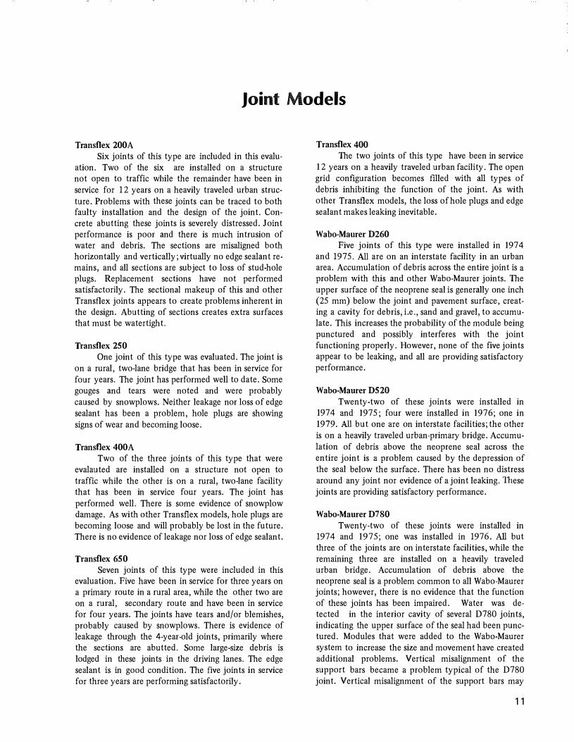
Transflex 200A Six joints of this type are included in this evalu
ation. Two of the six are installed on a structure not open to traffic while the remainder have .been in service for 1 2 years on a heavily traveled urban structure. Problems with these joints can be traced to both faulty installation and the design of the joint. Concrete abutting these joints is severely distressed. Joint performance is poor and there is much intrusion of water and debris. The sections are misaligned both horizontally and vertically; virtually no edge sealant remains, and all sections are subject to loss of stud-hole plugs. Replacement sections have not performed satisfactorily. The sectional makeup of this and other Transflex joints appears to create problems inherent in the design. Abutting of sections creates extra surfaces that must be watertight.
Transflex 250 One joint of this type was evaluated. The joint is
on a rural, two-lane bridge that has been in service for four years. The joint has performed well to date. Some gouges and tears were noted and were probably caused by snowplows. Neither leakage nor loss of edge sealant has been a problem, hole plugs are showing signs of wear and becoming loose.
Transflex 400A Two of the three joints of this type that were
evalauted are installed on a structure not open to traffic while the other is on a rural, two-lane facility that has been in service four years. The joint has performed well. There is some evidence of snowplow damage. As with other Transflex models, hole plugs are becoming loose and will probably be lost in the future. There is no evidence of leakage nor loss of edge sealant.
Transflex 65 0 Seven joints of this type were included in this
evaluation. Five have been in service for three years on a primary route in a rural area, while the other two are on a rural, secondary route and have been in service for four years. The joints have tears and/or blemishes, probably caused by snowplows. There is evidence of leakage through the 4-year-old joints, primarily where the sections are abutted. Some large�size debris is lodged in these joints in the driving lanes. The edge sealant is in good condition. The five joints in service for three years are performing satisfactorily.
Transflex 400 The two joints of this type have been in service
1 2 years on a heavily traveled urban facility. The open grid configuration becomes filled with all types of debris inhibiting the function of the joint. As with other Transflex models, the loss of hole plugs and edge sealant makes leaking inevitable.
Wabo-Maurer D260 Five joints of this type were installed in 1974
and 197 5. All are on an interstate facility in an urban area. Accumulation of debris across the entire joint is a problem with this and other Wabo-Maurer joints. The upper surface of the neoprene seal is generally one inch (25 mm) below the joint and pavement surface, creating a cavity for debris, i.e., sand and gravel, to accumulate. This increases the probability of the module being punctured and possibly interferes with the joint functioning properly. However, none of the five joints appear to be leaking, and all are providing satisfactory performance.
Wabo-Maurer D520 Twenty-two of these joints were installed in
1974 and 1975; four were installed in 1976; one in 1979. All but one are on interstate facilities; the other is on a heavily traveled urban-primary bridge. Accumulation of debris above the neoprene seal across the entire joint is a problem caused by the depression of the seal below the surface. There has been no distress around any joint nor evidence of a joint leaking. These joints are providing satisfactory performance.
Wabo-Maurer D780 Twenty-two of these joints were installed in
1974 and 1975; one was installed in 1976. All but three of the joints are on interstate facilities, while the remaining three are installed on a heavily traveled urban bridge. Accumulation of debris above the neoprene seal is a problem common to all Wabo-Maurer joints; however, there is no evidence that the function of these joints has been impaired. Water was detected in the interior cavity of several D78 0 joints, indicating the upper surface of the seal had been punctured. Modules that were added to the Wabo-Maurer system to increase the size and movement have created additional problems. Vertical misalignment of the support bars became a problem typical of the D78 0 joint. Vertical misalignment of the support bars may
11
produce some noise and ride discomfort. Uneven compression of the neoprene modules is also evident. No distress in the concrete attributable to joiut performance, and no leakage has been detected with this joiut type. The D78 0 is providing satisfactory performance.
Wabo-Maurer D l040 Niue joiuts were installed in 1974 and 1975. Five
are in urban areas and are on interstate or primary routes. The remaining four are on rural primary routes. Accumulation of debris above the neoprene seal across the entire joint is a problem as with other WaboMaurer joints. Uneven compression of the modules was noted on several joints; however, vertical misalignment of the support bars did not appear to be a problem. There has been no distress around any joint nor any evidence of leaking. These joints are providing satisfactory performance.
Wabo-Maurer Dl300 Three joints of this type were evaluated: one in
stalled in 1974, is on a heavily traveled primary facility in an urban area and the other two are on a rural iuterstate facility that has been open to traffic since the fall of 1979. The joint in service since 1974 is subject to problems common to other Wabo-Maurer joints - - that of accumulation of debris across the joint and uneven compression of the modules. However , no leakiug has been detected, and the joiut is performing satisfactorily.
Wabo-Maurer Dl560 Four joints of this type were evaluated: one was
iustalled in 1975, two in 1976, and one in 1979. Two are on a rural interstate facility and two are on an urban iuterstate facility. The two on the rural facility have been exposed to traffic since the fall of 1979 and are in excellent condition. The other two are subject to problems common to other Wabo-Maurer joints -accumulation of debris above the seal and uneven compression of the modules. Water was detected in the iuterior of the modules, iudicating the top surface of the neoprene module had been punctured or that water was entering the module from the end. There has been no evidence that the bottom sides of these modules are leaking. No distress on these decks was noted that is attributable to joint performance.
Acme, Acma Modular II 2M400 Four joints of this type were evaluated. All are
installed on a rural interstate facility and have been in service for four years. This joint is similar to the
12
Wabo-Maurer and thus experiences the same basic problems. Debris accumulates above the neoprene modules across the entire joint. Uneven compression and twisting of the modules were common. Stains on piers indicated leakage. Some noise was noted at one joiut, but this was not through! to be offensive to the traveling public.
Acme, Acma Modular II 3M600 Six of ten joints have been in service for five
years; the remaining four have been in service for four years. All are installed on rural interstate facilities. Uneven compression of the modules, accumulation of debris above the modules, and leakage indicated by stains on the piers are problems evident with this type of joint.
Acme, Acma Modular 116Ml200 Two joints have been in service for five years on
a rural iuterstate facility. The problems associated with other Acme Modular systems are also associated with the 6Ml 2 0 0. Accumulation of debris across the entire joint, uneven compression of the modules, and leakage as evidenced by stains on the piers are present. In addition, some horizontal misalignment was noted in the steel members of the joillt.
Acme, Beta B780, B1040, Bl300 Twin structures utilizing one each of the above
joints were constructed as part of a rural interstate facility. The structures were opened to traffic in December 1979. These joints are a refinement of the Acma Modular II systems. Performance expected of these joints should be comparable to that of the Acma Modular II and Wabo-Maurer systems.
Fel-Span T20 The bridge containiug the only T2 0 joiuts ill
eluded iu this evaluation was constructed iu 1977; however, the bridge has not been opened to traffic. The bridge is a two-lane facility in an urban area. Although no traffic has been allowed on the bridge, the edge sealant has become brittle and has lost adhesion to the joint and concrete surfaces. There has been no evidence of leaking, and the two joints appear to be functioning satisfactorily .
Fel-Span T40 Two joints are in a rural area on a state secon
dary road and have been in service for two years. Accumulation of debris, as with all joiut types, is a problem in the gutter areas. Hole plugs are becoming loose and some are missing. There is no evidence of leaking. They are providing satisfactory performance.
General Observations and Conclusions Virtually all of the joints inspected were filled to
some degree with incompressible debris in the traveling lanes; and all were full of debris in the gutter area. Any type of recess in the surface of the joint provides a place for debris to accumulate. Accumulation is more of a problem for the modular-type joints than the molded rubber joints . Accumulation of debris above the modules could inhibit the function of the joint and ( or) puncture the seal, allowing water to enter.
Joints installed as one continuous unit have several advantages over those that are sectionalized. Joints such as Wabo-Maurer, Acma Modular, and Acme Beta are welded to anchor bolts and thus become an integral part of the bridge deck; this is in opposition to units bolted to the deck. Continuous units eliminate possible points of leakage by having no surfaces that
have to be abutted and sealed. By virtue that no edge sealant is required, this again improves the watertightness of the joint and can eliminate future cleaning and replacing cracked and brittle edge sealant.
Both the molded neoprene rubber joints and the modular joints appear to be impr.ovements over the sliding plate and finger dams. Construction and installation problems were not addressed in this report. The final report on the National Experimental and Evaluation Program (NEEP) Project No. U relates that several states have recommended not using joint systems that require segmental installation for reasons similar to those problems experienced in Kentucky. The high installation costs of the modular systems may be negated by improved performance and reduced future maintenance needs.
References
I. Watertight Bridge Deck Joint Seals, National Experimental and Evaluation Program, Project No. 1 1 , Final Report, Jul)( 1 977.
2. Bridge Deck Joint-Sealing Systems, Evaluation
and Performance Specification, National Cooperative Highway Research Program Report 204, Transportation Research Board, June 1979.
3. Finchner, H. E.; Sixth Annual Progress Report
for Evaluation of Rubber Expansion Joints for
Bridges, Indiana State Highway Commission, June 1978.
4. Bashore, F. J . ; Evaluation of Various Bridge
Deck Joint Sealing Systems, Michigan State Highway Commission, August 1975.
5. Canfield, J. H.; and Cramer, C. L.;Development
of Watertight Bridge Deck Joint Seals, California Department of Transportation, July 1975.
6. Kozlov, G. S.; and Mehalchick, G . J.; Field
Evaluation of Various Bridge Deck Joint Seal
ing Systems, New Jersey Department of Transportation, March 1976.
7. Thornton, J. B. ; Evaluation of Existing Bridge
Expansion Joints, Georgia Department of Transportation, October 1973.
13


Appendix
SUMMARY OF EXPANSION JOINT INSPECTIONS
15


EXPANSION JOINT EVALUATION
Bridge Identification: US 27, Kentucky River County: Garrard-Jessamine Project Number. F 5 2 5 ( 1 6)
BRIDGE DESCRIPTION
Type: Twin bridges, welded steel plate girder, continuous Length, 1 , 1 05 ft(337 m) Width, 39 ft(12 m) Span Length Contributing
to Joint Movement, One @ 1 , 105 ft(337 m) Skew: 0°
ENVIRONMENTAL CONDITIONS
Yearly Temperature Range: -8° to 96°F(-22° to 36°C) Average Annual Precipitation: 45.03 in. ( 1 ,144mm) Location: Rural
JOINT DATA
Joint Type and Model: Four Wabo-Maurer D1040 Installation Date: Not Available Installation Cost: 4@ $ 1 2,000 each
Theoretical Movement of Joint Type: D 1040: 10.4 in. (264mm)
TRAFFIC DATA
AADT, 7,000 Percent Trucks: 10
INSPECTION DATA Rid� Quality, Good Noise Generation: Good
Accummulation of Debris: Heavy in gutter areas, light in traffic lanes
Joint Leaking: No evidence of leaking
Distress around joint: None
Comments: Joints are in excellent con�
clition Compression of modules is very even
No apparent vertical or hori� zontal misalign� ment of joint
Figure A1. Wabo-Maurer 0 1 040; joint in excellent con
dition.
Figure A2. Wabo-Maurer 01 040; debris in gutter area.
17
EXPANSION JOINT EVALUATION
Bridge Identification: I 24 , Cumberland River County: Livingston-Lyon Project Number: I 24- 2(26)33
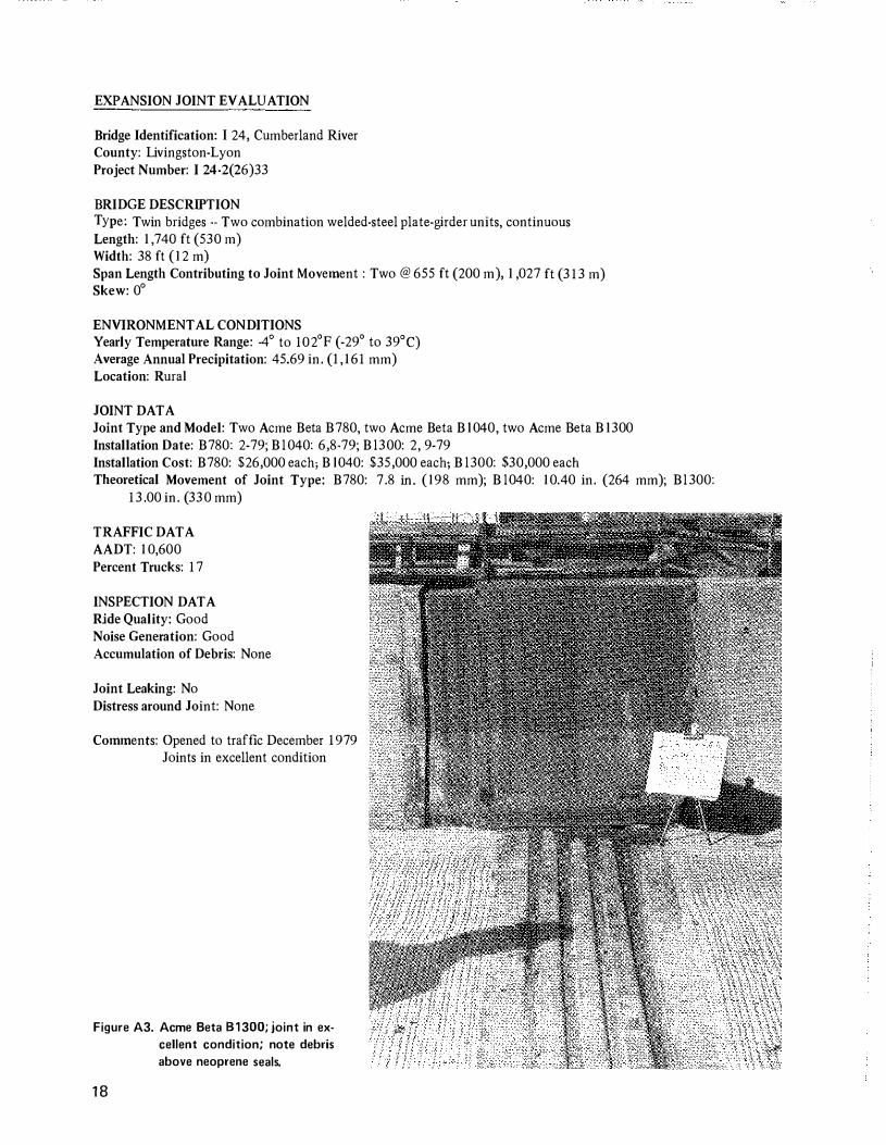
BRIDGE DESCRIPTION Type: Twin bridges -- Two combination welded-steel plate-girder units, continuous Length: 1 ,74 0 ft (53 0 m) Width: 38 ft (12 m) Span Length Contributing to Joint Movement : Two @ 655 ft (2 0 0 m) , 1 , 027 ft (3 13 m) Skew: 0°
ENVIRONMENTAL CONDITIONS Yearly Temperature Range: -4° to 102'F (-29' to 39'C) Average Annual Precipitation: 45.69 in. (I , 161 mm) Location: Rural
JOINT DATA Joint Type and Model: Two Acme Beta B78 0, two Acme Beta Bl 04 0, two Acme Beta Bl3 0 0 Installation Date: B78 0: 2-79; Bl 04 0: 6 ,8-79; Bl3 0 0: 2, 9-79 Installation Cost: B78 0: $26 , 0 0 0 each; B l 04 0: $35 , 0 0 0 each; Bl3 0 0: $3 0 , 0 0 0 each Theoretical Movement of Joint Type: B78 0: 7.8 in. (198 mm); Bl 04 0: 1 0.4 0 in. (264 mm); Bl3 0 0:
13. 0 0 in. (33 0 mm)
TRAFFIC DATA AADT: 1 0,6 0 0 Percent Trucks: 17
INSPECTION DATA Ride Quality: Good Noise Generation: Good Accumulation of Debris: None
Joint Leaking: No Distress around Joint: None
Comments: Opened to traffic December 1979 Joints in excellent condition
Figure A3. Acme Beta 81 300; joint in ex
cellent condition; note debris
above neoprene seals.
18

EXPANSION JOINT EV ALVA TION
Bridge Identification: I 275, Ucking River County: Kenton-Campbell Project Number: I 275-9(35)19
BRIDGE DESCRIPTION Type: Twin bridges, welded-steel plate girder - - simple-continuous-simple Length: 1 ,535 ft (468 m) Width: 5 0 ft (15 m) Span Length Contributing to Joint Movement: Three @ 5 15 ft (16 0 m), 795 ft (242 m), !5 0 ft (46 m) Skew: 0°
ENVIRONMENTAL CONDITIONS Yearly Temperature Range: - 18° to 94° F (-28° to 34° C) Average Annual Precipitation: 39. 04 in. (992 mm) Location: Rural
JOINT DATA Joint Type and Model: Six Acme, Acma Modular II 3M6 0 0 and two Acme, Acma Modular II 6Ml 2 0 0 Installation Date: 1974 Installation Cost: 8 @ $ 15, 0 0 0 each Theoretical Movement of Joint Type: 3M6 0 0: 6. 0 0 in. (152 mm); 6Ml 2 0 0: 12. 0 0 in. (3 05 mm)
TRAFFIC DATA AADT: 75,9 0 0 Percent Trucks: I 0
INSPECTION DATA Ride Quality: Good Noise Generation: Good Accumulation of Debris: All across joints above modules
Joint Leaking: Piers beneath joints stained -- evidence of leaking Distress around Joint: None
Comments: Uneven compression of modules evident Some horizontal misalignment of channels
Figure A4. Acme, Acma Modular II 3M600; joint in ex
cellent condition; note irregularity in neopr
ene seal.
Figure A5. Acme, Acma Modular II 3M600; note uneven
compression of neoprene seals and horizon
tal misalignment of seals and support bars.
19

EXPANSION JOINT EVALUATION
Bridge Identification: I 275, Ohio River County: Campbell Project Number: I 275-9 {48)23, I 275-9 (4 0)22
BRIDGE DESCRWTION Type: Twin Bridges, two combination welded-steel plate-girder units, continuous and continuous through
truss Lenght: 2,82 0 ft (86 0 m) Width: 5 0 ft (I 5 m) Span Length Contributing to Joint Movement: Three @ 57 0 ft (174 m), I ,44 0 ft {439 m) , 81 0 ft {247 m) Skew: 0°
ENVIRONMENTAL CONDITIONS Yearly Temperature Range: - 18° to 94°F {-28° to 34°C) Average Annual Precipitation: 39 . 04 in . {992 mm) Location: Rural
JOINT DATA Joint Type and Model: Two Wabo-Maurer 01 56 0 , two Wabo-Maurer 013 0 0, two Wabo-Maurer 052 0 Installation Date: Fall 1976 and Fall 1979 Installation Cost: D l 56 0: $5 0,44 0 each; 013 0 0: $39,2 05 each; 052 0: $3 1,34 0 each Theoretical Movement of Joint Type: Dl56 0: 1 5 .6 in. (396 mm) ; Dl3 0 0: 13 . 0 in. {33 0 mm) ; 052 0:
5 .2 in. {132 mm)
TRAFFIC DATA AADT: 5 0,2 0 0 Percent of Trucks: I 0
INSPECTION DATA Ride Quality : Good Noise Generation: Good Accumulation of Debris: None
Joint Leaking: No Distress around Joint: None
Comments: All joints in excellent condition Bridge open to traffic for only one month as of last inspection
Figure A6. Wabo-Maurer 01 300; note uneven comp
ression of seals.
20
EXPANSION JOINT EVALUATION
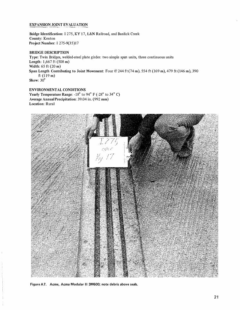
Bridge Identification: 1275 , KY 17 , L&N Railroad, and Banlick Creek County: Kenton Project Number: I 275-9(35)17
BRIDGE DESCRIPTION Type: Twin Bridges, welded-steel plate girder: two simple span units, three continuous units Length: I ,667 ft (508 m) Width: 65 ft (20 m) Span Length Contributing to Joint Movement: Four @ 244 ft (74 m) , 554 ft (169 m) , 479 ft ( 146 m) , 390
ft( 119 m) Skew: 30°
ENVIRONMENTAL CONDITIONS Yearly Temperature Range: - 18° to 94° F (-28° to 34° C) Average Annual Precipitation: 39.04 in. (992 mm) Location: Rural
Figure A7. Acme, Acma Modular II 3M600; note debris above seals.
21
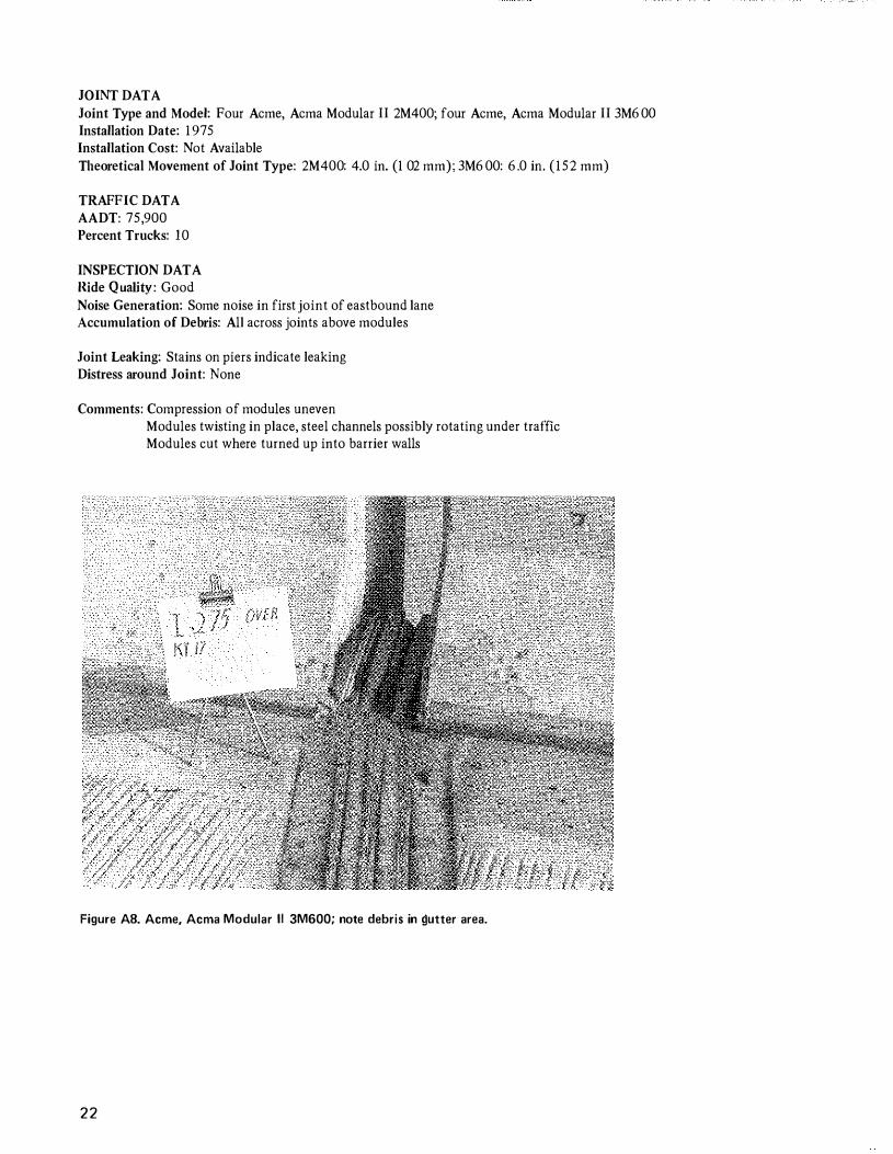
JOINT DATA Joint Type and Model: Four Acme, Acma Modular II 2M400; four Acme, Acma Modular II 3M600 Installation Date: 1975 Installation Cost: Not Available TI1eoretical Movement of Joint Type: 2M400: 4.0 in. (102 mm); 3M600: 6.0 in. (15 2 mm)
TRAFFIC DATA AADT: 75,900 Percent Trucks: I 0
INSPECTION DATA llide Q uality: Good Noise Generation: Some noise in first joint of eastbound lane Accumulation of Debris: All across joints above modules
Joint Leaking: Stains on piers indicate leaking Distress around Joint: None
Comments: Compression of modules uneven Modules twisting in place, steel channels possibly rotating under traffic Modules cut where turned up into barrier walls
Figure A8. Acme, Acma Modular II 3M600; note debris in �utter area.
22
EXPANSION JOINT EVALUATION
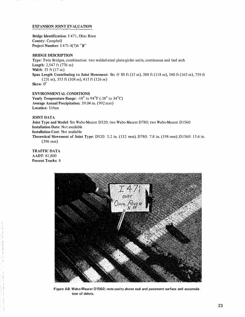
Bridge Identification: I 4 7 1 , Ohio River County: Campbell Project Number: I 471-4(7)4 "B"
BRIDGE DESCRIPTION Type: Twin Bridges, combination: two welded-steel plate-girder units, continuous and tied arch Length: 2,547 ft (776 m) Width: 55 ft (17 m) Span Length Contributing to Joint Movement: Six @ SO ft (IS m), 388 ft ( 1 18 m), 540 ft (165 m), 759 ft
(231 m), 355 ft (108 m), 4 1 5 ft (126 m) Skew: o'
ENVIRONMENTAL CONDITIONS Yearly Temperature Range: - 18' to 94'F (-28' to 34'C) Average Annual Precipitation: 39.04 in. (992 rnrn) Location: Urban
JOINT DATA Joint Type and Model: Six Wabo-Maurer D520; two Wabo-Maurer D780; two Wabo-Maurer D l560 Installation Date: Not available Installation Cost: Not available Theoretical Movement of Joint Type: DS20: 5.2 in. (132 rnm); D780: 7.8 in. (198 mm) ;D1560: 1 5.6 in.
(396 mm)
TRAFFIC DATA AADT: 81 ,800 Percent Trucks: 8
Figure A9. Wabo-Maurer 01560; note cavity above seal and pavement surface and accumula�
tion of debris.
23
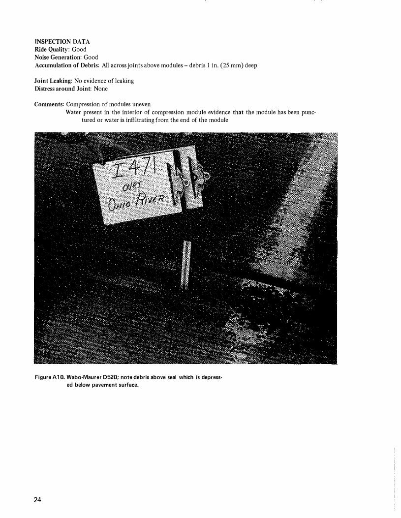
INSPECTION DATA Ride Quality: Good Noise Generation: Good Accumulation of Debris: All across joints above modules -- debris I in. (25 mm) deep
Joint Leaking: No evidence of leaking Distress around Joint: None
Comments: Compression of modules uneven Water present in the interior of compression module evidence that the module has been punc
tured or water is infiltrating from the end of the module
Figure A 1 0. Wabo-Maurer 0520; note debris above seal which is depl'ess
ed below pavement surface.
24
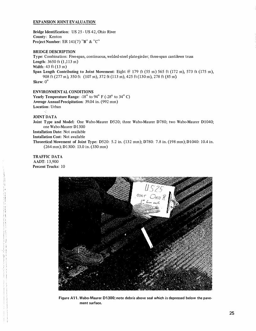
EXPANSION JOINT EVALUATION
Bridge Identification: US 25 - US 42 , Ohio River County: Ken ton Project Number: ER 141(7) "B" & "C"
BRIDGE DESCRIPTION Type: Combination: Five-span, continuous, welded-steel plate-girder; three-span cantilever truss Length: 3650 ft ( 1 ,1 13 m) Width: 43 ft ( 13 m) Span Length Contributing to Joint Movement: Eight @ 179 ft (55 m) 565 ft (172 m) , 573 ft (175 m) ,
908 ft (277 m), 350 ft ( 107 m) , 372 ft (1 13 m), 425 ft (130 m) , 278 ft (85 m) Skew: 0°
ENVIRONMENTAL CONDITIONS Yearly Temperature Range: -18° to 94° F (-28° to 34° C) Average Annual Precipitation: 39.04 in. (992 mm) Location: Urban
JOINT DATA Joint Type and Model: One Wabo-Maurer D520; three Wabo-Maurer D780; two Wabo-Maurer D 1040;
one Wabo-Maurer D1300 Installation Date: Not available Installation Cost: Not available Theoretical Movement of Joint Type: D520: 5.2 in. (132 mm); D780; 7.8 in. ( 198 mm); D\040: 10.4 in.
(264 mm); D \ 300: 13.0 in. (330 mm)
TRAFFIC DATA AADT: 1 3 ,900 Percent Trucks: 10
Figure A 1 1 . Wabo-Maurer 01 300; note debris above seal which is depressed below the pave
ment surface.
25
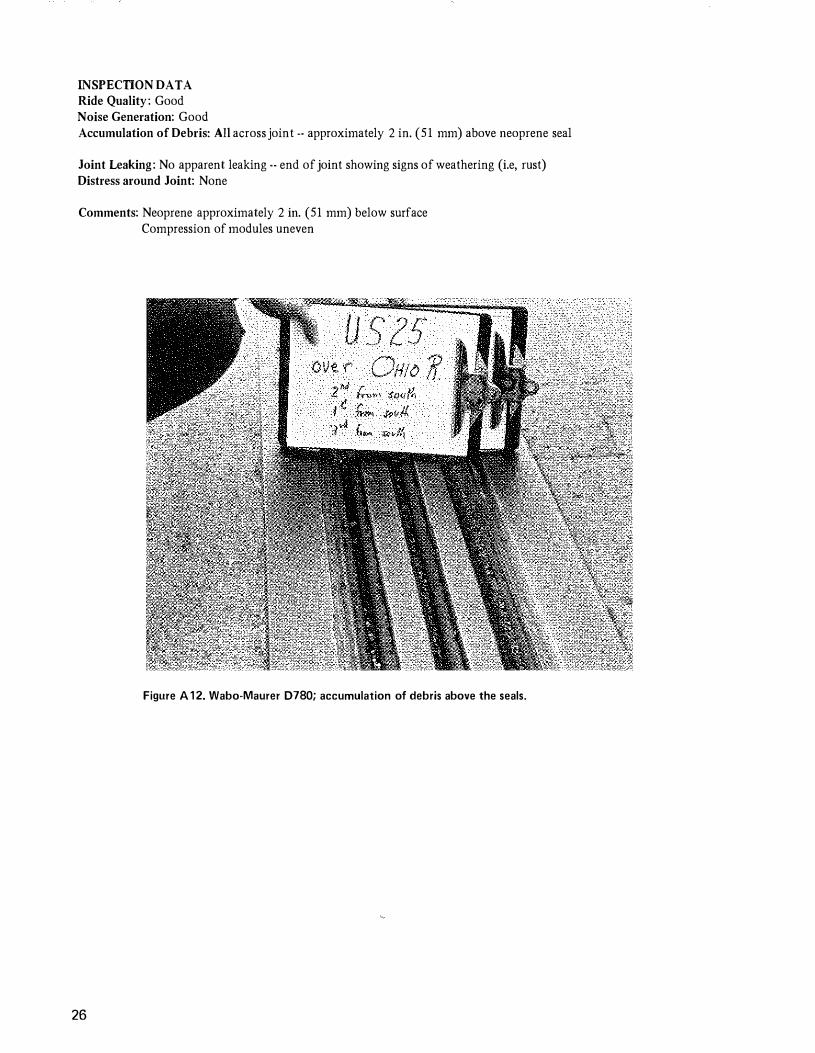
INSPECTION DATA Ride Quality: Good Noise Generation: Good Accumulation of Debris: All across joint -- approximately 2 in. (51 mm) above neoprene seal
Joint Leaking: No apparent leaking -- end of joint showing signs of weathering (i.e, rust) Distress around Joint: None
Comments: Neoprene approximately 2 in. (51 mm) below surface Compression of modules uneven
Figure A 1 2. Wabo·Maurer 0780; accumulation of debris above the seals.
26
EXPANSION JOINT EVALUATION
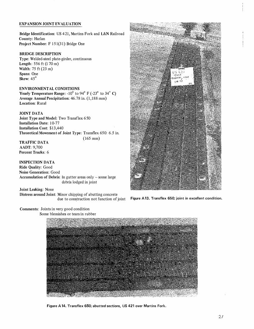
Bridge Identification: US 421, Martins Fork and L&N Railroad County: Harlan Project Number: F 1 5 1(3 1) Bridge One
BRIDGE DESCRIPTION Type: Welded-steel plate-girder, continuous Length : 556ft (170 m) Width: 75 ft (23 m) Spans: One Skew: 45'
ENVIRONMENTAL CONDITIONS Yearly Temperature Range: - 10' to 94' F (-23' to 34' C) Average Annual Precipitation: 46.78 in. (1, 188 mm) Location: Rural
JOINT DATA Joint Type and Model: Two Transflex 650 Installation Date: 10-77 Installation Cost: $13 ,440 Theoretical Movement of Joint Type: Transflex 650: 6.5 in.
( 165 mm) TRAFFIC DATA AADT: 9,700 Percent Trucks: 6
INSPECTION DATA Ride Quality: Good Noise Generation: Good Accumulation of Debris: In gutter areas only -· some large
debris lodged in joint
Joint Leaking: None Distress around Joint: Minor chipping of abutting concrete
due to construction not function of joint Figure A 13. Transflex 650; joint in excellent condition.
Comments: Joints in very good condition Some blemishes or tears in rubber
Figure A 14. Transflex 650; abutted sections, US 421 over Martins Fork.
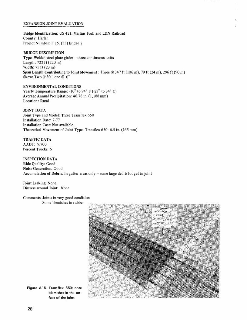
EXPANSION JOINT EVALUATION
Bridge Identification: US 421 , Martins Fork and L&N Railroad County: Harlan Project Number: F 151(33) Bridge 2
BRIDGE DESCRIPTION Type: Welded-steel plate-girder -- three continuous units Length : 722 ft (220 m) Width: 75 ft (23 rn) Span Length Contributing to Joint Movement : Three @ 347 ft (106 m), 79 ft (24 m), 296 ft (90 rn) Skew: Two @ 30°, one @ 0°
ENVIRONMENTAL CONDITIONS Yearly Temperature Range: -10° to 94° F (-23° to 34° C) Average Annual Precipitation: 46.78 in. (I , 1 88 mm) Location : Rural
JOINT DATA Joint Type and Model: Three Transflex 650 Installation Date: 7-77 Installation Cost: Not available Theoretical Movement of Joint Type: Transflex 650: 6.5 in. (165 mm)
TRAFFIC DATA AADT: 9,700 Percent Trucks: 6
INSPECTION DATA Ride Quality: Good Noise Generation: Good Accumulation of Debris: In gutter areas only -- some large debris lodged in joint
Joint Leaking: None Distress around Joint: None
Comments: Joints in very good condition Some blemishes in rubber
Figure A 1 5. Transflex 650; note
blemishes in the sur
face of the joint.
28
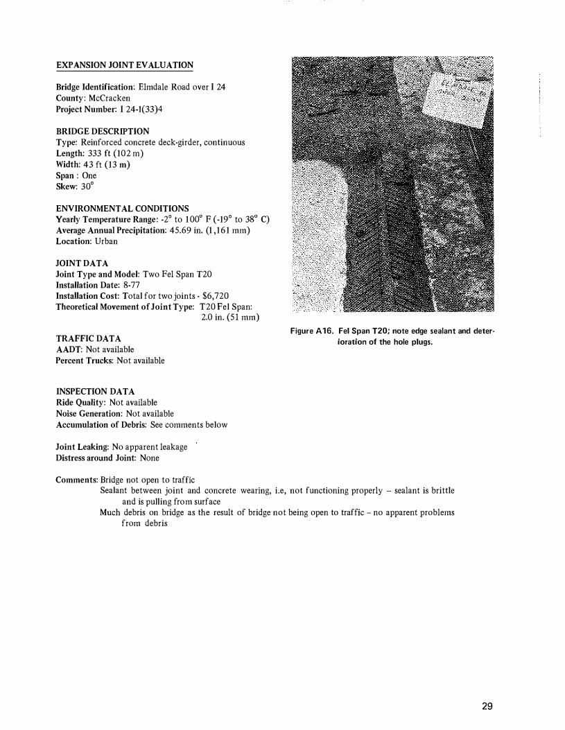
EXPANSION JOINT EVALUATION
Bridge Identification: Elmdale Road over I 24 County: McCracken Project Number: I 24-1(33)4
BRIDGE DESCRIPTION Type: Reinforced concrete deck-girder, continuous Length: 333 ft (102 m) Widtb: 43 ft (13 m) Span : One Skew: 30°
ENVIRONMENTAL CONDITIONS Yearly Temperature Range: -2° to 100° P (-19° to 38° C) Average Annual Precipitation: 45.69 in. (I , 161 mm) Location: Urban
JOINT DATA Joint Type and Model: Two Pel Span T20 Installation Date: 8-77 InstaUation Cost: Total for two joints - $6,720 Theoretical Movement of Joint Type: T20 Pel Span:
2.0 in. (51 mm)
TRAFFIC DATA AADT: Not available
Figure A16. Fel Span T20; note edge sealant and deter
ioration of the hole plugs.
Percent Trucks: Not available
INSPECTION DATA Ride Quality: Not available Noise Generation: Not available Accumulation of Debris: See comments below
Joint Leaking: No apparent leakage Distress around Joint: None
Comments: Bridge not open to traffic Sealant between joint and concrete wearing, i.e, not functioning properly -- sealant is brittle
and is pulling from surface Much debris on bridge as the result of bridge not being open to traffic -- no apparent problems
from debris
29

Figure A 17. Fe I Span T20; abutted sections.
30

EXPANSION JOINT EVALUATION
!lridge Identification: KY 770, Laurel River, ! 75, and KY 312 Connector
County: Laurel Project Number: RS 152 (5)
BRIDGE DESCRIPTION Type: Welded-steel plate-girder, continuous Length : 566 ft (172 m) Width: 29 ft (9 m) Spans: One Skew: 0°
ENVIRONMENTAL CONDITIONS Yearly Temperature Range: -12° to 96° F (-24° to 36° C) Average Annual Precipitation: 47.53 in. (1 ,207 mm) Location: Rural
Figure A 18. Transflex 650; abutted section.
JOINT DATA
Joint Type and Model: Two Transflcx 650 Installation Date: 9176 Installation Cost: Total for both, $ 1 3 ,200 Theoretical Movement of j oint Type: Transflex 6 5 0:
6.5 in. ( 1 65 mm)
TRAFFIC DATA
AADT, 3,100 Perc:ent Trucks: 8
INSPECTION DATA
Ride Quality , Good Noise Generation: Good Accumulation of Debris: Debris in gutter areas -- light
in driving lanes
Joint Leaking: Stains on abutments indicate leakage -possibly leaking is joint sealant
Distress around Joint: None
Comments: Some tears noted in rubber
Leaks could possibly occur where sections are put together
Joints appear in good condition except for tears noted in rubber
Figure A19. Transflex 650; note tears in the surface of
the joint.
31

EXPANSION JOINT EVALUATION
Bridge Identification: Prestonsburg-Pikeville Road, Access Road to KY 1426 over Levisa Fork of Island Creek
County: Pike Project Number: APD 127 ( 65)
BRIDGE DESCRIPTION Type: Welded-steel plate-girder, continuous Length: 395 ft (120 m) Width: 44 ft (13 m) Spans: One Skew: 0°
ENVIRONMENTAL CONDITIONS Yearly Temperature Range: -6° to 98°F (-21 o to 37°C) Average Annual Precipitation: 43.21 in. (1 ,098 mm) Location: Rural
JOINT DATA Joint Type and Model: One Transflex 250; One Transflex 400A Installation Date: 9-75 Installation Cost: 250 : $7,500; 400A: $10,000 Theoretical Movement of Joint Type: 250: 2.5 in. (64 nun); 400A: 4.0 in. (102 mm)
TRAFFIC DATA AADT: Not available Percent Trucks: Not available
INSPECTION DATA Ride Quality: Good Noise Generation: Good Accumulation of Debris: Much debris in joint
32
Joint Leaking: Not apparent Distress around Joint: None
Comments: Sections show signs of wear Some tears noted Plug covers becoming loose, coming out, and tearing
Figure A20. Transflex 400A; note blemishes in the sur
face of the joint.
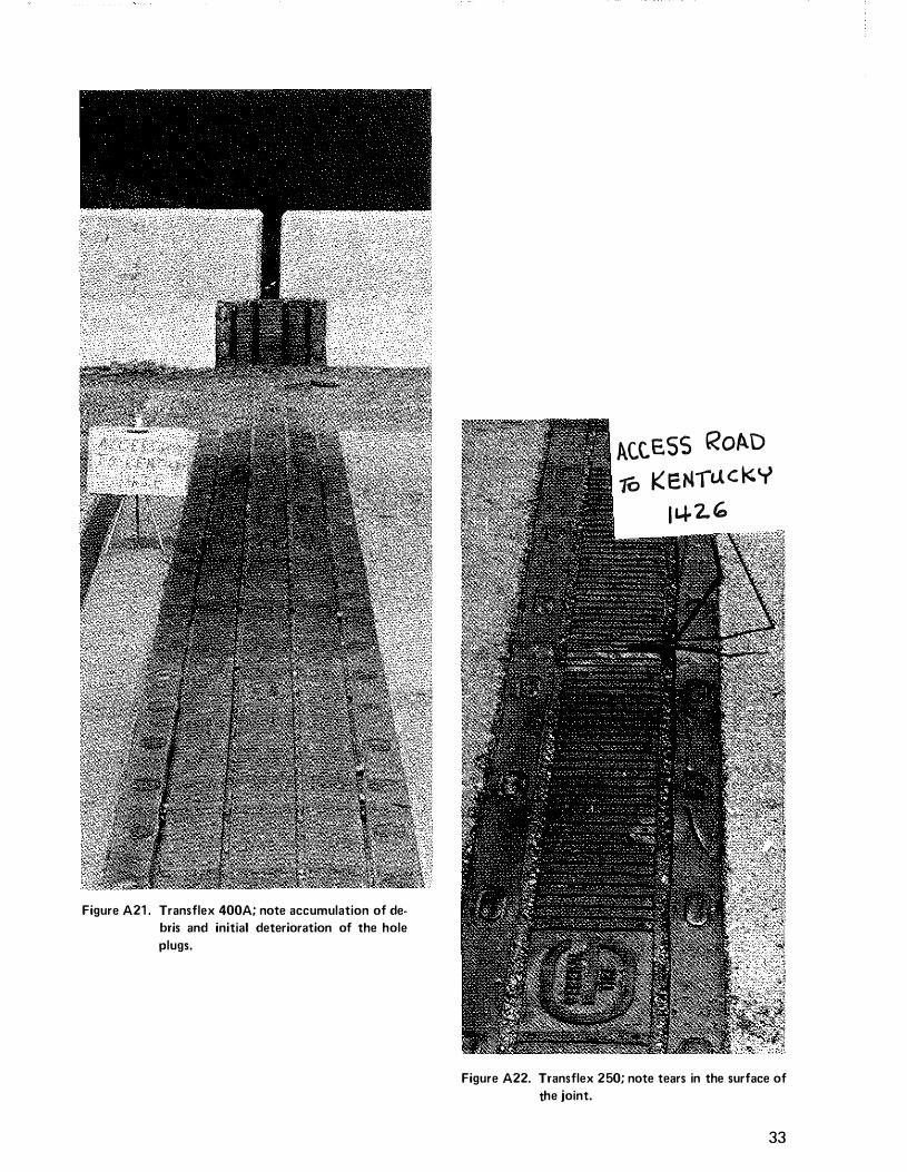
Figure A21 . Transflex 400A; note accumulation of de
bris and initial deterioration of the hole
plugs.
1\C.C.ESS RoAD
10 K EJIIauc KY
I Ll-2. '-
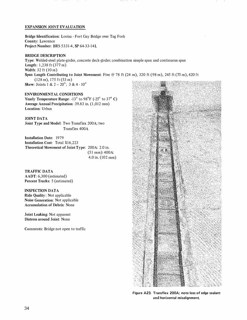
Figure A22. Transflex 250; note tears in the surface of
the joint.
33
EXPANSION JOINT EVALUATION
Bridge Identification: Louisa - Fort Gay Bridge over Tug Fork County: Lawrence Project Number: BRS 5331-4, SP 64-33-14L
BRIDGE DESCRIPTION Type: Welded-steel plate-girder, concrete deck-girder; combination simple span and continuous span Length : 1 ,238 ft (377 m) Width: 32 ft (10 m) Span Length Contributing to Joint Movement: Five @ 78 ft (24 m), 320 ft (98 m), 245 ft (75 m), 420 ft
(128 m), 175 ft (53 m) Skew: Joints 1 & 2 -- 20° ; 3 & 4 - 10°
ENVIRONMENTAL CONDITIONS Yearly Temperature Range: -13° to 98°F (-25° to 37° C) Average Annual Precipitation: 39.83 in. (1 ,012 mm) Location: Urban
JOINT DATA Joint Type and Model: Two Transflex 200A; two
Transflex 400A
Installation Date: 1979 Installation Cost: Total $16 ,223 Theoretical Movement of Joint Type: 200A: 2.0 in.
TRAFFIC DATA AADT: 6,300 (estimated) Percent Trucks: 5 (estimated)
INSPECTION DATA Ride Quality : Not applicable Noise Generation: Not applicable Accumulation of Debris: None
Joint Leaking: Not apparent Distress around Joint: None
Comments: Bridge not open to traffic
34
(5 1 mm): 400A: 4.0 in. (102 mm)
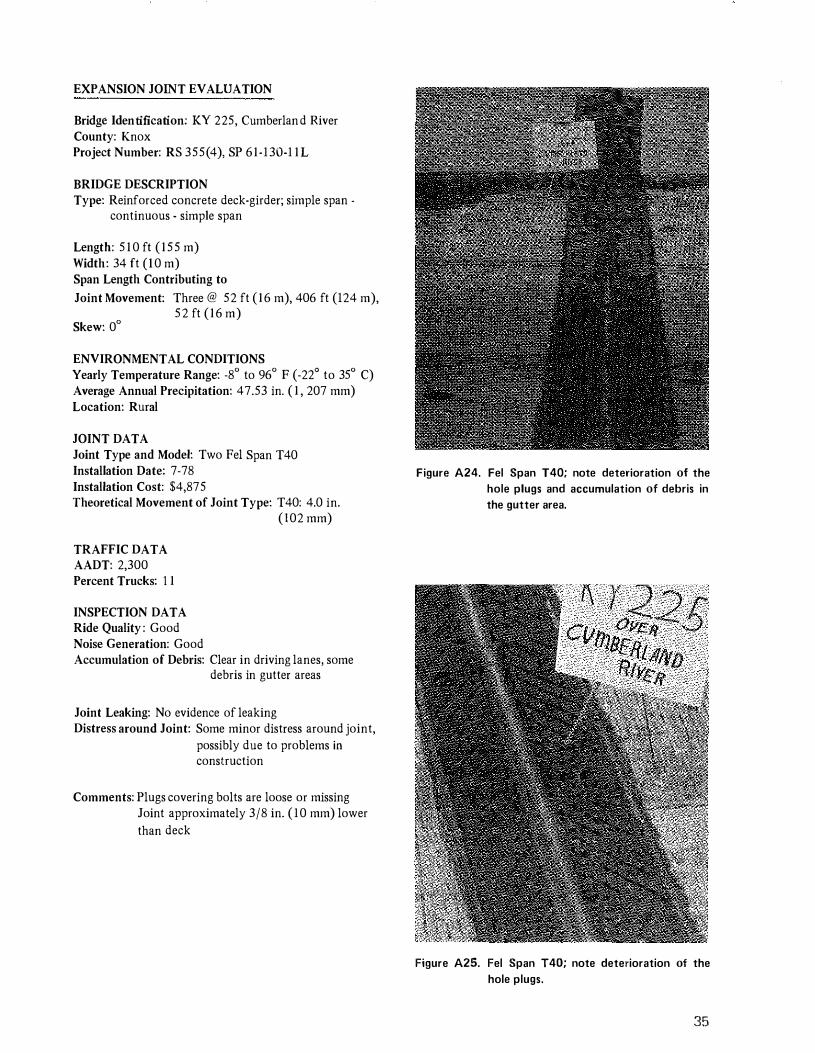
Figure A23. Transflex 200A; note loss of edge sealant
and horizontal misalignment
EXPANSION JOINT EV ALVA TION
Bridge Identification: KY 225, Cumberland River County: Knox Project Number: RS 355(4), SP 61-130-1 1L
BRIDGE DESCRIPTION Type: Reinforced concrete deck-girder; simple span
continuous - simple span
Length: 5 10 ft ( 155 m) Width: 34 ft (I 0 m) Span Length Contributing to Joint Movement; Three @ 52 ft (16 m), 406 ft (124 m),
Skew: 0° 52 ft (16 m)
ENVIRONMENTAL CONDITIONS Yearly Temperature Range: -8° to 96° F (-22° to 35° C) Average Annual Precipitation: 47.53 in. ( 1 , 207 mm) Location: Rural
JOINT DATA Joint Type and Model: Two Fel Span T40 Installation Date: 7-78 Installation Cost: $4,87 5 Theoretical Movement of Joint Type: T40: 4.0 in.
( 102 mm)
TRAFFIC DATA AADT: 2,300 Percent Trucks: 1 1
INSPECTION DATA Ride Quality : Good Noise Generation: Good Accumulation of Debris: Clear in driving lanes, some
debris in gutter areas
Joint Leaking: No evidence of leaking Distress around Joint: Some minor distress around joint,
possibly due to problems in
construction
Comments: Plugs covering bolts are loose or missing Joint approximately 3/8 in. ( 10 mm) lower than deck
Figure A24. Fel Span T40; note deterioration of the
hole plugs and accumulation of debris in
the gutter area.
Figure A25. Fel Span T40; note deterioration of the
hole plugs.
35

EXPANSION JOINT EVALUATION
Bridge Identification: Riverside Parkway - 1 3th to 17th Streets
County: Jefferson
Project Number' I 64-2(87)3
BRIDGE DESCRIPTION Type: Welded-steel plate girder, continuous units Length, 10,4 1 9 ft ( 3 , 1 7 6 m) Width , Varies 22 to 52 ft (7 to 1 6 m) Span Length Contributing to
Joint Movement: 41 spans of varing lengths from 1 1 0 ft ( 3 4 m) to 495 ft ( 1 5 1 m)
Skew: Varies
ENVIRONMENTAL CONDITIONS Yearly Temperature Range: -7° to 98° F (-22° to 3 7°C) Average Annual Precipitation: 43. 1 1 in. ( 1 ,095 mm) Location: Urban
JOINT DATA Joint Type and Model: Five Wabo-Maurer 0260; 1 8
Wabo-Maurer D520; 1 8 WaboMaurer D780; three WaboMaurer D1 040
Installation Date: 1 974 and 1975 Installation Cost: $600,000 total Theoretical Movement of
Joint Typ"' D260, 2.6 in. (66 mm); D520' 5.2 in. ( 1 3 2 mm); 0780' 7 .8 in. ( 1 98 mm); Dl 040' 10.4 in. (264 mm)
TRAFFIC DATA AADT' 63, 600 Percent Tmcks: 1 0
INSPECTION DATA Ride Quality, Good
Noise Generation: See below Accumulation of Debris: Excessive in gutter
area, all across joint
J oint Leaking: Not evident Distress Around Joint: None
COMMENTS Several joints loud under traffic as a result of steel channels moving under traffic and plates becoming loose. Vertical misalignment between channels noted on several joints.
Figure A26. Wabo-Maurer 01 040; note vertical misalign
ment across the joint.
Figure A27. Wabo-Maurer 0520; joint in excellent condition.
36

EXPANSION JOINT EVALUATION
Bridge Identification: Jefferson Freeway over Ramp 6: Jefferson Freeway County: Jefferson Kentucky Turnpike Interchange Project Number: F 552(12); SP56468-1 5L
BRIDGE DESCRIPTION Type: Continuous, welded-steel plate-girder Length: 200 ft (61 rn) Width: 40 ft (12 m) Span Length Contributing to Joint Movement: One @ 200 ft (61 rn) Skew: 3°
ENVIRONMENTAL CONDITIONS Yearly Temperature Range: -7° to 98° F (-22° to 37° C) Annual Precipitation: 43. 1 1 in. (1 ,095 mm) Location: Rural
JOINT DATA Joint Type and Model: Installation Date: Installation Cost: Theoretical Movement of Joint Type:
TRAFFIC DATA AADT: 53,600 (estimated) Percent Trucks: 10 (estimated)
INSPECTION DATA Ride Quality: Noise Generation: Accumulation of Debris:
Joint Leaking: Distress around Joint:
Comments: Contract has not been let
37

38
EXPANSION JOINT EVALUATION
Bridge Identification: Poplar Level Road over Southern Railroad County: Jefferson Project Number: U 553 (3)
BRIDGE DESCRIPTION Type: 17�span, precast, prestressed concrete 1-beam Length: 1 ,143 ft (348 m) Width: 68 ft (2 1 m) Spans: 17 Skew: 0°
ENVIRONMENTAL CONDITIONS Yearly Temperature Range: -7° to 98°F (-22° to 37°C) Average Annual Precipitation: 43,1 I in. ( 1 ,095 mm) Location: Urban
JOINT DATA Joint Type and Model: Installlation Date: Installation Cost: Theoretical Movement of Joint Type:
TRAFFIC DATA AADT: 39,700 Percent Trucks: I I
INSPECTION DATA Ride Quality: Noise Generation: Accumulation of Debris:
Joint Leaking: Distress around Joint:
Comments: Contract has not been let
EXPANSION JOINT EVALUATION
Bridge Identification: Southpark Road over Kentucky Turnpike County: Jefferson Project Number: F 552(12); SP 56-468-ISL
BRIDGE DESCRIPTION Type: Combination simple span -- continuous span -- simple span; welded-steel plate-girder Length; 377 ft (I I S m) Width: 44 ft (13 m) Span Length Contributing to Joint Movement: Three @ 43 ft (13 m), 291 ft {89 m), 43 ft (13 m) Skew: 0°
ENVIRONMENTAL CONDITIONS Yearly Temperature Range: -7° to 98°F (-22° to 37°C) Average Annual Precipitation: 43 . 1 1 in. (I ,095 mm) Location: Rural
JOINT DATA Joint Type and Model: Installation Date: Installation Cost: Theoretical Movement of Joint Type
TRAFFIC DATA AADT: 9,700 Percent Trucks: 3
INSPECTION DATA Ride Quality Noise Generation: Accumulation of Debris:
Joint Leaking: Distress around Joint:
Comments: Contract has not been let
39
EXPANSION JOINT EVALUATION
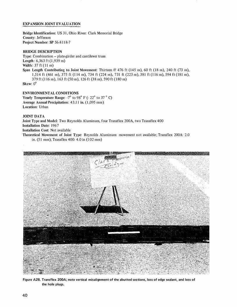
Bridge Identification: US 3 1 , Ohio River: Clark Memorial Bridge County: Jefferson Project Number: SP 56-8 1 1 8-7
BRIDGE DESCRIPTION Type: Combination -- plate-girder and cantilever truss Length : 6,363 ft (1 ,939 m) Width : 37 ft ( I I m) Span Length Contributing to Joint Movement: Thirteen @ 476 ft (145 m), 60 ft (18 m), 240 ft (73 m),
1 ,5 14 ft (461 m), 375 ft (1 14 m), 734 ft (224 m), 731 ft (223 m), 381 ft (1 16 m), 594 ft (181 m), 379 ft (1 16 m), 1 63 ft (50 m), 126 ft (38 m), 590 ft ( 180 m)
Skew: 0°
ENVIRONMENTAL CONDITIONS Yearly Temperature Range: -7° to 98° F (· 22° to 37 o C) Average Annual Precipitation: 43.1 1 in. (1 ,095 mm) Location: Urban
JOINT DATA Joint Type and Model: Two Reynolds Aluminum, four Transflex 200A, two Transflex 400 Installation Date: 1967 Installation Cost: Not available Theoretical Movement of Joint Type: Reynolds Aluminum: movement not available ; Transflex 200A: 2.0
in. (5 1 mm); Transflex 400: 4.0 in (I 02 mm)
Figure A28. Transflex 200A; note vertical misalignment of the abutted sections, loss of edge sealant, and loss of
the hole plugs.
40

TRAFFIC DATA AADT: 19,600 (estimated) Percent Trucks: 4 (estimated)
INSPECTION DATA Ride Quality : Poor -- due to distress around joints and joints being loose Noise Generation: Poor -- due to distress around joints and joints being loose Accumulation of Debris: Much debris
Joint Leaking: All joints -- due to distress and lack of sealant Distress around Joint: Severe
Figure A29. Transflex 200A; total deterioration of the joint.
41

Comments: Reynolds Aluminum joint -- distress severe around joint -- noise due to contact of aluminum plates
Transflex 200A -- loss of plug covers, sections of joint not properly installed, edges have little or no sealant, intrusion of debris and water, leakage severe due to poor joint and pavement performance, sections misaligned both vertically and horizontally, partial sections missing
Transflex 400 -- waffle design fills with debris, loss of plug covers, loss of joint sealant, deterioration around joints, leaking inevitable
Figure A30. Transflex 200A; total deterioration of the joint.
42
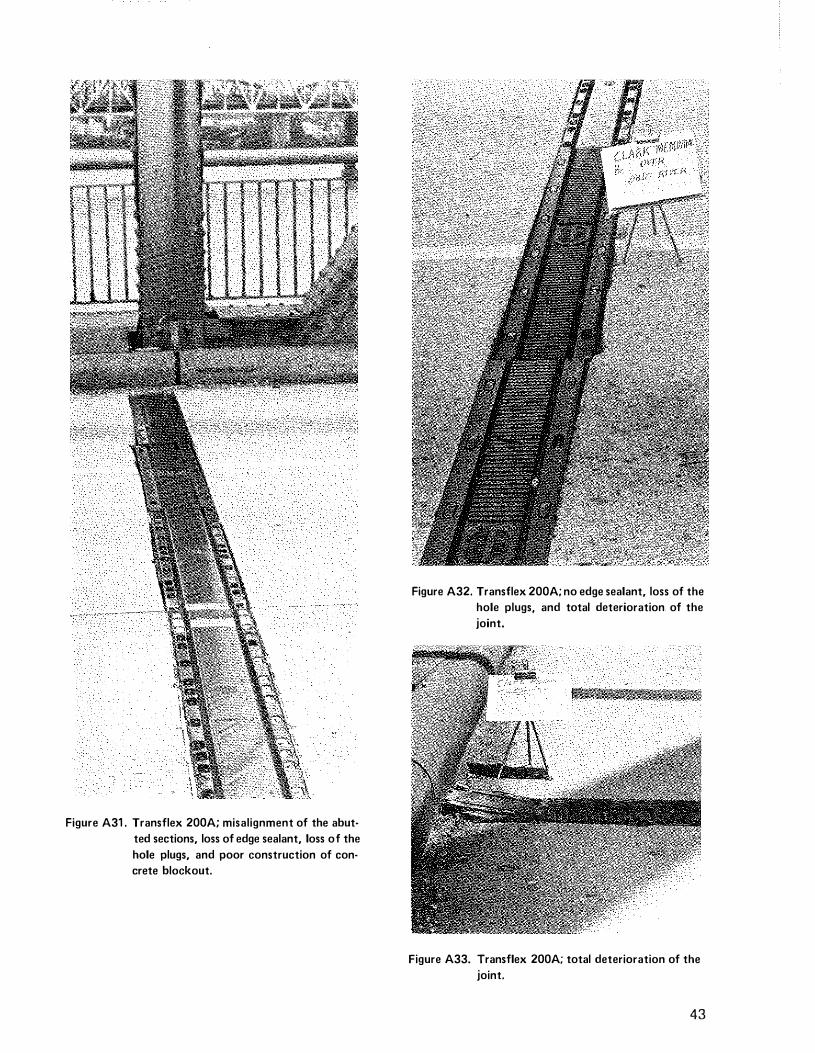
Figure A31 . Transflex 200A; misalignment of the abut
ted sections, loss of edge sealant, loss of the
hole plugs, and poor construction of con
crete blackout.
Figure A32. Transflex 200A; no edge sealant, loss of the
hole plugs, and total deterioration of the
joint.
Figure A33. Transflex 200A; total deterioration of the
joint.
43
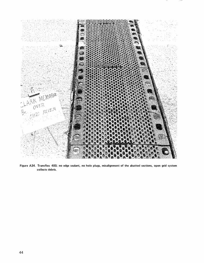
Figure A34. Transflex 400; no edge sealant, no hole plugs, misalignment of the abutted sections, open grid system
collects debris.
44
EXPANSION JOINT EVALUATION
Bridge Identification: Ramp 2 over Jefferson Freeway and Preston Street County: Jefferson Project Number: F 552(12) SP56-468-1 5L
BRJDGE DESCRJPTION Type: Continuous, welded-steel plate-girder Length: 366 ft (1 1 2 m) Width: 38 ft (12 m) Span Length Contributing to Movement: One @ 366 ft (1 1 2 m) Skew: Varies
ENVIRONMENTAL CONDITIONS Yearly Temperature Range: -7° to 98°F (-22° to 37°C) Average Annual Precipitation: 43. 1 1 in. (I ,095 mm) Location: Urbao
JOINT DATA Joint Type and Model: Installation Date: Installation Cost: Theoretical Movement of Joint Type:
TRAFFIC DATA AADT: Percent of Trucks:
INSPECTION DATA Ride Quality: Noise Generation: Accumulation of Debris:
Joint Leaking: Distress around Joint:
Comments: Contract has not been let
45


