Download - EVALUATION OF NON-CONFORMING PILES - STGEC

© 2016 HDR, Inc., all rights reserved.
EVALUATION OF NON-CONFORMING PILES
Minimum Tip Elevation Required Driving Resistance Geometrical Tolerance Pile Damage
TOPICS
2
Minimum tip elevation most often set to provide fixity at the pile toe
Highly variable subsurface conditions can be impediments to reaching minimum tip
NCDOT: US 421 Bridge over Fishing Creek – Emergency project after Hurricane washed out the roadway
Scenario to consider: Many piles do not reach minimum tip elevation
MINIMUM TIP ELEVATION
3

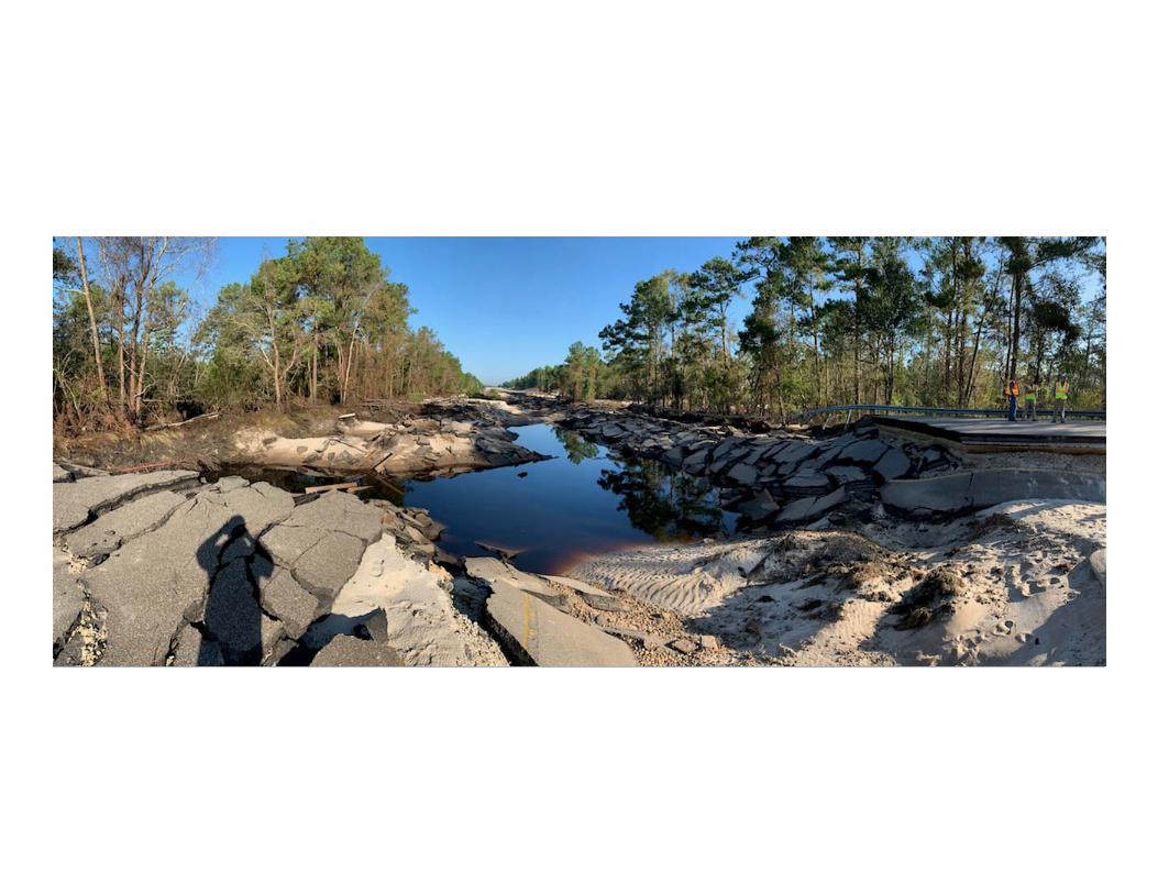
Roadway badly damaged
Emergency design requested by NCDOT
Partially inaccessible for drill rig access
US 421 AT FISHING CREEK AFTER HURRICANE FLORENCE


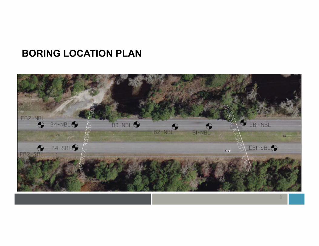
BORING LOCATION PLAN
8
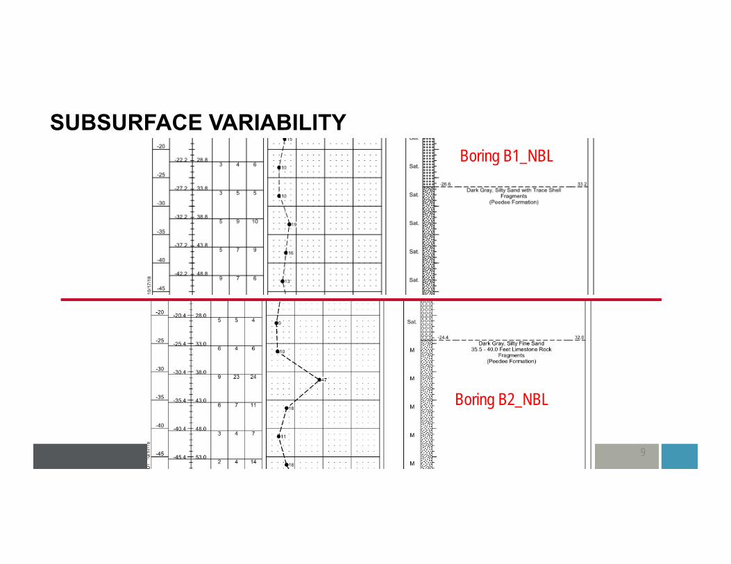
SUBSURFACE VARIABILITY
9
Boring B1_NBL
Boring B2_NBL
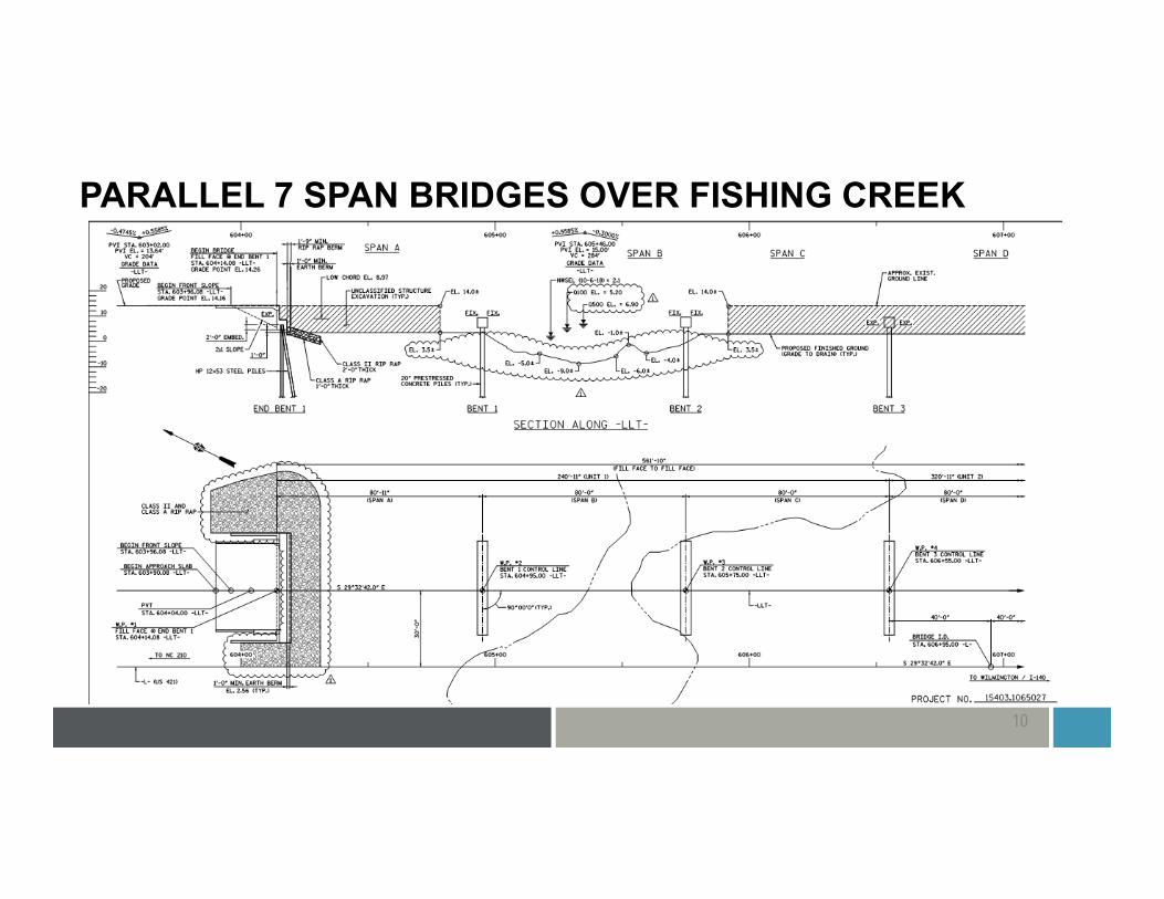
PARALLEL 7 SPAN BRIDGES OVER FISHING CREEK
10
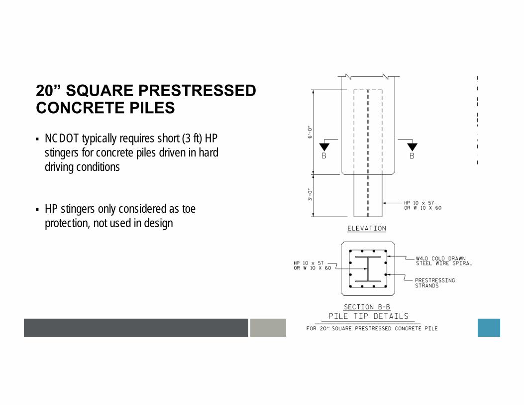
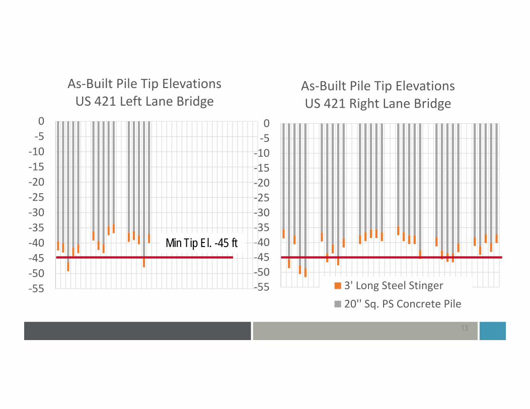
20” SQUARE PRESTRESSED CONCRETE PILES
11
NCDOT typically requires short (3 ft) HP stingers for concrete piles driven in hard driving conditions
HP stingers only considered as toe protection, not used in design
12
‐55‐50‐45‐40‐35‐30‐25‐20‐15‐10‐50
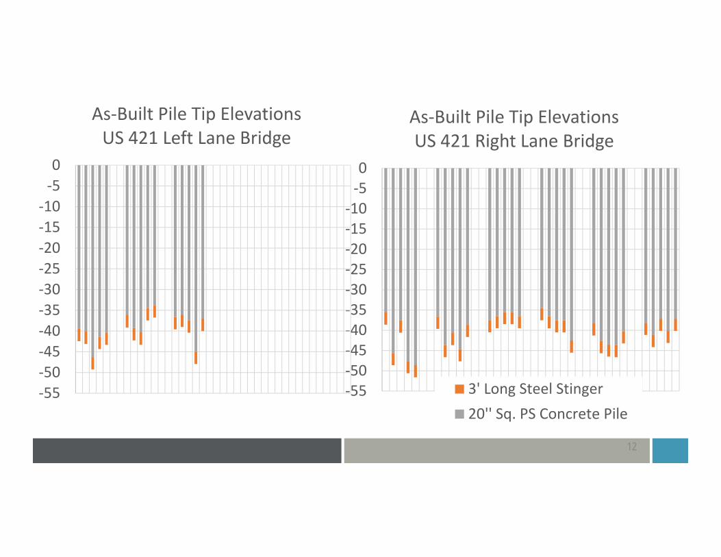
As‐Built Pile Tip ElevationsUS 421 Right Lane Bridge
3' Long Steel Stinger20'' Sq. PS Concrete Pile
‐55‐50‐45‐40‐35‐30‐25‐20‐15‐10‐50
As‐Built Pile Tip ElevationsUS 421 Left Lane Bridge
13
‐55‐50‐45‐40‐35‐30‐25‐20‐15‐10‐50
As‐Built Pile Tip ElevationsUS 421 Right Lane Bridge
3' Long Steel Stinger20'' Sq. PS Concrete Pile
‐55‐50‐45‐40‐35‐30‐25‐20‐15‐10‐50
As‐Built Pile Tip ElevationsUS 421 Left Lane Bridge
Min Tip El. -45 ft

CAPWAP SUMMARY BENT 2 PILE 5
14
HP stinger showing ~123 kips of resistance at 10.7 ksf unit skin friction
API RP2A guidelines for siliceous sand indicate maximum 2.4 ksf unit skin friction for very dense sand and gravel
8+ ksf likely limestone
3 ft long HP stinger ->>
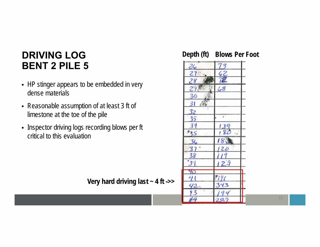
DRIVING LOGBENT 2 PILE 5
15
HP stinger appears to be embedded in very dense materials
Reasonable assumption of at least 3 ft of limestone at the toe of the pile
Inspector driving logs recording blows per ft critical to this evaluation
Very hard driving last ~ 4 ft ->>
Depth (ft) Blows Per Foot
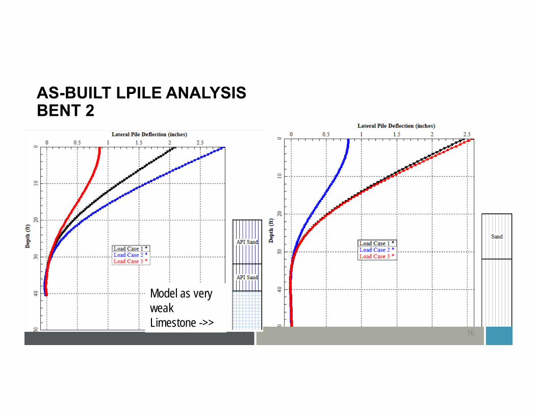
AS-BUILT LPILE ANALYSISBENT 2
16
Model as very weak Limestone ->>

Minimum Tip Elevation Required Driving Resistance Geometrical Tolerance Pile Damage
TOPICS
17
Insufficient axial resistance at the final pile tip elevation
Common problem with PS concrete piles in coastal geology, particularly when splicing is not allowed
NCDOT: Bonner Bridge Replacement project
Scenario to consider: A few piles have insufficient axial resistance but others have excess resistance
REQUIRED DRIVING RESISTANCE
18

Evaluate actual pile loading against PDA test data and pile driving logs rather than applying maximum pile load to all pileso Driving resistance can be estimated from pile driving logs using a refined wave equation
analysis in GRLWEAP
Calibrate axial stiffness of soils (T-Z and Q-Z) curves such that the load on the pile is limited to the driving resistance from PDA or driving logs
Superposition of skin friction and end bearing for displacement piles
REQUIRED DRIVING RESISTANCE – POTENTIAL SOLUTIONS
19
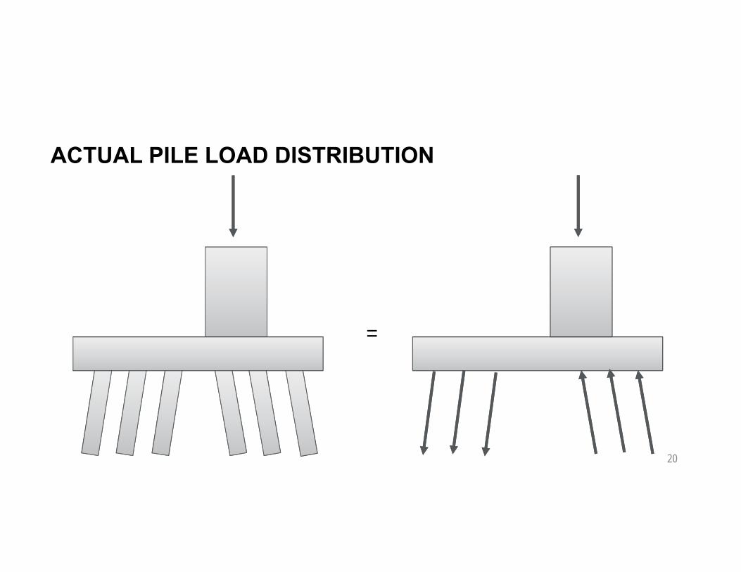
ACTUAL PILE LOAD DISTRIBUTION
20
=

ACTUAL PILE LOAD DISTRIBUTION
21
=
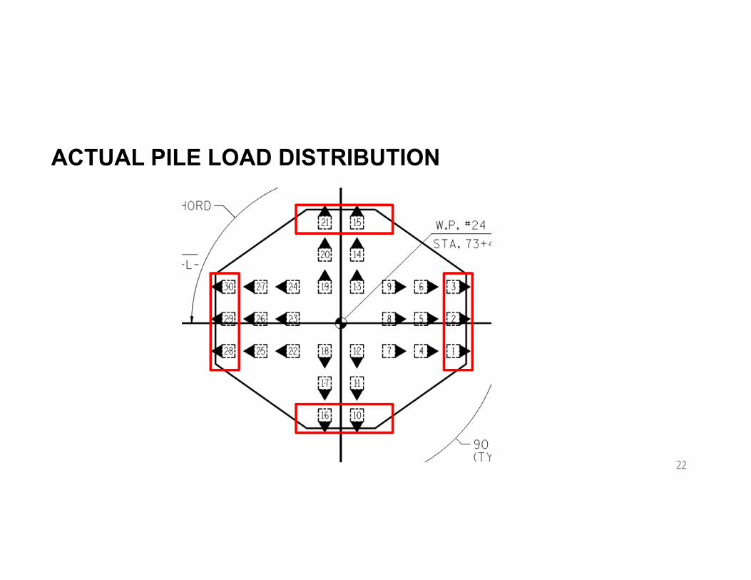
ACTUAL PILE LOAD DISTRIBUTION
22
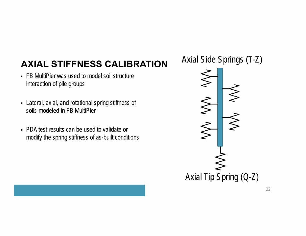
FB MultiPier was used to model soil structure interaction of pile groups
Lateral, axial, and rotational spring stiffness of soils modeled in FB MultiPier
PDA test results can be used to validate or modify the spring stiffness of as-built conditions
AXIAL STIFFNESS CALIBRATION
23
Axial Side Springs (T-Z)
Axial Tip Spring (Q-Z)
Driven Pile (McVay) T-Z and Q-Z models utilized
T-Z inputs: ultimate unit side friction, Poisson’s ratio, shear modulus
Q-Z inputs: ultimate tip resistance, Poisson’s ratio, shear modulus
High confidence in ultimate values, low confidence in shear modulus values based on routine test methods
AXIAL SOIL SPRING PARAMETERS (T-Z AND Q-Z)
24
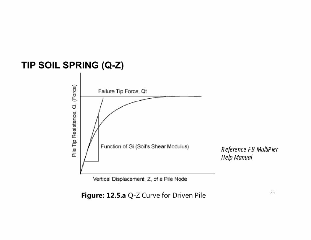
TIP SOIL SPRING (Q-Z)
25
Reference FB MultiPier Help Manual

AXIAL STIFFNESS CALIBRATION
26
= ?
3,000 kips 2,800 kips 2,500 kips
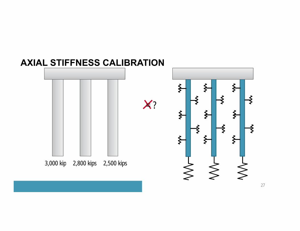
AXIAL STIFFNESS CALIBRATION
27
3,000 kips 2,800 kips 2,500 kips
= ?

AXIAL STIFFNESS CALIBRATION
28
3,000 kips 2,800 kips 2,500 kips
=
AXIAL STIFFNESS CALIBRATION
29
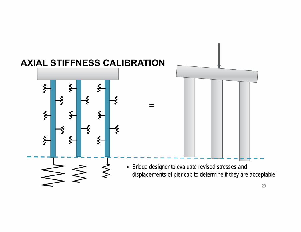
=
Bridge designer to evaluate revised stresses and displacements of pier cap to determine if they are acceptable

Shear modulus values are difficult to reliably estimate
Small strain stiffness measurements such as shear wave velocity testing needed
How to evaluate shear modulus of a soil plug at the toe of a displacement pile? The in-situ measurements are NOT representative of final stress state of soil.
Calibrate Q-Z springs such that individual max pile loads are limited to measured values
CALIBRATION OF TIP SPRINGS
30
Reference FB MultiPier Help Manual

AXIAL STIFFNESS CALIBRATION
31
Soften tip spring stiffness on piles with less axial resistance (red and green) until the modeled load on these piles is less than or equal to PDA measured resistanceo Iteratively revise shear modulus and ultimate tip capacity if needed
Pile with highest axial resistance (blue) will attract more load to compensate for softer springs at red and greeno Determine if revised increased load on this pile is acceptable
based on PDA measurements
Consequence: The cap will rotate and deflect, generatingdiffering stress distribution. Bridge designer must evaluateincreased cap stress and deformation.
Potential for insufficient driving resistance due to high pore pressures at end of initial drive
Restrikes often show higher skin friction, but can show less end bearing than end of initial drive
Decrease in end bearing could be due to relaxation or likely due to insufficient hammer energy to mobilize tip resistance with increased skin friction due to setup
Static load testing with indicator pile proved relaxation is not an issue
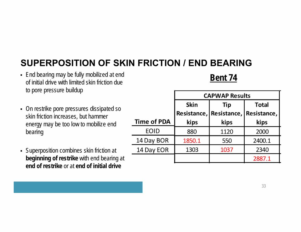
SUPERPOSITION OF SKIN FRICTION / END BEARING
32
SUPERPOSITION OF SKIN FRICTION / END BEARING
33
End bearing may be fully mobilized at end of initial drive with limited skin friction due to pore pressure buildup
On restrike pore pressures dissipated so skin friction increases, but hammer energy may be too low to mobilize end bearing
Superposition combines skin friction at beginning of restrike with end bearing at end of restrike or at end of initial drive
Bent 74

Minimum Tip Elevation Required Driving Resistance Geometrical Tolerance Pile Damage
TOPICS
34

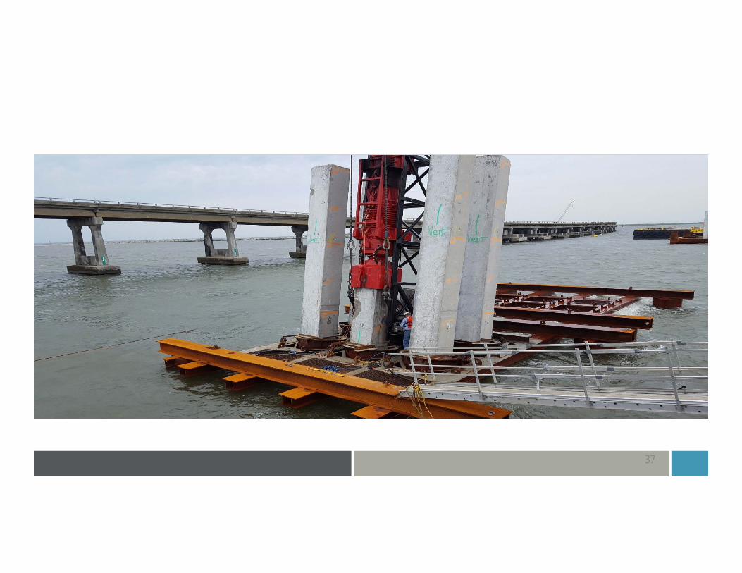
Large diameter battered piles in marine environments very difficult to position with tight geometrical tolerances
+/- 3 inches horizontal tolerance is typical
+/- 6 inches horizontal tolerance is more reasonable for large diameter piles
Large number of piles out of +/- 3 inch horizontal tolerance
PILES OUT OF HORIZONTAL POSITION OR BATTER ANGLE
35
Most piles ended up within +/- 6 inches of horizontal positiono Typical solution was to adjust reinforcing steel in cap and add ‘filler’ reinforcement so there no
large unreinforced gaps in the pile caps
FB MultiPier models typically updated with as-built pile positions and batter angleso Small adjustment in horizontal position makes little difference in pile loading and structure
behavioro Adjustment to batter angle tends to distribute pile load differently
Precast pile caps require tight geometric tolerance to fit, field adjustment is not possibleo Very stout frame used to position cylinder piles with precast caps
HORIZONTAL TOLERANCE - RESOLUTION
36
37

38

39

Minimum Tip Elevation Required Driving Resistance Geometrical Tolerance Pile Damage
TOPICS
40

Surficial spalling is typical on concrete piles and often does not affect pile integrity and can be repaired in place
Structural pile damage typically determined by change in cross sectional area of pile
Beta (BTA) method refers to %change in pile impedance in PDA records to evaluate damage
PILE DAMAGE
41
C (wavespeed) is known for the material type, E (modulus) is assumed constant, so a change in impedance suggests a change in A (cross sectional area)
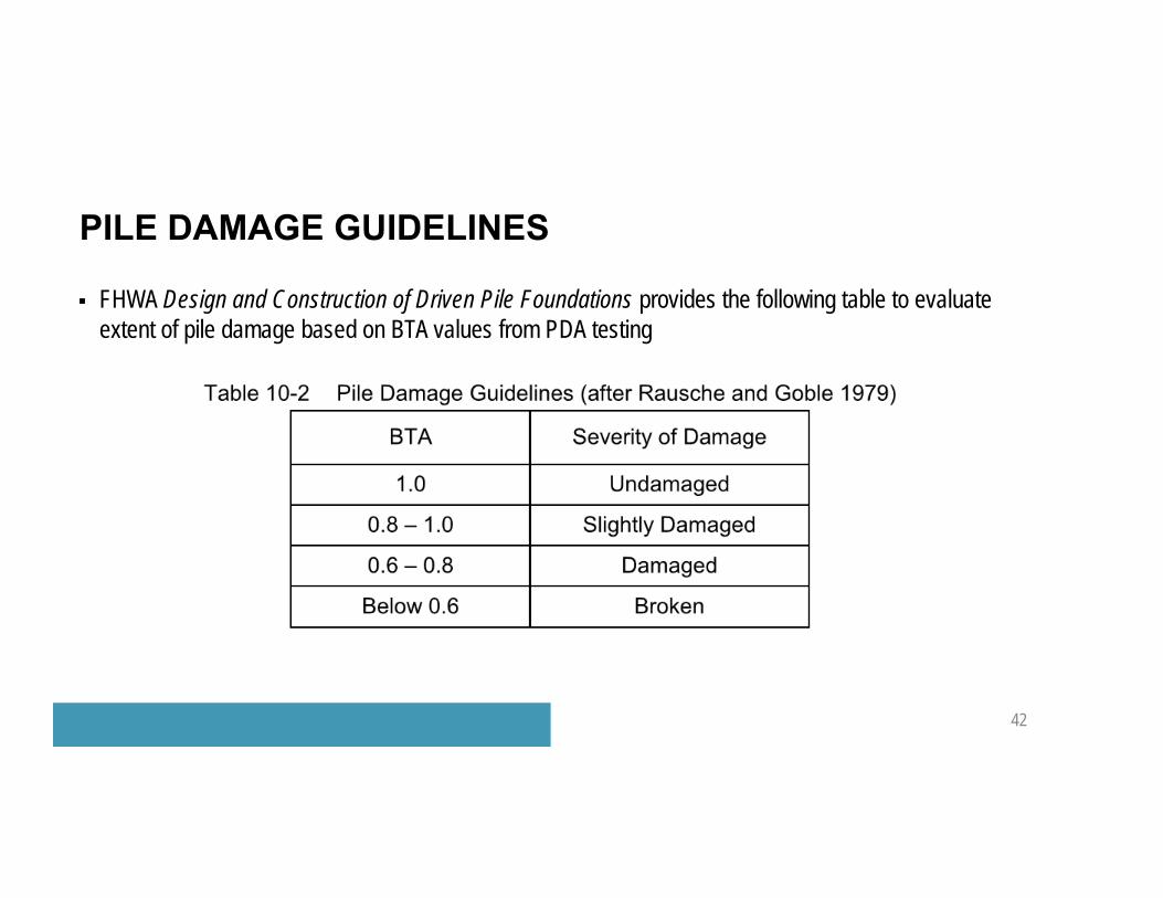
FHWA Design and Construction of Driven Pile Foundations provides the following table to evaluate extent of pile damage based on BTA values from PDA testing
PILE DAMAGE GUIDELINES
42
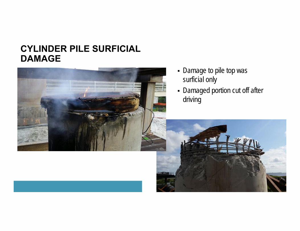
Damage to pile top was surficial only
Damaged portion cut off after driving
CYLINDER PILE SURFICIAL DAMAGE
43

CYLINDER PILE STRUCTURAL DAMAGE
44
Impedance change (damage) starting approximately 86.9 ft below grade and extending to approximately 113.7 ft below grade
Assume complete section loss due to 93.9% impedance reduction
No moment capacity below 86.9 fto Pile fixity achieved above 86.9 ft so no moment
capacity needed below this depth
Insufficient driving resistance due to pile damage, retrofit needed
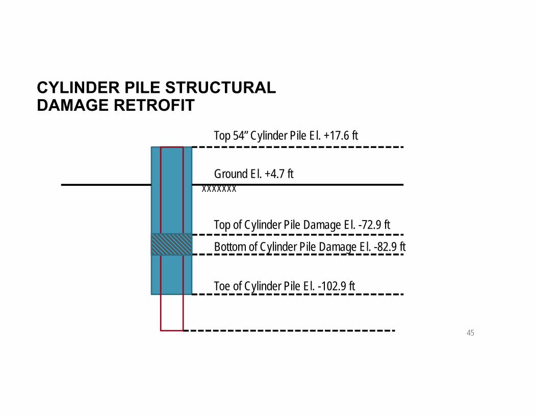
CYLINDER PILE STRUCTURAL DAMAGE RETROFIT
45
Top 54” Cylinder Pile El. +17.6 ft
Ground El. +4.7 ftXXXXXXX
Top of Cylinder Pile Damage El. -72.9 ft
Bottom of Cylinder Pile Damage El. -82.9 ft
Toe of Cylinder Pile El. -102.9 ft

CYLINDER PILE STRUCTURAL DAMAGE RETROFIT
46
Cylinder pile annulus cleaned out
Rollers used to guide 36” OD x ½” wall thickness open ended steel pipe pile inside cylinder pile
Steel pile vibrated to below the toe of cylinder pile then impact driven
Skin friction of cylinder pile above damage point superimposed with end bearing of steel pipe pile to provide adequate driving resistance

QUESTIONS?


