
F AD-A09B 689 ROYAL AIRCRAFT ESTABLISH04ENT FARNBOROUOIH (ENGLAND) F/S 21/8.1HIGH4-SPEED CItNATIC STUDIES OF WATER VAPORIZATION PH4ENOMENA IN-ETCU)NOW So W 6 GREISIAN
NSIFE RAE-T-8014..Rfl OR-7731 f lfl
I EN

- 1112
MIA- 1112 .
1111_L2 1.4 12jjj(1. Ifhj ~ .
MIRCP EOUINTS HR

0a UNUL fINTD
ROYAL AIRCRAFT ESTABLISHMENT
Technical ge * tr.144
HIGH7,,PEED CpINEMATICo;STUDIES OFWATER VAPORIZATION PHENOMENA
IN 5LECTROTHERMALJ-IYDRAZINE"TH RUSTER SI MULCATIONS.
by
w WG. Grenham
Procurement Executive, Ministry of Defence
Farn borough, H ants
-~ &pproed t-, public relecOe;
3 L

1
UDC 621.455.2 :546.171.5 :629.19.014.6 :536.422/423 :778.37 :533.6.071.311
4
ROYAL AIRCRAFT ESTABLISHMENT
Technical Report 80144
Received for printing 18 November 1980
HIGH-SPEED CINEMATIC STUDIES OF WATER VAPORIZATION PHENOMENA
I7 IN ELECTROTHERMAL HYDRAZINE THRUSTER SIMULATIONS
by
W. G. Grenham
SUMMARY
- Tests of prototype electrothermal hydrazine thrusters (EHTs), intended for satellite
attitude and orbit control, revealed anomalies in performance, attributed to problems in
vaporization. The process of vaporization was studied by high-speed cinematography, with
water substituted for hydrazine in models of the EHT. The results of the flow visualiza-
tion research are described, and it is concluded that Leidenfrost film-boiling effects
inhibited vaporization and affected the performance of the thrusters.
Departmental Reference: Space 589
Copyright
©
ControlZer HMSO London1980
-r1Bd DtubN_3TATtM kN U1Aprovod for public re1.G3;,
DIatrIbution Ur~it

2
LIST OF CONTENTS
Page
I INTRODUCTION 3
2 THE PHILOSOPHY BEHIND THE FLOW VISUALIZATION RESEARCH 5
2.1 The possibility of vaporization-rate dependence 5
2.2 The Leidenfrost phenomenon and the need for experimental study 6
2.3 The choice of water as a hydrazine substitute 7
2.4 The need for high-speed cinematography 7
3 FLOW VISUALIZATION EXPERIMENTS 7
3.1 Series I: injection on to heated gauzes 7
3.2 Series 2: partial simulation of prototype EHT 9
4 DISCUSSION OF RESULTS 12
5 PROPOSALS FOR FURTHER WORK 13
6 CONCLUSIONS 13
Acknowledgment 14
References 15
Illustrations Figures 1-24
Report documentation page inside back cover
AccessIon For
NTI' IDMr, T"RUInOn'v:-reod ,-1.
Juztificntion._
By__Dist 'ribut i°n/ _
Avsilabilit-v Codos'Avoil eia:ldor -
.. .. . ... ..t....S p....ec i { { { { {{ {
3
I INTRODUCTION
Electrothermal hydrazine thrusters (EHTs) are small, monopropellent propulsion
devices, currently under development for attitude and orbit control of satellites.
Thrusters used for attitude control normally operate in a pulsed limit-cycling mode, in
which the accuracy of the control system is dependent on the minimum impulse capability
It is necessary, therefore, within practical limitations, that the thrust level and
minimum pulse duration be made small. For example, a specification 2 for an EHT suitable
for use on a European connunications satellite called for a maximum thrust in the range
200-500 mN and a minimum impulse capability of 5 mN s, implying pulse durations possibly
as low as 10 ms. The EHT offers a potential advantage over existing low thrust pulsed
catalytic hydrazine thrusters in that these minimum impulses may be achieved at a higher3
exhaust velocity or specific impulse (ie, with greater propellent economy).
In the electrothermal hydrazine thruster the catalyst bed is replaced by a suitable
electrically powered heat exchanger. At the expense of some extra watts of electrical4
power, known limitations of catalytic thruster life (associated with catalyst erosion and
poisoning by the hydrazine decomposition products), which have been only partly overcome
by catalyst-pack heating, may be completely eliminated. So, with provision of suitable
long-life heaters, EHTs should be capable of delivering a much greater number of pulsesthan comparable catalytic thrusters.
To gain the greatest advantage from the use of EHTs (or for that matter from any
attitude and orbit control thruster) it is essential that the necessarily small impulse
values are achieved efficiently. Since the thrust coefficients of conventional convergent-
divergent nozzles have been shown5,6 to degrade with lower plenum pressures (due toboundary-layer growth at low Reynolds numbers) it is important that the rise and decay
times of the plenum pressure should be minimised. The nozzle will then operate close to
its design pressure, even for short duration pulses. The dwell time of the propellent in
- the decomposition chamber will vary with pressure so for optimum dissociation of the
propellent to avoid degradation of specific impulse, it is important that the thruster
exhibit stable behaviour without excessive pressure excursions.
In principle, to achieve short duration, stable pulses, the decomposition chamber vol-
ume must be minimised and within its confines, the propellent must be vaporized and decom-
posed as rapidly as possible. The ideal, overall decompositionrate is equal to the mass
flow rate of fuel into the decomposition chamber; under this condition the plenum pressure
would always be stable and the pulsed performance of the thruster would be optimised.
Unfortunately, for thrusters smaller than 500 mN, such a state has been extremely diffi-
cult to achieve. The conventional means of ensuring rapid decomposition or combustion,
employed in larger rocket motors7 and other combustion processes involving liquid fuels
8
is to atomise the propellent. In the EHT however normal atomising methods are not appro-
priate due to the imposition of a lower limit to injector dimensions to avoid blockage.
-An RAE prototype thruster is shown in Fig 1, attached to its propellent flow control
valve. It was designed to deliver a thrust in the steady state, of 200 mN at a supply
4
pressure of 1.4 MN/m2 (14 bar). In common with most, if not all, current hydrazine
thruster systems, there was a requirement that the EHT operate from an unregulated or
'blow-down' supply system, in which the pressure would fall predictably from 22 bar to
5.5 bar as the propellent was used during the useful life of the spacecraft.
The liquid monopropellent, anhydrous hydrazine, is delivered to an on-off electro-
magnetic flow control valve from a pressurised supply. The control valve shown attached9
to the thruster in Fig I is of a configuration developed by RAE9 . Valves of this type
have been manufactured by British Aerospace Dynamics Group, and have undergone qualifica-
tion testing at RAE 0 . The valve is operated by electrically energising the solenoid,
which retracts the armature, opens the valve, and allows hydrazine to flow through the
small bore injector tube (typically 0.125 to 0.15 mm diameter), and into the thruster
body. On switching off the solenoid current the valve closes under the action of a
return spring.
In these prototype thrusters which were used for ground level testing only, the
body was made of stainless steel (SI30B) and was heated electrically by means of a 6 W
ceramically insulated, sheathed element, coiled around and brazed to the outside of the
body.
The internal heat exchanger matrix consisted of a series of sixty 52 mesh platinum
*gauzes compressed to a length of 5 mm, with a single rigid mesh support, downstream, of
stainless steel. The gauze-pack heat exchanger served the purpose of supplying sufficient
thermal energy to vaporize propellent, and to initiate the decomposition reaction of
* hydrazine. Some of the thermal energy released by the exothermal decomposition was then
utilised to sustain the reaction.
With reference to Fig I, the volume between the injector tube exit and the gauze-
pack surface will be referred to as the 'head-space'. The internal diameter and the
length of the head-space, in this configuration, were both about 5 mm. Downstream of the
gauze-pack, a smaller 'tail-space' formed the plenum, leading to a conventional
4 4 convergent-divergent nozzle. The nozzle throat diameter was 0.45 mm, and the area
expansion ratio was 50:1 with a nozzle divergence half-angle of 15° . A dynamic measure
of plenum pressure was obtained and recorded by means of a suitable, low volume, pressure
transducer attached to the tapping into the tail-space. This gave an indication of the
internal performance of the thruster. ATests of the prototypes confirmed results reported by HSD for similarly configured
EHTs and showed that there seemed to be little problem in steady-state operation; however,
when operated in the pulsed mode, with pulse durations of I second or less, the perform-
ance of the thrusters was far from adequate. This was especially so during the first few
pulses of a train.
A 'typical' train of pulses is depicted in Fig 2. This demonstrates the form of the
starting transient and the fairly random pressure spiking effects which occurred. It can
be seen that the plenum pressure profiles exhibited some characteristic behaviour: the
pressure rose rapidly but then became inhibited or suppressed, before rising further to a
quasi-steady level on which the pressure spikes were superimposed. The characteristic dip

5
or levelling during the pressure rise will be referred to as the 'plateau region'. Long
duration pressure decays were also observed, though these are not evident from the Figure.
The form of the first pulse characteristic was influenced by the supply pressure
and by the initial holding temperature. Fig 3 shows an example of the variation in first-
pulse starting characteristic caused by varying the propellent supply pressure, while
Fig 4 illustrates the effect caused by variation of the initial holding temperature. It
may be noted from Fig 4 that there appear to be two plateau regions, the first becoming
increasingly significant as the temperature is raised, while the second, which is
separated from the first by a peak in the plenum pressure, is only significant at the
lower temperatures.
The flow visualization studies described in this Report were directed towards the
understanding of this behaviour. Experiments involving high-speed cinematography were
carried out to gain an improved knowledge of transient vaporization phenomena, so that
means of improving the pulsed performance of the prototype EHT might eventually be
derived.
2 THE PHILOSOPHY BEHIND THE FLOW VISUALIZATION RESEARCH
2.1 The possibility of vaporization-rate dependence
The behaviour of the prototype thrusters was inexplicable in all but a very general
sense; it was however realised that the anomalies described in section I must have
* resulted from one, or more, of the following:
* i) variations of the mass flow rate into the decomposition chamber;
(ii) fluctuations in the vaporization rate of propellent within the decomposition chamber;
(iii) fluctuations in the decomposition rate of vaporized propellent within the thruster.
To determine a means of improving the design it was necessary to study, and hopefully to
isolate, the short-lived phenomena that occurred within the thruster. The alternative, of
performing a great number of empirical tests while varying particular thruster parameters
4 - or configurations, was considered to be inadequate. Even if an improvement were achieved
by this entirely empirical method, sufficient understanding of the reasons would not be
available to aid scaling for different thrust levels.
It was reasoned that, since thermal decomposition of the propellent occurs mainly in12the vapour phase , although undoubtedly influenced by the temperature and the geometry of
the thruster decomposition chamber, the decomposition reaction was likely to be
vaporization-rate dependent, especially as the injector was not designed to atomise the
propellent, and therefore a study of vaporization phenomena would be worth while. It is
well known 13 that heat transfer rates during film-boiling are drastically lower than those
during nucleate-boiling, and a study of some of the literature concerning the Leidenfrost
phenomenon 14 ,15 suggested the possibility that propellent vaporization, and hence
decomposition rate, was reduced by film-boiling effects.
6
2.2 The Leidenfrost phenomenon and the need for experimental study
The Leidenfrost phenomenon was named after the 18th century medical doctor who first
studied it 16 . Traditionally it is concerned with the film-boiling of small liquid masses
on hot surfaces.
As the temperature of a heated surface is raised above the saturation temperature of
the liquid (the 'boiling point' if the experiment is performed at normal atmospheric
pressure), the vaporization rate of a droplet placed on the surface increases during what
is generally termed the nucleate-boiling r4gime. Under this condition the liquid wets the
surface and there is good thermal conduction into the liquid from the surface. Vapour
generation is from nucleation sites, ie small imperfections in the heated surface. At
higher temperatures, however, when the change from nucleate to film-boiling occurs, the
vaporization rate falls dramatically. At temperatures above the transitional zone heat
transfer from the plate is such that vaporization occurs across the whole interface, with
the result that the droplet may be suspended above the surface on a cushion of vapour.
The result is a reduction in the rate of heat transfer to the liquid. The lowest value of
surface temperature at which stable film-boiling of a droplet is observed under a given14
set of experimental conditions is called the Leidenfrost point and coincides with the
minimum heat transfer condition.
Fig 5 shows the form of the vaporization rate/excess temperature characteristic for
* water. The curve is based on experimental data on the variation of total vaporization
time of uniform droplets with excess temperature presented in Ref 17. The excess tempera-
ture AT is defined as the difference between the local temperature T of the plate,p
and the saturation temperature T of the liquid such that5
AT = T - T
p s
Fig 5 may be compared with a similar curve showing heat flux against excess temperature
for boiling on a platinum wire, presented in Ref 13 and elsewhere. Although no data was
available for hydrazine, other liquids (including flamnnables such as benzene, n-octane,
kerosene and ethanol) are known to demonstrate a similar form of behaviour to that of14,17water . The gradual rise in heat transfer rate after the Leidenfrost transition is
caused by the increase of radiant heat transfer to the droplet with increasing surface13
temperature
Under a given set of conditions the initial size of the droplets appears to have
little effect on the measured Leidenfrost point 14 . The method of deposition of a droplet
*onto a surface does, however, have a marked effect on the observed Leidenfrost point and
on the heat transfer rates. It has been shown 15 that for oblique incidence on to flat
plates, the normal component of velocity is the important factor. While it is known that
good repeatability can be achieved in experiments concerning Leidenfrost film-boiling on14flat plates, there is no unique value of the Leidenfrost point for a given liquid . It
would appear that this may be accounted for by differences in experimental technique,
surface texture, and even between different experimenters using the same apparatus.
Given these uncertainties concerning Leidenfrost phenomena when confined to flat
plates it was clear that some experimental work would be needed before reliable conclusions

7
could be reached about propellent vaporization in EHTs. Tests were proposed, therefore,
in which the vaporization phase of the propellent reaction was isolated by the substitu-
tion of a suitably inert fluid and as the most convenient method of differentiating
nucleate- and film-boiling was by visual observation, ie by the 'wetting' or 'non-wetting'
of the heated surfaces, it was decided to use a flow visualization technique.
2.3 The choice of water as a hydrazine substitute
Water was chosen as a suitable fluid for the tests as it had a number of advan-
tages. Firstly, its total non-flamability meant that the vaporization effects could
be isolated by the exclusion of decomposition and/or combustion. Secondly, with the
possibility of combustion removed and in the absence of any toxicity problem the experi-
ments could be carried out in atmosphere under normal laboratory conditions, which meant
that the experimental requirements could be greatly simplified. Thirdly, many of the
physical properties of hydrazine and water are similar at least to a first approximation.
The most obvious of these is the boiling point, that of anhydrous hydrazine at normal
atmospheric pressure being 113.5 0 C which is close to that of water. They are both colour-
less liquids with low vapour pressures. Their respective densities, surface tensions,
viscosities, and specific heat capacities are similar. A major difference in relevant
physical properties between the two fluids, however, apart from their chemical differences
and flammabilities, is between their latent heats of vaporization. Water, possessing a
6higher value of latent heat would, if exposed to the same conditions as hydrazine, require
more thermal energy to effect a phase change. It was possible, however, to take this into
account in interpreting results.
2.4 The need for high-speed cinematography
In designing the experiments it was realised that the processes of injection,
vaporization and exothermal decomposition were highly interrelated: in steady-state
operation a proportion of the thermal energy derived from the decomposition reaction was
required to be fed back to sustain vaporization. This was because the sensible heat in
4" the thruster body was insufficient to sustain vaporization, and the steady electrical
power supplied to the thruster heater was of the order of a twentieth of that required for
continuous vaporization. Dynamic tests with water therefore would have most relevance to
the starting transient, when vaporization would depend primarily on the thermal energy
stored in the thruster body and gauze matrix.
Since the events to be studied were transitory phenomena of short duration, a visual
recording technique employing high-speed cinematography was necessary.
3 FLOW VISUALIZATION EXPERIMENTS
3.1 Series 1: injection on to heated gauzes
The object of the first series of flow visualization tests was to establish whether
film-boiling effects could be observed in the behaviour of water injected on to heated
gauzes and, if so, to ascertain the temperature rdgime in which they became significant.
This was to be done by filming the transient behaviour of water injected towards a
suitable gauze-pack, the gauzes being heated over a range of initial temperatures.4 -

* 8
The apparatus consisted of a pack of five stainless steel gauze; as shown,
diagrammatically, in Fig 6. The gauzes were clamped at either end to thermal sources to
which electrical heaters were attached. The starting temperature for each test was
determined from a thermocouple spot-welded to the lower gauze. The injector had a bore of
0.15 mm diameter and was mounted with its exit plane approximately 4.5 mm from the upper-
most gauze. Water was delivered to the injector from a pressurised supply, via a suitable
electromagnetic valve.
The photographic set-up for the experiment is shown in Fig 7. The injector and
gauzes were back-lit using a tungsten filament bulb and an optical condenser. Some pre-
test runs were carried out and established that a filming speed of 5000 frames/second was
suitable. With this framing rate, the effects of single pulses of lOOms duration could be
accommodated on 100 feet of 16 mm cind film, allowing for acceleration time of the film in
the camera, prior to the event. A time resolution of 0.2 ms was therefore achieved. An
accurate measurement of elapsed time was obtainable from the processed film record as a
time-base unit was employed giving I ms time marks on the edge of the film. An event mark
was incorporated, being triggered simultaneously with the valve driving unit. The valve
* was triggered from the camera once the pre-selected running speed had been achieved.
*A series of test runs was performed within a gauze initial temperature range of
293-770 K, with single pulses of 100 ms duration. The steady-state flow rate through the
capillary bore injector was 0.17 ml/s. A limit imposed by the thermal losses from theC
experiment precluded tests at temperatures greater than 770 K.
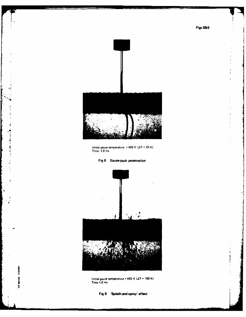
Figs 8 to 11 show some selected still frames obtained from the processed high-speed
cind films. The times quoted relate to the instant of fluid emergence from the injector
tip and therefore exclude valve operating and injector transport delays. The films showed
* that with moderate initial temperatures, between 373 K (1000 C) and 473 K (2000C), or with
excess temperatures in the range 0-100 K the liquid stream penetrated the surface of the
gauze-pack and boiling was contained within the gauzes (Fig 8). A quenched area surround-
ing the impact zone supplied liquid to the hot periphery by a wicking action, created bythe capillary forces active within the matrix. With an initial gauze-pack temperature of
*482 K, or an excess temperature of approximately 110 K, a short duration 'splash and
spray' effect was observed (Fig 9), rapidly followed by quenching of the tPget zone.
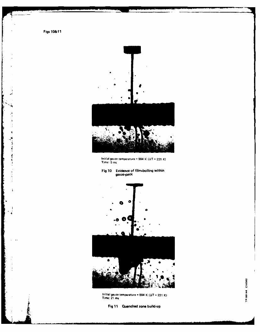
When the gauze-pack initial temperature was between 473 and 573 K (e with a tempera-
ture excess AT of 100-200 K), film-boiling effects became apparent. With the gauze-pack
initially at temperatures greater than 590 K (AT > 220 K), the impinging stream of fluid
created a splash and spray containing small spheres of liquid (Fig 10). This was followed
*by the formation of a quenched zone and a quantity of liquid began to accumulate, attached
to the lower surface of the gauze-pack (Fig 11). Small droplets of liquid emerged from
the upper and lower surfaces of the matrix outside the quenched zone. From a comparative
study of the films it could be seen that the width of the quenched zone decreased with
increase of temperature (Fig 12). This, and the fact that the amount of liquid apparentlyrejected by the gauze above the target zone also increased with temperature, indicatedthat as the gauze-pack temperature of an EHT rose, one might expect a greater accumulation
of liquid in the head-space. The fact that more liquid was observed to penetrate through

9
the gauzes as the initial temperature rose was not taken as necessarily indicating that
the penetration depth into an EHT gauze-pack would increase, since the presence of further
hot gauzes beneath the surface layers would affect the penetration. The duration of the
initial splash and spray effects increased with rising start temperature, as did the
average size of the droplets produced.
It was noted that, over the temperature range covered, the liquid stream was not
rejected entirely by the gauze-pack; a quenched zone was produced, at the periphery of
which film-boiling was seen to be active, evident from the presence of small liquid
spheroids which did not wet the gauze filaments on impact, but deflected off the sur-
face with no measurable change in size. Thus Leidenfrost film-boiling effects were
observed and it was judged that these might be capable of playing a significant role in
the operation of the prototype design of electrothermal hydrazine thruster.
It was decided that a more refined experiment should be designed, in order to give a
more realistic representation of the prototype EHT and so that a greater range of gauze
initial temperatures could be studied. In particular it was of interest to record and
observe how the liquid droplets rejected from the gauze-pack behaved within the head-space,
especially when subjected to interdroplet collisions and to impact with the head-space
* walls.
3.2 Series 2: partial simulation of prototype EHT
x It can be seen from the schematic diagram (Fig 13) that the model used for the
series 2 tests was more representative of the prototype thruster. The injector tube
was identical in bore and external diameter to that used in the prototype. The head-
space walls, while being open on two opposing faces to allow filming, were represented
by plane surfaces. These were machined at the ends of the two heat sources which
replaced the body of the thruster. The sources were heated electrically and were
linked by a stainless steel plate which was used also to locate the injector. The gauze-
pack, which incorporated thirty platinum gauzes, was identical in mesh and wire diameter
4 1 to that used in the prototype EHTs (52 mesh x 0.1 m diameter wire) and was clamped to
the two heat sources. The internal cross-section in the plane of view was approximately
the same size as the prototype EHT design. Since the model was open, the build-up of
pressure in the head-space was precluded.
By simulating the thruster walls and their attachment to the injector, this model
could be used to simulate the vaporization phase of the first pulse of a train, where the
injector/head-end joint would be at an elevated temperature, and where some degree of
vaporization in the injector could occur.
The tests were performed with a similar photographic set-up as described for the
* series I tests (see Fig 8). The pulse durations filmed were again 100 ms, and the filming
speed of 5000 frames/second, established as suitable for the first series, was main-
tained in order to resolve the transient events. An event mark and timing marks at I ms
intervals were incorporated, appearing at the edge of the film.
A series of eight test runs was performed over a gauze-pack initial temperature
range of 300-1000 K. Temperatures were measured by thermocouples spot-welded to the

10
platinum pack and to the heat sources in the positions shown (Fig 13). The steady-state
volumetric flow rate through the injector was again 0.17 ml/s.
Some of the results, including frames extracted from the processed high-speed cing
film of the series 2 tests, are shown in Figs 14 to 24. For the purpose of the discus-
*sion, the effects are divided into four phenomena, which, while they may have overlapped
chronologically on the filmed record, will be treated separately. The aspects are:
(i) vaporization within the injector;
(ii) formation of a quenched zone in the gauze-pack;
(iii) growth of the quenched zone; and
(iv) droplet collisions.
(i) Vaporization within the injector
During the lower temperature runs there was no evidence of vaporization within the
injector; however, as the initial temperatures were raised the effects of vaporization in
the injector became more pronounced. With a starting temperature (of the heat sources)
of 504 K (or an excess temperature of 131 K), ie within the expected transition region
(see Fig 5), a spray was visible from the tip of the injector for 1-2 ms (Fig 14). As the
*starting temperature was raised, the duration of the spray from the injector increased.
The spray appeared to be composed of a mixture of vapour and atomised liquid. Collapse of
the spray cone as the injector quenched was characterised as shown in Fig 15 by a central
core of liquid impinging on the gauze-pack, the core being surrounded by a divergent
stream of vapour. The change to this short-lived state will be termed the 'first flow
transition'. Although the dynamic flow rate was not recorded (due to the unavailability
of a flowmeter with suitable dynamic response), it was qualitatively apparent that the
mass flow was inhibited during the vaporization phase. It may also be reasoned that
boiling in the tube reduced the mass flow rate, since there would have been a local pres-
sure increase resulting in a reduction of pressure gradient within the liquid. Total
quenching of the injector followed, with the apparent establishment of full flow and the
4 time at which this was determined to have occurred will be termed the 'second flow tran-
sition'. The duration of the vaporization/atomisation within the injector, ie the time to
the second flow transition, increased as the initial body temperature was raised. This
duration of vaporization/atomisation has been plotted in Fig 16. It can be seen that the
two flow transitions described above became more defined at higher initial temperatures,
as the time to the first flow transition and the time between the two flow conditions both
increased with temperature. If the different latent heats of vaporization of water and
hydrazine are considered it may be expected that the vaporization times would be greater
for hydrazine, even in the absence of any decomposition.
(ii) Formation of a quenched zone
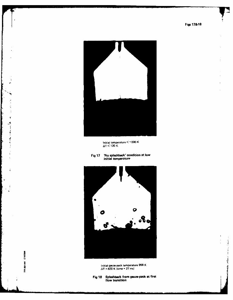
For gauze-pack initial excess temperatures below 120 K the behaviour was much the
same as that described by the series I test results: the impinging liquid stream rapidly
quenched the gauzes at the target zone, to a temperature below the boiling point of the
liquid, and the stream was taken up rapidly by the gauze-pack without splashback (see
Fig 17). The liquid was then wicked towards the periphery where, for heat source 41

temperatures of 373-493 K (AiT = 0-120 K), nucleate-boiling was observed at the heat source
wall.
As the initial excess temperature, AT , was raised above 120 K, the collapse of the
partially vaporized spray (described above) as the injector quenched, was followed or at
higher temperatures accompanied by some splashback from the gauze-pack surface (Fig 18).
At the higher end of the explored temperature range, some coalescence of the mist into
droplets occurred on impact with the surface of the gauze-pack even before the first tran-
sition of injector flow had occurred (Fig 19). The droplets formed did not wet the
surface of the pack. After the second injector flow transition (and sometimes between the
two transitions, which were described earlier), a definite quenched zone appeared at the
impact area. The size of this zone at the surface of the pack, and its variation with
elapsed time could be observed from the film because of the emission of small globules of
liquid, from its periphery, into the head-space. This has not been illustrated here as it
cannot be shown adequately in a still photograph.
(iii) Growth of the quenched zone
Initial growth of the quenched zone was beneath the surface of the gauze-pack,
adjacent to the target area. This was followed by the build-up of a liquid blob on the
surface of the pack (Fig 20). The reason for this partial rejection from the gauze-pack
was considered to be due to the overcoming of the capillary forces, by the local pressure
of steam generated by film-boiling (or mixed film- and nucleate-boiling) within the inter-
stices of the gauze matrix. The liquid-quenched zone expanded until the thermal gradient,
across the gauze matrix between heat sources and liquid, was such that film-boiling would
occur (providing the heat-source temperature remained sufficiently high). Thus, with a
quenched zone within the pack growing very slowly (relatively) and vaporization inhibited
by film-boiling, as the inlet flow continued the liquid blob grew out from the surface of
the pack (Fig 21), sometimes rotating or oscillating about the impinging jet of liquid.
The free droplets in the head-space in Figs 20 and 21 were emitted from the non-quenched
surface of the gauze-pack.
The width of the quenched zone increased with time until it filled the surface of
the gauze-pack. As the liquid reached the edges of the pack (Fig 22) it was repelled by
the heat-source walls in typical film-boiling style, and large globul of liquid were
often ejected into the head-space from the periphery of the pack.
(iv) Droplet collisions
It has been indicated above that there were three sources of free droplets in the
head-space: those generated by the coalescence of mist above the gauze-pack; those genera-
ted by film-boiling effects within the gauze-pack and which emerged into the head-space
from the non-quenched area of the gauze-pack surface; and those which were created as the
quenched zone spread to, and was rejected by, the body walls. Once generated, all these
droplets were subject to random collisions with the head-space walls, other droplets, the
liquid stream, the quenched zone, or the non-quenched gauze surface.
It was noted that the Leidenfrost point for the head-space walls was in the region
- of AT - 120 K , ie T = 490 K . At temperatures below this value those few droplets that

12
were observed vaporized rapidly by nucleate-boiling when in contact with the head-space
walls. At higher temperatures, the droplets failed to wet the surface on collision with
the walls, and the heat transfer to the droplets was minimal. This was demonstrated by
the fact that the majority of droplets rebounded from the head-space walls with no measur-
able decrease in apparent size and usually with little variation in speed. These droplets
were in effect subject to elastic collisions with the walls.
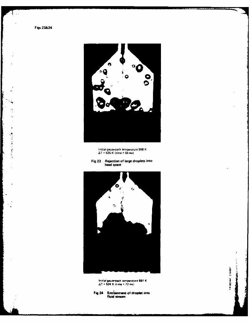
The presence of larger droplets in the head-space as the initial temperatures were
increased was accounted for partly by the rejection of large droplets from the target zone
of the gauze-pack (Fig 23), but it was also affected by the quantity of smaller droplets
present. That is, the greater the number of small droplets, the higher the probability of
interdroplet collisions leading to amalgamation into larger droplets.
Collision of a droplet with the established liquid stream emerging from the
injector usually resulted in the droplet being entrained by the stream due to surface
tension effects. It was possible, however, if it had sufficient momentum, for a droplet
to cause a temporary disruption of the stream. Fig 24 illustrates both these effects.
A droplet is being entrained by a fluid stream previously disrupted by collision of
another droplet.
Droplets in collision with the quenched zone were taken up by the zone. As the
quenched zone spread with time across the surface of the gauze-pack there was an increas-
ing probability of these collisions occurring, and thus a tendency for all the non-
vaporized liquid to accumulate at the quenched zone. Collisions of droplets with the non-
quenched surface of the gauze, ie at a temperature greater than the local Leidenfrost
point, were subject to film-boiling and were therefore rejected from the pack.
4 DISCUSSION OF RESULTS
The tests and the results described yielded a much greater understanding of the
physical processes involved in propellent injection and vaporization in the prototype EHT
configuration.
4 (i) Using water, film-boiling effects were observed with the head-space wall temperature
as low as 490 K 'e with an excess temperature, AT , of about 120 K). They became sig-
nificant at a temperature in excess of 520 K (AT > 150 K) and became increasingly
pronounced as the initial temperature was raised further. Thus the Leidenfrost effect was
seen to play an important role in inhibiting the vaporization of propellent within the
thruster body.
(ii) The duration of splashback from the gauze-pack surface increased with initial
. ' temperature, demonstrating again the effects of film-boiling, which was by definition
maintained until the local gauze temperature was below the Leidenfrost point. Nowhere in
the range of temperatures explored however was the liquid stream totally rejected by the
gauze-pack surface; a quenched zone was always formed.
(iii) Depth of penetration of the gauze-pack decreased with increasing gauze-pack tempera-
ture, associated with a greater build-up of liquid in the head-space and delayed lateral
penetration within the matrix. 4

13
(iv) Vaporization within the injector also appeared to play a significant role, by
reducing the initial mass flow into the thrust chamber. The duration of this vaporization/
atomisation increased with temperature. It was thought that film-boiling, possibly aided
by a change to turbulent flow, provided the mechanism by which the water was atomised
within the injector. Although this inhibited the mass flow during the period over which
it occurred, the suggestion was made that if the injector could be made to operate contin-
uously in this mode at an increased mass flow rate, it would provide a novel means of
achieving atomisation. However, the suggestion was discarded in connection with the
prototype EHT due to the wide range of flow rate over which the thruster was expected to
operate in the blow-down mode, combined with the complexities involved in designing the
device to operate at various duty cycles from the pulsed mode to steady-state operation.
5 PROPOSALS FOR FURTHER WORK
On completion of the flow visualization studies which have been described, it wasclear that further research would be required.
(i) In order to ensure that the vaporization effects were valid in the presence of
thermally decomposing hydrazine vapour, the flow visualization studies should be extended
to incorporate the exothermal decomposition phase. This would involve the design and
* manufacture of a suitable see-through electrothermal hydrazine thruster, whose internal
*performance would closely resemble that of the prototype EHT;
(ii) Assuming the validity of the flow visualization studies already performed using
water, alternative thruster configurations should be identified and the high-speed
cinematographic studies should be extended to their transient vaporization behaviour;
(iii) Means of active or passive cooling of the injector should be explored to investi-
gate the effect of injector temperatures on thruster response.
At the time of writing research has been continued in the directions indicated, and
the results, which are extremely promising, will be the subjects of further reports. In
4 , particular some high-speed cinematographic results obtained with hydrazine have been
presented briefly in Ref 20.
6 CONCLUSIONS
Certain anomalous behaviour of a prototype electrothermal hydrazine thruster has
been described.
Some high-speed cinematographic studies were made of transient vaporization
phenomena using water within a model of the EHT.
The conclusion was drawn that film-boiling effects similar to those described by
the Leidenfrost phenomenon were likely to occur within the decomposition chamber of the
prototype EHT, and these were likely to result in inhibition of vaporization and affect
the decomposition rate of the propellent.

14
It was also indicated that complete, or even partial, vaporization of the propellent
within the injector could have a deleterious effect-on the starting transient of the
prototype thruster.
A need for further experimental work was identified.
Acknowledgment iThe author would like to express his gratitude to those members of Instrumentation
and Trials Department at RAE, who assisted with the photographic work, especially Mr G.
Beevers whose high-speed cinematography recorded all the transient phenomena described.
4
15
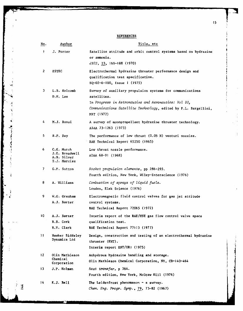
REFERENCES
No. Author Title, etc
I J. Porter Satellite attitude and orbit control systems based on hydrazine
or amnonia.
JBIS, 23, 169-188 (1970)
2 ESTEC Electrothermal hydrazine thruster performance design and
qualification test specification.
EQ-02-6-100, Issue 1 (1975)
3 L.B. Holcomb Survey of auxiliary propulsion systems for communications
D.H. Lee satellites.
In Progress in Astronautics and Aeronautics: Vol 33,
Comnunications Satellite Technology, edited by P.L. Bargellini,
MIT (1972)
4 .J. Russi A survey of monopropellant hydrazine thruster technology.
-AIAA 73-1263 (1973)
5 B.P. Day The performance of low thrust (0.05 N) venturi nozzles.
RAE Technical Report 65250 (1965)
6 C.K. Murch Low thrust nozzle performance.J.E. Broadwell -91 (1968)
- A.H. Silver AIAA 68
T.J. Marcisz
7 G.P. Sutton Rocket propulsion elements, pp 286-295.
Fourth edition, New York, Wiley-Interscience (1976)
8 A. Williams Combustion of sprays of liquid fuels.
London, Elek Science (1976)
4 9 W.G. Grenham Electromagnetic fluid control valves for gas jet attitude
A.J. Barter control systems.
RAE Technical Report 72065 (1972)
10 A.J. Barter Interim report of the RAE/HSE gas flow control valve space
R.B. Cork qualification test.
R.V. Clark RAE Technical Report 77113 (1977)
11 Hawker Siddeley Design, construction and testing of an electrothermal hydrazineDynamics Ltd thruster (EHT).
Interim report EHT/IR (1975)
12 Olin Mathieson Anhydrous hydrazine handling and storage.ChemicalCorporaln Olin Mathieson Chemical Corporation, NY, CD-140-464Corporation
13 J.P. Holman Heat transfer, p 364.
Fourth edition, New York, McGraw Hill (1976)
14 K.J. Bell The Leidenfrost phenomenon - a survey.
Chem. Eng. Progr. Symp., 79, 73-82 (1967)

16
REFERENCES (concluded)
No. Author Title, etc
15 F.K. McGinnis III Individual droplet heat transfer rates for splattering on
J.P. Holman hot surfaces.
Int. J. Heat Mass Transfer, 12, 95-108 (1969)
16 J.G. Leidenfrost De aqua communis nonnullis qualitatibus tractatus.Duisburg on Rhine (1756)
Relevant part available as "On the fixation of water by diverse
fire", translated by C. Wares.
Int. J. Heat Mass Transfer, 9, 1153-1166 (1966)
" 17 B.S. Gottfried The Leidenfrost phenomenon: film-boiling of liquid droplets on
C.J. Lee a flat plate.
K.J. Bell Int. J. Heat Mass Transfer, 9, 1167-1187 (1966)
18 A.J. Barter Electrothermal hydrazine thruster flow visualisation study.
-4 In Proceedings of AOCS Conference, ESA SP-128, pp 471-477 (1977)
Reports quoted are not necessarily available to members of the public or tocommercial organisations.
4 4

Fig I
EE
C e Ln CL
M~o EeCL*
14
I CL
0.0
C
a0
V 0
:33In
44
060
EDE
0

Figs 2&3
4
Thruster3plenum
press ure
1' 20
q 15
number
Time (ins)
Fig 2 Typical train of pulses, obtained with prototype thruster EFI/4. (Fuel supply pressure1.8 MI'tm 2. Initial holding temperature 740 K. Duty cycle 20%)
1.0
0.8 -SuppLy pressure
Thruter .6 -1.4 MN m-2
plenum 061.5 MN m-2
pressure(MN m-2 1 0.5 700 KN m-2
0.2 - 350 KN m- 2
0 500 1000Time (ins)
Fig 3 Effect of fuel supply pressure on starting characteristic of prototype thruster EFI/3.(Initial holding temperature constant at 750 K)

Fig 4
3
Thruster 2.plenum
-A pressureI(MN m-2 )1
0
Nominal 80
temperaturv,65at start of puLse (K) 6 0 50 10
Time (ins)
K Fig 4 Effect of initial holding temperature on starting characteristic of prototypethruster E F 14A (Fuel supply pressure constant at 1.4 MN m'2 )
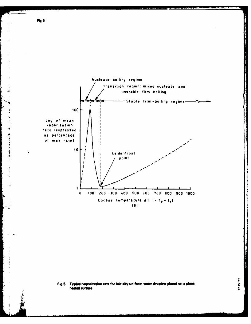
Fig 5
Nucleate boiling regimeTransition region: mixed nucleate and
unstable film boiling
-______Stable film -boiling regime-'--m
100
Log of meanvaporizatiton
rate (expressedas percentageof max rate) 4
10 II Leidenfrost--
I ~~~point - - - - - -
0 100 200 300 400 500 COO 700 800 900 1000
Excess temperature AT (2TP - Ts)(K)
4
Fig 5 Typical vaporization rat for Initially uniform water droplets placed on a plaeheatd surfae

Fig 6
4
Electromagnetic
Water from flow-control Valveprosu~trised supply
Field of view Thermalof cmerainsulation
* r4
Hete a E Qaa
Gauze -pack Thiermocouple
4
Fig 6 Schemnatic diagram of Soria 1 apparatus
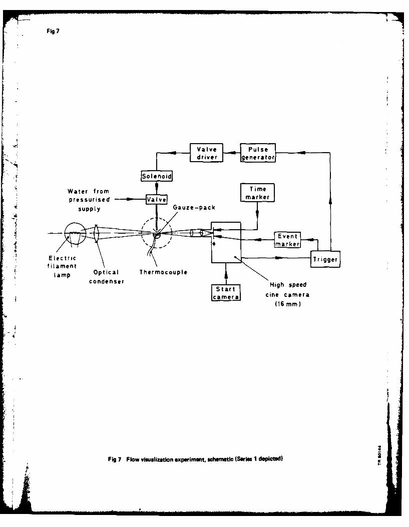
Fig 7
Optical o Throcopl
markecmr
4 m16rme)
Fletgi 7Tlriggeroneprmet chmtc(Sis1deitdfilamen
Opia hem cul
Figs 8&9
Initial gauze temperature 406 K (AT 33 K)Time: 1.0ms
Fig 8 Gauze-pack penetration
4
Initial gauze temperature =482 K (AT- 109 K) -
Time 1.0 ms
Fig 9 'Splash-and -spray' effect
Figs 10&11
A
011111111
Initial gauze temperature =594 K (AT =221 K)Time: 5 ms
Fig 10 Evidence of film-boiling withingauze-pack
4
Initial gauze temperature =594 K (AT - 221 K)0Time: 21 ms
il Fig 11 Quenched zone build-up

Fig 12
6
NT 1 594 K
5
*Width of
quenched 4
zone T=73
++
4 1
0 25 50 75 100
Time (ins)
3 j Fig 12 Variation of width of quenched zone with time and temperature

Fig 13
Water ___from_ flow-control valvepressurised supply
InjctoHedspc
Thermal----------- .insulation
Fied f vew Thermocouples Gauze - packof camera
Fig 13 Schematic diagram of Seris 2 apparatus

Figs 14&15
-i
Initial body temperature = 504 K (AT = 131 K)Time: 1 ms
Fig 14 Initial vaporization in injector
ao Initial body temperature 833 K (AT = 460 K)Time: 18 ms
Fig 15 First flow transition

Fig 16
60L0 First flow transition
50 - Second flow transitionTime to flow 0-to
transition 4
mis) 30
20
10
0 100 200 300 400 500 600 700 800Excess temperature AT C T - Ts
deg K)
4
Fig 16 Injector quenching characteristics for Series; 2 test
Figs 17&1
initial temperature <'-390 KAT< <120 K
Fig 17 'No splashback' condition at lowinitial temnperature
2 Initial gauze-pack temperature 998 KIt A~T -=625 K (time - 27 ins)
Fig 18 Splashbaok fromn gauze-pack at firstflow transition

Figs 19&20
Initial gauze-pack temperature 998 KAT = 625 K (time = 15 ins)
ff
-..
Fig 19 Coalescence of propellent mist intodroplets on impact with gauze-packprior to first flow transition
U
It r
Initial gauze-pack temperature 698 K i
AT -325 K (time -15 ms)I-
Fig 20 Build-up of liquid blob attachedto quenched zone

Figs 21&22A
Initial gauze-pack temperature 698 K/ AT = 325 K (time = 22 ins)
Fig 21 Growth of liquid blob
Initial gauze-pack temperature 897 Kg AT = 524 K (time = 95 mns)
Fig 22 Wave motion in liquid blob as quenchedzone approaches heed space walls
Figs 23&24
AT=62 (ie 0 ms)
00
4.
Initial gauzepack temperature 98 KAT 624 K (ibme 72 50is)
Fig 2 REjetiwnt ofag droplets intohead space
REPORT DOCUMENTATION PAGEOverall security classification of this page
UNCLASSIFIED
As far as possible this page should contain only unclassified information. If it is necessary to enter classified information, the boxabove must be marked to indicate the classification, e.g. Restricted, Confidential or Secret.
1. DRIC Reference 2. Originator's Reference 3. Agency 4. Report Security Classification/Marking(to be added by DRIC) Reference
RAE TR 80144 N/A UNCLASSIFIED
5. DRIC Code for Originator 6. Originator (Corporate Author) Name and Location
7673000W Royal Aircraft Establishment, Farnborough, Hants, UK
5a. Sponsoring Agency's Code 6a. Sponsoring Agency (Contract Authority) Name and Location
N/A N/A
7. Title High-speed cinematic studies of water vaporization phenomenain electrothermal hydrazine thruster simulations
7a. (For Translations) Title in Foreign Language
f, t7b. (For Conference Papers) Title, Place and Date of Conference
8. Author I. Surname, Initials 9a. Author 2 9b. Authors 3,4 .... 10. Date Pages Refs.November[ 2]1Grenham, W.G. 1 r 32 1
11. Contract Number 12. Period 13. Project 14. Other Reference Nos.
N/A N/A Space 589
15. Distribution statement(a) Controlled by- Head of Space Departument, RAE
(b) Special limitations (if any) -
16. Descriptors (Keywords) (Descriptors marked * are selected from TEST)Electrothermal hydrazine thruster. Satellite attitude and orbit control.Vaporization. Leidenfrost effect. Film-boiling.Hi h-speed cinematography. Flow visualizatioi.
17. Abstract
Tests of prototype electrothermal hydrazine thrusters (ERTs), intended forsatellite attitude and orbit control, revealed anomalies in performance,attributed to problems in vaporization. The process of vaporization was studiedby high-speed cinematography, with water substituted for hydrazine in models ofthe ET. The results of the flow visualization research are described, and it isconcluded that Leidenfrost film-boiling effects inhibited vaporization andaffected the performance of the thrusters.


